US5680752A - Gas turbine plant with additional compressor - Google Patents
Gas turbine plant with additional compressorDownload PDFInfo
- Publication number
- US5680752A US5680752AUS08/744,322US74432296AUS5680752AUS 5680752 AUS5680752 AUS 5680752AUS 74432296 AUS74432296 AUS 74432296AUS 5680752 AUS5680752 AUS 5680752A
- Authority
- US
- United States
- Prior art keywords
- compressor
- gas turbine
- pressure unit
- air
- combustor
- Prior art date
- Legal status (The legal status is an assumption and is not a legal conclusion. Google has not performed a legal analysis and makes no representation as to the accuracy of the status listed.)
- Expired - Lifetime
Links
Images

Classifications
- F—MECHANICAL ENGINEERING; LIGHTING; HEATING; WEAPONS; BLASTING
- F02—COMBUSTION ENGINES; HOT-GAS OR COMBUSTION-PRODUCT ENGINE PLANTS
- F02C—GAS-TURBINE PLANTS; AIR INTAKES FOR JET-PROPULSION PLANTS; CONTROLLING FUEL SUPPLY IN AIR-BREATHING JET-PROPULSION PLANTS
- F02C3/00—Gas-turbine plants characterised by the use of combustion products as the working fluid
- F02C3/20—Gas-turbine plants characterised by the use of combustion products as the working fluid using a special fuel, oxidant, or dilution fluid to generate the combustion products
- F02C3/205—Gas-turbine plants characterised by the use of combustion products as the working fluid using a special fuel, oxidant, or dilution fluid to generate the combustion products in a fluidised-bed combustor
- F—MECHANICAL ENGINEERING; LIGHTING; HEATING; WEAPONS; BLASTING
- F02—COMBUSTION ENGINES; HOT-GAS OR COMBUSTION-PRODUCT ENGINE PLANTS
- F02C—GAS-TURBINE PLANTS; AIR INTAKES FOR JET-PROPULSION PLANTS; CONTROLLING FUEL SUPPLY IN AIR-BREATHING JET-PROPULSION PLANTS
- F02C3/00—Gas-turbine plants characterised by the use of combustion products as the working fluid
- F02C3/04—Gas-turbine plants characterised by the use of combustion products as the working fluid having a turbine driving a compressor
- F02C3/107—Gas-turbine plants characterised by the use of combustion products as the working fluid having a turbine driving a compressor with two or more rotors connected by power transmission
- F—MECHANICAL ENGINEERING; LIGHTING; HEATING; WEAPONS; BLASTING
- F02—COMBUSTION ENGINES; HOT-GAS OR COMBUSTION-PRODUCT ENGINE PLANTS
- F02C—GAS-TURBINE PLANTS; AIR INTAKES FOR JET-PROPULSION PLANTS; CONTROLLING FUEL SUPPLY IN AIR-BREATHING JET-PROPULSION PLANTS
- F02C3/00—Gas-turbine plants characterised by the use of combustion products as the working fluid
- F02C3/36—Open cycles
Definitions
- the present inventionrelates to a gas turbine plant comprising a compressor, a gas turbine and a pressurized combustor.
- combustion gasesare generated which drive a gas turbine.
- This gas turbinedrives a compressor which compresses air for pressurizing the combustor.
- the compressed airis at the same time utilized as combustion air during the combustion.
- the gas turbineis divided into a high-pressure and a low-pressure turbine. With such a division of the gas turbine, the low-pressure turbine can then, on a separate first shaft, drive a low-pressure compressor for compression of the air in a first stage.
- the high-pressure turbinethen drives, via a second separate shaft, a high-pressure compressor in which air is compressed in a second stage before the air is supplied to the combustor.
- a coolermay be provided for cooling the air after the first stage.
- the fuel which is supplied to the combustorconsists of gaseous, liquid or solid fuels, for example natural gas, oil or coal, in dependence on the nature of the plant.
- a PFBC power plantis an example of a plant comprising a gas turbine cycle according to the configuration described above in which a solid fuel, usually pulverized coal, is burnt in a fluidized bed in the combustor.
- an electric generator for generating useful energyis usually connected to the high-pressure turbine by way of a gear.
- the generatorUpon start-up of the plant, it is possible to utilize the generator as electric motor to run up the compressor and hence pressurize the combustor.
- a compressor sizeis usually chosen which provides optimal air flow at a low exterior air temperature known at the site of the plant.
- the density of the airwill be lower, whereby the air flow through the compressor is reduced.
- the present inventionrelates to a method and a device for supplying additional air to a combustor in a gas turbine plant with the aid of an additional compressor.
- Airis compressed in the additional compressor and supplied to the combustor by passing the compressed air wholly or partially past the ordinary compressor which delivers air to the compressor for pressurizing the combustor and for maintenance of a combustion in the combustor.
- the additional compressoris driven by the gas turbine. If the latter is divided into a high-pressure and a low-pressure turbine, the additional compressor is suitably driven by the high-pressure turbine.
- the operation of the additional compressorcan be performed via a gear or by mounting it on the same shaft as the turbine.
- Another alternative mode of operationis to mount the additional compressor on the same shaft as the generator via a clutch.
- a still further variant for operation of the additional compressoris to provide it with its own electric motor.
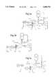
- FIGS. 1a-1cschematically illustrates a number of variations of a gas turbine plant wherein additional air is supplied to a combustor from an additional compressor.
- FIG. 2shows the supply of additional air from an additional compressor to a combustor in a gas turbine plant, in which the gas turbine and the compressor are divided into high-pressure and low-pressure units.
- BKdesignates a combustor in which a fuel is fired under high pressure.
- the high pressureis accomplished by means of a compressor C, which compresses air supplied to the combustor BK via an intercept and bypass valve V. Air to the compressor is admitted via the air conduit 8.
- the combustion gases which are generated in the combustor BKare passed via the intercept and bypass valve V to a gas turbine GT to utilize the energy in the combustion gases, whereupon the consumed waste gases are removed via a waste gas conduit 10.
- the gas turbine GTis mounted on the same shaft A as the compressor C and thus drives the compressor.
- a gear 12is arranged on the same shaft A on which the compressor C and the gas turbine GT are mounted.
- the gas turbine GTalso drives a generator G for conversion of energy utilized in the gas turbine plant to electrical energy.
- the intercept and bypass valve Vcomprises cut-off valves for compressor air to the combustor BK, cut-off valves for supply of combustion gases to the gas turbine GT, and also a bypass conduit with a cut-off valve to provide a possibility of short-circuiting the compressor C and the gas turbine GT.
- the inventionrelates to a method and a device for supplying the combustor BK with additional air by means of an additional compressor AC.
- Air to the additional compressor ACis sucked in via a second air intake 14 and is supplied to the combustor BK.
- the supply of the additional air to the combustor BKcan be arranged in several different ways.
- the additional aircan be passed via a conduit 16, as shown in FIGS. 1 and 2, to the intercept valve V in the same way as the air from the ordinary compressor C, whereupon the additional air is passed to the combustor BK.
- FIG. 1aalso shows an embodiment in which the additional air via a conduit 18 is injected into the ordinary compressor C at an injection hole 20 in the compressor C downstream of the air conduit 8, whereby the additional air is further compressed in the compressor C.
- the additional compressor ACis driven by the gas turbine GT via the gear 12.
- the additional compressor ACcan be driven by the gas turbine GT via the generator shaft, whereby the additional compressor AC is mounted via a clutch or a gear 22 to the generator shaft according to FIG. 1b.
- the additional compressor ACcan be driven via a separate electric motor M connected to the additional compressor AC, as shown in FIG. 1c.
- both the gas turbine GT and the compressor Care divided into several stages according to FIG. 2.
- the embodimentcorresponds to the more general connection according to FIGS. 1a-1c.
- the combustion gases from the combustor BKdrive a high-pressure turbine HPT, which is mounted together with a high-pressure compressor HPC on a first shaft A1.
- the gases expanded in the high-pressure turbine HPTare passed on to a low-pressure turbine LPT, from which the waste gases from the plant are removed via a waste gas conduit 10.
- the low-pressure turbine LPT and a low-pressure compressor LPCare mounted on shaft A2.
- airis passed via the air conduit 8, whereafter the air, after compression in the low-pressure compressor LPC, is passed to the high-pressure compressor HPC, where the air is compressed further before it is supplied to the combustor BK via the intercept valve V.
- the airmay be cooled in an intermediate cooler IC before being supplied to the high-pressure compressor HPC.
- the first shaft A1drives the generator G, via a gear 12, for generating electrical energy.
- airis compressed in an additional compressor AC and supplied to the combustor BK together with the air compressed in the high-pressure compressor HPC.
- Air to the additional compressor ACis taken in via the air intake 14 and passed to the intercept valve V to the same inlet of the valve V through which the compressed air from the high-pressure compressor HPC is fed in.
- the compressed airis passed from the additional compressor AC to the inlet of the high-pressure compressor HPC downstream of the intermediate cooler IC via the conduit alt1, or upstream of the intermediate cooler IC via the conduit alt2 in dependence on the type of high-pressure compressor and adaptation thereto and to optimize the performance.
- the generator Gin the preferred embodiment according to FIG.
- the additional compressoris arranged on an auxiliary shaft A3 connected to the gear 12, whereby the high-pressure turbine HPT drives the additional compressor AC via the gear 12.
- Direct operation of the additional compressor ACby mounting the additional compressor AC on the same shaft as the shaft of the high-pressure turbine HPT, that is on the first shaft A1, constitutes another operational alternative.
- the size of the additional compressoris small relative to the high-pressure compressor HPC normally existing in a gas turbine plant of the kind discussed.
- the air flow of the additional compressor ACis chosen to be 10% of the air flow of the high-pressure compressor HPC, a value which is however, in no way critical for the invention.
Landscapes
- Engineering & Computer Science (AREA)
- Chemical & Material Sciences (AREA)
- Combustion & Propulsion (AREA)
- Mechanical Engineering (AREA)
- General Engineering & Computer Science (AREA)
- Structures Of Non-Positive Displacement Pumps (AREA)
Abstract
Description
Claims (16)
Priority Applications (1)
| Application Number | Priority Date | Filing Date | Title |
|---|---|---|---|
| US08/744,322US5680752A (en) | 1992-08-28 | 1996-11-07 | Gas turbine plant with additional compressor |
Applications Claiming Priority (4)
| Application Number | Priority Date | Filing Date | Title |
|---|---|---|---|
| SE9202467ASE500150C2 (en) | 1992-08-28 | 1992-08-28 | Methods and apparatus for supplying additional air to a combustion chamber at a gas turbine plant |
| SE9202467 | 1992-08-28 | ||
| US38792895A | 1995-02-23 | 1995-02-23 | |
| US08/744,322US5680752A (en) | 1992-08-28 | 1996-11-07 | Gas turbine plant with additional compressor |
Related Parent Applications (1)
| Application Number | Title | Priority Date | Filing Date |
|---|---|---|---|
| US38792895AContinuation | 1992-08-28 | 1995-02-23 |
Publications (1)
| Publication Number | Publication Date |
|---|---|
| US5680752Atrue US5680752A (en) | 1997-10-28 |
Family
ID=26661509
Family Applications (1)
| Application Number | Title | Priority Date | Filing Date |
|---|---|---|---|
| US08/744,322Expired - LifetimeUS5680752A (en) | 1992-08-28 | 1996-11-07 | Gas turbine plant with additional compressor |
Country Status (1)
| Country | Link |
|---|---|
| US (1) | US5680752A (en) |
Cited By (18)
| Publication number | Priority date | Publication date | Assignee | Title |
|---|---|---|---|---|
| US6244037B1 (en) | 1998-07-07 | 2001-06-12 | Michael Nakhamkin | Method of operating a combustion turbine using supplemental compressed air |
| US6308512B1 (en)* | 1999-06-10 | 2001-10-30 | Enhanced Turbine Output Holding, Llc | Supercharging system for gas turbines |
| US6389793B1 (en) | 2000-04-19 | 2002-05-21 | General Electric Company | Combustion turbine cooling media supply system and related method |
| US6526758B2 (en) | 2000-05-12 | 2003-03-04 | General Electric Company | Method and apparatus for power augmentation for gas turbine power cycles |
| US6530224B1 (en) | 2001-03-28 | 2003-03-11 | General Electric Company | Gas turbine compressor inlet pressurization system and method for power augmentation |
| EP1510676A1 (en)* | 2003-08-13 | 2005-03-02 | Siemens Aktiengesellschaft | Gas turbine plant |
| US20070137216A1 (en)* | 2005-12-20 | 2007-06-21 | General Electric Company | Gas turbine engine assembly and method of assembling same |
| WO2010081883A3 (en)* | 2009-01-15 | 2011-01-27 | Sargas As | Improvements to fluidized bed combustion |
| US8607576B1 (en)* | 2012-06-07 | 2013-12-17 | United Technologies Corporation | Single turbine driving dual compressors |
| US20140030067A1 (en)* | 2012-07-25 | 2014-01-30 | Samsung Techwin Co, Ltd. | Gas turbine apparatus |
| US20140123620A1 (en)* | 2012-11-02 | 2014-05-08 | Exxonmobil Upstream Research Company | System and method for oxidant compression in a stoichiometric exhaust gas recirculation gas turbine system |
| US20140174474A1 (en)* | 2012-12-20 | 2014-06-26 | General Electric Company | Systems and methods for washing a gas turbine compressor |
| US20140319843A1 (en)* | 2013-02-26 | 2014-10-30 | Electric Jet, Llc | Micro gas turbine engine for powering a generator |
| US20160273762A1 (en)* | 2013-03-26 | 2016-09-22 | Tsukishima Kikai Co., Ltd. | Pressurized fluidized furnace equipment |
| US20170159565A1 (en)* | 2015-12-04 | 2017-06-08 | Jetoptera, Inc. | Micro-turbine gas generator and propulsive system |
| US20170234223A1 (en)* | 2016-02-11 | 2017-08-17 | Powerphase Llc | Gas turbine electrically driven supplementary air system for power augmentation and efficiency improvements |
| US20180058461A1 (en)* | 2015-03-19 | 2018-03-01 | Valeo Systemes De Controle Moteur | System for producing energy or torque |
| US20250270955A1 (en)* | 2021-11-03 | 2025-08-28 | Electric Power Research Institute, Inc. | Methods for Capacity Enhancement for a Gas Turbine Using Air Injection |
Citations (7)
| Publication number | Priority date | Publication date | Assignee | Title |
|---|---|---|---|---|
| US2365551A (en)* | 1941-03-01 | 1944-12-19 | Hermitte Louis Armand | Device for starting gas turbine motor plants |
| US2600235A (en)* | 1946-02-25 | 1952-06-10 | Galliot Jules Andre Norbert | Gas turbine rotor cooling means |
| US2626502A (en)* | 1947-05-29 | 1953-01-27 | Lagelbauer Ernest | Cooling system for gas turbine blading |
| US3585795A (en)* | 1967-12-30 | 1971-06-22 | Daimler Benz Ag | Gas turbine assembly having low-pressure groups and high-pressure groups adapted to be selectively connected either in series or in parallel |
| US4542621A (en)* | 1983-02-15 | 1985-09-24 | Ab Asea Atom | Method of and plant for combustion of water-vapor generating fuels |
| US4628687A (en)* | 1984-05-15 | 1986-12-16 | A/S Kongsberg Vapenfabrikk | Gas turbine combustor with pneumatically controlled flow distribution |
| US4974411A (en)* | 1986-12-22 | 1990-12-04 | Siemens Aktiengesellschaft | Supercharged coal-fired steam generator |
- 1996
- 1996-11-07USUS08/744,322patent/US5680752A/ennot_activeExpired - Lifetime
Patent Citations (7)
| Publication number | Priority date | Publication date | Assignee | Title |
|---|---|---|---|---|
| US2365551A (en)* | 1941-03-01 | 1944-12-19 | Hermitte Louis Armand | Device for starting gas turbine motor plants |
| US2600235A (en)* | 1946-02-25 | 1952-06-10 | Galliot Jules Andre Norbert | Gas turbine rotor cooling means |
| US2626502A (en)* | 1947-05-29 | 1953-01-27 | Lagelbauer Ernest | Cooling system for gas turbine blading |
| US3585795A (en)* | 1967-12-30 | 1971-06-22 | Daimler Benz Ag | Gas turbine assembly having low-pressure groups and high-pressure groups adapted to be selectively connected either in series or in parallel |
| US4542621A (en)* | 1983-02-15 | 1985-09-24 | Ab Asea Atom | Method of and plant for combustion of water-vapor generating fuels |
| US4628687A (en)* | 1984-05-15 | 1986-12-16 | A/S Kongsberg Vapenfabrikk | Gas turbine combustor with pneumatically controlled flow distribution |
| US4974411A (en)* | 1986-12-22 | 1990-12-04 | Siemens Aktiengesellschaft | Supercharged coal-fired steam generator |
Cited By (31)
| Publication number | Priority date | Publication date | Assignee | Title |
|---|---|---|---|---|
| US6305158B1 (en) | 1998-07-07 | 2001-10-23 | Michael Nakhamkin | Combustion turbine power plant operable at full power using supplemental compressed air |
| US6244037B1 (en) | 1998-07-07 | 2001-06-12 | Michael Nakhamkin | Method of operating a combustion turbine using supplemental compressed air |
| US6308512B1 (en)* | 1999-06-10 | 2001-10-30 | Enhanced Turbine Output Holding, Llc | Supercharging system for gas turbines |
| US6584779B2 (en) | 2000-04-19 | 2003-07-01 | General Electric Company | Combustion turbine cooling media supply method |
| US6389793B1 (en) | 2000-04-19 | 2002-05-21 | General Electric Company | Combustion turbine cooling media supply system and related method |
| US6481212B2 (en) | 2000-04-19 | 2002-11-19 | General Electric Company | Combustion turbine cooling media supply system and related method |
| US6526758B2 (en) | 2000-05-12 | 2003-03-04 | General Electric Company | Method and apparatus for power augmentation for gas turbine power cycles |
| US6530224B1 (en) | 2001-03-28 | 2003-03-11 | General Electric Company | Gas turbine compressor inlet pressurization system and method for power augmentation |
| EP1510676A1 (en)* | 2003-08-13 | 2005-03-02 | Siemens Aktiengesellschaft | Gas turbine plant |
| US20050086939A1 (en)* | 2003-08-13 | 2005-04-28 | Udo Schmid | Gas-turbine installation |
| US7024860B2 (en) | 2003-08-13 | 2006-04-11 | Siemens Aktiengesellschaft | Gas-turbine installation |
| US20070137216A1 (en)* | 2005-12-20 | 2007-06-21 | General Electric Company | Gas turbine engine assembly and method of assembling same |
| US8584464B2 (en)* | 2005-12-20 | 2013-11-19 | General Electric Company | Gas turbine engine assembly and method of assembling same |
| WO2010081883A3 (en)* | 2009-01-15 | 2011-01-27 | Sargas As | Improvements to fluidized bed combustion |
| US8607576B1 (en)* | 2012-06-07 | 2013-12-17 | United Technologies Corporation | Single turbine driving dual compressors |
| US20140030067A1 (en)* | 2012-07-25 | 2014-01-30 | Samsung Techwin Co, Ltd. | Gas turbine apparatus |
| US9435223B2 (en)* | 2012-07-25 | 2016-09-06 | Hanwha Techwin Co., Ltd. | Gas turbine apparatus |
| US9599070B2 (en)* | 2012-11-02 | 2017-03-21 | General Electric Company | System and method for oxidant compression in a stoichiometric exhaust gas recirculation gas turbine system |
| US20140123620A1 (en)* | 2012-11-02 | 2014-05-08 | Exxonmobil Upstream Research Company | System and method for oxidant compression in a stoichiometric exhaust gas recirculation gas turbine system |
| US10683801B2 (en) | 2012-11-02 | 2020-06-16 | General Electric Company | System and method for oxidant compression in a stoichiometric exhaust gas recirculation gas turbine system |
| US20140174474A1 (en)* | 2012-12-20 | 2014-06-26 | General Electric Company | Systems and methods for washing a gas turbine compressor |
| US9267437B2 (en)* | 2013-02-26 | 2016-02-23 | Electric Jet, Llc | Micro gas turbine engine for powering a generator |
| US20140319843A1 (en)* | 2013-02-26 | 2014-10-30 | Electric Jet, Llc | Micro gas turbine engine for powering a generator |
| US20160273762A1 (en)* | 2013-03-26 | 2016-09-22 | Tsukishima Kikai Co., Ltd. | Pressurized fluidized furnace equipment |
| US9933156B2 (en)* | 2013-03-26 | 2018-04-03 | Tsukishima Kikai Co., Ltd. | Pressurized fluidized furnace equipment |
| US20180058461A1 (en)* | 2015-03-19 | 2018-03-01 | Valeo Systemes De Controle Moteur | System for producing energy or torque |
| US20170159565A1 (en)* | 2015-12-04 | 2017-06-08 | Jetoptera, Inc. | Micro-turbine gas generator and propulsive system |
| US20240191875A1 (en)* | 2015-12-04 | 2024-06-13 | Jetoptera, Inc. | Micro-turbine gas generator and propulsive system |
| US20170234223A1 (en)* | 2016-02-11 | 2017-08-17 | Powerphase Llc | Gas turbine electrically driven supplementary air system for power augmentation and efficiency improvements |
| US11053851B2 (en)* | 2016-02-11 | 2021-07-06 | Powerphase International, Llc | Supplementary air injection system for gas turbines |
| US20250270955A1 (en)* | 2021-11-03 | 2025-08-28 | Electric Power Research Institute, Inc. | Methods for Capacity Enhancement for a Gas Turbine Using Air Injection |
Similar Documents
| Publication | Publication Date | Title |
|---|---|---|
| US5680752A (en) | Gas turbine plant with additional compressor | |
| US5459994A (en) | Gas turbine-air separation plant combination | |
| US5495709A (en) | Air reservoir turbine | |
| US10815882B2 (en) | Integrated power generation and compression train, and method | |
| US7383684B2 (en) | Hybrid engine | |
| US20120047906A1 (en) | Combustion turbine cooling media supply method | |
| US6269624B1 (en) | Method of operating a power plant with recycled CO2 | |
| US5491969A (en) | Power plant utilizing compressed air energy storage and saturation | |
| US6901759B2 (en) | Method for operating a partially closed, turbocharged gas turbine cycle, and gas turbine system for carrying out the method | |
| US4312179A (en) | Gas turbine power plant with air reservoir and method of operation | |
| US20060207260A1 (en) | Gas-turbine power generating installation and method of operating the same | |
| JPS60256522A (en) | Gas turbine engine apparatus and its operation | |
| US20040088987A1 (en) | Integrated gas compressor | |
| WO1994025746A1 (en) | High efficiency multi-shaft reheat turbine with intercooling and recuperation | |
| IL86379A (en) | Retrofit of simple cycle gas turbines compressed air energy storage | |
| US20060232071A1 (en) | Turbo set with starting device | |
| US5461861A (en) | Process for compressing a gaseous medium | |
| CA2543379C (en) | Turbo set with starting device | |
| CN101443558B (en) | Multi-stage compressor, air-separating apparatus comprising such a compressor, and installation | |
| JPH11210495A (en) | gas turbine | |
| EP0769098A1 (en) | Gas turbine plant with additional compressor | |
| US6726457B2 (en) | Compressor with supercharged inlet | |
| KR19990071577A (en) | Method and apparatus for supplying air to the combustor | |
| JPH08326554A (en) | Coal gasification gas turbine power generation equipment and its nitrogen supply method | |
| US5873709A (en) | Device for producing compressed air for various uses |
Legal Events
| Date | Code | Title | Description |
|---|---|---|---|
| STCF | Information on status: patent grant | Free format text:PATENTED CASE | |
| FPAY | Fee payment | Year of fee payment:4 | |
| FEPP | Fee payment procedure | Free format text:PAYOR NUMBER ASSIGNED (ORIGINAL EVENT CODE: ASPN); ENTITY STATUS OF PATENT OWNER: LARGE ENTITY | |
| FPAY | Fee payment | Year of fee payment:8 | |
| FPAY | Fee payment | Year of fee payment:12 | |
| AS | Assignment | Owner name:ABB CARBON AB, SWEDEN Free format text:ASSIGNMENT OF ASSIGNORS INTEREST;ASSIGNOR:SKOG, AGNAR;REEL/FRAME:028910/0638 Effective date:19950213 | |
| AS | Assignment | Owner name:ALSTOM POWER CARBON AB, SWEDEN Free format text:CHANGE OF NAME;ASSIGNOR:ABB CARBON AB;REEL/FRAME:030256/0802 Effective date:20000713 Owner name:ALSTOM TECHNOLOGY LTD, SWITZERLAND Free format text:ASSIGNMENT OF ASSIGNORS INTEREST;ASSIGNOR:ALSTOM POWER SWEDEN AB;REEL/FRAME:030256/0807 Effective date:20120802 Owner name:ALSTOM POWER SWEDEN AB, SWEDEN Free format text:MERGER;ASSIGNOR:ALSTOM POWER CARBON AB;REEL/FRAME:030257/0001 Effective date:20080220 |