US5680390A - Broadband telecommunications network and method of having operations systems support - Google Patents
Broadband telecommunications network and method of having operations systems supportDownload PDFInfo
- Publication number
- US5680390A US5680390AUS08/466,482US46648295AUS5680390AUS 5680390 AUS5680390 AUS 5680390AUS 46648295 AUS46648295 AUS 46648295AUS 5680390 AUS5680390 AUS 5680390A
- Authority
- US
- United States
- Prior art keywords
- network
- switch
- operations
- control system
- signals
- Prior art date
- Legal status (The legal status is an assumption and is not a legal conclusion. Google has not performed a legal analysis and makes no representation as to the accuracy of the status listed.)
- Expired - Lifetime
Links
- 238000000034methodMethods0.000titleclaimsdescription29
- 238000012545processingMethods0.000claimsabstractdescription27
- 238000012423maintenanceMethods0.000claimsabstractdescription21
- 230000005540biological transmissionEffects0.000claimsdescription10
- 230000008569processEffects0.000claimsdescription9
- 230000004913activationEffects0.000claimsdescription6
- 238000004806packaging method and processMethods0.000claimsdescription4
- 230000004044responseEffects0.000claimsdescription3
- 238000011144upstream manufacturingMethods0.000claims1
- 230000006870functionEffects0.000abstractdescription25
- 230000011664signalingEffects0.000description14
- 238000004891communicationMethods0.000description12
- 238000007726management methodMethods0.000description9
- 238000010586diagramMethods0.000description7
- 239000000835fiberSubstances0.000description6
- 238000013439planningMethods0.000description5
- 238000013519translationMethods0.000description5
- 238000004458analytical methodMethods0.000description4
- 230000009471actionEffects0.000description3
- 238000012544monitoring processMethods0.000description3
- 230000008520organizationEffects0.000description3
- 230000032258transportEffects0.000description3
- 238000013480data collectionMethods0.000description2
- 230000001934delayEffects0.000description2
- 238000013461designMethods0.000description2
- 238000005516engineering processMethods0.000description2
- 238000012986modificationMethods0.000description2
- 230000004048modificationEffects0.000description2
- 238000011017operating methodMethods0.000description2
- 238000012546transferMethods0.000description2
- 238000012550auditMethods0.000description1
- 230000008901benefitEffects0.000description1
- 230000015572biosynthetic processEffects0.000description1
- 230000000903blocking effectEffects0.000description1
- 230000008878couplingEffects0.000description1
- 238000010168coupling processMethods0.000description1
- 238000005859coupling reactionMethods0.000description1
- 125000004122cyclic groupChemical group0.000description1
- 238000007405data analysisMethods0.000description1
- 230000002950deficientEffects0.000description1
- 238000011161developmentMethods0.000description1
- 230000018109developmental processEffects0.000description1
- 238000011156evaluationMethods0.000description1
- 230000006872improvementEffects0.000description1
- 230000010354integrationEffects0.000description1
- 230000007774longtermEffects0.000description1
- 239000013307optical fiberSubstances0.000description1
- 230000002093peripheral effectEffects0.000description1
- 238000011084recoveryMethods0.000description1
- 238000003786synthesis reactionMethods0.000description1
- 230000033772system developmentEffects0.000description1
- 208000037820vascular cognitive impairmentDiseases0.000description1
Images


Classifications
- H—ELECTRICITY
- H04—ELECTRIC COMMUNICATION TECHNIQUE
- H04L—TRANSMISSION OF DIGITAL INFORMATION, e.g. TELEGRAPHIC COMMUNICATION
- H04L49/00—Packet switching elements
- H04L49/50—Overload detection or protection within a single switching element
- H—ELECTRICITY
- H04—ELECTRIC COMMUNICATION TECHNIQUE
- H04L—TRANSMISSION OF DIGITAL INFORMATION, e.g. TELEGRAPHIC COMMUNICATION
- H04L41/00—Arrangements for maintenance, administration or management of data switching networks, e.g. of packet switching networks
- H04L41/32—Specific management aspects for broadband networks
- H—ELECTRICITY
- H04—ELECTRIC COMMUNICATION TECHNIQUE
- H04L—TRANSMISSION OF DIGITAL INFORMATION, e.g. TELEGRAPHIC COMMUNICATION
- H04L49/00—Packet switching elements
- H04L49/25—Routing or path finding in a switch fabric
- H04L49/253—Routing or path finding in a switch fabric using establishment or release of connections between ports
- H04L49/255—Control mechanisms for ATM switching fabrics
- H—ELECTRICITY
- H04—ELECTRIC COMMUNICATION TECHNIQUE
- H04L—TRANSMISSION OF DIGITAL INFORMATION, e.g. TELEGRAPHIC COMMUNICATION
- H04L49/00—Packet switching elements
- H04L49/30—Peripheral units, e.g. input or output ports
- H04L49/3081—ATM peripheral units, e.g. policing, insertion or extraction
- H—ELECTRICITY
- H04—ELECTRIC COMMUNICATION TECHNIQUE
- H04L—TRANSMISSION OF DIGITAL INFORMATION, e.g. TELEGRAPHIC COMMUNICATION
- H04L49/00—Packet switching elements
- H04L49/55—Prevention, detection or correction of errors
- H—ELECTRICITY
- H04—ELECTRIC COMMUNICATION TECHNIQUE
- H04L—TRANSMISSION OF DIGITAL INFORMATION, e.g. TELEGRAPHIC COMMUNICATION
- H04L12/00—Data switching networks
- H04L12/54—Store-and-forward switching systems
- H04L12/56—Packet switching systems
- H04L12/5601—Transfer mode dependent, e.g. ATM
- H04L2012/5625—Operations, administration and maintenance [OAM]
- H—ELECTRICITY
- H04—ELECTRIC COMMUNICATION TECHNIQUE
- H04L—TRANSMISSION OF DIGITAL INFORMATION, e.g. TELEGRAPHIC COMMUNICATION
- H04L12/00—Data switching networks
- H04L12/54—Store-and-forward switching systems
- H04L12/56—Packet switching systems
- H04L12/5601—Transfer mode dependent, e.g. ATM
- H04L2012/5629—Admission control
- H04L2012/563—Signalling, e.g. protocols, reference model
- H—ELECTRICITY
- H04—ELECTRIC COMMUNICATION TECHNIQUE
- H04L—TRANSMISSION OF DIGITAL INFORMATION, e.g. TELEGRAPHIC COMMUNICATION
- H04L12/00—Data switching networks
- H04L12/54—Store-and-forward switching systems
- H04L12/56—Packet switching systems
- H04L12/5601—Transfer mode dependent, e.g. ATM
- H04L2012/5629—Admission control
- H04L2012/5631—Resource management and allocation
- H04L2012/5636—Monitoring or policing, e.g. compliance with allocated rate, corrective actions
- H—ELECTRICITY
- H04—ELECTRIC COMMUNICATION TECHNIQUE
- H04L—TRANSMISSION OF DIGITAL INFORMATION, e.g. TELEGRAPHIC COMMUNICATION
- H04L12/00—Data switching networks
- H04L12/54—Store-and-forward switching systems
- H04L12/56—Packet switching systems
- H04L12/5601—Transfer mode dependent, e.g. ATM
- H04L2012/5638—Services, e.g. multimedia, GOS, QOS
- H04L2012/5639—Tariffs or charging
Definitions
- the present inventionrelates to apparatus and operating methods for broadband intelligent networks, and more particularly to such networks in which effective and efficient operations are enabled through the integration of operations systems therewith.
- operationsmeans planning, engineering, provisioning, operating, and maintaining the network, billing customers for services, and receiving and processing customer requests for information, service, and maintenance.
- Network operationsare assisted by operations systems, each of which typically includes a computer-based system, programmed to execute particular operations functions on the basis of data received from various elements of the network.
- the existing circuit-switched network in the United Stateshas numerous exchange switches, each of which is interfaced to multiple operations systems that provide predetermined, basic operations system functions.
- the basic operations system functional componentsinclude Operations (O), Administration (A), Maintenance (M), Provisioning (P) and Billing (B).
- each operations systemis designed to support multiple exchange switches, and each switch is typically linked to perhaps four or five operations systems that provide different operations system functions. Larger exchange switches are typically interfaced with a greater number of operations systems.
- an exchange switchmay be interfaced with a traffic data collection operations system for administrative purposes.
- the exchange switchmay further be interfaced with a surveillance system for maintenance purposes, a memory administration system for operations purposes, and a billing operations system.
- Each data communication link from an exchange switch to an operations systemnormally is a dedicated link which has an electronic controller at each end and which may be as long as twenty or more miles. Operations system interfaces in the prior art are thus very costly.
- Remote switching systemshave been employed in the circuit-switched network to enable operations system functions to be provided to smaller and/or more remotely located exchange switches. For example, up to ten or more remote switches may be coupled through data links to a host exchange switch which in turn is interfaced to a family of operations systems to obtain support for the host switch and the remote switches.
- the remote switching concepthas made it economically feasible to provide operations system support in rural areas where very small exchange switches are required.
- a new type of telecommunications networkknown as a fast-packet network, allows all-digital, broadband, multimedia communication between calling and called parties.
- These fast-packet networkshave generally operated without real-time network control and with little or no operations system support.
- the existing CSN operations systemsare not particularly suited for use in fast-packet networks, at least without modification.
- a broadband intelligent networkhas been developed as an improved network over previous fast-packet networks.
- a Service Control PointSCP
- ISCPIntegrated Service Control Point
- the SCPreceives a signaling cell from a CPE unit requesting that a Switched Virtual Circuit (SVC) be established to a called party.
- SVCSwitched Virtual Circuit
- the SCPresponds by sending a command cell with translation data to Connection Management software in an asynchronous transfer mode (ATM) switch or other fast-packet switch, and by subsequently alerting the called party through the use of a signaling cell.
- ATMasynchronous transfer mode
- the BINprovides intelligent network control of call handling and other network services as is disclosed in greater detail in the following applications, both of which are assigned to the present assignee and are hereby incorporated by reference: Ser. No. 08/063,661, entitled “Intelligent Broadband Communication System and Method,” filed by Richard B. Robrock on May 20, 1993 (now abandoned) and Ser. No. 08/069,243, entitled “Intelligent Broadband Communication System and Method,” filed as a Continuation-in-Part application of Ser. No. 08/063,661 by Richard B. Robrock on May 28, 1993and now U.S. Pat. No. 5,539,884, issued Jul. 23, 1996.
- the BINgenerally operates with improved functionality for fast-packet networks. It is desirable that the BIN be developed structurally so that operations systems support is provided in fast-packet networks with improved economy, efficiency, and functionality.
- the present inventionis directed to a BIN and a BIN operating method in which operations systems support is provided with improved functionality, better economy, and better efficiency.
- a broadband intelligent networkcomprises a fast-packet switch having a plurality of ports and a switch processor for establishing switched virtual port connections, for routing cells through the connections to and from the ports, and for processing network operations signals.
- a network control systemis coupled to the switch processor to receive network operations signals therefrom and to send network operations signals thereto, and a family of operations systems is interfaced with the network control system.
- the network control systemhas routing means for sending operations signals between the switch processor and the operations systems.
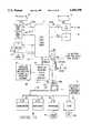
- FIGS. 1A and 1Bshow respective network diagrams for first and second embodiments in which operations systems are integrated in a broadband intelligent network in accordance with the invention to provide improved network operation;
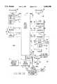
- FIGS. 2A and 2Bshow respective network diagrams for third and fourth embodiments in which operations systems are integrated in a broadband advanced intelligent network in accordance with the invention to provide improved network operations:
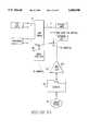
- FIG. 3is a system functional diagram which illustrates the operation of the network of FIG. 1A, 1B, 2A, or 2B;
- FIGS. 4A and 4Billustrate in greater detail an Administration Operations System employed in the networks of FIGS. 1A-2B;
- FIGS. 5A and 5Billustrate in greater detail a Maintenance Operations System employed in the networks of FIGS. 1A-2B;
- FIGS. 6A and 6Bshow in greater detail a Provisioning Operations System employed in the networks of FIGS. 1A-2B.
- the present inventionis directed to a broadband intelligent network (BIN) in which a family of operations systems perform the operations functions needed for reliable, effective, efficient, and economic BIN operation.
- the operations systemssupport such functions as provisioning, traffic data collection, billing, and surveillance.
- Each operations systemis structured to provide predetermined operations functions and is interfaced with the BIN through a network controller or through one or more fast-packet switch ports. In the interface, communication paths are established to and from the operations systems preferably to allow a single family of operations systems to support the entire BIN.
- a BIN 50 of the inventionis structured and operated on the basis of fast-packet technology.
- a fast-packet networkmeans a network that transports digital data in packets at high transport rates (typically megabits per second) with sub-millisecond switch delays and without retransmission of errored packets.
- the BIN 50includes a fast-packet switch 51 preferably in the form of an ATM switch.
- the fast-packet switch 51has a plurality of two-way ports 60 and 62, each of which may be provided with fiber optic links to subscribers.
- a fiber optic link or connection hereinmeans a connection established wholly or partly using fiber optic facilities. Each fiber optic link can provide connections for multiple subscribers. Other media such as coaxial cable or wire pairs may be employed at lower speeds where appropriate.
- the BIN 50further includes a network control system called a BIN Service Control Point (BIN-SCP) 61, and a backup BIN-SCP 61B.
- the ATM switch 51has a switch processor 64 with connection management software 30 and other software.
- the BIN-SCP 61has service request or call processing software 31 and is generally structured as described in my U.S. Pat. No. 5,539,884, issued Jul. 23, 1996.
- Each customerhas a CPE unit that is connected directly or indirectly to an ATM fast-packet switch port.
- a calling party CPE 52 (CPE1) and a called party CPE 54 (CPE2)are representatively shown with respective ATM switch port connections from terminals 52C and 54C to ports 52P and 54P.
- a system 63 of resource units R1 through Rn(an example of a resource unit includes a Line Information Data Base ("LIDB")) is interfaced to respective ports 62 of the ATM switch 51 either by direct connection as indicated by connection paths 70-1 through 70-n, by indirect connection through other ATM switches (not shown), or by other indirect connection through multiplexer circuitry (not shown) or other interface circuitry (not shown).
- LIDBLine Information Data Base
- the term "interfaced" as used herein regarding connection of a resource unit, a server unit, or an operations system to a fast-packet or ATM switch portmeans a "direct” connection to the port or an "indirect” connection to the port through one or more fast-packet or ATM switches and/or through multiplexer or other interface circuitry.
- the BIN 50further includes a server system 57 having a plurality of servers S1 through Sn.
- Each serveris generally structured with service circuitry to provide a special service on request by calling parties.
- the servers S1 through Snmay include servers that exist in the circuit-switched network and are interfaced for operation with the BIN 50, as well as servers structured for operation only in the BIN 50.
- the server S1is an Intelligent Services Peripheral ("ISP") having service circuits which provide certain basic services such as speech synthesis, voice recognition, and voice recording and playback when requested by a calling or called party.
- the ISP S1may be a server dedicated to the BIN 50 or a server that exists in the CSN and is adapted to be operational in the BIN 50.
- the BIN 50includes a plurality of operations systems (OSs) 80 which are interfaced with the BIN-SCPs 61 and 61B (the broadband network control system or network controller) to provide operations support for the BIN 50 with improved functionality and better economy and efficiency.
- An interfaced OS 80means an OS coupled through an ATM port as previously defined, and, in addition, an OS directly or indirectly coupled to a network controller for the broadband network.
- OSsmay be organized in a variety of ways to provide network support needed for broadband network operations.
- each OShas been categorized according to the basic management objectives that it serves.
- each OS in the CSNhas usually been categorized as a system that operates to provide Administration (A), Maintenance (M), Provisioning (P) or Billing (B) objectives.
- AAdministration
- MMaintenance
- PProvisioning
- BBilling
- a family of basic OSs and the organization of OS functionsmay generally be embodied in various ways as previously indicated.
- the conventional OS organization of A, M, P and B OSsis employed as an architecture for the family of basic OSs.
- Each basic A, M, P or B OSmay in turn be partitioned into a subfamily of OSs directed to its basic function or management objective. OSs that are included in a subfamily may be further partitioned by function, geographic area or by both function and geographic area.
- the basic OSs 80are illustrated in FIG. 1A as including the four basic OSs, 86, 88, 90 and 92, which respectively provide the conventional operations basic functions i.e., administration, maintenance, provisioning, and billing functions as OS support for the BIN 50.
- Billingis implemented through the use of a billing operations system 92 located, for example, at a regional accounting office (RAO) 92A.
- RAOregional accounting office
- Billing data acquired by the network controlleris transmitted to the RAO for processing as more fully disclosed in my aforementioned U.S. Pat. Nos. 5,539,884 and 5,392,402, and my patent application Ser. No. 08/125,978.
- any OSmay be an entirely new OS, having its design driven by considerations of the design and needs of a BIN, or any OS may essentially be a CSN OS which is adapted for interfacing with a BIN.
- all of the OSsare data-linked to the network through the network controller and the connection 53 or 55 which functions as an umbilical coupling for the OSs.
- the network controllerthus operates principally as a data handler in the operation of the network OSs. Further, maximum use can thus be made of previously installed equipment in a telecommunications infrastructure.
- the OSs 80 and the BIN-SCPs 61 and 61Bare appropriately interfaced to provide communication paths for two-way data flow between the BIN 50 and the OSs 80 in accordance with the invention.
- a BIN 50Ais shown as another embodiment of the invention in FIG. 1B. Like reference characters are employed for like elements in the embodiments of FIGS. 1A and 1B.
- Each OSis normally a computer-based system which automates some aspect(s) of network or service management.
- a wide variety of BIN support functionscan thus be provided by OSs, as further considered subsequently herein.
- the basic OSs 80are interfaced to the fast-packet switch 51 through two-way connections from system terminals 86C through 92C to switch ports 86P through 92P.
- the number of port connectionscorresponds to the number of different basic OSs 80, i.e., four OSs 86-92.
- each partitioned OSmay be provided with its own port (not indicated in drawing).
- fewer portscan be employed through use of port sharing (not indicated) by the basic and/or partitioned OSs.
- the interface connections 86C-92C for the OSs 86-92may be direct to the ATM switch 51 or indirectly to the ATM switch 51 through one or more other fast-packet switches (not specifically shown) and/or through other interface circuitry (not shown) such as multiplexer circuitry which may be used for port sharing.
- BIN-ISCPBIN Integrated Service Control Point
- FIGS. 2A and 2Ba BIN Integrated Service Control Point 285 or 285B is interfaced directly with the ATM switch 51 in a broadband advanced intelligent network 280 and provides network control with improved operations support similar to that described for the BIN-SCP 61 or 61B.
- BIN-ISCPBIN Integrated Service Control Point
- FIGS. 2A and 2BLike reference characters are employed in FIGS. 2A and 2B for elements like those in FIG. 1A and 1B.
- the BIN 280 of FIG. 2Adiffers in operations systems support from the BIN 50 of FIG. 1A, principally through the provision of an OS 94 that provides a service creation function for the network.
- the OS 94is a subfamily member of the P OSs 90 as shown.
- a SPACE® system and appropriate network controller structuringi.e., ISCP
- ISCPnetwork controller structuring
- a BIN 280Ais shown as an additional embodiment of the invention.
- the BIN 280Ais like the BIN 280 of FIG. 2A, but the BIN 280A has basic OSs 80 interfaced to ports of the fast-packet switch 51 as in the case of the BIN 50A of FIG. 1A.
- Service OSsincluding the SPACE® system, may be directly coupled to the ISCP 285 or 285B.
- command cellsare generated by the network controller (BIN-SCP 61 or 61B or BIN-ISCP 285 or 285B) and transmitted through the umbilical connection 53 and the switch port 49 or 49B, thereby populating a translation or lookup table in the switch processor 64.
- Switched virtual connectionsare thus established and terminated for voice, data, image, and video communication cells, as described more fully hereinafter in connection with FIG. 3.
- Command datamay alternatively be transmitted to the processor 64 through a data link 55.
- the network controllermay send signaling, command, and query cells to CPE units and resource and server units for communication and control purposes.
- the switch 51is a fast-packet (FP) switch which can be embodied in various forms, with some variation in the manner in which transmitted data is organized.
- FPfast-packet
- current state-of-the-art FP switchesinclude the preferred ATM switches (data organized in fixed-length packets called "cells"), SMDS switches, and frame relay switches.
- cellmeans a basic data packaging unit regardless of whether the unit is called a "cell", a "packet", or other name in the particular technology used to apply the invention.
- the preferred ATM switchis a connection-oriented switch, which may have up to 1000 or more ports, employ virtual connections, and operate with fixed length data packets (cells).
- ATM switchescan handle signals with transport rates of 155 Mb/s or greater and they introduce only sub-millisecond delays in transit time and in delay variability. The maximum expected delay through an ATM switch with 155 Mb/s ports is 150 microseconds.
- the asynchronous transfer mode used in ATM switchesis a CCITT standard for packaging, multiplexing, and switching end user digital information in fixed length data packets (cells), 53 bytes (octets) in length.
- the data cellindicated at 67C and 69 in FIGS. 1A, 1B, 2A, and 2B, includes a header, to which 5 bytes are assigned, and a payload portion, to which 48 bytes are assigned.
- the cell headernormally contains both a Virtual Path Indicator (VPI) and a Virtual Channel Indicator (VCI).
- VPIs and VCIsare used to determine the routing of cells through permanent or switched virtual connections. These connections are termed virtual because they exist in the physical sense only for as long as a cell traverses the ATM switch.
- the self-routing ATM switchuses the port identity and the VPI/VCI of incoming cells to establish the proper output port to which each cell should be routed based on lookup tables.
- the lookup (or translation) tablestie a cell with a particular label from a particular input port to a specified output port and give the cell a different label.
- Signaling cellsare preferably used to establish switched virtual connections through the ATM switch 51.
- a "signaling cell"a response cell, a command cell, a data cell, or other ATM cell may be a single cell or a sequence of cells.
- a signaling cellhas the same format as the ATM cells described above.
- Signaling cells generated by a calling CPErequest a particular service and contain the information in their payload necessary to provide the requested service, such as to complete a connection to another CPE, i.e., calling party address, called party address, billing information, digital bandwidth required, personal identification number (PIN), Calling Card number, etc.
- Signaling cellscan be identified by unique values of the VPI and VCI or by a unique payload type code. If desired, the recently developed Q.93B signaling protocol may be used with the BIN 50, 50A, 280, or 280A.
- the BIN-SCP 61 or BIN-ISCP 285is connected to a port 49 of the ATM switch 51 for network communications, preferably through the umbilical connection 53 which may be a direct fiber optic link.
- the umbilical data link 55can be employed as an alternate communication link to the switch processor 64. If the ATM switch 51 is handling OC-3 at 155 Mb/s, as shown, the interface with the BIN-SCP or BIN-ISCP is preferably at the same 155 Mb/s rate.
- a backup BIN-SCP 61B or BIN-ISCP 285Bis connected to ATM switch port 49B through direct connection 53B to provide network-controlled services with extremely high reliability. If the BIN SCP 61 or BIN-ISCP 285 fails, the BIN SCP 61B or BIN-ISCP 285B immediately takes control of network services.
- the BIN-SCP 61 or 61B or the BIN-ISCP 285 or 285Bcan share ports 49 and 49B, respectively, with other devices. As such, multiplexing equipment, etc., may be present in the connection between the BIN-SCP or BIN-ISCP and the switch port.
- the BIN-SCP 61 or 61B or the BIN ISCP 285 or 285Bmay also be interfaced (not shown) with a CSN to provide network controlled services therein as more fully set forth in the aforementioned U.S. Pat. No. 5,539,884.
- the primary and backup BIN-SCPs or BIN-ISCPsare also preferably directly connected to ports of other ATM switches (not shown).
- routing to (or from) other ATM switchescan be through the ATM switch port 49 or 49B and through a permanent virtual connection in the ATM switch 51 to the destination ATM switch (not shown). Permanent virtual circuits would also be established in the destination and any intermediate ATM switches.
- FIG. 3The operation of the BIN of each embodiment of the invention in FIGS. 1A-2B, in establishing a call connection, is illustrated by the functional block diagram in FIG. 3.
- the calling party CPE 52(FIG. 1) generates a signaling cell to request a connection to a called party 54 or a network device, e.g., a resource unit, at a defined address (directory number) with a defined bandwidth corresponding, for example, to voice, data, image, or video.
- a network devicee.g., a resource unit
- the ATM switch 51routes the signaling cell through a permanent virtual circuit to the BIN-SCP or BIN-ISCP which, in block 94, responds to the cell information and processes the request for a call connection and thereafter generates a command cell for the ATM switch 51 to establish the connection. In addition, a signaling cell is generated for the called party.
- the ATM command cell and the called party signaling cellare sent directly to the ATM switch 51 through port 49 (FIG. 1A) as indicated by block 96.
- the connection management processor of the ATM switch 51acts on information in the command cell and populates its translation table in accordance with the received command, thereby establishing a two-way switched virtual connection between ATM ports 52P and 54P of the calling and called parties.
- the signaling cell generated by the BIN-SCP or BIN-ISCPis immediately routed through the ATM port 54P to the called party as indicated by reference character 97 (FIG. 3).
- the ATM switch 51routes calling and called party cells 67C and 69 (FIG. 1) through a two-way, switched virtual path.
- the translation tabledefines the two-way path so that each party receives the voice, data, image, and/or video cells transmitted by the other party.
- system elements of the BINcan be operated during the call to process mid-call bandwidth changes or other requests or to process a call termination request.
- the CPE units 52 and 54, the resource unit 63, the server unit 57, the ATM switch 51, and the BIN-SCP 61are operated to establish call changes or a call termination in a manner similar to that described for the original connection service.
- BIN operations to establish call connections, make mid-call changes, and terminate callsare more fully explained in the incorporated U.S. Pat. No. 5,539,884.
- the basic OSs 84-90include operations systems structured and operated as follows.
- An illustrative Administration OS 86collects and processes traffic data needed for switch congestion control, i.e., overload management, and for network engineering and planning purposes in the embodiment of FIG. 1A.
- various kinds of traffic dataare gathered by the ATM switch 51 under the control of software 86-1.
- peg counters (86-2)may be used to count cells per second at switch ports, and the cells/second and any other traffic data are then reported by traffic reporting cells through the umbilical connection 53 to the network controller or BIN ISCP 285 under control of the switch processor 64.
- traffic datamay be communicated directly from the switch processor 64 to the network controller 285 through the OS umbilical data links 55.
- the network controller 285routes traffic data obtained from the traffic data cells to the OS 86 for collection and analysis.
- the overloadis quickly detected by network overload management software 86-3 so that quick responsive actions can be taken to reduce the load. In this way, quality telecommunications service can be maintained for customers already using the network.
- the OS 86determines the offered load on the switch 51 from moment to moment, and, if an overload occurs, further determines network control actions which will avoid switch overload and provides switch and network congestion control. Switch overload may be avoided by control actions taken with respect to the switch 51 alone or together with other network switches and/or elements.
- the BIN ISCPgenerally acts as a data handler for OS related data, exceptions may exist.
- the BIN ISCPmay be structured to respond immediately to an overload alarm and invoke congestion control, such as throttling back cells by periodically blocking new cells.
- the Administration OS 86further employs software 86-4 which analyzes traffic data for network engineering and planning purposes. This analysis preferably includes a long-term evaluation of traffic data as a function of time to determine loading trends which management can use in making engineering and network planning decisions.
- the OS 86determines the work effort of the ATM switch 51 as a function of time, and resulting data indicates when switch growth is needed to handle increasing levels of traffic.
- a computer system(not specifically indicated) is preferably included in the Administration OS 86 to perform required operation functions on input data received from the network.
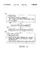
- FIG. 4BA functional processing diagram in FIG. 4B illustrates the manner in which various elements of the BIN operate in conjunction with the Administration OS 86 to provide traffic data analysis and control and to produce traffic data reports.
- the Administration OS 86to provide traffic data analysis and control and to produce traffic data reports.
- functionsare performed by computers within the BIN, programmed procedures are executed by such computers to provide such functions.
- peg counters in the fast-packet switch 51are read by the switch processor 64 at specified intervals to determine the volume of cell traffic at each peg (i.e., the number of cells handled during the specified interval of time). At the end of each time interval, the port counters are reset by the switch processor 64.
- the port traffic datais packaged in cells for transmission to the OS 86.
- the switch processor 64then transmits, step 86A3, the traffic data cells through the ATM switch 51 to a data and reports system (DRS) in the OS 86.
- DRSdata and reports system
- the data link 55may be used for transmitting packaged traffic data through the network controller to the OS 86.
- step 86A4interval reports are developed in which actual traffic data are compared with specified thresholds, and when a threshold is exceeded, a command is sent to the switch processor to manage the port traffic so that the offered load is throttled back to the threshold level.
- the OS86compares actual traffic data with stored historical traffic data for generation of a trend report which may be used by management for future network planning.
- An illustrative Maintenance OS 88is a surveillance system, as shown, for example, in FIG. 5A, which processes alarm data received from various monitored network elements (such as fiber optic transmission systems, ATM switch elements, network controller, etc.).
- monitored network elementssuch as fiber optic transmission systems, ATM switch elements, network controller, etc.
- each monitored network element or systemis provided with a self-alarm capability and some level of self recovery, and in many cases, with a redundant backup element or system.
- a minor alarmis issued when a problem has occurred without affecting service.
- a major alarmis issued when a failure has occurred and service has been or will be affected.
- the ATM switch 51accordingly employs an incoming transmission facilities monitor 89I and an equipment monitor 89E which generate minor or major alarm data when a failure condition is detected.
- the incoming facilities monitor 89Ican, for example, be a small processor which checks ATM cell headers for CRC errors and generates an alarm signal which is coupled to the switch processor to indicate an incoming facility failure such as a defective optical fiber connection.
- the switch processor 64controls transmission of the failure alarm data using monitor reporting communication cells from the ATM switch 51 through the umbilical connection 53 to the network controller 285 which sends the data to the M-OS 88 for recording, processing, and analysis.
- a network controller monitorgenerates an alarm signal for the OS 86 when the network controller 285 fails and is automatically replaced by the backup controller 285B (FIG. 2A or 2B).
- FIG. 5BA functional processing diagram in FIG. 5B illustrates the manner in which various elements of the BIN operate with the Maintenance OS 88 to provide alarm data monitoring and congestion control.
- the incoming facilities monitor 89I or the equipment monitor 89Edetects an alarm condition.
- Each monitor 89I or 89Emight include a microprocessor (not shown) which is programmed to detect and transmit specific alarm conditions from input signals received from facilities or equipment.
- step 88A2the switch processor 64 receives alarm signals from the monitors and, in turn, generates a message for each alarm. As indicated by step 88A3, the switch processor 64 packages alarm messages in data reporting cells which are transmitted through the umbilical 53 to the network controller 285. In turn, the network controller 285 forwards the alarm messages to the maintenance OS 88.
- the Maintenance OS 88responds to the alarm message with the execution of a programmed procedure to determine which, if any, diagnostic routine should be run on the alarmed facility or equipment. A request is then made through the network controller and the umbilical connection 53 for the switch processor 64 to run the determined diagnostic routine. Alternatively, the request may be directly data linked through the umbilical 55 to the switch processor 64.
- step 88A5the switch processor 64 operates under the control of the software 63M2 and runs the requested diagnostic routine relative to the alarmed facility or equipment. In this process, additional data may be obtained from the alarmed facility or equipment.
- the switch processor 64packages the results of the diagnostic in data reporting cells which are transmitted through the umbilical 53 to the network controller 285. The network controller 285 forwards the results to the Maintenance OS 88.
- Provisioning systemsare used to put in place whatever physical resources are needed in the network to provide a customer with a particular service.
- the networkhas basic resources required to provide services needed by a customer equipped to interface with the network.
- a Provisioning OS 90assigns the network resources needed by the customer and populates network data bases with information about that customer, the customer's station equipment, and the customer's services.
- the P-OS 90includes a SPACE® system 94 that creates customer services as described in the incorporated group of patent applications related to the SPACE® system, and as further described in the other incorporated patent applications.
- the SPACE® systemis directly linked to the network controller 285.
- Dotted line 90Dindicates that the SPACE® system is a part of the P-OS 90.
- Other parts of the P-OS 90are linked to the network through the ATM switch 51.
- service provisioningbegins at step 90A1 by creating a customer record in a service management system in the Provisioning OS 90.
- the customer recorddefines the customer service and includes a pending activation time for the service.
- step 90A3the network controller sends a command cell to the ATM switch 51 where the command is acted upon by the connection management software in the switch processor.
- a permanent virtual channelis thus established between the customer's CPE and the network controller so that the service can be invoked.
- a billing OS 92is used to process customer billing data received from the network controller for use of network resources and other services.
- the billing data for connection service(for voice, data, image/video transmission) is based, for example, on identification of the numbers of the calling and called parties, the bandwidth used, and the time the call or session is placed, answered and terminated.
- the network controllerpreferably collects and assembles the billing data and sends it to the billing OS 92 at the completion of each call or session, or it can send data as it is collected. If the latter method is used, the billing OS-92 includes a capability to correlate the incoming billing records.
Landscapes
- Engineering & Computer Science (AREA)
- Computer Networks & Wireless Communication (AREA)
- Signal Processing (AREA)
- Data Exchanges In Wide-Area Networks (AREA)
Abstract
Description
Claims (19)
Priority Applications (1)
| Application Number | Priority Date | Filing Date | Title |
|---|---|---|---|
| US08/466,482US5680390A (en) | 1995-06-06 | 1995-06-06 | Broadband telecommunications network and method of having operations systems support |
Applications Claiming Priority (1)
| Application Number | Priority Date | Filing Date | Title |
|---|---|---|---|
| US08/466,482US5680390A (en) | 1995-06-06 | 1995-06-06 | Broadband telecommunications network and method of having operations systems support |
Publications (1)
| Publication Number | Publication Date |
|---|---|
| US5680390Atrue US5680390A (en) | 1997-10-21 |
Family
ID=23851922
Family Applications (1)
| Application Number | Title | Priority Date | Filing Date |
|---|---|---|---|
| US08/466,482Expired - LifetimeUS5680390A (en) | 1995-06-06 | 1995-06-06 | Broadband telecommunications network and method of having operations systems support |
Country Status (1)
| Country | Link |
|---|---|
| US (1) | US5680390A (en) |
Cited By (68)
| Publication number | Priority date | Publication date | Assignee | Title |
|---|---|---|---|---|
| US5825780A (en) | 1994-05-05 | 1998-10-20 | Sprint Communications Co.L.P. | Method, system and apparatus for telecommunications control |
| US5835566A (en)* | 1996-03-29 | 1998-11-10 | Telecom Technologies, Inc. | System and method for providing in-band and out-of-band testing of telecommunications network components |
| US5887127A (en)* | 1995-11-20 | 1999-03-23 | Nec Corporation | Self-healing network initiating fault restoration activities from nodes at successively delayed instants |
| US5920562A (en) | 1996-11-22 | 1999-07-06 | Sprint Communications Co. L.P. | Systems and methods for providing enhanced services for telecommunication call |
| US5940393A (en) | 1996-05-28 | 1999-08-17 | Sprint Communications Co. L.P. | Telecommunications system with a connection processing system |
| US5991301A (en) | 1994-05-05 | 1999-11-23 | Sprint Communications Co. L.P. | Broadband telecommunications system |
| US6002689A (en) | 1996-11-22 | 1999-12-14 | Sprint Communications Co. L.P. | System and method for interfacing a local communication device |
| US6014378A (en) | 1996-11-22 | 2000-01-11 | Sprint Communications Company, L.P. | Telecommunications tandem system for circuit-based traffic |
| US6023474A (en) | 1996-11-22 | 2000-02-08 | Sprint Communications C.O.L.P. | Broadband telecommunications system interface |
| US6026091A (en) | 1996-02-02 | 2000-02-15 | Sprint Communications Co. L.P. | ATM gateway system |
| US6031840A (en) | 1995-12-07 | 2000-02-29 | Sprint Communications Co. L.P. | Telecommunications system |
| US6067299A (en) | 1997-04-16 | 2000-05-23 | Sprint Communications Company, L.P. | Communications system for providing ATM connections and echo cancellation |
| US6081525A (en) | 1995-09-08 | 2000-06-27 | Sprint Communications Co., L.P. | Broadband telecommunications system |
| US6081529A (en)* | 1995-11-22 | 2000-06-27 | Sprint Communications Company, L. P. | ATM transport system |
| US6081589A (en)* | 1997-12-01 | 2000-06-27 | Nortel Networks Corporation | Method and apparatus for identifying and handling on-line access calls within a switch |
| WO2000049775A1 (en)* | 1999-02-16 | 2000-08-24 | Telefonaktiebolaget Lm Ericsson (Publ) | Establishing internal control paths in an atm node |
| US6115380A (en) | 1996-11-22 | 2000-09-05 | Sprint Communications Co., L.P. | Broadband telecommunications system |
| US6118936A (en)* | 1996-04-18 | 2000-09-12 | Mci Communications Corporation | Signaling network management system for converting network events into standard form and then correlating the standard form events with topology and maintenance information |
| US6137800A (en) | 1997-05-09 | 2000-10-24 | Sprint Communications Company, L. P. | System and method for connecting a call |
| WO2000072572A1 (en)* | 1999-05-20 | 2000-11-30 | Motorola Inc. | Session based billing in a communication system |
| US6172977B1 (en) | 1994-05-05 | 2001-01-09 | Sprint Communications Company, L. P. | ATM direct access line system |
| US6178170B1 (en) | 1997-05-13 | 2001-01-23 | Sprint Communications Company, L. P. | System and method for transporting a call |
| FR2797964A1 (en)* | 1999-08-23 | 2001-03-02 | Thomson Csf Sextant | SECURE DATA SWITCHING CONTROL DEVICE |
| US6249529B1 (en) | 1995-09-08 | 2001-06-19 | Sprint Communications Company, L.P. | Telecommunications apparatus, system, and method with an enhanced signal transfer point |
| US20010004768A1 (en)* | 1998-09-28 | 2001-06-21 | Hodge Winston W. Hodge Winston W. | Highly integrated computer controlled digital head end |
| US20010005908A1 (en)* | 1998-09-28 | 2001-06-28 | Hodge Winston W. | Method for buffering video, data and voice signals using a common shared bus |
| US6262992B1 (en) | 1996-11-22 | 2001-07-17 | Sprint Communications Company, L. P. | System and method for transporting a call in a telecommunication network |
| US6314103B1 (en) | 1994-05-05 | 2001-11-06 | Sprint Communications Company, L.P. | System and method for allocating bandwidth for a call |
| US20020004788A1 (en)* | 2000-05-19 | 2002-01-10 | Gros Thomas D. | Commodity trading of bandwidth |
| US20020012352A1 (en)* | 1998-12-18 | 2002-01-31 | Goran Hansson | Internet protocol handler for telecommunications platform with processor cluster |
| GB2365255A (en)* | 2000-07-25 | 2002-02-13 | Marconi Comm Ltd | Partitioned switch |
| US6351521B1 (en) | 1998-04-10 | 2002-02-26 | Sprint Communications Company L.P. | Communications test system |
| US20020024955A1 (en)* | 2000-08-29 | 2002-02-28 | Nec Corporation | Asynchronous transfer mode switching system |
| US20020056125A1 (en)* | 1998-09-28 | 2002-05-09 | Hodge Winston W. | Multi-tier buffering system and method which combines video, data, and voice packets |
| US20020056143A1 (en)* | 1998-09-28 | 2002-05-09 | Hodge Winston W. | Programmable broadband downstream module |
| US6389131B1 (en)* | 1998-09-28 | 2002-05-14 | Lucent Technologies Inc. | Enhanced initiate call attempt |
| US20020065917A1 (en)* | 2000-11-30 | 2002-05-30 | Pratt Steven L. | Method for managing resources on a per user basis for UNIX based systems |
| US20020082014A1 (en)* | 2000-12-22 | 2002-06-27 | Staffan Andersson | Connection handling in SRNC relocation |
| US6430195B1 (en) | 1994-05-05 | 2002-08-06 | Sprint Communications Company L.P. | Broadband telecommunications system interface |
| US6470019B1 (en) | 1998-02-20 | 2002-10-22 | Sprint Communications Company L.P. | System and method for treating a call for call processing |
| US6483837B1 (en) | 1998-02-20 | 2002-11-19 | Sprint Communications Company L.P. | System and method for connecting a call with an interworking system |
| US6499017B1 (en)* | 1999-01-29 | 2002-12-24 | Harris Corporation | Method for provisioning communications devices and system for provisioning same |
| US20030039256A1 (en)* | 2001-08-24 | 2003-02-27 | Klas Carlberg | Distribution of connection handling in a processor cluster |
| US6563918B1 (en) | 1998-02-20 | 2003-05-13 | Sprint Communications Company, LP | Telecommunications system architecture for connecting a call |
| US6570855B1 (en)* | 1999-12-30 | 2003-05-27 | At&T Corp. | Automatic call manager traffic gate feature |
| US20030110293A1 (en)* | 1999-05-03 | 2003-06-12 | Friedman Robert B. | Geo-intelligent traffic reporter |
| US6625266B1 (en)* | 1997-12-16 | 2003-09-23 | Nokia Corporation | Event pre-processing for composing a report |
| US6633561B2 (en) | 1994-05-05 | 2003-10-14 | Sprint Communications Company, L.P. | Method, system and apparatus for telecommunications control |
| US6636513B1 (en)* | 1995-09-06 | 2003-10-21 | Fujitsu Limited | Switching system |
| EP0892525A3 (en)* | 1997-07-18 | 2003-11-19 | Fujitsu Limited | Method of controlling path audit in switches |
| US6704327B1 (en) | 1997-05-09 | 2004-03-09 | Sprint Communications Company, L.P. | System and method for connecting a call |
| US20040068582A1 (en)* | 2000-04-03 | 2004-04-08 | Mark Anderson | Method and system to initiate geolocation activities on demand and responsive to receipt of a query |
| US6738348B1 (en)* | 2000-01-25 | 2004-05-18 | Interland, Inc. | Bandwidth on demand subscriber system |
| US6757740B1 (en) | 1999-05-03 | 2004-06-29 | Digital Envoy, Inc. | Systems and methods for determining collecting and using geographic locations of internet users |
| US6785377B1 (en) | 2000-01-19 | 2004-08-31 | Sprint Communications Company L.P. | Data calls using both constant bit rate and variable bit rate connections |
| US20040202172A1 (en)* | 2000-12-22 | 2004-10-14 | Staffan Andersson | Binding information for telecommunications network |
| US6816497B1 (en) | 1999-11-05 | 2004-11-09 | Sprint Communications Company, L.P. | System and method for processing a call |
| US6895088B1 (en) | 1999-05-21 | 2005-05-17 | Sprint Communications Company L.P. | System and method for controlling a call processing system |
| US20050198688A1 (en)* | 2000-09-19 | 2005-09-08 | Fong Thomas K.T. | System and method for digitally monitoring a cable plant |
| US20060010252A1 (en)* | 2004-03-04 | 2006-01-12 | Miltonberger Thomas W | Geo-location and geo-compliance utilizing a client agent |
| US20060224752A1 (en)* | 1999-05-03 | 2006-10-05 | Parekh Sanjay M | Determining geographic locations of private network Internet users |
| US20060262907A1 (en)* | 2005-05-19 | 2006-11-23 | Sbc Knowledge Ventures Lp | Switching public safety answering points between central offices |
| US7184433B1 (en)* | 2000-05-26 | 2007-02-27 | Bigband Networks, Inc. | System and method for providing media content to end-users |
| US7830792B1 (en)* | 1999-04-27 | 2010-11-09 | Sprint Communications Company L.P. | Call center communications system for handling calls to a call center |
| US7844729B1 (en) | 1999-05-03 | 2010-11-30 | Digital Envoy, Inc. | Geo-intelligent traffic manager |
| US8437246B1 (en)* | 2005-12-30 | 2013-05-07 | At&T Intellectual Property Ii, L.P. | Method and apparatus for providing internet protocol call signaling network assurance |
| US8443107B2 (en) | 2009-11-11 | 2013-05-14 | Digital Envoy, Inc. | Method, computer program product and electronic device for hyper-local geo-targeting |
| CN105204341A (en)* | 2015-09-25 | 2015-12-30 | 西安石油大学 | Robust tracking control method of network control system based on switching control theory |
Citations (6)
| Publication number | Priority date | Publication date | Assignee | Title |
|---|---|---|---|---|
| US4494230A (en)* | 1982-06-25 | 1985-01-15 | At&T Bell Laboratories | Fast packet switching system |
| US4769833A (en)* | 1986-03-31 | 1988-09-06 | American Telephone And Telegraph Company | Wideband switching system |
| US5359600A (en)* | 1992-02-14 | 1994-10-25 | Nippon Telegraph And Telephone Corporation | High throughput supervisory system for ATM switching systems transporting STM-N signals |
| US5392402A (en)* | 1993-06-29 | 1995-02-21 | Bell Communications Research, Inc. | Broadband intelligent telecommunications network and method employing a resource system to support network services |
| US5436894A (en)* | 1991-07-19 | 1995-07-25 | Siemene Aktiengesellschaft | Method and circuit arrangement for setting up virtual connections via an ATM trunk group |
| US5483525A (en)* | 1993-12-30 | 1996-01-09 | Samsung Electronics Co., Ltd. | Assignment method and apparatus of virtual path and virtual channel identifiers in an asynchronous transfer mode |
- 1995
- 1995-06-06USUS08/466,482patent/US5680390A/ennot_activeExpired - Lifetime
Patent Citations (6)
| Publication number | Priority date | Publication date | Assignee | Title |
|---|---|---|---|---|
| US4494230A (en)* | 1982-06-25 | 1985-01-15 | At&T Bell Laboratories | Fast packet switching system |
| US4769833A (en)* | 1986-03-31 | 1988-09-06 | American Telephone And Telegraph Company | Wideband switching system |
| US5436894A (en)* | 1991-07-19 | 1995-07-25 | Siemene Aktiengesellschaft | Method and circuit arrangement for setting up virtual connections via an ATM trunk group |
| US5359600A (en)* | 1992-02-14 | 1994-10-25 | Nippon Telegraph And Telephone Corporation | High throughput supervisory system for ATM switching systems transporting STM-N signals |
| US5392402A (en)* | 1993-06-29 | 1995-02-21 | Bell Communications Research, Inc. | Broadband intelligent telecommunications network and method employing a resource system to support network services |
| US5483525A (en)* | 1993-12-30 | 1996-01-09 | Samsung Electronics Co., Ltd. | Assignment method and apparatus of virtual path and virtual channel identifiers in an asynchronous transfer mode |
Cited By (130)
| Publication number | Priority date | Publication date | Assignee | Title |
|---|---|---|---|---|
| US6208660B1 (en) | 1994-05-05 | 2001-03-27 | Sprint Communications Company, L.P. | Method, system and apparatus for telecommunications control |
| US6212193B1 (en) | 1994-05-05 | 2001-04-03 | Sprint Communications Company, L. P. | Method, system and apparatus for telecommunications control |
| US6366586B1 (en) | 1994-05-05 | 2002-04-02 | Sprint Communications Company L.P. | Method, system and apparatus for telecommunications control |
| US6424652B1 (en) | 1994-05-05 | 2002-07-23 | Sprint Communications Company, L.P. | Method, system and apparatus for telecommunications control |
| US6314103B1 (en) | 1994-05-05 | 2001-11-06 | Sprint Communications Company, L.P. | System and method for allocating bandwidth for a call |
| US5991301A (en) | 1994-05-05 | 1999-11-23 | Sprint Communications Co. L.P. | Broadband telecommunications system |
| US6683878B2 (en) | 1994-05-05 | 2004-01-27 | Sprint Communications Company, L.P. | ATM gateway system |
| US6304572B1 (en) | 1994-05-05 | 2001-10-16 | Sprint Communications Company, L.P. | Method, system and apparatus for telecommunications control |
| US6643282B1 (en) | 1994-05-05 | 2003-11-04 | Sprint Communications Company L.P. | Method, system and apparatus for telecommunications control |
| US6430195B1 (en) | 1994-05-05 | 2002-08-06 | Sprint Communications Company L.P. | Broadband telecommunications system interface |
| US6449280B1 (en)* | 1994-05-05 | 2002-09-10 | Sprint Communications Company L.P. | Broadband telecommunications system |
| US5825780A (en) | 1994-05-05 | 1998-10-20 | Sprint Communications Co.L.P. | Method, system and apparatus for telecommunications control |
| US6452928B1 (en) | 1994-05-05 | 2002-09-17 | Sprint Communications Company L.P. | Broadband telecommunications system |
| US6185219B1 (en) | 1994-05-05 | 2001-02-06 | Sprint Communications Company, L. P. | Method, system and apparatus for telecommunications control |
| US6633561B2 (en) | 1994-05-05 | 2003-10-14 | Sprint Communications Company, L.P. | Method, system and apparatus for telecommunications control |
| US6104718A (en) | 1994-05-05 | 2000-08-15 | Sprint Communications Company, L.P. | Method, system and apparatus for telecommunications control |
| US6108341A (en) | 1994-05-05 | 2000-08-22 | Sprint Communications Company, L.P. | Method, system and apparatus for telecommunications control |
| US6563828B1 (en) | 1994-05-05 | 2003-05-13 | Sprint Communications Company L.P. | Broadband telecommunications system |
| US20030016665A1 (en)* | 1994-05-05 | 2003-01-23 | Christie Joseph Michael | ATM gateway system |
| US6349100B1 (en) | 1994-05-05 | 2002-02-19 | Sprint Communications Company, L. P. | System and method for providing enhanced services for a telecommunication call |
| US6201812B1 (en) | 1994-05-05 | 2001-03-13 | Sprint Communications Company, L. P. | Method system and apparatus for telecommunications control |
| US6463052B1 (en) | 1994-05-05 | 2002-10-08 | Sprint Communications Company L.P. | Method, system and apparatus for telecommunications control |
| US20030002491A1 (en)* | 1994-05-05 | 2003-01-02 | Christie Joseph Michael | Broadband telecommunications system |
| US6172977B1 (en) | 1994-05-05 | 2001-01-09 | Sprint Communications Company, L. P. | ATM direct access line system |
| US6480493B1 (en) | 1994-05-05 | 2002-11-12 | Sprint Communications Company L.P. | System for managing telecommunications |
| US6192052B1 (en) | 1994-05-05 | 2001-02-20 | Sprint Communications Company, L. P. | Method system and apparatus for telecommunications control |
| US6636513B1 (en)* | 1995-09-06 | 2003-10-21 | Fujitsu Limited | Switching system |
| US6674759B1 (en) | 1995-09-08 | 2004-01-06 | Sprint Communications Company, L.P. | System for managing telecommunications |
| US6690656B1 (en) | 1995-09-08 | 2004-02-10 | Sprint Communications Company, L.P. | System for managing telecommunications |
| US6327270B1 (en) | 1995-09-08 | 2001-12-04 | Sprint Communications Company, L. P. | Telecommunications apparatus, system, and method with an enhanced signal transfer point |
| US6081525A (en) | 1995-09-08 | 2000-06-27 | Sprint Communications Co., L.P. | Broadband telecommunications system |
| US6249529B1 (en) | 1995-09-08 | 2001-06-19 | Sprint Communications Company, L.P. | Telecommunications apparatus, system, and method with an enhanced signal transfer point |
| US6181703B1 (en) | 1995-09-08 | 2001-01-30 | Sprint Communications Company L. P. | System for managing telecommunications |
| US5887127A (en)* | 1995-11-20 | 1999-03-23 | Nec Corporation | Self-healing network initiating fault restoration activities from nodes at successively delayed instants |
| US6081529A (en)* | 1995-11-22 | 2000-06-27 | Sprint Communications Company, L. P. | ATM transport system |
| US6031840A (en) | 1995-12-07 | 2000-02-29 | Sprint Communications Co. L.P. | Telecommunications system |
| US6026091A (en) | 1996-02-02 | 2000-02-15 | Sprint Communications Co. L.P. | ATM gateway system |
| US5835566A (en)* | 1996-03-29 | 1998-11-10 | Telecom Technologies, Inc. | System and method for providing in-band and out-of-band testing of telecommunications network components |
| US6118936A (en)* | 1996-04-18 | 2000-09-12 | Mci Communications Corporation | Signaling network management system for converting network events into standard form and then correlating the standard form events with topology and maintenance information |
| US6147994A (en) | 1996-05-28 | 2000-11-14 | Sprint Communications Company, L.P. | Telecommunications system with a connection processing system |
| US5940393A (en) | 1996-05-28 | 1999-08-17 | Sprint Communications Co. L.P. | Telecommunications system with a connection processing system |
| US6501759B1 (en) | 1996-11-22 | 2002-12-31 | Sprint Communications Company L.P. | Broadband telecommunications system |
| US6535483B1 (en) | 1996-11-22 | 2003-03-18 | Sprint Communications Company, L.P. | System and method for providing enhanced services for a telecommunication call |
| US6115380A (en) | 1996-11-22 | 2000-09-05 | Sprint Communications Co., L.P. | Broadband telecommunications system |
| US6262992B1 (en) | 1996-11-22 | 2001-07-17 | Sprint Communications Company, L. P. | System and method for transporting a call in a telecommunication network |
| US6330224B1 (en) | 1996-11-22 | 2001-12-11 | Sprint Telecommunications Company, L.P. | System and method for providing enhanced services for a telecommunication call |
| US5920562A (en) | 1996-11-22 | 1999-07-06 | Sprint Communications Co. L.P. | Systems and methods for providing enhanced services for telecommunication call |
| US6002689A (en) | 1996-11-22 | 1999-12-14 | Sprint Communications Co. L.P. | System and method for interfacing a local communication device |
| US6014378A (en) | 1996-11-22 | 2000-01-11 | Sprint Communications Company, L.P. | Telecommunications tandem system for circuit-based traffic |
| US6023474A (en) | 1996-11-22 | 2000-02-08 | Sprint Communications C.O.L.P. | Broadband telecommunications system interface |
| US6067299A (en) | 1997-04-16 | 2000-05-23 | Sprint Communications Company, L.P. | Communications system for providing ATM connections and echo cancellation |
| US6885671B1 (en) | 1997-05-09 | 2005-04-26 | Sprint Communications Company L.P. | System and method for connecting a call |
| US6704327B1 (en) | 1997-05-09 | 2004-03-09 | Sprint Communications Company, L.P. | System and method for connecting a call |
| US6137800A (en) | 1997-05-09 | 2000-10-24 | Sprint Communications Company, L. P. | System and method for connecting a call |
| US6470018B1 (en) | 1997-05-09 | 2002-10-22 | Sprint Communications Company L.P. | System and method for connecting a call |
| US6178170B1 (en) | 1997-05-13 | 2001-01-23 | Sprint Communications Company, L. P. | System and method for transporting a call |
| EP0892525A3 (en)* | 1997-07-18 | 2003-11-19 | Fujitsu Limited | Method of controlling path audit in switches |
| US6081589A (en)* | 1997-12-01 | 2000-06-27 | Nortel Networks Corporation | Method and apparatus for identifying and handling on-line access calls within a switch |
| US6625266B1 (en)* | 1997-12-16 | 2003-09-23 | Nokia Corporation | Event pre-processing for composing a report |
| US6470019B1 (en) | 1998-02-20 | 2002-10-22 | Sprint Communications Company L.P. | System and method for treating a call for call processing |
| US6563918B1 (en) | 1998-02-20 | 2003-05-13 | Sprint Communications Company, LP | Telecommunications system architecture for connecting a call |
| US6483837B1 (en) | 1998-02-20 | 2002-11-19 | Sprint Communications Company L.P. | System and method for connecting a call with an interworking system |
| US6351521B1 (en) | 1998-04-10 | 2002-02-26 | Sprint Communications Company L.P. | Communications test system |
| US20010005908A1 (en)* | 1998-09-28 | 2001-06-28 | Hodge Winston W. | Method for buffering video, data and voice signals using a common shared bus |
| US20020056125A1 (en)* | 1998-09-28 | 2002-05-09 | Hodge Winston W. | Multi-tier buffering system and method which combines video, data, and voice packets |
| US20010004768A1 (en)* | 1998-09-28 | 2001-06-21 | Hodge Winston W. Hodge Winston W. | Highly integrated computer controlled digital head end |
| US20020056143A1 (en)* | 1998-09-28 | 2002-05-09 | Hodge Winston W. | Programmable broadband downstream module |
| US6389131B1 (en)* | 1998-09-28 | 2002-05-14 | Lucent Technologies Inc. | Enhanced initiate call attempt |
| US20020012352A1 (en)* | 1998-12-18 | 2002-01-31 | Goran Hansson | Internet protocol handler for telecommunications platform with processor cluster |
| US6499017B1 (en)* | 1999-01-29 | 2002-12-24 | Harris Corporation | Method for provisioning communications devices and system for provisioning same |
| US6480492B1 (en) | 1999-02-16 | 2002-11-12 | Telefonaktiebolaget Lm Ericsson (Publ) | Establishing internal control paths in ATM node |
| WO2000049775A1 (en)* | 1999-02-16 | 2000-08-24 | Telefonaktiebolaget Lm Ericsson (Publ) | Establishing internal control paths in an atm node |
| US7830792B1 (en)* | 1999-04-27 | 2010-11-09 | Sprint Communications Company L.P. | Call center communications system for handling calls to a call center |
| US7403978B2 (en) | 1999-05-03 | 2008-07-22 | Digital Envoy, Inc. | Systems and methods for determining, collecting, and using geographic locations of internet users |
| US6757740B1 (en) | 1999-05-03 | 2004-06-29 | Digital Envoy, Inc. | Systems and methods for determining collecting and using geographic locations of internet users |
| US9900284B2 (en) | 1999-05-03 | 2018-02-20 | Digital Envoy, Inc. | Method and system for generating IP address profiles |
| US7844729B1 (en) | 1999-05-03 | 2010-11-30 | Digital Envoy, Inc. | Geo-intelligent traffic manager |
| US20030110293A1 (en)* | 1999-05-03 | 2003-06-12 | Friedman Robert B. | Geo-intelligent traffic reporter |
| US20050251539A1 (en)* | 1999-05-03 | 2005-11-10 | Parekh Sanjay M | Systems and methods for determining, collecting, and using geographic locations of internet users |
| US7685311B2 (en) | 1999-05-03 | 2010-03-23 | Digital Envoy, Inc. | Geo-intelligent traffic reporter |
| US8060606B2 (en) | 1999-05-03 | 2011-11-15 | Digital Envoy, Inc. | Geo-intelligent traffic reporter |
| US8463942B2 (en) | 1999-05-03 | 2013-06-11 | Digital Envoy, Inc. | Method and system for geo-targeted content delivery |
| US20060224752A1 (en)* | 1999-05-03 | 2006-10-05 | Parekh Sanjay M | Determining geographic locations of private network Internet users |
| US7698377B2 (en) | 1999-05-03 | 2010-04-13 | Digital Envoy, Inc. | Systems and methods for determining, collecting, and using geographic locations of internet users |
| US7451233B2 (en) | 1999-05-03 | 2008-11-11 | Digital Envoy, Inc. | Systems and methods for determining, collecting, and using geographic locations of internet users |
| WO2000072572A1 (en)* | 1999-05-20 | 2000-11-30 | Motorola Inc. | Session based billing in a communication system |
| US6895088B1 (en) | 1999-05-21 | 2005-05-17 | Sprint Communications Company L.P. | System and method for controlling a call processing system |
| WO2001015371A3 (en)* | 1999-08-23 | 2002-02-07 | Thomson Csf Sextant | Device for securely monitoring data switching |
| US7483382B1 (en) | 1999-08-23 | 2009-01-27 | Thales Avionics S.A. | Device for securely monitoring data switching |
| FR2797964A1 (en)* | 1999-08-23 | 2001-03-02 | Thomson Csf Sextant | SECURE DATA SWITCHING CONTROL DEVICE |
| US6816497B1 (en) | 1999-11-05 | 2004-11-09 | Sprint Communications Company, L.P. | System and method for processing a call |
| US6570855B1 (en)* | 1999-12-30 | 2003-05-27 | At&T Corp. | Automatic call manager traffic gate feature |
| US6785377B1 (en) | 2000-01-19 | 2004-08-31 | Sprint Communications Company L.P. | Data calls using both constant bit rate and variable bit rate connections |
| US6738348B1 (en)* | 2000-01-25 | 2004-05-18 | Interland, Inc. | Bandwidth on demand subscriber system |
| US20040078489A1 (en)* | 2000-04-03 | 2004-04-22 | Mark Anderson | Method and system to associate a geographic location information with a network address using a combination of automated and manual process |
| US7072963B2 (en) | 2000-04-03 | 2006-07-04 | Quova, Inc. | Method and system to modify geolocation activities based on logged query information |
| US9021080B2 (en) | 2000-04-03 | 2015-04-28 | Ebay Inc. | Method and system to associate geographic location information with a network address using a combination of automated and manual processes |
| US7809857B2 (en) | 2000-04-03 | 2010-10-05 | Quova, Inc. | Method and system to collect geographic location information for a network address utilizing geographically dispersed data collection agents |
| US20040068582A1 (en)* | 2000-04-03 | 2004-04-08 | Mark Anderson | Method and system to initiate geolocation activities on demand and responsive to receipt of a query |
| US20040078490A1 (en)* | 2000-04-03 | 2004-04-22 | Mark Anderson | Method and system to collect geographic location information for a network address utilizing geographically dispersed data collection agents |
| US20040078367A1 (en)* | 2000-04-03 | 2004-04-22 | Mark Anderson | Method and system to modify geolocation activities based on logged query information |
| US20020004788A1 (en)* | 2000-05-19 | 2002-01-10 | Gros Thomas D. | Commodity trading of bandwidth |
| US7184433B1 (en)* | 2000-05-26 | 2007-02-27 | Bigband Networks, Inc. | System and method for providing media content to end-users |
| US20040028050A1 (en)* | 2000-07-25 | 2004-02-12 | Proctor Richard J. | Communications system |
| GB2365255A (en)* | 2000-07-25 | 2002-02-13 | Marconi Comm Ltd | Partitioned switch |
| US20060050710A1 (en)* | 2000-08-29 | 2006-03-09 | Makoto Suzuki | Asynchronous transfer mode switching system |
| US7193967B2 (en) | 2000-08-29 | 2007-03-20 | Juniper Networks, Inc. | Switching system |
| US20070133551A1 (en)* | 2000-08-29 | 2007-06-14 | Juniper Networks, Inc. | Switching system |
| US20080049756A1 (en)* | 2000-08-29 | 2008-02-28 | Juniper Networks, Inc. | Switching system |
| US8565078B2 (en)* | 2000-08-29 | 2013-10-22 | Juniper Networks, Inc. | Switching system |
| US6961308B2 (en)* | 2000-08-29 | 2005-11-01 | Juniper Networks, Inc. | Asynchronous transfer mode switching system |
| US20020024955A1 (en)* | 2000-08-29 | 2002-02-28 | Nec Corporation | Asynchronous transfer mode switching system |
| US7990862B2 (en)* | 2000-08-29 | 2011-08-02 | Juniper Networks, Inc. | Switching system |
| US20050198688A1 (en)* | 2000-09-19 | 2005-09-08 | Fong Thomas K.T. | System and method for digitally monitoring a cable plant |
| US20020065917A1 (en)* | 2000-11-30 | 2002-05-30 | Pratt Steven L. | Method for managing resources on a per user basis for UNIX based systems |
| US20020082014A1 (en)* | 2000-12-22 | 2002-06-27 | Staffan Andersson | Connection handling in SRNC relocation |
| US7016369B2 (en) | 2000-12-22 | 2006-03-21 | Telefonaktiebolaget Lm Ericsson (Publ) | Binding information for telecommunications network |
| US20040202172A1 (en)* | 2000-12-22 | 2004-10-14 | Staffan Andersson | Binding information for telecommunications network |
| US6912390B2 (en) | 2000-12-22 | 2005-06-28 | Telefonaktiebolaget Lm Ericsson | Connection handling in SRNC relocation |
| US20030039256A1 (en)* | 2001-08-24 | 2003-02-27 | Klas Carlberg | Distribution of connection handling in a processor cluster |
| WO2003084159A1 (en)* | 2002-03-25 | 2003-10-09 | Digital Envoy, Inc. | Geo-intelligent traffic reporter |
| US7685279B2 (en) | 2004-03-04 | 2010-03-23 | Quova, Inc. | Geo-location and geo-compliance utilizing a client agent |
| US20060010252A1 (en)* | 2004-03-04 | 2006-01-12 | Miltonberger Thomas W | Geo-location and geo-compliance utilizing a client agent |
| US20060262907A1 (en)* | 2005-05-19 | 2006-11-23 | Sbc Knowledge Ventures Lp | Switching public safety answering points between central offices |
| US8437246B1 (en)* | 2005-12-30 | 2013-05-07 | At&T Intellectual Property Ii, L.P. | Method and apparatus for providing internet protocol call signaling network assurance |
| US9344322B2 (en) | 2005-12-30 | 2016-05-17 | At&T Intellectual Property Ii, L.P. | Method and apparatus for providing internet protocol call signaling network assurance |
| US8443107B2 (en) | 2009-11-11 | 2013-05-14 | Digital Envoy, Inc. | Method, computer program product and electronic device for hyper-local geo-targeting |
| US10691730B2 (en) | 2009-11-11 | 2020-06-23 | Digital Envoy, Inc. | Method, computer program product and electronic device for hyper-local geo-targeting |
| CN105204341A (en)* | 2015-09-25 | 2015-12-30 | 西安石油大学 | Robust tracking control method of network control system based on switching control theory |
| CN105204341B (en)* | 2015-09-25 | 2017-09-05 | 西安石油大学 | A Robust Tracking Control Method for Networked Control Systems Based on Switching Control Theory |
Similar Documents
| Publication | Publication Date | Title |
|---|---|---|
| US5680390A (en) | Broadband telecommunications network and method of having operations systems support | |
| KR100328793B1 (en) | Broadband Telecommunication System and Telecommunication Method | |
| US5539884A (en) | Intelligent broadband communication system and method employing fast-packet switches | |
| CA2166284C (en) | Broadband intelligent telecommunications network and method employing a resource system to support network services | |
| US8509118B2 (en) | Methods and systems for provisioning logical circuits for intermittent use in a data network | |
| US6081525A (en) | Broadband telecommunications system | |
| US5710760A (en) | Out-of-band control for performing a loopback test for asynchronous transfer mode (ATM) networks | |
| US8547830B2 (en) | Methods and systems to reroute data in a data network | |
| US7209452B2 (en) | Method and system for retrieving link management interface status for a logical port | |
| US6631133B1 (en) | Broadband telecommunications system | |
| US5581549A (en) | Processor resetting method and apparatus | |
| EP0878080B1 (en) | Interworking function | |
| US7187653B2 (en) | Method and system for performing a logical loopback test | |
| US7535910B2 (en) | Method and system for obtaining a permanent virtual circuit map | |
| US7184414B2 (en) | Method and system for obtaining a network map | |
| Fowler et al. | Network management considerations for interworking ATM networks with non-ATM services | |
| JP2864068B2 (en) | Cell monitoring device | |
| Anderson et al. | Operations standards for global ATM networks: Network element view | |
| JP3491135B2 (en) | Method for inserting alarm cell in ATM network | |
| Jonnerby | Traffic Performance in an ATM network | |
| Iwase et al. | A surveillance and control interface for ATM transport systems | |
| JPH06216927A (en) | Burst information communication control method in ATM network | |
| CA2155586A1 (en) | Intelligent broadband communication system and method |
Legal Events
| Date | Code | Title | Description |
|---|---|---|---|
| AS | Assignment | Owner name:BELL COMMUNICATIONS RESEARCH, INC., NEW JERSEY Free format text:ASSIGNMENT OF ASSIGNORS INTEREST;ASSIGNOR:ROBROCK, RICHARD BARKER, II;REEL/FRAME:007616/0818 Effective date:19950809 | |
| STCF | Information on status: patent grant | Free format text:PATENTED CASE | |
| AS | Assignment | Owner name:TELCORDIA TECHNOLOGIES, INC., NEW JERSEY Free format text:CHANGE OF NAME;ASSIGNOR:BELL COMMUNICATIONS RESEARCH, INC.;REEL/FRAME:010263/0311 Effective date:19990316 | |
| FPAY | Fee payment | Year of fee payment:4 | |
| AS | Assignment | Owner name:TELECORDIA TECHNOLOGIES, INC., NEW JERSEY Free format text:SECURITY INTEREST;ASSIGNOR:NEWCROSS TECHNOLOGIES, INC.;REEL/FRAME:015886/0828 Effective date:20040312 | |
| FPAY | Fee payment | Year of fee payment:8 | |
| AS | Assignment | Owner name:JPMORGAN CHASE BANK, N.A., AS ADMINISTRATIVE AGENT Free format text:SECURITY AGREEMENT;ASSIGNOR:TELCORDIA TECHNOLOGIES, INC.;REEL/FRAME:015886/0001 Effective date:20050315 | |
| AS | Assignment | Owner name:TELCORDIA TECHNOLOGIES, INC., NEW JERSEY Free format text:TERMINATION AND RELEASE OF SECURITY INTEREST IN PATENT RIGHTS;ASSIGNOR:JPMORGAN CHASE BANK, N.A., AS ADMINISTRATIVE AGENT;REEL/FRAME:019520/0174 Effective date:20070629 Owner name:TELCORDIA TECHNOLOGIES, INC.,NEW JERSEY Free format text:TERMINATION AND RELEASE OF SECURITY INTEREST IN PATENT RIGHTS;ASSIGNOR:JPMORGAN CHASE BANK, N.A., AS ADMINISTRATIVE AGENT;REEL/FRAME:019520/0174 Effective date:20070629 | |
| AS | Assignment | Owner name:WILMINGTON TRUST COMPANY, AS COLLATERAL AGENT, DEL Free format text:SECURITY AGREEMENT;ASSIGNOR:TELCORDIA TECHNOLOGIES, INC.;REEL/FRAME:019562/0309 Effective date:20070629 Owner name:WILMINGTON TRUST COMPANY, AS COLLATERAL AGENT,DELA Free format text:SECURITY AGREEMENT;ASSIGNOR:TELCORDIA TECHNOLOGIES, INC.;REEL/FRAME:019562/0309 Effective date:20070629 | |
| FEPP | Fee payment procedure | Free format text:PAYER NUMBER DE-ASSIGNED (ORIGINAL EVENT CODE: RMPN); ENTITY STATUS OF PATENT OWNER: LARGE ENTITY Free format text:PAYOR NUMBER ASSIGNED (ORIGINAL EVENT CODE: ASPN); ENTITY STATUS OF PATENT OWNER: LARGE ENTITY | |
| AS | Assignment | Owner name:TELCORDIA TECHNOLOGIES, INC., NEW JERSEY Free format text:RELEASE OF SECURITY INTEREST;ASSIGNOR:WILMINGTON TRUST COMPANY;REEL/FRAME:022408/0410 Effective date:20090220 Owner name:TELCORDIA TECHNOLOGIES, INC.,NEW JERSEY Free format text:RELEASE OF SECURITY INTEREST;ASSIGNOR:WILMINGTON TRUST COMPANY;REEL/FRAME:022408/0410 Effective date:20090220 | |
| FPAY | Fee payment | Year of fee payment:12 | |
| AS | Assignment | Owner name:TELCORDIA LICENSING COMPANY LLC, NEW JERSEY Free format text:ASSIGNMENT OF ASSIGNORS INTEREST;ASSIGNOR:TELCORDIA TECHNOLOGIES, INC.;REEL/FRAME:022878/0821 Effective date:20090616 | |
| AS | Assignment | Owner name:TELCORDIA TECHNOLOGIES, INC.,NEW JERSEY Free format text:RELEASE;ASSIGNOR:WILMINGTON TRUST COMPANY, AS COLLATERAL AGENT;REEL/FRAME:024515/0622 Effective date:20100430 Owner name:TELCORDIA TECHNOLOGIES, INC., NEW JERSEY Free format text:RELEASE;ASSIGNOR:WILMINGTON TRUST COMPANY, AS COLLATERAL AGENT;REEL/FRAME:024515/0622 Effective date:20100430 | |
| AS | Assignment | Owner name:TTI INVENTIONS A LLC, DELAWARE Free format text:ASSIGNMENT OF ASSIGNORS INTEREST;ASSIGNOR:TELCORDIA LICENSING COMPANY LLC;REEL/FRAME:025977/0412 Effective date:20110125 |