US5680295A - Ventilated backplane for mounting disk drives in computer systems - Google Patents
Ventilated backplane for mounting disk drives in computer systemsDownload PDFInfo
- Publication number
- US5680295A US5680295AUS08/556,668US55666895AUS5680295AUS 5680295 AUS5680295 AUS 5680295AUS 55666895 AUS55666895 AUS 55666895AUS 5680295 AUS5680295 AUS 5680295A
- Authority
- US
- United States
- Prior art keywords
- backplane
- plenum
- subsystems
- fan
- connectors
- Prior art date
- Legal status (The legal status is an assumption and is not a legal conclusion. Google has not performed a legal analysis and makes no representation as to the accuracy of the status listed.)
- Expired - Lifetime
Links
Images


Classifications
- G—PHYSICS
- G06—COMPUTING OR CALCULATING; COUNTING
- G06F—ELECTRIC DIGITAL DATA PROCESSING
- G06F1/00—Details not covered by groups G06F3/00 - G06F13/00 and G06F21/00
- G06F1/16—Constructional details or arrangements
- G06F1/20—Cooling means
- H—ELECTRICITY
- H05—ELECTRIC TECHNIQUES NOT OTHERWISE PROVIDED FOR
- H05K—PRINTED CIRCUITS; CASINGS OR CONSTRUCTIONAL DETAILS OF ELECTRIC APPARATUS; MANUFACTURE OF ASSEMBLAGES OF ELECTRICAL COMPONENTS
- H05K1/00—Printed circuits
- H05K1/02—Details
- H05K1/0201—Thermal arrangements, e.g. for cooling, heating or preventing overheating
Definitions
- the present inventionrelates to cooling of disk drives within a computer, and, more particularly, to an apparatus and method for ventilating a disk drive cage using apertures in a backplane.
- Modem computersoften include multiple hard-disk drives, flexible-disk drives, CD-ROM drives, and the like. These drives include motors and mechanisms for spinning the storage media and for moving read heads or read/write heads, and also include circuitry for controlling mechanical movement as well as the transfer of data.
- a computer systemmay include a RAID (Redundant Array of Inexpensive Disks) subsystem which includes three or more hard-disk drives.
- the disk drivesare mounted on separate frames or trays and inserted side-by-side into a cavity within the computer.
- the internal sheet metal chassis of the computerdefines guides for aligning connectors on the drives with mating connectors on a rigid backplane.
- the backplanedefines an inner wall of the cavity and provides electrical interconnections to and from the mating connectors.
- the backplanemay be a passive backplane, or it may include electronic components which transfer data to and from the disk drives and which control the disk drives.
- the backplaneis constructed of an insulating rigid substrate having the electrical connections formed on one or more layers.
- the backplaneis firmly attached to the internal chassis of the computer, typically with threaded fasteners.
- the cavity defined on the sides by sheet metal panels of the internal chassis and on the inner wall by the backplane,is termed the "drive cage.”
- a computer system having a RAID subsystemhas a so-called “tower” configuration wherein the computer system is taller than it is wide, as opposed to a desktop system which is generally wider than it is tall.
- a RAID subsystemis that a disk drive can be readily replaced if it fails during operation.
- a RAID subsystemis typically mounted in the computer system so that the disk drives can be extracted and inserted through the front of the computer system cabinet.
- the backplane for the RAID subsystemis mounted with the backplane perpendicular to the side walls of the computer system.
- fanscan be installed at various locations surrounding the drive cage. For example, fans can be mounted within spaces surrounding the sides of the drive cage within the outer computer cabinet. Alternatively, external fans may draw air from, or blow air into, the drive cage from the exterior of the computer. All of these arrangements introduce trade-offs in space required, added weight, etc.
- the enclosed box configuration of the drive cagelimits the efficiency of any cooling arrangement, with the result that the temperature within the drive cage is often only slightly below that which would damage the fragile drive mechanisms, especially when operated over extended periods.
- the electronic systemcomprises an enclosure and a chassis within the enclosure.
- a backplaneis mounted to the chassis within the enclosure.
- the backplaneis planar and has a first side and a second side wherein the second side is opposite the first side.
- the backplanehas a plurality of slots formed therein to provide a plurality of open passages from the first side to the second side.
- a plurality of electrical connectorsare positioned on the first side of the backplane.
- the backplaneprovides electrical interconnections to and from the electrical connectors.
- a plurality of subsystemsare plugged into the electrical connectors.
- the plurality of subsystemsare mounted generally perpendicular to the first side of the backplane with each subsystem spaced apart from adjacent subsystems. At least one fan is mounted proximate to the second side of the backplane. The subsystems generate heat and the fan operates to move air through the open passages and between the subsystems, thereby cooling the subsystems.
- the backplanefor an electronic system having a plurality of subsystems.
- the backplanecomprises a first generally planar side and a second generally planar side with the second side opposite the first side.
- a plurality of openingsare formed in the backplane between the first side and the second side. The openings permit air to flow through the backplane between the first side and the second side.
- a plurality of connectorsare positioned on the first side to receive a plurality of subsystems. The connectors are spaced apart such that air flowing through the openings flows between the subsystems to thereby remove heat from the subsystems.
- the backplaneincludes a fan mounted proximate to the second side of the backplane.
- the fanoperates to move air through the openings to cause the air to flow between the subsystems.
- a plenumis included which covers the backplane.
- the fanis mounted to the plenum to move air through the plenum and through the openings in the backplane.
- the plenumis mounted to the backplane.
- the backplaneincludes a plurality of slots and the plenum has a plurality of tabs positioned to engage the slots to mount the plenum onto the backplane.
- the plenumis screwed to the chassis through the backplane.
- the vented backplanecomprises a generally planar substrate material having first and second opposed sides. At least one of the first and second sides has a plurality of connectors mounted thereon. A plurality of openings are formed in the backplane between the first and second sides to permit air to flow through the backplane.
- Another aspect of the present inventionis a method for cooling an electronic subsystem.
- the methodcomprises the step of mounting the components of the electronic subsystem in a subsystem enclosure having a backplane at one end thereof.
- the backplaneprovides electrical interconnections to the subsystem.
- the backplanehas a plurality of apertures formed therein.
- the methodcomprises the further step of moving air through the apertures in the backplane to cool the components of the electronic subsystem.
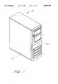
- FIG. 1is a perspective view of a computer incorporating an improved disk drive cooling system of the present invention
- FIG. 2is a perspective view of a computer with a front panel and side door removed, showing the internal chassis defining a disk drive cage;
- FIG. 3is a cut-away perspective view of the drive cage, showing a ventilated backplane utilized in the present invention
- FIG. 4is a side view of the computer chassis of FIG. 2;
- FIG. 5is a plan view of the backplane, showing disk drive connectors and ventilation apertures therebetween;
- FIG. 6is an exploded view of a fan assembly and plenum adapted to mount to the ventilated backplane shown in FIG. 5;
- FIG. 7is a side elevational view of the computer chassis, showing the fan assembly of FIG. 6 mounted to the ventilated backplane;
- FIG. 8is a rear elevational view of an alternative fan housing configured to mount to the ventilated backplane
- FIG. 9is a right side elevational view of the fan housing of FIG. 8;
- FIG. 10is a left side elevational view of the fan housing of FIG. 8;
- FIG. 11is a top plan view of the fan housing of FIG. 8;
- FIG. 12is a front elevational view of the fan housing of FIG. 8;
- FIG. 13is a cross-sectional view of the fan housing of FIG. 8 taken along line 13--13;
- FIG. 14is a cross-sectional view of the fan housing of FIG. 8 taken along line 14--14;
- FIG. 15is a plan view of an alternative backplane for use with the alternative fan housing of FIGS. 8-14, showing disk drive connectors and ventilation apertures therebetween.
- FIG. 1illustrates an exemplary computer system 20 into which the present invention can be incorporated.
- the computer system 20may be of a variety of types, but in the present example is shown as a server system which features a plurality of hard disk drives configured as a RAID system and farther includes one or more floppy drives, CD ROM drives, tape drives, and the like.
- the computer system 20is preferably enclosed within a so-called “tower" enclosure or cabinet, which has a height greater than the width of the front thereof and which further has a depth greater than the width of the front.
- the computer system 20includes a stylized front panel 22 having controls, indicators and access for one or more floppy disk drives, a CD ROM drive, etc. Further, the front panel 22 may be opened to provide access to the disk drives of the RAID subsystem therein.
- a side door 24is provided, which can be easily removed.
- the computer system 20is typically assembled such that components within the computer system 20 are easily accessible with the side door 24 removed.
- the side door 24 of the computer system 20has been removed to expose an inner sheet metal chassis 26.
- the computer system 20includes a plurality of inner bracings and mounting structures for the various components.
- the stylized front panel 22has also been removed to expose a planar front plate 28.
- the front plate 28includes a large rectangular opening 30 leading to one or more cavities defined within a drive cage 32.
- the drive cage 32comprises side walls 34 extending parallel to the side door 24, and a plurality of transverse horizontal shelves 36 provided with guides 38.
- the guides 38extend from the opening 30 inward and are sized to receive tray assemblies 40 for hard disk drives 42.
- the disk drives 42are mounted to the tray assemblies 40, which are vertically orientated and which slide along opposed guides 38 into the cavity defined within the drive cage 32.
- Each tray assembly 40includes a front pivoting bezel 44 having a handle 46 therein.
- the configuration of the tray assembly 40may be varied, but typically the bezel includes a lever-type latch which assists in inserting and removing the tray assembly 40 from the drive cage 32.
- each tray assembly 40aligns with a mating connector 48 provided on a first planar side 49a of a backplane 50.
- the disk drive 42mounts to the tray assembly 40 in a conventional manner and is electrically connected therethrough to the connector 47, as is well known in the art.
- the backplane 50defines an inner wall of the drive cage 32 and is securely fastened to the internal chassis 26. More particularly, the backplane 50 includes a plurality of through holes 51 through which threaded fasteners 52 mount into threaded holes within mounting brackets 54 of the chassis.
- One such fastener 52is illustrated in FIG. 3, although there are preferably at least six--two each at the corners of the backplane 50 and two at the midpoint of the side edges. The fasteners 52 also ground the backplane 50 to the chassis 26.
- the backplane 50is more clearly seen in FIGS. 3-5, and includes the first planar side 49a and a second, oppositely facing planar side 49b.
- the backplane 50includes a plurality of apertures 56 which provide air passages therethrough to ventilate the drive cage 32.
- the apertures 56comprise two parallel columns of horizontally oriented slots 56 having rounded ends.
- the apertures 56greatly enhance the cooling capacity of fans disposed around the drive cage 32. More particularly, the apertures 56 augment currently existing cooling configurations for the drive cage 32 by enhancing convective heat transfer from the drive cage 32.
- a fan assemblyis preferably attached to the backplane 50.
- the fan assembly 58comprises a plenum 59 securely fastened to the backplane 50.
- the plenum 59comprises a shallow box shape having four narrow sides 60 connected to a rear wall 61, with the opposite wall being open.
- the plenum 59is mounted with the open wail juxtaposed against the backplane 50, as shown.
- a circular fan aperture 62is formed in the rear wall 61 of the plenum.
- a fan 64 having a fan guard 66rigidly attaches to the rear wall 61 at the fan aperture 62.
- a pair of elongated foam strips 68are placed between the plenum 59 and the backplane 50.
- One of the sides 60 of the plenum 59includes a pair of hooks 70 adapted to fit within slots 72 formed in the backplane 50.
- the hooks 70are formed in the side 60 of the plenum 59 furthest from the side door 24.
- Upper and lower tabs 74extend from two of the other sides 60 at a location closer to the side door 24.
- the upper and lower tabs 74receive threaded fasteners 76 that extend into threaded holes 77 within the backplane 50.
- the plenum 59is thus relatively easy to install because the hooks 70 are positioned within the slots 72, and the fasteners 76 are simply inserted through the holes in the tab 74 and into the backplane 50. Likewise, removal of the plenum 59 is equally easy.
- the plenum 59is further provided with a pair of outwardly extending flanges 78 that contact the foam strips 68. The flanges 78 compress the foam strips 68 against the backplane 50 to reduce vibrations transmitted there between, and also to enhance a seal around the edges of connection between the plenum 59 and the backplane 50.
- the fan 64can either pull air from the interior of the plenum 59 or push air therein. In either case, air is forced between the first and second planar sides 49a, 49b through the passages defined by the apertures 56 in the backplane 50. If air is being pulled from the plenum 59, the hot air generated by the disk drives 42 within the drive cage 32 is exhausted through the fan 64 into the cabinet of the computer 20, which typically has one or more other cooling fans in communication with the ambient atmosphere. Alternatively, if air is pushed into the plenum 59 by the fan 64, cool air is forced into the drive cage 32, which then displaces the hot air there within through any of a plurality of vents surrounding the drive cage, such as for example, through vents in the front panel 22. Typically, the fan 64 runs continuously during operation of the computer system 20; however, the fan 64 may also be responsive to a temperature sensor (not shown) provided within the drive cage 32 to thereby operate only when the drive cage temperature exceeds a predetermined threshold.
- a temperature sensornot shown
- FIGS. 8-14illustrate an alternative fan housing 82 which attaches to an alternative ventilated backplane 83, shown in FIG. 15.
- the fan 64was attached externally to the plenum 59. This arrangement is preferred if space within the computer system 20 is available because the efficiency of the fan is increased by the seals provided by attachment between the plenum 59 and the backplane 50. In some computer systems, however, space is limited. Thus, the alternative fan housing 82 may be used.
- the alternative fan housing 82comprises a plurality of sides 84 and a rear wail 86.
- the rear wall 86includes one or more fan grids 88, two of which are shown in FIGS. 8 and 12.
- the fan housing 82is provided with a pair of outwardly extending hooks 90 on one side.
- the hooks 90are adapted to fit within slots 92 in the backplane 83.
- the hooks 90are provided on the side of the fan housing 82 away from the side door 24.
- a pair of cantilevered latches 94including outward detents 96, are provided.
- the latches 94are sized to fit within slots 97 formed in the backplane 83.
- the hooks 90are fitted within the slots 92, and the cantilevered latches 94 then snap into the slots 97.
- the outward detents 96hold the fan housing 82 to the backplane 83, and the housing can be released by simply pressing the latches 94 inward.
- the alternative fan housing 82has a lower profile than the first-described fan assembly 58 due to the mounting configuration of the fan within the housing 82.
- a plurality of locating pins 98extend from an inner face of the rear wall 86.
- the fan 64is typically provided with holes for mating with the pins 98, and is pressed into the area between the sides 84 biasing apart a pair of cantilevered fan latches 100.
- the fan latches 100include inward detents 102 which retain the fan within the housing 82.
- the fan or fans 64either pull or push air through the ventilation apertures 56.
- a single fan 64may be provided within the housing 82, in which case one of the fan grids 88 shown in FIG. 8 is replaced with a solid wall.
- a pair of fans 64are provided within the housing 82 and work continuously during operation of the computer system 20.
- the operation of the fans 64may be triggered by a temperature sensor (not shown) within the drive cage 32.
Landscapes
- Engineering & Computer Science (AREA)
- Theoretical Computer Science (AREA)
- Human Computer Interaction (AREA)
- Physics & Mathematics (AREA)
- General Engineering & Computer Science (AREA)
- General Physics & Mathematics (AREA)
- Cooling Or The Like Of Electrical Apparatus (AREA)
Abstract
Description
Claims (8)
Priority Applications (1)
| Application Number | Priority Date | Filing Date | Title |
|---|---|---|---|
| US08/556,668US5680295A (en) | 1995-11-13 | 1995-11-13 | Ventilated backplane for mounting disk drives in computer systems |
Applications Claiming Priority (1)
| Application Number | Priority Date | Filing Date | Title |
|---|---|---|---|
| US08/556,668US5680295A (en) | 1995-11-13 | 1995-11-13 | Ventilated backplane for mounting disk drives in computer systems |
Publications (1)
| Publication Number | Publication Date |
|---|---|
| US5680295Atrue US5680295A (en) | 1997-10-21 |
Family
ID=24222334
Family Applications (1)
| Application Number | Title | Priority Date | Filing Date |
|---|---|---|---|
| US08/556,668Expired - LifetimeUS5680295A (en) | 1995-11-13 | 1995-11-13 | Ventilated backplane for mounting disk drives in computer systems |
Country Status (1)
| Country | Link |
|---|---|
| US (1) | US5680295A (en) |
Cited By (57)
| Publication number | Priority date | Publication date | Assignee | Title |
|---|---|---|---|---|
| US5867369A (en)* | 1997-07-15 | 1999-02-02 | Sun Microsystems, Inc. | Rugged computer housing |
| US5886639A (en)* | 1996-02-15 | 1999-03-23 | Inclose Design, Inc. | Memory storage device housing and cooling device |
| US5949645A (en)* | 1997-06-02 | 1999-09-07 | Northern Telecom Limited | Electronic unit |
| US5991852A (en)* | 1996-10-28 | 1999-11-23 | Mti Technology Corporation | Cache ram using a secondary controller and switching circuit and improved chassis arrangement |
| US6011688A (en)* | 1997-06-04 | 2000-01-04 | Hewlett Packard Co. | Compact apparatus for cooling a plurality of circuit packs arranged with a cage |
| US6058019A (en)* | 1998-05-21 | 2000-05-02 | International Business Machines Corporation | Electronic circuit card assembly having confined ground path return |
| US6101459A (en)* | 1997-08-15 | 2000-08-08 | Compaq Computer Corporation | System and associated method for cooling components within a computer system |
| WO2000047029A1 (en)* | 1999-02-03 | 2000-08-10 | Lockheed Martin Corporation | Electronic packaging system |
| US6108198A (en)* | 1997-09-19 | 2000-08-22 | Mitac International Corp. | Modular computer device |
| US6144555A (en)* | 1998-04-09 | 2000-11-07 | Telefonaktiebolaget Lm Ericsson | Protective structure |
| US6152819A (en)* | 1998-04-10 | 2000-11-28 | Fanuc Ltd. | Numerical control device |
| US6172876B1 (en)* | 1997-11-14 | 2001-01-09 | Elsag International N.V. | Modular I/O assembly system |
| US6198628B1 (en) | 1998-11-24 | 2001-03-06 | Unisys Corporation | Parallel cooling of high power devices in a serially cooled evironment |
| US6233148B1 (en) | 1999-09-21 | 2001-05-15 | Tsan Jung Shen | Hard disk drive heat dissipation device |
| US6236564B1 (en)* | 2000-04-13 | 2001-05-22 | Enlight Corporation | Detachable fan rack mounting structure |
| US6242691B1 (en)* | 1999-02-03 | 2001-06-05 | Lockheed Martin Corporation | Electronic packaging and method of packaging |
| US6285546B1 (en)* | 1998-12-03 | 2001-09-04 | Hitachi, Ltd. | Mounting structure for electronic device |
| US6293636B1 (en) | 1999-12-30 | 2001-09-25 | Gateway, Inc. | Device retention assembly |
| US6307742B1 (en)* | 2000-04-19 | 2001-10-23 | Hewlett-Packard Company | Computer with readily accessible motherboard |
| US6322042B1 (en)* | 2000-07-19 | 2001-11-27 | Lite-On Enclosure Inc. | Extracted and positioning device of a fan |
| US6330156B1 (en) | 1999-08-10 | 2001-12-11 | Micron Technology, Inc. | Card support and cooler bracket |
| US6359779B1 (en)* | 1999-04-05 | 2002-03-19 | Western Digital Ventures, Inc. | Integrated computer module with airflow accelerator |
| US6430041B1 (en) | 1999-10-20 | 2002-08-06 | Micronpc, Llc | Computer cooling system and method |
| US6456489B1 (en) | 2000-05-25 | 2002-09-24 | Gateway, Inc. | Device retention apparatus |
| US6549397B1 (en)* | 2000-05-26 | 2003-04-15 | Hewlett-Packard Company | Tower computer with low center of gravity |
| US6567266B2 (en)* | 2001-05-16 | 2003-05-20 | Hewlett-Packard Development Company, L.P. | Foam systems for protecting disk drives from mechanical disturbances |
| US6603661B2 (en)* | 2001-12-14 | 2003-08-05 | Hewlett-Packard Development Company, L.P. | Universal fan cage for hot-pluggable fans |
| US6619766B1 (en) | 1999-10-12 | 2003-09-16 | Gateway, Inc. | Device mounting and retention assembly |
| US6639795B1 (en)* | 2002-02-15 | 2003-10-28 | Steve Cooper | Flow through butterfly backpane |
| US6661657B1 (en)* | 2002-02-14 | 2003-12-09 | Mercury Computer Systems, Inc. | Circuit board assembly for use in a central inlet chassis configuration |
| US20040001328A1 (en)* | 2002-06-26 | 2004-01-01 | Lee Chun Liang | Back Plane Structure for SCSI |
| US20040005855A1 (en)* | 2002-04-29 | 2004-01-08 | Giraldo Mike D. | Modular fan system |
| US6690575B1 (en) | 2002-02-14 | 2004-02-10 | Mercury Computer Systems, Inc. | Digital data processor chassis with flow balanced air intake into multiple circuit board assemblies |
| US6759588B1 (en) | 2002-02-14 | 2004-07-06 | Mercury Computer Systems, Inc. | Circuit board assembly with a combination thermal, shock, vibration, and/or electromagnetic compatibility cover |
| US6781831B1 (en) | 2002-02-14 | 2004-08-24 | Mercury Computer Systems, Inc. | Card-cage with integrated control and shaping of flow resistance curve for multiple plenum chambers |
| US6826048B1 (en) | 2003-09-18 | 2004-11-30 | Hewlett-Packard Development Company, L.P. | Method and apparatus for securing a fan within a device |
| US6827583B2 (en)* | 2000-09-18 | 2004-12-07 | General Instrument Corporation | Electronic connection system |
| US20040264129A1 (en)* | 2003-06-27 | 2004-12-30 | Lehman Bret W. | Vibration isolation of computing device heat sink fans from attached fan shrouds and heat sinks |
| US6879486B1 (en) | 2002-02-14 | 2005-04-12 | Mercury Computer Systems, Inc. | Central inlet circuit board assembly |
| US6885550B1 (en) | 1999-08-26 | 2005-04-26 | Axxion Group Corporation | Screw less clip mounted computer drive |
| US20050117308A1 (en)* | 2003-11-28 | 2005-06-02 | Paul Harman | Electronic apparatus with a storage device |
| US20050128707A1 (en)* | 2003-12-12 | 2005-06-16 | Sanders David K. | Device for removing heat from electrical equipment |
| US6989993B2 (en)* | 1998-08-05 | 2006-01-24 | Yazaki Corporation | Audio rack for a vehicle |
| US7042722B2 (en) | 2003-05-29 | 2006-05-09 | Hitachi, Ltd. | Electronic equipment |
| WO2007053139A1 (en)* | 2005-10-31 | 2007-05-10 | Hewlett-Packard Development Company L.P. | A ventilated casing for an electronic device |
| US20070119049A1 (en)* | 2005-11-29 | 2007-05-31 | Seiko Epson Corporation | Robot control device and robot system |
| US20070285895A1 (en)* | 2004-02-23 | 2007-12-13 | Infineon Technologies Ag | Cooling System For Device Having Power Semiconductors And Method For Cooling The Device |
| US20080113603A1 (en)* | 2006-10-19 | 2008-05-15 | Atallah Jean G | Computer system cooling system |
| US20090059516A1 (en)* | 2007-08-30 | 2009-03-05 | Hong Fu Jin Precision Industry (Shenzhen) Co., Ltd. | Computer |
| US20090103414A1 (en)* | 2007-10-19 | 2009-04-23 | Hewlett-Packard Development Company, L.P. | Cooling in high-density storage systems |
| US7570484B1 (en)* | 2006-10-30 | 2009-08-04 | American Megatrends, Inc. | System and apparatus for removably mounting hard disk drives |
| US20100033917A1 (en)* | 2008-08-08 | 2010-02-11 | Inventec Corporation | Computer |
| US20110149507A1 (en)* | 2009-12-23 | 2011-06-23 | Hong Fu Jin Precision Industry (Shenzhen) Co., Ltd | Computer system |
| US9681579B2 (en) | 2015-06-12 | 2017-06-13 | International Business Machines Corporation | Cooling system for electronic devices employing adjacent fan cages with interflow passages |
| US9942798B2 (en)* | 2004-07-16 | 2018-04-10 | Virginia Innovation Sciences, Inc. | Method and system for efficient communication |
| US20230237984A1 (en)* | 2022-01-25 | 2023-07-27 | Dell Products L.P. | System and method for reducing acoustic energy near hdd systems |
| US20230307009A1 (en)* | 2020-12-01 | 2023-09-28 | Huawei Technologies Co., Ltd. | Hard Drive Backplane Assembly and Electronic Device |
Citations (9)
| Publication number | Priority date | Publication date | Assignee | Title |
|---|---|---|---|---|
| US4860163A (en)* | 1988-08-05 | 1989-08-22 | American Telephone And Telegraph Company | Communication equipment cabinet cooling arrangement |
| US4918572A (en)* | 1988-12-27 | 1990-04-17 | Motorola Computer X, Inc. | Modular electronic package |
| US4967311A (en)* | 1987-07-22 | 1990-10-30 | Tandem Computers Incorporated | Electronic module interconnection system |
| US5173845A (en)* | 1989-12-26 | 1992-12-22 | Star Technologies, Inc. | High density frontplane interconnection system |
| US5313699A (en)* | 1989-09-22 | 1994-05-24 | Unisys Corporation | Methods for packaging circuit boards |
| US5343357A (en)* | 1992-08-26 | 1994-08-30 | Data General Corp. | Disk array subsystem for use in a data processing system |
| US5513068A (en)* | 1993-06-01 | 1996-04-30 | Seanix Technology Inc. | Computer case with adjustable drive housing for interchangeable desktop/tower configuration and control panel attachable to the drive housing |
| US5536176A (en)* | 1994-05-25 | 1996-07-16 | Tandem Computers Incorporated | Flexible bus routing structure |
| US5557506A (en)* | 1995-03-31 | 1996-09-17 | Alantec | Expandable data processing chassis and method of assembly thereof |
- 1995
- 1995-11-13USUS08/556,668patent/US5680295A/ennot_activeExpired - Lifetime
Patent Citations (9)
| Publication number | Priority date | Publication date | Assignee | Title |
|---|---|---|---|---|
| US4967311A (en)* | 1987-07-22 | 1990-10-30 | Tandem Computers Incorporated | Electronic module interconnection system |
| US4860163A (en)* | 1988-08-05 | 1989-08-22 | American Telephone And Telegraph Company | Communication equipment cabinet cooling arrangement |
| US4918572A (en)* | 1988-12-27 | 1990-04-17 | Motorola Computer X, Inc. | Modular electronic package |
| US5313699A (en)* | 1989-09-22 | 1994-05-24 | Unisys Corporation | Methods for packaging circuit boards |
| US5173845A (en)* | 1989-12-26 | 1992-12-22 | Star Technologies, Inc. | High density frontplane interconnection system |
| US5343357A (en)* | 1992-08-26 | 1994-08-30 | Data General Corp. | Disk array subsystem for use in a data processing system |
| US5513068A (en)* | 1993-06-01 | 1996-04-30 | Seanix Technology Inc. | Computer case with adjustable drive housing for interchangeable desktop/tower configuration and control panel attachable to the drive housing |
| US5536176A (en)* | 1994-05-25 | 1996-07-16 | Tandem Computers Incorporated | Flexible bus routing structure |
| US5557506A (en)* | 1995-03-31 | 1996-09-17 | Alantec | Expandable data processing chassis and method of assembly thereof |
Cited By (75)
| Publication number | Priority date | Publication date | Assignee | Title |
|---|---|---|---|---|
| US5886639A (en)* | 1996-02-15 | 1999-03-23 | Inclose Design, Inc. | Memory storage device housing and cooling device |
| US5991852A (en)* | 1996-10-28 | 1999-11-23 | Mti Technology Corporation | Cache ram using a secondary controller and switching circuit and improved chassis arrangement |
| US5949645A (en)* | 1997-06-02 | 1999-09-07 | Northern Telecom Limited | Electronic unit |
| US6011688A (en)* | 1997-06-04 | 2000-01-04 | Hewlett Packard Co. | Compact apparatus for cooling a plurality of circuit packs arranged with a cage |
| US5867369A (en)* | 1997-07-15 | 1999-02-02 | Sun Microsystems, Inc. | Rugged computer housing |
| US6101459A (en)* | 1997-08-15 | 2000-08-08 | Compaq Computer Corporation | System and associated method for cooling components within a computer system |
| US6108198A (en)* | 1997-09-19 | 2000-08-22 | Mitac International Corp. | Modular computer device |
| US6172876B1 (en)* | 1997-11-14 | 2001-01-09 | Elsag International N.V. | Modular I/O assembly system |
| US6144555A (en)* | 1998-04-09 | 2000-11-07 | Telefonaktiebolaget Lm Ericsson | Protective structure |
| US6152819A (en)* | 1998-04-10 | 2000-11-28 | Fanuc Ltd. | Numerical control device |
| US6058019A (en)* | 1998-05-21 | 2000-05-02 | International Business Machines Corporation | Electronic circuit card assembly having confined ground path return |
| US6989993B2 (en)* | 1998-08-05 | 2006-01-24 | Yazaki Corporation | Audio rack for a vehicle |
| US6198628B1 (en) | 1998-11-24 | 2001-03-06 | Unisys Corporation | Parallel cooling of high power devices in a serially cooled evironment |
| US6285546B1 (en)* | 1998-12-03 | 2001-09-04 | Hitachi, Ltd. | Mounting structure for electronic device |
| WO2000047029A1 (en)* | 1999-02-03 | 2000-08-10 | Lockheed Martin Corporation | Electronic packaging system |
| US6242691B1 (en)* | 1999-02-03 | 2001-06-05 | Lockheed Martin Corporation | Electronic packaging and method of packaging |
| US6359779B1 (en)* | 1999-04-05 | 2002-03-19 | Western Digital Ventures, Inc. | Integrated computer module with airflow accelerator |
| US6330156B1 (en) | 1999-08-10 | 2001-12-11 | Micron Technology, Inc. | Card support and cooler bracket |
| US7212411B2 (en) | 1999-08-26 | 2007-05-01 | Axxion Group Corporation | Screwless clip mounted computer drive |
| US6885550B1 (en) | 1999-08-26 | 2005-04-26 | Axxion Group Corporation | Screw less clip mounted computer drive |
| US6233148B1 (en) | 1999-09-21 | 2001-05-15 | Tsan Jung Shen | Hard disk drive heat dissipation device |
| US6619766B1 (en) | 1999-10-12 | 2003-09-16 | Gateway, Inc. | Device mounting and retention assembly |
| US6430041B1 (en) | 1999-10-20 | 2002-08-06 | Micronpc, Llc | Computer cooling system and method |
| US6293636B1 (en) | 1999-12-30 | 2001-09-25 | Gateway, Inc. | Device retention assembly |
| US6236564B1 (en)* | 2000-04-13 | 2001-05-22 | Enlight Corporation | Detachable fan rack mounting structure |
| US6307742B1 (en)* | 2000-04-19 | 2001-10-23 | Hewlett-Packard Company | Computer with readily accessible motherboard |
| US6456489B1 (en) | 2000-05-25 | 2002-09-24 | Gateway, Inc. | Device retention apparatus |
| US6549397B1 (en)* | 2000-05-26 | 2003-04-15 | Hewlett-Packard Company | Tower computer with low center of gravity |
| US6322042B1 (en)* | 2000-07-19 | 2001-11-27 | Lite-On Enclosure Inc. | Extracted and positioning device of a fan |
| US6827583B2 (en)* | 2000-09-18 | 2004-12-07 | General Instrument Corporation | Electronic connection system |
| US6567266B2 (en)* | 2001-05-16 | 2003-05-20 | Hewlett-Packard Development Company, L.P. | Foam systems for protecting disk drives from mechanical disturbances |
| US6603661B2 (en)* | 2001-12-14 | 2003-08-05 | Hewlett-Packard Development Company, L.P. | Universal fan cage for hot-pluggable fans |
| US6759588B1 (en) | 2002-02-14 | 2004-07-06 | Mercury Computer Systems, Inc. | Circuit board assembly with a combination thermal, shock, vibration, and/or electromagnetic compatibility cover |
| US6690575B1 (en) | 2002-02-14 | 2004-02-10 | Mercury Computer Systems, Inc. | Digital data processor chassis with flow balanced air intake into multiple circuit board assemblies |
| US6781831B1 (en) | 2002-02-14 | 2004-08-24 | Mercury Computer Systems, Inc. | Card-cage with integrated control and shaping of flow resistance curve for multiple plenum chambers |
| US6661657B1 (en)* | 2002-02-14 | 2003-12-09 | Mercury Computer Systems, Inc. | Circuit board assembly for use in a central inlet chassis configuration |
| US6879486B1 (en) | 2002-02-14 | 2005-04-12 | Mercury Computer Systems, Inc. | Central inlet circuit board assembly |
| US6639795B1 (en)* | 2002-02-15 | 2003-10-28 | Steve Cooper | Flow through butterfly backpane |
| US20040005855A1 (en)* | 2002-04-29 | 2004-01-08 | Giraldo Mike D. | Modular fan system |
| US6896611B2 (en)* | 2002-04-29 | 2005-05-24 | Hewlett-Packard Development Company, L.P. | Modular fan system |
| US6835894B2 (en)* | 2002-06-26 | 2004-12-28 | Inventec Corporation | Back plane structure for SCSI |
| US20040001328A1 (en)* | 2002-06-26 | 2004-01-01 | Lee Chun Liang | Back Plane Structure for SCSI |
| US7042722B2 (en) | 2003-05-29 | 2006-05-09 | Hitachi, Ltd. | Electronic equipment |
| US6924980B2 (en) | 2003-06-27 | 2005-08-02 | International Business Machines Corporation | Vibration isolation of computing device heat sink fans from attached fan shrouds and heat sinks |
| US20040264129A1 (en)* | 2003-06-27 | 2004-12-30 | Lehman Bret W. | Vibration isolation of computing device heat sink fans from attached fan shrouds and heat sinks |
| US6826048B1 (en) | 2003-09-18 | 2004-11-30 | Hewlett-Packard Development Company, L.P. | Method and apparatus for securing a fan within a device |
| US20050117308A1 (en)* | 2003-11-28 | 2005-06-02 | Paul Harman | Electronic apparatus with a storage device |
| US7307843B2 (en)* | 2003-11-28 | 2007-12-11 | Thomson Licensing | Electronic apparatus with a storage device |
| US20050128707A1 (en)* | 2003-12-12 | 2005-06-16 | Sanders David K. | Device for removing heat from electrical equipment |
| US7158379B2 (en)* | 2003-12-12 | 2007-01-02 | Cisco Technology, Inc. | Device for removing heat from a power connector |
| US7688592B2 (en)* | 2004-02-23 | 2010-03-30 | Infineon Technologies Ag | Cooling system for devices having power semiconductors and method for cooling the device |
| US20070285895A1 (en)* | 2004-02-23 | 2007-12-13 | Infineon Technologies Ag | Cooling System For Device Having Power Semiconductors And Method For Cooling The Device |
| US9942798B2 (en)* | 2004-07-16 | 2018-04-10 | Virginia Innovation Sciences, Inc. | Method and system for efficient communication |
| WO2007053139A1 (en)* | 2005-10-31 | 2007-05-10 | Hewlett-Packard Development Company L.P. | A ventilated casing for an electronic device |
| US8599555B2 (en)* | 2005-11-29 | 2013-12-03 | Seiko Epson Corporation | Robot control device and robot system |
| US20070119049A1 (en)* | 2005-11-29 | 2007-05-31 | Seiko Epson Corporation | Robot control device and robot system |
| US20100262285A1 (en)* | 2005-11-29 | 2010-10-14 | Seiko Epson Corporation | Robot control device and robot system |
| US7769489B2 (en)* | 2005-11-29 | 2010-08-03 | Seiko Epson Corporation | Robot control device and robot system |
| US20080113603A1 (en)* | 2006-10-19 | 2008-05-15 | Atallah Jean G | Computer system cooling system |
| US8199481B2 (en) | 2006-10-30 | 2012-06-12 | American Megatrends, Inc. | System and apparatus for removably mounting hard disk drives |
| US7570484B1 (en)* | 2006-10-30 | 2009-08-04 | American Megatrends, Inc. | System and apparatus for removably mounting hard disk drives |
| US7948748B1 (en)* | 2006-10-30 | 2011-05-24 | American Megatrends, Inc. | System and apparatus for removably mounting hard disk drives |
| US20110188196A1 (en)* | 2006-10-30 | 2011-08-04 | American Megatrends, Inc. | System and apparatus for removably mounting hard disk drives |
| US20090059516A1 (en)* | 2007-08-30 | 2009-03-05 | Hong Fu Jin Precision Industry (Shenzhen) Co., Ltd. | Computer |
| US7742296B2 (en)* | 2007-08-30 | 2010-06-22 | Hong Fu Jin Precision Industry (Shenzhen) Co., Ltd. | Computer having apparatuses for cooling elements |
| US20090103414A1 (en)* | 2007-10-19 | 2009-04-23 | Hewlett-Packard Development Company, L.P. | Cooling in high-density storage systems |
| US8898682B2 (en)* | 2007-10-19 | 2014-11-25 | Hewlett-Packard Development Company, Lp. | Cooling in high-density storage systems |
| US20100033917A1 (en)* | 2008-08-08 | 2010-02-11 | Inventec Corporation | Computer |
| US20110149507A1 (en)* | 2009-12-23 | 2011-06-23 | Hong Fu Jin Precision Industry (Shenzhen) Co., Ltd | Computer system |
| US9681579B2 (en) | 2015-06-12 | 2017-06-13 | International Business Machines Corporation | Cooling system for electronic devices employing adjacent fan cages with interflow passages |
| US10257957B2 (en) | 2015-06-12 | 2019-04-09 | International Business Machines Corporation | Cooling system for electronic devices employing adjacent fan cages with interflow passages |
| US20230307009A1 (en)* | 2020-12-01 | 2023-09-28 | Huawei Technologies Co., Ltd. | Hard Drive Backplane Assembly and Electronic Device |
| US12347464B2 (en)* | 2020-12-01 | 2025-07-01 | Huawei Technoloiges Co., Ltd. | Hard drive backplane assembly and electronic device |
| US20230237984A1 (en)* | 2022-01-25 | 2023-07-27 | Dell Products L.P. | System and method for reducing acoustic energy near hdd systems |
| US12308008B2 (en)* | 2022-01-25 | 2025-05-20 | Dell Products L.P. | System and method for reducing acoustic energy near HDD systems |
Similar Documents
| Publication | Publication Date | Title |
|---|---|---|
| US5680295A (en) | Ventilated backplane for mounting disk drives in computer systems | |
| US7046470B2 (en) | Data storage system | |
| US8432689B2 (en) | Rack mounted computer system | |
| US7256995B2 (en) | Electronics module | |
| US7236370B2 (en) | Computer rack with cluster modules | |
| EP0442640B1 (en) | Data storage system with device dependent flow of cooling air | |
| US5526228A (en) | Computer system unit with acoustic dampening cooling fan shroud panel | |
| EP0896697B1 (en) | Personal computer enclosure with peripheral device mounting system | |
| US6437980B1 (en) | Low profile high density rack mountable enclosure with superior cooling and highly accessible re-configurable components | |
| US4774631A (en) | Cooling structure of electronic equipment rack | |
| US6667891B2 (en) | Computer chassis for dual offset opposing main boards | |
| US6061237A (en) | Computer with an improved cooling system and a method for cooling a computer | |
| US6115250A (en) | Computer and an assembly and method for cooling a computer | |
| US6958906B2 (en) | Method and apparatus for cooling a modular computer system with dual path airflow | |
| EP0442642B1 (en) | Multi unit electrical apparatus with forced air cooling | |
| US6690576B2 (en) | Externally mounted on-line replaceable fan module | |
| US6950304B2 (en) | Disk array device | |
| US6606242B2 (en) | Universal adapter bracket for mounting electronic devices | |
| JPH0246965B2 (en) | ||
| US4985803A (en) | Housing for a multi-board electronic module for a programmable controller system | |
| US20030117782A1 (en) | Electronic circuits | |
| CN217982282U (en) | Case and server | |
| EP1157385B1 (en) | Computer system with dummy drive for optimal cooling efficiency | |
| JP2564704B2 (en) | Storage disk module and collective storage disk device using the same | |
| JP2799183B2 (en) | Collective disk storage device |
Legal Events
| Date | Code | Title | Description |
|---|---|---|---|
| AS | Assignment | Owner name:AST RESEARCH, INC., CALIFORNIA Free format text:ASSIGNMENT OF ASSIGNORS INTEREST;ASSIGNORS:LE, BAO G.;KABENJIAN, GREGORY V.;REEL/FRAME:007843/0433;SIGNING DATES FROM 19960222 TO 19960223 | |
| STCF | Information on status: patent grant | Free format text:PATENTED CASE | |
| AS | Assignment | Owner name:AST RESEARCH, INC., CALIFORNIA Free format text:SECURITY INTEREST;ASSIGNOR:AST COMPUTERS, LLC;REEL/FRAME:009703/0089 Effective date:19990108 | |
| FPAY | Fee payment | Year of fee payment:4 | |
| AS | Assignment | Owner name:SAMSUNG ELECTRONICS AMERICA, INC., NEW JERSEY Free format text:ASSIGNMENT OF ASSIGNORS INTEREST;ASSIGNOR:ARI SERVICE, INC.;REEL/FRAME:012665/0878 Effective date:20020318 Owner name:ARI SERVICE, INC., CALIFORNIA Free format text:AGREEMENT OF MERGER AST RESEARCH, INC., WITH AND INTO ARI SERVICE, INC.;ASSIGNORS:AST RESEARCH, INC., A DELAWARE CORPORATION;ARI SERVICE, INC., A CALIFORNIA CORPORATION;REEL/FRAME:012691/0384 Effective date:20000330 | |
| AS | Assignment | Owner name:SAMSUNG ELECTRONICS CO., LTD., KOREA, REPUBLIC OF Free format text:ASSIGNMENT OF ASSIGNORS INTEREST;ASSIGNOR:SAMSUNG ELECTRONICS AMERICA, INC.;REEL/FRAME:012721/0141 Effective date:20020326 | |
| AS | Assignment | Owner name:AST COMPUTERS, LLC, CALIFORNIA Free format text:RELEASE OF SECURITY INTEREST;ASSIGNOR:ARI SERVICE, INC., AS SUCCESSOR IN INTEREST BY MERGER TO AST RESEARCH, INC.;REEL/FRAME:012852/0320 Effective date:20020503 | |
| FEPP | Fee payment procedure | Free format text:PAYOR NUMBER ASSIGNED (ORIGINAL EVENT CODE: ASPN); ENTITY STATUS OF PATENT OWNER: LARGE ENTITY | |
| FPAY | Fee payment | Year of fee payment:8 | |
| AS | Assignment | Owner name:JINGPIN TECHNOLOGIES, LLC, DELAWARE Free format text:ASSIGNMENT OF ASSIGNORS INTEREST;ASSIGNOR:SAMSUNG ELECTRONICS CO., LTD.;REEL/FRAME:018883/0845 Effective date:20070122 | |
| FEPP | Fee payment procedure | Free format text:PAYER NUMBER DE-ASSIGNED (ORIGINAL EVENT CODE: RMPN); ENTITY STATUS OF PATENT OWNER: LARGE ENTITY Free format text:PAYOR NUMBER ASSIGNED (ORIGINAL EVENT CODE: ASPN); ENTITY STATUS OF PATENT OWNER: LARGE ENTITY | |
| FPAY | Fee payment | Year of fee payment:12 |