US5678683A - Conveyor chain with sealed plug hinge pin retention system - Google Patents
Conveyor chain with sealed plug hinge pin retention systemDownload PDFInfo
- Publication number
- US5678683A US5678683AUS08/596,588US59658896AUS5678683AUS 5678683 AUS5678683 AUS 5678683AUS 59658896 AUS59658896 AUS 59658896AUS 5678683 AUS5678683 AUS 5678683A
- Authority
- US
- United States
- Prior art keywords
- eyes
- conveyor element
- conveyor
- series
- openings
- Prior art date
- Legal status (The legal status is an assumption and is not a legal conclusion. Google has not performed a legal analysis and makes no representation as to the accuracy of the status listed.)
- Expired - Fee Related
Links
Images

Classifications
- B—PERFORMING OPERATIONS; TRANSPORTING
- B65—CONVEYING; PACKING; STORING; HANDLING THIN OR FILAMENTARY MATERIAL
- B65G—TRANSPORT OR STORAGE DEVICES, e.g. CONVEYORS FOR LOADING OR TIPPING, SHOP CONVEYOR SYSTEMS OR PNEUMATIC TUBE CONVEYORS
- B65G17/00—Conveyors having an endless traction element, e.g. a chain, transmitting movement to a continuous or substantially-continuous load-carrying surface or to a series of individual load-carriers; Endless-chain conveyors in which the chains form the load-carrying surface
- B65G17/06—Conveyors having an endless traction element, e.g. a chain, transmitting movement to a continuous or substantially-continuous load-carrying surface or to a series of individual load-carriers; Endless-chain conveyors in which the chains form the load-carrying surface having a load-carrying surface formed by a series of interconnected, e.g. longitudinal, links, plates, or platforms
- B65G17/08—Conveyors having an endless traction element, e.g. a chain, transmitting movement to a continuous or substantially-continuous load-carrying surface or to a series of individual load-carriers; Endless-chain conveyors in which the chains form the load-carrying surface having a load-carrying surface formed by a series of interconnected, e.g. longitudinal, links, plates, or platforms the surface being formed by the traction element
- B—PERFORMING OPERATIONS; TRANSPORTING
- B65—CONVEYING; PACKING; STORING; HANDLING THIN OR FILAMENTARY MATERIAL
- B65G—TRANSPORT OR STORAGE DEVICES, e.g. CONVEYORS FOR LOADING OR TIPPING, SHOP CONVEYOR SYSTEMS OR PNEUMATIC TUBE CONVEYORS
- B65G2201/00—Indexing codes relating to handling devices, e.g. conveyors, characterised by the type of product or load being conveyed or handled
- B65G2201/02—Articles
- B—PERFORMING OPERATIONS; TRANSPORTING
- B65—CONVEYING; PACKING; STORING; HANDLING THIN OR FILAMENTARY MATERIAL
- B65G—TRANSPORT OR STORAGE DEVICES, e.g. CONVEYORS FOR LOADING OR TIPPING, SHOP CONVEYOR SYSTEMS OR PNEUMATIC TUBE CONVEYORS
- B65G2207/00—Indexing codes relating to constructional details, configuration and additional features of a handling device, e.g. Conveyors
- B65G2207/12—Chain pin retainers
Definitions
- the inventionrelates generally to belts, chains, or conveyors including a plurality of chain links or conveyor elements connected by a succession of hinge pins.
- the axial loads on a hinge pin in a conveyor chain or beltwere such as to encourage axial hinge pin migration out of or from its connecting function.
- the inventionrelates to arrangements for retaining conveyor hinge pins against axial migration.
- end plugswere retained in the links or conveyor elements by cantilever style barbed ends which were snap fitted into the openings in the end eyes of one of the connected links or elements so as thereby to releaseably prevent axial removal of the end plugs and to consequentially prevent axial hinge pin migration when such end plugs were assembled to the associated link or conveyor element.
- Such snap fittingpermitted end plug removal to an enable cleaning of the end plug and of the link joint or connection.
- the inventionprovides a conveyor comprising a first conveyor element including an end comprising a first series of eyes spaced from each other to define therebetween a series of spaces, having therein respective openings axially aligned with each other, and including an end eye, a second conveyor element including an end comprising a second series of eyes which are spaced from each other to define therebetween a series of spaces receiving the eyes of the first conveyor element, which extend into the spaces between the eyes of the first conveyor element, and which have therein respective openings axially aligned with respect to each other and axially aligned with respect to the openings of the eyes of the first conveyor element, a cylindrical hinge pin extending in the openings of the eyes of the first and second conveyor elements and including an end located adjacent the end eye of the first conveyor element, a plug fixed in the opening of the end eye of the first conveyor element and including an end in axial adjacent relation to the end of the hinge pin, and means on one of the plug and the end eye of the first conveyor element for providing a seal between the plug and the end eye
- the inventionalso provides a conveyor comprising a first conveyor element including an end comprising a first series of eyes spaced from each other to define therebetween a series of spaces and including a sub-series of centrally located eyes respectively including therein openings having a given diametric dimension and being axially aligned with respect to each other, a first end eye adjacently spaced from the sub-series of centrally located eyes and including therein an opening located in axial alignment with the openings of the sub-series of centrally located eyes, and a second end eye adjacently spaced from the sub-series of centrally located eyes and including therein an opening located in axial alignment with the openings of the sub-series of centrally located eyes, a second conveyor element including an end comprising a series of eyes spaced from each other to define therebetween a series of spaces receiving the eyes of the first conveyor element, extending into the spaces between the eyes of the first conveyor element, and having therein respective openings axially aligned with respect to each other and axially aligned with respect
- FIG. 1is an exploded fragmentary perspective view of a belt, track, chain, or conveyor including various of the features of the invention.
- FIG. 2is a broken-away enlarged view, in section, of a portion of the construction shown in FIG. 1.
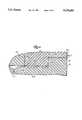
- FIG. 3is a further enlarged view, in section, of a portion of the construction shown in FIG. 2.
- FIG. 4is a view which is similar to FIG. 3 and which illustrates another embodiment of the invention.
- FIG. 1Shown in FIG. 1 is one embodiment of a belt, track, chain, or conveyor 11 which embodies various of the features of the invention and which includes first and second conveyor elements 13 and 15, respectively, a hinge pin 17 connecting the first and second conveyor elements 13 and 15, and first and second end plugs 19 and (see FIG. 2) 21, respectively, which are fixed in the first conveyor element 13 and which prevent axial migration of the hinge pin 17 and, at the same time, seal out dirt from entering between the first conveyor element 13 and the end plugs 19 and 21.
- the inventionis applicable to any type of track assembly or conveyor, and, except as noted hereinafter, the conveyor elements can take any conventional form and can be fabricated of any suitable material.
- the first conveyor element 13can be fabricated of any suitable substantially rigid material, such as thermoplastic material, and includes an end 23 comprising a series of eyes 25 transversely spaced from each other to define therebetween a series of spaces 27.
- the series of eyes 25includes a sub-series of centrally located eyes 31 respectively including therein openings or bores 33 having a given diametric dimension, and being axially aligned with respect to each other, as well as a first end eye 41 adjacently spaced transversely from one end of the other end of the sub-series of centrally located eyes 31 and including therein an opening or bore 43 located in axial alignment or registry with the openings 33 of the sub-series of centrally located eyes 31, and a second end eye 51 adjacently spaced from the other end of the sub-series of centrally located eyes 31 and including therein an opening or bore 53 located in axial alignment with the openings or bores 33 of the sub-series of centrally located eyes 31.
- the end eyes 41 and 51respectively also include inner surfaces 44 and 54 located adjacent the sub-series of centrally located eyes 31, and outer surfaces 45 and 55 which are located remotely from the sub-series of centrally located eyes 31 and which constitute portions of generally rectilinearly extending and laterally spaced sides of the conveyor 11.
- the openings or bores 33 of the sub-series of centrally located eyes 31can be cylindrical or can be elongated in the direction of travel of the conveyor 11 with an end of the opening or bore 33, in the direction of conveyor travel, being of semi-cylindrical shape.
- the openings or bores 43 and 53 in the end eyes 41 and 51are cylindrical and can be of the same diameter as, or of somewhat larger diameter than, the diameter of the openings or bores 33 in the sub-series of centrally located eyes 31.
- the openings or bores 43 and 53 in the end eyes 41 and 51respectively includes axially outer cylindrical portions 46 and 56 having diameters, and axially inner cylindrical portions 48 and 58 having diameters less than the diameters of the outer cylindrical portions 46 and 56.
- the openings or bores 43 and 53also respectively include shoulders 50 and 60 extending between the outer cylindrical portions 46 and 56 and the inner cylindrical portions 48 and 58 of the end plugs 19 and 21.
- the second conveyor element 15can be fabricated of any suitable substantially rigid material and includes an end 63 comprising a series of eyes 65 axially spaced from each other to define therebetween a series of spaces 67 receiving the centrally located eyes 31 of the adjacent first conveyor element 13.
- the eyes 65extend into the spaces 27 between the eyes of the adjacent first conveyor element 13 and have therein respective openings or bores 69 axially aligned with respect to each other and axially aligned with respect to the openings or bores of the eyes of the adjacent first conveyor element 13.
- the openings or bores 69can be cylindrical or can be elongated in the direction of conveyor travel, with an end of the opening or bore, in the direction of conveyor travel, being of semi-cylindrical shape and having a diametric dimension substantially equal to the diametric dimension of the openings or bores 33 of the sub-series of centrally located eyes 31 of the first conveyor element 13.
- the hinge pin 17can be fabricated of any suitable substantially rigid material, such as thermoplastic or steel, is cylindrical in shape, and includes a central portion 75 extending in the openings or bores 33 of the sub-series of centrally located eyes 31 of the first conveyor element 13 and in the openings or bores 69 of the eyes 65 of the second conveyor element 15 and having a diametric dimension slightly less than the diametric dimension of the openings or bores of the first and second conveyor elements 13 and 15.
- the hinge pin 17includes a first end 77 located adjacent the first end eye 41 of the first conveyor element 13, and a second end 79 located adjacent the second end eye 51 of the first conveyor element 13.
- the first and second end plugs 19 and 21are preferably fabricated from thermoplastic material, although other suitable material could be employed, are generally identical in shape, and are respectively fixed in the openings or bores 43 and 53 of the first and second end eyes 41 and 51 of the first conveyor element 13.
- the first and second end plugs 19 and 21respectively include ends 85 and 87 respectively located in axial adjacent relation to the first and second ends 77 and 79 of the hinge pin 17.
- first and second end plugs 19 and 21also respectively include first or axially outer cylindrical portions 91 and 93 having diameters which are slightly larger than the diameters of the outer cylindrical portions 46 and 56 of the openings or bores 43 and 53 in the end eyes 41 and 51, thus providing press fits when the first and second end plug 19 and 21 are respectively assembled into the end eyes 41 and 51.
- the first and second end plugs 19 and 21also respectively include second or axially inner cylindrical portions 95 and 97 having diameters slightly less than the diameters of the inner cylindrical portions 48 and 58 of the openings 43 and 53 of the first and second end eyes 41 and 51.
- end plugs 19 and 21respectively include shoulders 98 and 99 extending from the first cylindrical portions 91 and 93 to the second cylindrical portions 95 and 97, and being in engagement with the shoulders 50 and 60 of the first and second end eyes 41 and 51.
- Meansare also provided on one of the first end plug 19 and the first end eye 41 of the first conveyor element 13 and on one of the second end plug 21 and the second end eye 51 of the first conveyor element 13 for respectively providing seals between the first and second end plugs 19 and 21 and the first and second end eyes 41 and 51 of the first conveyor element 13.
- the seal providing meanscomprises, for each associated end plug and end eye, a first or axially inner and radially outwardly extending resilient membrane 101 extending from or fixed to the associated one of the end plugs 41 and 51 adjacent the axially inner end surfaces 44 and 54, and engaging the associated one of the end eyes, and a second or axially outer and radially outwardly extending resilient membrane 103 extending from or fixed to the associated one of the end plugs 19 and 21 adjacent the axially outer end surfaces 45 and 55, and engaging the associated one of the end eyes 41 and 51.
- the membranes 101 and 103are integral with and extend from the associated one of the end plugs 19 and 21 adjacent both the outer end surfaces 45 and 55 and the inner end surfaces 44 and 54. At least some of the advantages of the invention can be achieved when only one of the inner and outer seals or membranes 101 and 103 are employed.
- the membranes 101 and 103can be obtained by not removing the usual flash which normally occurs incident to molding in the area where adjacent dies meet. If desired, the edge surfaces of adjacent dies can be ground away to facilitate or promote inherent formation of a flash which can be employed as the membrane.
- the press fits between the end eyes 41 and 51 and the end plugs 19 and 21serve both to hold the end plugs 19 and 21 in place, thereby to prevent axial migration of the hinge pin 17, and to create a seal preventing bacteria from contaminating the chain. More specifically, when the end plugs 19 and 21 are installed in the end eyes 41 and 51, the end plugs 19 and 21 completely encompass the bores 43 and 53 in the end eyes 19 and 21. Furthermore, the membranes 101 and 103 provide a hermetic seal at the axial or lateral ends of the end plugs 19 and 21 to ensure that no bacteria will contaminate the plug area.
- the seal providing meanscan comprise resilient membranes 201 and 203 integrally extending from or fixed to the end eyes 41 and 51 adjacent either or both of the inner surfaces 44 and 54 and the outer surfaces 45 and 55 and engaging the associated one of the end plugs 19 and 21.
- the press fits of the end plugs 19 and 21 in the openings or bores 43 and 53 in the end eyes 41 and 51 and the seals obtained between the end plugs 19 and 21 and the end eyes 41 and 51 by use of the membranes 101 and 103 in the joint or connection or press fit between the end plugs 19 and 21 and the end eyes 41 and 51prevent contamination of the plug area, i.e., in the joint or connection between the end plugs 19 and 21 and the end eyes 41 and 43, and thereby avoid any need for cleansing thereof or disassembly.
Landscapes
- Engineering & Computer Science (AREA)
- Mechanical Engineering (AREA)
- Chain Conveyers (AREA)
- Separation Using Semi-Permeable Membranes (AREA)
- Containers And Plastic Fillers For Packaging (AREA)
Abstract
Description
Claims (10)
Priority Applications (14)
| Application Number | Priority Date | Filing Date | Title |
|---|---|---|---|
| US08/596,588US5678683A (en) | 1996-02-05 | 1996-02-05 | Conveyor chain with sealed plug hinge pin retention system |
| CA002191689ACA2191689C (en) | 1996-02-05 | 1996-11-29 | Conveyor chain with sealed plug hinge pin retention system |
| AU74200/96AAU708352B2 (en) | 1996-02-05 | 1996-12-05 | Conveyor chain with sealed plug hinge pin retention system |
| ZA9610283AZA9610283B (en) | 1996-02-05 | 1996-12-06 | Conveyor chain with sealed plug hinge pin retention system |
| EP96308902AEP0787665B1 (en) | 1996-02-05 | 1996-12-09 | Conveyor chain with sealed plug hinge pin retention system |
| DK96308902TDK0787665T3 (en) | 1996-02-05 | 1996-12-09 | Conveyor chain with hinge pin holding system with sealing plug |
| ES96308902TES2146362T3 (en) | 1996-02-05 | 1996-12-09 | CONVEYOR CHAIN WITH SEALED JOINT PIN PIN RETENTION SYSTEM. |
| DE69606849TDE69606849T2 (en) | 1996-02-05 | 1996-12-09 | Conveyor chain with sealing and retention plug for hinge pin |
| KR1019960076655AKR970061730A (en) | 1996-02-05 | 1996-12-30 | Conveyor chain with hinge pin retaining system by sealed plug |
| CN97100388ACN1109639C (en) | 1996-02-05 | 1997-01-21 | Conveyer chain with sealing-plug-type hinge-pin-keeping device |
| MXPA/A/1997/000630AMXPA97000630A (en) | 1996-02-05 | 1997-01-22 | Transporting chain with gozne pinch retention system with seal plugs |
| TW086100938ATW360615B (en) | 1996-02-05 | 1997-01-28 | Conveyor chain with sealed plug hinge pin retention system |
| JP9021136AJPH09221211A (en) | 1996-02-05 | 1997-02-04 | Conveyor chain with sealed plug hinge pin holding system |
| BR9700882ABR9700882A (en) | 1996-02-05 | 1997-02-05 | Conveyor chain with sealed cap hinge pin retention system |
Applications Claiming Priority (1)
| Application Number | Priority Date | Filing Date | Title |
|---|---|---|---|
| US08/596,588US5678683A (en) | 1996-02-05 | 1996-02-05 | Conveyor chain with sealed plug hinge pin retention system |
Publications (1)
| Publication Number | Publication Date |
|---|---|
| US5678683Atrue US5678683A (en) | 1997-10-21 |
Family
ID=24387903
Family Applications (1)
| Application Number | Title | Priority Date | Filing Date |
|---|---|---|---|
| US08/596,588Expired - Fee RelatedUS5678683A (en) | 1996-02-05 | 1996-02-05 | Conveyor chain with sealed plug hinge pin retention system |
Country Status (13)
| Country | Link |
|---|---|
| US (1) | US5678683A (en) |
| EP (1) | EP0787665B1 (en) |
| JP (1) | JPH09221211A (en) |
| KR (1) | KR970061730A (en) |
| CN (1) | CN1109639C (en) |
| AU (1) | AU708352B2 (en) |
| BR (1) | BR9700882A (en) |
| CA (1) | CA2191689C (en) |
| DE (1) | DE69606849T2 (en) |
| DK (1) | DK0787665T3 (en) |
| ES (1) | ES2146362T3 (en) |
| TW (1) | TW360615B (en) |
| ZA (1) | ZA9610283B (en) |
Cited By (19)
| Publication number | Priority date | Publication date | Assignee | Title |
|---|---|---|---|---|
| WO2000026123A1 (en)* | 1998-11-03 | 2000-05-11 | Kvp Falcon Plastic Belting, Inc. | Rod retention system for plastic conveyor belts |
| US6164439A (en)* | 1998-12-16 | 2000-12-26 | Rexnord Corporation | Thermoplastic connecting pin |
| US6544277B1 (en) | 1998-04-15 | 2003-04-08 | Neosurg Technologies, Inc. | Obturator assembly |
| CN1117019C (en)* | 1998-05-29 | 2003-08-06 | 株式会社椿本链索 | Molded conveyor chain |
| US6615974B2 (en)* | 2001-03-02 | 2003-09-09 | Beumer Maschinenfabrik Gmbh & Co. Kg | Flexible chain for use in a conveyor system |
| US20030192777A1 (en)* | 2000-05-25 | 2003-10-16 | Dieter Guldenfels | Radius conveyor belt |
| US6648129B2 (en)* | 2001-11-08 | 2003-11-18 | The Laitram Corporation | Abrasion-resistant two-material hinge pin in a modular plastic conveyor belt |
| US20040200698A1 (en)* | 2001-11-08 | 2004-10-14 | Weiser David C | Oriented polymer hinge pins in modular plastic conveyor belts |
| US6814223B1 (en) | 2003-09-25 | 2004-11-09 | Laitram, L.L.C. | Self-closing hinge rod retention in modular plastic conveyor belts |
| US20050016821A1 (en)* | 2003-07-24 | 2005-01-27 | Michal Krisl | Rod retaining snap rod with enlarged retaining ring |
| US6978885B1 (en)* | 2004-07-27 | 2005-12-27 | Rexnord Industries, Inc. | Hinge conveyor chain |
| US20060118396A1 (en)* | 2004-12-06 | 2006-06-08 | Rexnord Industries, Inc. | Side-flexing conveyor chain having members joined by linkages |
| US20060201791A1 (en)* | 2003-07-24 | 2006-09-14 | Michal Krisl | Rod Retaining Snap Rod With Enlarged Retaining Ring |
| US7293644B2 (en) | 2004-12-06 | 2007-11-13 | Rexnord Industries, Llc | Side-flexing conveyor chain |
| US20080296132A1 (en)* | 2004-05-27 | 2008-12-04 | Cornelissen Leonardus Adrianus | Assembly for Hingedly Coupling Parts of a Conveyor, and Hinge Pin |
| US20110226593A1 (en)* | 2010-03-22 | 2011-09-22 | Ramsey Products Corporation | Nested end link and multi-link conveyor chain |
| US20110284347A1 (en)* | 2009-01-12 | 2011-11-24 | Laitram, L.L.C. | Metal-fused plastic conveyor belt components and methods of making |
| US20140326584A1 (en)* | 2013-05-03 | 2014-11-06 | Habasit Ag | Rod Retention System and Method |
| US10358293B2 (en) | 2017-01-11 | 2019-07-23 | Pennine Industrial Equipment Limited | Conveyor chain |
Families Citing this family (5)
| Publication number | Priority date | Publication date | Assignee | Title |
|---|---|---|---|---|
| US6997306B2 (en)* | 2004-01-21 | 2006-02-14 | Laitram, L.L.C. | Conveyor belt modules with embedded rollers retained in the modules and associated method |
| US7886892B2 (en)* | 2006-01-26 | 2011-02-15 | Laitram, L.L.C. | Conveyor belt having rollers as tensile members |
| US7527143B2 (en)* | 2006-11-03 | 2009-05-05 | Habasit Ag | Conveyor belt with intermodular supported rollers |
| CN104192490B (en)* | 2014-09-02 | 2016-05-18 | 宁波得通电子塑料有限公司 | A kind of plastic module chain component that is provided with sealed composite flexible glue |
| JP2024171550A (en)* | 2023-05-30 | 2024-12-12 | 株式会社加藤製缶鉄工所 | Pasteurizer |
Citations (13)
| Publication number | Priority date | Publication date | Assignee | Title |
|---|---|---|---|---|
| US2852129A (en)* | 1957-07-15 | 1958-09-16 | Atlas Chain & Mfg Co | Chain linkage |
| DE3241632A1 (en)* | 1982-11-11 | 1984-05-17 | Draadindustrie Jonge Poerink B.V., 7620 Borne | LINKED CONVEYOR BELT WITH INSERTED CROSS BARS |
| US4858753A (en)* | 1987-04-15 | 1989-08-22 | Rexnord Corporation | Conveyor chain assembly |
| DE3913077A1 (en)* | 1988-04-21 | 1989-11-02 | Baeltix Maskinfabrikken As | CHAIN LINK AND RELATED KEY |
| US4972942A (en)* | 1988-07-18 | 1990-11-27 | Faulkner William G | Conveyor belt |
| US4993544A (en)* | 1989-01-13 | 1991-02-19 | Cambridge Wire Cloth Company | Plastic modular conveyor belts and modules therefor |
| US5020656A (en)* | 1988-07-18 | 1991-06-04 | Faulkner William G | Flat top conveyor |
| EP0459691A1 (en)* | 1990-05-21 | 1991-12-04 | Ucc Corporation | Modular conveyor belt |
| US5096053A (en)* | 1987-04-15 | 1992-03-17 | Rexnord Corporation | Conveyor chain assembly |
| EP0482729A1 (en)* | 1990-10-25 | 1992-04-29 | Rexnord Corporation | Conveyor chain assembly |
| EP0521506A2 (en)* | 1991-07-03 | 1993-01-07 | Queen R. Limited | Modular plastic turn belt conveyor system, module, belt and drive therefor |
| US5335768A (en)* | 1993-03-12 | 1994-08-09 | Rexnord Corporation | Conveyor chain assembly |
| US5339946A (en)* | 1992-11-16 | 1994-08-23 | William G. Faulkner | Conveyor belt having link assemblies with leading and trailing shaft projections |
Family Cites Families (1)
| Publication number | Priority date | Publication date | Assignee | Title |
|---|---|---|---|---|
| US3726569A (en)* | 1971-08-18 | 1973-04-10 | Stevens & Co Inc J P | Pin fastening for segmented snowmobile tracks |
- 1996
- 1996-02-05USUS08/596,588patent/US5678683A/ennot_activeExpired - Fee Related
- 1996-11-29CACA002191689Apatent/CA2191689C/ennot_activeExpired - Fee Related
- 1996-12-05AUAU74200/96Apatent/AU708352B2/ennot_activeCeased
- 1996-12-06ZAZA9610283Apatent/ZA9610283B/enunknown
- 1996-12-09DKDK96308902Tpatent/DK0787665T3/enactive
- 1996-12-09EPEP96308902Apatent/EP0787665B1/ennot_activeExpired - Lifetime
- 1996-12-09ESES96308902Tpatent/ES2146362T3/ennot_activeExpired - Lifetime
- 1996-12-09DEDE69606849Tpatent/DE69606849T2/ennot_activeExpired - Fee Related
- 1996-12-30KRKR1019960076655Apatent/KR970061730A/ennot_activeWithdrawn
- 1997
- 1997-01-21CNCN97100388Apatent/CN1109639C/ennot_activeExpired - Fee Related
- 1997-01-28TWTW086100938Apatent/TW360615B/enactive
- 1997-02-04JPJP9021136Apatent/JPH09221211A/ennot_activeWithdrawn
- 1997-02-05BRBR9700882Apatent/BR9700882A/ennot_activeIP Right Cessation
Patent Citations (14)
| Publication number | Priority date | Publication date | Assignee | Title |
|---|---|---|---|---|
| US2852129A (en)* | 1957-07-15 | 1958-09-16 | Atlas Chain & Mfg Co | Chain linkage |
| DE3241632A1 (en)* | 1982-11-11 | 1984-05-17 | Draadindustrie Jonge Poerink B.V., 7620 Borne | LINKED CONVEYOR BELT WITH INSERTED CROSS BARS |
| US4709807A (en)* | 1982-11-11 | 1987-12-01 | Poerink Nicolaas J | Link conveyor with inserted rods |
| US5096053A (en)* | 1987-04-15 | 1992-03-17 | Rexnord Corporation | Conveyor chain assembly |
| US4858753A (en)* | 1987-04-15 | 1989-08-22 | Rexnord Corporation | Conveyor chain assembly |
| DE3913077A1 (en)* | 1988-04-21 | 1989-11-02 | Baeltix Maskinfabrikken As | CHAIN LINK AND RELATED KEY |
| US4972942A (en)* | 1988-07-18 | 1990-11-27 | Faulkner William G | Conveyor belt |
| US5020656A (en)* | 1988-07-18 | 1991-06-04 | Faulkner William G | Flat top conveyor |
| US4993544A (en)* | 1989-01-13 | 1991-02-19 | Cambridge Wire Cloth Company | Plastic modular conveyor belts and modules therefor |
| EP0459691A1 (en)* | 1990-05-21 | 1991-12-04 | Ucc Corporation | Modular conveyor belt |
| EP0482729A1 (en)* | 1990-10-25 | 1992-04-29 | Rexnord Corporation | Conveyor chain assembly |
| EP0521506A2 (en)* | 1991-07-03 | 1993-01-07 | Queen R. Limited | Modular plastic turn belt conveyor system, module, belt and drive therefor |
| US5339946A (en)* | 1992-11-16 | 1994-08-23 | William G. Faulkner | Conveyor belt having link assemblies with leading and trailing shaft projections |
| US5335768A (en)* | 1993-03-12 | 1994-08-09 | Rexnord Corporation | Conveyor chain assembly |
Cited By (36)
| Publication number | Priority date | Publication date | Assignee | Title |
|---|---|---|---|---|
| US6544277B1 (en) | 1998-04-15 | 2003-04-08 | Neosurg Technologies, Inc. | Obturator assembly |
| CN1117019C (en)* | 1998-05-29 | 2003-08-06 | 株式会社椿本链索 | Molded conveyor chain |
| WO2000026123A1 (en)* | 1998-11-03 | 2000-05-11 | Kvp Falcon Plastic Belting, Inc. | Rod retention system for plastic conveyor belts |
| AU761501B2 (en)* | 1998-11-03 | 2003-06-05 | Habasit Ag | Rod retention system for plastic conveyor belts |
| US6164439A (en)* | 1998-12-16 | 2000-12-26 | Rexnord Corporation | Thermoplastic connecting pin |
| US20030192777A1 (en)* | 2000-05-25 | 2003-10-16 | Dieter Guldenfels | Radius conveyor belt |
| US20040045795A1 (en)* | 2000-05-25 | 2004-03-11 | Dieter Guldenfels | Radius conveyor belt |
| US6793069B2 (en) | 2000-05-25 | 2004-09-21 | Habasit Ag | Radius conveyor belt |
| US20080083598A1 (en)* | 2000-05-25 | 2008-04-10 | Dieter Guldenfels | Radius conveyor belt |
| US7281626B2 (en) | 2000-05-25 | 2007-10-16 | Habasit Ag | Radius conveyor belt |
| US6896126B2 (en) | 2000-05-25 | 2005-05-24 | Habasit Ag | Radius conveyor belt |
| US6615974B2 (en)* | 2001-03-02 | 2003-09-09 | Beumer Maschinenfabrik Gmbh & Co. Kg | Flexible chain for use in a conveyor system |
| US6648129B2 (en)* | 2001-11-08 | 2003-11-18 | The Laitram Corporation | Abrasion-resistant two-material hinge pin in a modular plastic conveyor belt |
| US20040200698A1 (en)* | 2001-11-08 | 2004-10-14 | Weiser David C | Oriented polymer hinge pins in modular plastic conveyor belts |
| US6966435B2 (en)* | 2001-11-08 | 2005-11-22 | Laitram, L.L.C. | Oriented polymer hinge pins in modular plastic conveyor belts |
| US7108127B2 (en) | 2003-07-24 | 2006-09-19 | Habasit Ag | Rod retaining snap rod with enlarged retaining ring |
| US20060201791A1 (en)* | 2003-07-24 | 2006-09-14 | Michal Krisl | Rod Retaining Snap Rod With Enlarged Retaining Ring |
| US20050016821A1 (en)* | 2003-07-24 | 2005-01-27 | Michal Krisl | Rod retaining snap rod with enlarged retaining ring |
| US7766159B2 (en) | 2003-07-24 | 2010-08-03 | Habasit Ag | Rod retaining snap rod with enlarged retaining ring |
| US20080000759A1 (en)* | 2003-07-24 | 2008-01-03 | Michal Krisl | Rod retaining snap rod with enlarged retaining ring |
| US7331447B2 (en) | 2003-07-24 | 2008-02-19 | Habasit Ag | Rod retaining snap rod with enlarged retaining ring |
| US6814223B1 (en) | 2003-09-25 | 2004-11-09 | Laitram, L.L.C. | Self-closing hinge rod retention in modular plastic conveyor belts |
| US20080296132A1 (en)* | 2004-05-27 | 2008-12-04 | Cornelissen Leonardus Adrianus | Assembly for Hingedly Coupling Parts of a Conveyor, and Hinge Pin |
| US7775347B2 (en)* | 2004-05-27 | 2010-08-17 | Rexnord Flattop Europe B.V. | Assembly for hingedly coupling parts of a conveyor, and hinge pin |
| US6978885B1 (en)* | 2004-07-27 | 2005-12-27 | Rexnord Industries, Inc. | Hinge conveyor chain |
| US7293644B2 (en) | 2004-12-06 | 2007-11-13 | Rexnord Industries, Llc | Side-flexing conveyor chain |
| US20060118396A1 (en)* | 2004-12-06 | 2006-06-08 | Rexnord Industries, Inc. | Side-flexing conveyor chain having members joined by linkages |
| US7168557B2 (en) | 2004-12-06 | 2007-01-30 | Rexnord Industries, Llc | Side-flexing conveyor chain having members joined by linkages |
| US20110284347A1 (en)* | 2009-01-12 | 2011-11-24 | Laitram, L.L.C. | Metal-fused plastic conveyor belt components and methods of making |
| US20110226593A1 (en)* | 2010-03-22 | 2011-09-22 | Ramsey Products Corporation | Nested end link and multi-link conveyor chain |
| US8322522B2 (en) | 2010-03-22 | 2012-12-04 | Ramsey Products Corporation | Nested end link and multi-link conveyor chain |
| US8356709B2 (en) | 2010-03-22 | 2013-01-22 | Ramsey Products Corporation | End protector link |
| EP2368816B1 (en) | 2010-03-22 | 2016-12-07 | Ramsey Products Corporation | Link for a conveyor chain and multi-link conveyor chain with such links |
| US20140326584A1 (en)* | 2013-05-03 | 2014-11-06 | Habasit Ag | Rod Retention System and Method |
| US9216859B2 (en)* | 2013-05-03 | 2015-12-22 | Habasit Ag | Rod retention system and method |
| US10358293B2 (en) | 2017-01-11 | 2019-07-23 | Pennine Industrial Equipment Limited | Conveyor chain |
Also Published As
| Publication number | Publication date |
|---|---|
| DK0787665T3 (en) | 2000-08-14 |
| BR9700882A (en) | 1998-10-27 |
| MX9700630A (en) | 1998-06-30 |
| CN1109639C (en) | 2003-05-28 |
| CA2191689A1 (en) | 1997-08-06 |
| ES2146362T3 (en) | 2000-08-01 |
| KR970061730A (en) | 1997-09-12 |
| AU7420096A (en) | 1997-08-14 |
| TW360615B (en) | 1999-06-11 |
| EP0787665B1 (en) | 2000-03-01 |
| DE69606849T2 (en) | 2000-10-26 |
| AU708352B2 (en) | 1999-08-05 |
| JPH09221211A (en) | 1997-08-26 |
| DE69606849D1 (en) | 2000-04-06 |
| ZA9610283B (en) | 1997-07-10 |
| CA2191689C (en) | 2004-11-23 |
| CN1161930A (en) | 1997-10-15 |
| EP0787665A1 (en) | 1997-08-06 |
Similar Documents
| Publication | Publication Date | Title |
|---|---|---|
| US5678683A (en) | Conveyor chain with sealed plug hinge pin retention system | |
| AU708043B2 (en) | Conveyor chain with self retaining hinge pin with internal barbs | |
| AU709651B2 (en) | Modular conveyor chain including headed hinge pins | |
| AU708547B2 (en) | Conveyor pin retention system using offsett openings | |
| US6036001A (en) | Side-flexing conveyor construction | |
| CA1086098A (en) | Keeper assembly | |
| US2823081A (en) | Master track pin | |
| AU8833898A (en) | Conveyor with hinge pin retention plug with snap fit | |
| CA2058855C (en) | Non-metallic link and chain | |
| US6142588A (en) | Drive chain for tracked vehicle | |
| US4493680A (en) | Wear compensating link pin | |
| EP0967411A3 (en) | Composite bearing structures | |
| US6094903A (en) | Watch band | |
| NZ211988A (en) | Conveyor belt element; elements join to make up endless conveyor without need for separate pin | |
| US5069328A (en) | Double central chain belt assembly | |
| US20100083466A1 (en) | Tri-yoke | |
| US2080301A (en) | Chain link | |
| US4968172A (en) | Wedged, overlapping hook tire joint | |
| SU1632855A1 (en) | Caterpillar track | |
| KR0113597Y1 (en) | Cover for chain | |
| WO1999000610A1 (en) | A chain |
Legal Events
| Date | Code | Title | Description |
|---|---|---|---|
| AS | Assignment | Owner name:REXNORD CORPORATION, WISCONSIN Free format text:ASSIGNMENT OF ASSIGNORS INTEREST;ASSIGNORS:STEBNICKI, JAMES C.;ENSCH, PETER J.;REEL/FRAME:007895/0440 Effective date:19960123 | |
| FEPP | Fee payment procedure | Free format text:PAYOR NUMBER ASSIGNED (ORIGINAL EVENT CODE: ASPN); ENTITY STATUS OF PATENT OWNER: LARGE ENTITY | |
| FPAY | Fee payment | Year of fee payment:4 | |
| AS | Assignment | Owner name:DEUTSCHE BANK TRUST COMPANY AMERICAS, NEW YORK Free format text:SECURITY AGREEMENT;ASSIGNOR:REXNORD CORPORATION;REEL/FRAME:013645/0938 Effective date:20021125 | |
| REMI | Maintenance fee reminder mailed | ||
| LAPS | Lapse for failure to pay maintenance fees | ||
| STCH | Information on status: patent discontinuation | Free format text:PATENT EXPIRED DUE TO NONPAYMENT OF MAINTENANCE FEES UNDER 37 CFR 1.362 | |
| FP | Lapsed due to failure to pay maintenance fee | Effective date:20051021 | |
| AS | Assignment | Owner name:REXNORD NORTH AMERICA HOLDINGS, INC., WISCONSIN Free format text:RELEASE BY SECURED PARTY;ASSIGNOR:DEUTSCHE BANK TRUST COMPANY AMERICAS;REEL/FRAME:017971/0293 Effective date:20060721 Owner name:REXNORD CORPORATION, CALIFORNIA Free format text:RELEASE BY SECURED PARTY;ASSIGNOR:DEUTSCHE BANK TRUST COMPANY AMERICAS;REEL/FRAME:017971/0293 Effective date:20060721 |