US5677927A - Ultrawide-band communication system and method - Google Patents
Ultrawide-band communication system and methodDownload PDFInfo
- Publication number
- US5677927A US5677927AUS08/309,973US30997394AUS5677927AUS 5677927 AUS5677927 AUS 5677927AUS 30997394 AUS30997394 AUS 30997394AUS 5677927 AUS5677927 AUS 5677927A
- Authority
- US
- United States
- Prior art keywords
- signal
- impulse radio
- timing signal
- subcarrier
- code
- Prior art date
- Legal status (The legal status is an assumption and is not a legal conclusion. Google has not performed a legal analysis and makes no representation as to the accuracy of the status listed.)
- Expired - Lifetime
Links
Images


Classifications
- H—ELECTRICITY
- H04—ELECTRIC COMMUNICATION TECHNIQUE
- H04B—TRANSMISSION
- H04B1/00—Details of transmission systems, not covered by a single one of groups H04B3/00 - H04B13/00; Details of transmission systems not characterised by the medium used for transmission
- H04B1/69—Spread spectrum techniques
- H04B1/7163—Spread spectrum techniques using impulse radio
- H04B1/71637—Receiver aspects
- H—ELECTRICITY
- H04—ELECTRIC COMMUNICATION TECHNIQUE
- H04B—TRANSMISSION
- H04B1/00—Details of transmission systems, not covered by a single one of groups H04B3/00 - H04B13/00; Details of transmission systems not characterised by the medium used for transmission
- H04B1/69—Spread spectrum techniques
- H04B1/707—Spread spectrum techniques using direct sequence modulation
- H04B1/7073—Synchronisation aspects
- H04B1/7075—Synchronisation aspects with code phase acquisition
- H04B1/70751—Synchronisation aspects with code phase acquisition using partial detection
- H04B1/70753—Partial phase search
- H—ELECTRICITY
- H04—ELECTRIC COMMUNICATION TECHNIQUE
- H04B—TRANSMISSION
- H04B1/00—Details of transmission systems, not covered by a single one of groups H04B3/00 - H04B13/00; Details of transmission systems not characterised by the medium used for transmission
- H04B1/69—Spread spectrum techniques
- H04B1/7163—Spread spectrum techniques using impulse radio
- H04B1/71632—Signal aspects
- H—ELECTRICITY
- H04—ELECTRIC COMMUNICATION TECHNIQUE
- H04B—TRANSMISSION
- H04B1/00—Details of transmission systems, not covered by a single one of groups H04B3/00 - H04B13/00; Details of transmission systems not characterised by the medium used for transmission
- H04B1/69—Spread spectrum techniques
- H04B1/7163—Spread spectrum techniques using impulse radio
- H04B1/71635—Transmitter aspects
- H—ELECTRICITY
- H04—ELECTRIC COMMUNICATION TECHNIQUE
- H04B—TRANSMISSION
- H04B1/00—Details of transmission systems, not covered by a single one of groups H04B3/00 - H04B13/00; Details of transmission systems not characterised by the medium used for transmission
- H04B1/69—Spread spectrum techniques
- H04B1/7163—Spread spectrum techniques using impulse radio
- H04B1/7176—Data mapping, e.g. modulation
- H—ELECTRICITY
- H04—ELECTRIC COMMUNICATION TECHNIQUE
- H04B—TRANSMISSION
- H04B1/00—Details of transmission systems, not covered by a single one of groups H04B3/00 - H04B13/00; Details of transmission systems not characterised by the medium used for transmission
- H04B1/69—Spread spectrum techniques
- H04B1/7163—Spread spectrum techniques using impulse radio
- H04B1/7183—Synchronisation
- H—ELECTRICITY
- H04—ELECTRIC COMMUNICATION TECHNIQUE
- H04B—TRANSMISSION
- H04B14/00—Transmission systems not characterised by the medium used for transmission
- H04B14/02—Transmission systems not characterised by the medium used for transmission characterised by the use of pulse modulation
- H04B14/026—Transmission systems not characterised by the medium used for transmission characterised by the use of pulse modulation using pulse time characteristics modulation, e.g. width, position, interval
- H—ELECTRICITY
- H04—ELECTRIC COMMUNICATION TECHNIQUE
- H04L—TRANSMISSION OF DIGITAL INFORMATION, e.g. TELEGRAPHIC COMMUNICATION
- H04L27/00—Modulated-carrier systems
- H04L27/26—Systems using multi-frequency codes
- H04L27/2601—Multicarrier modulation systems
- H—ELECTRICITY
- H04—ELECTRIC COMMUNICATION TECHNIQUE
- H04B—TRANSMISSION
- H04B1/00—Details of transmission systems, not covered by a single one of groups H04B3/00 - H04B13/00; Details of transmission systems not characterised by the medium used for transmission
- H04B1/69—Spread spectrum techniques
- H04B1/707—Spread spectrum techniques using direct sequence modulation
- H04B1/7073—Synchronisation aspects
- H04B1/7075—Synchronisation aspects with code phase acquisition
- H04B1/708—Parallel implementation
- H—ELECTRICITY
- H04—ELECTRIC COMMUNICATION TECHNIQUE
- H04B—TRANSMISSION
- H04B1/00—Details of transmission systems, not covered by a single one of groups H04B3/00 - H04B13/00; Details of transmission systems not characterised by the medium used for transmission
- H04B1/69—Spread spectrum techniques
- H04B2001/6908—Spread spectrum techniques using time hopping
- H—ELECTRICITY
- H04—ELECTRIC COMMUNICATION TECHNIQUE
- H04B—TRANSMISSION
- H04B2201/00—Indexing scheme relating to details of transmission systems not covered by a single group of H04B3/00 - H04B13/00
- H04B2201/69—Orthogonal indexing scheme relating to spread spectrum techniques in general
- H04B2201/707—Orthogonal indexing scheme relating to spread spectrum techniques in general relating to direct sequence modulation
- H04B2201/70707—Efficiency-related aspects
- H—ELECTRICITY
- H04—ELECTRIC COMMUNICATION TECHNIQUE
- H04L—TRANSMISSION OF DIGITAL INFORMATION, e.g. TELEGRAPHIC COMMUNICATION
- H04L27/00—Modulated-carrier systems
- H04L27/26—Systems using multi-frequency codes
- H04L27/2601—Multicarrier modulation systems
- H04L27/2602—Signal structure
- Y—GENERAL TAGGING OF NEW TECHNOLOGICAL DEVELOPMENTS; GENERAL TAGGING OF CROSS-SECTIONAL TECHNOLOGIES SPANNING OVER SEVERAL SECTIONS OF THE IPC; TECHNICAL SUBJECTS COVERED BY FORMER USPC CROSS-REFERENCE ART COLLECTIONS [XRACs] AND DIGESTS
- Y02—TECHNOLOGIES OR APPLICATIONS FOR MITIGATION OR ADAPTATION AGAINST CLIMATE CHANGE
- Y02D—CLIMATE CHANGE MITIGATION TECHNOLOGIES IN INFORMATION AND COMMUNICATION TECHNOLOGIES [ICT], I.E. INFORMATION AND COMMUNICATION TECHNOLOGIES AIMING AT THE REDUCTION OF THEIR OWN ENERGY USE
- Y02D30/00—Reducing energy consumption in communication networks
- Y02D30/70—Reducing energy consumption in communication networks in wireless communication networks
Definitions
- the present inventionrelates to the field of communications, and more particularly, the present invention relates to ultrawide-band impulse communication systems and methods employing subcarriers.
- impulse radio communicationshereafter called impulse radio.
- Impulse radiowas first fully described in a series of patents, including U.S. Pat. No. 4,641,317 (issued Feb. 3, 1987), U.S. Pat. No. 4,813,057 (issued Mar. 14, 1989) and U.S. Pat. No. 4,979,186 (issued Dec. 18, 1990) and U.S. Pat. No. 5,303,108 (issued Nov. 8, 1994) (filed Jun. 20, 1989) all to Larry W. Fullerton. These patent documents are incorporated herein by reference.
- Pulse position modulationis a form of time modulation in which the value of each instantaneous sample of a modulating signal is caused to modulate the position in time of a pulse.
- the pulse-to-pulse intervalis varied on a pulse-by-pulse basis by two components: an information component and a pseudo-random code component.
- Spread spectrum systemsmake use of pseudo-random codes to spread the normally narrowband information signal over a relatively wide band of frequencies.
- a spread spectrum receivercorrelates these signals to retrieve the original information signal.
- the pseudo-random code for impulse radio communicationsis not necessary for energy spreading because the monocycle pulses themselves have an inherently wide information bandwidth (information bandwidth, hereafter called bandwidth, is the range of frequencies within which performance, with respect to some characteristics, falls within specific limits). Instead, the pseudo-random code is used for channelization, energy smoothing in the frequency domain, and jamming resistance.
- the impulse radio receiveris a homodyne receiver with a cross correlator front end.
- the front endcoherently converts an electromagnetic pulse train of monocycle pulses to a baseband signal in a single stage.
- the baseband signalis the basic information channel for the basic impulse radio communications system, and is also referred to as the information bandwidth.
- the data rate of the impulse radio transmissionis only a fraction of the periodic timing signal used as a time base. Each data bit time position modulates many pulses of the periodic timing signal. This yields a modulated, coded timing signal that comprises a train of identical pulses for each single data bit.
- the cross correlator of the impulse radio receiverintegrates multiple pulses to recover the transmitted information.
- the impulse radio communications systemuses one or more subcarriers to communicate information from an impulse radio transmitter to an impulse radio receiver.
- Three impulse radio communications system embodimentsare described, including: a one channel system, a two channel system and a three or more channel system.
- Typical radio frequency impulse radio communications system applicationsinclude cellular telephones, wireless telephones, wireless PBXs/Local area networks, and the like.
- the impulse radio communication systemis an ultrawide-band time domain system. Operation in the time domain is in accordance with general impulse radio theories discussed below in section II.
- the use of subcarriersprovides impulse radio transmissions added channelization, smoothing and fidelity.
- Subcarriers of different frequencies or waveformscan be used (simultaneously) to add channelization of impulse radio signals.
- an impulse radio linkcan communicate many independent channels simultaneously by employing different subcarriers for each channel.
- the first and second transmitter embodimentscomprise a subcarrier generator and modulator that uses one or more information signals to modulate a periodic timing signal.
- coding of the impulse radio signalsis achieved by coding the periodic timing signal before it is time modulated by the modulated subcarrier signal.
- coding of the impulse radio signalsis achieved by coding a modulated subcarrier signal before it is used to time modulate the periodic timing signal.
- the third transmitter embodimentcomprises a subcarrier generator and modulator that uses one or more information signals to modulate a periodic timing signal in combination with direct digital modulation of a digital data signal.
- the modulated subcarrier signalis used to time modulate the direct digitally modulated signal.
- the impulse radio transmittergenerally comprises a time base that generates a periodic timing signal.
- the time basecomprises a voltage controlled oscillator, or the like, having sub-nanosecond timing requirements.
- the periodic timing signalis supplied to a code source and to a code time modulator.
- the code sourcecomprises a storage device for storing nearly orthogonal pseudo-random noise (PN) codes and means for outputting the PN codes as a code signal.
- the code sourcemonitors the periodic timing signal to permit the code signal to be synchronized to the code time modulator.
- the code time modulatoruses the code signal to modulate the periodic timing signal for channelization and smoothing of a final emitted impulse radio signal.
- the output of the code time modulatoris called the coded timing signal.
- the coded timing signalis supplied to a subcarrier time modulator for information modulation thereof.
- Prior impulse systemsused non-subcarrier, baseband modulation. In other words, the information itself was used for modulation.
- an information sourcesupplies an information signal to a subcarrier generator and modulator.
- the information signalcan be any type of intelligence, including digital bits representing voice, data, imagery, or the like, analog signals, or complex signals.
- the subcarrier generator and modulator of the present inventiongenerates a modulated subcarrier signal that is modulated by the information signal, and supplies the modulated subcarrier signal to the subcarrier time modulator.
- the modulated subcarrier signalis used by the subcarrier time modulator to modulate the carrier, which in this ease is the coded timing signal.
- Modulation of the coded timing signal by the subcarrier time modulatorgenerates a modulated, coded timing signal that is sent to an output stage.
- the output stageuses the modulated, coded timing signal as a trigger to generate monocycle pulses.
- the monocycle pulsesare sent to a transmit antenna via a transmission line coupled thereto.
- the monocycle pulsesare converted into propagating electromagnetic pulses by the transmit antenna.
- the emitted signalpropagates to an impulse radio receiver through a propagation medium, such as air in a radio frequency embodiment.
- the emitted signalsare wide-band or ultrawide-band signals.
- the spectrum of the emitted signalscan be modified by filtering of the monocycle pulses. This filtering will cause each monocycle pulse to have more zero crossings in the time domain. In this case, the impulse radio receiver must use a similar waveform in the cross correlator to be efficient.
- Each impulse radio receivergenerally comprises a cross correlator, a decode source, a decode timing modulator and adjustable time base and a subcarrier demodulator.
- the decode sourcegenerates a decode control signal corresponding to the PN code used by an impulse radio transmitter communicating an impulse radio signal.
- the adjustable time basegenerates a periodic timing signal that comprises a train of template signal pulses having waveforms substantially equivalent to each pulse of the received (impulse radio) signal.
- the decode timing modulatoruses the decode control signal to position in time a periodic timing signal to produce a decode signal.
- the decode signalis thus matched in time to the known PN code of the transmitter so that the received signal can be detected in the cross correlator.
- the decode signalis used to produce a template signal having a waveform designed to match the received signal.
- the template signalis positioned in time according to the known PN code of the transmitter and is then cross correlated with the received signal. Successive cross correlation output signals are integrated to recover the impulse radio signal out of the noise. Once retrieved in this manner, the signal is demodulated to remove the subcarrier and yield the information signal.
- the baseband signalis also input to a lowpass filter.
- a control loop comprising the lowpass filteris used to generate an error signal to provide minor phase adjustments to the adjustable time base to time position the periodic timing signal in relation to the position of the received signal.
- a subcarrier in an impulse radiotranslates (or shifts) the baseband signals to a higher frequency.
- the subcarrier generation and modulatorgenerates a signal that is modulated by the information signal by frequency modulation (FM) techniques, amplitude modulation (AM), phase modulation, frequency shift keying (FSK), phase shift keying (PSK), pulsed FM, or the like.
- FMfrequency modulation
- AMamplitude modulation
- FSKfrequency shift keying
- PSKphase shift keying
- pulsed FMor the like.
- non-sinusoidal and/or non-continuous waveformscan also be employed as subcarriers in connection with the present invention.
- the modulated subcarrier signalis used to time shift the position of the pulses of the coded timing signal or the periodic timing signal.
- the signal that triggers the output stageis a train of pulse position modulated pulses.
- direct digital modulation using Manchester encodingis employed as a subcarrier. Combination of these subcarrier techniques is also described.
- the effect of using the cross correlation function for the modulation transfer functionis to cause the output of the receiver to be a non-linear function of the amplitude of the input. For baseband modulation, this is undesirable. However, for subcarriers, such as FM, AM, FSK, PSK and Manchester, the harmonics are filtered thereby eliminating any distortion. Such filtering can not remove harmonics when baseband modulation is used, because the harmonics stay at baseband, and thus the signal is irrecoverable.
- subcarriersalso provides added fidelity in the form of more bandwidth and better signal-to-noise, compared to baseband modulation alone. This benefit is attributed to the fact that the subcarrier inherently renders the information more impervious to noise.
- the subcarrier embodimentsprovide less signal compression, and lower signal distortion by reducing baseband noise for high reliability voice, data and/or imagery communications.
- the linearity requirements for the modulation using the cross correlatorare greatly relaxed by using the subcarrier technique of the present invention.
- the use of a subcarrier for impulse radiosalso improves harmonic distortion due to a non-linear modulation transfer function, compared to baseband modulation. Modulation transfer characteristics have to be extremely linear in order to successfully transfer low distortion speech or music. This is very difficult to achieve in a non-subcarrier baseband impulse system.
- FIGS. 1A and 1Bshow a 2 GHz center frequency monocycle pulse in the time and frequency domains, respectively, in accordance with the present invention.
- FIGS. 2A and 2Bare illustrations of a 1 mpps system with 1 ns pulses in the time and frequency domains, respectively, in accordance with the present invention.
- FIG. 3illustrates a modulating signal that changes the pulse repetition interval (PRI) in proportion to the modulation in accordance with the present invention.
- FIG. 4is a plot illustrating the impact of pseudo-random dither on energy distribution in the frequency domain in accordance with the present invention.
- FIGS. 5A, 5B and 5Cillustrates the result of a narrowband sinusoidal (interference) signal overlaying an impulse radio signal in accordance with the present invention.
- FIGS. 6A and 6Bshows the cross correlator transfer function of an impulse radio receiver in accordance with the present invention.
- FIGS. 7A and 7Billustrates impulse radio multipath effects in accordance with the present invention.
- FIGS. 8A, 8B, 8C and 8Dillustrates the phase of the multipath pulse in accordance with the present invention.
- FIG. 9shows a representative block diagram of an impulse radio electrical system using one subcarrier channel in accordance with the present invention.
- FIG. 10shows an impulse radio transmitter of an impulse radio communication system in accordance with the present invention.
- FIG. 11shows another embodiment of the impulse radio transmitter in accordance with the present invention.
- FIG. 12shows another transmitter embodiment in accordance with the present invention.
- FIG. 13shows a still further alternate embodiment in accordance with the present invention.
- FIG. 14shows an impulse radio receiver in accordance with the present invention.
- FIG. 15shows a representative plot of a pulse corresponding to the received signal in connection with the receiver 1400 in accordance with the present invention.
- FIGS. 16A, 16B and 16Cillustrates the cross correlation process in accordance with the present invention.
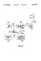
- FIG. 17shows a representative illustration of an impulse radio transmitter having three subcarrier generator/modulators in accordance with the present invention.
- FIG. 18is a representative analog embodiment showing the cross correlator followed by plural analog FM demodulation branches in accordance with the present invention.
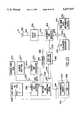
- FIG. 19shows a digital embodiment in accordance with the present invention.
- FIG. 20is a plot showing delay time (in picoseconds) versus a binary (i.e., numeric) input value for a conventional binary-to-time delay generator in accordance with the present invention.
- FIG. 21is a high-level block diagram showing the above linearization scheme in accordance with the present invention.
- FIG. 22is a functional diagram illustrating linearization ROM 2110 in accordance with the present invention.
- FIG. 23shows a combined PN code and linearization E-PROM in accordance with the present invention.
- FIG. 24illustrates a further embodiment of the impulse radio receiver in accordance with the present invention.
- FIGS. 25A, 25B, 25C, 25D, 25E, 25F, 25G and 25Hillustrate time(t) versus voltage plots of various signals numbered in FIG. 24 in accordance with the present invention.
- FIGS. 25I, 25J, 25K and 25Lillustrate frequency versus amplitude plots corresponding to FIGS. 25E-25H in accordance with the present invention.
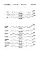
- FIGS. 26A, 26B, 26C, 27A, 27B, 27C, 27D, 27E, 27F and 27Gshow exemplary waveforms for pseudo Manchester encoding and decoding, respectively, in accordance with the present invention.
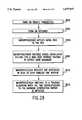
- FIG. 28is a high-level block diagram of operations performed by the impulse radio receiver to acquire lock in accordance with the present invention.
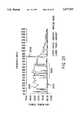
- FIG. 30shows a curve that illustrates a specific example of the projected trade-off between free space range and bit rate in accordance with the present invention.
- FIG. 31shows that it is easy to resolve multipath impulse signals in the time domain in accordance with the present invention.
- Subcarrier Channelse.g., voice, digital data and control information
- the impulse radio communication systemis an ultrawide-band time domain system that operates in the time domain and uses one or more subcarriers to provide channelization, smoothing and fidelity.
- a single impulse radio transmission(e.g., a link) can therefore communicate many independent channels simultaneously by employing different subcarriers for each channel.
- the impulse radio transmitteruses modulated subcarrier(s) for time positioning a periodic timing signal or acoded timing signal.
- the coded timing signalcan be mixed (or summed) with the modulated subcarrier(s) and the resultant signal usedto time modulate the periodic timing signal.
- Direct digital modulation of datais another form of subcarrier modulation for impulse radio signals. Direct digital modulation can be used alone to time modulate the periodic timing signal or the direct digitally modulated periodic timing signal canbe further modulated with one or more modulated subcarrier signals.
- Impulse radio technologyis widely applicable for wireless communications applications. Because impulse radiois not a continuous wave (CW) carrier-based system, the use of a subcarrieris an elegant, counter intuitive addition to the time domain impulse radio design. Signal-to-noise is improved considerably compared to non-subcarrier impulse radio transmissions.
- CWcontinuous wave
- Impulse radiosgenerally have: short duration pulses; center frequencies typically between 50 MHz and 10 gigahertz (GHz); ultrawide bandwidths of 100+% of the center frequency; multi-mile ranges with sub-milliwatt average power levels, even with low gain antennas; extremely low power spectral densities; lower cost than other sophisticated radio designs, especially spread spectrum systems; and excellent immunity to jamming fromother systems and to multipath fading.
- center frequenciestypically between 50 MHz and 10 gigahertz (GHz); ultrawide bandwidths of 100+% of the center frequency
- multi-mile ranges with sub-milliwatt average power levels, even with low gain antennasextremely low power spectral densities
- lower cost than other sophisticated radio designs, especially spread spectrum systemsand excellent immunity to jamming fromother systems and to multipath fading.
- impulse radioshave exceptional multipath immunity, they are relatively simple and less costly to build, especially in comparison to spread spectrum radios.
- Impulse radio systemsconsume substantially less power than existing conventional radios. Additionally, impulse radio systems occupy less space than existing portable telecommunications transceivers.
- impulse radiois an optimal technology for a wide variety of applications, including personal communications systems and in-building communications systems.
- Section IIis directed to technology basics and provides the reader with anintroduction to impulse radio concepts, as well as other relevant aspects of communications theory. This section includes subsections relating to Gaussian monocycle pulses, pulse trains of gaussian monocycle pulses, modulation, coding, and qualitative and quantitative characteristics of these concepts.
- Section IIIis directed to the use of subcarriers for impulse radio communication systems. This section includes subsections relating to the theory of operation of subcarriers for the impulse radio transmitter and receiver. The description is sectioned to describe a one channel embodiment with improvement over baseband alone and a two or more subcarrier channel embodiment
- Section IVis directed to the time modulator that is used for code time delaying, subcarrier time delaying and a combination of both.
- the operation and structure of several embodiments for using the time modulator for subcarrier impulse radio communicationsare described.
- Section Vis directed to linearization of the time modulator for both the impulse radio transmitter and receiver. Linearization of the time modulator permits the impulse radio transmitter and receiver to generate time delays having the necessary accuracy for impulse radio communications.
- Section VIIis directed to a lock acquisition scheme for the impulse radio receiver to acquire and maintain lock of impulse radio signals.
- Section VIIIdescribes the performance of impulse radio communications systems in the real world with reference to data collected by the inventors based on prototype testing.
- This sectionis directed to technology basics and provides the reader with an introduction to impulse radio concepts, as well as other relevant aspects of communications theory. This sections includes subsections relating to Gaussian monocycle pulses, pulse trains of gaussian monocycle pulses, modulation, coding, and qualitative and quantitative characteristics of these concepts.
- Impulse radio transmittersemit short Gaussian monocycle pulses with a tightly controlled average pulse-to-pulse interval.
- Impulse radio transmittersuse pulse widths of between 20 and 0.1 nanoseconds (ns) and pulse-to-pulse intervals of between 2 and 5000 ns. These narrow monocycle pulses have inherently wide-band frequency characteristics.
- Impulse radio systemsuses pulse position modulation, with the actual pulse-to-pulse interval being varied on a pulse-by-pulse basis by two components: an information component and a pseudo-random code component.
- the pseudo-random codeis not necessary for energy spreading (because the impulses themselves are inherently wide-band), but rather for channelization, energy smoothing in the frequency domain, and jamming resistance.
- the impulse radio receiveris a homodyne receiver with a cross correlator front end.
- the front endcoherently converts the electromagnetic pulse train to a baseband signal in one stage.
- the impulse radio receiverintegrates multiple pulses to recover each bit of the transmitted information.
- Gaussian monocyclewhich are also referred to herein as Gaussian monocycle pulses.
- a Gaussian monocycleis the first derivativeof the Gaussian function.
- FIGS. 1A and 1Bshow a 2 GHz center frequency (i.e., a 0.5 ns pulse width) monocycle pulse in the time and frequency domains (see 102 and 104, respectively).
- a 2 GHz center frequencyi.e., a 0.5 ns pulse width
- monocycleswhich are sometimes called impulses, are not gated sine waves.
- the Gaussian monocycle waveformis naturally a wide bandwidth signal, with the center frequency and the bandwidth completely dependent upon the pulse's width.
- the Gaussian monocycleis described mathematically by: ##EQU1##
- Ais the peak amplitude of the pulse
- tis time
- ⁇ (tau)is a time decay constant
- the Gaussian monocycle envelopeis: ##EQU2##
- the center frequencyis then: ##EQU3##Relative to c, the 3 dB down points (power) are:
- the bandwidthis approximately 160% of the center frequency. Because ⁇ (tau) also defines the pulse width, then the pulse width specifies both the center frequency and bandwidth.
- the center frequencyof a monocycle pulseis approximately the reciprocal of its length, and itsbandwidth is approximately equal to 1.6 times the center frequency.
- Impulse radio systemsuse pulse trains, not single pulses, for communications. As described in detail below in section III, the impulse radio transmitter produces and outputs a train of pulses for each bit of information.
- FIGS. 2A and 2Bare illustrations of a 1 mpps system with (uncoded, unmodulated) 1 ns pulses in the time and frequency domains (see 102 and 104 of FIG. 1, respectively).
- this highly regular pulse trainproduces energy spikes (comb lines 204) at one megahertz intervals; thus, the already low power is spread among the comb lines 204.
- This pulse traincarries no information and, because of the regularity of the energy spikes, might interfere with conventional radio systems at short ranges.
- impulse radio systemshave very low duty cycles so the average power time domain is significantly lower than its peak power in the time domain.
- the impulse transmitteroperates 0.1% of the time (i.e., 1 ns per microsecond ( ⁇ s)).
- Additional processingis needed to modulate the pulse train so that the impulse radio system can actually communicate information.
- the additional processingalso smooths the energy distribution in the frequency domain so that impulse radio transmissions (e.g., signals) interfere minimally with conventional radio systems.
- Amplitude and frequency/phase modulationare unsuitable for this particularform of impulse communications; the only suitable choice is pulse position modulation, which allows the use of a matched filter (i.e., cross correlator) in the receiver. As illustrated in FIG. 3, a modulating signalchanges the pulse repetition interval (PRI) in proportion to the modulation.
- PRIpulse repetition interval
- the first levelmight shift the generation of the pulse forward in time from the nominal by ⁇ picoseconds (ps); the second level might not shift the pulse position in time from the nominal at all; and the third level might delay the pulse by ⁇ ps.
- pspicoseconds
- Analogmodulationwould allow continuous deviations between PRI- ⁇ and PRI+ ⁇ .
- pulse position modulationdistributes the energy over more frequencies.
- the modulation dither (d)were 100 ps
- the PRIis 1,000,000 Hertz (Hz) and theadditional frequency components are: 999,800.04 Hz, 999,900.01 Hz, 1,000,100.01 Hz, and 1,000,200.04 Hz.
- Ditheris an impulse radio communications term for moving the position of a pulse in time.
- Transmitted energyis now distributed among more spikes (comb lines) in the frequency domain. If the total transmitted energy remains constant, the energy in each frequency spike decreases as the number of possible pulse positions increases, thus, in the frequency domain, the energy is more smoothly distributed.
- the amount of time position modulation required for one-hundred percent modulationis calculated by the inverse of f c /4 (where f c is the center frequency). For a monocycle with a center frequency of 1.3 GHz, for example, this corresponds to ⁇ 157 (ps) of time position modulation. The spectrum-smoothing effects at this level of time dither is negligible.
- FIG. 4is a plot illustrating the impact of pseudo-random dither on energy distribution in the frequency domain.
- FIG. 4when compared to FIG. 2B, shows the impact of using a 256 position PN code relative to an uncoded signal.
- PN ditheringalso provides for channelization (channelization is a procedure employed to divide a communications path into a number of channels). In an uncoded system, differentiating between separate transmitters would be very hard. PN codes create channels, if the codes themselves are relatively orthogonal (i.e., there is low correlation and/or interference between the codes being used).
- an impulse radiodoes not depend on receiving every pulse.
- the impulse radio receiverperforms a correlating, synchronous receiving function (at the RFlevel) that uses a statistical sampling of many pulses to recover the transmitted information.
- Impulse radio receiverstypically integrate 200 or more pulses to yield thedemodulated output.
- the optimal number of pulses over which the receiver integratesis dependent on a number of variables, including pulse rate, bit rate, jamming levels, and range.
- the PN codingalso makes impulse radio highly resistant to jamming from all radio communications systems, including other impulse radio transmitters. This is critical as any other signals within the band occupied by an impulse signal act as a jammer to the impulse radio. Since there are no unallocated 1+ GHz bands available for impulse systems, they must share spectrum with other conventional and impulse radios without being adversely affected.
- the PN codehelps impulse systems discriminate between the intended impulse transmission and transmissions from others.
- FIGS. 5A-5Cillustrate illustrates the result of a narrowband sinusoidal jamming (interference) signal 502 overlaying an impulse radio signal 504.
- the input to the cross correlatorwould include that narrowband signal 502, as well as the received ultrawide-bandimpulse radio signal 504.
- the cross correlatorwould sample the jamming signal 502 with such regularity that the jamming signals could cause significant interference to the impulse radio receiver.
- the transmitted impulse signalis encoded with thePN code dither (and the impulse radio receiver is synchronized with that identical PN code dither) it samples the jamming signals randomly. According to the present invention, Integrating over many pulses negates the impact of jamming.
- the pseudo-randomization in time of the receive processcreates a stream of randomly distributed values with a mean of zero (for jamming signals). All that is necessary to eliminate the impact of jammers is to sample over enough pulses (i.e., integrate over a sufficiently large number of pulses) to drive the impact of the jamming signals to zero.
- Impulse radiois jam resistant because of its large processing gain.
- processing gainwhich quantifies the decrease in channel interference when wide-band communications are used, is the ratio of the bandwidth of the channel to the bandwidth of the information signal.
- a direct sequence spread spectrum system with a 10 kHz information bandwidth and a 16 MHz channel bandwidthyields a processing gain of 1600 or 32 dB.
- far greater processing gainsare achieved with impulse radio systems where forthe same 10 kHz information bandwidth and a 2 GHz channel bandwidth the processing gain is 200,000 or 53 dB.
- the duty cycle(e.g., of 0.5%) yields a process gain of 28.3 dB.
- the process gainis generally the ratio of the bandwidth of a received signal to the bandwidth of the received information signal.
- the effective oversampling from integrating over multiple pulses to recover the information(e.g., integrating over 200 pulses) yields a process gain of 28.3 dB.
- a 2 GHz divided by a 10 mpps link transmitting 50 kilobits per second (kbps)would have a process gain of 49 dB, (i.e., 0.5 ns pulse width divided by a 100 ns pulse repetition interval would have a 0.5% dutycycle, and 10 mpps divided by a 50,000 bps would have 200 pulses per bit.)
- FIGS. 6A and 6Bshow the "cross correlator transfer function" 602. This represents the output value of an impulse radio receiver cross correlator for any given received pulse. As illustrated at 604, the cross correlator's output is 0 volts when pulses arrive outside of a cross correlation window 606. As a received pulse 608 slides through the window,the cross correlator output varies.
- the cross correlator's outputhas a swing of between ⁇ 1 volt (as a function of the transmitter's modulation).
- Other in-band transmissionwould cause a variance to the cross correlator's output value.
- This varianceis a randomvariable and can be modelled as a Gaussian white noise signal with a mean value of 0. As the number of interferers increases the variance increases linearly. By integrating over a large number of pulses, the receiver develops an estimate of the transmitted signal's modulation value.
- Nnumber of interferers
- ⁇is the variance of all the interferers to a single cross correlation
- Zis the number of pulses over which the receiver integrates to recover the modulation.
- Multipath fadingthe bane of sinusoidal systems, is much less of a problem(i.e., orders of magnitude less) for impulse systems than for conventional radio systems.
- Rayleigh fadingso noticeable in cellular communications, is a continuous wave phenomenon, not an impulse communications phenomenon.
- the path length traveled by the scatteredpulsemust be less than the pulse's width times the speed of light, and/or successively emitted pulses at the transmitter (in the sequence) arrive atthe receiver at the same time.
- Pulses traveling between these intervalsdo not cause self-interference (inFIGS. 7A and 7B, this is illustrated by the pulse traveling Path 2). While pulses traveling grazing paths, as illustrated in FIGS. 7A and 7B by the narrowest ellipsoid, create impulse radio multipath effects.
- the multipath pulsetravels one half width of a pulse width further, it increases the power level of the received signal (the phase of the multipath pulse will be inverted by the reflecting surface). If the pulse travels less than one half a pulse widthfurther it will create destructive interference, as shown at 804. For a 1 ns pulse, for example, destructive interference will occur if the multipath pulse travels between 0 and 15 cm (0 and 6 inches).
- This sectionis directed to the use of subcarriers for impulse radio communication systems.
- This sectionincludes subsections relating to the theory of operation of subcarriers for the impulse radio transmitter and receiver. The description is sectioned to describe a one channel embodiment with improvement over baseband alone and a two or more subcarrier channel embodiment.
- impulse radiohas been developed to include one or more subcarriers for added channelization, smoothing and fidelity.
- the following ultrawide-band time domain impulse radio communication architecturesoperate according to the general impulse radiotheories discussed above in section II. The following three specific embodiments will be described: a one channel system, a two channel system and a three or more channel system.
- the three impulse radio receiver embodiments set forth beloware used by way of example, not limitation, to describe the present invention and enable those skilled in the relevant arts to make and use the invention. These arts include at least the fields of communications, discrete analog,digital and integrated circuit design and implementation, digital signal processing and PN code theory. The implementation of various elements and blocks will become evident to those skilled in the pertinent art.
- This sectiondescribes an impulse radio communications architecture using one subcarrier channel that has improved performance over baseband alone.
- the radio frequency (RF) embodiments of the present inventionare the mostcommon.
- Typical RF impulse radio system applicationsinclude cellular telephones, wireless telephones, wireless PBXs/Local area networks, and the like.
- Propagationwhich is defined as the process by which a signal proceeds from a transmitter to a receiver, of RF impulse radio signals is typicallythrough air or space from a transmit antenna to a receive antenna. This is considered wireless RF impulse radio.
- the preferred antennas for impulse radioare fully described in U.S. Pat. No. 5,363,108.
- the present inventionis also suitable for transmission through coaxial cable.
- the transmit and receive antennasare eliminated.
- FIG. 9A representative block diagram of an impulse radio electrical system using one subcarrier channel is shown in FIG. 9.
- a transmitter 901 and a receiver 903 employing a single subcarrier ultrawide-band impulse radio channelare depicted.
- the transmitter 901 and the receiver 903are separated by a propagation medium 905, such as air, space, or other mediumcable of propagating ultrawide-band signals.
- Transmitted impulse radio signals 907propagate through the propagation medium 905 from the transmitter 901 to the receiver 903.
- a preferred embodiment of an impulse radio transmitter 901 of an impulse radio communication system having one subcarrier channelwill now be described with reference to FIG. 10.
- the transmitter 901comprises a time base 1002 that generates a periodic timing signal 1004.
- the time base 1002comprises a voltage controlled oscillator, or the like, having a high timing accuracy on the order of picoseconds.
- the voltage control to adjust the VCO center frequencyis setat calibration the desired center frequency used to define the transmitter's non-divided pulse repetition rate.
- the periodic timing signal 1004is supplied to a code source 1006 and to a code time modulator1008.
- the code source 1006comprises a storage device such as a random access memory (RAM), read only memory (ROM), or the like, for storing orthogonal PN codes and for outputting the PN codes as a code signal 1010. Alternatively, maximum length shift registers can be used to generate the PN codes.
- Code source 1006monitors the periodic timing signal 1004 to permit the code signal 1010 to be synchronized to the code time modulator 1008.
- the code time modulator 1008uses the code signal 1010 to modulate the periodic timing signal 1004 for channelization and smoothing of a final emitted signal 1012. The output of the code time modulator 1008 is called coded timing signal 1014.
- the coded timing signal 1014is supplied to a subcarrier time modulator 1016 for information modulation thereof.
- the information modulationwas done by using the information itself as the modulating source.
- an information source 1018supplies an information signal 1020 to a subcarrier generator and modulator 1022.
- the information signal 1020can be any type of intelligence, including digital bits representing voice, data, imagery, orthe like, analog signals, or complex signals.
- Both the coded timing signal 1014 and the subcarrier time modulator 1016can be implemented using voltage, current or digital sources as modulation inputs, as would be apparent to a person skilled in the relevant art.
- a subcarrieris "a carrier, modulated with informationseparate from carrier modulation, which in turn modulates a carrier.”
- the subcarrier generator and modulator 1022 of the present inventiongeneratesa modulated subcarrier signal 1024 which is modulated by the information signal 1020, and supplies the modulated subcarrier signal 1024 to the subcarrier time modulator 1016.
- the modulated subcarrier signal 1024is used by the subcarrier time modulator 1016 to modulate the carrier, which in this case is the coded timing signal 1014. Modulation of the coded timing signal 1014 by the subcarrier time modulator 1016 generates amodulated, coded timing signal 1026 that is sent to an output stage 1028.
- the output stage 1028uses the modulated, coded timing signal 1026 as a trigger to generate electrical monocycle pulses.
- the electrical monocycle pulsesare sent to a transmit antenna 1030 via a transmission line 1032 coupled thereto.
- the electrical monocycle pulsesare converted into propagating electromagnetic pulses by the transmit antenna 1030.
- the electromagnetic pulsesare called the emitted signal 1012, and propagate to an impulse radio receiver (not shown) through a propagation medium 905, such as air in a radio frequency embodiment.
- the emitted signal(s) 1012is wide-band or ultrawide-band signals.
- the emitted signal(s) 1012can be spectrally modified by filtering of the monocycle pulses. This bandpass filtering will cause each monocycle pulse to have more zero crossings in the time domain. In this case, the impulse radio receiver must use a similar waveform in the cross correlator to be efficient.
- the addition of the subcarrier generation and modulation "stage" 1022 to the impulse radio transmitter 901has many benefits.
- the subcarrier modulated by the information signalprovides additional channelization andsmoothing to the system permitting the addition of many new, distinct impulse radio channels.
- the addition of subcarriersalso provides added fidelity in the form of more bandwidth and better signal-to-noise to the information signal 1020, compared to baseband modulation alone.
- the use of a subcarrier for impulse radiosalso improves harmonic distortion due to a non-linear modulation transfer function, compared to baseband modulation.
- the nonlinear modulation transfer functionis described below in connection with the cross correlation process performedby the impulse radio receiver.
- impulse radiois not a CW carrier-based system
- the use of a subcarrieris an elegant, counter intuitive addition to the time domain impulse radio design.
- Signal-to-noiseis improved by 5-20 dB (depending onsignal-to-noise of the narrow pulse modulated carrier) compared to non-subcarrier impulse radio transmissions.
- the subcarrier generation and modulator 1022uses a subcarrier to pulse position modulate the coded timing signal 1014.
- the modulated subcarrier signal 1024is used by the subcarrier time modulator 1016 to time shift the position of the pulses of the coded timing signal 1014.
- the signal that triggers the output stagein this case the modulated, coded timing signal 1026
- the modulated, coded timing signal 1026is a train of pulse position modulated pulses.
- Subcarriers of different frequencies or waveformscan be used to add channelization of impulse radio signals.
- an impulse radio linkcan communicate many independent channels simultaneously by employing different subcarriers for each channel.
- a first pair of userscommunicate with impulse radios having the subcarrier generator/modulators 1022 generating one sine wave subcarrier of a first discrete frequency.
- a second pair of userscommunicate with separate impulse radios having the subcarrier generator/modulator 1022 generating one sine wave subcarrier of a second discrete frequency, separate from the first frequency.
- Each user paircan have isolated communications from the other by configuring the impulse radio receivers of the two pairs (as discussed below) to reproduce only the information conveyed by the appropriate subcarrier frequency.
- many additional impulse radio channelsare availableby using the impulse radio subcarrier technique.
- the two pairs of impulse radio userscould have isolated communications if each pair used different PN codes and the same subcarriers.
- channelizationcan be achieved by having sets of radios operate at different pulse repetition rates, independent of PN codes and/or subcarriers.
- a result of the novel subcarrier stageis enhanced fidelity of the information channel. This benefit is attributed to the fact that the subcarrier inherently renders the information more impervious to noise.
- a template signal having a waveform designed to match the received monocycle pulsesis generated at the impulse radio receiver.
- the template signalis positioned in time according to the known PN code of the transmitter and is then cross correlated with the received impulse radio signal.
- the cross correlation outputis integrated to recover the impulse radio signal out of the noise. Once retrieved in this manner, the signal is demodulated to remove the subcarrier and yield the information signal.
- FIG. 11Another embodiment of the impulse radio transmitter according to the present invention is shown in FIG. 11.
- the positions of code time modulator 1008 and the subcarrier time modulator 1016are reversed.
- the information source 1018outputs the information signal 1020 to the subcarrier generator and modulator 1022.
- the subcarrier generator and modulator 1022outputs the modulated subcarrier signal 1024 to the subcarrier time modulator 1016.
- the subcarrier time modulator 1016uses the modulated subcarrier signal 1024 to lime position modulate the periodic timing signal 1004 to generate a modulated timing signal 1140. Any of the subcarrier modulation techniques described above in connection with FIG. 10 can be used.
- the code source 1006receives the periodic timing signal 1004 for synchronization and outputs the code signal 1010 to the code time modulator 1008.
- the code time modulator 1008uses the code signal 1010 to further time-position modulate the modulated timing signal 1140 to output a modulated, coded timing signal 1142.
- the modulated, coded timing signal 1142 shownin FIG. 11is provided to the output stage 1028.
- the impulse radio transmitterthen outputs an emitted signal 1012.
- FIG. 11is exemplary of the many modifications that can be made to the impulse radio transmitter to provide the necessarycoding and subcarrier modulation of the signals to be transmitted via the impulse radio transmitter.
- the above embodiments described in connection with FIGS. 10 and 11have been provided by way of example, not limitation.Similar arrangements of the blocks in FIGS. 10 and 11 of the impulse radio transmitter would be apparent to a person skilled in the relevant art based on the above disclosure without departing from the scope of the invention.
- FIG. 12Another transmitter embodiment is shown in FIG. 12.
- a summer 1202or the like, is used to sum the code signal 1010 and an information modulated subcarrier signal 1204.
- the summer 1202outputs a code modulated subcarrier signal 1206 to a code and timing modulator 1208.
- the code and time modulator 1208performs the functions of the code time modulator and the subcarrier rime modulator 1016 of FIG. 10.
- the code and timing modulator 1208uses the code modulated subcarrier signal 1206 to modulate the periodic timing signal 1004 and thus produce the modulated, coded timing signal 1026.
- the remaining elements of the receiver of FIG. 12operate as discussed in connection with FIG. 10. Any of the subcarrier modulation techniques described above in connection with FIG. 10 can be used.
- modulationcan be done using the information signal 1020 to directly modulate the code signal 1010.
- Thisisillustrated in FIG. 13.
- Summer 1202is configured to modulate (sum) the code signal 1010 with the information signal 1020 to thereby generate a modulation signal 1302.
- a code and timing modulator 1208uses the modulation signal 1302 to modulate the periodic timing signal 1004 and produce the modulated, coded timing signal 1026.
- the remaining elements ofthe receiver in FIG. 13operate as discussed in connection with FIG. 10.
- a subcarrier not modulated with informationcan also be used to modulate the coded timing signal, or the coded timing signal itself can be transmitted without any modulation. These two latter embodiments can be used to communicate the mere presence of an impulse radio like a beacon ora transponder. Different impulse radio units can be assigned different PN codes and different subcarriers to realize many operational applications.
- An impulse radio receiver 903 for a the single channel subcarrier impulse radio communication systemis now described with reference to FIG. 14.
- An impulse radio receiver (hereafter called the receiver) 1400comprises a receive antenna 1402 for receiving a propagated impulse radio signal 1404.
- a received signal 1406is input to a cross correlator 1408 via a receiver transmission line 1410, coupled to the receive antenna 1402.
- the receiver 1400also comprises a decode source 1410 and an adjustable time base 1414.
- the decode source 1410generates a decode control signal 1412 corresponding to the PN code used by the associated impulse radio transmitter (not shown) that transmitted the propagated signal 1404.
- the adjustable time base 1414generates a periodic timing signal 1416 that comprises a train of template signal pulses having waveforms substantiallyequivalent to each pulse of the received signal 1406. Each pulse of the received signal 1406 resembles the derivative of a Gaussian monocycle pulse.
- FIG. 15shows a representative plot of a pulse 1502 corresponding to the received signal 1406 in connection with the receiver 1400.
- the pulse 1502corresponds to an emitted signal (monocycle pulse) having a waveform like pulse 302 of FIG. 3.
- the receive antennahas an inherent characteristic that causes the resulting electrical waveform at its output to have the shape of pulse 1502. If the impulse radio antenna is inverted, pulse 1502 will be voltage inverted.
- FIGS. 16A-16Cillustrate the cross correlation process.
- FIGS. 16A-16Cshow the waveform of a template signal pulse 1602 and a waveform of a received (impulse radio pulse) signal 1406 at time increments of ⁇ t.
- a curve 1604is not a continuous waveform, but represents resulting correlation voltages at each ⁇ t time alignment as the received signal 1406 slides by the template signal pulse 1602 out of lock. (Note that each ⁇ t of the received signal 1406 is voltage inverted when compared to the pulse 1502.)
- the time positioning of the template signal pulse used tocorrelate with the received signal 1406is established by a decode timing modulator 1418.
- the effect of using the cross correlation function for the modulation transfer functionis to cause the output of the receiver to be a non-linear function of the amplitude of the input. For baseband modulation, this is undesirable. However, for subcarriers, such as FM, PSK, FSK and manchester, the harmonics can easily be filtered thereby eliminating any distortion. Such filtering can not remove harmonics when baseband modulation is used, because the harmonics stay at baseband, and thus the signal is irrecoverable.
- the decode control signal 1412 and periodic timing signal 1416are received by the decode timing modulator 1418.
- the decode timing modulator 1418uses the decode control signal 1412 to position in time the periodic timing signal 1416 to generate a decode signal 1420.
- the decode signal 1420is thus matched in time to the known PN code of the transmitter so that the received signal 1406 can be detected in the cross correlator 1408.
- the detection process performed by the cross correlator 1408comprises a cross correlation operation of the received signal 1406 with the decode signal 1420. Integration over time of the cross correlation generates a baseband signal 1422. As discussed above in section II.A, integration overtime of the cross correlated signal pulls the impulse radio signals out of the noise.
- the baseband signal 1422is demodulated by a subcarrier demodulator 1424 to remove the subcarrier and yield a demodulated information signal 1426.
- the demodulated information signal 1426is substantially identical to the information signal of the transmitter (see 1018 of FIG. 10).
- the baseband signal 1422is also input to a lowpass filter 1428.
- a control loop 1429 comprising the lowpass filter 1428is used to generate an error signal 1430 to provide minor phase adjustments to the adjustable time base1414 to time position the periodic timing signal 1416 in relation to the position of the received signal, 1406.
- the subcarrier embodimentsprovide less signal compression, and lower signal distortion by reducing baseband noise for high reliability voice, data and/or imagery communications.
- the linearity requirements for the modulation using the cross correlatorare greatly relaxed by using the subcarrier technique of the present invention. Modulation transfer characteristics have to be extremely linear in order to successfully transfer low distortion speech or music. This is very difficult to achievein a non-subcarrier baseband impulse system.
- phase locked loop (PLL) frequency demodulatorIn an FM subcarrier embodiment, a phase locked loop (PLL) frequency demodulator is used. The characteristics of the phase-locked loop determine the bandwidth capture and other basic aspects of the received signal. An optional bandpass filter can be used in series before the phase-locked loop to narrow the spectrum of demodulation performed by the phase-locked loop.
- PLLphase locked loop
- Subcarrier Channelse.g., voice, digital data and control information
- a major advantage of the present subcarrier impulse radiois that multiple subcarriers can be packed on the same coded timing signal for simultaneoustransmission.
- An example of three subcarriers on one impulse radio ultrawide-band transmissionis illustrated for both analog and digital implementations in FIGS. 17-19.
- FIG. 17shows a representative illustration of an impulse radio transmitterhaving three subcarrier generator/modulators (SC GEN/MOD) 1702, 1704 and 1706, each having a different subcarrier frequency.
- SC GEN/MODsubcarrier generator/modulators
- the basic architectureof the transmitteris based on the embodiment of FIG. 10.
- a main subcarrier generator/modulator 1720(shown as a dashed box) is analogous to subcarrier generator/modulator 1022.
- this examplecan be modified to operate with any of the above disclosed transmitters and their equivalents.
- a voice information source (VIS) 1708is fed to a subcarrier generator/modulator (abbreviated SC GEN/MOD in FIG. 17) 1702 via a line 1722 for modulation of a first subcarrier signal (not shown).
- the first subcarrier signalis internally generated by subcarrier generator/modulator 1702, or is externally generated and supplied as an input to subcarrier generator/modulator 1720.
- a digital data source (DDS) 1710such as a modem output or facsimile transmission, is fed to a second subcarrier generator/modulator (abbreviated SC GEN/MOD in FIG. 17) 1704, via a line (or bus) 1724, for modulation of second subcarrier signals.
- a digital control information source (CIS) 1712is fed to a third subcarrier generator/modulator (abbreviated SC GEN/MOD in FIG. 17) 1706, via a line (or bus) 1726, for modulation of a third subcarrier signal.
- the second andthird subcarriers signalsare generated by subcarrier generator/modulators 1704 and 1706, respectively, or they are externally supplied as inputs to subcarrier generator/modulator 1720.
- the digital CIS 1712provides control information to an impulse radio receiver.
- digital control informationcan comprise routing information, scheduling information, ring signals, or the like.
- Virtually any type of control signals, or for that matter, intelligence,can be used to modulate a subcarrier signal.
- Three modulated subcarrier signalsare output by the three subcarrier generators/modulators 1702, 1704 and 1706, via lines 1728, 1730 and 1732, and are summed at a summer 1714.
- a resultant signal 1716is sent to the subcarrier time modulator 1016, where it is used to modulate the coded timing signal 1014 to generate modulated, coded timing signal 1026.
- the modulated, coded timing signal 1026 output by the subcarrier time modulator 1016is fed to the output stage 1028 and transmitted as an emitted signal 1012 as described above.
- FIGS. 18 and 19Two representative plural subcarrier channel impulse radio receivers are shown in FIGS. 18 and 19. Each receiver has components for demodulating the three subcarrier channels transmitted by the transmitter of FIG. 17, for example.
- the basic architecture of the receivers in FIGS. 18 and 19isbased on the embodiment of FIG. 14, or its equivalents.
- FIG. 18is a representative analog embodiment showing the cross correlator 1408 followed by plural analog FM demodulation branches.
- the cross correlated baseband signal 1422is generated from the received signal 1406, as discussed in connection with FIG. 14 (using the elements of the control loop which are not illustrated in FIGS. 18 and 19).
- Each branchdemodulates one subcarrier using a bandpass filter 1802 (e.g., an L-C or switched capacitor filter) and a phase-locked loop block 1804.
- a bandpass filter 1802e.g., an L-C or switched capacitor filter
- the cross correlated baseband signal 1422is converted into a digital signal using an analog-to-digital converter (A/DC) 1902.
- A/DCanalog-to-digital converter
- DSPdigital signal processor
- the three separate subcarriers encoded in signal 1903are digitally demodulated.
- the digitally demodulated informationcan be converted back to analog using digital-to-analog converter (D/AC) 1906.
- D/ACdigital-to-analog converter
- the voice signalis converted back to its analog counterpart using digital-to-analog converter 1906 and made available at OUTPUT 1.
- the digital data signalis output or otherwisemade available directly from the digital signal processor at OUTPUT 2.
- the control signalis output or otherwise made available at OUTPUT 3 directly from the digital signal processor or after digital-to-analog conversion by digital-to-analog converter 1906.
- the addition of plural subcarriersdoes not affect the wide band characteristics of the impulse radio signals.
- This sectionis directed to the time modulator that is used for code time delaying, subcarrier time delaying and a combination of both.
- the operation and structure of several embodiments for using the time modulator for subcarrier impulse radio communicationsare described.
- the impulse radio transmitterincludes code time modulators (e.g., 1008) and subcarrier time modulators (e.g., 1016), as well as code and timing modulators (e.g., 1208).
- code time modulatorse.g., 1008
- subcarrier time modulatorse.g., 1016
- code and timing modulatorse.g., 1208
- Each of these modulatorsfunctions to time delay a signal (e.g., the periodic timing signal 1004) according to information conveyed by a trigger signal (e.g., code signal 1010 or modulated subcarrier signal 1024.)
- a trigger signale.g., code signal 1010 or modulated subcarrier signal 1024.
- each modulatore.g., 1008, 1016 or 1208
- Delay generators having numericinput signalsare called binary-to-time delay generators.
- Binary-to-time delay generatorscan be implemented using currently available commercial ICs.
- a preferred delay generator having a numeric inputis a model MC100E196 ECL (emitter coupled logic) device manufacturedby Motorola, of Schaumburg, Ill.
- ECLemitter coupled logic
- such conventional binary-to-time delay generatorsdo not provide accurate time delays to permit accurate recovery of impulse radio signals at the impulse radio receiver.
- time delays on the order of 157 ps (picoseconds)which is a typical pulse duration of a monocycle pulse, cannot accurately be produced using conventional binary-to-time delay generators.
- This sectionis directed to linearization of the time modulator for both the impulse radio transmitter and receiver.
- Linearization of the time modulatorpermits the impulse radio transmitter and receiver to generate time delays having the necessary accuracy for impulse radio communications.
- the impulse radio transmittercomprises alinearization look-up read only memory (ROM) (not illustrated), in conjunction with conventional binary-to-time delay generators to compensate for any non-linearity. This permits the impulse radio transmitter to generate time delays having accuracy well below the 157 ps requirement.
- ROMread only memory
- FIG. 20is a plot showing delay time (in picoseconds) versus a binary (i.e., numeric) input value for a conventional binary-to-time delay generator.
- a curve 2002shows an example of the actual time delay output characteristics of a conventional binary-to-time delay generator.
- the desired output of a binary-to-time delay generator for use with the present inventionis shown at a curve 2004.
- a point 2010 on curve 2002represents the actual output of a conventional binary-to-time delay generator.
- a binary input value of 10would typically be input to produce a 157 ps time delay at the output of the conventional binary-to-time delaygenerator.
- a conventional binary-to-time delay generatormay produce an actual output value of only approximately 15 ps, rather than the desired 157 ps, as shown at a point 2006.
- a numericinput value of 18would need to be input to produce the desired delay of 157 ps, as shown at a point 2010 on the curve 2002.
- linearization dataof the type shown in FIG. 20, is used to map the actual response of a conventional binary-to-time delay generator to a desired time delay.
- This linearizationdata, or mapis stored in a linearization read only memory (ROM).
- ROMlinearization read only memory
- pulsesare time-modulated either forward or backward in time.
- impulse radio signalsthat are intended to produce a logical value of 1 when received by the impulse radio receiver, are time positioned slightly forward by the impulse radio transmitter.
- Impulse radio signals that are intended to be received as logical 0'sare time shifted slightly back by the impulse radio transmitter.
- the cross correlator 1408 in the impulse radio receiverconverts that time position into more positive or more negative voltage increments.
- a bandpass data filteris used to maximize the signal-to-noise ratio of the data stream.
- the bandwidth of this bandpass data filteris set to approximately one-half the transmission baud rate, as would be apparent toa person skilled in the relevant art.
- a comparatorthen turns those voltages into logical equivalents of 1's and 0's. It is necessary to supply a pulse for both 1's and 0's because, in the absence of a pulse, noise at the threshold of the comparator would produce a random output.
- the larger the separation (i.e., voltage difference) between the positive and negative information samplesthe better the signal to noise ratio andthe lower the bit error rate.
- the linearization ROMmust store separate linearization information for impulse radio signals for the logic 1 and separate linearization data for impulse radio signals for the logic 0.
- impulse radio transmission logic 1's and logic 0'smust be shifted ahead and back, respectively, in time by a finite amount so that the cross correlator in the impulse radio receiver can properly distinguish logic 1's from logic 0's in the data stream.
- linearization ROMmust store one (8 bit) digital value representing a linearized numeric value, such that when output from the linearization ROM to the code time modulator 1408, the proper 157 ps time shift can be realized.
- the linearization ROMwill store one 8 bit numerical value for a forward shiftof 157 ps and a second 8 bit numerical value for a backward shift of 157 ps.
- the linearization ROMIn order to achieve forward and backward shifts of some other time shift in addition to that of 157 ps, the linearization ROM must store further 8 bit numerical values for forward and backward time shifts. Note that if the transmitter used a modulator employing a zero time shift (nominal) and two times 157 ps for the modulation values (corresponding todigital zero and one, respectively), that this would look the same to a demodulating receiver.
- FIG. 21is a high-level block diagram showing the above linearization scheme according to the present invention.
- a direct digital coded timing signal 2102is produced by the code time modulator 1008 as illustrated in the block diagram of FIG. 21.
- the time base 1002outputs the periodic timing signal 1004 to the code source 1006.
- the periodic timing signal 1004is also provided to the code time modulator 1008, which in this embodiment is a binary-to-time delay generator.
- the code source 1006comprises an address counter 2104 and two read-only memories (ROMs) 2106 and 2110.
- the periodic timing signal 1004increments the address counter 2104 that outputs a multi-bit address 2105.
- the address counter 2104outputs a 15-bit-wide address 2105 for each pulse of the periodic timing signal 1004.
- the address 2105 provided by address counter 2104is used to access a PN code ROM 2106.
- the ROM 2106stores PN (pseudo-random noise) code of a predetermined modulo.
- PNpseudo-random noise
- Each address 2105 output from the address counter 2104accesses a storage location in the ROM 2106, which in response thereto, outputs a PN code 2108 (preferably a 15-bit PN code).
- the PN codesare used to time-position modulate pulses (e.g., periodic time signal pulse or digitaldata signal pulses) ahead or back in time for channelization and spreading of the monocycle pulses of the impulse radio signal.)
- Linearization datais stored at addressable locations in a linearization ROM 2110.
- the linearization datais accessed by application of an address (e.g. a 16-bit address) to address inputs of the linearization ROM 2110.
- an addresse.g. a 16-bit address
- the 16-bit addressis formed by the concatenation of the 15-bit PN code 2108 output by ROM 2106 and a 1-bit digital data source (shown by dashed line 2107, which is analogous to 1024 of FIG. 10) provided by information source 1018, for example.
- the digital data provided by information source 1018can be used to modulate a subcarrier using the subcarrier/generator 1022, as described herein.
- the subcarrier/generator 1022would provide the 1-bit digital data signal (see solid line 2109) to the linearization ROM 2110.
- the linearization ROM 2110In response to synchronized receipt of a complete input address (16 bits in this example), the linearization ROM 2110 outputs a linearized, modulated timing signal 2112 (which is analogous to 1206 of FIG. 12 and 1302 of FIG.13).
- the linearized, modulated timing signal 2112is preferably 8-bits wideand is provided to the code time modulator (i.e., binary-to-time delay generator) 1008.
- the code time modulator 1008uses the modulated timing signal 2112 to time delay the periodic timing signal 1004 and thus output the direct digital coded timing signal 2102.
- the linearization ROM 2110stores linearization data in order to properly linearize time delays provided by the PN code ROM 2106.
- Each 15 bit pseudo-random code 2108 provided to the linearization ROM 2110represents a dither time delay used to time modulate the digital data bit 2107 that is simultaneously provided to the linearization ROM 2110.
- 2 15 (23,768) different time delayscan be used to time modulate the forward time shift of logic 1 or the backward time shift of logic 0.
- the modulation of the time delay composed by the PN noise code prior to cross correlation in the impulse radio receiverpermits recovery of the data.
- the preferred embodiment of the impulse radio receiver describing this operationis discussed below.
- FIG. 22is a functional diagram illustrating linearization ROM 2110.
- Locations 2202 and 2204 of the FIG. 22represent storage locations within the linearization ROM 2110 addressed by high-order addresses and low orderaddresses, respectively.
- each storage locationcan store 8bits of data.
- the data stored within the linearization ROM 2110is separated in two groups: the data in locations 2202 and the data in locations 2204.
- the first group of datarepresents linearization data used when digital data source 2107 is a logic 1, for example, and the linearization data stored in the second group (locations 2204) represent linearization data used when digital datasource 2107 is a logic 0.
- the logic value of the digital data source 2107 which forms the most significant bit of the ROM addressdictates whether linearization data will be output from blocks 2202 or from blocks 2204.
- the 15 bits of PN code 2108 applied to the 15 least significant address inputs of the linearization ROM 2110are used to select which specific ROMlocation within either selected set of locations 2202 or 2204 will be output by linearization ROM 2110.
- the PN codescan be mathematically combined with the linearization data and the resultant numeric information can be stored directly in a single ROM, or the like.
- This further embodimentavoids the need for two ROMs.
- the address counter 2104would simply directly input addresses to a single PN code/linearization ROM.
- each element of a PN codeis called a "chip.”
- a PN code having a length of modulo Ncomprises a total of N chips.
- a single ROMcan be used to store a linearized version of the desired delay for each code chip.
- FIG. 23A still further embodiment of the impulse radio transmitter is shown in theblock diagram, FIG. 23.
- a combined PN code and linearization E-PROM 2302is used to generate an 8-bit coded information signal 2304, which represents a time delay to be generated by the code time modulator 1008.
- Use of the PN codecan be switched on and off using a code switch 2306.
- the codemay be eliminated for various reasons, such as a separate operational mode that permits accelerated signal acquisition and lock at the impulse radio receiver.
- the code switch 2306can be controlled by a simple switch, separate control logic, a microprocessor, or the like.
- the time base 1002is used to clock the address generator 2104, as described above in connection with FIG. 21.
- the time baseis shown as being implemented with a VCO 2308 and a programmable divider 2310. The functions performed by the VCO 2308 and the programmable divider 2310 would be apparent to a person skilled in the relevant art.
- a counter start page block 2312provides an address (preferably 15 bits) to the address generator 2104 to indicate a starting address.
- the counter stop page block 2314provides an address (also preferably 15 bits) to the counter limit comparator block 2316 to indicate a stop address.
- the counter limit comparators of block 2316comprise logic to compare the address, generated by the address generator 2104, to the stop page address provided by counter stop page 2314.
- the counter limit comparators block 2316generates a load signal 2317 and forwards the load signal 2317 to the address generator 2104 when a comparison of these addresses yields an equality.
- the address generator 2104In response to receiptof the load signal 2317, the address generator 2104 is reset and begins counting again at the 15-bit address specified by the counter start page 2312. The process of counting up from the start page address to the stop page address is repeated continuously. The repeating of these addresses permits the PN code and linearization E-PROM 2306 to modulate the digital data with a PN code modulo of a length determined by the difference between the counter start page and the counter stop page addresses.
- PN code and linearization E-PROM 2302is used to generate an 8-bit coded information signal 2304, which represents a time delay to be generated by the code time modulator 1008.
- Code time modulator1008 time positionmodulates the coded information signal 2304 using the periodic timing signal 1004.
- the code time modulator 1008outputs the direct digital coded timing signal 2102, as described above in connection with FIG. 21.
- the embodiment illustrated in FIG. 23also includes an FM subcarrier modulator 2318.
- the FM subcarrier modulator 2318generates a sinusoidal signal 2320.
- the sinusoidal signal 2320is summed with baseband audio signal 2342 provided by baseband audio source 2344 at a summer 2322.
- baseband audio sourceis an example of information source 1018.
- the summer 2322outputs a modulator signal 2324 used by the subcarrier timemodulator 1016 in a manner similar to that described above in connection with FIG. 10.
- the recovered sinusoidal signal 2320can be used as a control signal by the impulse radio receiver.
- the embodiment of the impulse radio transmitter illustrated by FIG. 23transmits three separate information conveying signals in a single impulse radio transmission. These three information conveying signals comprise the digital data 2107, the sinusoidal signal 2320 and the baseband audio signal 2342.
- block 2344 in FIG. 23can be replaced by a subcarrier generator and modulator 1022, as described above in connection with FIG. 10, or blocks 1018 and 2318 could each be replaced with one of the subcarrier generators/modulators 1702, 1704, 1706, as described above in connection with FIG. 17.
- the direct digital coded timing signal 2102can be directly input to the output stage 1028.
- Manchester codingis the only form of subcarrier modulation performed.
- Other configurationswill be apparent to a person skilled in the relevant art after reading this disclosure.
- FIG. 24A further embodiment of the impulse radio receiver is illustrated in FIG. 24.
- This embodiment of the impulse radio receiveris similar in many respects to the receiver described above in connection with FIG. 14.
- the receiver illustrated in FIG. 24comprises a cross correlator 1408, a subcarrier demodulator 1424, a low pass filter 1428, an adjustable time base 1414, a decode timing modulator/decode source 2402, a pseudo Manchester decoder 2404 and a microprocessor 2406.
- a propagation signal(1404) is received by the impulse radio receiver antenna 1402, which passes the received signal 1406 to an RF amplifier 2408.
- the RF amplifier 2408amplifies and passes the received signal to the cross correlator 1408.
- the cross correlator 1408can include a multiplier 2410, a triggered waveform generator 2412, an amplifier 2414, an integrator 2416, a sample and hold unit 2418, and a delay unit 2420.
- the multiplier 2410is a doublebalanced mixer adapted to operate in the linear mode.
- the multiplier 2410linearly multiplies the received signal with a template signal 2422 generated by the triggered waveform generator 2412.
- a product signal 2415 of the multiplier 2410is buffered by amplifier 2414 and then integrated over time by integrator 2416.
- the integratoris essentially a low-pass filter of first order, which is adapted to respond on a time scale similarto the width of the monocycle (i.e., 157 ps). Integrator 2416 outputs a signal 2417 to the sample and hold unit 2418 that holds the peak value of signal 2417.
- the delay unit 2420is for proper triggering of the sample and hold unit 2418.
- the delay unit 2420allows for delay caused by the multiplier 2410, and the amplifier 2414, and for integrator settling time.
- the delay unit 2420delays triggering approximately 10-15 ns after the peak value produced by the integrator 2416. As a result, sampling occurs before the integrated value degrades.
- the decode signal 1420is generated in a manner similar to generation of the direct digital coded time signal 2102, discussed above in connection with FIG. 21.
- the main difference for block 2402 in the impulse radio receiver, versus the impulse radio transmitter,is that a data source is not used toaccess the PN code/linearization ROM.
- Decode timing modulator/decode source 2402comprises a binary-to-time delaygenerator 2424, a PN code and linearization ROM 2426, and an address counter and limit logic block 2428. Start address and stop address signalsare provided to the address counter and limit logic block 2428 from the microprocessor 2406 via lines 2430 and 2432, respectively. Addresses are output from the address counter and limit logic block 2428 via a bus 2434. The address counter and limit logic block 2428 provides addresses to accessthe PN code and linearization ROM 2426 when triggered by the periodic timing signal 1416 provided by the adjustable time base 1414.
- a PN code(that corresponds to a known PN code used by an impulse radio transmitter)is output by the PN code and linearization ROM 2426 via a bus 2436 and is provided to the binary-to-time delay generator 2424.
- the binary-to-time delay generator 2424time modulates the periodic timing signal 1416 (received from adjustable time base 1414) to generate the decode signal 1420.
- the adjustable time base 1414comprises a programmable divider 2438 and a voltage controlled oscillator (VCO) 2440, which are used to output the periodic timing signal 1416.
- VCOvoltage controlled oscillator
- a voltage control signalis provided to the VCO 2440 from the microprocessor 2406 via a line 2442 to adjust the VCO output, as will be apparent to a person skilled in the relevant art.
- the subcarrier demodulator 1424comprises a bandpass filter 2444, a phase-locked loop 2446, and a low-pass filter 2448.
- the function performed by the phase-locked loop 2446is equivalent to that performed by similar phase-locked loops (2004) in FIG. 18.
- the bandpass filter 2444performs a similar function as the band filters 1802 in FIG. 18.
- bandpass filter 2444outputs a filtered signal 2445 to the phase-locked loop 2446.
- the phase-locked loop 2446outputs an in-phase estimate signal 2447 via a further low pass filter 2449 to the microprocessor 2406.
- the in-phase estimate signal 2447provides the microprocessor 2406 with an estimate of the amplitude of the subcarrier sothat the microprocessor 2406 can assess the quality of signal lock.
- a demodulated output signal 2450 of the phase-locked loop 2446is filtered by low-pass filter 2448, which in turn outputs demodulated information signal 1426.
- the overall functionality and operation of the subcarrier demodulator 1424 in FIG. 24is substantially the same as that described above in connectionwith FIG. 14.
- the control loop 1429has the same functionality as describedabove in connection with FIG. 14.
- Additional subcarrier modulationis achieved according to another aspect ofthe invention using pseudo Manchester coding of digital data. It is referred to as "pseudo" because conventional Manchester coding performs digital decoding. According to the present invention, however, decoding ofManchester encoded signals is performed in the analog domain.
- the pseudo-Manchester encodingshifts digital information from the baseband toa frequency equivalent to an integral submultiple of the adjustable time base, or integer multiples of the time base. This achieves a coherent shift of digital data for proper recovery in the impulse radio receiver.
- the pseudo Manchester decoder 2404comprises a bandpassfilter 2450 and an analog Manchester decoder 2452.
- the bandpass filter 2450receives the baseband signal 1422 from cross correlator 1408.
- a filtered baseband signal 2454is provided to analog Manchester decoder 2452.
- the decoding performed by the analog Manchester decoder 2452is best describedafter explanation of the actual encoding performed at the transmitter.
- FIG. 24various signals numbered in FIG. 24 are illustrated as time (t) versus voltage plots in FIGS. 25A-25H. Additional FIGS. 25I-25L are frequency versus amplitude (P or log P) plots that correspond to FIGS. 25E-25H.
- This sectionis directed to pseudo Manchester coding for modulation of digital data using impulse radio communications.
- This further subcarrier embodimentcomprises a modulation scheme in which data is synchronously exclusive-ORed (XORed) with a square wave whose frequency is at least two times the frequency of the data signal (a 2 ⁇ clock) in the manner of Manchester coding.
- XORedsynchronously exclusive-ORed
- Use of Manchester coding in a impulse radio systemis a subcarrier technique because the data is modulated to a higher frequency using the 2 ⁇ clock.
- the impulse radio receiverremoves this modulation in an analog fashion rather than digitally, as is done with true Manchester decoding.
- the voltage from the sample-and-hold (2418)is modulated by a synchronous 2 ⁇ clock, and sequentially processed by a low-pass filter followed by a comparator (not shown).
- the simplest embodimentis a low-pass filter set to cut off at a frequency above approximately half the bit rate; however, more complex filtering would be needed for use with other translation methods.
- the pseudo Manchester modulation techniqueconverts non-return-to-zero (NRZ) digital signals to return-to-zero (RZ) signals to avoid errors in the phase-locked loop of the impulse radio receiver.
- the return-to-zero encodercan be a pseudo Manchester direct digital encoder, a frequency shift keying encoder, an n-ary phase modulation encoder (e.g., quadrature phase shift keying (QPSK)) or a phase amplitude modulation encoder, or other frequency translation means as would be apparent to a person skilledin the relevant art.
- QPSKquadrature phase shift keying
- the pseudo Manchester coding schemeuses a standard implementation of Manchester coding in the impulse radio transmitter.
- the digital data streamis Manchester coded before it is usedto address the PN-code and linearization E-PROM 2302, for example (see FIG.23).
- the circuitry to implement Manchester coding of the digital data streamwould be apparent to a person skilled in the relevant art.
- FIGS. 26A-26C and 27A-27Gshow exemplary waveforms for pseudo Manchester encoding and decoding, respectively, according to the present invention.
- a sample digital data stream of logic 1's and 0'sis shown generally at a waveform 2602.
- the datais XORed with a square wave whose frequency is at least two times thefrequency of the data signal (a 2 ⁇ clock), as shown at a waveform 2604.
- the waveform 2604must be synchronous and have transitions aligned with a data bit edge.
- the XORed result of waveforms 2602 and 2604is showngenerally at a waveform 2606. This process ensures a zero-to-one or one-to-zero transition at the middle of each bit period, which eliminates problems associated with a long run of 1's or 0's.
- the impulse radio receiverperforms pseudo Manchester decoding to recover the digital data signal.
- a set of waveforms illustrating the functions performed to recover the dataare shown in a FIGS. 27A-27G.
- the filtered baseband signal 2454is fed to a first input of an analog multiplier (not shown).
- the second input of the analog multiplierreceivesa synchronous, 2 ⁇ clock signal (2704).
- the analog multiplierreverses the process performed by the impulse radio transmitter.
- a product (output)signal of the analog multiplieris shown generally at a waveform 2706.
- the product signalis low-pass filtered and compared with a predetermined comparison level, as shown generally by the waveform at 2708, thus yielding a compare data signal 2710.
- the compare data signal 2710is held at the peak of the impulse/response point of the filter (using a sample and hold unit), via the rising edge of a data strobe signal (shown generally at waveform 2712), to produce recovered data 2465, shown generally at a waveform 2714.
- the analog recovery techniquetakes advantage of the coherent link, i.e., synchronous recovery, to reduce the noise as much as theoretically possible with filtering.
- This sectionis directed to a lock acquisition scheme for the impulse radioreceiver to acquire and maintain lock of impulse radio signals.
- FIG. 28is a high level block diagram of operations performed by the impulse radio receiver to acquire lock.
- the microprocessor 2406applies bias to the VCO 2440 (as shown at a step 2806) to cause the lock loop 1429 to drift at a programmed rate faster (or slower) than the remote transmitter's transmit period, as shown at a step 2808.
- biasis applied to the VCO 2440 (as shown at a step 2806) to cause the lock loop 1429 to drift at a programmed rate faster (or slower) than the remote transmitter's transmit period, as shown at a step 2808.
- a few parts-per millionis a typical offset.
- the microprocessor 2406digitizes the voltage from the cross correlator 1408 (received via the filter 1428) looking for a non-zero average voltage, which indicates the template signal is in near alignment with the received signal, as shown at a step 2808.
- the microprocessorthenreduces the difference in rates (receive VCO vs. the transmitter VCO) to begin scanning the time around the perceived time that the energy was detected, as shown at a step 2810.
- the digitizing performed by the microprocessor 2406could bedone using separate A/D converter hardware.
- filteringcould be done by the microprocessor, discrete components or active filters, as would be apparent to a person skilled in the art.
- the microprocessorswitches to a tracking algorithm in which the correlator's average voltage is kept to zero, as shown at a step 2812.
- This trackingis analogous to the quadrature lock algorithm used in conventional CW phase locked loop designs, as would be apparent to a person skilled in the art.
- One impulse radio prototypebuilt by the inventors, has an average radiated power of 450 microwatts ( ⁇ W).
- the center frequencyis 675 MHz and smoothed by a pseudo-random code with 256 positions.
- FIG. 29shows thesignal measured at 3 meters (see plot 2902) as well as ambient signals (seeplot 2904). Measurements for this figure were not adjusted to compensate for antenna performance and a 1.3 GHz /2 mpps prototype was used with an average output power of 33 ⁇ W.
- a power spike 2906 just below 900 MHzisfrom two cellular base stations, one about 400 meters distant and another about 1.6 kilometers distant.
- Spikes 2908 between 360 MHz and 720 MHzare predominantly UHF televisions stations.
- the 720 MHz spikeis a 2.2 megawatt EIRP channel 54 station, Huntsville, Ala., approximately 7 miles distant.
- the "bumpiness" of the impulse spectral measurementsreflects the impact of frequency domain multipath. Moving the receive antenna causes the location of nulls and peaks to move. This does not impact the performance of the impulse system.
- bit ratewas lowered to 7.8 kbps and range was increased to 10 meters.
- the bit error ratewas better than 10 -6 .
- FIG. 30shows a curve 3002 that illustrates the projected trade-off between free space range and bit rate, assuming a 100 ⁇ W average power (-10 dB m ), a 10 dB i receive antenna (approximately a 90 n beam), a 2 dB i transmit antenna (omni-directional dipole-like pattern), an SNR of 19.5 dB(approximately a 10 -6 BER), and a margin of 6 dB.
- FIG. 31shows that it is easy to resolve multipath impulse signals in the time domain.
- Measurements illustrated at plot 3102were made in a laboratory in a single story office complex. The laboratorycontained many feet of steel shelving, test equipment, and metal filing cabinets. One adjacent office space is occupied by a metal fabricating company. The other is occupied by a personal computer sales offices along with that company's warehouse (using steel shelving).
- the first arriving pulse(between 3 ns and 6 ns) is of lower amplitude because it travelled through more walls than some later arriving pulses.
Landscapes
- Engineering & Computer Science (AREA)
- Computer Networks & Wireless Communication (AREA)
- Signal Processing (AREA)
- Synchronisation In Digital Transmission Systems (AREA)
- Dc Digital Transmission (AREA)
- Digital Transmission Methods That Use Modulated Carrier Waves (AREA)
- Transmitters (AREA)
- Traffic Control Systems (AREA)
Abstract
Description
ƒ.sub.lower =0.319 c; ƒ.sub.upper =1.922 c.(4)
ƒ.sub.c =2.0 GHz; Δƒ.sub.c =3.2 GHz.(5)
Claims (32)
Priority Applications (19)
| Application Number | Priority Date | Filing Date | Title |
|---|---|---|---|
| US08/309,973US5677927A (en) | 1994-09-20 | 1994-09-20 | Ultrawide-band communication system and method |
| CN95195805ACN1095254C (en) | 1994-09-20 | 1995-09-20 | Ultrawide-band communications system and method |
| EP95934546AEP0782791A4 (en) | 1994-09-20 | 1995-09-20 | An ultrawide-band communications system and method |
| AU36855/95AAU712260B2 (en) | 1994-09-20 | 1995-09-20 | An ultrawide-band communication system and method |
| JP51112696AJP3781428B2 (en) | 1994-09-20 | 1995-09-20 | Ultra-wideband communication system and method |
| HK98106675.2AHK1007472B (en) | 1994-09-20 | 1995-09-20 | An ultrawide-band communication system and method |
| CA002200475ACA2200475A1 (en) | 1994-09-20 | 1995-09-20 | An ultrawide-band communications system and method |
| KR1019970701807AKR100386538B1 (en) | 1994-09-20 | 1995-09-20 | An ultrawide-band communications system and method |
| PCT/US1995/012313WO1996009694A1 (en) | 1994-09-20 | 1995-09-20 | An ultrawide-band communications system and method |
| US08/761,602US5832035A (en) | 1994-09-20 | 1996-12-06 | Fast locking mechanism for channelized ultrawide-band communications |
| US08/949,143US5963581A (en) | 1994-09-20 | 1997-10-10 | Ultrawide-band communication system and method |
| US08/949,144US5995534A (en) | 1994-09-20 | 1997-10-10 | Ultrawide-band communication system and method |
| US08/949,145US5960031A (en) | 1994-09-20 | 1997-10-10 | Ultrawide-band communication system and method |
| US08/948,781US6031862A (en) | 1994-09-20 | 1997-10-10 | Ultrawide-band communication system and method |
| US09/037,704US6430208B1 (en) | 1994-09-20 | 1998-03-10 | Ultrawide-band communication system and method |
| US09/458,010US6549567B1 (en) | 1994-09-20 | 1999-12-10 | Full duplex ultrawide-band communication system and method |
| US10/196,121US6847675B2 (en) | 1994-09-20 | 2002-07-17 | Ultrawide-band communication system and method |
| US10/411,090US7321611B2 (en) | 1994-09-20 | 2003-04-11 | Method and transceiver for full duplex communication of ultra wideband signals |
| US10/784,747US7983320B2 (en) | 1994-09-20 | 2004-02-24 | Ultrawide-band communication system and method |
Applications Claiming Priority (1)
| Application Number | Priority Date | Filing Date | Title |
|---|---|---|---|
| US08/309,973US5677927A (en) | 1994-09-20 | 1994-09-20 | Ultrawide-band communication system and method |
Related Child Applications (6)
| Application Number | Title | Priority Date | Filing Date |
|---|---|---|---|
| US08/428,489Continuation-In-PartUS5687169A (en) | 1994-09-20 | 1995-04-27 | Full duplex ultrawide-band communication system and method |
| US48799095AContinuation-In-Part | 1994-09-20 | 1995-06-07 | |
| US08/949,144DivisionUS5995534A (en) | 1994-09-20 | 1997-10-10 | Ultrawide-band communication system and method |
| US08/948,781DivisionUS6031862A (en) | 1994-09-20 | 1997-10-10 | Ultrawide-band communication system and method |
| US08/949,145DivisionUS5960031A (en) | 1994-09-20 | 1997-10-10 | Ultrawide-band communication system and method |
| US08/949,143DivisionUS5963581A (en) | 1994-09-20 | 1997-10-10 | Ultrawide-band communication system and method |
Publications (1)
| Publication Number | Publication Date |
|---|---|
| US5677927Atrue US5677927A (en) | 1997-10-14 |
Family
ID=23200447
Family Applications (8)
| Application Number | Title | Priority Date | Filing Date |
|---|---|---|---|
| US08/309,973Expired - LifetimeUS5677927A (en) | 1994-09-20 | 1994-09-20 | Ultrawide-band communication system and method |
| US08/949,143Expired - LifetimeUS5963581A (en) | 1994-09-20 | 1997-10-10 | Ultrawide-band communication system and method |
| US08/949,144Expired - Fee RelatedUS5995534A (en) | 1994-09-20 | 1997-10-10 | Ultrawide-band communication system and method |
| US08/948,781Expired - Fee RelatedUS6031862A (en) | 1994-09-20 | 1997-10-10 | Ultrawide-band communication system and method |
| US08/949,145Expired - Fee RelatedUS5960031A (en) | 1994-09-20 | 1997-10-10 | Ultrawide-band communication system and method |
| US09/037,704Expired - Fee RelatedUS6430208B1 (en) | 1994-09-20 | 1998-03-10 | Ultrawide-band communication system and method |
| US10/196,121Expired - Fee RelatedUS6847675B2 (en) | 1994-09-20 | 2002-07-17 | Ultrawide-band communication system and method |
| US10/784,747Expired - Fee RelatedUS7983320B2 (en) | 1994-09-20 | 2004-02-24 | Ultrawide-band communication system and method |
Family Applications After (7)
| Application Number | Title | Priority Date | Filing Date |
|---|---|---|---|
| US08/949,143Expired - LifetimeUS5963581A (en) | 1994-09-20 | 1997-10-10 | Ultrawide-band communication system and method |
| US08/949,144Expired - Fee RelatedUS5995534A (en) | 1994-09-20 | 1997-10-10 | Ultrawide-band communication system and method |
| US08/948,781Expired - Fee RelatedUS6031862A (en) | 1994-09-20 | 1997-10-10 | Ultrawide-band communication system and method |
| US08/949,145Expired - Fee RelatedUS5960031A (en) | 1994-09-20 | 1997-10-10 | Ultrawide-band communication system and method |
| US09/037,704Expired - Fee RelatedUS6430208B1 (en) | 1994-09-20 | 1998-03-10 | Ultrawide-band communication system and method |
| US10/196,121Expired - Fee RelatedUS6847675B2 (en) | 1994-09-20 | 2002-07-17 | Ultrawide-band communication system and method |
| US10/784,747Expired - Fee RelatedUS7983320B2 (en) | 1994-09-20 | 2004-02-24 | Ultrawide-band communication system and method |
Country Status (8)
| Country | Link |
|---|---|
| US (8) | US5677927A (en) |
| EP (1) | EP0782791A4 (en) |
| JP (1) | JP3781428B2 (en) |
| KR (1) | KR100386538B1 (en) |
| CN (1) | CN1095254C (en) |
| AU (1) | AU712260B2 (en) |
| CA (1) | CA2200475A1 (en) |
| WO (1) | WO1996009694A1 (en) |
Cited By (341)
| Publication number | Priority date | Publication date | Assignee | Title |
|---|---|---|---|---|
| US5903614A (en)* | 1996-12-26 | 1999-05-11 | Sony Corporation | Communication method and receiving apparatus |
| US5933079A (en)* | 1995-09-01 | 1999-08-03 | Remote Data Systems, Inc. | Signal discriminator and positioning system |
| US5952956A (en)* | 1984-12-03 | 1999-09-14 | Time Domain Corporation | Time domain radio transmission system |
| US5960031A (en)* | 1994-09-20 | 1999-09-28 | Time Domain Corporation | Ultrawide-band communication system and method |
| US5973637A (en)* | 1998-01-09 | 1999-10-26 | Endress + Hauser Gmbh + Co. | Partial probe mapping |
| US5982810A (en)* | 1996-04-04 | 1999-11-09 | New Japan Radio Co., Ltd. | Signal extraction circuit and correlator utilizing the circuit |
| US6020842A (en)* | 1998-10-21 | 2000-02-01 | Raytheon Company | Electronic support measures (ESM) duty dithering scheme for improved probability of intercept at low ESM utilization |
| US6078280A (en)* | 1998-01-09 | 2000-06-20 | Endress + Hauser Gmbh + Co. | Periodic probe mapping |
| US6177903B1 (en) | 1999-06-14 | 2001-01-23 | Time Domain Corporation | System and method for intrusion detection using a time domain radar array |
| WO2001006723A1 (en)* | 1999-07-16 | 2001-01-25 | Time Domain Corporation | Baseband signal converter for a wideband impulse radio receiver |
| WO2001024393A1 (en)* | 1999-09-27 | 2001-04-05 | Richards James L | System and method for monitoring assets, objects, people and animals utilizing impulse radio |
| US6218979B1 (en) | 1999-06-14 | 2001-04-17 | Time Domain Corporation | Wide area time domain radar array |
| WO2001031929A3 (en)* | 1999-10-26 | 2001-09-20 | Time Domain Corp | Mobile communications system and method utilizing impulse radio |
| US6295019B1 (en) | 1998-05-26 | 2001-09-25 | Time Domain Corporation | System and method for distance measurement by inphase and quadrature signals in a radio system |
| US6297773B1 (en) | 1998-03-23 | 2001-10-02 | Time Domain Corporation | System and method for position determination by impulse radio |
| US6304798B1 (en) | 1999-11-29 | 2001-10-16 | Storage Technology Corporation | Automated data storage library with wireless robotic positioning system |
| US6304623B1 (en) | 1998-09-03 | 2001-10-16 | Time Domain Corporation | Precision timing generator system and method |
| US20010033576A1 (en)* | 2000-01-19 | 2001-10-25 | Richards James L. | System and method for medium wide band communications by impulse radio |
| WO2001093442A1 (en)* | 2000-05-26 | 2001-12-06 | Xtremespectrum, Inc. | Ultrawide band system and method for fast synchronization using multiple detection arms |
| WO2001093444A1 (en)* | 2000-05-26 | 2001-12-06 | Xtremespectrum, Inc. | Ultra wide band system and method for fast synchronization |
| WO2002005900A2 (en) | 2000-07-19 | 2002-01-24 | Golf-Domain.Com Llc | Method and apparatus for managing golf related information obtained in part by using impulse radio technology |
| US20020018514A1 (en)* | 2000-07-06 | 2002-02-14 | Haynes Leonard S. | Method and system for fast acquisition of pulsed signals |
| US20020021774A1 (en)* | 2000-03-27 | 2002-02-21 | Robert Callaghan | Dispatcher configurable linking of software elements |
| US6351246B1 (en) | 1999-05-03 | 2002-02-26 | Xtremespectrum, Inc. | Planar ultra wide band antenna with integrated electronics |
| US6354946B1 (en) | 2000-09-20 | 2002-03-12 | Time Domain Corporation | Impulse radio interactive wireless gaming system and method |
| WO2001093443A3 (en)* | 2000-05-26 | 2002-05-23 | Xtremespectrum Inc | A low power, high resolution timing generator for ultrawide bandwidth communication systems |
| US20020061080A1 (en)* | 2000-10-13 | 2002-05-23 | Richards James L. | Method and system for reducing potential interference in an impulse radio |
| WO2001093520A3 (en)* | 2000-05-26 | 2002-05-23 | Xtremespectrum Inc | Ultra wideband pulse formation |
| WO2002042124A2 (en) | 2000-11-21 | 2002-05-30 | Time Domain Corporation | System and method for controlling air bag deployment systems |
| WO2001095508A3 (en)* | 2000-06-07 | 2002-06-06 | Time Domain Corp | Apparatus and method for pulse position modulation in an impulse radio communications system |
| WO2001097476A3 (en)* | 2000-06-12 | 2002-06-06 | Time Domain Corp | A method for specifying non-temporal pulse characteristics |
| WO2002023218A3 (en)* | 2000-09-14 | 2002-06-13 | Time Domain Corp | System and method for detecting an intruder using impulse radio technology |
| US20020075972A1 (en)* | 2000-03-29 | 2002-06-20 | Time Domain Corporation | Apparatus, system and method for one-of-many positions modulation in an impulse radio communications system |
| US6417797B1 (en) | 1998-07-14 | 2002-07-09 | Cirrus Logic, Inc. | System for A multi-purpose portable imaging device and methods for using same |
| US20020108081A1 (en)* | 2000-10-12 | 2002-08-08 | 3Com Corporation | Performance evaluation of multicarrier channels with forward error correction and automatic retransmission request |
| US6437756B1 (en) | 2001-01-02 | 2002-08-20 | Time Domain Corporation | Single element antenna apparatus |
| US6452959B1 (en)* | 1999-05-28 | 2002-09-17 | Dot Wireless, Inc. | Method of and apparatus for generating data sequences for use in communications |
| US20020131398A1 (en)* | 2001-03-13 | 2002-09-19 | Fantasma | Maintaining a global time reference among a group of networked devices |
| US20020135815A1 (en)* | 2001-01-22 | 2002-09-26 | Time Domain Corporation | Hand-held scanner with impulse radio wireless interface |
| US6466125B1 (en)* | 1998-03-23 | 2002-10-15 | Time Domain Corporation | System and method using impulse radio technology to track and monitor people needing health care |
| US6469628B1 (en)* | 1998-03-23 | 2002-10-22 | Time Domain Corporation | System and method for using impulse radio technology in the farming field |
| US20020168003A1 (en)* | 2000-11-13 | 2002-11-14 | Richards James L. | System and method of communicating high rate pulse signals in a multipath environment |
| US6483461B1 (en) | 2000-08-24 | 2002-11-19 | Time Domain Corporation | Apparatus and method for locating objects in a three-dimensional space |
| US6489893B1 (en) | 1998-03-23 | 2002-12-03 | Time Domain Corporation | System and method for tracking and monitoring prisoners using impulse radio technology |
| US6492906B1 (en) | 1998-03-23 | 2002-12-10 | Time Domain Corporation | System and method using impulse radio technology to track and monitor people under house arrest |
| US20020196845A1 (en)* | 2001-06-13 | 2002-12-26 | Richards James L. | Method and apparatus for improving received signal quality in an impluse radio system |
| US6501393B1 (en) | 1999-09-27 | 2002-12-31 | Time Domain Corporation | System and method for using impulse radio technology to track and monitor vehicles |
| US20030002592A1 (en)* | 2001-06-28 | 2003-01-02 | Hannah Eric C. | Method and apparatus for an ultra-wideband radio utilizing MEMS filtering |
| US6504483B1 (en) | 1998-03-23 | 2003-01-07 | Time Domain Corporation | System and method for using impulse radio technology to track and monitor animals |
| US6505032B1 (en) | 2000-05-26 | 2003-01-07 | Xtremespectrum, Inc. | Carrierless ultra wideband wireless signals for conveying application data |
| WO2002031998A3 (en)* | 2000-10-10 | 2003-01-16 | Xtremespectrum Inc | Wavelet receiver with removal of dc offset |
| US6512455B2 (en) | 1999-09-27 | 2003-01-28 | Time Domain Corporation | System and method for monitoring assets, objects, people and animals utilizing impulse radio |
| US6512488B2 (en) | 2001-05-15 | 2003-01-28 | Time Domain Corporation | Apparatus for establishing signal coupling between a signal line and an antenna structure |
| US6519464B1 (en) | 2000-12-14 | 2003-02-11 | Pulse-Link, Inc. | Use of third party ultra wideband devices to establish geo-positional data |
| US20030032422A1 (en)* | 2001-08-13 | 2003-02-13 | Wynbeek John C. | Asymmetric wireless communication system using two different radio technologies |
| US6529568B1 (en) | 2000-10-13 | 2003-03-04 | Time Domain Corporation | Method and system for canceling interference in an impulse radio |
| US6539213B1 (en) | 1999-06-14 | 2003-03-25 | Time Domain Corporation | System and method for impulse radio power control |
| US6538615B1 (en) | 2000-05-19 | 2003-03-25 | Time Domain Corporation | Semi-coaxial horn antenna |
| EP1298811A1 (en)* | 2001-09-27 | 2003-04-02 | STMicroelectronics S.A. | Method and apparatus for detecting impulses from a received ultra wideband signal |
| EP1298812A1 (en)* | 2001-09-27 | 2003-04-02 | STMicroelectronics S.A. | Method and apparatus for decoding an incoming ultra wideband impulse signal, in particular for a wireless communication system |
| US6549567B1 (en) | 1994-09-20 | 2003-04-15 | Time Domain Corporation | Full duplex ultrawide-band communication system and method |
| US20030072273A1 (en)* | 2001-09-07 | 2003-04-17 | Aiello G. Roberto | System and method for transmitting data in Ultra Wide Band frequencies in a de-centralized system |
| US20030076136A1 (en)* | 2001-09-04 | 2003-04-24 | Mccorkle John W. | Monocycle generator |
| US6556621B1 (en) | 2000-03-29 | 2003-04-29 | Time Domain Corporation | System for fast lock and acquisition of ultra-wideband signals |
| US20030080799A1 (en)* | 2001-09-07 | 2003-05-01 | Agustin Ochoa | Fast mono-cycle generating circuit using full rail swing logic circuits |
| US6559657B1 (en) | 1999-01-13 | 2003-05-06 | Endress+Hauser Gmbh+Co. | Probe mapping diagnostic methods |
| US6560463B1 (en) | 2000-09-29 | 2003-05-06 | Pulse-Link, Inc. | Communication system |
| US20030090308A1 (en)* | 2001-09-07 | 2003-05-15 | Huynh Phuong T. | Circuit generating constant narrow-pulse-width bipolarity cycle monocycles using CMOS circuits |
| US20030095063A1 (en)* | 1986-06-03 | 2003-05-22 | Fullerton Larry W. | Time domain radio transmission system |
| WO2003026943A3 (en)* | 2001-09-21 | 2003-05-22 | Time Domain Corp | Railroad collision avoidance system and method for preventing train accidents |
| US20030099299A1 (en)* | 2001-09-26 | 2003-05-29 | Rogerson Gerald D. | Method and apparatus for data transfer using a time division multiple frequency scheme |
| US20030105997A1 (en)* | 2000-10-12 | 2003-06-05 | 3Com Corporation | Performance evaluation of multicarrier channels |
| US6590545B2 (en) | 2000-08-07 | 2003-07-08 | Xtreme Spectrum, Inc. | Electrically small planar UWB antenna apparatus and related system |
| US6593886B2 (en) | 2001-01-02 | 2003-07-15 | Time Domain Corporation | Planar loop antenna |
| EP1236327A4 (en)* | 1999-12-09 | 2003-07-23 | Time Domain Corp | Vector modulation system and method for wideband impulse radio communications |
| US6603818B1 (en) | 1999-09-23 | 2003-08-05 | Lockheed Martin Energy Research Corporation | Pulse transmission transceiver architecture for low power communications |
| US6606051B1 (en) | 1984-12-03 | 2003-08-12 | Time Domain Corporation | Pulse-responsive dipole antenna |
| WO2003055161A3 (en)* | 2001-12-19 | 2003-08-14 | Island Labs Llc | Method and apparatus for amplitude modulating data signals using a square wave signal |
| US6611738B2 (en) | 1999-07-12 | 2003-08-26 | Bryan J. Ruffner | Multifunctional mobile appliance |
| US20030162498A1 (en)* | 1997-12-12 | 2003-08-28 | Martin Rofheart | Carrierless ultra wideband wireless signals for conveying data |
| US20030161411A1 (en)* | 1997-12-12 | 2003-08-28 | Mccorkle John W. | Ultra wide bandwidth communications method and system |
| US6636566B1 (en)* | 2000-06-12 | 2003-10-21 | Time Domain Corporation | Method and apparatus for specifying pulse characteristics using a code that satisfies predefined criteria |
| US6636567B1 (en)* | 2000-06-12 | 2003-10-21 | Time Domain Corporation | Method of specifying non-allowable pulse characteristics |
| US20030202537A1 (en)* | 2001-09-26 | 2003-10-30 | General Atomics | Method and apparatus for data transfer using a time division multiple frequency scheme supplemented with polarity modulation |
| US6642903B2 (en) | 2001-05-15 | 2003-11-04 | Time Domain Corporation | Apparatus for establishing signal coupling between a signal line and an antenna structure |
| US6661342B2 (en) | 2001-06-04 | 2003-12-09 | Time Domain Corporation | System and method for using impulse radio technology to track the movement of athletes and to enable secure communications between the athletes and their teammates, fans or coaches |
| US20030228005A1 (en)* | 2000-10-27 | 2003-12-11 | Lightwaves Systems, Inc. | High bandwidth data transport system |
| US20030232612A1 (en)* | 2002-06-14 | 2003-12-18 | Richards James L. | Method and apparatus for converting RF signals to baseband |
| US20030235235A1 (en)* | 2002-06-21 | 2003-12-25 | Pulse-Link, Inc. | Ultra-wideband communication through a wired network |
| US6670909B2 (en) | 2001-01-16 | 2003-12-30 | Time Domain Corporation | Ultra-wideband smart sensor interface network and method |
| US6671310B1 (en)* | 2000-06-12 | 2003-12-30 | Time Domain Corporation | Method and apparatus for positioning pulses over time by applying time-hopping codes having pre-defined characteristics |
| US20040002346A1 (en)* | 2000-12-14 | 2004-01-01 | John Santhoff | Ultra-wideband geographic location system and method |
| US20040005016A1 (en)* | 2002-07-08 | 2004-01-08 | Ahmed Tewfik | High bit rate ultra-wideband OFDM |
| US20040008729A1 (en)* | 2001-09-26 | 2004-01-15 | General Atomics | Method and apparatus for data transfer using a time division multiple frequency scheme with additional modulation |
| US20040017840A1 (en)* | 2002-07-26 | 2004-01-29 | Kazimierz Siwiak | High data-rate communication apparatus and associated methods |
| US20040017841A1 (en)* | 2002-07-26 | 2004-01-29 | Kazimierz Siwiak | Ultra-wideband high data-rate communication apparatus and associated methods |
| US20040022304A1 (en)* | 2002-06-21 | 2004-02-05 | John Santhoff | Ultra-wideband communication though local power lines |
| US20040028011A1 (en)* | 2001-09-26 | 2004-02-12 | General Atomics | Method and apparatus for adapting signaling to maximize the efficiency of spectrum usage for multi-band systems in the presence of interference |
| US20040028012A1 (en)* | 2001-09-26 | 2004-02-12 | General Atomics | Flexible method and apparatus for encoding and decoding signals using a time division multiple frequency scheme |
| WO2004015883A1 (en)* | 2002-08-12 | 2004-02-19 | Alereon, Inc. | Transmitting and receiving spread spectrum signals using continuous waveforms in an harmonic relationship |
| US20040032918A1 (en)* | 2002-08-16 | 2004-02-19 | Gadi Shor | Communication method, system and apparatus utilizing burst symbol cycles |
| US6700538B1 (en) | 2000-03-29 | 2004-03-02 | Time Domain Corporation | System and method for estimating separation distance between impulse radios using impulse signal amplitude |
| US6700939B1 (en) | 1997-12-12 | 2004-03-02 | Xtremespectrum, Inc. | Ultra wide bandwidth spread-spectrum communications system |
| US20040048574A1 (en)* | 2001-09-26 | 2004-03-11 | General Atomics | Method and apparatus for adapting multi-band ultra-wideband signaling to interference sources |
| US20040047285A1 (en)* | 2002-09-11 | 2004-03-11 | Foerster Jeffrey R. | Sub-banded ultra-wideband communications system |
| US20040057501A1 (en)* | 2002-09-23 | 2004-03-25 | Krishna Balachandran | Systems and methods for providing adaptive pulse position modulated code division multiple access for ultra-wideband communication links |
| US20040062325A1 (en)* | 2002-10-01 | 2004-04-01 | England David G. | Method and apparatus to detect and decode information |
| WO2004015884A3 (en)* | 2002-08-07 | 2004-04-01 | Aleron Inc | Harmonic ultra-wideband high data-rate communications |
| US6717992B2 (en) | 2001-06-13 | 2004-04-06 | Time Domain Corporation | Method and apparatus for receiving a plurality of time spaced signals |
| US6718493B1 (en)* | 2001-05-17 | 2004-04-06 | 3Com Corporation | Method and apparatus for selection of ARQ parameters and estimation of improved communications |
| US20040077306A1 (en)* | 2002-08-16 | 2004-04-22 | Gadi Shor | Scalable ultra-wide band communication system |
| US20040090353A1 (en)* | 2002-11-12 | 2004-05-13 | Moore Steven A. | Ultra-wideband pulse modulation system and method |
| US20040103033A1 (en)* | 2002-11-21 | 2004-05-27 | Kimberly-Clark Worldwide, Inc. | RFID system and method for vending machine control |
| US20040101033A1 (en)* | 2001-05-08 | 2004-05-27 | Mitsuhiro Suzuki | Radio transmitting apparatus, radio receiving apparatus, radio transmitting method, and radio receiving method |
| US20040100384A1 (en)* | 2002-11-21 | 2004-05-27 | Fung-Jou Chen | RFID system and method for ensuring personnel safety |
| US20040103034A1 (en)* | 2002-11-21 | 2004-05-27 | Kimberly-Clark Worldwide, Inc. | RFID system and method for purchase item accountability |
| US20040100359A1 (en)* | 2002-11-21 | 2004-05-27 | Kimberly-Clark Worldwide, Inc. | Jamming device against RFID smart tag systems |
| US6748040B1 (en) | 2000-11-09 | 2004-06-08 | Time Domain Corporation | Apparatus and method for effecting synchrony in a wireless communication system |
| US6750757B1 (en) | 2000-10-23 | 2004-06-15 | Time Domain Corporation | Apparatus and method for managing luggage handling |
| US20040131130A1 (en)* | 2002-08-16 | 2004-07-08 | Gadi Shor | System and method for multi-band ultra-wide band signal generators |
| US20040130463A1 (en)* | 2003-01-03 | 2004-07-08 | David Bloomquist | Autonomous highway traffic modules |
| US6763282B2 (en) | 2001-06-04 | 2004-07-13 | Time Domain Corp. | Method and system for controlling a robot |
| US20040141561A1 (en)* | 2002-06-21 | 2004-07-22 | John Santhoff | Ultra-wideband communication through twisted-pair wire media |
| US20040141559A1 (en)* | 2002-10-24 | 2004-07-22 | Tewfik Ahmed H. | Generating UWB-OFDM signal using sigma-delta modulator |
| US6774859B2 (en) | 2001-11-13 | 2004-08-10 | Time Domain Corporation | Ultra wideband antenna having frequency selectivity |
| US20040156446A1 (en)* | 2002-06-21 | 2004-08-12 | John Santhoff | Optimization of ultra-wideband communication through a wire medium |
| US20040156445A1 (en)* | 2000-10-10 | 2004-08-12 | Mccorkle John W. | Ultra wideband communication system, method, and device with low noise pulse formation |
| US6778603B1 (en) | 2000-11-08 | 2004-08-17 | Time Domain Corporation | Method and apparatus for generating a pulse train with specifiable spectral response characteristics |
| US20040161052A1 (en)* | 2000-12-14 | 2004-08-19 | Santhoff John H. | Encoding and decoding ultra-wideband information |
| WO2004073195A1 (en)* | 2003-02-14 | 2004-08-26 | Koninklijke Philips Electronics N.V. | Variable sign/phase and inter-pulse time modulated multi-band uwb communication system |
| US20040165686A1 (en)* | 2002-07-26 | 2004-08-26 | Kazimlerz Siwiak | Ultra-wideband high data-rate communications |
| US20040174924A1 (en)* | 2003-03-03 | 2004-09-09 | Ismail Lakkis | Ultra-wideband pulse modulation system and method |
| US20040174928A1 (en)* | 2002-07-26 | 2004-09-09 | Kazimierz Siwiak | Transmitting and receiving spread spectrum signals using continuous waveforms |
| US20040174809A1 (en)* | 2003-02-28 | 2004-09-09 | Gadi Shor | Communication method, system, and apparatus that combines aspects of cyclic prefix and zero padding techniques |
| US20040179633A1 (en)* | 2001-06-22 | 2004-09-16 | Atsushi Shinoda | Orthogonal frequency division multiple signal reception apparatus, reception apparatus, orthogonal frequency division multiple signal reception method, and reception method |
| US20040190666A1 (en)* | 2000-06-21 | 2004-09-30 | Roberto Aiello | Ultra wide band transmitter |
| US20040214522A1 (en)* | 2002-06-21 | 2004-10-28 | John Santhoff | Ultra-wideband communication through a wire medium |
| US20040218687A1 (en)* | 2003-04-29 | 2004-11-04 | John Santhoff | Ultra-wideband pulse modulation system and method |
| US20040218688A1 (en)* | 2002-06-21 | 2004-11-04 | John Santhoff | Ultra-wideband communication through a power grid |
| US20040219897A1 (en)* | 2003-05-03 | 2004-11-04 | Samsung Electronics Co., Ltd. | Method and apparatus for ultra wideband wireless communication using channel information |
| EP1475897A1 (en)* | 2003-05-07 | 2004-11-10 | Samsung Electronics Co., Ltd. | UWB Apparatus |
| US6823022B1 (en) | 2000-06-02 | 2004-11-23 | Time Domain Corp. | Method for mitigating effects of interference in impulse radio communication |
| US20040240565A1 (en)* | 2003-05-30 | 2004-12-02 | John Santhoff | Ultra-wideband communication system and method |
| US6834073B1 (en) | 2000-05-26 | 2004-12-21 | Freescale Semiconductor, Inc. | System and method for baseband removal of narrowband interference in ultra wideband signals |
| US20050003774A1 (en)* | 2003-07-01 | 2005-01-06 | Eric Austman | Synchronization of optical signaling beacons |
| US6845253B1 (en) | 2000-09-27 | 2005-01-18 | Time Domain Corporation | Electromagnetic antenna apparatus |
| US20050018640A1 (en)* | 2000-02-11 | 2005-01-27 | Fullerton Larry W. | System and method for a virtual wireless local area network |
| US20050020206A1 (en)* | 2002-10-01 | 2005-01-27 | Leeper David G. | Method and apparatus to transfer information |
| US20050024038A1 (en)* | 2003-07-31 | 2005-02-03 | John Santhoff | Sampling circuit apparatus and method |
| US20050031059A1 (en)* | 2000-12-14 | 2005-02-10 | Steve Moore | Mapping radio-frequency spectrum in a communication system |
| EP1507335A1 (en)* | 2003-08-12 | 2005-02-16 | Samsung Electronics Co., Ltd. | Signal reception apparatus and method for multiband ultrawideband communication systems |
| US20050035663A1 (en)* | 2003-07-31 | 2005-02-17 | Steven Moore | Electromagnetic pulse generator |
| US20050035660A1 (en)* | 2003-07-31 | 2005-02-17 | John Santhoff | Electromagnetic pulse generator |
| US6859506B1 (en) | 2000-10-10 | 2005-02-22 | Freescale Semiconductor, Inc. | Ultra wideband communication system, method, and device with low noise reception |
| US20050041752A1 (en)* | 2003-08-04 | 2005-02-24 | Lowell Rosen | Pulse-shaped holographic communications apparatus and methods |
| US20050042684A1 (en)* | 2001-09-12 | 2005-02-24 | Wolfgang Aehle | Binding phenol oxidizing enzyme-peptide complexes |
| US20050047480A1 (en)* | 2003-08-28 | 2005-03-03 | David Carbonari | Ultra wideband transmitter |
| US20050047367A1 (en)* | 2001-12-06 | 2005-03-03 | Ismail Lakkis | Ultra-wideband communication systems and methods |
| US20050048978A1 (en)* | 2000-12-14 | 2005-03-03 | Santhoff John H. | Hand-off between ultra-wideband cell sites |
| US6868419B1 (en) | 1999-10-28 | 2005-03-15 | Lightwaves Systems Inc. | Method of transmitting data including a structured linear database |
| US20050058152A1 (en)* | 2003-09-12 | 2005-03-17 | Oksanen Markku A. | Ultra-wideband/low power communication having a dedicated memory stick for fast data downloads - apparatus, systems and methods |
| US20050059345A1 (en)* | 2003-09-12 | 2005-03-17 | Arto Palin | Method and system for establishing a wireless communications link |
| US20050058153A1 (en)* | 2003-09-15 | 2005-03-17 | John Santhoff | Common signaling method |
| US20050058107A1 (en)* | 2003-09-12 | 2005-03-17 | Juha Salokannel | Method and system for repeat request in hybrid ultra wideband-bluetooth radio |
| US20050058121A1 (en)* | 2003-09-15 | 2005-03-17 | John Santhoff | Ultra-wideband communication protocol |
| US20050058102A1 (en)* | 2003-09-15 | 2005-03-17 | Santhoff John H. | Ultra-wideband communication protocol |
| US20050058116A1 (en)* | 2003-09-12 | 2005-03-17 | Arto Palin | Method and system for processing acknowledgments in a wireless communications network |
| US20050058114A1 (en)* | 2003-09-15 | 2005-03-17 | John Santhoff | Ultra-wideband communication protocol |
| US20050068932A1 (en)* | 2000-09-25 | 2005-03-31 | Ismail Lakkis | Ultra-wideband communication system and methods |
| US20050069059A1 (en)* | 2003-09-30 | 2005-03-31 | Ivan Krivokapic | Ultra-wideband correlating receiver |
| US20050069052A1 (en)* | 2003-09-30 | 2005-03-31 | David Carbonari | Ultra-wideband receiver |
| WO2005031998A1 (en)* | 2003-09-30 | 2005-04-07 | Koninklijke Philips Electronics, N.V. | Differential phase modulated multi-band ultra-wideband communication system |
| EP1523106A1 (en)* | 2003-10-09 | 2005-04-13 | Mitsubishi Electric Information Technology Centre Europe B.V. | Method for demodulating UWB pulse sequences |
| EP1523105A1 (en)* | 2003-10-09 | 2005-04-13 | Mitsubishi Electric Information Technology Centre Europe B.V. | Method for modulating UWB pulse sequences |
| US6882301B2 (en) | 1986-06-03 | 2005-04-19 | Time Domain Corporation | Time domain radio transmission system |
| WO2005036768A1 (en)* | 2003-10-09 | 2005-04-21 | Ihp Gmbh - Innovations For High Perforance Microelectronics / Institut Für Innovative Mikroelektronik | Ultra-wide band communication system for extremely high transfer rates |
| EP1526648A1 (en)* | 2003-10-21 | 2005-04-27 | Mitsubishi Electric Information Technology Centre Europe B.V. | System and device for modulating UWB pulse sequences |
| US20050089083A1 (en)* | 2002-11-15 | 2005-04-28 | Time Domain Corporation | System and method for fast acquisition of ultra wideband signals |
| US20050097408A1 (en)* | 2003-10-29 | 2005-05-05 | Nokia Corporation | Method and system for providing communications security |
| US20050100079A1 (en)* | 2003-11-10 | 2005-05-12 | Semiconductor Technology Academic Research Center | Pulse based communication system |
| US6895034B2 (en) | 2002-07-02 | 2005-05-17 | Pulse-Link, Inc. | Ultra-wideband pulse generation system and method |
| US20050113045A1 (en)* | 2003-11-21 | 2005-05-26 | John Santhoff | Bridged ultra-wideband communication method and apparatus |
| US20050111346A1 (en)* | 2003-11-25 | 2005-05-26 | John Santhoff | Bridged ultra-wideband communication method and apparatus |
| US20050117628A1 (en)* | 2002-08-12 | 2005-06-02 | Brethour Vernon R. | Method for generating communication signal sequences having desirable correlation properties and system for using same |
| WO2005048840A1 (en) | 2003-11-17 | 2005-06-02 | University Of Florida | Multi-frequency microwave-induced thermoacoustic imaging of biological tissue |
| US6906625B1 (en)* | 2000-02-24 | 2005-06-14 | Time Domain Corporation | System and method for information assimilation and functionality control based on positioning information obtained by impulse radio techniques |
| US20050131922A1 (en)* | 1999-10-28 | 2005-06-16 | Lightwaves Systems Inc. | High bandwidth data transport system |
| EP1545018A1 (en)* | 2003-12-17 | 2005-06-22 | Mitsubishi Electric Information Technology Centre Europe B.V. | Method for demodulating UWB pulse sequences encoded according to an On-Off Keying modulation scheme |
| US20050141602A1 (en)* | 2003-12-26 | 2005-06-30 | Seok-Bong Hyun | Pulse signal generator for ultra-wideband radio transception and radio transceiver having the same |
| US20050149391A1 (en)* | 2003-12-30 | 2005-07-07 | Kimberly-Clark Worldwide, Inc. | RF-based electronic system and method for automatic cross-marketing promotional offers and check-outs |
| US20050148828A1 (en)* | 2003-12-30 | 2005-07-07 | Kimberly-Clark Worldwide, Inc. | RFID system and method for tracking environmental data |
| US20050149414A1 (en)* | 2003-12-30 | 2005-07-07 | Kimberly-Clark Worldwide, Inc. | RFID system and method for managing out-of-stock items |
| KR100500166B1 (en)* | 2002-10-30 | 2005-07-11 | 전자부품연구원 | UWB impulse signal generator |
| US20050163235A1 (en)* | 2004-01-28 | 2005-07-28 | Mo Shaomin S. | Method and apparatus for improving error rates in multi-band ultra wideband communication systems |
| US20050180515A1 (en)* | 2002-08-28 | 2005-08-18 | Masayuki Orihashi | Communication apparatus and communication method |
| US6937667B1 (en)* | 2000-03-29 | 2005-08-30 | Time Domain Corporation | Apparatus, system and method for flip modulation in an impulse radio communications system |
| US6937646B1 (en) | 2000-10-10 | 2005-08-30 | Freescale Semiconductor, Inc. | Leakage nulling receiver correlator structure and method for ultra wide bandwidth communication system |
| US6937674B2 (en) | 2000-12-14 | 2005-08-30 | Pulse-Link, Inc. | Mapping radio-frequency noise in an ultra-wideband communication system |
| US6944148B1 (en) | 1999-09-10 | 2005-09-13 | Pulse-Link, Inc. | Apparatus and method for managing variable-sized data slots within a time division multiple access frame |
| US20050201446A1 (en)* | 2004-03-09 | 2005-09-15 | New Jersey Institute Of Technology | Dynamic differentiated link adaptation for ultra-wideband communication system |
| US20050223407A1 (en)* | 1999-09-27 | 2005-10-06 | Fullerton Larry W | Wireless local area audio/visual information distribution system and method by impulse radio |
| US20050221760A1 (en)* | 2004-03-31 | 2005-10-06 | Tinsley Keith R | Pulse shaping signals for ultrawideband communication |
| US6959032B1 (en) | 2000-06-12 | 2005-10-25 | Time Domain Corporation | Method and apparatus for positioning pulses in time |
| WO2005101680A1 (en)* | 2004-04-19 | 2005-10-27 | Koninklijke Philips Electronics N.V. | Device for exchanging ultra wide band signals |
| US20050238113A1 (en)* | 2004-04-26 | 2005-10-27 | John Santhoff | Hybrid communication method and apparatus |
| US20050240607A1 (en)* | 1999-10-28 | 2005-10-27 | Lightwaves Systems, Inc. | Method of transmitting data including a structured linear database |
| US20050249264A1 (en)* | 2003-02-05 | 2005-11-10 | Nippon Telegraph And Telephone Corpoation | Wireless communication system, wireless transmitter, wireless receiver, wireless communication method, wireless transmission method and wireless reception method |
| US20050254554A1 (en)* | 2002-04-30 | 2005-11-17 | Lightwaves Systems, Inc. | Method and apparatus for multi-band UWB communications |
| US6970448B1 (en) | 2000-06-21 | 2005-11-29 | Pulse-Link, Inc. | Wireless TDMA system and method for network communications |
| US20050265494A1 (en)* | 2000-05-13 | 2005-12-01 | Goodings Christopher J | Method and apparatus for code phase tracking |
| US6975665B1 (en) | 2000-05-26 | 2005-12-13 | Freescale Semiconductor, Inc. | Low power, high resolution timing generator for ultra-wide bandwidth communication systems |
| US20050275513A1 (en)* | 2001-09-21 | 2005-12-15 | Grisham William T | Wireless danger proximity warning system and method |
| US20050282494A1 (en)* | 2004-06-18 | 2005-12-22 | Jouni Kossi | Techniques for ad-hoc mesh networking |
| US6982640B2 (en) | 2002-11-21 | 2006-01-03 | Kimberly-Clark Worldwide, Inc. | RFID system and method for tracking food freshness |
| US6996075B2 (en) | 2000-12-14 | 2006-02-07 | Pulse-Link, Inc. | Pre-testing and certification of multiple access codes |
| US20060028373A1 (en)* | 2004-08-06 | 2006-02-09 | Time Domain Corporation | System and method for active protection of a resource |
| US20060028374A1 (en)* | 2004-08-06 | 2006-02-09 | Time Domain Corporation | System and method for ultra wideband subarray beam steering |
| US20060030318A1 (en)* | 2004-07-30 | 2006-02-09 | Steve Moore | Common signaling method and apparatus |
| US20060039448A1 (en)* | 2004-08-20 | 2006-02-23 | Interuniversitair Microelektronica Centrum (Imec) | Devices and methods for ultra-wideband communications |
| US7006553B1 (en) | 2000-10-10 | 2006-02-28 | Freescale Semiconductor, Inc. | Analog signal separator for UWB versus narrowband signals |
| US7010056B1 (en) | 2000-10-10 | 2006-03-07 | Freescale Semiconductor, Inc. | System and method for generating ultra wideband pulses |
| US7020224B2 (en) | 2003-09-30 | 2006-03-28 | Pulse—LINK, Inc. | Ultra-wideband correlating receiver |
| US7023833B1 (en) | 1999-09-10 | 2006-04-04 | Pulse-Link, Inc. | Baseband wireless network for isochronous communication |
| US20060080722A1 (en)* | 2004-10-12 | 2006-04-13 | John Santhoff | Buffered waveforms for high speed digital to analog conversion |
| US20060088081A1 (en)* | 2004-10-22 | 2006-04-27 | Time Domain Corporation | Transmit-rake apparatus in communication systems and associated methods |
| US20060087472A1 (en)* | 2004-10-22 | 2006-04-27 | Time Domain Corporation | System and method for triggering an explosive device |
| US20060106546A1 (en)* | 2004-11-17 | 2006-05-18 | Time Domain Corporation | System and method for evaluating materials using ultra wideband signals |
| US20060103535A1 (en)* | 2004-11-15 | 2006-05-18 | Kourosh Pahlaven | Radio frequency tag and reader with asymmetric communication bandwidth |
| WO2006055431A2 (en) | 2004-11-15 | 2006-05-26 | Kourosh Pahlavan | Radio frequency tag and reader with asymmetric communication bandwidth |
| US20060121851A1 (en)* | 2004-12-06 | 2006-06-08 | Steve Moore | Ultra-wideband security system |
| US7061379B2 (en) | 2002-11-21 | 2006-06-13 | Kimberly-Clark Worldwide, Inc. | RFID system and method for ensuring safety of hazardous or dangerous substances |
| US20060126492A1 (en)* | 2004-12-10 | 2006-06-15 | Electronics And Telecommunications Research Institute | Method and apparatus for transmitting data based on OFDM |
| US20060140249A1 (en)* | 2003-02-25 | 2006-06-29 | Yokohama Tlo Company, Ltd. | Pulse waveform producing method |
| US20060152404A1 (en)* | 2005-01-07 | 2006-07-13 | Time Domain Corporation | System and method for radiating RF waveforms using discontinues associated with a utility transmission line |
| US20060152369A1 (en)* | 2004-12-30 | 2006-07-13 | Jukka Reunamaki | Ultra wideband radio frequency identification techniques |
| US7079604B1 (en) | 2000-10-10 | 2006-07-18 | Freescale Semiconductor, Inc. | Ultrawide bandwidth system and method for fast synchronization using multiple detection arms |
| US20060165015A1 (en)* | 1999-10-28 | 2006-07-27 | Lightwaves Systems, Inc. | Method for routing data packets using an IP address based on geo position |
| US7085246B1 (en) | 1999-05-19 | 2006-08-01 | Motorola, Inc. | Method and apparatus for acquisition of a spread-spectrum signal |
| US7088795B1 (en)* | 1999-11-03 | 2006-08-08 | Pulse-Link, Inc. | Ultra wide band base band receiver |
| US20060203936A1 (en)* | 2003-04-14 | 2006-09-14 | Roovers Raf L J | Pulse detection in wireless communications system |
| WO2006112846A1 (en)* | 2005-04-15 | 2006-10-26 | Mitsubishi Electric Research Laboratories | Transmitting signals for time of arrival estimation |
| US7145954B1 (en) | 2000-06-12 | 2006-12-05 | Time Domain Corporation | Method and apparatus for mapping pulses to a non-fixed layout |
| US20060274707A1 (en)* | 2004-10-27 | 2006-12-07 | Stanislas Voinot | Ultra wide band radio frequency sending method and device |
| US20060291536A1 (en)* | 2002-06-21 | 2006-12-28 | John Santhoff | Ultra-wideband communication through a wire medium |
| US20070014332A1 (en)* | 2005-07-12 | 2007-01-18 | John Santhoff | Ultra-wideband communications system and method |
| US20070014331A1 (en)* | 2005-07-12 | 2007-01-18 | John Eldon | Ultra-wideband communications system and method |
| US20070022444A1 (en)* | 2005-07-20 | 2007-01-25 | John Santhoff | Software definable transceiver apparatus and method |
| US20070022443A1 (en)* | 2005-07-20 | 2007-01-25 | John Santhoff | Interactive communication apparatus and system |
| US20070018792A1 (en)* | 2004-03-17 | 2007-01-25 | Brother Kogyo Kabushiki Kaisha | Position detecting system, responder and interrogator, wireless communication system, position detecting method, position detecting program, and information recording medium |
| EP1750467A1 (en) | 2005-08-04 | 2007-02-07 | STMicroelectronics S.r.l. | A method and system for optimizing the use of the radio spectrum and computer program product thereof |
| US20070036237A1 (en)* | 2005-08-11 | 2007-02-15 | Semiconductor Energy Laboratory Co., Ltd. | Semiconductor device and wireless communication system |
| US7209523B1 (en)* | 1997-05-16 | 2007-04-24 | Multispectral Solutions, Inc. | Ultra-wideband receiver and transmitter |
| US7221911B2 (en) | 2002-08-16 | 2007-05-22 | Wisair Ltd. | Multi-band ultra-wide band communication method and system |
| US20070121681A1 (en)* | 2005-11-25 | 2007-05-31 | Lg Electronics Inc. | Digital television transmitter/receiver and method of processing data in digital television transmitter/receiver |
| USRE39759E1 (en) | 1984-12-03 | 2007-08-07 | Time Domain Corporation | Time domain radio transmission system |
| US20070196621A1 (en)* | 2006-02-02 | 2007-08-23 | Arnold Frances | Sprayable micropulp composition |
| US20070205867A1 (en)* | 2001-03-20 | 2007-09-06 | Lightwaves Systems, Inc. | Ultra wideband radio frequency identification system, method, and apparatus |
| US20070222560A1 (en)* | 2006-03-23 | 2007-09-27 | Joshua Posamentier | Parallel RFID system using CDMA |
| US20070242735A1 (en)* | 2006-01-31 | 2007-10-18 | Regents Of The University Of Minnesota | Ultra wideband receiver |
| US20080002709A1 (en)* | 2001-03-20 | 2008-01-03 | Lightwaves Systems, Inc. | High bandwidth data transport system |
| US7321611B2 (en) | 1994-09-20 | 2008-01-22 | Alereen, Inc. | Method and transceiver for full duplex communication of ultra wideband signals |
| US20080037665A1 (en)* | 2006-05-24 | 2008-02-14 | Akira Maeki | Radio communication apparatus for controlling bandwidth of channel |
| EP1238501B1 (en)* | 1999-11-29 | 2008-03-12 | Multispectral Solutions, Inc. | Ultra-wideband data transmission system |
| US20080107188A1 (en)* | 2001-03-20 | 2008-05-08 | Lightwaves Systems, Inc. | High bandwidth data transport system |
| US7373107B1 (en) | 2002-04-08 | 2008-05-13 | Network Equipment Technologies, Inc. | Ultra-wideband wireless backplane |
| US20080143582A1 (en)* | 2006-12-19 | 2008-06-19 | Samsung Electronics Co., Ltd. | Method, and apparatus for measuring distance using radio frequency signal |
| US7391815B2 (en) | 2001-12-06 | 2008-06-24 | Pulse-Link, Inc. | Systems and methods to recover bandwidth in a communication system |
| US20080151967A1 (en)* | 1999-06-14 | 2008-06-26 | Time Domain Corporation | Time transfer using ultra wideband signals |
| US20080165046A1 (en)* | 1999-06-14 | 2008-07-10 | Time Domain Corporation | System and method for intrusion detection using a time domain radar array |
| US7403576B2 (en) | 2001-12-06 | 2008-07-22 | Pulse-Link, Inc. | Systems and methods for receiving data in a wireless communication network |
| US7406647B2 (en) | 2001-12-06 | 2008-07-29 | Pulse-Link, Inc. | Systems and methods for forward error correction in a wireless communication network |
| US20080219326A1 (en)* | 2007-03-09 | 2008-09-11 | John Santhoff | Wireless multimedia link |
| US7450637B2 (en) | 2001-12-06 | 2008-11-11 | Pulse-Link, Inc. | Ultra-wideband communication apparatus and methods |
| US20080279287A1 (en)* | 2005-02-22 | 2008-11-13 | Tadashi Asahina | Code Type Transmitting Device and Code Type Receiving Device |
| US20080291973A1 (en)* | 2004-11-16 | 2008-11-27 | Acco | Integrated Ultra-Wideband (Uwb) Pulse Generator |
| CN100444529C (en)* | 2003-02-14 | 2008-12-17 | 皇家飞利浦电子股份有限公司 | Variable sign/phase and inter-pulse time modulated multi-band UWB communication system |
| US20090016309A1 (en)* | 2004-11-02 | 2009-01-15 | Electronics And Telecommunications Research Institute | Apparatus and method for ultra wide band communication based on multi-coded bi-orthogonal pulse position modulation |
| US7483483B2 (en) | 2001-12-06 | 2009-01-27 | Pulse-Link, Inc. | Ultra-wideband communication apparatus and methods |
| US7489665B1 (en) | 2003-10-29 | 2009-02-10 | Regents Of The University Of Minnesota | Enhanced time resolution using multiple receptions |
| US7506547B2 (en) | 2004-01-26 | 2009-03-24 | Jesmonth Richard E | System and method for generating three-dimensional density-based defect map |
| US20090110030A1 (en)* | 2007-10-29 | 2009-04-30 | Lightwaves Systems, Inc. | High bandwidth data transport system |
| US7539237B2 (en) | 1996-12-06 | 2009-05-26 | Alereon, Inc. | Fast locking mechanism for channelized ultrawide-band communications |
| WO2009075420A1 (en)* | 2007-12-13 | 2009-06-18 | Electronics And Telecommunications Research Institute | Human body communication system and communication method thereof |
| US20090154526A1 (en)* | 2005-09-26 | 2009-06-18 | Matsushita Electric Works, Ltd. | Radio receiving apparatus and radio receiving method |
| US20090202067A1 (en)* | 2008-02-07 | 2009-08-13 | Harris Corporation | Cryptographic system configured to perform a mixed radix conversion with a priori defined statistical artifacts |
| US20090200581A1 (en)* | 2008-02-13 | 2009-08-13 | Masliah Denis A | High breakdown voltage double-gate semiconductor device |
| US7617132B2 (en) | 2002-11-21 | 2009-11-10 | Kimberly-Clark Worldwide, Inc. | RFID system and method for ensuring food safety |
| US7616676B2 (en) | 1998-12-11 | 2009-11-10 | Freescale Semiconductor, Inc. | Method and system for performing distance measuring and direction finding using ultrawide bandwidth transmissions |
| US20090279690A1 (en)* | 2008-05-08 | 2009-11-12 | Harris Corporation | Cryptographic system including a mixed radix number generator with chosen statistical artifacts |
| US20100054228A1 (en)* | 2008-08-29 | 2010-03-04 | Harris Corporation | Multi-tier ad-hoc network communications |
| US7715461B2 (en) | 1996-05-28 | 2010-05-11 | Qualcomm, Incorporated | High data rate CDMA wireless communication system using variable sized channel codes |
| CN1732632B (en)* | 2002-12-31 | 2010-06-16 | 英特尔公司 | Method, system and apparatus for generating clock-based transmissions |
| USRE41479E1 (en) | 1984-12-03 | 2010-08-10 | Time Domain Corporation | Time domain radio transmission system |
| US20100245144A1 (en)* | 2009-03-25 | 2010-09-30 | Michel Robbe | Sigma-delta modulator including truncation and applications thereof |
| US7814582B2 (en) | 2003-12-31 | 2010-10-19 | Kimberly-Clark Worldwide, Inc. | System and method for measuring and monitoring overflow or wetness conditions in a washroom |
| US20100277208A1 (en)* | 2002-10-17 | 2010-11-04 | Time Domain Corporation | Method and apparatus for generating rf waveforms having aggregate energy with desired spectral characteristics |
| US20100277248A1 (en)* | 2009-05-01 | 2010-11-04 | Mcclain Jr Ross A | Systems and methods for generating pulsed output signals using a gated RF oscillator circuit |
| US20100329247A1 (en)* | 2003-04-30 | 2010-12-30 | Lightwaves Systems, Inc. | High bandwidth data transport system |
| US20110002366A1 (en)* | 2009-07-01 | 2011-01-06 | Harris Corporation | Rake receiver for spread spectrum chaotic communications systems |
| US20110002463A1 (en)* | 2009-07-01 | 2011-01-06 | Harris Corporation | Permission-based multiple access communications systems |
| US20110002460A1 (en)* | 2009-07-01 | 2011-01-06 | Harris Corporation | High-speed cryptographic system using chaotic sequences |
| US20110002362A1 (en)* | 2009-07-01 | 2011-01-06 | Harris Corporation | symbol estimation for chaotic spread spectrum signal |
| US20110019817A1 (en)* | 2009-07-22 | 2011-01-27 | Harris Corporation | Permission-based tdma chaotic communication systems |
| US20110025532A1 (en)* | 2009-07-28 | 2011-02-03 | Ecole Polytechnique Federale De Lausanne (Epfl) | Encoding and decoding information |
| US20110050345A1 (en)* | 2009-08-28 | 2011-03-03 | Sylvain Quack | Linearization Circuits and Methods for Power Amplification |
| US7912143B1 (en)* | 1998-12-23 | 2011-03-22 | And Yet, Inc. | Biphase multiple level communications |
| US7929596B2 (en) | 2001-12-06 | 2011-04-19 | Pulse-Link, Inc. | Ultra-wideband communication apparatus and methods |
| US20110122921A1 (en)* | 2000-10-10 | 2011-05-26 | Freescale Semiconductor, Inc. | Low power, high resolution timing generator for ultra-wide bandwidth communication systems |
| US7969243B2 (en) | 2009-04-22 | 2011-06-28 | Acco Semiconductor, Inc. | Electronic circuits including a MOSFET and a dual-gate JFET |
| US8010566B2 (en) | 2004-10-13 | 2011-08-30 | Electronics And Telecommunications Research Institute | Extended multimedia file structure and multimedia file producting method and multimedia file executing method |
| US20110222584A1 (en)* | 2010-03-11 | 2011-09-15 | Harris Corporation | Hidden markov model detection for spread spectrum waveforms |
| US8045935B2 (en) | 2001-12-06 | 2011-10-25 | Pulse-Link, Inc. | High data rate transmitter and receiver |
| US8149961B1 (en) | 2003-08-04 | 2012-04-03 | Regents Of The University Of Minnesota | Ranging in multi-band communication systems |
| FR2972265A1 (en)* | 2011-03-02 | 2012-09-07 | Eurocopter France | Method for locating e.g. helicopter drone with respect to reference trihedron related to decking area of ship, involves determining short propagation times of localization waves corresponding to reflectionless paths |
| US8312551B2 (en) | 2007-02-15 | 2012-11-13 | Harris Corporation | Low level sequence as an anti-tamper Mechanism |
| US8351483B1 (en)* | 2006-12-18 | 2013-01-08 | University Of South Florida | Architecture for ultra-wideband radio |
| US8351484B2 (en) | 2008-12-29 | 2013-01-08 | Harris Corporation | Communications system employing chaotic spreading codes with static offsets |
| US8369376B2 (en) | 2009-07-01 | 2013-02-05 | Harris Corporation | Bit error rate reduction in chaotic communications |
| US8369377B2 (en) | 2009-07-22 | 2013-02-05 | Harris Corporation | Adaptive link communications using adaptive chaotic spread waveform |
| US8379689B2 (en) | 2009-07-01 | 2013-02-19 | Harris Corporation | Anti-jam communications having selectively variable peak-to-average power ratio including a chaotic constant amplitude zero autocorrelation waveform |
| US8385385B2 (en) | 2009-07-01 | 2013-02-26 | Harris Corporation | Permission-based secure multiple access communication systems |
| US8406276B2 (en) | 2008-12-29 | 2013-03-26 | Harris Corporation | Communications system employing orthogonal chaotic spreading codes |
| US8428103B2 (en) | 2009-06-10 | 2013-04-23 | Harris Corporation | Discrete time chaos dithering |
| US8428102B2 (en) | 2009-06-08 | 2013-04-23 | Harris Corporation | Continuous time chaos dithering |
| US20130100965A1 (en)* | 2001-10-19 | 2013-04-25 | Panasonic Corporation | System and method for spread spectrum communication |
| US8457077B2 (en) | 2009-03-03 | 2013-06-04 | Harris Corporation | Communications system employing orthogonal chaotic spreading codes |
| US8509284B2 (en) | 2009-06-08 | 2013-08-13 | Harris Corporation | Symbol duration dithering for secured chaotic communications |
| US8532584B2 (en) | 2010-04-30 | 2013-09-10 | Acco Semiconductor, Inc. | RF switches |
| US8611530B2 (en) | 2007-05-22 | 2013-12-17 | Harris Corporation | Encryption via induced unweighted errors |
| US8785987B2 (en) | 2005-10-12 | 2014-07-22 | Acco | IGFET device having an RF capability |
| US8928410B2 (en) | 2008-02-13 | 2015-01-06 | Acco Semiconductor, Inc. | Electronic circuits including a MOSFET and a dual-gate JFET |
| US20150054675A1 (en)* | 2013-08-26 | 2015-02-26 | Kapsch Trafficcom Ag | Methods and systems for determining a range rate for a backscatter transponder |
| US20150110216A1 (en)* | 2012-04-27 | 2015-04-23 | The Royal Institution For The Advancement Of Learning/Mcgill University | Methods and devices for communications systems using multiplied rate transmission |
| US9140772B1 (en) | 2012-01-18 | 2015-09-22 | Tdc Acquisition Holdings, Inc. | Distance measuring quality factor using signal characterization |
| US9240402B2 (en) | 2008-02-13 | 2016-01-19 | Acco Semiconductor, Inc. | Electronic circuits including a MOSFET and a dual-gate JFET |
| US9383436B2 (en) | 2012-01-18 | 2016-07-05 | Tdc Acquisition Holdings, Inc. | One way time of flight distance measurement |
| US9651659B2 (en) | 2013-08-26 | 2017-05-16 | Kapsch Trafficcom Ag | Methods and systems for determining vehicle position in an automatic vehicle identification system |
| US9900734B2 (en) | 1999-10-28 | 2018-02-20 | Lightwaves Systems, Inc. | Method for routing data packets using an IP address based on geo position |
| JP2018528728A (en)* | 2015-07-08 | 2018-09-27 | センザンナ・インコーポレイテッド | Radio without interference |
| US11463231B2 (en)* | 2019-09-13 | 2022-10-04 | Nokomis, Inc | Synchronized multi-channel communication device and method |
| US11661327B2 (en) | 2020-12-16 | 2023-05-30 | Fresh Blends Ltd. | Smart inventory management system for a dispensing and blend-in-cup beverage platform |
Families Citing this family (176)
| Publication number | Priority date | Publication date | Assignee | Title |
|---|---|---|---|---|
| DE19646747C1 (en)* | 1996-11-01 | 1998-08-13 | Nanotron Ges Fuer Mikrotechnik | Method for the wireless transmission of a message imprinted on a signal |
| MXPA99001323A (en)* | 1997-03-07 | 2006-02-10 | Terrace W Barrett | Improvements in ultrafast time hopping cdma-rf. |
| JP2942923B2 (en)* | 1997-11-27 | 1999-08-30 | 株式会社ジーデイーエス | Random pulse type radar device |
| DE59804263D1 (en)* | 1997-12-31 | 2002-07-04 | Schleifring Und Appbau Gmbh | DEVICE FOR LOW-INTERFERENCE SIGNAL TRANSMISSION |
| US6226318B1 (en)* | 1998-03-31 | 2001-05-01 | Zenith Electronics Corporation | Detection of code vectors in single frequency, multiple transmitter networks |
| US6965630B1 (en)* | 2000-10-10 | 2005-11-15 | Freescale Semiconductor, Inc. | Mode Controller for signal acquisition and tracking in an ultra wideband communication system |
| US6618431B1 (en)* | 1998-12-31 | 2003-09-09 | Texas Instruments Incorporated | Processor-based method for the acquisition and despreading of spread-spectrum/CDMA signals |
| US6351506B1 (en)* | 1999-04-19 | 2002-02-26 | National Semiconductor Corporation | Switched capacitor filter circuit having reduced offsets and providing offset compensation when used in a closed feedback loop |
| KR100306083B1 (en)* | 1999-06-29 | 2001-11-01 | 김대기 | Apparatus and method for changing carrier for mobile communication with switching function |
| US6396431B1 (en)* | 1999-09-07 | 2002-05-28 | The United States Of America As Represented By The Secretary Of The Navy | Precision microwave/millimeter wave modulated signal source |
| US20030193924A1 (en)* | 1999-09-10 | 2003-10-16 | Stephan Gehring | Medium access control protocol for centralized wireless network communication management |
| US7340283B1 (en) | 1999-10-12 | 2008-03-04 | Lightwaves Systems, Inc. | Globally referenced positioning in a shielded environment |
| US7181247B1 (en) | 1999-10-12 | 2007-02-20 | Lightwaves Systems Inc. | Globally referenced positioning in a shielded environment |
| US6275544B1 (en)* | 1999-11-03 | 2001-08-14 | Fantasma Network, Inc. | Baseband receiver apparatus and method |
| CN1218496C (en)* | 2000-02-28 | 2005-09-07 | 汤姆森许可公司 | A novel low costlcow power analog transceiver architecture |
| US20010036832A1 (en)* | 2000-04-14 | 2001-11-01 | Onscene, Inc. | Emergency command and control system |
| AU2000258822A1 (en)* | 2000-05-26 | 2001-12-11 | Xtremespectrum, Inc. | Ultra wide bandwidth spread-spectrum communications method and system |
| US6492897B1 (en) | 2000-08-04 | 2002-12-10 | Richard A. Mowery, Jr. | System for coupling wireless signals to and from a power transmission line communication system |
| AU2003231277B2 (en)* | 2000-10-27 | 2007-02-01 | Lightwaves Systems, Inc. | High bandwidth data transport system |
| US7580488B2 (en)* | 2000-11-29 | 2009-08-25 | The Penn State Research Foundation | Broadband modulation/demodulation apparatus and a method thereof |
| US20020176511A1 (en)* | 2001-03-16 | 2002-11-28 | Fullerton Larry W. | High pulse-rate radio-frequency apparatus and associated methods |
| US7571211B1 (en) | 2002-04-15 | 2009-08-04 | Lightwaves Systems, Inc. | Method for routing messages over a network based on location |
| DE60215805D1 (en) | 2001-03-26 | 2006-12-14 | Ecole Polytech | METHOD AND DEVICE FOR SIGNALING AND RECONSTRUCTING SIGNALS |
| US6489908B2 (en)* | 2001-04-30 | 2002-12-03 | Texas Instruments Incorporated | Wireless local loop terminal and system having high speed, high resolution, digital-to-analog converter with off-line sigma-delta conversion and storage |
| US20030043934A1 (en)* | 2001-06-13 | 2003-03-06 | Roberts Mark D. | System and method for applying delay codes to pulse train signals |
| JP4644988B2 (en)* | 2001-07-23 | 2011-03-09 | ソニー株式会社 | Wireless impulse transmitter, receiver and method |
| JP4655429B2 (en)* | 2001-08-01 | 2011-03-23 | ソニー株式会社 | Transmitting apparatus and method thereof, receiving apparatus and method thereof, and communication system and method thereof |
| WO2003012470A2 (en) | 2001-08-02 | 2003-02-13 | Siemens Aktiengesellschaft | Material handling systems with high frequency radio location devices |
| KR100910071B1 (en)* | 2001-08-10 | 2009-07-30 | 엑스트림스펙트럼, 인크. | Mode Controller for Signal Acquisition and Tracking in Ultra-Wideband Communication Systems |
| JP2003060618A (en)* | 2001-08-17 | 2003-02-28 | Sony Corp | Transmitter, receiver, radio communication system, radio transmission method, radio reception method, program, and program record medium |
| JP2003087164A (en)* | 2001-09-11 | 2003-03-20 | Sony Corp | Communication equipment, communication system and method thereof |
| WO2003028215A2 (en)* | 2001-09-26 | 2003-04-03 | General Atomics | Tunable oscillator |
| WO2003053246A1 (en)* | 2001-12-19 | 2003-07-03 | Philips Medical Systems Technologies Ltd. | Wireless data transmission in ct-scanners |
| US6911874B2 (en)* | 2002-02-04 | 2005-06-28 | Honeywell International Inc. | Ultra-wideband impulse generation and modulation circuit |
| GB2387300B (en)* | 2002-04-02 | 2005-02-16 | Thales Plc | Method and apparatus for modulation |
| US7277491B2 (en)* | 2002-05-14 | 2007-10-02 | Ess Technology, Inc. | Data access arrangement using a high frequency transformer for electrical isolation |
| US7657045B2 (en) | 2002-05-31 | 2010-02-02 | Med-El Elektromedizinische Geraete Gmbh | Low power signal transmission |
| US7103327B2 (en)* | 2002-06-18 | 2006-09-05 | Broadcom, Corp. | Single side band transmitter having reduced DC offset |
| US20030235236A1 (en)* | 2002-06-21 | 2003-12-25 | Pulse-Link, Inc. | Ultra-wideband communication through a wired medium |
| US6956527B2 (en) | 2002-06-24 | 2005-10-18 | Intel Corporation | Wireless network access point configuration |
| US7251233B2 (en) | 2002-06-24 | 2007-07-31 | Intel Corporation | Call routing in a location-aware network |
| US20030235172A1 (en)* | 2002-06-24 | 2003-12-25 | Intel Corporation | Asset tracking methods and apparatus |
| US20030235164A1 (en)* | 2002-06-24 | 2003-12-25 | Intel Corporation | Management of location-aware networks |
| US7346358B2 (en) | 2002-06-24 | 2008-03-18 | Intel Corporation | Logical boundaries in communications networks |
| JP3883923B2 (en) | 2002-07-26 | 2007-02-21 | シャープ株式会社 | Correlator |
| US7042221B2 (en)* | 2002-07-31 | 2006-05-09 | Syracuse University | System and method for detecting a narrowband signal |
| US20040024596A1 (en)* | 2002-07-31 | 2004-02-05 | Carney Laurel H. | Noise reduction system |
| US7158594B2 (en)* | 2002-08-21 | 2007-01-02 | Intel Corporation | Receivers for controlled frequency signals |
| US7583642B2 (en)* | 2002-09-10 | 2009-09-01 | Harris Corporation | Communication system providing hybrid optical/wireless communications and related methods |
| US7082153B2 (en)* | 2002-09-23 | 2006-07-25 | Lucent Technologies Inc. | Variable spacing pulse position modulation for ultra-wideband communication links |
| US7221724B2 (en)* | 2002-10-10 | 2007-05-22 | Bitzmo, Inc. | Precision timing generation |
| KR100470029B1 (en)* | 2002-11-04 | 2005-02-05 | 한국전기연구원 | Wireless communication transmitter using on-off keying modulation |
| US7929913B2 (en)* | 2002-12-16 | 2011-04-19 | Intel Corporation | Adaptive receiver architecture |
| FR2848746A1 (en)* | 2002-12-17 | 2004-06-18 | France Telecom | Ultra wide band signal receiving process for professional or domestic apparatus, involves performing summation of global value of inter-correlation coefficients of direct and secondary impulses |
| WO2004073618A2 (en)* | 2003-02-14 | 2004-09-02 | University Of Florida | Breast cancer detection system |
| US7194019B2 (en)* | 2003-04-11 | 2007-03-20 | The Regents Of The University Of California | Multi-pulse multi-delay (MPMD) multiple access modulation for UWB |
| DE10317549A1 (en)* | 2003-04-15 | 2004-11-04 | Daimlerchrysler Ag | Radio transmission method and radio transmission system |
| CN101422005B (en)* | 2003-04-30 | 2013-04-03 | 光波体系股份有限公司 | High bandwidth data transport system |
| US20070100473A1 (en)* | 2003-07-01 | 2007-05-03 | Freescale Semiconductor Inc. | System and method for synchronization of isochronous data streams over a wireless communication link |
| US7317752B2 (en)* | 2003-07-11 | 2008-01-08 | Samsung Electronics Co., Ltd. | Method and system for locating a GPS correlated peak signal |
| JP4221480B2 (en)* | 2003-09-09 | 2009-02-12 | 独立行政法人情報通信研究機構 | Transmission system and transmission apparatus using ultra-wideband bandpass filter |
| JP4519435B2 (en)* | 2003-09-25 | 2010-08-04 | 富士通コンポーネント株式会社 | In-vehicle system |
| US7336739B2 (en)* | 2003-09-26 | 2008-02-26 | Lockheed Martin Corporation | Cross-correlation signal detector |
| GB2411800B (en)* | 2004-03-04 | 2006-12-06 | Philip John Connor | Spread spectrum communication system |
| JP4609123B2 (en)* | 2004-03-17 | 2011-01-12 | ブラザー工業株式会社 | Transponder, interrogator and wireless communication system |
| ATE450083T1 (en)* | 2004-03-22 | 2009-12-15 | Mitsubishi Electric Corp | METHOD AND DEVICE FOR CHARACTERIZING UWB PULSE SEQUENCES |
| DE602004023368D1 (en)* | 2004-03-22 | 2009-11-12 | Mitsubishi Electric Corp | Method for detecting UWB pulse sequences without generation of local pulses |
| EP1745558B1 (en)* | 2004-04-29 | 2008-04-09 | Nxp B.V. | Pulse modulation and demodulation in a multiband UWB communication system |
| KR100654434B1 (en)* | 2004-06-09 | 2006-12-06 | 삼성전자주식회사 | UWB Communication method and UWB Transmitter and receiver |
| JP4365293B2 (en) | 2004-09-02 | 2009-11-18 | パナソニック株式会社 | Transmission method, reception method, transmission / reception method, transmission device, reception device, and transmission / reception device |
| JP4490229B2 (en)* | 2004-10-12 | 2010-06-23 | 富士通コンポーネント株式会社 | Transmitter, transmission / reception system, signal transmission method, and signal transmission / reception method |
| US7362840B2 (en)* | 2004-11-18 | 2008-04-22 | Freescale Semiconductor Inc. | Circuit and method for adjusting timing alignment using programmable codes |
| US7298312B2 (en)* | 2005-06-27 | 2007-11-20 | Itt Manufacturing Enterprises, Inc. | Detecting small, time domain impulsive communications signals |
| US7486221B2 (en)* | 2005-11-18 | 2009-02-03 | Honeywell International Inc. | Methods and systems for using pulsed radar for communications transparent to radar function |
| US20070162964A1 (en)* | 2006-01-12 | 2007-07-12 | Wang Liang-Yun | Embedded system insuring security and integrity, and method of increasing security thereof |
| US8120465B2 (en)* | 2006-02-01 | 2012-02-21 | Vitaly Drucker | RFID tag, interrogator and system with improved symbol encoding and decoding |
| US8072313B2 (en) | 2006-02-01 | 2011-12-06 | Vitaly Drucker | RFID interrogator with improved symbol decoding and systems based thereon |
| ATE440413T1 (en)* | 2006-03-03 | 2009-09-15 | Nokia Siemens Networks Gmbh | MODULATOR DEVICE FOR GENERATING AN OPTICAL TRANSMISSION SIGNAL MODULATED WITH A BINARY SIGNAL |
| US9215581B2 (en) | 2006-04-14 | 2015-12-15 | Qualcomm Incorported | Distance-based presence management |
| US8886125B2 (en) | 2006-04-14 | 2014-11-11 | Qualcomm Incorporated | Distance-based association |
| US20070249288A1 (en)* | 2006-04-14 | 2007-10-25 | Kamran Moallemi | Distance-based security |
| US20070242026A1 (en)* | 2006-04-14 | 2007-10-18 | Qualcomm Incorporated | Apparatus and method of pulse generation for ultra-wideband transmission |
| US8552903B2 (en) | 2006-04-18 | 2013-10-08 | Qualcomm Incorporated | Verified distance ranging |
| US8654868B2 (en) | 2006-04-18 | 2014-02-18 | Qualcomm Incorporated | Offloaded processing for wireless applications |
| US8811456B2 (en) | 2006-04-19 | 2014-08-19 | Qualcomm Incorporated | Apparatus and method of low latency multi-hop communication |
| US9124357B2 (en) | 2006-04-20 | 2015-09-01 | Qualcomm Incorporated | Media access control for ultra-wide band communication |
| US7576605B2 (en)* | 2006-04-20 | 2009-08-18 | Qualcomm Incorporated | Low power output stage |
| WO2007127878A1 (en) | 2006-04-26 | 2007-11-08 | Qualcomm Incorporated | Dynamic distribution of device functionality and resource management |
| US8406794B2 (en)* | 2006-04-26 | 2013-03-26 | Qualcomm Incorporated | Methods and apparatuses of initiating communication in wireless networks |
| US8289159B2 (en) | 2006-04-26 | 2012-10-16 | Qualcomm Incorporated | Wireless localization apparatus and method |
| TW200803231A (en) | 2006-04-26 | 2008-01-01 | Qualcomm Inc | Wireless device communication with multiple peripherals |
| US7813293B2 (en)* | 2006-05-12 | 2010-10-12 | John Papandriopoulos | Method for distributed spectrum management of digital communications systems |
| WO2007139131A1 (en)* | 2006-06-01 | 2007-12-06 | The Furukawa Electric Co., Ltd. | Burst oscillation device, burst oscillation method, and distance measurement communication system |
| US20100283656A1 (en)* | 2006-08-24 | 2010-11-11 | Zavrel Jr Robert J | Method and system for jamming simultaneously with communication using omni-directional antenna |
| US20080112512A1 (en)* | 2006-11-15 | 2008-05-15 | Qualcomm Incorporated | Transmitted reference signaling scheme |
| US7855611B2 (en) | 2006-11-15 | 2010-12-21 | Qualcomm Incorporated | Delay line calibration |
| US7716001B2 (en) | 2006-11-15 | 2010-05-11 | Qualcomm Incorporated | Delay line calibration |
| US20080116941A1 (en)* | 2006-11-16 | 2008-05-22 | Qualcomm Incorporated | Peak signal detector |
| US8014425B2 (en)* | 2006-11-16 | 2011-09-06 | Qualcomm Incorporated | Multiple access techniques for a wireless communiation medium |
| US7889753B2 (en) | 2006-11-16 | 2011-02-15 | Qualcomm Incorporated | Multiple access techniques for a wireless communication medium |
| US8363583B2 (en) | 2006-12-15 | 2013-01-29 | Qualcomm Incorporated | Channel access scheme for ultra-wide band communication |
| US8066768B2 (en)* | 2007-01-29 | 2011-11-29 | Werblin Research & Development Corp. | Intraocular lens system |
| US8023586B2 (en)* | 2007-02-15 | 2011-09-20 | Med-El Elektromedizinische Geraete Gmbh | Inductive power and data transmission system based on class D and amplitude shift keying |
| US8064513B2 (en) | 2007-03-01 | 2011-11-22 | Seiko Epson Corporation | Pulse generator, communication device, and pulse generation method |
| US7728758B2 (en)* | 2007-03-07 | 2010-06-01 | Honeywell International Inc. | Method and system for maintaining spatio-temporal data |
| JP5109668B2 (en) | 2007-03-09 | 2012-12-26 | セイコーエプソン株式会社 | Receiving apparatus and receiving method |
| US20080232401A1 (en)* | 2007-03-20 | 2008-09-25 | Sassan Ahmadi | LOGICAL AND TRANSPORT CHANNEL STRUCTURES FOR MOBILE WiMAX WIRELESS SYSTEMS |
| US8837724B2 (en) | 2007-03-27 | 2014-09-16 | Qualcomm Incorporated | Synchronization test for device authentication |
| US7592878B2 (en) | 2007-04-05 | 2009-09-22 | Qualcomm Incorporated | Method and apparatus for generating oscillating signals |
| US20080262928A1 (en)* | 2007-04-18 | 2008-10-23 | Oliver Michaelis | Method and apparatus for distribution and personalization of e-coupons |
| US7834482B2 (en)* | 2007-04-23 | 2010-11-16 | Qualcomm Incorporated | Apparatus and method for generating fine timing from coarse timing source |
| US9483769B2 (en) | 2007-06-20 | 2016-11-01 | Qualcomm Incorporated | Dynamic electronic coupon for a mobile environment |
| US9141961B2 (en) | 2007-06-20 | 2015-09-22 | Qualcomm Incorporated | Management of dynamic mobile coupons |
| US9524502B2 (en) | 2007-06-20 | 2016-12-20 | Qualcomm Incorporated | Management of dynamic electronic coupons |
| US20090076911A1 (en)* | 2007-06-20 | 2009-03-19 | Dang Minh Vo | Mobile coupons utilizing peer to peer ranging |
| US8326246B2 (en) | 2007-07-10 | 2012-12-04 | Qualcomm Incorporated | Super regenerative (SR) apparatus having plurality of parallel SR amplifiers tuned to distinct frequencies |
| US8103228B2 (en) | 2007-07-12 | 2012-01-24 | Qualcomm Incorporated | Method for determining line-of-sight (LOS) distance between remote communications devices |
| US7576672B2 (en) | 2007-07-18 | 2009-08-18 | Qualcomm Incorporated | Adaptive Dynamic Range Control |
| US8059573B2 (en) | 2007-07-30 | 2011-11-15 | Qualcomm Incorporated | Method of pairing devices |
| JP5377488B2 (en)* | 2007-08-10 | 2013-12-25 | メド−エル エレクトロメディジニシェ ゲラテ ゲーエムベーハー | Pulse width adaptation for inductive links |
| US7974580B2 (en) | 2007-08-28 | 2011-07-05 | Qualcomm Incorporated | Apparatus and method for modulating an amplitude, phase or both of a periodic signal on a per cycle basis |
| US8005065B2 (en) | 2007-09-11 | 2011-08-23 | Qualcomm Incorporated | Keep-alive for wireless networks |
| KR101537012B1 (en) | 2007-09-21 | 2015-07-16 | 퀄컴 인코포레이티드 | Signal generator with adjustable frequency |
| US8385474B2 (en)* | 2007-09-21 | 2013-02-26 | Qualcomm Incorporated | Signal generator with adjustable frequency |
| US8446976B2 (en) | 2007-09-21 | 2013-05-21 | Qualcomm Incorporated | Signal generator with adjustable phase |
| US7965805B2 (en) | 2007-09-21 | 2011-06-21 | Qualcomm Incorporated | Signal generator with signal tracking |
| US8233572B2 (en) | 2007-09-25 | 2012-07-31 | Qualcomm Incorporated | Interference mitigation for impulse-based communication |
| US8275373B2 (en)* | 2007-09-28 | 2012-09-25 | Qualcomm Incorporated | Randomization of periodic channel scans |
| US8538345B2 (en) | 2007-10-09 | 2013-09-17 | Qualcomm Incorporated | Apparatus including housing incorporating a radiating element of an antenna |
| US9083448B2 (en)* | 2007-10-26 | 2015-07-14 | Qualcomm Incorporated | Preamble capture and medium access control |
| US7812667B2 (en) | 2008-03-10 | 2010-10-12 | Qualcomm Incorporated | System and method of enabling a signal processing device in a relatively fast manner to process a low duty cycle signal |
| US8275343B2 (en) | 2008-03-10 | 2012-09-25 | Qualcomm Incorporated | System and method of using residual voltage from a prior operation to establish a bias voltage for a subsequent operation |
| JP5136143B2 (en)* | 2008-03-21 | 2013-02-06 | 富士通株式会社 | OFDM signal transmitter |
| US8254595B2 (en) | 2008-03-25 | 2012-08-28 | Qualcomm Incorporated | System and method of companding an input signal of an energy detecting receiver |
| US7868689B2 (en) | 2008-04-08 | 2011-01-11 | Qualcomm Incorporated | Low power slicer-based demodulator for PPM |
| US8023571B2 (en)* | 2008-04-15 | 2011-09-20 | Hong Nie | Impulse ultra-wideband radio communication system |
| US8589720B2 (en)* | 2008-04-15 | 2013-11-19 | Qualcomm Incorporated | Synchronizing timing mismatch by data insertion |
| US8473013B2 (en)* | 2008-04-23 | 2013-06-25 | Qualcomm Incorporated | Multi-level duty cycling |
| US8483639B2 (en) | 2008-05-06 | 2013-07-09 | Qualcomm Incorporated | AGC for slicer-based low power demodulator |
| US20090323985A1 (en)* | 2008-06-30 | 2009-12-31 | Qualcomm Incorporated | System and method of controlling power consumption in response to volume control |
| US8375261B2 (en) | 2008-07-07 | 2013-02-12 | Qualcomm Incorporated | System and method of puncturing pulses in a receiver or transmitter |
| US8787440B2 (en) | 2008-07-25 | 2014-07-22 | Qualcomm Incorporated | Determination of receive data values |
| US8165080B2 (en) | 2008-08-22 | 2012-04-24 | Qualcomm Incorporated | Addressing schemes for wireless communication |
| US8848914B2 (en)* | 2008-11-18 | 2014-09-30 | Qualcomm Incorporated | Spectrum authorization and related communications methods and apparatus |
| CN102326443B (en)* | 2008-12-23 | 2014-06-04 | 康奈尔大学 | Systems, nodes and methods for PCO-based UWB impulse radios |
| US8553744B2 (en) | 2009-01-06 | 2013-10-08 | Qualcomm Incorporated | Pulse arbitration for network communications |
| US20100235689A1 (en)* | 2009-03-16 | 2010-09-16 | Qualcomm Incorporated | Apparatus and method for employing codes for telecommunications |
| US8612693B2 (en) | 2009-03-19 | 2013-12-17 | Qualcomm Incorporated | Optimized transfer of packets in a resource constrained operating environment |
| US8514911B2 (en) | 2009-05-13 | 2013-08-20 | Qualcomm Incorporated | Method and apparatus for clock drift compensation during acquisition in a wireless communication system |
| US8804483B2 (en)* | 2009-07-31 | 2014-08-12 | Qualcomm Incorporated | System and method for transmission and detection of frame including bursts of pulses |
| CN102034477A (en)* | 2009-10-08 | 2011-04-27 | 鸿富锦精密工业(深圳)有限公司 | Electronic device and audio data copyright protection method |
| US8428204B2 (en)* | 2010-08-20 | 2013-04-23 | Raytheon Company | Recovering distorted digital data |
| US8396178B1 (en)* | 2010-08-31 | 2013-03-12 | Siklu Communication ltd. | Distributing clock associated with a wired data connection over wireless interfaces using frequency correction at the transmitter side |
| US10542372B2 (en) | 2011-03-15 | 2020-01-21 | Qualcomm Incorporated | User identification within a physical merchant location through the use of a wireless network |
| US10066047B2 (en) | 2012-02-02 | 2018-09-04 | Covestro Llc | Polyurethane foams with decreased aldehyde emissions, a process for preparing these foams and a method for decreasing aldehyde in polyurethane foams |
| DE102012212689B3 (en) | 2012-07-19 | 2013-12-05 | Siemens Aktiengesellschaft | Method for radio transmission by means of ultra-wideband transmission |
| JP6149937B2 (en) | 2013-10-02 | 2017-06-21 | 富士通株式会社 | Pulse position modulation type impulse radio transmitter and radio communication system |
| US9784065B2 (en) | 2014-01-27 | 2017-10-10 | Katch Kan Holdings Ltd. | Apparatus and method for stripping solids and fluids from a string used in drilling or servicing wells |
| US9951174B2 (en) | 2015-05-20 | 2018-04-24 | Covestro Llc | Polyol compositions, a process for the production of these polyol compositions, and their use in the production of open celled polyurethane foams having high airflow |
| CN105134618B (en)* | 2015-09-10 | 2017-03-01 | 中国农业大学 | A kind of centrifugal pump control method based on the analysis of pressure fluctuation time-frequency characteristic |
| US9735797B2 (en)* | 2015-12-15 | 2017-08-15 | Analog Devices, Inc. | Digital measurement of DAC timing mismatch error |
| US9716509B2 (en) | 2015-12-15 | 2017-07-25 | Analog Devices, Inc. | Digital measurement of DAC switching mismatch error |
| US10445107B2 (en) | 2016-07-14 | 2019-10-15 | Huawei Technologies Co., Ltd. | Security design for a wake up frame |
| US10171277B2 (en)* | 2016-07-14 | 2019-01-01 | Huawei Technologies Co., Ltd. | Frame format and design of wake-up frame for a wake-up receiver |
| US10524304B2 (en) | 2016-07-14 | 2019-12-31 | Huawei Technologies Co., Ltd. | MAC frame design of wake-up frame for wake-up receiver |
| US11021567B2 (en) | 2017-03-15 | 2021-06-01 | Covestro Llc | Polyols for improved viscoelastic foams with reduced temperature sensitivity |
| JP6881709B2 (en)* | 2017-03-27 | 2021-06-02 | 日本信号株式会社 | Control system |
| US10766998B2 (en) | 2017-11-21 | 2020-09-08 | Covestro Llc | Flexible polyurethane foams |
| US10793692B2 (en) | 2018-10-24 | 2020-10-06 | Covestro Llc | Viscoelastic flexible foams comprising hydroxyl-terminated prepolymers |
| WO2021071808A1 (en) | 2019-10-09 | 2021-04-15 | Covestro Llc | Methods, systems and computer program products for producing polyurethane foam products using optical and infrared imaging |
| RU2718753C1 (en)* | 2019-10-28 | 2020-04-14 | Федеральное государственное казенное военное образовательное учреждение высшего образования "Краснодарское высшее военное авиационное училище летчиков имени Героя Советского Союза А.К. Серова" | Device of the third decision circuit of accelerated search and efficient reception of broadband signals |
| CN112787595B (en)* | 2019-11-06 | 2023-09-08 | 瑞芯微电子股份有限公司 | Signal conditioning method and signal conditioning circuit |
| US11357181B2 (en) | 2020-02-12 | 2022-06-14 | Rain Bird Corporation | Data modulated signal generation in a multi-wire irrigation control system |
| CN112398556B (en)* | 2020-11-04 | 2021-10-08 | 北京邮电大学 | A method for detecting pilot interference in an intelligent reflector communication system |
| US11572433B2 (en) | 2021-03-12 | 2023-02-07 | Covestro Llc | In-situ formed polyols, a process for their preparation, foams prepared from these in-situ formed polyols and a process for their preparation |
| US11718705B2 (en) | 2021-07-28 | 2023-08-08 | Covestro Llc | In-situ formed polyether polyols, a process for their preparation, and a process for the preparation of polyurethane foams |
Citations (9)
| Publication number | Priority date | Publication date | Assignee | Title |
|---|---|---|---|---|
| FR962130A (en)* | 1950-06-02 | |||
| US3593138A (en)* | 1968-07-31 | 1971-07-13 | Nasa | Satellite interlace synchronization system |
| US3866230A (en)* | 1973-03-02 | 1975-02-11 | Bendix Corp | Single channel communication system |
| DE2816353A1 (en)* | 1978-04-12 | 1979-10-25 | Prakla Seismos Gmbh | Acoustic pulsed communications system - sends and receives sound waves via ground, using signals whose value depends on amplitude, frequency or phase, generated by vibrator |
| DE3131186A1 (en)* | 1981-08-06 | 1983-02-24 | Siemens AG, 1000 Berlin und 8000 München | RECEIVER FOR PSEUDO-FAULTY PHASE-MODULATED SIGNALS |
| US4984247A (en)* | 1988-09-29 | 1991-01-08 | Ascom Zelcom Ag | Digital radio transmission system for a cellular network, using the spread spectrum method |
| WO1991006155A1 (en)* | 1989-10-12 | 1991-05-02 | Agence Spatiale Europeenne | Code acquisition method and circuit for a spread spectrum signal receiver |
| US5222103A (en)* | 1991-01-02 | 1993-06-22 | Gte Laboratories Incorporated | Differential quadrature phase shift keying encoder for subcarrier systems |
| US5442646A (en)* | 1994-02-01 | 1995-08-15 | The Mitre Corporation | Subcarrier communication system |
Family Cites Families (74)
| Publication number | Priority date | Publication date | Assignee | Title |
|---|---|---|---|---|
| US4361890A (en)* | 1958-06-17 | 1982-11-30 | Gte Products Corporation | Synchronizing system |
| US4545061A (en)* | 1962-09-28 | 1985-10-01 | Sylvania Electric Products Inc. | Synchronizing system |
| US3663935A (en)* | 1967-06-05 | 1972-05-16 | Hughes Aircraft Co | Pulse compression code sequencing system |
| US3720950A (en)* | 1967-11-28 | 1973-03-13 | North American Rockwell | Time-domain correlator for spatial filtering in a pulsed energy system |
| US3686669A (en)* | 1970-04-24 | 1972-08-22 | William J Toulis | Detection and classification system utilizing unipolar pulses |
| US3659203A (en)* | 1970-06-15 | 1972-04-25 | Sperry Rand Corp | Balanced radiator system |
| US3701154A (en)* | 1971-03-09 | 1972-10-24 | Us Navy | Matched filter |
| US3757290A (en)* | 1971-03-12 | 1973-09-04 | Sperry Rand Corp | Automatic vehicle monitoring system |
| US3728632A (en)* | 1971-03-12 | 1973-04-17 | Sperry Rand Corp | Transmission and reception system for generating and receiving base-band pulse duration pulse signals without distortion for short base-band communication system |
| US3662316A (en)* | 1971-03-12 | 1972-05-09 | Sperry Rand Corp | Short base-band pulse receiver |
| US3772697A (en)* | 1971-04-19 | 1973-11-13 | Sperry Rand Corp | Base-band pulse object sensor system |
| US3721912A (en)* | 1971-04-19 | 1973-03-20 | Sperry Rand Corp | Short time electromagnetic wave signal sampling system |
| US3750025A (en)* | 1971-04-26 | 1973-07-31 | Sperry Rand Corp | Energy amplifying selector gate for base-band signals |
| US3737776A (en)* | 1971-06-09 | 1973-06-05 | J Fletcher | Two carrier communication system with single transmitter |
| US3739392A (en)* | 1971-07-29 | 1973-06-12 | Sperry Rand Corp | Base-band radiation and reception system |
| US3794996A (en)* | 1972-07-12 | 1974-02-26 | Sperry Rand Corp | Stable base-band superregenerative selective receiver |
| US3864635A (en)* | 1972-08-04 | 1975-02-04 | Westinghouse Electric Corp | Correlation receiver with rapid frequency, time and phase acquisition |
| CH611790A5 (en)* | 1975-10-08 | 1979-06-29 | Hoffmann La Roche | |
| US4122393A (en)* | 1977-05-11 | 1978-10-24 | Ncr Corporation | Spread spectrum detector |
| US4150375A (en)* | 1978-03-02 | 1979-04-17 | Sperry Rand Corporation | Interferometric protective system for vehicles |
| US4291409A (en)* | 1978-06-20 | 1981-09-22 | The Mitre Corporation | Spread spectrum communications method and apparatus |
| US4279018A (en)* | 1979-03-06 | 1981-07-14 | Nasa | PN Lock indicator for dithered PN code tracking loop |
| JPS56103557A (en)* | 1980-01-21 | 1981-08-18 | Matsushita Electric Ind Co Ltd | Receiving device |
| US4695752A (en)* | 1982-01-11 | 1987-09-22 | Sperry Corporation | Narrow range gate baseband receiver |
| US4550414A (en)* | 1983-04-12 | 1985-10-29 | Charles Stark Draper Laboratory, Inc. | Spread spectrum adaptive code tracker |
| US4665404A (en)* | 1983-10-24 | 1987-05-12 | Offshore Navigation, Inc. | High frequency spread spectrum positioning system and method therefor |
| US4672632A (en)* | 1984-02-03 | 1987-06-09 | Motorola, Inc. | Optimized communications system and method employing channel synthesis and phase lock detection |
| US4583232A (en)* | 1984-02-08 | 1986-04-15 | General Electric Company | Carrier current digital data transceiver |
| US4578653A (en)* | 1984-06-25 | 1986-03-25 | General Electric Company | Frequency selective filter circuit |
| US5812081A (en)* | 1984-12-03 | 1998-09-22 | Time Domain Systems, Inc. | Time domain radio transmission system |
| US4813057A (en)* | 1984-12-03 | 1989-03-14 | Charles A. Phillips | Time domain radio transmission system |
| US5363108A (en)* | 1984-12-03 | 1994-11-08 | Charles A. Phillips | Time domain radio transmission system |
| US4641317A (en)* | 1984-12-03 | 1987-02-03 | Charles A. Phillips | Spread spectrum radio transmission system |
| US4743906A (en)* | 1984-12-03 | 1988-05-10 | Charles A. Phillips | Time domain radio transmission system |
| GB8506100D0 (en)* | 1985-03-08 | 1985-04-11 | Int Computers Ltd | Decoder |
| US4686586A (en)* | 1986-01-21 | 1987-08-11 | Oki America, Inc. | Read back circuit for recovering data from magnetic storage medium |
| US4803726A (en)* | 1986-12-31 | 1989-02-07 | Motorola, Inc. | Bit synchronization method for a digital radio telephone system |
| GB8708436D0 (en)* | 1987-04-08 | 1987-05-13 | British Telecomm | Reagent source |
| US4937580A (en)* | 1988-05-19 | 1990-06-26 | Trustees Of Dartmouth College | Geophysical radar apparatus and method |
| US4948247A (en)* | 1988-09-21 | 1990-08-14 | Lapeyre James M | High speed stroboscope system for visually observing dynamic properties by moving objects of various characteristics |
| JPH0810840B2 (en)* | 1989-03-24 | 1996-01-31 | 宣夫 御子柴 | Spread spectrum communication device |
| JP2714225B2 (en)* | 1989-05-17 | 1998-02-16 | 三洋電機株式会社 | Spread spectrum signal demodulation circuit |
| JP2660441B2 (en)* | 1989-07-03 | 1997-10-08 | 双葉電子工業 株式会社 | Receiver for spread spectrum communication |
| JP2718222B2 (en)* | 1989-11-24 | 1998-02-25 | ダイキン工業株式会社 | Distance measuring method, device therefor and relative position measuring device |
| JP2813689B2 (en)* | 1990-03-02 | 1998-10-22 | タイム・ドメイン・コーポレイション | Time domain wireless communication system |
| JPH07118668B2 (en)* | 1990-06-15 | 1995-12-18 | 双葉電子工業株式会社 | Spread spectrum communication system |
| US5105437A (en)* | 1990-07-26 | 1992-04-14 | Unisys Corporation | Programmable digital acquisition and tracking controller |
| US5148174A (en)* | 1991-02-13 | 1992-09-15 | Geophysical Survey Systems, Inc. | Selective reception of carrier-free radar signals with large relative bandwidth |
| US5267096A (en)* | 1991-03-29 | 1993-11-30 | Archive Corporation | Adjustable write equalization for tape drives |
| SE468266B (en)* | 1991-04-12 | 1992-11-30 | Ericsson Telefon Ab L M | PROCEDURE TO SYNCHRONIZE A RADIO RECEIVER TO AN INCOMING RADIO SIGNAL |
| FR2681204B1 (en)* | 1991-09-11 | 1993-11-26 | Snecma | METHOD AND DEVICE FOR TRANSMITTING TWO INFORMATION IN THE CONTEXT OF A SPECIFIED SPREAD LINK. |
| US5501105A (en)* | 1991-10-02 | 1996-03-26 | Monitoring Technology Corp. | Digital signal processing of encoder signals to detect resonances in rotating machines |
| US5140610A (en)* | 1991-10-08 | 1992-08-18 | The United States Of America As Represented By The Secretary Of The Army | FM video data link spectrum spreading |
| US5175743A (en)* | 1991-11-22 | 1992-12-29 | Bell Communications Research, Inc. | Spread-time code division multiple access technique with arbitrary spectral shaping |
| US5173923A (en)* | 1991-11-22 | 1992-12-22 | Bell Communications Research, Inc. | Spread-time code division multiple access technique with arbitrary spectral shaping |
| US5177768A (en)* | 1991-11-22 | 1993-01-05 | Bell Communications Research, Inc. | Spread-time code division multiple access technique with arbitrary spectral shaping |
| US5353372A (en)* | 1992-01-27 | 1994-10-04 | The Board Of Trustees Of The Leland Stanford Junior University | Accurate pitch measurement and tracking system and method |
| AU660357B2 (en)* | 1992-03-23 | 1995-06-22 | Sharp Kabushiki Kaisha | Spread spectrum communication system and an apparatus for communication |
| US5337054A (en)* | 1992-05-18 | 1994-08-09 | Anro Engineering, Inc. | Coherent processing tunnel diode ultra wideband receiver |
| US5404355A (en)* | 1992-10-05 | 1995-04-04 | Ericsson Ge Mobile Communications, Inc. | Method for transmitting broadcast information in a digital control channel |
| JP3229415B2 (en)* | 1993-01-08 | 2001-11-19 | 株式会社リコー | Spread spectrum communication method |
| US5345471A (en)* | 1993-04-12 | 1994-09-06 | The Regents Of The University Of California | Ultra-wideband receiver |
| US5469469A (en)* | 1993-12-07 | 1995-11-21 | University Of Massachusetts Lowell Research Foundation | Composite spread spectrum signal including modulator demodulator |
| US5381151A (en)* | 1994-02-02 | 1995-01-10 | Grumman Aerospace Corporation | Signal processing for ultra-wideband impulse radar |
| US5956624A (en)* | 1994-07-12 | 1999-09-21 | Usa Digital Radio Partners Lp | Method and system for simultaneously broadcasting and receiving digital and analog signals |
| US5610907A (en) | 1994-07-29 | 1997-03-11 | Barrett; Terence W. | Ultrafast time hopping CDMA-RF communications: code-as-carrier, multichannel operation, high data rate operation and data rate on demand |
| US5677927A (en)* | 1994-09-20 | 1997-10-14 | Pulson Communications Corporation | Ultrawide-band communication system and method |
| US5687169A (en)* | 1995-04-27 | 1997-11-11 | Time Domain Systems, Inc. | Full duplex ultrawide-band communication system and method |
| US5832035A (en)* | 1994-09-20 | 1998-11-03 | Time Domain Corporation | Fast locking mechanism for channelized ultrawide-band communications |
| US5717713A (en)* | 1994-11-18 | 1998-02-10 | Stanford Telecommunications, Inc. | Technique to permit rapid acquisition and alert channel signalling for base station-to-user link of an orthogonal CDMA (OCDMA) communication system |
| US5623487A (en)* | 1995-05-19 | 1997-04-22 | Stanford Telecommunications, Inc. | Doubly orthogonal code and frequency division multiple access communication system |
| DE19529477A1 (en)* | 1995-08-10 | 1997-02-13 | Paul Drude Inst Fuer Festkoerp | Spread spectrum signal transmission method and system, and transmitter and receiver for use in the method or system |
| TW437161B (en)* | 1995-08-30 | 2001-05-28 | Sony Corp | Audio signal amplifying apparatus |
| US7286599B1 (en)* | 2003-03-06 | 2007-10-23 | Femto Devices, Inc. | Method and design of data communications transceiver for ultra wide band (UWB) operation in 3.1 GHz to 10.6 GHz frequency band |
- 1994
- 1994-09-20USUS08/309,973patent/US5677927A/ennot_activeExpired - Lifetime
- 1995
- 1995-09-20JPJP51112696Apatent/JP3781428B2/ennot_activeExpired - Fee Related
- 1995-09-20EPEP95934546Apatent/EP0782791A4/ennot_activeWithdrawn
- 1995-09-20WOPCT/US1995/012313patent/WO1996009694A1/ennot_activeApplication Discontinuation
- 1995-09-20AUAU36855/95Apatent/AU712260B2/ennot_activeCeased
- 1995-09-20KRKR1019970701807Apatent/KR100386538B1/ennot_activeExpired - Fee Related
- 1995-09-20CNCN95195805Apatent/CN1095254C/ennot_activeExpired - Fee Related
- 1995-09-20CACA002200475Apatent/CA2200475A1/ennot_activeAbandoned
- 1997
- 1997-10-10USUS08/949,143patent/US5963581A/ennot_activeExpired - Lifetime
- 1997-10-10USUS08/949,144patent/US5995534A/ennot_activeExpired - Fee Related
- 1997-10-10USUS08/948,781patent/US6031862A/ennot_activeExpired - Fee Related
- 1997-10-10USUS08/949,145patent/US5960031A/ennot_activeExpired - Fee Related
- 1998
- 1998-03-10USUS09/037,704patent/US6430208B1/ennot_activeExpired - Fee Related
- 2002
- 2002-07-17USUS10/196,121patent/US6847675B2/ennot_activeExpired - Fee Related
- 2004
- 2004-02-24USUS10/784,747patent/US7983320B2/ennot_activeExpired - Fee Related
Patent Citations (10)
| Publication number | Priority date | Publication date | Assignee | Title |
|---|---|---|---|---|
| FR962130A (en)* | 1950-06-02 | |||
| US3593138A (en)* | 1968-07-31 | 1971-07-13 | Nasa | Satellite interlace synchronization system |
| US3866230A (en)* | 1973-03-02 | 1975-02-11 | Bendix Corp | Single channel communication system |
| DE2816353A1 (en)* | 1978-04-12 | 1979-10-25 | Prakla Seismos Gmbh | Acoustic pulsed communications system - sends and receives sound waves via ground, using signals whose value depends on amplitude, frequency or phase, generated by vibrator |
| DE3131186A1 (en)* | 1981-08-06 | 1983-02-24 | Siemens AG, 1000 Berlin und 8000 München | RECEIVER FOR PSEUDO-FAULTY PHASE-MODULATED SIGNALS |
| US4984247A (en)* | 1988-09-29 | 1991-01-08 | Ascom Zelcom Ag | Digital radio transmission system for a cellular network, using the spread spectrum method |
| WO1991006155A1 (en)* | 1989-10-12 | 1991-05-02 | Agence Spatiale Europeenne | Code acquisition method and circuit for a spread spectrum signal receiver |
| US5214669A (en)* | 1989-10-12 | 1993-05-25 | Agence Spatiale Europeenne | Code acquisition process and circuit for a spread-spectrum signal |
| US5222103A (en)* | 1991-01-02 | 1993-06-22 | Gte Laboratories Incorporated | Differential quadrature phase shift keying encoder for subcarrier systems |
| US5442646A (en)* | 1994-02-01 | 1995-08-15 | The Mitre Corporation | Subcarrier communication system |
Non-Patent Citations (2)
| Title |
|---|
| J. H. McGuire et al., "A Common-Wave Duplex Pulse-Communication System," Journal of the Institution of Electrical Engineers, vol. 94, No. 13, (1947), pp. 528-532. |
| J. H. McGuire et al., A Common Wave Duplex Pulse Communication System, Journal of the Institution of Electrical Engineers , vol. 94, No. 13, (1947), pp. 528 532.* |
Cited By (681)
| Publication number | Priority date | Publication date | Assignee | Title |
|---|---|---|---|---|
| US6606051B1 (en) | 1984-12-03 | 2003-08-12 | Time Domain Corporation | Pulse-responsive dipole antenna |
| US5952956A (en)* | 1984-12-03 | 1999-09-14 | Time Domain Corporation | Time domain radio transmission system |
| USRE41479E1 (en) | 1984-12-03 | 2010-08-10 | Time Domain Corporation | Time domain radio transmission system |
| USRE39759E1 (en) | 1984-12-03 | 2007-08-07 | Time Domain Corporation | Time domain radio transmission system |
| US6882301B2 (en) | 1986-06-03 | 2005-04-19 | Time Domain Corporation | Time domain radio transmission system |
| US6933882B2 (en) | 1986-06-03 | 2005-08-23 | Time Domain Corporation | Time domain radio transmission system |
| US20030095063A1 (en)* | 1986-06-03 | 2003-05-22 | Fullerton Larry W. | Time domain radio transmission system |
| US6430208B1 (en) | 1994-09-20 | 2002-08-06 | Time Domain Corporation | Ultrawide-band communication system and method |
| US5963581A (en)* | 1994-09-20 | 1999-10-05 | Time Domain Corporation | Ultrawide-band communication system and method |
| US6031862A (en)* | 1994-09-20 | 2000-02-29 | Time Domain Corporation | Ultrawide-band communication system and method |
| US6549567B1 (en) | 1994-09-20 | 2003-04-15 | Time Domain Corporation | Full duplex ultrawide-band communication system and method |
| US5960031A (en)* | 1994-09-20 | 1999-09-28 | Time Domain Corporation | Ultrawide-band communication system and method |
| US7321611B2 (en) | 1994-09-20 | 2008-01-22 | Alereen, Inc. | Method and transceiver for full duplex communication of ultra wideband signals |
| US5995534A (en)* | 1994-09-20 | 1999-11-30 | Time Domain Corporation | Ultrawide-band communication system and method |
| US5933079A (en)* | 1995-09-01 | 1999-08-03 | Remote Data Systems, Inc. | Signal discriminator and positioning system |
| US5982810A (en)* | 1996-04-04 | 1999-11-09 | New Japan Radio Co., Ltd. | Signal extraction circuit and correlator utilizing the circuit |
| US7715461B2 (en) | 1996-05-28 | 2010-05-11 | Qualcomm, Incorporated | High data rate CDMA wireless communication system using variable sized channel codes |
| US8213485B2 (en) | 1996-05-28 | 2012-07-03 | Qualcomm Incorporated | High rate CDMA wireless communication system using variable sized channel codes |
| US8588277B2 (en) | 1996-05-28 | 2013-11-19 | Qualcomm Incorporated | High data rate CDMA wireless communication system using variable sized channel codes |
| US7539237B2 (en) | 1996-12-06 | 2009-05-26 | Alereon, Inc. | Fast locking mechanism for channelized ultrawide-band communications |
| US5903614A (en)* | 1996-12-26 | 1999-05-11 | Sony Corporation | Communication method and receiving apparatus |
| US7209523B1 (en)* | 1997-05-16 | 2007-04-24 | Multispectral Solutions, Inc. | Ultra-wideband receiver and transmitter |
| USRE44634E1 (en) | 1997-05-16 | 2013-12-10 | Multispectral Solutions, Inc. | Ultra-wideband receiver and transmitter |
| US7280607B2 (en)* | 1997-12-12 | 2007-10-09 | Freescale Semiconductor, Inc. | Ultra wide bandwidth communications method and system |
| US6700939B1 (en) | 1997-12-12 | 2004-03-02 | Xtremespectrum, Inc. | Ultra wide bandwidth spread-spectrum communications system |
| US7408973B2 (en)* | 1997-12-12 | 2008-08-05 | Freescale Semiconductor, Inc. | Ultra wide bandwidth spread-spectrum communications system |
| US6931078B2 (en) | 1997-12-12 | 2005-08-16 | Freescale Semiconductor, Inc. | Ultra wide bandwidth spread-spectrum communications systems |
| US20030161411A1 (en)* | 1997-12-12 | 2003-08-28 | Mccorkle John W. | Ultra wide bandwidth communications method and system |
| US6909877B2 (en)* | 1997-12-12 | 2005-06-21 | Freescale Semiconductor, Inc. | Carrierless ultra wideband wireless signals for conveying data |
| US20030162498A1 (en)* | 1997-12-12 | 2003-08-28 | Martin Rofheart | Carrierless ultra wideband wireless signals for conveying data |
| US6901112B2 (en) | 1997-12-12 | 2005-05-31 | Freescale Semiconductor, Inc. | Ultra wide bandwidth spread-spectrum communications system |
| US6078280A (en)* | 1998-01-09 | 2000-06-20 | Endress + Hauser Gmbh + Co. | Periodic probe mapping |
| US5973637A (en)* | 1998-01-09 | 1999-10-26 | Endress + Hauser Gmbh + Co. | Partial probe mapping |
| US6466125B1 (en)* | 1998-03-23 | 2002-10-15 | Time Domain Corporation | System and method using impulse radio technology to track and monitor people needing health care |
| US8149107B2 (en) | 1998-03-23 | 2012-04-03 | Tdc Acquisition Holdings, Inc. | System and method for person or object position location utilizing impulse radio |
| US8154411B2 (en) | 1998-03-23 | 2012-04-10 | Tdc Acquisition Holdings, Inc. | System and method for person or object position location utilizing impulse radio |
| US20080100495A1 (en)* | 1998-03-23 | 2008-05-01 | Time Domain Corporatin | System and method for person or object position location utilizing impulse radio |
| US6611234B2 (en) | 1998-03-23 | 2003-08-26 | Time Domain Corporation | System and method for position determination by impulse radio using round trip time-of-flight |
| US7880608B2 (en) | 1998-03-23 | 2011-02-01 | Time Domain Corporation | System and method for person or object position location utilizing impulse radio |
| US6489893B1 (en) | 1998-03-23 | 2002-12-03 | Time Domain Corporation | System and method for tracking and monitoring prisoners using impulse radio technology |
| AU762773B2 (en)* | 1998-03-23 | 2003-07-03 | Time Domain Corporation | System and method for position determination by impulse radio |
| US20080042845A1 (en)* | 1998-03-23 | 2008-02-21 | Time Domain Corporation | System and method for person or object position location utilizing impulse radio |
| US6492906B1 (en) | 1998-03-23 | 2002-12-10 | Time Domain Corporation | System and method using impulse radio technology to track and monitor people under house arrest |
| US6504483B1 (en) | 1998-03-23 | 2003-01-07 | Time Domain Corporation | System and method for using impulse radio technology to track and monitor animals |
| US7474219B2 (en) | 1998-03-23 | 2009-01-06 | Time Domain Corporation | System and method for person or object position location utilizing impulse radio |
| US7397379B2 (en)* | 1998-03-23 | 2008-07-08 | Time Domain Corporation | System and method for person or object position location utilizing impulse radio |
| US20080101329A1 (en)* | 1998-03-23 | 2008-05-01 | Time Domain Corporation | System and method for person or object position location utilizing impulse radio |
| US6297773B1 (en) | 1998-03-23 | 2001-10-02 | Time Domain Corporation | System and method for position determination by impulse radio |
| US6300903B1 (en) | 1998-03-23 | 2001-10-09 | Time Domain Corporation | System and method for person or object position location utilizing impulse radio |
| US6469628B1 (en)* | 1998-03-23 | 2002-10-22 | Time Domain Corporation | System and method for using impulse radio technology in the farming field |
| US20080100496A1 (en)* | 1998-03-23 | 2008-05-01 | Time Domain Corporation | System and method for person or object position location utilizing impulse radio |
| US6295019B1 (en) | 1998-05-26 | 2001-09-25 | Time Domain Corporation | System and method for distance measurement by inphase and quadrature signals in a radio system |
| US6417797B1 (en) | 1998-07-14 | 2002-07-09 | Cirrus Logic, Inc. | System for A multi-purpose portable imaging device and methods for using same |
| US6636573B2 (en) | 1998-09-03 | 2003-10-21 | Time Domain Corporation | Precision timing generator system and method |
| US6304623B1 (en) | 1998-09-03 | 2001-10-16 | Time Domain Corporation | Precision timing generator system and method |
| US6020842A (en)* | 1998-10-21 | 2000-02-01 | Raytheon Company | Electronic support measures (ESM) duty dithering scheme for improved probability of intercept at low ESM utilization |
| US8451936B2 (en) | 1998-12-11 | 2013-05-28 | Freescale Semiconductor, Inc. | Method and system for performing distance measuring and direction finding using ultrawide bandwidth transmissions |
| US7616676B2 (en) | 1998-12-11 | 2009-11-10 | Freescale Semiconductor, Inc. | Method and system for performing distance measuring and direction finding using ultrawide bandwidth transmissions |
| US7912143B1 (en)* | 1998-12-23 | 2011-03-22 | And Yet, Inc. | Biphase multiple level communications |
| US6559657B1 (en) | 1999-01-13 | 2003-05-06 | Endress+Hauser Gmbh+Co. | Probe mapping diagnostic methods |
| US6351246B1 (en) | 1999-05-03 | 2002-02-26 | Xtremespectrum, Inc. | Planar ultra wide band antenna with integrated electronics |
| US7085246B1 (en) | 1999-05-19 | 2006-08-01 | Motorola, Inc. | Method and apparatus for acquisition of a spread-spectrum signal |
| US6654405B1 (en) | 1999-05-28 | 2003-11-25 | Texas Instruments Incorporated | Methods and apparatus for use in performing dot product operations for spread spectrum communications |
| US6452959B1 (en)* | 1999-05-28 | 2002-09-17 | Dot Wireless, Inc. | Method of and apparatus for generating data sequences for use in communications |
| US6625199B1 (en) | 1999-05-28 | 2003-09-23 | Texas Instruments Incorporated | Methods and apparatus for use in simultaneously generating multiple data sequences using a single data access module |
| US6650687B1 (en) | 1999-05-28 | 2003-11-18 | Texas Instruments Incorporated | Methods and apparatus for use in simultaneously generating data sequences for spread spectrum communications |
| US20080165046A1 (en)* | 1999-06-14 | 2008-07-10 | Time Domain Corporation | System and method for intrusion detection using a time domain radar array |
| US7417581B2 (en) | 1999-06-14 | 2008-08-26 | Time Domain Corporation | System and method for intrusion detection using a time domain radar array |
| US6539213B1 (en) | 1999-06-14 | 2003-03-25 | Time Domain Corporation | System and method for impulse radio power control |
| US20080100498A1 (en)* | 1999-06-14 | 2008-05-01 | Time Domain Corporation | System and method for intrusion detection using a time domain radar array |
| US7873099B2 (en)* | 1999-06-14 | 2011-01-18 | Time Domain Corporation | Time transfer using ultra wideband signals |
| US7592944B2 (en) | 1999-06-14 | 2009-09-22 | Time Domain Corporation | System and method for intrusion detection using a time domain radar array |
| US7358888B2 (en) | 1999-06-14 | 2008-04-15 | Time Domain | System and method for intrusion detection using a time domain radar array |
| US7209724B2 (en) | 1999-06-14 | 2007-04-24 | Alereon, Inc. | Method and apparatus for power control in an ultra wideband radio system |
| US20080151967A1 (en)* | 1999-06-14 | 2008-06-26 | Time Domain Corporation | Time transfer using ultra wideband signals |
| US6177903B1 (en) | 1999-06-14 | 2001-01-23 | Time Domain Corporation | System and method for intrusion detection using a time domain radar array |
| US7649925B2 (en) | 1999-06-14 | 2010-01-19 | Time Domain Corporation | Time transfer utilizing ultra wideband signals |
| US6218979B1 (en) | 1999-06-14 | 2001-04-17 | Time Domain Corporation | Wide area time domain radar array |
| US6400307B2 (en) | 1999-06-14 | 2002-06-04 | Time Domain Corporation | System and method for intrusion detection using a time domain radar array |
| US7577415B1 (en) | 1999-06-14 | 2009-08-18 | Alereon, Inc. | Method and apparatus for ultra wideband power control |
| US6710736B2 (en) | 1999-06-14 | 2004-03-23 | Time Domain Corporation | System and method for intrusion detection using a time domain radar array |
| US6573857B2 (en) | 1999-06-14 | 2003-06-03 | Time Domain Corporation | System and method for intrusion detection using a time domain radar array |
| US20060178163A1 (en)* | 1999-06-14 | 2006-08-10 | Richards James L | Method and apparatus for power control in an ultra wideband radio system |
| US6571089B1 (en) | 1999-06-14 | 2003-05-27 | Time Domain Corporation | Method and apparatus for moderating interference while effecting impulse radio wireless control of equipment |
| US6611738B2 (en) | 1999-07-12 | 2003-08-26 | Bryan J. Ruffner | Multifunctional mobile appliance |
| WO2001006723A1 (en)* | 1999-07-16 | 2001-01-25 | Time Domain Corporation | Baseband signal converter for a wideband impulse radio receiver |
| US20020126769A1 (en)* | 1999-07-16 | 2002-09-12 | Preston Jett | Baseband signal converter for a wideband impulse radio receiver |
| US6421389B1 (en)* | 1999-07-16 | 2002-07-16 | Time Domain Corporation | Baseband signal converter for a wideband impulse radio receiver |
| US6937663B2 (en) | 1999-07-16 | 2005-08-30 | Alereon, Inc. | Baseband signal converter for a wideband impulse radio receiver |
| US7023833B1 (en) | 1999-09-10 | 2006-04-04 | Pulse-Link, Inc. | Baseband wireless network for isochronous communication |
| US7031294B2 (en) | 1999-09-10 | 2006-04-18 | Pulse-Link, Inc. | Baseband wireless network for isochronous communication |
| US6944148B1 (en) | 1999-09-10 | 2005-09-13 | Pulse-Link, Inc. | Apparatus and method for managing variable-sized data slots within a time division multiple access frame |
| US8031690B2 (en) | 1999-09-10 | 2011-10-04 | Pulse-Link, Inc. | Ultra wide band communication network |
| US6625229B2 (en) | 1999-09-23 | 2003-09-23 | Lockheed Martin Energy Research Corporation | Pulse transmission transmitter including a higher order time derivate filter |
| US6606350B2 (en) | 1999-09-23 | 2003-08-12 | Lockheed Martin Energy Research Corporation | Pulse transmission receiver with higher-order time derivative pulse generator |
| US6603818B1 (en) | 1999-09-23 | 2003-08-05 | Lockheed Martin Energy Research Corporation | Pulse transmission transceiver architecture for low power communications |
| US6501393B1 (en) | 1999-09-27 | 2002-12-31 | Time Domain Corporation | System and method for using impulse radio technology to track and monitor vehicles |
| US20050046583A1 (en)* | 1999-09-27 | 2005-03-03 | Richards James L. | System and method for monitoring assets, objects, people and animals utilizing impulse radio |
| US6989751B2 (en)* | 1999-09-27 | 2006-01-24 | Time Domain Corp. | System and method for monitoring assets, objects, people and animals utilizing impulse radio |
| US6900732B2 (en)* | 1999-09-27 | 2005-05-31 | Time Domain Corp. | System and method for monitoring assets, objects, people and animals utilizing impulse radio |
| WO2001024393A1 (en)* | 1999-09-27 | 2001-04-05 | Richards James L | System and method for monitoring assets, objects, people and animals utilizing impulse radio |
| US20050223407A1 (en)* | 1999-09-27 | 2005-10-06 | Fullerton Larry W | Wireless local area audio/visual information distribution system and method by impulse radio |
| US6492904B2 (en) | 1999-09-27 | 2002-12-10 | Time Domain Corporation | Method and system for coordinating timing among ultrawideband transmissions |
| US6512455B2 (en) | 1999-09-27 | 2003-01-28 | Time Domain Corporation | System and method for monitoring assets, objects, people and animals utilizing impulse radio |
| US7405658B2 (en) | 1999-09-27 | 2008-07-29 | Time Domain Corp. | System and method for monitoring assets, objects, people and animals utilizing impulse radio |
| EP1232572A4 (en)* | 1999-10-26 | 2003-07-02 | Time Domain Corp | Mobile communications system and method utilizing impulse radio |
| WO2001031929A3 (en)* | 1999-10-26 | 2001-09-20 | Time Domain Corp | Mobile communications system and method utilizing impulse radio |
| US6351652B1 (en) | 1999-10-26 | 2002-02-26 | Time Domain Corporation | Mobile communications system and method utilizing impulse radio |
| US20100002604A1 (en)* | 1999-10-28 | 2010-01-07 | Lightwaves Systems, Inc. | Method for routing data packets using an ip address based on geo position |
| US9119143B2 (en) | 1999-10-28 | 2015-08-25 | Lightwaves Systems, Inc. | Method for routing data packets using an IP address based on geo position |
| US7944979B2 (en)* | 1999-10-28 | 2011-05-17 | Lightwaves Systems, Inc. | High bandwidth data transport system |
| US20110188541A1 (en)* | 1999-10-28 | 2011-08-04 | Lightwaves Systems, Inc. | High bandwidth data transport system |
| US6976034B1 (en) | 1999-10-28 | 2005-12-13 | Lightwaves Systems, Inc. | Method of transmitting data including a structured linear database |
| US7983146B2 (en)* | 1999-10-28 | 2011-07-19 | Lightwaves Systems, Inc. | Method for communications using a communication protocol |
| US9710497B2 (en) | 1999-10-28 | 2017-07-18 | Lightwaves Systems, Inc. | Method of transmitting data including a structured linear database |
| US8229007B2 (en) | 1999-10-28 | 2012-07-24 | Lightwaves Systems, Inc. | High bandwidth data transport system |
| US6868419B1 (en) | 1999-10-28 | 2005-03-15 | Lightwaves Systems Inc. | Method of transmitting data including a structured linear database |
| US20060165015A1 (en)* | 1999-10-28 | 2006-07-27 | Lightwaves Systems, Inc. | Method for routing data packets using an IP address based on geo position |
| US20080273605A1 (en)* | 1999-10-28 | 2008-11-06 | Lightwaves Systems, Inc. | High bandwidth data transport system |
| US9900734B2 (en) | 1999-10-28 | 2018-02-20 | Lightwaves Systems, Inc. | Method for routing data packets using an IP address based on geo position |
| US8085813B2 (en) | 1999-10-28 | 2011-12-27 | Lightwaves Systems, Inc. | Method for routing data packets using an IP address based on geo position |
| US8775666B2 (en) | 1999-10-28 | 2014-07-08 | Lightwaves Systems, Inc. | Method of transmitting data including a structured linear database |
| US20050131922A1 (en)* | 1999-10-28 | 2005-06-16 | Lightwaves Systems Inc. | High bandwidth data transport system |
| US20050240607A1 (en)* | 1999-10-28 | 2005-10-27 | Lightwaves Systems, Inc. | Method of transmitting data including a structured linear database |
| US7986729B2 (en)* | 1999-10-28 | 2011-07-26 | Lightwaves Systems, Inc. | High bandwidth data transport system |
| US20080086571A1 (en)* | 1999-10-28 | 2008-04-10 | Lightwaves Systems, Inc. | Method of transmitting data including a structured linear database |
| US8681789B2 (en) | 1999-10-28 | 2014-03-25 | Lightwaves Systems, Inc. | Method for routing data packets using an IP address based on geo position |
| US7088795B1 (en)* | 1999-11-03 | 2006-08-08 | Pulse-Link, Inc. | Ultra wide band base band receiver |
| US7480324B2 (en) | 1999-11-03 | 2009-01-20 | Pulse-Link, Inc. | Ultra wide band communication systems and methods |
| EP1238501B1 (en)* | 1999-11-29 | 2008-03-12 | Multispectral Solutions, Inc. | Ultra-wideband data transmission system |
| EP1919147A1 (en)* | 1999-11-29 | 2008-05-07 | Multispectral Solutions, Inc. | Ultra-wideband data transmission system |
| US6304798B1 (en) | 1999-11-29 | 2001-10-16 | Storage Technology Corporation | Automated data storage library with wireless robotic positioning system |
| US6535792B2 (en) | 1999-11-29 | 2003-03-18 | Storage Technology Corporation | Automated data storage library with wireless robotic positioning system |
| EP1236327A4 (en)* | 1999-12-09 | 2003-07-23 | Time Domain Corp | Vector modulation system and method for wideband impulse radio communications |
| US6763057B1 (en) | 1999-12-09 | 2004-07-13 | Time Domain Corporation | Vector modulation system and method for wideband impulse radio communications |
| US7027493B2 (en)* | 2000-01-19 | 2006-04-11 | Time Domain Corporation | System and method for medium wide band communications by impluse radio |
| US20010033576A1 (en)* | 2000-01-19 | 2001-10-25 | Richards James L. | System and method for medium wide band communications by impulse radio |
| US20060135149A1 (en)* | 2000-02-11 | 2006-06-22 | Fullerton Larry W | System and method for an ultra wideband radio wireless local area network |
| US7027425B1 (en) | 2000-02-11 | 2006-04-11 | Alereon, Inc. | Impulse radio virtual wireless local area network system and method |
| US20100265993A1 (en)* | 2000-02-11 | 2010-10-21 | Alereon, Inc. | System and method for ultra wideband radio wireless network |
| US7746835B2 (en) | 2000-02-11 | 2010-06-29 | Alereon, Inc. | System and method for an ultra wideband radio wireless local area network |
| US20050018640A1 (en)* | 2000-02-11 | 2005-01-27 | Fullerton Larry W. | System and method for a virtual wireless local area network |
| US6906625B1 (en)* | 2000-02-24 | 2005-06-14 | Time Domain Corporation | System and method for information assimilation and functionality control based on positioning information obtained by impulse radio techniques |
| US7170408B2 (en) | 2000-02-24 | 2007-01-30 | Time Domain Corporation | System and method for information assimilation and functionality control based on positioning information obtained by impulse radio means |
| US20050254354A1 (en)* | 2000-02-24 | 2005-11-17 | Time Domain Corporation | System and method for information assimilation and functionality control based on positioning information obtained by impulse radio means |
| US20020021774A1 (en)* | 2000-03-27 | 2002-02-21 | Robert Callaghan | Dispatcher configurable linking of software elements |
| US7496924B2 (en) | 2000-03-27 | 2009-02-24 | Siemens Communications, Inc. | Dispatching messages among registered software modules in telecommunications system including telephony internet server coupled between packet network and PBX |
| US7151490B2 (en) | 2000-03-29 | 2006-12-19 | Time Domain Corporation | System and method for estimating separation distance between impulse radios using impulse signal amplitude |
| EP1269439A4 (en)* | 2000-03-29 | 2005-04-13 | Time Domain Corp | System for fast lock and acquisition of ultra-wideband signals |
| US20070286272A1 (en)* | 2000-03-29 | 2007-12-13 | Alereon, Inc. | Method and system for fast acquisition of ultra-wideband signals |
| US6556621B1 (en) | 2000-03-29 | 2003-04-29 | Time Domain Corporation | System for fast lock and acquisition of ultra-wideband signals |
| US6925109B2 (en) | 2000-03-29 | 2005-08-02 | Alereon Inc. | Method and system for fast acquisition of ultra-wideband signals |
| US20020075972A1 (en)* | 2000-03-29 | 2002-06-20 | Time Domain Corporation | Apparatus, system and method for one-of-many positions modulation in an impulse radio communications system |
| US6700538B1 (en) | 2000-03-29 | 2004-03-02 | Time Domain Corporation | System and method for estimating separation distance between impulse radios using impulse signal amplitude |
| US6937667B1 (en)* | 2000-03-29 | 2005-08-30 | Time Domain Corporation | Apparatus, system and method for flip modulation in an impulse radio communications system |
| US20050184908A1 (en)* | 2000-03-29 | 2005-08-25 | Time Domain Corporation | System and method for estimating separation distance between impulse radios using impulse signal amplitude |
| US7492811B2 (en) | 2000-03-29 | 2009-02-17 | Alereon, Inc. | Method and system for fast acquisition of ultra-wideband signals |
| US20050265494A1 (en)* | 2000-05-13 | 2005-12-01 | Goodings Christopher J | Method and apparatus for code phase tracking |
| US6538615B1 (en) | 2000-05-19 | 2003-03-25 | Time Domain Corporation | Semi-coaxial horn antenna |
| US20050265428A1 (en)* | 2000-05-26 | 2005-12-01 | Freescale Semiconductor, Inc. | Low power, high resolution timing generator for ultra-wide bandwidth communication systems |
| US6925108B1 (en) | 2000-05-26 | 2005-08-02 | Freescale Semiconductor, Inc. | Ultrawide bandwidth system and method for fast synchronization |
| WO2001093443A3 (en)* | 2000-05-26 | 2002-05-23 | Xtremespectrum Inc | A low power, high resolution timing generator for ultrawide bandwidth communication systems |
| WO2001093520A3 (en)* | 2000-05-26 | 2002-05-23 | Xtremespectrum Inc | Ultra wideband pulse formation |
| US7508865B2 (en) | 2000-05-26 | 2009-03-24 | Freescale Semiconductor, Inc. | System and method for tracking an ultrawide bandwidth signal |
| WO2001093442A1 (en)* | 2000-05-26 | 2001-12-06 | Xtremespectrum, Inc. | Ultrawide band system and method for fast synchronization using multiple detection arms |
| WO2001093444A1 (en)* | 2000-05-26 | 2001-12-06 | Xtremespectrum, Inc. | Ultra wide band system and method for fast synchronization |
| US20050175076A1 (en)* | 2000-05-26 | 2005-08-11 | Miller Timothy R. | System and method for tracking an ultrawide bandwidth signal |
| US6735238B1 (en) | 2000-05-26 | 2004-05-11 | Xtremespectrum, Inc. | Ultra wideband communication system, method, and device with low noise pulse formation |
| US7643533B2 (en) | 2000-05-26 | 2010-01-05 | Freescale Semiconductor, Inc. | Agile clock mechanism and method for ultrawide bandwidth communications system |
| US6834073B1 (en) | 2000-05-26 | 2004-12-21 | Freescale Semiconductor, Inc. | System and method for baseband removal of narrowband interference in ultra wideband signals |
| US6505032B1 (en) | 2000-05-26 | 2003-01-07 | Xtremespectrum, Inc. | Carrierless ultra wideband wireless signals for conveying application data |
| US6975665B1 (en) | 2000-05-26 | 2005-12-13 | Freescale Semiconductor, Inc. | Low power, high resolution timing generator for ultra-wide bandwidth communication systems |
| US7903778B2 (en) | 2000-05-26 | 2011-03-08 | Freescale Semiconductor, Inc. | Low power, high resolution timing generator for ultra-wide bandwidth communication systems |
| US6823022B1 (en) | 2000-06-02 | 2004-11-23 | Time Domain Corp. | Method for mitigating effects of interference in impulse radio communication |
| WO2001095508A3 (en)* | 2000-06-07 | 2002-06-06 | Time Domain Corp | Apparatus and method for pulse position modulation in an impulse radio communications system |
| US6636567B1 (en)* | 2000-06-12 | 2003-10-21 | Time Domain Corporation | Method of specifying non-allowable pulse characteristics |
| US20080075153A1 (en)* | 2000-06-12 | 2008-03-27 | Time Domain Corporation | Method and apparatus for applying codes having pre-defined properties |
| WO2001097476A3 (en)* | 2000-06-12 | 2002-06-06 | Time Domain Corp | A method for specifying non-temporal pulse characteristics |
| US6671310B1 (en)* | 2000-06-12 | 2003-12-30 | Time Domain Corporation | Method and apparatus for positioning pulses over time by applying time-hopping codes having pre-defined characteristics |
| US6788730B1 (en) | 2000-06-12 | 2004-09-07 | Time Domain Corporation | Method and apparatus for applying codes having pre-defined properties |
| US7145954B1 (en) | 2000-06-12 | 2006-12-05 | Time Domain Corporation | Method and apparatus for mapping pulses to a non-fixed layout |
| US7711026B2 (en) | 2000-06-12 | 2010-05-04 | Time Domain Corporation | Method and apparatus for applying codes having pre-defined properties |
| US6959032B1 (en) | 2000-06-12 | 2005-10-25 | Time Domain Corporation | Method and apparatus for positioning pulses in time |
| US6636566B1 (en)* | 2000-06-12 | 2003-10-21 | Time Domain Corporation | Method and apparatus for specifying pulse characteristics using a code that satisfies predefined criteria |
| US6952456B1 (en)* | 2000-06-21 | 2005-10-04 | Pulse-Link, Inc. | Ultra wide band transmitter |
| US20040190666A1 (en)* | 2000-06-21 | 2004-09-30 | Roberto Aiello | Ultra wide band transmitter |
| US6970448B1 (en) | 2000-06-21 | 2005-11-29 | Pulse-Link, Inc. | Wireless TDMA system and method for network communications |
| US20020018514A1 (en)* | 2000-07-06 | 2002-02-14 | Haynes Leonard S. | Method and system for fast acquisition of pulsed signals |
| US6959031B2 (en) | 2000-07-06 | 2005-10-25 | Time Domain Corporation | Method and system for fast acquisition of pulsed signals |
| WO2002005900A2 (en) | 2000-07-19 | 2002-01-24 | Golf-Domain.Com Llc | Method and apparatus for managing golf related information obtained in part by using impulse radio technology |
| US6705942B1 (en) | 2000-07-19 | 2004-03-16 | Golf-Domain.Com Llc | Method and apparatus for managing golf related information obtained in part by using impulse radio technology |
| US6590545B2 (en) | 2000-08-07 | 2003-07-08 | Xtreme Spectrum, Inc. | Electrically small planar UWB antenna apparatus and related system |
| US6483461B1 (en) | 2000-08-24 | 2002-11-19 | Time Domain Corporation | Apparatus and method for locating objects in a three-dimensional space |
| US20040021599A1 (en)* | 2000-09-14 | 2004-02-05 | Hall David J. | System and method for detecting an intruder using impulse radio technology |
| US6614384B2 (en) | 2000-09-14 | 2003-09-02 | Time Domain Corporation | System and method for detecting an intruder using impulse radio technology |
| WO2002023218A3 (en)* | 2000-09-14 | 2002-06-13 | Time Domain Corp | System and method for detecting an intruder using impulse radio technology |
| US7129886B2 (en)* | 2000-09-14 | 2006-10-31 | Time Domain Corp. | System and method for detecting an intruder using impulse radio technology |
| US20050083199A1 (en)* | 2000-09-14 | 2005-04-21 | Hall David J. | System and method for detecting an intruder using impulse radio technology |
| US6822604B2 (en) | 2000-09-14 | 2004-11-23 | Time Domain Corp. | System and method for detecting an intruder using impulse radio technology |
| US6354946B1 (en) | 2000-09-20 | 2002-03-12 | Time Domain Corporation | Impulse radio interactive wireless gaming system and method |
| US6585597B2 (en) | 2000-09-20 | 2003-07-01 | Time Domain Corporation | Impulse radio interactive wireless gaming system, gaming unit, game server and method |
| US20050068932A1 (en)* | 2000-09-25 | 2005-03-31 | Ismail Lakkis | Ultra-wideband communication system and methods |
| US7339955B2 (en)* | 2000-09-25 | 2008-03-04 | Pulse-Link, Inc. | TDMA communication method and apparatus using cyclic spreading codes |
| US6845253B1 (en) | 2000-09-27 | 2005-01-18 | Time Domain Corporation | Electromagnetic antenna apparatus |
| US6560463B1 (en) | 2000-09-29 | 2003-05-06 | Pulse-Link, Inc. | Communication system |
| US20110122921A1 (en)* | 2000-10-10 | 2011-05-26 | Freescale Semiconductor, Inc. | Low power, high resolution timing generator for ultra-wide bandwidth communication systems |
| US20060193372A1 (en)* | 2000-10-10 | 2006-08-31 | Fujitsu Limited | System and method for generating shaped ultrawide bandwidth wavelets |
| US7505538B2 (en) | 2000-10-10 | 2009-03-17 | Freescale Semiconductor, Inc. | Ultra wideband communication system, method and device with low noise reception |
| US20040156445A1 (en)* | 2000-10-10 | 2004-08-12 | Mccorkle John W. | Ultra wideband communication system, method, and device with low noise pulse formation |
| US6859506B1 (en) | 2000-10-10 | 2005-02-22 | Freescale Semiconductor, Inc. | Ultra wideband communication system, method, and device with low noise reception |
| US20050129153A1 (en)* | 2000-10-10 | 2005-06-16 | Mccorkle John W. | Ultra wideband communication system, method and device with low noise reception |
| US7006553B1 (en) | 2000-10-10 | 2006-02-28 | Freescale Semiconductor, Inc. | Analog signal separator for UWB versus narrowband signals |
| US8311074B2 (en) | 2000-10-10 | 2012-11-13 | Freescale Semiconductor, Inc. | Low power, high resolution timing generator for ultra-wide bandwidth communication systems |
| US7010056B1 (en) | 2000-10-10 | 2006-03-07 | Freescale Semiconductor, Inc. | System and method for generating ultra wideband pulses |
| US7697630B2 (en) | 2000-10-10 | 2010-04-13 | Freescale Semiconductor, Inc. | Ultra wideband communication method with low noise pulse formation |
| US20080247486A1 (en)* | 2000-10-10 | 2008-10-09 | Freescale Semiconductor Inc. | Ultra wideband communication method with low noise pulse formation |
| WO2002031998A3 (en)* | 2000-10-10 | 2003-01-16 | Xtremespectrum Inc | Wavelet receiver with removal of dc offset |
| US6937646B1 (en) | 2000-10-10 | 2005-08-30 | Freescale Semiconductor, Inc. | Leakage nulling receiver correlator structure and method for ultra wide bandwidth communication system |
| US7394866B2 (en) | 2000-10-10 | 2008-07-01 | Freescale Semiconductor, Inc. | Ultra wideband communication system, method, and device with low noise pulse formation |
| US7079604B1 (en) | 2000-10-10 | 2006-07-18 | Freescale Semiconductor, Inc. | Ultrawide bandwidth system and method for fast synchronization using multiple detection arms |
| US8743927B2 (en) | 2000-10-10 | 2014-06-03 | Freescale Semiconductor, Inc. | Low power, high resolution timing generator for ultra-wide bandwidth communication systems |
| US7315564B2 (en) | 2000-10-10 | 2008-01-01 | Freescale Semiconductor, Inc. | Analog signal separator for UWB versus narrowband signals |
| US20030105997A1 (en)* | 2000-10-12 | 2003-06-05 | 3Com Corporation | Performance evaluation of multicarrier channels |
| US7103096B2 (en) | 2000-10-12 | 2006-09-05 | 3Com Corporation | Performance evaluation of multicarrier channels with forward error correction and automatic retransmission request |
| US7131038B2 (en) | 2000-10-12 | 2006-10-31 | 3Com Corporation | Performance evaluation of multicarrier channels |
| US20020108081A1 (en)* | 2000-10-12 | 2002-08-08 | 3Com Corporation | Performance evaluation of multicarrier channels with forward error correction and automatic retransmission request |
| US6529568B1 (en) | 2000-10-13 | 2003-03-04 | Time Domain Corporation | Method and system for canceling interference in an impulse radio |
| US20020061080A1 (en)* | 2000-10-13 | 2002-05-23 | Richards James L. | Method and system for reducing potential interference in an impulse radio |
| US6914949B2 (en) | 2000-10-13 | 2005-07-05 | Time Domain Corporation | Method and system for reducing potential interference in an impulse radio |
| US6750757B1 (en) | 2000-10-23 | 2004-06-15 | Time Domain Corporation | Apparatus and method for managing luggage handling |
| US7015793B2 (en) | 2000-10-23 | 2006-03-21 | Time Domain Corporation | Apparatus and method for managing luggage handling |
| US20030228005A1 (en)* | 2000-10-27 | 2003-12-11 | Lightwaves Systems, Inc. | High bandwidth data transport system |
| US7826540B2 (en) | 2000-10-27 | 2010-11-02 | Lightwaves Systems, Inc. | High bandwidth data transport system |
| US7376191B2 (en)* | 2000-10-27 | 2008-05-20 | Lightwaves Systems, Inc. | High bandwidth data transport system |
| US20080159416A1 (en)* | 2000-10-27 | 2008-07-03 | Lightwaves Systems, Inc. | High bandwidth data transport system |
| US6778603B1 (en) | 2000-11-08 | 2004-08-17 | Time Domain Corporation | Method and apparatus for generating a pulse train with specifiable spectral response characteristics |
| US6748040B1 (en) | 2000-11-09 | 2004-06-08 | Time Domain Corporation | Apparatus and method for effecting synchrony in a wireless communication system |
| US20020168003A1 (en)* | 2000-11-13 | 2002-11-14 | Richards James L. | System and method of communicating high rate pulse signals in a multipath environment |
| WO2002042124A2 (en) | 2000-11-21 | 2002-05-30 | Time Domain Corporation | System and method for controlling air bag deployment systems |
| US20040161052A1 (en)* | 2000-12-14 | 2004-08-19 | Santhoff John H. | Encoding and decoding ultra-wideband information |
| US20050031059A1 (en)* | 2000-12-14 | 2005-02-10 | Steve Moore | Mapping radio-frequency spectrum in a communication system |
| US6947492B2 (en) | 2000-12-14 | 2005-09-20 | Pulse-Link, Inc. | Encoding and decoding ultra-wideband information |
| US20050201333A1 (en)* | 2000-12-14 | 2005-09-15 | Santhoff John H. | Hand-off between ultra-wideband cell sites |
| US20030134647A1 (en)* | 2000-12-14 | 2003-07-17 | John Santhoff | Use of third party ultra-wideband devices to establish geo-positional data |
| US7397867B2 (en) | 2000-12-14 | 2008-07-08 | Pulse-Link, Inc. | Mapping radio-frequency spectrum in a communication system |
| US6937674B2 (en) | 2000-12-14 | 2005-08-30 | Pulse-Link, Inc. | Mapping radio-frequency noise in an ultra-wideband communication system |
| US20060285577A1 (en)* | 2000-12-14 | 2006-12-21 | Santhoff John H | Mapping radio-frequency noise in an ultra-wideband communication system |
| US20080107162A1 (en)* | 2000-12-14 | 2008-05-08 | Steve Moore | Mapping radio-frequency spectrum in a communication system |
| US6996075B2 (en) | 2000-12-14 | 2006-02-07 | Pulse-Link, Inc. | Pre-testing and certification of multiple access codes |
| US20050226188A1 (en)* | 2000-12-14 | 2005-10-13 | Santhoff John H | Hand-off between ultra-wideband cell sites |
| US20050048978A1 (en)* | 2000-12-14 | 2005-03-03 | Santhoff John H. | Hand-off between ultra-wideband cell sites |
| US20040002346A1 (en)* | 2000-12-14 | 2004-01-01 | John Santhoff | Ultra-wideband geographic location system and method |
| US7349485B2 (en) | 2000-12-14 | 2008-03-25 | Pulse-Link, Inc. | Mapping radio-frequency noise in an ultra-wideband communication system |
| US6907244B2 (en) | 2000-12-14 | 2005-06-14 | Pulse-Link, Inc. | Hand-off between ultra-wideband cell sites |
| US6519464B1 (en) | 2000-12-14 | 2003-02-11 | Pulse-Link, Inc. | Use of third party ultra wideband devices to establish geo-positional data |
| US6437756B1 (en) | 2001-01-02 | 2002-08-20 | Time Domain Corporation | Single element antenna apparatus |
| US6593886B2 (en) | 2001-01-02 | 2003-07-15 | Time Domain Corporation | Planar loop antenna |
| US6670909B2 (en) | 2001-01-16 | 2003-12-30 | Time Domain Corporation | Ultra-wideband smart sensor interface network and method |
| US20040140925A1 (en)* | 2001-01-16 | 2004-07-22 | Kim Jonnathan H. | Ultra-wideband smart sensor interface network and method |
| US7075476B2 (en) | 2001-01-16 | 2006-07-11 | Time Domain Corp. | Ultra-wideband smart sensor interface network and method |
| US20020135815A1 (en)* | 2001-01-22 | 2002-09-26 | Time Domain Corporation | Hand-held scanner with impulse radio wireless interface |
| US7035246B2 (en) | 2001-03-13 | 2006-04-25 | Pulse-Link, Inc. | Maintaining a global time reference among a group of networked devices |
| US20020131398A1 (en)* | 2001-03-13 | 2002-09-19 | Fantasma | Maintaining a global time reference among a group of networked devices |
| US20080107188A1 (en)* | 2001-03-20 | 2008-05-08 | Lightwaves Systems, Inc. | High bandwidth data transport system |
| US9454683B2 (en) | 2001-03-20 | 2016-09-27 | Lightwaves Systems, Inc. | Ultra wideband radio frequency identification system, method, and apparatus |
| US7545868B2 (en) | 2001-03-20 | 2009-06-09 | Lightwaves Systems, Inc. | High bandwidth data transport system |
| US7983349B2 (en) | 2001-03-20 | 2011-07-19 | Lightwaves Systems, Inc. | High bandwidth data transport system |
| US8766773B2 (en) | 2001-03-20 | 2014-07-01 | Lightwaves Systems, Inc. | Ultra wideband radio frequency identification system, method, and apparatus |
| US20070205867A1 (en)* | 2001-03-20 | 2007-09-06 | Lightwaves Systems, Inc. | Ultra wideband radio frequency identification system, method, and apparatus |
| US20080002709A1 (en)* | 2001-03-20 | 2008-01-03 | Lightwaves Systems, Inc. | High bandwidth data transport system |
| US7257148B2 (en) | 2001-05-08 | 2007-08-14 | Sony Corporation | Radio transmitting apparatus, radio receiving apparatus, radio transmitting method, and radio receiving method |
| US20040101033A1 (en)* | 2001-05-08 | 2004-05-27 | Mitsuhiro Suzuki | Radio transmitting apparatus, radio receiving apparatus, radio transmitting method, and radio receiving method |
| US6512488B2 (en) | 2001-05-15 | 2003-01-28 | Time Domain Corporation | Apparatus for establishing signal coupling between a signal line and an antenna structure |
| US6642903B2 (en) | 2001-05-15 | 2003-11-04 | Time Domain Corporation | Apparatus for establishing signal coupling between a signal line and an antenna structure |
| US6718493B1 (en)* | 2001-05-17 | 2004-04-06 | 3Com Corporation | Method and apparatus for selection of ARQ parameters and estimation of improved communications |
| US7137047B2 (en) | 2001-05-17 | 2006-11-14 | 3Com Corporation | Method and apparatus for selection of ARQ parameters and estimation of improved communications |
| US20040199289A1 (en)* | 2001-06-04 | 2004-10-07 | Glenn Susan J. | Method and system for controlling a robot |
| US6661342B2 (en) | 2001-06-04 | 2003-12-09 | Time Domain Corporation | System and method for using impulse radio technology to track the movement of athletes and to enable secure communications between the athletes and their teammates, fans or coaches |
| US7069111B2 (en) | 2001-06-04 | 2006-06-27 | Time Domain Corp. | Method and system for controlling a robot |
| US20050273197A1 (en)* | 2001-06-04 | 2005-12-08 | Glenn Susan J | Method and system for controlling a robot |
| US6879878B2 (en) | 2001-06-04 | 2005-04-12 | Time Domain Corporation | Method and system for controlling a robot |
| US6763282B2 (en) | 2001-06-04 | 2004-07-13 | Time Domain Corp. | Method and system for controlling a robot |
| US6954480B2 (en) | 2001-06-13 | 2005-10-11 | Time Domain Corporation | Method and apparatus for improving received signal quality in an impulse radio system |
| US20020196845A1 (en)* | 2001-06-13 | 2002-12-26 | Richards James L. | Method and apparatus for improving received signal quality in an impluse radio system |
| US6717992B2 (en) | 2001-06-13 | 2004-04-06 | Time Domain Corporation | Method and apparatus for receiving a plurality of time spaced signals |
| US7415081B2 (en)* | 2001-06-22 | 2008-08-19 | Kabushiki Kaisha Kenwood | Orthogonal frequency division multiple signal reception apparatus, reception apparatus, orthogonal frequency division multiple signal reception method, and reception method |
| US20040179633A1 (en)* | 2001-06-22 | 2004-09-16 | Atsushi Shinoda | Orthogonal frequency division multiple signal reception apparatus, reception apparatus, orthogonal frequency division multiple signal reception method, and reception method |
| US7630452B2 (en) | 2001-06-28 | 2009-12-08 | Intel Corporation | Method and apparatus for an ultra-wideband radio utilizing MEMS filtering |
| US6711216B2 (en)* | 2001-06-28 | 2004-03-23 | Intel Corporation | Method and apparatus for an ultra-wideband radio utilizing MEMS filtering |
| US20030002592A1 (en)* | 2001-06-28 | 2003-01-02 | Hannah Eric C. | Method and apparatus for an ultra-wideband radio utilizing MEMS filtering |
| US20040184557A1 (en)* | 2001-06-28 | 2004-09-23 | Hannah Eric C. | Method and apparatus for an ultra-wideband radio utilizing MEMS filtering |
| WO2003017530A1 (en)* | 2001-08-13 | 2003-02-27 | Hewlett-Packard Company | Asymmetric wireless communication system using two different radio technologies |
| US20030032422A1 (en)* | 2001-08-13 | 2003-02-13 | Wynbeek John C. | Asymmetric wireless communication system using two different radio technologies |
| US6853835B2 (en) | 2001-08-13 | 2005-02-08 | Hewlett-Packard Development Company, L.P. | Asymmetric wireless communication system using two different radio technologies |
| US20030076136A1 (en)* | 2001-09-04 | 2003-04-24 | Mccorkle John W. | Monocycle generator |
| US7030663B2 (en) | 2001-09-04 | 2006-04-18 | Freescale Semiconductor | Method and apparatus for generating narrow pulse width monocycles |
| US20030080799A1 (en)* | 2001-09-07 | 2003-05-01 | Agustin Ochoa | Fast mono-cycle generating circuit using full rail swing logic circuits |
| US6927613B2 (en) | 2001-09-07 | 2005-08-09 | Freescale Semiconductor, Inc. | Circuit generating constant narrow-pulse-width bipolarity cycle monocycles using CMOS circuits |
| US7088162B2 (en) | 2001-09-07 | 2006-08-08 | Freescale Semiconductor, Inc. | Circuit generating constant narrow-pulse-width bipolarity monocycles |
| US6812762B2 (en) | 2001-09-07 | 2004-11-02 | Freescale Semiconductor, Inc. | Fast mono-cycle generating circuit using full rail swing logic circuits |
| US20050151572A1 (en)* | 2001-09-07 | 2005-07-14 | Agustin Ochoa | Circuit generating constant narrow-pulse-width bipolarity monocycles |
| US20030072273A1 (en)* | 2001-09-07 | 2003-04-17 | Aiello G. Roberto | System and method for transmitting data in Ultra Wide Band frequencies in a de-centralized system |
| US20030090308A1 (en)* | 2001-09-07 | 2003-05-15 | Huynh Phuong T. | Circuit generating constant narrow-pulse-width bipolarity cycle monocycles using CMOS circuits |
| US20050042684A1 (en)* | 2001-09-12 | 2005-02-24 | Wolfgang Aehle | Binding phenol oxidizing enzyme-peptide complexes |
| US20050275513A1 (en)* | 2001-09-21 | 2005-12-15 | Grisham William T | Wireless danger proximity warning system and method |
| US20040155760A1 (en)* | 2001-09-21 | 2004-08-12 | Grisham William T. | Railroad collision avoidance system and method for preventing train accidents |
| US6759948B2 (en) | 2001-09-21 | 2004-07-06 | Time Domain Corporation | Railroad collision avoidance system and method for preventing train accidents |
| WO2003026943A3 (en)* | 2001-09-21 | 2003-05-22 | Time Domain Corp | Railroad collision avoidance system and method for preventing train accidents |
| US6917284B2 (en) | 2001-09-21 | 2005-07-12 | Time Domain Corp. | Railroad collision avoidance system and method for preventing train accidents |
| US7342973B2 (en) | 2001-09-26 | 2008-03-11 | General Atomics | Method and apparatus for adapting multi-band ultra-wideband signaling to interference sources |
| US7609608B2 (en) | 2001-09-26 | 2009-10-27 | General Atomics | Method and apparatus for data transfer using a time division multiple frequency scheme with additional modulation |
| US7436899B2 (en) | 2001-09-26 | 2008-10-14 | General Atomics | Method and apparatus for data transfer using wideband bursts |
| US20040048574A1 (en)* | 2001-09-26 | 2004-03-11 | General Atomics | Method and apparatus for adapting multi-band ultra-wideband signaling to interference sources |
| US7403575B2 (en) | 2001-09-26 | 2008-07-22 | General Atomics | Method and apparatus for adapting signaling to maximize the efficiency of spectrum usage for multi-band systems in the presence of interference |
| US20040028012A1 (en)* | 2001-09-26 | 2004-02-12 | General Atomics | Flexible method and apparatus for encoding and decoding signals using a time division multiple frequency scheme |
| US20030202537A1 (en)* | 2001-09-26 | 2003-10-30 | General Atomics | Method and apparatus for data transfer using a time division multiple frequency scheme supplemented with polarity modulation |
| US6895059B2 (en) | 2001-09-26 | 2005-05-17 | General Atomics | Method and apparatus for data transfer using a time division multiple frequency scheme |
| US20040008729A1 (en)* | 2001-09-26 | 2004-01-15 | General Atomics | Method and apparatus for data transfer using a time division multiple frequency scheme with additional modulation |
| US8149879B2 (en) | 2001-09-26 | 2012-04-03 | General Atomics | Method and apparatus for data transfer using a time division multiple frequency scheme supplemented with polarity modulation |
| US20050232371A1 (en)* | 2001-09-26 | 2005-10-20 | General Atomics | Method and apparatus for data transfer using wideband bursts |
| US7321601B2 (en) | 2001-09-26 | 2008-01-22 | General Atomics | Method and apparatus for data transfer using a time division multiple frequency scheme supplemented with polarity modulation |
| US20040028011A1 (en)* | 2001-09-26 | 2004-02-12 | General Atomics | Method and apparatus for adapting signaling to maximize the efficiency of spectrum usage for multi-band systems in the presence of interference |
| US20030099299A1 (en)* | 2001-09-26 | 2003-05-29 | Rogerson Gerald D. | Method and apparatus for data transfer using a time division multiple frequency scheme |
| US7236464B2 (en) | 2001-09-26 | 2007-06-26 | General Atomics | Flexible method and apparatus for encoding and decoding signals using a time division multiple frequency scheme |
| US7386066B2 (en) | 2001-09-27 | 2008-06-10 | Stmicroelectronics Sa | Method and device for detecting pulses of an incident pulse signal of the ultra wideband type |
| US7054349B2 (en) | 2001-09-27 | 2006-05-30 | Stmicroelectronics N.V. | Method and device for decoding an incident pulse signal of the ultra wideband type, in particular for a wireless communication system |
| US20030086511A1 (en)* | 2001-09-27 | 2003-05-08 | Stmicroelectronics S.A. | Method and device for detecting pulses of an incident pulse signal of the ultra wideband type |
| EP1298812A1 (en)* | 2001-09-27 | 2003-04-02 | STMicroelectronics S.A. | Method and apparatus for decoding an incoming ultra wideband impulse signal, in particular for a wireless communication system |
| EP1298811A1 (en)* | 2001-09-27 | 2003-04-02 | STMicroelectronics S.A. | Method and apparatus for detecting impulses from a received ultra wideband signal |
| US20130100965A1 (en)* | 2001-10-19 | 2013-04-25 | Panasonic Corporation | System and method for spread spectrum communication |
| US6774859B2 (en) | 2001-11-13 | 2004-08-10 | Time Domain Corporation | Ultra wideband antenna having frequency selectivity |
| US7391815B2 (en) | 2001-12-06 | 2008-06-24 | Pulse-Link, Inc. | Systems and methods to recover bandwidth in a communication system |
| US7349439B2 (en)* | 2001-12-06 | 2008-03-25 | Pulse-Link, Inc. | Ultra-wideband communication systems and methods |
| US8045935B2 (en) | 2001-12-06 | 2011-10-25 | Pulse-Link, Inc. | High data rate transmitter and receiver |
| US7929596B2 (en) | 2001-12-06 | 2011-04-19 | Pulse-Link, Inc. | Ultra-wideband communication apparatus and methods |
| US8744389B2 (en) | 2001-12-06 | 2014-06-03 | Intellectual Ventures Holding 73 Llc | High data rate transmitter and receiver |
| US7403576B2 (en) | 2001-12-06 | 2008-07-22 | Pulse-Link, Inc. | Systems and methods for receiving data in a wireless communication network |
| US7483483B2 (en) | 2001-12-06 | 2009-01-27 | Pulse-Link, Inc. | Ultra-wideband communication apparatus and methods |
| US8532586B2 (en) | 2001-12-06 | 2013-09-10 | Intellectual Ventures Holding 73 Llc | High data rate transmitter and receiver |
| US7406647B2 (en) | 2001-12-06 | 2008-07-29 | Pulse-Link, Inc. | Systems and methods for forward error correction in a wireless communication network |
| US20050047367A1 (en)* | 2001-12-06 | 2005-03-03 | Ismail Lakkis | Ultra-wideband communication systems and methods |
| US7450637B2 (en) | 2001-12-06 | 2008-11-11 | Pulse-Link, Inc. | Ultra-wideband communication apparatus and methods |
| US6782057B2 (en) | 2001-12-19 | 2004-08-24 | Xg Technology, Llc | Very high-speed digital RF clipper/modulator |
| WO2003055161A3 (en)* | 2001-12-19 | 2003-08-14 | Island Labs Llc | Method and apparatus for amplitude modulating data signals using a square wave signal |
| US7373107B1 (en) | 2002-04-08 | 2008-05-13 | Network Equipment Technologies, Inc. | Ultra-wideband wireless backplane |
| US20050254554A1 (en)* | 2002-04-30 | 2005-11-17 | Lightwaves Systems, Inc. | Method and apparatus for multi-band UWB communications |
| US8270452B2 (en)* | 2002-04-30 | 2012-09-18 | Lightwaves Systems, Inc. | Method and apparatus for multi-band UWB communications |
| US7099367B2 (en)* | 2002-06-14 | 2006-08-29 | Time Domain Corporation | Method and apparatus for converting RF signals to baseband |
| US20030232612A1 (en)* | 2002-06-14 | 2003-12-18 | Richards James L. | Method and apparatus for converting RF signals to baseband |
| EP1516434A4 (en)* | 2002-06-21 | 2007-04-25 | Pulse Link Inc | Ultra-wideband communication through a wire network |
| US6782048B2 (en)* | 2002-06-21 | 2004-08-24 | Pulse-Link, Inc. | Ultra-wideband communication through a wired network |
| US20040022304A1 (en)* | 2002-06-21 | 2004-02-05 | John Santhoff | Ultra-wideband communication though local power lines |
| US20040214522A1 (en)* | 2002-06-21 | 2004-10-28 | John Santhoff | Ultra-wideband communication through a wire medium |
| US7167525B2 (en) | 2002-06-21 | 2007-01-23 | Pulse-Link, Inc. | Ultra-wideband communication through twisted-pair wire media |
| US20080063039A1 (en)* | 2002-06-21 | 2008-03-13 | John Santhoff | Optimization of ultra-wideband communication through a wire medium |
| US20060291536A1 (en)* | 2002-06-21 | 2006-12-28 | John Santhoff | Ultra-wideband communication through a wire medium |
| US20030235235A1 (en)* | 2002-06-21 | 2003-12-25 | Pulse-Link, Inc. | Ultra-wideband communication through a wired network |
| US20040218688A1 (en)* | 2002-06-21 | 2004-11-04 | John Santhoff | Ultra-wideband communication through a power grid |
| US20040156446A1 (en)* | 2002-06-21 | 2004-08-12 | John Santhoff | Optimization of ultra-wideband communication through a wire medium |
| US7027483B2 (en) | 2002-06-21 | 2006-04-11 | Pulse-Link, Inc. | Ultra-wideband communication through local power lines |
| US20040141561A1 (en)* | 2002-06-21 | 2004-07-22 | John Santhoff | Ultra-wideband communication through twisted-pair wire media |
| US20070116097A1 (en)* | 2002-06-21 | 2007-05-24 | John Santhoff | Ultra-wideband communication through twisted-pair wire media |
| US7099368B2 (en) | 2002-06-21 | 2006-08-29 | Pulse-Link, Inc. | Ultra-wideband communication through a wire medium |
| US7486742B2 (en) | 2002-06-21 | 2009-02-03 | Pulse-Link, Inc. | Optimization of ultra-wideband communication through a wire medium |
| US20040190594A1 (en)* | 2002-06-21 | 2004-09-30 | John Santhoff | Ultra-wideband communication through a wired network |
| US6895034B2 (en) | 2002-07-02 | 2005-05-17 | Pulse-Link, Inc. | Ultra-wideband pulse generation system and method |
| WO2004006526A1 (en)* | 2002-07-08 | 2004-01-15 | Regents Of The University Of Minnesota | High bit rate ultra-wideband ofdm |
| US20040005016A1 (en)* | 2002-07-08 | 2004-01-08 | Ahmed Tewfik | High bit rate ultra-wideband OFDM |
| US20040165686A1 (en)* | 2002-07-26 | 2004-08-26 | Kazimlerz Siwiak | Ultra-wideband high data-rate communications |
| US7206334B2 (en) | 2002-07-26 | 2007-04-17 | Alereon, Inc. | Ultra-wideband high data-rate communication apparatus and associated methods |
| US7394846B2 (en) | 2002-07-26 | 2008-07-01 | Alereon, Inc. | Ultra-wideband high data-rate communication apparatus and methods |
| US7787513B2 (en)* | 2002-07-26 | 2010-08-31 | Alereon, Inc. | Transmitting and receiving spread spectrum signals using continuous waveforms |
| US20070153877A1 (en)* | 2002-07-26 | 2007-07-05 | Kazimierz Siwiak | Ultra-wideband high data-rate communication apparatus and methods |
| WO2004012355A1 (en)* | 2002-07-26 | 2004-02-05 | Alereon, Inc. | Ultra-wideband high data-rate communication apparatus and associated method |
| US20040017841A1 (en)* | 2002-07-26 | 2004-01-29 | Kazimierz Siwiak | Ultra-wideband high data-rate communication apparatus and associated methods |
| US20040017840A1 (en)* | 2002-07-26 | 2004-01-29 | Kazimierz Siwiak | High data-rate communication apparatus and associated methods |
| US20040174928A1 (en)* | 2002-07-26 | 2004-09-09 | Kazimierz Siwiak | Transmitting and receiving spread spectrum signals using continuous waveforms |
| US7190729B2 (en) | 2002-07-26 | 2007-03-13 | Alereon, Inc. | Ultra-wideband high data-rate communications |
| WO2004015884A3 (en)* | 2002-08-07 | 2004-04-01 | Aleron Inc | Harmonic ultra-wideband high data-rate communications |
| US20090022207A1 (en)* | 2002-08-12 | 2009-01-22 | Alereon, Inc. | Method for Generating Communication Signal Sequences Having Desirable Correlation Properties and System for Using Same |
| US20050117628A1 (en)* | 2002-08-12 | 2005-06-02 | Brethour Vernon R. | Method for generating communication signal sequences having desirable correlation properties and system for using same |
| WO2004015883A1 (en)* | 2002-08-12 | 2004-02-19 | Alereon, Inc. | Transmitting and receiving spread spectrum signals using continuous waveforms in an harmonic relationship |
| US7400666B2 (en)* | 2002-08-12 | 2008-07-15 | Alereon, Inc. | Method for generating communication signal sequences having desirable correlation properties and system for using game |
| US7675960B2 (en)* | 2002-08-12 | 2010-03-09 | Alereon, Inc. | Method for generating communication signal sequences having desirable correlation properties and system for using same |
| US7221911B2 (en) | 2002-08-16 | 2007-05-22 | Wisair Ltd. | Multi-band ultra-wide band communication method and system |
| US20040077306A1 (en)* | 2002-08-16 | 2004-04-22 | Gadi Shor | Scalable ultra-wide band communication system |
| US7539271B2 (en) | 2002-08-16 | 2009-05-26 | Wisair Ltd. | System and method for multi-band ultra-wide band signal generators |
| US20040032918A1 (en)* | 2002-08-16 | 2004-02-19 | Gadi Shor | Communication method, system and apparatus utilizing burst symbol cycles |
| WO2004017547A3 (en)* | 2002-08-16 | 2009-07-16 | Wisair Ltd | Multi-band ultra-wide band communication method and system |
| US7474705B2 (en) | 2002-08-16 | 2009-01-06 | Wisair Ltd | Scalable ultra-wide band communication system |
| US20040131130A1 (en)* | 2002-08-16 | 2004-07-08 | Gadi Shor | System and method for multi-band ultra-wide band signal generators |
| US20050180515A1 (en)* | 2002-08-28 | 2005-08-18 | Masayuki Orihashi | Communication apparatus and communication method |
| US7697624B2 (en)* | 2002-08-28 | 2010-04-13 | Panasonic Corporation | Communication apparatus and communication method utilizing multiple carrier waves for overcoming interference |
| CN100596031C (en)* | 2002-09-11 | 2010-03-24 | 英特尔公司 | Sub-band UWB Communication System and Method |
| US20040047285A1 (en)* | 2002-09-11 | 2004-03-11 | Foerster Jeffrey R. | Sub-banded ultra-wideband communications system |
| WO2004025853A3 (en)* | 2002-09-11 | 2004-04-22 | Intel Corp | Sub-banded ultra-wideband communication system |
| US7532564B2 (en) | 2002-09-11 | 2009-05-12 | Intel Corporation | Sub-banded ultra-wideband communications systems |
| US7187715B2 (en)* | 2002-09-23 | 2007-03-06 | Lucent Technologies Inc. | Systems and methods for providing adaptive pulse position modulated code division multiple access for ultra-wideband communication links |
| US20040057501A1 (en)* | 2002-09-23 | 2004-03-25 | Krishna Balachandran | Systems and methods for providing adaptive pulse position modulated code division multiple access for ultra-wideband communication links |
| US7197062B2 (en) | 2002-10-01 | 2007-03-27 | Intel Corporation | Method and apparatus to detect and decode information |
| US7020177B2 (en) | 2002-10-01 | 2006-03-28 | Intel Corporation | Method and apparatus to transfer information |
| US20050020206A1 (en)* | 2002-10-01 | 2005-01-27 | Leeper David G. | Method and apparatus to transfer information |
| US20040062325A1 (en)* | 2002-10-01 | 2004-04-01 | England David G. | Method and apparatus to detect and decode information |
| US20100277208A1 (en)* | 2002-10-17 | 2010-11-04 | Time Domain Corporation | Method and apparatus for generating rf waveforms having aggregate energy with desired spectral characteristics |
| US8228968B2 (en) | 2002-10-17 | 2012-07-24 | Alereon, Inc. | Method and apparatus for generating RF waveforms having aggregate energy with desired spectral characteristics |
| US20040141559A1 (en)* | 2002-10-24 | 2004-07-22 | Tewfik Ahmed H. | Generating UWB-OFDM signal using sigma-delta modulator |
| KR100500166B1 (en)* | 2002-10-30 | 2005-07-11 | 전자부품연구원 | UWB impulse signal generator |
| US20040090353A1 (en)* | 2002-11-12 | 2004-05-13 | Moore Steven A. | Ultra-wideband pulse modulation system and method |
| US6836226B2 (en) | 2002-11-12 | 2004-12-28 | Pulse-Link, Inc. | Ultra-wideband pulse modulation system and method |
| US6781530B2 (en) | 2002-11-12 | 2004-08-24 | Pulse-Link, Inc. | Ultra-wideband pulse modulation system and method |
| US20040140918A1 (en)* | 2002-11-12 | 2004-07-22 | Moore Steven A. | Ultra-wideband pulse modulation system and method |
| US6836223B2 (en) | 2002-11-12 | 2004-12-28 | Pulse-Link, Inc. | Ultra-wideband pulse modulation system and method |
| US20040140917A1 (en)* | 2002-11-12 | 2004-07-22 | Moore Steven A. | Ultra-wideband pulse modulation system and method |
| US20050089083A1 (en)* | 2002-11-15 | 2005-04-28 | Time Domain Corporation | System and method for fast acquisition of ultra wideband signals |
| US7436876B2 (en) | 2002-11-15 | 2008-10-14 | Time Domain Corporation | System and method for fast acquisition of ultra wideband signals |
| US20090310649A1 (en)* | 2002-11-15 | 2009-12-17 | Time Domain Corporation | System And Method For Fast Acquisition Of Ultra Wideband Signals |
| US7617132B2 (en) | 2002-11-21 | 2009-11-10 | Kimberly-Clark Worldwide, Inc. | RFID system and method for ensuring food safety |
| US7061379B2 (en) | 2002-11-21 | 2006-06-13 | Kimberly-Clark Worldwide, Inc. | RFID system and method for ensuring safety of hazardous or dangerous substances |
| US7490054B2 (en) | 2002-11-21 | 2009-02-10 | Kimberly-Clark Worldwide, Inc. | RFID system and method for vending machine control |
| US20040103033A1 (en)* | 2002-11-21 | 2004-05-27 | Kimberly-Clark Worldwide, Inc. | RFID system and method for vending machine control |
| US7221900B2 (en) | 2002-11-21 | 2007-05-22 | Kimberly-Clark Worldwide, Inc. | Jamming device against RFID smart tag systems |
| US6982640B2 (en) | 2002-11-21 | 2006-01-03 | Kimberly-Clark Worldwide, Inc. | RFID system and method for tracking food freshness |
| US20040100384A1 (en)* | 2002-11-21 | 2004-05-27 | Fung-Jou Chen | RFID system and method for ensuring personnel safety |
| US6853303B2 (en) | 2002-11-21 | 2005-02-08 | Kimberly-Clark Worldwide, Inc. | RFID system and method for ensuring personnel safety |
| US20040103034A1 (en)* | 2002-11-21 | 2004-05-27 | Kimberly-Clark Worldwide, Inc. | RFID system and method for purchase item accountability |
| US20040100359A1 (en)* | 2002-11-21 | 2004-05-27 | Kimberly-Clark Worldwide, Inc. | Jamming device against RFID smart tag systems |
| CN1732632B (en)* | 2002-12-31 | 2010-06-16 | 英特尔公司 | Method, system and apparatus for generating clock-based transmissions |
| US20040130463A1 (en)* | 2003-01-03 | 2004-07-08 | David Bloomquist | Autonomous highway traffic modules |
| US6900740B2 (en) | 2003-01-03 | 2005-05-31 | University Of Florida Research Foundation, Inc. | Autonomous highway traffic modules |
| US20050249264A1 (en)* | 2003-02-05 | 2005-11-10 | Nippon Telegraph And Telephone Corpoation | Wireless communication system, wireless transmitter, wireless receiver, wireless communication method, wireless transmission method and wireless reception method |
| US7545845B2 (en)* | 2003-02-05 | 2009-06-09 | Nippon Telegraph And Telephone Corporation | Wireless communication system, wireless transmitter, wireless receiver, wireless communication method, wireless transmission method and wireless reception method |
| WO2004073195A1 (en)* | 2003-02-14 | 2004-08-26 | Koninklijke Philips Electronics N.V. | Variable sign/phase and inter-pulse time modulated multi-band uwb communication system |
| US20060153279A1 (en)* | 2003-02-14 | 2006-07-13 | Dagnachew Birru | Sub-banded ultra-wideband communication system |
| CN100444529C (en)* | 2003-02-14 | 2008-12-17 | 皇家飞利浦电子股份有限公司 | Variable sign/phase and inter-pulse time modulated multi-band UWB communication system |
| US7764725B2 (en) | 2003-02-14 | 2010-07-27 | Koninklijke Philips Electronics N.V. | Sub-banded ultra-wideband communication system |
| US8660206B2 (en) | 2003-02-25 | 2014-02-25 | Yokohama Tlo Company, Ltd. | Method of generating pulse waveform |
| US20060140249A1 (en)* | 2003-02-25 | 2006-06-29 | Yokohama Tlo Company, Ltd. | Pulse waveform producing method |
| US20040174809A1 (en)* | 2003-02-28 | 2004-09-09 | Gadi Shor | Communication method, system, and apparatus that combines aspects of cyclic prefix and zero padding techniques |
| US6950387B2 (en) | 2003-02-28 | 2005-09-27 | Wisair Ltd. | Communication method, system, and apparatus that combines aspects of cyclic prefix and zero padding techniques |
| US20040174924A1 (en)* | 2003-03-03 | 2004-09-09 | Ismail Lakkis | Ultra-wideband pulse modulation system and method |
| US7190722B2 (en) | 2003-03-03 | 2007-03-13 | Pulse-Link, Inc. | Ultra-wideband pulse modulation system and method |
| US20070153875A1 (en)* | 2003-03-03 | 2007-07-05 | Ismail Lakkis | Ultra-wideband pulse modulation system and method |
| US8102905B2 (en)* | 2003-04-14 | 2012-01-24 | St-Ericsson Sa | Pulse detection in wireless communications system |
| US20060203936A1 (en)* | 2003-04-14 | 2006-09-14 | Roovers Raf L J | Pulse detection in wireless communications system |
| US20040218687A1 (en)* | 2003-04-29 | 2004-11-04 | John Santhoff | Ultra-wideband pulse modulation system and method |
| US20100329247A1 (en)* | 2003-04-30 | 2010-12-30 | Lightwaves Systems, Inc. | High bandwidth data transport system |
| US7961705B2 (en) | 2003-04-30 | 2011-06-14 | Lightwaves Systems, Inc. | High bandwidth data transport system |
| US20040219897A1 (en)* | 2003-05-03 | 2004-11-04 | Samsung Electronics Co., Ltd. | Method and apparatus for ultra wideband wireless communication using channel information |
| US20040223535A1 (en)* | 2003-05-07 | 2004-11-11 | Samsung Electronics Co., Ltd. | UWB transceiving apparatus and method for dynamically reducing interference |
| US7436908B2 (en) | 2003-05-07 | 2008-10-14 | Samsung Electronics Co., Ltd. | UWB transceiving apparatus and method for dynamically reducing interference |
| CN100380822C (en)* | 2003-05-07 | 2008-04-09 | 三星电子株式会社 | Ultra-wideband transceiving device and method for dynamically reducing interference |
| EP1475897A1 (en)* | 2003-05-07 | 2004-11-10 | Samsung Electronics Co., Ltd. | UWB Apparatus |
| US20050135491A1 (en)* | 2003-05-30 | 2005-06-23 | John Santhoff | Ultra-wideband communication system and method |
| US20050123024A1 (en)* | 2003-05-30 | 2005-06-09 | John Santhoff | Ultra-wideband communication system and method |
| US20040240565A1 (en)* | 2003-05-30 | 2004-12-02 | John Santhoff | Ultra-wideband communication system and method |
| US8379736B2 (en) | 2003-05-30 | 2013-02-19 | Intellectual Ventures Holding 73 Llc | Ultra-wideband communication system and method |
| US8711898B2 (en) | 2003-05-30 | 2014-04-29 | Intellectual Ventures Holding 73 Llc | Ultra-wideband communication system and method |
| US20050129092A1 (en)* | 2003-05-30 | 2005-06-16 | John Santhoff | Ultra-wideband communication system and method |
| US7076261B2 (en)* | 2003-07-01 | 2006-07-11 | Comsonics, Inc. | Synchronization of optical signaling beacons |
| US20050003774A1 (en)* | 2003-07-01 | 2005-01-06 | Eric Austman | Synchronization of optical signaling beacons |
| US20050035663A1 (en)* | 2003-07-31 | 2005-02-17 | Steven Moore | Electromagnetic pulse generator |
| US20050024038A1 (en)* | 2003-07-31 | 2005-02-03 | John Santhoff | Sampling circuit apparatus and method |
| US20070110204A1 (en)* | 2003-07-31 | 2007-05-17 | John Santhoff | Sampling circuit apparatus and method |
| US20050035660A1 (en)* | 2003-07-31 | 2005-02-17 | John Santhoff | Electromagnetic pulse generator |
| US20050041752A1 (en)* | 2003-08-04 | 2005-02-24 | Lowell Rosen | Pulse-shaped holographic communications apparatus and methods |
| US8149961B1 (en) | 2003-08-04 | 2012-04-03 | Regents Of The University Of Minnesota | Ranging in multi-band communication systems |
| US7369829B2 (en) | 2003-08-12 | 2008-05-06 | Samsung Electronics Co., Ltd. | Signal reception apparatus and method for multi-band ultra-wideband communication systems |
| EP1507335A1 (en)* | 2003-08-12 | 2005-02-16 | Samsung Electronics Co., Ltd. | Signal reception apparatus and method for multiband ultrawideband communication systems |
| US20050037805A1 (en)* | 2003-08-12 | 2005-02-17 | Samsung Electronics Co., Ltd. | Signal reception apparatus and method for multi-band utlra-wideband communication systems |
| US7145961B2 (en) | 2003-08-28 | 2006-12-05 | Pulselink, Inc. | Ultra wideband transmitter |
| US20050047480A1 (en)* | 2003-08-28 | 2005-03-03 | David Carbonari | Ultra wideband transmitter |
| US20050058152A1 (en)* | 2003-09-12 | 2005-03-17 | Oksanen Markku A. | Ultra-wideband/low power communication having a dedicated memory stick for fast data downloads - apparatus, systems and methods |
| US7702284B2 (en) | 2003-09-12 | 2010-04-20 | Arto Palin | Method and system for processing acknowledgments in a wireless communications network |
| US20050059345A1 (en)* | 2003-09-12 | 2005-03-17 | Arto Palin | Method and system for establishing a wireless communications link |
| US20050058107A1 (en)* | 2003-09-12 | 2005-03-17 | Juha Salokannel | Method and system for repeat request in hybrid ultra wideband-bluetooth radio |
| US7352998B2 (en) | 2003-09-12 | 2008-04-01 | Nokia Corporation | Method and system for establishing a wireless communications link |
| US20050058116A1 (en)* | 2003-09-12 | 2005-03-17 | Arto Palin | Method and system for processing acknowledgments in a wireless communications network |
| US7782894B2 (en) | 2003-09-12 | 2010-08-24 | Nokia Corporation | Ultra-wideband/low power communication having a dedicated removable memory module for fast data downloads—apparatus, systems and methods |
| US7499674B2 (en) | 2003-09-12 | 2009-03-03 | Nokia Corporation | Method and system for repeat request in hybrid ultra wideband-bluetooth radio |
| US20050058121A1 (en)* | 2003-09-15 | 2005-03-17 | John Santhoff | Ultra-wideband communication protocol |
| US20050058153A1 (en)* | 2003-09-15 | 2005-03-17 | John Santhoff | Common signaling method |
| US7339883B2 (en) | 2003-09-15 | 2008-03-04 | Pulse-Link, Inc. | Ultra-wideband communication protocol |
| US20050058102A1 (en)* | 2003-09-15 | 2005-03-17 | Santhoff John H. | Ultra-wideband communication protocol |
| US20080212651A1 (en)* | 2003-09-15 | 2008-09-04 | John Santhoff | Communication protocol |
| US20050058114A1 (en)* | 2003-09-15 | 2005-03-17 | John Santhoff | Ultra-wideband communication protocol |
| US20050237975A1 (en)* | 2003-09-15 | 2005-10-27 | John Santhoff | Ultra-wideband communication protocol |
| US20050175125A1 (en)* | 2003-09-30 | 2005-08-11 | Ivan Krivokapic | Ultra-wideband correlating receiver |
| US20050069059A1 (en)* | 2003-09-30 | 2005-03-31 | Ivan Krivokapic | Ultra-wideband correlating receiver |
| US6980613B2 (en) | 2003-09-30 | 2005-12-27 | Pulse-Link, Inc. | Ultra-wideband correlating receiver |
| US20050069052A1 (en)* | 2003-09-30 | 2005-03-31 | David Carbonari | Ultra-wideband receiver |
| WO2005031998A1 (en)* | 2003-09-30 | 2005-04-07 | Koninklijke Philips Electronics, N.V. | Differential phase modulated multi-band ultra-wideband communication system |
| US7020224B2 (en) | 2003-09-30 | 2006-03-28 | Pulse—LINK, Inc. | Ultra-wideband correlating receiver |
| WO2005036768A1 (en)* | 2003-10-09 | 2005-04-21 | Ihp Gmbh - Innovations For High Perforance Microelectronics / Institut Für Innovative Mikroelektronik | Ultra-wide band communication system for extremely high transfer rates |
| US20080285663A1 (en)* | 2003-10-09 | 2008-11-20 | Gunter Fischer | Ultra-Wideband Communication System for Very High Data Rates |
| EP1523106A1 (en)* | 2003-10-09 | 2005-04-13 | Mitsubishi Electric Information Technology Centre Europe B.V. | Method for demodulating UWB pulse sequences |
| CN100385811C (en)* | 2003-10-09 | 2008-04-30 | 三菱电机株式会社 | Method and receiver for demodulation of UWB pulse sequences and telecommunication system |
| US7792210B2 (en) | 2003-10-09 | 2010-09-07 | Mitsubishi Denki Kabushiki Kaisha | Method for modulating UWB pulse sequences |
| US20050105634A1 (en)* | 2003-10-09 | 2005-05-19 | Mitsubishi Denki Kabushiki Kaisha | Method for demodulating UWB pulse sequences |
| US20050111570A1 (en)* | 2003-10-09 | 2005-05-26 | Mitsubishi Denki Kabushiki Kaisha | Method for modulating UWB pulse sequences |
| US7656929B2 (en)* | 2003-10-09 | 2010-02-02 | Mitsubishi Denki Kabushiki Kaisha | Method for demodulating UWB pulse sequences |
| US8571096B2 (en) | 2003-10-09 | 2013-10-29 | IHP, GmbH | Ultra-wideband communication system for very high data rates |
| EP1523105A1 (en)* | 2003-10-09 | 2005-04-13 | Mitsubishi Electric Information Technology Centre Europe B.V. | Method for modulating UWB pulse sequences |
| US7539234B2 (en) | 2003-10-21 | 2009-05-26 | Mitsubishi Denki Kabushiki Kaisha | System and device for modulating UWB pulse sequences |
| EP1526648A1 (en)* | 2003-10-21 | 2005-04-27 | Mitsubishi Electric Information Technology Centre Europe B.V. | System and device for modulating UWB pulse sequences |
| US20050195887A1 (en)* | 2003-10-21 | 2005-09-08 | Mitsubishi Denki Kabushiki Kaisha | System and device for modulating UMB pulse sequences |
| US7278084B2 (en) | 2003-10-29 | 2007-10-02 | Nokia Corporation | Method and system for providing communications security |
| US20050097408A1 (en)* | 2003-10-29 | 2005-05-05 | Nokia Corporation | Method and system for providing communications security |
| US7489665B1 (en) | 2003-10-29 | 2009-02-10 | Regents Of The University Of Minnesota | Enhanced time resolution using multiple receptions |
| US20050100079A1 (en)* | 2003-11-10 | 2005-05-12 | Semiconductor Technology Academic Research Center | Pulse based communication system |
| US7792229B2 (en) | 2003-11-10 | 2010-09-07 | Semiconductor Technology Academic Research Center | Pulsed based communication system |
| WO2005048840A1 (en) | 2003-11-17 | 2005-06-02 | University Of Florida | Multi-frequency microwave-induced thermoacoustic imaging of biological tissue |
| US20050113045A1 (en)* | 2003-11-21 | 2005-05-26 | John Santhoff | Bridged ultra-wideband communication method and apparatus |
| US20050260952A1 (en)* | 2003-11-21 | 2005-11-24 | John Santhoff | Bridged ultra-wideband communication method and apparatus |
| US20050243709A1 (en)* | 2003-11-21 | 2005-11-03 | John Santhoff | Bridged ultra-wideband communication method and apparatus |
| US20050111346A1 (en)* | 2003-11-25 | 2005-05-26 | John Santhoff | Bridged ultra-wideband communication method and apparatus |
| US7046618B2 (en) | 2003-11-25 | 2006-05-16 | Pulse-Link, Inc. | Bridged ultra-wideband communication method and apparatus |
| EP1545018A1 (en)* | 2003-12-17 | 2005-06-22 | Mitsubishi Electric Information Technology Centre Europe B.V. | Method for demodulating UWB pulse sequences encoded according to an On-Off Keying modulation scheme |
| US7817728B2 (en) | 2003-12-17 | 2010-10-19 | Mitsubishi Denki Kabushiki Kaisha | Method for demodulating UWB pulse sequences encoded according to an on-off keying modulation scheme |
| US20050213673A1 (en)* | 2003-12-17 | 2005-09-29 | Mitsubishi Denki Kabushiki Kaisha | Method for demodulating UWB pulse sequences encoded according to an on-off keying modulation scheme |
| US20050141602A1 (en)* | 2003-12-26 | 2005-06-30 | Seok-Bong Hyun | Pulse signal generator for ultra-wideband radio transception and radio transceiver having the same |
| US20050149391A1 (en)* | 2003-12-30 | 2005-07-07 | Kimberly-Clark Worldwide, Inc. | RF-based electronic system and method for automatic cross-marketing promotional offers and check-outs |
| US20050148828A1 (en)* | 2003-12-30 | 2005-07-07 | Kimberly-Clark Worldwide, Inc. | RFID system and method for tracking environmental data |
| US20050149414A1 (en)* | 2003-12-30 | 2005-07-07 | Kimberly-Clark Worldwide, Inc. | RFID system and method for managing out-of-stock items |
| US7463142B2 (en) | 2003-12-30 | 2008-12-09 | Kimberly-Clark Worldwide, Inc. | RFID system and method for tracking environmental data |
| US7853477B2 (en) | 2003-12-30 | 2010-12-14 | O'shea Michael D | RF-based electronic system and method for automatic cross-marketing promotional offers and check-outs |
| US20110137715A1 (en)* | 2003-12-30 | 2011-06-09 | O'shea Michael D | Rf-based electronic system and method for automatic cross-marketing promotional offers and check-outs |
| USRE45766E1 (en) | 2003-12-30 | 2015-10-20 | Binforma Group Limited Liability Company | RFID system and method for tracking environmental data |
| USRE44408E1 (en) | 2003-12-30 | 2013-08-06 | Binforma Group Limited Liability Company | RFID system and method for tracking environmental data |
| US7814582B2 (en) | 2003-12-31 | 2010-10-19 | Kimberly-Clark Worldwide, Inc. | System and method for measuring and monitoring overflow or wetness conditions in a washroom |
| US7856882B2 (en) | 2004-01-26 | 2010-12-28 | Jesmonth Richard E | System and method for generating three-dimensional density-based defect map |
| US7506547B2 (en) | 2004-01-26 | 2009-03-24 | Jesmonth Richard E | System and method for generating three-dimensional density-based defect map |
| US20050163235A1 (en)* | 2004-01-28 | 2005-07-28 | Mo Shaomin S. | Method and apparatus for improving error rates in multi-band ultra wideband communication systems |
| WO2005074154A3 (en)* | 2004-01-28 | 2006-01-26 | Matsushita Electric Industrial Co Ltd | Method and apparatus for improving error rates in multi-band ultra wideband communication systems |
| WO2005079206A3 (en)* | 2004-02-03 | 2007-01-11 | Pulse Link Inc | Optimization of ultra-wideband communication through a wire medium |
| US7386045B2 (en) | 2004-03-09 | 2008-06-10 | New Jersey Institute Of Technology | Dynamic differentiated link adaptation for ultra-wideband communication system |
| US20050201446A1 (en)* | 2004-03-09 | 2005-09-15 | New Jersey Institute Of Technology | Dynamic differentiated link adaptation for ultra-wideband communication system |
| US8284027B2 (en) | 2004-03-17 | 2012-10-09 | Brother Kogyo Kabushiki Kaisha | Position detecting system, responder and interrogator, wireless communication system, position detecting method, position detecting program, and information recording medium |
| US20070018792A1 (en)* | 2004-03-17 | 2007-01-25 | Brother Kogyo Kabushiki Kaisha | Position detecting system, responder and interrogator, wireless communication system, position detecting method, position detecting program, and information recording medium |
| US20050221760A1 (en)* | 2004-03-31 | 2005-10-06 | Tinsley Keith R | Pulse shaping signals for ultrawideband communication |
| US7415245B2 (en) | 2004-03-31 | 2008-08-19 | Intel Corporation | Pulse shaping signals for ultrawideband communication |
| WO2005101680A1 (en)* | 2004-04-19 | 2005-10-27 | Koninklijke Philips Electronics N.V. | Device for exchanging ultra wide band signals |
| US20050238113A1 (en)* | 2004-04-26 | 2005-10-27 | John Santhoff | Hybrid communication method and apparatus |
| US20050282494A1 (en)* | 2004-06-18 | 2005-12-22 | Jouni Kossi | Techniques for ad-hoc mesh networking |
| US7697893B2 (en) | 2004-06-18 | 2010-04-13 | Nokia Corporation | Techniques for ad-hoc mesh networking |
| US20080051099A1 (en)* | 2004-07-30 | 2008-02-28 | Steve Moore | Common signaling method and apparatus |
| US20060030318A1 (en)* | 2004-07-30 | 2006-02-09 | Steve Moore | Common signaling method and apparatus |
| US7299042B2 (en) | 2004-07-30 | 2007-11-20 | Pulse-Link, Inc. | Common signaling method and apparatus |
| US20060028373A1 (en)* | 2004-08-06 | 2006-02-09 | Time Domain Corporation | System and method for active protection of a resource |
| US20060028374A1 (en)* | 2004-08-06 | 2006-02-09 | Time Domain Corporation | System and method for ultra wideband subarray beam steering |
| US7046187B2 (en) | 2004-08-06 | 2006-05-16 | Time Domain Corporation | System and method for active protection of a resource |
| US7822097B2 (en) | 2004-08-20 | 2010-10-26 | Imec | Devices and methods for ultra-wideband communications |
| US20060039448A1 (en)* | 2004-08-20 | 2006-02-23 | Interuniversitair Microelektronica Centrum (Imec) | Devices and methods for ultra-wideband communications |
| US20060080722A1 (en)* | 2004-10-12 | 2006-04-13 | John Santhoff | Buffered waveforms for high speed digital to analog conversion |
| US8010566B2 (en) | 2004-10-13 | 2011-08-30 | Electronics And Telecommunications Research Institute | Extended multimedia file structure and multimedia file producting method and multimedia file executing method |
| US20060088081A1 (en)* | 2004-10-22 | 2006-04-27 | Time Domain Corporation | Transmit-rake apparatus in communication systems and associated methods |
| US20060087472A1 (en)* | 2004-10-22 | 2006-04-27 | Time Domain Corporation | System and method for triggering an explosive device |
| US7417582B2 (en) | 2004-10-22 | 2008-08-26 | Time Domain Corporation | System and method for triggering an explosive device |
| US20060274707A1 (en)* | 2004-10-27 | 2006-12-07 | Stanislas Voinot | Ultra wide band radio frequency sending method and device |
| US8358707B2 (en) | 2004-11-02 | 2013-01-22 | Electronics And Telecommunications Research Institute | Apparatus and method for ultra wide band communication based on multi-coded bi-orthogonal pulse position modulation |
| US20090016309A1 (en)* | 2004-11-02 | 2009-01-15 | Electronics And Telecommunications Research Institute | Apparatus and method for ultra wide band communication based on multi-coded bi-orthogonal pulse position modulation |
| WO2006055431A2 (en) | 2004-11-15 | 2006-05-26 | Kourosh Pahlavan | Radio frequency tag and reader with asymmetric communication bandwidth |
| US20060103535A1 (en)* | 2004-11-15 | 2006-05-18 | Kourosh Pahlaven | Radio frequency tag and reader with asymmetric communication bandwidth |
| US7180421B2 (en) | 2004-11-15 | 2007-02-20 | Pahlavan Kourosh | Radio frequency tag and reader with asymmetric communication bandwidth |
| US20080291973A1 (en)* | 2004-11-16 | 2008-11-27 | Acco | Integrated Ultra-Wideband (Uwb) Pulse Generator |
| US20060106546A1 (en)* | 2004-11-17 | 2006-05-18 | Time Domain Corporation | System and method for evaluating materials using ultra wideband signals |
| US20060121851A1 (en)* | 2004-12-06 | 2006-06-08 | Steve Moore | Ultra-wideband security system |
| US20060126492A1 (en)* | 2004-12-10 | 2006-06-15 | Electronics And Telecommunications Research Institute | Method and apparatus for transmitting data based on OFDM |
| US7548564B2 (en) | 2004-12-10 | 2009-06-16 | Electronics And Telecommunications Research Institute | Method and apparatus for transmitting data based on OFDM |
| USRE44621E1 (en) | 2004-12-10 | 2013-12-03 | Electronics And Telecommunications Research Institute | Method and apparatus for transmitting data based on OFDM |
| US20060152369A1 (en)* | 2004-12-30 | 2006-07-13 | Jukka Reunamaki | Ultra wideband radio frequency identification techniques |
| US7154396B2 (en)* | 2004-12-30 | 2006-12-26 | Nokia Corporation | Ultra wideband radio frequency identification techniques |
| US7733229B2 (en) | 2004-12-30 | 2010-06-08 | Nokia Corporation | Ultra wideband radio frequency identification techniques |
| US20070069861A1 (en)* | 2004-12-30 | 2007-03-29 | Jukka Reunamaki | Ultra wideband radio frequency identification techniques |
| US7256727B2 (en) | 2005-01-07 | 2007-08-14 | Time Domain Corporation | System and method for radiating RF waveforms using discontinues associated with a utility transmission line |
| US20060152404A1 (en)* | 2005-01-07 | 2006-07-13 | Time Domain Corporation | System and method for radiating RF waveforms using discontinues associated with a utility transmission line |
| US8164509B1 (en)* | 2005-01-07 | 2012-04-24 | Tdc Acquisition Holdings, Inc. | System and method for radiating RF waveforms using discontinues associated with a utility transmission line |
| US20080279287A1 (en)* | 2005-02-22 | 2008-11-13 | Tadashi Asahina | Code Type Transmitting Device and Code Type Receiving Device |
| WO2006112846A1 (en)* | 2005-04-15 | 2006-10-26 | Mitsubishi Electric Research Laboratories | Transmitting signals for time of arrival estimation |
| US20070014332A1 (en)* | 2005-07-12 | 2007-01-18 | John Santhoff | Ultra-wideband communications system and method |
| US20070014331A1 (en)* | 2005-07-12 | 2007-01-18 | John Eldon | Ultra-wideband communications system and method |
| US20070022443A1 (en)* | 2005-07-20 | 2007-01-25 | John Santhoff | Interactive communication apparatus and system |
| US20070022444A1 (en)* | 2005-07-20 | 2007-01-25 | John Santhoff | Software definable transceiver apparatus and method |
| US9014232B2 (en) | 2005-08-04 | 2015-04-21 | Stmicroelectronics S.R.L. | Method and system for optimizing the use of the radio spectrum and computer program product therefor |
| EP1750467A1 (en) | 2005-08-04 | 2007-02-07 | STMicroelectronics S.r.l. | A method and system for optimizing the use of the radio spectrum and computer program product thereof |
| US20070053410A1 (en)* | 2005-08-04 | 2007-03-08 | Stmicroelectronics S.R.L. | Method and system for optimizing the use of the radio spectrum and computer program product therefor |
| US20070036237A1 (en)* | 2005-08-11 | 2007-02-15 | Semiconductor Energy Laboratory Co., Ltd. | Semiconductor device and wireless communication system |
| US7826552B2 (en)* | 2005-08-11 | 2010-11-02 | Semiconductor Energy Laboratory Co., Ltd. | Semiconductor device and wireless communication system |
| US7940863B2 (en) | 2005-09-26 | 2011-05-10 | Panasonic Electric Works Co., Ltd. | Radio receiving apparatus and radio receiving method |
| US20090154526A1 (en)* | 2005-09-26 | 2009-06-18 | Matsushita Electric Works, Ltd. | Radio receiving apparatus and radio receiving method |
| US8785987B2 (en) | 2005-10-12 | 2014-07-22 | Acco | IGFET device having an RF capability |
| US20070121681A1 (en)* | 2005-11-25 | 2007-05-31 | Lg Electronics Inc. | Digital television transmitter/receiver and method of processing data in digital television transmitter/receiver |
| US20070242735A1 (en)* | 2006-01-31 | 2007-10-18 | Regents Of The University Of Minnesota | Ultra wideband receiver |
| US8098707B2 (en) | 2006-01-31 | 2012-01-17 | Regents Of The University Of Minnesota | Ultra wideband receiver |
| US20070196621A1 (en)* | 2006-02-02 | 2007-08-23 | Arnold Frances | Sprayable micropulp composition |
| US8044773B2 (en)* | 2006-03-23 | 2011-10-25 | Intel Corporation | Parallel RFID system using CDMA |
| US20070222560A1 (en)* | 2006-03-23 | 2007-09-27 | Joshua Posamentier | Parallel RFID system using CDMA |
| US20080037665A1 (en)* | 2006-05-24 | 2008-02-14 | Akira Maeki | Radio communication apparatus for controlling bandwidth of channel |
| US8588270B1 (en)* | 2006-12-18 | 2013-11-19 | University Of South Florida | Architecture for ultra-wideband radio |
| US8724677B1 (en)* | 2006-12-18 | 2014-05-13 | University Of South Florida | Architecture for ultra-wideband radio |
| US8351483B1 (en)* | 2006-12-18 | 2013-01-08 | University Of South Florida | Architecture for ultra-wideband radio |
| US20080143582A1 (en)* | 2006-12-19 | 2008-06-19 | Samsung Electronics Co., Ltd. | Method, and apparatus for measuring distance using radio frequency signal |
| US7649490B2 (en)* | 2006-12-19 | 2010-01-19 | Samsung Electronics Co., Ltd. | Method, and apparatus for measuring distance using radio frequency signal |
| US8312551B2 (en) | 2007-02-15 | 2012-11-13 | Harris Corporation | Low level sequence as an anti-tamper Mechanism |
| US20080219326A1 (en)* | 2007-03-09 | 2008-09-11 | John Santhoff | Wireless multimedia link |
| US8611530B2 (en) | 2007-05-22 | 2013-12-17 | Harris Corporation | Encryption via induced unweighted errors |
| US8451879B2 (en) | 2007-10-29 | 2013-05-28 | Lightwaves Systems, Inc. | High bandwidth data transport system |
| US20090110030A1 (en)* | 2007-10-29 | 2009-04-30 | Lightwaves Systems, Inc. | High bandwidth data transport system |
| US7944978B2 (en) | 2007-10-29 | 2011-05-17 | Lightwaves Systems, Inc. | High bandwidth data transport system |
| US8345778B2 (en) | 2007-10-29 | 2013-01-01 | Lightwaves Systems, Inc. | High bandwidth data transport system |
| WO2009075420A1 (en)* | 2007-12-13 | 2009-06-18 | Electronics And Telecommunications Research Institute | Human body communication system and communication method thereof |
| US8467431B2 (en) | 2007-12-13 | 2013-06-18 | Electronics And Telecommunications Research Institute | Human body communication system and communication method thereof |
| US20100272156A1 (en)* | 2007-12-13 | 2010-10-28 | Electronics And Telecommunications Research Institute | Human body communication system and communication method thereof |
| US8363830B2 (en) | 2008-02-07 | 2013-01-29 | Harris Corporation | Cryptographic system configured to perform a mixed radix conversion with a priori defined statistical artifacts |
| US20090202067A1 (en)* | 2008-02-07 | 2009-08-13 | Harris Corporation | Cryptographic system configured to perform a mixed radix conversion with a priori defined statistical artifacts |
| US7863645B2 (en) | 2008-02-13 | 2011-01-04 | ACCO Semiconductor Inc. | High breakdown voltage double-gate semiconductor device |
| US8188540B2 (en) | 2008-02-13 | 2012-05-29 | Acco Semiconductor, Inc. | High breakdown voltage double-gate semiconductor device |
| US8334178B2 (en) | 2008-02-13 | 2012-12-18 | Acco Semiconductor, Inc. | High breakdown voltage double-gate semiconductor device |
| US8928410B2 (en) | 2008-02-13 | 2015-01-06 | Acco Semiconductor, Inc. | Electronic circuits including a MOSFET and a dual-gate JFET |
| US9240402B2 (en) | 2008-02-13 | 2016-01-19 | Acco Semiconductor, Inc. | Electronic circuits including a MOSFET and a dual-gate JFET |
| US20110068376A1 (en)* | 2008-02-13 | 2011-03-24 | Masliah Denis A | High Breakdown Voltage Double-Gate Semiconductor Device |
| US20090200581A1 (en)* | 2008-02-13 | 2009-08-13 | Masliah Denis A | High breakdown voltage double-gate semiconductor device |
| US20110063025A1 (en)* | 2008-02-13 | 2011-03-17 | Masliah Denis A | High Breakdown Voltage Double-Gate Semiconductor Device |
| US20090279690A1 (en)* | 2008-05-08 | 2009-11-12 | Harris Corporation | Cryptographic system including a mixed radix number generator with chosen statistical artifacts |
| US8320557B2 (en) | 2008-05-08 | 2012-11-27 | Harris Corporation | Cryptographic system including a mixed radix number generator with chosen statistical artifacts |
| US20100054228A1 (en)* | 2008-08-29 | 2010-03-04 | Harris Corporation | Multi-tier ad-hoc network communications |
| US8325702B2 (en) | 2008-08-29 | 2012-12-04 | Harris Corporation | Multi-tier ad-hoc network in which at least two types of non-interfering waveforms are communicated during a timeslot |
| US8406276B2 (en) | 2008-12-29 | 2013-03-26 | Harris Corporation | Communications system employing orthogonal chaotic spreading codes |
| US8351484B2 (en) | 2008-12-29 | 2013-01-08 | Harris Corporation | Communications system employing chaotic spreading codes with static offsets |
| US8457077B2 (en) | 2009-03-03 | 2013-06-04 | Harris Corporation | Communications system employing orthogonal chaotic spreading codes |
| US20100245144A1 (en)* | 2009-03-25 | 2010-09-30 | Michel Robbe | Sigma-delta modulator including truncation and applications thereof |
| US7808415B1 (en) | 2009-03-25 | 2010-10-05 | Acco Semiconductor, Inc. | Sigma-delta modulator including truncation and applications thereof |
| US20100321222A1 (en)* | 2009-03-25 | 2010-12-23 | Michel Robbe | Sigma-Delta Modulator Including Truncation and Applications Thereof |
| US7969341B2 (en) | 2009-03-25 | 2011-06-28 | Acco Semiconductor, Inc. | Sigma-delta modulator including truncation and applications thereof |
| US8400222B2 (en) | 2009-04-22 | 2013-03-19 | Acco Semiconductor, Inc. | Electronic circuits including a MOSFET and a dual-gate JFET |
| US20110215871A1 (en)* | 2009-04-22 | 2011-09-08 | Bracale Alexandre G | Electronic circuits including a MOSFET and a dual-gate JFET |
| US7969243B2 (en) | 2009-04-22 | 2011-06-28 | Acco Semiconductor, Inc. | Electronic circuits including a MOSFET and a dual-gate JFET |
| US8179197B2 (en) | 2009-04-22 | 2012-05-15 | Acco Semiconductor, Inc. | Electronic circuits including a MOSFET and a dual-gate JFET |
| US20100277248A1 (en)* | 2009-05-01 | 2010-11-04 | Mcclain Jr Ross A | Systems and methods for generating pulsed output signals using a gated RF oscillator circuit |
| US8665035B2 (en) | 2009-05-01 | 2014-03-04 | L-3 Communications Integrated Systems Lp | Systems and methods for generating pulsed output signals using a gated RF oscillator circuit |
| US8509284B2 (en) | 2009-06-08 | 2013-08-13 | Harris Corporation | Symbol duration dithering for secured chaotic communications |
| US8428102B2 (en) | 2009-06-08 | 2013-04-23 | Harris Corporation | Continuous time chaos dithering |
| US8428103B2 (en) | 2009-06-10 | 2013-04-23 | Harris Corporation | Discrete time chaos dithering |
| US20110002463A1 (en)* | 2009-07-01 | 2011-01-06 | Harris Corporation | Permission-based multiple access communications systems |
| US20110002460A1 (en)* | 2009-07-01 | 2011-01-06 | Harris Corporation | High-speed cryptographic system using chaotic sequences |
| US8385385B2 (en) | 2009-07-01 | 2013-02-26 | Harris Corporation | Permission-based secure multiple access communication systems |
| US8379689B2 (en) | 2009-07-01 | 2013-02-19 | Harris Corporation | Anti-jam communications having selectively variable peak-to-average power ratio including a chaotic constant amplitude zero autocorrelation waveform |
| US20110002366A1 (en)* | 2009-07-01 | 2011-01-06 | Harris Corporation | Rake receiver for spread spectrum chaotic communications systems |
| US8369376B2 (en) | 2009-07-01 | 2013-02-05 | Harris Corporation | Bit error rate reduction in chaotic communications |
| US8363700B2 (en)* | 2009-07-01 | 2013-01-29 | Harris Corporation | Rake receiver for spread spectrum chaotic communications systems |
| US8428104B2 (en) | 2009-07-01 | 2013-04-23 | Harris Corporation | Permission-based multiple access communications systems |
| US20110002362A1 (en)* | 2009-07-01 | 2011-01-06 | Harris Corporation | symbol estimation for chaotic spread spectrum signal |
| US8340295B2 (en) | 2009-07-01 | 2012-12-25 | Harris Corporation | High-speed cryptographic system using chaotic sequences |
| US8406352B2 (en) | 2009-07-01 | 2013-03-26 | Harris Corporation | Symbol estimation for chaotic spread spectrum signal |
| US8369377B2 (en) | 2009-07-22 | 2013-02-05 | Harris Corporation | Adaptive link communications using adaptive chaotic spread waveform |
| US20110019817A1 (en)* | 2009-07-22 | 2011-01-27 | Harris Corporation | Permission-based tdma chaotic communication systems |
| US8848909B2 (en) | 2009-07-22 | 2014-09-30 | Harris Corporation | Permission-based TDMA chaotic communication systems |
| US8941512B2 (en) | 2009-07-28 | 2015-01-27 | Ecole Polytechnique Federale De Lausanne (Epfl) | Encoding and decoding information |
| US8159373B2 (en)* | 2009-07-28 | 2012-04-17 | Ecole Polytechnique Federale De Lausanne (Epfl) | Encoding and decoding information |
| US20110025532A1 (en)* | 2009-07-28 | 2011-02-03 | Ecole Polytechnique Federale De Lausanne (Epfl) | Encoding and decoding information |
| US8253607B2 (en)* | 2009-07-28 | 2012-08-28 | Ecole Polytechnique Federale De Lausanne (Epfl) | Encoding and decoding information |
| US8159298B2 (en) | 2009-08-28 | 2012-04-17 | Acco Semiconductor, Inc. | Linearization circuits and methods for power amplification |
| US20110193636A1 (en)* | 2009-08-28 | 2011-08-11 | Sylvain Quack | Linearization circuits and methods for power amplification |
| US7952431B2 (en) | 2009-08-28 | 2011-05-31 | Acco Semiconductor, Inc. | Linearization circuits and methods for power amplification |
| US20110050345A1 (en)* | 2009-08-28 | 2011-03-03 | Sylvain Quack | Linearization Circuits and Methods for Power Amplification |
| US8345725B2 (en) | 2010-03-11 | 2013-01-01 | Harris Corporation | Hidden Markov Model detection for spread spectrum waveforms |
| US20110222584A1 (en)* | 2010-03-11 | 2011-09-15 | Harris Corporation | Hidden markov model detection for spread spectrum waveforms |
| US8532584B2 (en) | 2010-04-30 | 2013-09-10 | Acco Semiconductor, Inc. | RF switches |
| US8731485B2 (en) | 2010-04-30 | 2014-05-20 | Acco Semiconductor, Inc. | RF switches |
| FR2972265A1 (en)* | 2011-03-02 | 2012-09-07 | Eurocopter France | Method for locating e.g. helicopter drone with respect to reference trihedron related to decking area of ship, involves determining short propagation times of localization waves corresponding to reflectionless paths |
| US9140772B1 (en) | 2012-01-18 | 2015-09-22 | Tdc Acquisition Holdings, Inc. | Distance measuring quality factor using signal characterization |
| US9383436B2 (en) | 2012-01-18 | 2016-07-05 | Tdc Acquisition Holdings, Inc. | One way time of flight distance measurement |
| US20150110216A1 (en)* | 2012-04-27 | 2015-04-23 | The Royal Institution For The Advancement Of Learning/Mcgill University | Methods and devices for communications systems using multiplied rate transmission |
| US9473332B2 (en)* | 2012-04-27 | 2016-10-18 | The Royal Institution For The Advancement Of Learning / Mcgill University | Methods and devices for communications systems using multiplied rate transmission |
| US9651659B2 (en) | 2013-08-26 | 2017-05-16 | Kapsch Trafficcom Ag | Methods and systems for determining vehicle position in an automatic vehicle identification system |
| US9599703B2 (en)* | 2013-08-26 | 2017-03-21 | Kapsch Trafficcom Ag | Methods and systems for determining a range rate for a backscatter transponder |
| US20150054675A1 (en)* | 2013-08-26 | 2015-02-26 | Kapsch Trafficcom Ag | Methods and systems for determining a range rate for a backscatter transponder |
| JP2018528728A (en)* | 2015-07-08 | 2018-09-27 | センザンナ・インコーポレイテッド | Radio without interference |
| US11463231B2 (en)* | 2019-09-13 | 2022-10-04 | Nokomis, Inc | Synchronized multi-channel communication device and method |
| US11936766B2 (en) | 2019-09-13 | 2024-03-19 | Nokomis, Inc. | Direct conversion receiver using coherent integration |
| US11661327B2 (en) | 2020-12-16 | 2023-05-30 | Fresh Blends Ltd. | Smart inventory management system for a dispensing and blend-in-cup beverage platform |
| US11945710B2 (en) | 2020-12-16 | 2024-04-02 | Fresh Blends Ltd. | Smart inventory management system for a dispensing and blend-in-cup beverage platform |
Also Published As
| Publication number | Publication date |
|---|---|
| CA2200475A1 (en) | 1996-03-28 |
| JPH10508725A (en) | 1998-08-25 |
| US6031862A (en) | 2000-02-29 |
| WO1996009694A1 (en) | 1996-03-28 |
| US5960031A (en) | 1999-09-28 |
| KR100386538B1 (en) | 2003-08-19 |
| AU3685595A (en) | 1996-04-09 |
| US7983320B2 (en) | 2011-07-19 |
| US20030043931A1 (en) | 2003-03-06 |
| EP0782791A1 (en) | 1997-07-09 |
| HK1007472A1 (en) | 1999-04-16 |
| CN1169220A (en) | 1997-12-31 |
| CN1095254C (en) | 2002-11-27 |
| US5995534A (en) | 1999-11-30 |
| AU712260B2 (en) | 1999-11-04 |
| US5963581A (en) | 1999-10-05 |
| US6430208B1 (en) | 2002-08-06 |
| JP3781428B2 (en) | 2006-05-31 |
| US6847675B2 (en) | 2005-01-25 |
| EP0782791A4 (en) | 2004-10-13 |
| US20040233973A1 (en) | 2004-11-25 |
| KR970706662A (en) | 1997-11-03 |
Similar Documents
| Publication | Publication Date | Title |
|---|---|---|
| US5677927A (en) | Ultrawide-band communication system and method | |
| US7903778B2 (en) | Low power, high resolution timing generator for ultra-wide bandwidth communication systems | |
| US6788730B1 (en) | Method and apparatus for applying codes having pre-defined properties | |
| US7408973B2 (en) | Ultra wide bandwidth spread-spectrum communications system | |
| US6850733B2 (en) | Method for conveying application data with carrierless ultra wideband wireless signals | |
| US6912372B2 (en) | Ultra wideband signals for conveying data | |
| US7711026B2 (en) | Method and apparatus for applying codes having pre-defined properties | |
| US7248659B2 (en) | Method for adjusting acquisition speed in a wireless network | |
| US8743927B2 (en) | Low power, high resolution timing generator for ultra-wide bandwidth communication systems | |
| US6975665B1 (en) | Low power, high resolution timing generator for ultra-wide bandwidth communication systems | |
| US7184719B2 (en) | Method for operating multiple overlapping wireless networks | |
| US7280601B2 (en) | Method for operating multiple overlapping wireless networks | |
| US20050069052A1 (en) | Ultra-wideband receiver | |
| AU756880B2 (en) | An impulse radio communication apparatus | |
| Abu-Suleiman | A study of composite modulation scheme for impulse ultra wide-band communications |
Legal Events
| Date | Code | Title | Description |
|---|---|---|---|
| AS | Assignment | Owner name:PULSON COMMUNICATIONS CORPORATION, INC., VIRGINIA Free format text:ASSIGNMENT OF ASSIGNORS INTEREST;ASSIGNORS:FULLERTON, LARRY W.;COWIE, IVAN A.;REEL/FRAME:007350/0276 Effective date:19940919 | |
| AS | Assignment | Owner name:TIME DOMAIN SYSTEMS, INC., ALABAMA Free format text:ASSIGNMENT OF ASSIGNORS INTEREST;ASSIGNOR:FULLERTON, LARRY W.;REEL/FRAME:008215/0481 Effective date:19960923 Owner name:TIME DOMAIN SYSTEMS, INC., ALABAMA Free format text:ASSIGNMENT OF ASSIGNORS INTEREST;ASSIGNOR:FULLERTON, LARRY W.;REEL/FRAME:009980/0163 Effective date:19960923 | |
| STCF | Information on status: patent grant | Free format text:PATENTED CASE | |
| AS | Assignment | Owner name:TIME DOMAIN CORPORATION, ALABAMA Free format text:DOCUMENT EVIDENCING ASSIGNMENT OF RIGHTS;ASSIGNOR:PULSON COMMUNICATIONS CORPORATION;REEL/FRAME:008627/0631 Effective date:19970707 | |
| CC | Certificate of correction | ||
| AS | Assignment | Owner name:R.L. FORTIN P.C., ALABAMA Free format text:SECURITY INTEREST;ASSIGNORS:TIME DOMAIN CORPORATION;PULSON COMMUNICATIONS CORPORATION;REEL/FRAME:009624/0280 Effective date:19981207 | |
| AS | Assignment | Owner name:R.L. FORTIN, P.C., ALABAMA Free format text:ASSIGNMENT OF ASSIGNORS INTEREST;ASSIGNORS:TIME DOMAIN CORPORATION;PULSON COMMUNICATIONS CORPORATION;REEL/FRAME:009638/0062 Effective date:19981207 | |
| AS | Assignment | Owner name:TIME DOMAIN CORPORATION, ALABAMA Free format text:TERMINATION OF SECURITY INTEREST;ASSIGNOR:R.L. FORTIN, P.C.;REEL/FRAME:010388/0594 Effective date:19991109 Owner name:PULSON COMMUNICATIONS CORPORATION, ALABAMA Free format text:TERMINATION OF SECURITY INTEREST;ASSIGNOR:R.L. FORTIN, P.C.;REEL/FRAME:010388/0594 Effective date:19991109 | |
| FEPP | Fee payment procedure | Free format text:PAT HLDR NO LONGER CLAIMS SMALL ENT STAT AS SMALL BUSINESS (ORIGINAL EVENT CODE: LSM2); ENTITY STATUS OF PATENT OWNER: SMALL ENTITY | |
| FPAY | Fee payment | Year of fee payment:4 | |
| AS | Assignment | Owner name:TIME DOMAIN CORPORATION, ALABAMA Free format text:ASSIGNMENT OF ASSIGNORS INTEREST;ASSIGNORS:FULLERTON, LARRY W.;COWIE, IVAN A.;REEL/FRAME:014075/0274 Effective date:20030514 | |
| AS | Assignment | Owner name:TIME DOMAIN CORPORATION, ALABAMA Free format text:ASSIGNMENT OF ASSIGNORS INTEREST;ASSIGNOR:PULSON COMMUNICATIONS CORPORATION;REEL/FRAME:014137/0837 Effective date:20030514 | |
| FEPP | Fee payment procedure | Free format text:PAT HOLDER CLAIMS SMALL ENTITY STATUS, ENTITY STATUS SET TO SMALL (ORIGINAL EVENT CODE: LTOS); ENTITY STATUS OF PATENT OWNER: SMALL ENTITY | |
| FPAY | Fee payment | Year of fee payment:8 | |
| FPAY | Fee payment | Year of fee payment:12 | |
| SULP | Surcharge for late payment | Year of fee payment:11 | |
| FEPP | Fee payment procedure | Free format text:PAYOR NUMBER ASSIGNED (ORIGINAL EVENT CODE: ASPN); ENTITY STATUS OF PATENT OWNER: SMALL ENTITY | |
| AS | Assignment | Owner name:TDC ACQUISITION HOLDINGS, INC., ALABAMA Free format text:ASSIGNMENT OF ASSIGNORS INTEREST;ASSIGNOR:TIME DOMAIN CORPORATION;REEL/FRAME:025983/0646 Effective date:20101231 |