US5677580A - Transversal-flux permanent magnet motor - Google Patents
Transversal-flux permanent magnet motorDownload PDFInfo
- Publication number
- US5677580A US5677580AUS08/148,516US14851693AUS5677580AUS 5677580 AUS5677580 AUS 5677580AUS 14851693 AUS14851693 AUS 14851693AUS 5677580 AUS5677580 AUS 5677580A
- Authority
- US
- United States
- Prior art keywords
- stator
- motor
- pole pieces
- recited
- windings
- Prior art date
- Legal status (The legal status is an assumption and is not a legal conclusion. Google has not performed a legal analysis and makes no representation as to the accuracy of the status listed.)
- Expired - Fee Related
Links
- 238000004804windingMethods0.000claimsabstractdescription40
- 239000000696magnetic materialSubstances0.000claimsabstractdescription10
- 239000012256powdered ironSubstances0.000claimsabstractdescription7
- 239000004593EpoxySubstances0.000claimsabstractdescription4
- 239000000463materialSubstances0.000claimsdescription7
- XEEYBQQBJWHFJM-UHFFFAOYSA-NIronChemical compound[Fe]XEEYBQQBJWHFJM-UHFFFAOYSA-N0.000claims4
- 229910052742ironInorganic materials0.000claims2
- 238000010276constructionMethods0.000abstractdescription10
- 238000003780insertionMethods0.000abstractdescription3
- 230000037431insertionEffects0.000abstractdescription3
- 229910019142PO4Inorganic materials0.000description3
- 239000000853adhesiveSubstances0.000description3
- 230000001070adhesive effectEffects0.000description3
- 239000003990capacitorSubstances0.000description3
- NBIIXXVUZAFLBC-UHFFFAOYSA-KphosphateChemical compound[O-]P([O-])([O-])=ONBIIXXVUZAFLBC-UHFFFAOYSA-K0.000description3
- 239000010452phosphateSubstances0.000description3
- 229920001169thermoplasticPolymers0.000description3
- 239000004416thermosoftening plasticSubstances0.000description3
- 238000000576coating methodMethods0.000description1
- 230000004907fluxEffects0.000description1
- 238000007689inspectionMethods0.000description1
- 238000012423maintenanceMethods0.000description1
- 238000004519manufacturing processMethods0.000description1
- 238000012986modificationMethods0.000description1
- 230000004048modificationEffects0.000description1
- 230000001360synchronised effectEffects0.000description1
Images


Classifications
- H—ELECTRICITY
- H02—GENERATION; CONVERSION OR DISTRIBUTION OF ELECTRIC POWER
- H02K—DYNAMO-ELECTRIC MACHINES
- H02K21/00—Synchronous motors having permanent magnets; Synchronous generators having permanent magnets
- H02K21/12—Synchronous motors having permanent magnets; Synchronous generators having permanent magnets with stationary armatures and rotating magnets
- H02K21/22—Synchronous motors having permanent magnets; Synchronous generators having permanent magnets with stationary armatures and rotating magnets with magnets rotating around the armatures, e.g. flywheel magnetos
- H02K21/227—Synchronous motors having permanent magnets; Synchronous generators having permanent magnets with stationary armatures and rotating magnets with magnets rotating around the armatures, e.g. flywheel magnetos having an annular armature coil
- H—ELECTRICITY
- H02—GENERATION; CONVERSION OR DISTRIBUTION OF ELECTRIC POWER
- H02K—DYNAMO-ELECTRIC MACHINES
- H02K1/00—Details of the magnetic circuit
- H02K1/06—Details of the magnetic circuit characterised by the shape, form or construction
- H02K1/12—Stationary parts of the magnetic circuit
- H02K1/14—Stator cores with salient poles
- H02K1/145—Stator cores with salient poles having an annular coil, e.g. of the claw-pole type
- H—ELECTRICITY
- H02—GENERATION; CONVERSION OR DISTRIBUTION OF ELECTRIC POWER
- H02K—DYNAMO-ELECTRIC MACHINES
- H02K29/00—Motors or generators having non-mechanical commutating devices, e.g. discharge tubes or semiconductor devices
- H02K29/03—Motors or generators having non-mechanical commutating devices, e.g. discharge tubes or semiconductor devices with a magnetic circuit specially adapted for avoiding torque ripples or self-starting problems
- H—ELECTRICITY
- H02—GENERATION; CONVERSION OR DISTRIBUTION OF ELECTRIC POWER
- H02P—CONTROL OR REGULATION OF ELECTRIC MOTORS, ELECTRIC GENERATORS OR DYNAMO-ELECTRIC CONVERTERS; CONTROLLING TRANSFORMERS, REACTORS OR CHOKE COILS
- H02P25/00—Arrangements or methods for the control of AC motors characterised by the kind of AC motor or by structural details
- H02P25/02—Arrangements or methods for the control of AC motors characterised by the kind of AC motor or by structural details characterised by the kind of motor
- H02P25/022—Synchronous motors
- H02P25/024—Synchronous motors controlled by supply frequency
- H—ELECTRICITY
- H02—GENERATION; CONVERSION OR DISTRIBUTION OF ELECTRIC POWER
- H02P—CONTROL OR REGULATION OF ELECTRIC MOTORS, ELECTRIC GENERATORS OR DYNAMO-ELECTRIC CONVERTERS; CONTROLLING TRANSFORMERS, REACTORS OR CHOKE COILS
- H02P6/00—Arrangements for controlling synchronous motors or other dynamo-electric motors using electronic commutation dependent on the rotor position; Electronic commutators therefor
- H02P6/32—Arrangements for controlling wound field motors, e.g. motors with exciter coils
- H—ELECTRICITY
- H02—GENERATION; CONVERSION OR DISTRIBUTION OF ELECTRIC POWER
- H02K—DYNAMO-ELECTRIC MACHINES
- H02K2201/00—Specific aspects not provided for in the other groups of this subclass relating to the magnetic circuits
- H02K2201/12—Transversal flux machines
Definitions
- the transversal-flux permanent magnet motorwas originally conceived as a way of providing high power densities combined with high efficiencies, including a direct drive instead of reduction gearing in order to reduce weight, cost, energy losses, and maintenance.
- the transversal-flux permanent magnet motorwas first described by Dr. H. Weh in a paper published in 1988 entitled "New Permanent Magnet Excited Synchronous Machine With High Efficiency at Low Speeds". While the basic concept and results achievable from such a motor are accepted and sought after, respectively, became of its complicated structure and high manufacturing cost, the transversal-flux permanent magnet motor has not been adopted by the motor industry to date for substantial commercialization. According to the present invention, these problems with the original concept of transversal-flux permanent magnet motors have been overcome. According to the invention, a transversal-flux permanent magnet motor is provided which is simple and low cost.
- the motor according to the present inventionis simple and low cost because it has a number of unique structural features.
- the statorsare powdered iron, which may be doubly coated (with phosphate and thermoplastic), and have simple circumferential wrappings as the windings instead of conventional windings, so that the cost of winding insertion is completely eliminated.
- the statorhas an internal passageway for receiving a shaft of the rotor, and for mounting the rotor in a simple, low-volume, and easily maintainable configuration.
- the permanent magnetsare typically in the form of tings which are aligned with pole pieces of the stator, one ring having internal south poles, and the other ring internal north poles.
- a circuit boardcontaining electronic circuitry for switching the windings so that they are alternately connected to a source of power, mounts the stator.
- the circuit boardconnected to the stator at an end thereof opposite the end receiving the shaft from the rotor.
- the motormay be constructed as a four pole motor, eight pole motor, or any other conventional arrangement for brushless motors.
- a brushless transversal-flux permanent magnet motorcomprising first and second stator core structures of magnetizable material, each having a pole piece and a tubular element, the tubular element extending substantially transversely to the pole piece.
- First and second windingsreceived by the stator core structures.
- a shaftreceived by the tubular elements of the stator core structures, the tubular elements being aligned with each other.
- a rotor yokeconnected to the shaft and surrounding the stator core structures, and including first and second permanent magnets. And, means for holding the stator core structure together so that the pole pieces extend in planes substantially parallel to each other, oriented in the planes so that the pole pieces are perpendicular to each other.
- the stator core structurepreferably is of powdered iron, which may be coated with phosphate and thermoplastic.
- the pole piecestypically comprise an elongated central section having enlarged end terminations, perpendicular to a tubular element connected at the middle of the central section.
- the enlarged terminationseach have a discontinuity to allow easy motor start-up.
- the surfaces of the terminations most remote from the tubular elementsmay be primarily arcuate, having a flat surface as the discontinuity.
- the volume between the enlarged ends and the central sectionpreferably is filled with non-magnetic material such as epoxy, so that the pole pieces have a disc configuration extending perpendicular to the tubular element.
- the motoralso preferably comprises means for switching the windings so that they are alternately connected to a source of power.
- the electronic switching meansis mounted on a board, and the holding means includes the board.
- the electronic switching meansmay comprise first and second transistors each having an associated RC circuit, and a motor starting circuit connected up to the transistors and RC circuits.
- the holding meansmay also include bearing means inside the tubular elements, the pole pieces having central openings aligned with tubular elements for receipt of the shaft.
- a statorfor a brushless transversal-flux permanent magnet motor.
- the statorcomprises first and second pole pieces each comprising an elongated central portion having enlarged end terminations, of magnetic material.
- a cylindrical elementextends between the pole pieces connected to the center of each.
- the pole piecesextend in parallel planes generally radially from the cylindrical element, and angularly offset about 90°.
- First and second windingsin the form of simple circumferential wrappings, are provided around the cylindrical element and between the pole pieces.
- the cylindrical elementis preferably tubular having a through-extending central passageway, and at least the second pole piece has a central through-extending opening aligned with the passageway (for receipt of a rotor shaft).
- the cylindrical elementmay be segmented, having first and second portions each integral with one of the first and second pole pieces.
- the construction of the pole piecesis preferably as described above.
- a brushless transversal permanent magnet motorhaving a stator as described above.
- italso comprises a rotor having first and second permanent magnetic rings aligned with the stator first and second pole pieces, respectively, surrounding the stator and mounted for rotation with respect thereto; and electronic switching means for switching the windings so that they are ultimately connected to a source of power.
- the motormay be a four pole motor, or an eight pole motor, or have any conventional number of poles.
- a brushless motorcomprising the following elements.
- a circuit boardhaving motor drive circuitry thereon.
- a statormounted to the circuit board, in the form of a virtual bobbin.
- First and second windingsin the form of circumferential wrappings around the virtual bobbin, the windings being electrically connected to the motor drive circuitry.
- a rotorhaving magnetic rings; and means for mounting the rotor for rotation with respect to the stator.
- the statorhas a through-extending central passage and the means for mounting the rotor includes a shaft extending into the passage and engaging bearing means acting between the stator and the shaft.
- FIG. 1is a longitudinal cross-sectional view, partly in elevation, of a first embodiment of a transversal-flux permanent magnet motor according to the present invention
- FIG. 2is a perspective view of half of the stator of the motor of FIG. 1;
- FIG. 3is an end schematic view of the motor of FIG. 1 showing alignment between a stator and rotor magnetic components thereof;
- FIG. 4is a perspective view, with portions of the casing cut away for clarity of illustration, of the rotor of the motor of FIG. 1;
- FIG. 5is a circuitry schematic illustrating exemplary circuitry that can be utilized with the motor of FIG. 1;
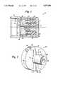
- FIG. 6is a view like that of FIG. 1 for a second exemplary embodiment of motor according to the invention.
- FIG. 7is a schematic of circuitry that may be utilized with the motor of FIG. 6;
- FIG. 8is an end detail view of the rings of the rotor for the motor of FIG. 6.
- the motorincludes a stator 12 having first and second windings (shown collectively at 12) associated therewith, and a rotor 13.
- the rotor 13has permanent magnets mounted on the interior surface thereof, indicated by reference numerals 14 and 15 in FIGS. 1, 3 and 4, one set of magnets (14) having interior surfaces thereof as magnet south poles, while the other set (15) has the interior surface thereof as north poles.
- the rotor 13,which may comprise a tube open at one end and closed at the other, is mounted for rotation by a shaft 17, received by a bearing means 18 interior of the stator 11.
- the stator 11preferably comprises two structures, first and second stator core structures 22, 22', which may be substantially (i.e. exactly or almost) identical.
- the stator first core structure 22is seen more clearly in FIG. 2.
- the stator structure 22comprises a central portion 24 of magnetizable material, which may have a central through-extending opening 23 (see FIG. 1) therein.
- the ends of the central section 24are enlarged end terminations 25, 26 respectively.
- Connected to or integral with the central section 24'is the tubular element 27, also of magnetizable material having an interior through-extending passage 29 which is aligned with the opening 23.
- the magnetizable material forming the components 24, 25, 26 and 27preferably comprises powdered iron.
- the powdered ironmay be doubly coated, for example with phosphate and thermoplastic coatings.
- the volume between the end terminations 25, 26 and the central section 26is preferably filled with a non-magnetizable material, such as the epoxy 30. This results in a construction of an element 22 which comprises a disc, with the tubular element 27 extending outwardly from the center thereof.
- the end terminations 25, 26preferably have primarily arcuate surfaces 28 which are the most remote (radially) portions of the pole pieces from central opening 23 and tubular element 27. However, in order to allow easy start-up of the motor 10, the surfaces 28 must have discontinuities therein. Discontinuities preferably are provided by the flat surfaces 31 seen in FIG. 2.
- the construction of the second stator core structure 22'is substantially the same as the construction of the first structure 22.
- the housing 21 for the circuit board 20may be connected to the stator core structure 22 by adhesive, as indicated at 32 in FIG. 1, and/or by one or more holding pins 33 (preferably two pins 33 are provided, only one of which is seen in FIG. 1).
- Each pin 33may have a polygon construction or the like, or may comprise a key fitting within a keyway in the central passage 23.
- FIGS. 1 through 3a four pole motor is illustrated for ease of explanation.
- the motor 10may have as many poles as any conventional brushless motor constructions.
- the flux from the north poles of the rotorthat is, the magnets 15
- the stator structure (22')aligned with the magnets 15, through the other stator structure (22) to the south poles 14 on the rotor 13, and back to the north poles with the rotor turn path.
- the central structures 24, 24' of the pole pieces 22, 22'are in planes that are parallel to each other (perpendicular to the openings 29, 29'), however, the central sections 24, 24' themselves are perpendicular to each other, as illustrated schematically in FIG. 3.
- stator windings 12-1 or 12-2are supplied with current, a leading magnetic field is created on the stator, which pulls the rotor field and a traction torque is then produced.
- the electronic circuit board 20 circuitrycommutes one winding (e.g., 12-1) to the other (12-2). Commutation takes place periodically when the fields are aligned, as illustrated in FIG. 3.
- FIG. 4illustrates an exemplary rotor structure 13, comprising an end wall 35 having an opening 36 therein for the shaft 17, and a tubular body 37.
- the magnets 14, 15are mounted on the interior of the body 37 .
- the magnets 14, 15may be discrete elements, as illustrated in the schematic representation in FIG. 3. However, preferably they are rings so that they are easier to assemble, as will be described hereafter.
- Exemplary circuitry mounted on the circuit board 20 for effecting commutationis illustrated generally by reference numeral 40 in FIG. 5.
- the circuitry 40comprises first and second transistors 41, 42 connected to the stator windings 12-1, 12-2, respectively, at one end thereof, the other end of each winding 12 being connected to a D.C. power source 43 (e.g. a 12 volt emf source).
- the opposite ends of the transistors 41, 42are connected to ground.
- the circuit 44having capacitor 45 and resistor 46, is connected between the stator winding 12-1 and the second transistor 42, while another circuit 47 includes the capacitor 48 and resistor 49 connected between the stator winding 12-2 or the first transistor 41.
- the collector--coupled pairoperates as a multivibrator with a frequency of ##EQU1##
- Ris the value of resistor 46 or 49 and C is the value of capacitor 45 or 48.
- Resistors 46, 49are also for adjusting the speed of the motor 10.
- An AND gatemay be connected up to the second transistor 42, through a resistor 51, as illustrated in FIG. 5.
- the AND gate 50ensures alignment of the rotor 13 and stator 12, so that the rotor 13 will rotate in one direction only.
- the AND gate 50is connected to the power source 43 and ground through circuit elements 52.
- FIG. 6illustrates a second exemplary embodiment of a motor 110 according to the present invention.
- the FIG. 6 embodiment(various features thereof are shown in FIGS. 7 and 8) structures comparable to those in the FIGS. 1 through 5 embodiment are shown by the same reference numerals only preceded by "1".
- FIGS. 1 and 6One primary difference between the embodiments of FIGS. 1 and 6 is the particular manner in which the shaft 17, 117 for the rotor 13, 113 is mounted.
- the circuitry means 140is different, stator windings 112-1, 112-2 being connected up to the switches 53, 54.
- FIG. 6shows three leads 55 through 57 from the windings 112, and FIG. 7 shows those same leads 55-57.
- the switches 53, 54may be operated by any suitable automatic means for commutation of the windings 112-1, 112-2.
- FIG. 8also shows the magnetic rings 115, 114 as complete rings.
- the rings 114, 115are of magnetizable material, and they are magnetized so that the ring 114 south pole is the interior surface 59, while on the ring 115 the north pole is the interior surface 60.
- the rings 114, 115are magnetized so that magnetic sections are separated by non-magnetized sections 61, 62, this being the construction for a four pole motor, but other constructions may be provided for different numbers of poles.
- rings 114, 115instead of discrete magnets, it is much easier to attach (e.g., with adhesive) the magnets to the interior surface of the cylindrical wall 137 of the rotor 113.
- the stators 11, 111each have a configuration of a virtual bobbin. That means that the windings 12, 112 may be provided between the discs of the stator structures 22, 22' and 122, 122' as simple circumferential wrappings so that the cost of winding insertion is completely eliminated.
- the bearing 18also acts to mechanically hold the stator core structures 22, 22' together, while in the FIG. 6 embodiment, the tubular elements 127, 127' are either connected together by adhesive, or the bearings 118 are thrust bearings so that a force is supplied pushing the stator core structures 122, 122' together.
Landscapes
- Engineering & Computer Science (AREA)
- Power Engineering (AREA)
- Permanent Magnet Type Synchronous Machine (AREA)
- Iron Core Of Rotating Electric Machines (AREA)
- Brushless Motors (AREA)
Abstract
Description
Claims (22)
Priority Applications (1)
| Application Number | Priority Date | Filing Date | Title |
|---|---|---|---|
| US08/148,516US5677580A (en) | 1993-11-08 | 1993-11-08 | Transversal-flux permanent magnet motor |
Applications Claiming Priority (1)
| Application Number | Priority Date | Filing Date | Title |
|---|---|---|---|
| US08/148,516US5677580A (en) | 1993-11-08 | 1993-11-08 | Transversal-flux permanent magnet motor |
Publications (1)
| Publication Number | Publication Date |
|---|---|
| US5677580Atrue US5677580A (en) | 1997-10-14 |
Family
ID=22526105
Family Applications (1)
| Application Number | Title | Priority Date | Filing Date |
|---|---|---|---|
| US08/148,516Expired - Fee RelatedUS5677580A (en) | 1993-11-08 | 1993-11-08 | Transversal-flux permanent magnet motor |
Country Status (1)
| Country | Link |
|---|---|
| US (1) | US5677580A (en) |
Cited By (10)
| Publication number | Priority date | Publication date | Assignee | Title |
|---|---|---|---|---|
| US6144125A (en)* | 1998-05-11 | 2000-11-07 | Orville J. Birkestrand | Contactless electronic control system for modular motorized wheel hub |
| US6246561B1 (en) | 1998-07-31 | 2001-06-12 | Magnetic Revolutions Limited, L.L.C | Methods for controlling the path of magnetic flux from a permanent magnet and devices incorporating the same |
| US6437529B1 (en) | 1998-05-04 | 2002-08-20 | Comair Rotron, Inc. | Multi-stator motor with independent stator circuits |
| WO2003003548A1 (en)* | 2001-06-26 | 2003-01-09 | Robert Bosch Gmbh | Permanent magnet transversal flux machine |
| FR2828027A1 (en)* | 2001-07-30 | 2003-01-31 | Mbi Diffusion Conseil | Electrical machine has homopolar structure and rotor or stator with ring type electrical windings located between pairs of magnetic frames each frame having axial feet forming evenly spaced poles |
| US6798111B1 (en)* | 2003-11-13 | 2004-09-28 | Petersen Technology Corporation | Plastic encapsulated electrodynamic apparatus |
| US20050040716A1 (en)* | 2002-09-18 | 2005-02-24 | Ralf Schmid | Electric machine designed as a starter, generator or starter-generator for a motor vehicle |
| WO2016016591A3 (en)* | 2014-07-31 | 2016-08-25 | Francecol Technology | Cross-flow, homopolar electrical machine |
| US20170373620A1 (en)* | 2015-01-20 | 2017-12-28 | Techtronic Industries Company Limited | Dual-voltage brushless motor |
| US10978967B2 (en)* | 2015-12-21 | 2021-04-13 | KSB SE & Co. KGaA | PM line-start motor and switch-on method therefor |
Citations (16)
| Publication number | Priority date | Publication date | Assignee | Title |
|---|---|---|---|---|
| US4181866A (en)* | 1977-05-26 | 1980-01-01 | Matsushita Electric Industrial Co., Ltd. | Permanent magnet with reduced thickness at the pole areas for small size d-c motors |
| US4217508A (en)* | 1977-04-08 | 1980-08-12 | Sony Corporation | DC motor |
| US4296341A (en)* | 1977-07-15 | 1981-10-20 | Sodeco-Saia Sa | Self-starting single-phase synchronous motor |
| US4315363A (en)* | 1978-03-15 | 1982-02-16 | General Electric Company | Method of making and securing a leakage flux conducting device |
| US4355249A (en)* | 1978-10-30 | 1982-10-19 | Kenwell Rudolf F | Direct current motor having outer rotor and inner stator |
| US4480208A (en)* | 1981-10-23 | 1984-10-30 | Lucas Industries Public Limited Company | Stator structure for an electromagnetic device |
| US4553075A (en)* | 1983-08-04 | 1985-11-12 | Rotron Incorporated | Simple brushless DC fan motor with reversing field |
| US4575652A (en)* | 1984-09-27 | 1986-03-11 | Synektron Corporation | Permanent magnet motor having high starting torque and narrowly-defined detent zones |
| US4600910A (en)* | 1984-12-21 | 1986-07-15 | Pneumo Corporation | Limited angle torque motor with high torque output multiple coils and increased magnetic centering torque |
| US4612526A (en)* | 1984-12-21 | 1986-09-16 | Pneumo Corporation | Torque motor with high torque poles and magnetic centering spring adjustment |
| US4947065A (en)* | 1989-09-22 | 1990-08-07 | General Motors Corporation | Stator assembly for an alternating current generator |
| US4973866A (en)* | 1989-09-26 | 1990-11-27 | North American Philips Corporation | Variable angle stepper motor |
| US4987331A (en)* | 1989-03-06 | 1991-01-22 | Alex Horng | Non-brush D.C. motor with an improved stator |
| US5015903A (en)* | 1988-08-15 | 1991-05-14 | Pacific Scientific Company | Electronically commutated reluctance motor |
| US5220228A (en)* | 1990-02-16 | 1993-06-15 | Sankyo Seiki Mfg. Co., Ltd. | Rotating electric machine with bevelled armature poles |
| US5382859A (en)* | 1992-09-01 | 1995-01-17 | Unique Mobility | Stator and method of constructing same for high power density electric motors and generators |
- 1993
- 1993-11-08USUS08/148,516patent/US5677580A/ennot_activeExpired - Fee Related
Patent Citations (16)
| Publication number | Priority date | Publication date | Assignee | Title |
|---|---|---|---|---|
| US4217508A (en)* | 1977-04-08 | 1980-08-12 | Sony Corporation | DC motor |
| US4181866A (en)* | 1977-05-26 | 1980-01-01 | Matsushita Electric Industrial Co., Ltd. | Permanent magnet with reduced thickness at the pole areas for small size d-c motors |
| US4296341A (en)* | 1977-07-15 | 1981-10-20 | Sodeco-Saia Sa | Self-starting single-phase synchronous motor |
| US4315363A (en)* | 1978-03-15 | 1982-02-16 | General Electric Company | Method of making and securing a leakage flux conducting device |
| US4355249A (en)* | 1978-10-30 | 1982-10-19 | Kenwell Rudolf F | Direct current motor having outer rotor and inner stator |
| US4480208A (en)* | 1981-10-23 | 1984-10-30 | Lucas Industries Public Limited Company | Stator structure for an electromagnetic device |
| US4553075A (en)* | 1983-08-04 | 1985-11-12 | Rotron Incorporated | Simple brushless DC fan motor with reversing field |
| US4575652A (en)* | 1984-09-27 | 1986-03-11 | Synektron Corporation | Permanent magnet motor having high starting torque and narrowly-defined detent zones |
| US4600910A (en)* | 1984-12-21 | 1986-07-15 | Pneumo Corporation | Limited angle torque motor with high torque output multiple coils and increased magnetic centering torque |
| US4612526A (en)* | 1984-12-21 | 1986-09-16 | Pneumo Corporation | Torque motor with high torque poles and magnetic centering spring adjustment |
| US5015903A (en)* | 1988-08-15 | 1991-05-14 | Pacific Scientific Company | Electronically commutated reluctance motor |
| US4987331A (en)* | 1989-03-06 | 1991-01-22 | Alex Horng | Non-brush D.C. motor with an improved stator |
| US4947065A (en)* | 1989-09-22 | 1990-08-07 | General Motors Corporation | Stator assembly for an alternating current generator |
| US4973866A (en)* | 1989-09-26 | 1990-11-27 | North American Philips Corporation | Variable angle stepper motor |
| US5220228A (en)* | 1990-02-16 | 1993-06-15 | Sankyo Seiki Mfg. Co., Ltd. | Rotating electric machine with bevelled armature poles |
| US5382859A (en)* | 1992-09-01 | 1995-01-17 | Unique Mobility | Stator and method of constructing same for high power density electric motors and generators |
Non-Patent Citations (2)
| Title |
|---|
| Weh et al, "New Permanent Magnet Excited Synchronous Machine with High Efficiency at Low Speeds", ICEM 88, pp. 35-40. |
| Weh et al, New Permanent Magnet Excited Synchronous Machine with High Efficiency at Low Speeds , ICEM 88, pp. 35 40.* |
Cited By (15)
| Publication number | Priority date | Publication date | Assignee | Title |
|---|---|---|---|---|
| US6437529B1 (en) | 1998-05-04 | 2002-08-20 | Comair Rotron, Inc. | Multi-stator motor with independent stator circuits |
| US6144125A (en)* | 1998-05-11 | 2000-11-07 | Orville J. Birkestrand | Contactless electronic control system for modular motorized wheel hub |
| US6246561B1 (en) | 1998-07-31 | 2001-06-12 | Magnetic Revolutions Limited, L.L.C | Methods for controlling the path of magnetic flux from a permanent magnet and devices incorporating the same |
| US6342746B1 (en) | 1998-07-31 | 2002-01-29 | Magnetic Revolutions Limited, L.L.C. | Methods for controlling the path of magnetic flux from a permanent magnet and devices incorporating the same |
| WO2003003548A1 (en)* | 2001-06-26 | 2003-01-09 | Robert Bosch Gmbh | Permanent magnet transversal flux machine |
| WO2003012954A3 (en)* | 2001-07-30 | 2004-02-26 | Mbi Motovariateurs Sarl | Homopolar electric machine |
| FR2828027A1 (en)* | 2001-07-30 | 2003-01-31 | Mbi Diffusion Conseil | Electrical machine has homopolar structure and rotor or stator with ring type electrical windings located between pairs of magnetic frames each frame having axial feet forming evenly spaced poles |
| US20050040716A1 (en)* | 2002-09-18 | 2005-02-24 | Ralf Schmid | Electric machine designed as a starter, generator or starter-generator for a motor vehicle |
| US6894411B2 (en)* | 2002-09-18 | 2005-05-17 | Continental Isad Electronic Systems Gmbh & Co., Ohg | Electric machine designed as a starter, generator or starter-generator for a motor vehicle |
| US6798111B1 (en)* | 2003-11-13 | 2004-09-28 | Petersen Technology Corporation | Plastic encapsulated electrodynamic apparatus |
| WO2016016591A3 (en)* | 2014-07-31 | 2016-08-25 | Francecol Technology | Cross-flow, homopolar electrical machine |
| US10224792B2 (en) | 2014-07-31 | 2019-03-05 | Francecol Technology | Rotary electrical machine with homopolar structure |
| US20170373620A1 (en)* | 2015-01-20 | 2017-12-28 | Techtronic Industries Company Limited | Dual-voltage brushless motor |
| US10367435B2 (en)* | 2015-01-20 | 2019-07-30 | Techtronic Industries Company Limited | Dual-voltage brushless motor |
| US10978967B2 (en)* | 2015-12-21 | 2021-04-13 | KSB SE & Co. KGaA | PM line-start motor and switch-on method therefor |
Similar Documents
| Publication | Publication Date | Title |
|---|---|---|
| US6515390B1 (en) | Electric drive apparatus with a rotor having two magnetizied disks | |
| US6940200B2 (en) | Electric drive | |
| US4719378A (en) | Brushless motor having permanent magnet rotor and salient pole stator | |
| US4725750A (en) | Permanent magnet rotary machine | |
| CA1178636A (en) | Brushless disc-type dc motor or generator | |
| US4114057A (en) | Dynamoelectric machine with inner and outer stators | |
| US6013963A (en) | High efficiency electro-mechanical energy conversion device | |
| US5089730A (en) | Low noise DC electric motor | |
| KR950035004A (en) | Multi-axis electric motor and capacitive vacuum pump coupled to it | |
| US4156168A (en) | Electric motor | |
| US5712521A (en) | Hybrid synchronous machine with transverse magnetic flux | |
| US5677580A (en) | Transversal-flux permanent magnet motor | |
| US4843268A (en) | Asymmetric field electromagnetic motor | |
| US4412144A (en) | Single-phase step motor | |
| EP0431178B1 (en) | Synchronous machine | |
| US4845398A (en) | Armature stator configuration for compound interaction/induction electric rotating machine | |
| US4701656A (en) | Electromechanical device with slotted stator | |
| RU96108430A (en) | FAN MOTOR WITH PERMANENT MAGNETS | |
| US4476406A (en) | Generator | |
| EP1209798A1 (en) | Wound salient-pole type rotor for an electric machine | |
| JP2945441B2 (en) | Motor using permanent magnet | |
| KR20000001924A (en) | Electric motor | |
| KR200171918Y1 (en) | Rotor for motor | |
| KR100479080B1 (en) | Line-Started Permanent Magnet Motor | |
| KR19990047517A (en) | Electric motor and its manufacturing method |
Legal Events
| Date | Code | Title | Description |
|---|---|---|---|
| AS | Assignment | Owner name:SL MONTEVIDEO TECHNOLOGY, INC., MINNESOTA Free format text:ASSIGNMENT OF ASSIGNORS INTEREST;ASSIGNOR:HUANG, HAO;REEL/FRAME:006765/0461 Effective date:19931029 | |
| FEPP | Fee payment procedure | Free format text:PAYOR NUMBER ASSIGNED (ORIGINAL EVENT CODE: ASPN); ENTITY STATUS OF PATENT OWNER: LARGE ENTITY | |
| FPAY | Fee payment | Year of fee payment:4 | |
| AS | Assignment | Owner name:MELLON BANK, N.A., PENNSYLVANIA Free format text:SECURITY AGREEMENT;ASSIGNORS:SL INDUSTRIES, INC.;CEDAR CORPORATION;CONDOR D.C. POWER SUPPLIES, INC.;AND OTHERS;REEL/FRAME:012312/0902 Effective date:20011213 | |
| AS | Assignment | Owner name:SL MONTEVIDEO TECHNOLOGY, INC., NEW JERSEY Free format text:TERMINATION OF SECURITY INTEREST;ASSIGNOR:MELLON BANK, N.A.;REEL/FRAME:012698/0429 Effective date:20020226 | |
| AS | Assignment | Owner name:GE CAPITAL CFE, INC., ILLINOIS Free format text:SECURITY AGREEMENT;ASSIGNOR:SL MONTEVIDEO TECHNOLOGY, INC.;REEL/FRAME:012754/0554 Effective date:20020226 | |
| AS | Assignment | Owner name:SL DELAWARE, INC., DELAWARE Free format text:TERMINATION OF SECURITY INTEREST;ASSIGNOR:GE CAPITAL CFE, INC.;REEL/FRAME:013634/0721 Effective date:20021220 Owner name:SL INDUSTRIES, INC., NEW JERSEY Free format text:TERMINATION OF SECURITY INTEREST;ASSIGNOR:GE CAPITAL CFE, INC.;REEL/FRAME:013634/0721 Effective date:20021220 | |
| AS | Assignment | Owner name:LASALLE BUSINESS CREDIT, LLC, PENNSYLVANIA Free format text:SECURITY AGREEMENT;ASSIGNORS:SL INDUSTRIES, INC.;SL DELAWARE, INC.;SL DELAWARE HOLDINGS, INC.;AND OTHERS;REEL/FRAME:013634/0746 Effective date:20030106 | |
| REMI | Maintenance fee reminder mailed | ||
| AS | Assignment | Owner name:BANK OF AMERICA, N.A., AS AGENT, PENNSYLVANIA Free format text:ASSIGNMENT OF ASSIGNORS INTEREST;ASSIGNORS:CONDOR DC POWER SUPPLIES, INC.;TEAL ELECTRONICS CORPORATION;RFL ELECTRONICS CORPORATION;AND OTHERS;REEL/FRAME:016945/0281 Effective date:20050803 | |
| AS | Assignment | Owner name:SLW HOLDINGS, INC., NEW JERSEY Free format text:ASSIGNMENT OF ASSIGNORS INTEREST;ASSIGNOR:LASALLE BUSINESS CREDIT, LLC;REEL/FRAME:016987/0824 Effective date:20050803 Owner name:RFL ELECTRONICS, INC., NEW JERSEY Free format text:ASSIGNMENT OF ASSIGNORS INTEREST;ASSIGNOR:LASALLE BUSINESS CREDIT, LLC;REEL/FRAME:016987/0824 Effective date:20050803 Owner name:SL MONTEVIDEO TECHNOLOGY, INC., NEW JERSEY Free format text:ASSIGNMENT OF ASSIGNORS INTEREST;ASSIGNOR:LASALLE BUSINESS CREDIT, LLC;REEL/FRAME:016987/0824 Effective date:20050803 Owner name:SL INDUSTRIES, INC., NEW JERSEY Free format text:ASSIGNMENT OF ASSIGNORS INTEREST;ASSIGNOR:LASALLE BUSINESS CREDIT, LLC;REEL/FRAME:016987/0824 Effective date:20050803 Owner name:CONDOR D.C. POWER SUPPLIES, INC., NEW JERSEY Free format text:ASSIGNMENT OF ASSIGNORS INTEREST;ASSIGNOR:LASALLE BUSINESS CREDIT, LLC;REEL/FRAME:016987/0824 Effective date:20050803 Owner name:SL DELAWARE, INC., NEW JERSEY Free format text:ASSIGNMENT OF ASSIGNORS INTEREST;ASSIGNOR:LASALLE BUSINESS CREDIT, LLC;REEL/FRAME:016987/0824 Effective date:20050803 Owner name:SL DELAWARE HOLDINGS, INC., NEW JERSEY Free format text:ASSIGNMENT OF ASSIGNORS INTEREST;ASSIGNOR:LASALLE BUSINESS CREDIT, LLC;REEL/FRAME:016987/0824 Effective date:20050803 Owner name:SL SURFACE TECHNOLOGIES, INC., NEW JERSEY Free format text:ASSIGNMENT OF ASSIGNORS INTEREST;ASSIGNOR:LASALLE BUSINESS CREDIT, LLC;REEL/FRAME:016987/0824 Effective date:20050803 Owner name:CEDAR CORPORATION, NEW JERSEY Free format text:ASSIGNMENT OF ASSIGNORS INTEREST;ASSIGNOR:LASALLE BUSINESS CREDIT, LLC;REEL/FRAME:016987/0824 Effective date:20050803 Owner name:TEAL ELECTRONICS CORPORATION, NEW JERSEY Free format text:ASSIGNMENT OF ASSIGNORS INTEREST;ASSIGNOR:LASALLE BUSINESS CREDIT, LLC;REEL/FRAME:016987/0824 Effective date:20050803 Owner name:SL AUBURN, INC., NEW JERSEY Free format text:ASSIGNMENT OF ASSIGNORS INTEREST;ASSIGNOR:LASALLE BUSINESS CREDIT, LLC;REEL/FRAME:016987/0824 Effective date:20050803 Owner name:WABER POWER, LTD., NEW JERSEY Free format text:ASSIGNMENT OF ASSIGNORS INTEREST;ASSIGNOR:LASALLE BUSINESS CREDIT, LLC;REEL/FRAME:016987/0824 Effective date:20050803 Owner name:CONDOR HOLDINGS, INC., NEW JERSEY Free format text:ASSIGNMENT OF ASSIGNORS INTEREST;ASSIGNOR:LASALLE BUSINESS CREDIT, LLC;REEL/FRAME:016987/0824 Effective date:20050803 | |
| LAPS | Lapse for failure to pay maintenance fees | ||
| STCH | Information on status: patent discontinuation | Free format text:PATENT EXPIRED DUE TO NONPAYMENT OF MAINTENANCE FEES UNDER 37 CFR 1.362 | |
| FP | Lapsed due to failure to pay maintenance fee | Effective date:20051014 | |
| AS | Assignment | Owner name:BANK OF AMERICA, N.A., PENNSYLVANIA Free format text:SECURITY AGREEMENT;ASSIGNORS:SL INDUSTRIES, INC.;SL DELAWARE, INC.;SL DELAWARE HOLDINGS, INC.;AND OTHERS;REEL/FRAME:021731/0146 Effective date:20081023 | |
| AS | Assignment | Owner name:SL INDUSTRIES, INC., NEW JERSEY Free format text:RELEASE BY SECURED PARTY;ASSIGNOR:BANK OF AMERICA, N.A.;REEL/FRAME:028795/0546 Effective date:20120809 Owner name:SL DELAWARE, INC., NEW JERSEY Free format text:RELEASE BY SECURED PARTY;ASSIGNOR:BANK OF AMERICA, N.A.;REEL/FRAME:028795/0546 Effective date:20120809 Owner name:SL DELAWARE HOLDINGS, INC., NEW JERSEY Free format text:RELEASE BY SECURED PARTY;ASSIGNOR:BANK OF AMERICA, N.A.;REEL/FRAME:028795/0546 Effective date:20120809 Owner name:MTE CORPORATION, NEW JERSEY Free format text:RELEASE BY SECURED PARTY;ASSIGNOR:BANK OF AMERICA, N.A.;REEL/FRAME:028795/0546 Effective date:20120809 Owner name:RFL ELECTRONICS INC., NEW JERSEY Free format text:RELEASE BY SECURED PARTY;ASSIGNOR:BANK OF AMERICA, N.A.;REEL/FRAME:028795/0546 Effective date:20120809 Owner name:SL MONTEVIDEO TECHNOLOGY, INC., NEW JERSEY Free format text:RELEASE BY SECURED PARTY;ASSIGNOR:BANK OF AMERICA, N.A.;REEL/FRAME:028795/0546 Effective date:20120809 Owner name:CEDAR CORPORATION, NEW JERSEY Free format text:RELEASE BY SECURED PARTY;ASSIGNOR:BANK OF AMERICA, N.A.;REEL/FRAME:028795/0546 Effective date:20120809 Owner name:TEAL ELECTRONICS CORPORATION, NEW JERSEY Free format text:RELEASE BY SECURED PARTY;ASSIGNOR:BANK OF AMERICA, N.A.;REEL/FRAME:028795/0546 Effective date:20120809 Owner name:MEX HOLDINGS LLC, NEW JERSEY Free format text:RELEASE BY SECURED PARTY;ASSIGNOR:BANK OF AMERICA, N.A.;REEL/FRAME:028795/0546 Effective date:20120809 Owner name:SL POWER ELECTRONIC CORPORATION, NEW JERSEY Free format text:RELEASE BY SECURED PARTY;ASSIGNOR:BANK OF AMERICA, N.A.;REEL/FRAME:028795/0546 Effective date:20120809 Owner name:SLGC HOLDINGS, INC., NEW JERSEY Free format text:RELEASE BY SECURED PARTY;ASSIGNOR:BANK OF AMERICA, N.A.;REEL/FRAME:028795/0546 Effective date:20120809 Owner name:SLW HOLDINGS, INC., NEW JERSEY Free format text:RELEASE BY SECURED PARTY;ASSIGNOR:BANK OF AMERICA, N.A.;REEL/FRAME:028795/0546 Effective date:20120809 Owner name:SL AUBURN, INC., NEW JERSEY Free format text:RELEASE BY SECURED PARTY;ASSIGNOR:BANK OF AMERICA, N.A.;REEL/FRAME:028795/0546 Effective date:20120809 Owner name:SL SURFACE TECHNOLOGIES, INC., NEW JERSEY Free format text:RELEASE BY SECURED PARTY;ASSIGNOR:BANK OF AMERICA, N.A.;REEL/FRAME:028795/0546 Effective date:20120809 Owner name:CONDOR D.C. POWER SUPPLIES, INC., NEW JERSEY Free format text:RELEASE BY SECURED PARTY;ASSIGNOR:BANK OF AMERICA, N.A.;REEL/FRAME:028795/0619 Effective date:20120809 Owner name:PNC BANK, NATIONAL ASSOCIATION, PENNSYLVANIA Free format text:SECURITY AGREEMENT;ASSIGNORS:SL INDUSTRIES, INC.;MTE CORPORATION;SL DELAWARE HOLDINGS, INC.;AND OTHERS;REEL/FRAME:028802/0081 Effective date:20120809 |