US5677476A - Sensor and transmitter with multiple outputs - Google Patents
Sensor and transmitter with multiple outputsDownload PDFInfo
- Publication number
- US5677476A US5677476AUS08/597,207US59720796AUS5677476AUS 5677476 AUS5677476 AUS 5677476AUS 59720796 AUS59720796 AUS 59720796AUS 5677476 AUS5677476 AUS 5677476A
- Authority
- US
- United States
- Prior art keywords
- signal
- coupled
- output
- input
- pin
- Prior art date
- Legal status (The legal status is an assumption and is not a legal conclusion. Google has not performed a legal analysis and makes no representation as to the accuracy of the status listed.)
- Expired - Fee Related
Links
- 230000004044responseEffects0.000claimsabstractdescription35
- 239000003990capacitorSubstances0.000description42
- 238000010586diagramMethods0.000description11
- 238000000034methodMethods0.000description10
- 230000008569processEffects0.000description10
- 230000005540biological transmissionEffects0.000description7
- 238000002955isolationMethods0.000description7
- 238000004891communicationMethods0.000description5
- 238000005516engineering processMethods0.000description5
- 239000011324beadSubstances0.000description4
- 238000004364calculation methodMethods0.000description4
- 229910000859α-FeInorganic materials0.000description4
- 230000004888barrier functionEffects0.000description3
- 239000000523sampleSubstances0.000description3
- 230000003750conditioning effectEffects0.000description2
- 230000005284excitationEffects0.000description2
- 238000005259measurementMethods0.000description2
- 101100339482Colletotrichum orbiculare (strain 104-T / ATCC 96160 / CBS 514.97 / LARS 414 / MAFF 240422) HOG1 geneProteins0.000description1
- 230000001143conditioned effectEffects0.000description1
- 230000001419dependent effectEffects0.000description1
- 238000007435diagnostic evaluationMethods0.000description1
- 230000007257malfunctionEffects0.000description1
- 238000007620mathematical functionMethods0.000description1
- 238000012986modificationMethods0.000description1
- 230000004048modificationEffects0.000description1
- 239000011224oxide ceramicSubstances0.000description1
- 229910052574oxide ceramicInorganic materials0.000description1
- TWNQGVIAIRXVLR-UHFFFAOYSA-Noxo(oxoalumanyloxy)alumaneChemical compoundO=[Al]O[Al]=OTWNQGVIAIRXVLR-UHFFFAOYSA-N0.000description1
- 239000000758substrateSubstances0.000description1
- 238000012546transferMethods0.000description1
Images


Classifications
- G—PHYSICS
- G01—MEASURING; TESTING
- G01K—MEASURING TEMPERATURE; MEASURING QUANTITY OF HEAT; THERMALLY-SENSITIVE ELEMENTS NOT OTHERWISE PROVIDED FOR
- G01K1/00—Details of thermometers not specially adapted for particular types of thermometer
- G01K1/02—Means for indicating or recording specially adapted for thermometers
- G01K1/026—Means for indicating or recording specially adapted for thermometers arrangements for monitoring a plurality of temperatures, e.g. by multiplexing
- G—PHYSICS
- G01—MEASURING; TESTING
- G01N—INVESTIGATING OR ANALYSING MATERIALS BY DETERMINING THEIR CHEMICAL OR PHYSICAL PROPERTIES
- G01N27/00—Investigating or analysing materials by the use of electric, electrochemical, or magnetic means
- G01N27/02—Investigating or analysing materials by the use of electric, electrochemical, or magnetic means by investigating impedance
- G01N27/22—Investigating or analysing materials by the use of electric, electrochemical, or magnetic means by investigating impedance by investigating capacitance
- G01N27/223—Investigating or analysing materials by the use of electric, electrochemical, or magnetic means by investigating impedance by investigating capacitance for determining moisture content, e.g. humidity
- G—PHYSICS
- G01—MEASURING; TESTING
- G01W—METEOROLOGY
- G01W1/00—Meteorology
- G01W1/02—Instruments for indicating weather conditions by measuring two or more variables, e.g. humidity, pressure, temperature, cloud cover or wind speed
Definitions
- the present inventionrelates to a moisture sensor and transmitter, and particularly to a moisture sensor and transmitter with multiple outputs. More particularly, the present invention relates to an improved loop powered relative humidity and temperature sensing apparatus with multiple electrically isolated outputs.
- Moisture measuring systemsare well known for sensing moisture in a process pipe.
- Typical systemsinclude remote transmitters with microprocessor electronics, a sensor element mounted in a probe, a flow chamber, a weather-proof enclosure and assorted fittings.
- the moisture probecan be installed onto a process pipe in a variety of ways.
- the moisture sensorcan be mounted in an in-line mounting in a pipe, mounted in a pipe expansion, mounted in an elbow for small pipe diameters, or mounted in a by-pass line to facilitate removal of the moisture probe. See, for example, U.S. patent application Ser. No. 08/254,323 filed Jun. 6, 1994, which discloses such a moisture sensor and transmitter as well as a calibration therefor.
- Conventional 4-20 mA loop powered transmittersare able to measure one or two process variables and can transmit one parameter by way of the loop. If it is desired to transmit more than one parameter using conventional 4-20 mA loop powered transmitters, additional individual 4-20 mA loop powered transmitters and additional power supplies are required.
- both the temperature and the relative humidityare parameters that are required to determine the quantity of moisture in the room.
- the usertypically provides both of these parameters to a programmable logic controller (PLC) or controller from individual loop powered transmitters so that the PLC or controller can calculate the desired quantified moisture units such as the absolute humidity or the mixing ratio.
- PLCprogrammable logic controller
- a single transmitterthat can provide multiple outputs. Such transmitter could receive inputs from several sensors and provide several outputs without requiring additional powered transmitters. Users would particularly appreciate a measuring transmitter assembly that could manipulate the input signals from the sensors so that the output signals carried by the output loops indicate calculated quantified moisture units such as absolute humidity or mixing ratios. In addition, both manufacturers and users would appreciate a measuring transmitter assembly having multiple loops that are electrically isolated so that a single "common" ground connection could be used to ground all of the output loop circuits at the power supply allowing for the use of a single DC power supply to supply power to each of the loops.
- a measuring transmitter assemblyuses the same lines for power input and output signals.
- the measuring transmitter assemblyincludes a first sensor for providing a first input signal in response to the value of a first parameter.
- the measuring transmitteralso includes a second sensor for providing a second input signal in response to the value of a second parameter.
- a transmitteris coupled to the first and second sensors.
- the transmitterincludes a first output loop providing a first output signal in response to the first input signal and a second output loop providing a second output signal in response to the second input signal.
- the measuring transmitter in accordance with the present inventionincludes a first output loop providing a first output signal having a current that varies between 4 and 20 milliamps in response to a first input signal and a second output loop providing a second output signal having a current that varies between 4 and 20 milliamps in response to the second input signal.
- the first and second loopsare electrically isolated by a digital isolator.
- the preferred digital isolatordraws a current of 60 microamperes or less.
- the low power consumption of the digital isolatorallows the measuring transmitter to include multiple isolated loops, each loop having a current that varies between 4 and 20 milliamps.
- the low power consumption of the digital isolatorallows the illustrative transmitter to utilize as many as all four pulse width modulation (PWM) outputs provided by the illustrative microcontroller so that the transmitter can include up to four output loop circuits.
- PWMpulse width modulation
- the transmittercould, for example, receive input signals from each of a first sensor, a second sensor, a third sensor, and a fourth sensor.
- the low power consumption of the digital isolatorallows each of the first, second, third, and fourth output loop circuits to be electrically isolated.
- each of the output loop circuitsincludes an independent ground portion that is maintained at a ground potential. Electrically isolating each of the output loop circuits allows for connecting the ground portions of each output loop at the power source to a single "common" ground connection. If the output loop circuits were not electrically isolated, the use of a common ground could result in interference between the output signals, potentially causing a malfunction of the transmitter. However, electrically isolating each of the output loop circuits allows for the use of a common ground at the power source without any of the output signals being affected by any of the other output signals.
- the measuring transmitter assembly in accordance with the present inventioncan have process measurement signals that are provided to a single central microcontroller.
- the microcontrollercalculates selected output parameters selected on the basis of a "unit's input signal" provided to the microcontroller in response to the position of a unit switch.
- the microcontrollertherefore, performs various mathematical functions on the input signals to determine the values of calculated parameters in order to provide "calculated output signals" that vary in response to the values of the calculated parameters and that are readily usable by a user without having to be processed through an external PLC or an external controller.
- These output signalsare transmitted to the user by way of 4-20 mA output loop circuits.
- the 4-20 mA output loop circuitsare electrically isolated. Electrically isolating the output circuits allows the user to "common" the grounds of the output loops at the power supply without causing any interference between or in some other way affecting any of the output signals. This also allows the user to operate the measuring transmitter assembly with only one power supply providing power for all of the loops rather than providing a separate power supply for each loop. In addition, the low current consumption of the isolation barrier of the measuring transmitter assembly in accordance with the present invention allows for the use of multiple isolated 4-20 mA loop output circuits providing multiple 4-20 mA output signals.
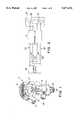
- FIG. 1is a perspective view with portions broken away illustrating details of a transmitter in accordance with the present invention for generating multiple output signals, such output signals optionally being proportional to measured parameters such as relative humidity and temperature detected by sensors and calculated parameters such as the dew point, the mixing ratio, and the absolute humidity that can be derived from the measured parameters;
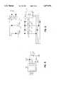
- FIG. 2is a block diagram illustrating the transmitter of FIG. 1 coupled to a process pipe, showing two sensors detecting parameters related to the contents of the pipe, the sensors providing signals to the transmitter, a power supply for providing power to the transmitter, and transmission loops connecting the power supply to the transmitter and carrying the transmitted signals from the transmitter to measuring resistors on the transmission loops for measuring the signals transmitted by the transmitter;
- FIG. 3is a block diagram illustrating the electronic circuitry of the transmitter and showing illustrative temperature and trace or relative humidity sensors, a microcontroller that receives conditioned signals originating from the sensors, an EEPROM that stores and provides data to the microcontroller, and a switch that provides an input to the microcontroller in response to the configuration of the switch, a first transmission loop coupled to the microcontroller for transmitting an output signal from the microcontroller to the receiver (not shown), and a second transmission loop coupled to the microcontroller for transmitting a second output signal from the microcontroller to the receiver;
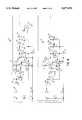
- FIG. 4is a schematic diagram of the sensor conditioning and digitizing circuitry that illustratively receives two analog signals from the sensors and provides a digital signal in response to each analog signal received;
- FIG. 5is a schematic diagram of the EEPROM that stores calibration data and calculation data used during the calculation of derived values from the measured parameters, the calculation and calibration data being stored for use by the microcontroller;
- FIG. 6is a schematic diagram of a binary coded decimal (BCD) selector switch and calibration switches that provide calibration and unit selection inputs to the microcontroller;
- BCDbinary coded decimal
- FIG. 7is a schematic diagram of an RS-485 interface that allows for the uploading and downloading of calibration data between the transmitter and a data transfer unit (not shown) as well as for diagnostic evaluation of the transmitter;
- FIG. 8is a schematic diagram of a microcontroller that links the RS-485 interface with the EEPROM and that provides output signals proportional to the measured and derived parameters in response to inputs from the sensors, the switches, and the EEPROM;
- FIG. 9is a schematic diagram of two separate and electrically isolated transmission loops, each loop transmitting an output signal proportional to the value of a measured or derived parameter;
- FIG. 10is a schematic diagram of a voltage regulator that provides electrical power to the first loop and that provides electrical power to various portions of the transmitter circuit;
- FIG. 11is a schematic diagram of a second voltage regulator that provides electrical power to the second loop, a comparator, and a digital isolator that isolates the first loop from the second loop.
- FIG. 1illustrates a transmitter 10 having an outer housing 12, a threaded cap portion 14, and a power signal cable entry 16.
- transmitter 10is a DewPro MMR30 relative humidity moisture transmitter available from Endress+Hauser located in Greenwood, Ind.
- Transmitter 10includes a flow cell 18 coupled to housing 12. Two sensor elements 20 are mounted within flow cell 18.
- Transmitter 10also includes a threaded inlet or process connection 22 having a sintered filter 24 mounted therein.
- Transmitter 10also includes an outlet or exhaust fitting 26 threadably coupled to flow cell 18. During normal operation, a plug having an orifice therein to bleed off process air is machined into the outlet fitting 26.
- transmitter 10provides two two-wire output signals represented by two 4-20 mA loop currents which are directly proportional to measured or derived parameters such as the temperature and the relative humidity or the dew point.
- sensor elements 20are relative humidity or trace moisture sensor elements operating under the capacitance principle. Sensor elements 20 are preferably mounted on an aluminum oxide ceramic substrate and have a reduced temperature coefficient. Typically, transmitter 10 is calibrated at the factory to precise National Institute of Standards and Technology (NIST) certified moisture references and has an accuracy of within ⁇ 2% relative humidity (RH) or ⁇ 2° C. dew point respectively.
- NISTNational Institute of Standards and Technology
- Transmitter 10can accept input signals from a plurality of sensor elements 20 as shown diagrammatically in FIG. 2. Illustratively, transmitter 10 is mounted so that sensor elements 20 detect parameters related to the contents of process pipe 28. Transmitter 10 is illustratively connected to two isolated transmission loops 34, 36, each loop 34, 36 transmitting an output signal proportional either to the measured parameters or to parameters derived from the measured parameters. The output signal associated with loop 34 is measured at terminals 46 adjacent to a first measuring resistor 47 and the output signal associated with loop 36 is measured at terminals 48 adjacent to a second measuring resistor 49.
- Transmission loops 34, 36also operate to supply electrical power to transmitter 10. Isolating loops 34, 36, inside of transmitter 10 rather than at power supply 38 allows for powering both loops 34, 36 from the same power supply and for connecting the ground portion of each loop 34, 36 to a single "common" ground connection at the power supply.
- FIG. 3is a block diagram of the electronics of an illustrative transmitter 10 that provides two two-wire output signals in response to input signals from sensors 20, illustratively including an RH sensor 42 and a temperature sensor 44.
- a microcontroller 50is provided for controlling the electronics to process information from sensors 42, 44, an EEPROM 58, and an RS-485 communication interface 68 and to provide signals to loops 34, 36.
- An RS-485 communication interface 68is coupled to microcontroller 50.
- Interface 68is configured to be coupled to transmitter 10 by terminals 76, 78 of a calibration interface to permit a calibrator (not shown) to calibrate transmitter 10.
- a calibratornot shown
- datais transmitted from the calibrator to EEPROM 58 through microcontroller 50.
- EEPROM 58Calibration data is stored in EEPROM 58 as shown 35 in FIG. 3.
- EEPROM 58is electrically coupled to I/O pins of microcontroller 50.
- a first voltage regulator 60is provided to supply power to the various electronic components of transmitter 10 including a first loop control circuit 30.
- a second voltage regulator 62is provided to supply power to various other electronic components of transmitter 10 including a second loop control circuit 32.
- First loop control circuit 30is provided to generate a first output signal ranging from 4-20 mA indicative of the parameters of interest measured by a first sensor 20 or mathematically derived from parameters measured by both sensors 20.
- Second loop control circuit 32is provided to generate a second output signal ranging from 4-20 mA indicative of the parameters of interest measured by another of sensors 20.
- the output from loop control 30 across terminals 64, 66is a dew point temperature in °C. or °F.
- transmitter 10 in accordance with the present inventioncan be configured to include a third loop control circuit (not shown) to generate a third output signal ranging from 4-20 mA indicative of a parameter of interest and a fourth loop control circuit (not shown) to generate a fourth output signal ranging from 4-20 mA indicative of a parameter of interest.
- Transmitter 10includes a digital isolator 54 to electrically isolate 4-20 mA circuits 30, 32 as shown in FIG. 3.
- Digital isolator 54is illustratively a model number LTC1146 available from Linear Technology. Digital isolator 54 isolates the digital signal from microcontroller 50 and then outputs the signal to the loop control 32.
- Microcontroller 50is illustratively a model number MC68HC705B5 available from Motorola as shown in FIG. 8. Microcontroller 50 receives inputs from sensor excitation and digitizing circuit 52 as shown in FIG. 4, EEPROM 58 as shown in FIG. 5, a unit selector switch 220, and RH calibration switches 234, 236 as shown in FIG. 6, and RS-485 interface 68 shown in FIG. 7.
- Unit selector switch 220is positionable by the user at discrete positions to indicate the desired units of the output signals.
- unit selector switch 220is a #NDR3FR10P binary coded decimal (BCD) selector switch available from NKK.
- RH calibration switches 234, 236are adjustable to cause an adjustment of the output signals and are useful for calibrating transmitter 10.
- RH calibration switches 234, 236are #7914J-1-000 switches available from Bourns.
- Sensor conditioning and digitizing circuit 52 shown in FIG. 4includes connector 190 which is coupled to sensors (not shown in FIG. 4), for example, a Relative Humidity (RH) sensor and a temperature sensor.
- Pin 1 of connector 190is coupled to pin 1 of a 100 uA constant current source 192.
- 100 uA constant current source 192is a Model No. REF200 AU constant current source available from Burr Brown.
- Pin 3 of connector 190is coupled to an internal first ground 90 of transmitter 10.
- Pin 5 of connector 190is coupled to the +5V supply voltage.
- Pin 5 of connector 190is also coupled to pin 8 of 100 uA constant current source 192.
- Pin 4 of connector 190is coupled to a 1K resistor 196.
- 1K resistor 196is coupled to pin 2 of 10 bit analog to digital converter (A/D converter) 194.
- A/D converter 194is a Model No. LTC1298ISA 10 bit analog to digital converter available from Linear Technology.
- the common terminal of resistor 196 and pin 2 of A/D converter 194is coupled to pin 6 of connector 190 through 1 uF capacitor 198.
- the common terminal of pin 6 of connector 190 and 1 uF capacitor 198is coupled to first ground 90.
- the common terminal of pin 6 of connector 190 and of 1 uF capacitor 198is coupled to the +input terminal of operational amplifier 202 at pin 3 through 1 uF capacitor 200.
- the common terminal of pin 1 of connector 190 and pin 1 of 100 uA constant current source 192is connected to the common terminal of the +input terminal of operational amplifier 202 at pin 3 and the 1 uF capacitor 200.
- operational amplifier 202is a model number OP-90GS available from Analog Devices.
- the -input terminal of operational amplifier 202 at pin 2is coupled to first ground 90 through 35K resistor 204.
- the common terminal of pin 2 of operational amplifier 202 and 35K resistor 204is coupled to pin 6 of operational amplifier 202 through 1M resistor 206.
- Pin 4 of operational amplifier 202is coupled to first ground 90.
- Pin 7 of operational amplifier 202is coupled to a +5V supply voltage.
- the common terminal of pin 7 of operational amplifier 202 and the +5V supply voltageis coupled to first ground 90 through 100 nF capacitor 208.
- the common terminal of pin 6 of operational amplifier 202 and 1M resistor 206is coupled to pin 3 of A/D converter 194 as shown in FIG. 4.
- Pin 4 of A/D converter 194is coupled to first ground 90.
- Pin 8 of A/D converter 194is coupled to a +5V power supply.
- the common terminal of pin 8 of A/D converter 194 and the +5V power supplyis coupled to first ground 90 through 10 uF capacitor 210.
- Pin 6 of A/D converter 194is coupled to first ground 90 through 100K resistor 214 and 196K resistor 212.
- the common terminal of 100K resistor 214 and 196K resistor 212is coupled to pin 26 of microcontroller 50.
- Pin 1 of A/D converter 194is coupled to pin 24 of microcontroller 50.
- Pin 7 of A/D converter 194is coupled to pin 27 of microcontroller 50.
- Pin 5 of A/D converter 194is coupled to pin 25 of microcontroller 50.
- the preferred RH sensor(not shown) provides a voltage to connector 190 that is proportional to the RH. This signal is fed into a low pass filter comprising 1K resistor 196 and 1 uF capacitor 198, and then to one of two inputs of A/D converter 194.
- the A/D converter 194digitizes the voltage and provides an output signal of the digital value of the voltage to microcontroller 50 via a 4-wire serial communication link as described above.
- the preferred temperature sensor(not shown) has a variable resistance that varies proportionally with the sensed temperature.
- the 100 uA constant current source 192 and the variable resistance of the temperature sensorcooperate to provide a voltage that varies with the sensed temperature.
- This voltage signalis amplified via operational amplifier 202, 35K resistor 204, and 1M resistor 206.
- the output of operational amplifier 202is received by the A/D converter 194.
- the A/D converter 194digitizes the signal and provides the digital value to microcontroller 50 via the 4-wire serial communication link.
- Microcontroller 50collects the digitized input signals from sensor excitation and digitizing circuit 52 and calculates the actual RH and temperature using these digitized input signals and calibration data stored in EEPROM 58. From RH and temperature, microcontroller 50 then calculates the desired moisture unit, for example, dew point, mixing ratio, or absolute humidity, based on the position of the BCD selector switch 220 as shown in FIG. 6.
- desired moisture unitfor example, dew point, mixing ratio, or absolute humidity
- Pin 1 of selector switch 220 shown in FIG. 6is coupled to pin 31 of microcontroller 50.
- Pin 2 of selector switch 220is coupled to pin 30 of microcontroller 50.
- Pin 4 of selector switch 220is coupled to pin 29 of microcontroller 50.
- Pin 8 of selector switch 220is coupled to pin 28 of microcontroller 50.
- pin 1 of selector switch 220is coupled to 1M resistor 222.
- Pin 2 of selector switch 220is coupled to 1M resistor 224.
- Pin 4 of selector switch 220is coupled to 1M resistor 226.
- Pin 8 of selector switch 220is coupled to 1M resistor 228.
- Resistors 222, 224, 226, 228are coupled in parallel to a +3.3V power supply.
- a common terminal of resistors 222, 224, 226, 228is coupled to pin 42 of microcontroller 50 through a 1M resistor 230. Also, the common terminal of resistors 222, 224, 226, 228 is coupled to pin 43 of microcontroller 50 through 1M resistor 232.
- Pin C of selector switch 220is coupled to first ground 90 as shown in FIG. 6.
- Pin C of selector switch 220is also coupled to push button switches 234, 236 that are used for field recalibration of the RH sensor.
- the common terminal of pin 42 of microcontroller 50 and 1M resistor 230is coupled to first ground 90 through push button switch 234.
- the common terminal of pin 43 of microcontroller 50 and 1M resistor 232is coupled to first ground 90 through push button switch 236.
- a 2 MHz clock 100includes a 2 MHz oscillator 102 coupled in parallel with a 1M resistor 104 between pins 16 and 17 (OSC1 and OSC2) of microcontroller 50 as shown in FIG. 8.
- Pin 1 of low voltage interrupt chip 106is coupled to pin 18 of microcontroller 50.
- Pin 1 of chip 106is also coupled through a 10K resistor 108 to pin 2 of chip 106.
- the common terminal of resistor 108 and pin 2 of chip 106is coupled to the +3.3V supply voltage.
- Pin 4 of chip 106is coupled to first ground 90.
- Chip 106measures the supply voltage and resets the microcontroller 50 if the voltage drops below a preset value.
- Pins 3, 4, 5, 7, 9, 11-14, 22, 23, 32, 33, 34-39, and 41 of microcontroller 50are all coupled to first ground 90 as shown in FIG. 8.
- Pins 8, 10, 15, and 19 of microcontroller 50are coupled to the +3.3V supply voltage.
- Pin 10 of microcontroller 50is coupled through a 100 nF capacitor 110 and 1 uF capacitor 112 which is in parallel to 100 nF capacitor 110 to first ground 90.
- Pin 44 of microcontroller 50is coupled to pin 4 of EEPROM chip 58 as shown in FIG. 5.
- chip 58is a AT93C66-10SI EEPROM chip available from Atmel.
- Pin 45 of microcontroller 50is coupled to pin 3 of chip 58.
- Pin 46 of microcontroller 50is coupled to pin 2 of chip 58.
- Pin 47 of microcontroller 50is coupled to pin 1 of chip 58.
- Pin 5 of chip 58is coupled to first ground 90 as shown in FIG. 5.
- Pin 6 of chip 58is coupled to pin 8 of chip 58.
- the common terminal of pin 6 and pin 8is coupled to the +3.3V supply voltage.
- the common terminal of pins 6 and 8are coupled through a 100 nF capacitor 114 to first ground 90.
- Pin 48 of microcontroller 50is coupled to pin 3 of communication interface chip 116 of RS-485 interface as shown in FIG. 7.
- chip 116is a LTC485 chip available from Linear Tech.
- Pin 49 of microcontroller 50is coupled to pin 2 of chip 116.
- Pin 50 of microcontroller 50is coupled through a 100K resistor 118 to pin 1 of chip 116.
- the common terminal of 100K resistor 118 and pin 50 of microcontroller 50is coupled through a 196K resistor 102 to first ground 90.
- Pin 52 of microcontroller 50is coupled to pin 4 of chip 116.
- Pin 5 of chip 116is coupled to first ground 90.
- Pin 5 of chip 116is also coupled through a 1M resistor 120 to pin 2 of connector 122.
- Pin 6 of chip 116is coupled to pin 1 of connector 122.
- Pin 7 of chip 116is coupled to pin 2 of connector 122.
- Pin 8 of chip 116is coupled to a +5V supply voltage.
- the common terminal of the +5V supply voltage and pin 8 of chip 116is also coupled through a 100 nF capacitor 124 to first ground 90.
- the common terminal of the +5V supply voltage and pin 8 of chip 116is coupled through a 1M resistor 126 to pin 1 of connector 122.
- Pin 2 of microcontroller 50is coupled to first loop control circuit 30 as shown in FIG. 9. Specifically, pin 2 of microcontroller 50 is coupled through a 1M resistor 128, a 1M resistor 130, and a 1M resistor 132 to the +input terminal at pin 1 of operational amplifier 134.
- Operational amplifier 134is a model number LT1078IS8 available from Linear Tech.
- the common terminal of resistors 128 and 130is coupled to first ground 90 through a 100 nF capacitor 136.
- the common terminal of resistors 130 and 132is coupled to first ground 90 through a 100 nF capacitor 138.
- the common terminal of resistor 132 and the +input terminal at pin 1 of operational amplifier 134is coupled through a 100 nF capacitor 140 to first ground 90.
- the common terminal of resistor 132 and the +input terminal at pin 1 of operational amplifier 134is also coupled through a 221 mK resistor 142 and 10 ohm sense resistor 82 to first ground 90.
- a common terminal of resistors 142 and 82is coupled through a ferrite bead 144 to output terminal 66.
- the -input terminal of operational amplifier 134 at pin 8is coupled through a 205K resistor 146 to first ground 90.
- Pin 8 of operational amplifier 134is also coupled through a 100 pF capacitor 148 to the output terminal of operation amplifier 134 at pin 7.
- Pin 2 of operational amplifier 134is coupled to first ground 90.
- Pin 6 of operational amplifier 134is coupled to the +3.3V supply voltage.
- pin 6 of operational amplifier 134is coupled through a 100 nF capacitor 150 to first ground 90.
- the common terminal of capacitor 148 and the output terminal at pin 7 of operational amplifier 134is coupled through a 10K resistor 152 to the base of transistor 154.
- transistor 154is a MJD31 transistor available from Motorola.
- the emitter of transistor 154is coupled to first ground 90.
- the collector of transistor 154is coupled to the cathode of diode 156.
- Diode 156is illustratively a LL4148 diode available from ITT.
- the anode of diode 156is coupled through ferrite bead 158 to terminal 64.
- An overvoltage suppressor 160is coupled to terminal 64 and to terminal 66.
- the common terminal of the cathode of diode 156 and the collector of transistor 154is also coupled to pin 1 of voltage regulator 170 as shown in FIG. 10.
- voltage regulator 170is a LT1121-IST-5.0 regulator available from Linear Tech.
- the common terminal of the cathode of diode 156, the collector of transistor 154, and pin 1 of regulator 170is coupled through a 100 nF capacitor 172 to first ground 90.
- Pin 2 of regulator 170is coupled to first ground 90.
- Pin 3 of regulator 170is coupled to a +5V supply voltage.
- Pin 3 of regulator 170is also coupled through a 1 uF capacitor 174 to first ground 90.
- voltage regulator 176is a LT1121-IST-3.3 regulator available from Linear Tech.
- Pin 2 of regulator 176is coupled to first ground 90.
- Pin 3 of regulator 176is coupled to the +3.3V supply voltage.
- Pin 3 of regulator 176is also coupled through a 1 uF capacitor 178 to first ground 90.
- Pin 1 of microcontroller 50is coupled to pin 1 of digital isolator 54 as shown in FIG. 11.
- digital isolator 54is a LTC1146CN digital isolator available from Linear Technologies.
- Pin 18 of digital isolator 54is coupled to first ground 90.
- Pin 9 of digital isolator 54is coupled to an internal second ground 92 of transmitter 10.
- Pin 10 of digital isolator 54is coupled to pin 3 of a comparator 250.
- Pin 12 of digital isolator 54is coupled to voltage regulator 62 as well as to pin 7 of comparator 250.
- pin 12 of digital isolator 54is coupled to second ground 92 through a 100 nF capacitor 252 as shown in FIG. 11.
- the common terminal of pin 12 of digital isolator 54 and 100 nF capacitor 252is coupled by a common terminal 256 shown in FIG. 11 to second ground 92 through 100 nF capacitor 254 as shown in FIG. 9.
- the common terminal 256 of pin 12 of digital isolator 54, 100 nF capacitor 252, and 100 nF capacitor 254is also coupled to pin 3 of voltage regulator 258 as shown in FIG. 11.
- the common terminal of pin 3 of voltage regulator 258 and terminal 256is coupled to second ground 92 through 1 uF capacitor 260.
- the common terminal of pin 3 of voltage regulator 258 and terminal 256is coupled to pin 7 of operational amplifier 262 as shown in FIG. 9.
- pin 7 of operational amplifier 262is coupled to second ground 92 through 100 nF capacitor 254.
- Illustrative operational amplifier 262is a Model No. LT1077S8 operational amplifier available from Linear Technologies.
- Illustrative comparator 250is a Model No. MAX931ESA comparator available from Maxim. Pins 1 and 2 of comparator 250 are coupled to second ground 92. Pin 3 of comparator 250 is coupled to pin 10 of digital isolator 54. Pin 4 of comparator 250 is coupled to pin 5 of comparator 250. Pin 6 of comparator 250 is coupled to the common terminal of pin 4 of comparator 250 and pin 5 of comparator 250.
- Pin 8 of comparator 250is coupled through a 1M resistor 264, a 1M resistor 266, and a 1M resistor 268 to the +input terminal of operational amplifier 262 at pin 3 as shown in FIG. 9.
- the common terminal of resistors 264 and 266is coupled to second ground 92 through a 100 nF capacitor 270.
- a common terminal of resistors 266 and 268is coupled to second ground 92 through a 100 nF capacitor 272.
- the +input terminal at pin 3 of operational amplifier 262is coupled through a 100 nF capacitor 274 to second ground 92.
- the common terminal of pin 3 of operational amplifier 262, resistor 268, and capacitor 274is also coupled through a 147K resistor 276 and 10 ohm sense resistor 84 to second ground 92.
- a common terminal of resistors 276 and 84is coupled through a ferrite bead 278 to output terminal 72.
- the -input terminal of operational amplifier 262 at pin 2is coupled through a 140K resistor 280 to second ground 92.
- the common terminal of resistor 280 and pin 2 of operational amplifier 262is also coupled through a 22 pF capacitor 282 to the output terminal of operation amplifier 262 at pin 6.
- Pin 4 of operational amplifier 262is coupled to second ground 92.
- the output terminal at pin 6 of operational amplifier 262is coupled through a 10K resistor 284 to the base of transistor 286.
- transistor 286is a MJD31 transistor available from Motorola.
- the emitter of transistor 286is coupled to second ground 92.
- the collector of transistor 286is coupled to the cathode of diode 288.
- Diode 288is illustratively a LL4148 diode available from ITT.
- the anode of diode 288is coupled through ferrite bead 290 to terminal 70.
- An overvoltage suppressor 292is coupled to terminal 70 and to terminal 72.
- the common terminal of the cathode of diode 288 and the collector of transistor 286is also coupled to pin 1 of voltage regulator 258 as shown in FIG. 11.
- voltage regulator 258is a LT1121-IST-5.0 regulator available from Linear Tech.
- Pin 1 of regulator 258is coupled through a 100 nF capacitor 294 to second ground 92.
- Pin 2 of regulator 258is coupled to second ground 92.
- Pin 3 of regulator 258is coupled through a 1 uF capacitor 260 to second ground 92.
- the common terminal of pin 3 of regulator 258 and capacitor 260is coupled to the common terminal 256 of pin 12 of digital isolator 54, 100 nF capacitor 252, 100 nF capacitor 254, and pin 7 of operational amplifier 262 as described above.
- microcontroller 50collects input signals from RH sensor 42 and temperature sensor 44 and calculates the actual RH and temperature using calibration data stored in EEPROM 58 as shown in FIG. 3. Microcontroller 50 then calculates a desired moisture unit such as dew point, mixing ratio, or absolute humidity based on the setting of BCD selector switch 220. A signal corresponding to the selected moisture unit is then output to first 4-20 mA. loop controller 30 from pin 2 of microcontroller 50 in pulse width modulation (PWM) format. PWM format is a square wave in which the frequency is fixed, but the duty cycle varies proportionally with the unit of interest. The PWM values corresponding to 4 mA and 20 mA for the moisture units are calibration values that are stored in EEPROM 58.
- PWMpulse width modulation
- a signal corresponding to the temperatureis output to second 4-20 mA loop controller 32 from pin 1 of microcontroller 50 in PWM format.
- the PWM values corresponding to 4 mA and 20 mA for temperatureare also calibration values that are stored in EEPROM 58.
- other pinsare available on microcontroller 50 to generate digital signals corresponding additional parameters for output to additional 4-20 mA loops.
- the PWM signal from pin 2 of microcontroller 50 to first 4-20 mA loop controller 30is converted from the square wave to an analog voltage via resistors 128, 130, 132, and capacitors 136, 138, 140.
- the analog voltageis then converted into a current by resistors 146, 142, 152, 82, operational amplifier 134, and transistor 154.
- Sense resistor 82allows operational amplifier 134 to compensate for the current consumption of the circuit and therefore maintains an output current directly proportional to the input voltage.
- the PWM signal from pin 1 of microcontroller 50 to second 4-20 mA loop controller 32is electrically isolated by digital isolator 54 and then output to comparator 250.
- Comparator 250maintains a consistent high level and low level amplitude of the PWM signal.
- the amplitude of the output from digital isolator 54varies as changes in the ambient temperature cause the temperature of digital isolator 54 to vary.
- the output from comparator 250is much less temperature dependent and use of comparator 250 virtually eliminates this potential drift error.
- the process measurement signals from sensors 20are provided to a single microcontroller 50, allowing for the calculation of various output values based on the input signals.
- illustrative transmitter 10can provide the raw measured values.
- Illustrative transmitter 10can include up to four 4-20 mA loop control circuits and output loops when additional digital isolators similar to digital isolator 54 are used to isolate the loop control circuits.
- the power consumption of digital isolator 54does not limit transmitter 10 to four 4-20 mA output loops.
- Transmitter 10is limited to four 4-20 mA output loops by the number of PWM outputs available on illustrative microcontroller 50. If more PWM outputs were available on microcontroller 50, transmitter 10 could include additional 4-20 mA output loops without the power consumption of digital isolator 54 affecting the output signals.
- having the loop isolation within transmitter 10allows the multiple loops to be powered by the same power supply and allows for the output loops to be connected to a single common ground at the power supply. If the grounds of the output loops were tied together without isolation, the 4-20 mA signals could interfere with one another and fail to function properly. Instead, isolation of the 4-20 mA loop control circuits in transmitter 10 allows for the use of the common ground at the power source for the output loops at the power supply without affecting the 4-20 mA output signals.
Landscapes
- Life Sciences & Earth Sciences (AREA)
- Environmental & Geological Engineering (AREA)
- General Physics & Mathematics (AREA)
- Physics & Mathematics (AREA)
- Chemical & Material Sciences (AREA)
- General Health & Medical Sciences (AREA)
- Engineering & Computer Science (AREA)
- Biochemistry (AREA)
- Health & Medical Sciences (AREA)
- Electrochemistry (AREA)
- Immunology (AREA)
- Pathology (AREA)
- Analytical Chemistry (AREA)
- Chemical Kinetics & Catalysis (AREA)
- Atmospheric Sciences (AREA)
- Biodiversity & Conservation Biology (AREA)
- Ecology (AREA)
- Environmental Sciences (AREA)
- Arrangements For Transmission Of Measured Signals (AREA)
Abstract
Description
Claims (8)
Priority Applications (1)
| Application Number | Priority Date | Filing Date | Title |
|---|---|---|---|
| US08/597,207US5677476A (en) | 1996-02-06 | 1996-02-06 | Sensor and transmitter with multiple outputs |
Applications Claiming Priority (1)
| Application Number | Priority Date | Filing Date | Title |
|---|---|---|---|
| US08/597,207US5677476A (en) | 1996-02-06 | 1996-02-06 | Sensor and transmitter with multiple outputs |
Publications (1)
| Publication Number | Publication Date |
|---|---|
| US5677476Atrue US5677476A (en) | 1997-10-14 |
Family
ID=24390551
Family Applications (1)
| Application Number | Title | Priority Date | Filing Date |
|---|---|---|---|
| US08/597,207Expired - Fee RelatedUS5677476A (en) | 1996-02-06 | 1996-02-06 | Sensor and transmitter with multiple outputs |
Country Status (1)
| Country | Link |
|---|---|
| US (1) | US5677476A (en) |
Cited By (58)
| Publication number | Priority date | Publication date | Assignee | Title |
|---|---|---|---|---|
| US5922939A (en)* | 1997-03-07 | 1999-07-13 | Veris Industries, Inc. | Humidity sensor |
| WO1999047905A3 (en)* | 1998-03-20 | 1999-11-11 | Cyrano Sciences Inc | Handheld sensing apparatus |
| GB2342171A (en)* | 1998-03-20 | 2000-04-05 | Cyrano Sciences Inc | Handheld sensing apparatus |
| WO1999060541A3 (en)* | 1998-05-20 | 2000-06-02 | Foxboro Co | Measurement circuit employing dual floating power supplies |
| US6085576A (en)* | 1998-03-20 | 2000-07-11 | Cyrano Sciences, Inc. | Handheld sensing apparatus |
| WO2000052444A3 (en)* | 1999-03-03 | 2001-01-11 | Cyrano Sciences Inc | Apparatus, systems and methods for detecting and transmitting sensory data over a computer network |
| WO2001029556A1 (en)* | 1999-10-21 | 2001-04-26 | Johnson Controls Technology Company | Humidity detector calibration method |
| US6484107B1 (en)* | 1999-09-28 | 2002-11-19 | Rosemount Inc. | Selectable on-off logic modes for a sensor module |
| US6487912B1 (en) | 1999-09-28 | 2002-12-03 | Rosemount Inc. | Preinstallation of a pressure sensor module |
| US6504489B1 (en) | 2000-05-15 | 2003-01-07 | Rosemount Inc. | Process control transmitter having an externally accessible DC circuit common |
| US6511337B1 (en) | 1999-09-28 | 2003-01-28 | Rosemount Inc. | Environmentally sealed instrument loop adapter |
| US6546805B2 (en) | 2000-03-07 | 2003-04-15 | Rosemount Inc. | Process fluid transmitter with an environmentally sealed service block |
| US6571132B1 (en) | 1999-09-28 | 2003-05-27 | Rosemount Inc. | Component type adaptation in a transducer assembly |
| US6657443B2 (en)* | 2001-09-04 | 2003-12-02 | Technical Development Consultants, Inc. | Absolute-reading soil moisture and conductivity sensor |
| US20040059509A1 (en)* | 2001-09-04 | 2004-03-25 | Technical Development Consultants, Inc. | Method and apparatus for determining moisture content and conductivity |
| US6765968B1 (en) | 1999-09-28 | 2004-07-20 | Rosemount Inc. | Process transmitter with local databus |
| US20040181346A1 (en)* | 1999-06-17 | 2004-09-16 | Cyrano Sciences, Inc. | Multiple sensing system and device |
| US6793146B2 (en)* | 2002-12-13 | 2004-09-21 | Westinghouse Air Brake Technologies Corporation | Battery powered humidity indicator |
| US6837095B2 (en) | 1999-03-03 | 2005-01-04 | Smiths Detection - Pasadena, Inc. | Apparatus, systems and methods for detecting and transmitting sensory data over a computer network |
| US20050061056A1 (en)* | 1999-03-03 | 2005-03-24 | Smiths Detection-Pasadena, Inc. | Apparatus, systems and methods for detecting and transmitting sensory data over a computer network |
| US20050088182A1 (en)* | 2003-02-19 | 2005-04-28 | Technical Development Consultants, Inc. | Permittivity Monitor uses Ultra Wide Band Transmission |
| US20050216217A1 (en)* | 2004-03-23 | 2005-09-29 | Yokogawa Electric Corporation | Transmitter system |
| WO2005067382A3 (en)* | 2004-01-16 | 2005-10-13 | Ohm Power Solutions Ltd | Isolator for controlled power supply |
| US20060061930A1 (en)* | 2004-09-17 | 2006-03-23 | Zippy Technology Corp. | Power supply circuit device for eliminating electrical interference |
| US20060061216A1 (en)* | 2004-09-17 | 2006-03-23 | Chin-Wen Chou | Power supply circuit for eliminating electrical interference |
| US7059170B2 (en) | 2004-02-27 | 2006-06-13 | Nielsen-Kellerman, Inc. | Method and apparatus for measuring relative humidity of a mixture |
| US20060188399A1 (en)* | 2005-02-04 | 2006-08-24 | Jadi, Inc. | Analytical sensor system for field use |
| US7109883B2 (en) | 2002-09-06 | 2006-09-19 | Rosemount Inc. | Low power physical layer for a bus in an industrial transmitter |
| US7130750B1 (en) | 2005-03-22 | 2006-10-31 | Racine Federated, Inc. | Flow meter with magnetoresistive sensors and method of measuring flow |
| US20060244432A1 (en)* | 2005-04-29 | 2006-11-02 | Honeywell International Inc. | Precision modulated controller output |
| US7134354B2 (en) | 1999-09-28 | 2006-11-14 | Rosemount Inc. | Display for process transmitter |
| US20080133170A1 (en)* | 2006-12-04 | 2008-06-05 | Engelstad Loren M | Temperature sensor configuration detection in process variable transmitter |
| US7525419B2 (en) | 2006-01-30 | 2009-04-28 | Rosemount Inc. | Transmitter with removable local operator interface |
| US7773715B2 (en) | 2002-09-06 | 2010-08-10 | Rosemount Inc. | Two wire transmitter with isolated can output |
| US20100235130A1 (en)* | 2009-03-11 | 2010-09-16 | Kavlico Corporation | One pin calibration assembly and method for sensors |
| US7855655B2 (en) | 2007-09-10 | 2010-12-21 | Veris Industries, Llc | Current switch with automatic calibration |
| US7902992B2 (en) | 2007-09-10 | 2011-03-08 | Veris Industries, Llc | Status indicator |
| US8212548B2 (en) | 2008-06-02 | 2012-07-03 | Veris Industries, Llc | Branch meter with configurable sensor strip arrangement |
| US20120255354A1 (en)* | 2009-12-23 | 2012-10-11 | Beijing Polymer Sensing Technology Co., Ltd. | Humidity measurement device and method |
| US8334788B2 (en) | 2010-03-04 | 2012-12-18 | Rosemount Inc. | Process variable transmitter with display |
| US8421639B2 (en) | 2008-11-21 | 2013-04-16 | Veris Industries, Llc | Branch current monitor with an alarm |
| US8421443B2 (en) | 2008-11-21 | 2013-04-16 | Veris Industries, Llc | Branch current monitor with calibration |
| CN103389416A (en)* | 2012-05-10 | 2013-11-13 | 欧米克朗电子仪器有限公司 | Measurement of a resistance of a switch contact of an electrical circuit breaker |
| US8692540B2 (en) | 2007-09-10 | 2014-04-08 | Veris Industries, Llc | Split core status indicator |
| US8864378B2 (en) | 2010-06-07 | 2014-10-21 | Rosemount Inc. | Process variable transmitter with thermocouple polarity detection |
| US9146264B2 (en) | 2011-02-25 | 2015-09-29 | Veris Industries, Llc | Current meter with on board memory |
| US9250308B2 (en) | 2011-06-03 | 2016-02-02 | Veris Industries, Llc | Simplified energy meter configuration |
| US9329996B2 (en) | 2011-04-27 | 2016-05-03 | Veris Industries, Llc | Branch circuit monitor with paging register |
| US9335352B2 (en) | 2009-03-13 | 2016-05-10 | Veris Industries, Llc | Branch circuit monitor power measurement |
| US9410552B2 (en) | 2011-10-05 | 2016-08-09 | Veris Industries, Llc | Current switch with automatic calibration |
| US10006948B2 (en) | 2011-02-25 | 2018-06-26 | Veris Industries, Llc | Current meter with voltage awareness |
| US10274572B2 (en) | 2015-12-28 | 2019-04-30 | Veris Industries, Llc | Calibration system for a power meter |
| US10371721B2 (en) | 2015-12-28 | 2019-08-06 | Veris Industries, Llc | Configuration system for a power meter |
| US10371730B2 (en) | 2015-12-28 | 2019-08-06 | Veris Industries, Llc | Branch current monitor with client level access |
| US10408911B2 (en) | 2015-12-28 | 2019-09-10 | Veris Industries, Llc | Network configurable system for a power meter |
| US10705126B2 (en) | 2017-05-19 | 2020-07-07 | Veris Industries, Llc | Energy metering with temperature monitoring |
| US11193958B2 (en) | 2017-03-03 | 2021-12-07 | Veris Industries, Llc | Non-contact voltage sensor |
| US11215650B2 (en) | 2017-02-28 | 2022-01-04 | Veris Industries, Llc | Phase aligned branch energy meter |
Citations (29)
| Publication number | Priority date | Publication date | Assignee | Title |
|---|---|---|---|---|
| US3343044A (en)* | 1964-06-01 | 1967-09-19 | Exxon Research Engineering Co | Switch apparatus employing coated piezoelectric crystal |
| US3477279A (en)* | 1967-06-05 | 1969-11-11 | Hygrodynamics Inc | Fluid hygrometric sampling device |
| US3671912A (en)* | 1971-02-22 | 1972-06-20 | Mc Graw Edison Co | Liquid moisture detector |
| US3787650A (en)* | 1972-09-21 | 1974-01-22 | W Lewis | Water detection device for fuel line |
| US3995174A (en)* | 1974-02-26 | 1976-11-30 | The University Of Toledo | Chopper and chopper-multiplexer circuitry for measurement of remote low-level signals |
| US4081988A (en)* | 1977-03-18 | 1978-04-04 | Pcb Piezotronics, Inc. | Pressure transducer calibration |
| US4098284A (en)* | 1977-01-04 | 1978-07-04 | Masafusa Yamada | Safety device for gas supply pipe |
| US4305724A (en)* | 1980-08-04 | 1981-12-15 | Delphian Partners | Combustible gas detection system |
| US4503707A (en)* | 1983-03-28 | 1985-03-12 | Ondyne Inc. | Hygrometry probe |
| US4590789A (en)* | 1984-08-31 | 1986-05-27 | Kunze Manfred C | Remote calibrator |
| US4647371A (en)* | 1985-07-02 | 1987-03-03 | The United States Of America As Represented By The Secretary Of The Navy | Oil/water disperser device for use in an oil content monitor/control system |
| US4649281A (en)* | 1985-07-02 | 1987-03-10 | The United States Of America As Represented By The Secretary Of The Navy | Oil content monitor/control system |
| US4703664A (en)* | 1983-03-09 | 1987-11-03 | Kirkpatrick Lloyd V | Fluid flow measurement system sensor mounting block |
| US4768378A (en)* | 1986-02-04 | 1988-09-06 | Sharp Kabushiki Kaisha | Humidity detecting circuit |
| US4788488A (en)* | 1986-10-14 | 1988-11-29 | Drexelbrook Controls, Inc. | Continuous condition sensing system |
| US4821557A (en)* | 1988-03-08 | 1989-04-18 | Arkla, Inc. | Method and apparatus for determining the accuracy of a gas flow meter |
| US4926340A (en)* | 1986-07-10 | 1990-05-15 | Rosemount Inc. | Low power process measurement transmitter |
| US4953386A (en)* | 1988-10-11 | 1990-09-04 | Gas Research Institute | Method and apparatus for proving electronic gas meters |
| US5003810A (en)* | 1987-08-28 | 1991-04-02 | Thorn Emi Flow Measurement Limited | Fluid meter |
| US5065625A (en)* | 1989-05-12 | 1991-11-19 | Tdk Corporation | Humidity meter |
| US5069072A (en)* | 1990-07-26 | 1991-12-03 | Woodhead Industries, Inc. | Connector module for transducer |
| US5189902A (en)* | 1990-01-08 | 1993-03-02 | E. G. & G. | Humidity sensor, and a measurement installation including a plurality of such sensors |
| US5199308A (en)* | 1991-01-03 | 1993-04-06 | Betz Laboratories, Inc. | Multi-functional level probe mounting device |
| US5217692A (en)* | 1989-10-17 | 1993-06-08 | E.T.R. Elektronik Technologie Rump Gmbh | Gas sensor arrangement |
| US5233861A (en)* | 1990-12-03 | 1993-08-10 | Motorola, Inc. | Apparatus and method for in situ calibration of a metering device |
| US5317274A (en)* | 1991-12-13 | 1994-05-31 | Tdk Corporation | Humidity meter |
| US5361048A (en)* | 1993-08-30 | 1994-11-01 | Motorola, Inc. | Pulse width modulator having a duty cycle proportional to the amplitude of an input signal from a differential transducer amplifier |
| US5502659A (en)* | 1994-06-06 | 1996-03-26 | Endress+Hauser, Inc. | Method and apparatus for calibrating moisture sensors |
| US5531097A (en)* | 1994-02-09 | 1996-07-02 | Tdk Corporation | Absolute humidity meter |
- 1996
- 1996-02-06USUS08/597,207patent/US5677476A/ennot_activeExpired - Fee Related
Patent Citations (29)
| Publication number | Priority date | Publication date | Assignee | Title |
|---|---|---|---|---|
| US3343044A (en)* | 1964-06-01 | 1967-09-19 | Exxon Research Engineering Co | Switch apparatus employing coated piezoelectric crystal |
| US3477279A (en)* | 1967-06-05 | 1969-11-11 | Hygrodynamics Inc | Fluid hygrometric sampling device |
| US3671912A (en)* | 1971-02-22 | 1972-06-20 | Mc Graw Edison Co | Liquid moisture detector |
| US3787650A (en)* | 1972-09-21 | 1974-01-22 | W Lewis | Water detection device for fuel line |
| US3995174A (en)* | 1974-02-26 | 1976-11-30 | The University Of Toledo | Chopper and chopper-multiplexer circuitry for measurement of remote low-level signals |
| US4098284A (en)* | 1977-01-04 | 1978-07-04 | Masafusa Yamada | Safety device for gas supply pipe |
| US4081988A (en)* | 1977-03-18 | 1978-04-04 | Pcb Piezotronics, Inc. | Pressure transducer calibration |
| US4305724A (en)* | 1980-08-04 | 1981-12-15 | Delphian Partners | Combustible gas detection system |
| US4703664A (en)* | 1983-03-09 | 1987-11-03 | Kirkpatrick Lloyd V | Fluid flow measurement system sensor mounting block |
| US4503707A (en)* | 1983-03-28 | 1985-03-12 | Ondyne Inc. | Hygrometry probe |
| US4590789A (en)* | 1984-08-31 | 1986-05-27 | Kunze Manfred C | Remote calibrator |
| US4647371A (en)* | 1985-07-02 | 1987-03-03 | The United States Of America As Represented By The Secretary Of The Navy | Oil/water disperser device for use in an oil content monitor/control system |
| US4649281A (en)* | 1985-07-02 | 1987-03-10 | The United States Of America As Represented By The Secretary Of The Navy | Oil content monitor/control system |
| US4768378A (en)* | 1986-02-04 | 1988-09-06 | Sharp Kabushiki Kaisha | Humidity detecting circuit |
| US4926340A (en)* | 1986-07-10 | 1990-05-15 | Rosemount Inc. | Low power process measurement transmitter |
| US4788488A (en)* | 1986-10-14 | 1988-11-29 | Drexelbrook Controls, Inc. | Continuous condition sensing system |
| US5003810A (en)* | 1987-08-28 | 1991-04-02 | Thorn Emi Flow Measurement Limited | Fluid meter |
| US4821557A (en)* | 1988-03-08 | 1989-04-18 | Arkla, Inc. | Method and apparatus for determining the accuracy of a gas flow meter |
| US4953386A (en)* | 1988-10-11 | 1990-09-04 | Gas Research Institute | Method and apparatus for proving electronic gas meters |
| US5065625A (en)* | 1989-05-12 | 1991-11-19 | Tdk Corporation | Humidity meter |
| US5217692A (en)* | 1989-10-17 | 1993-06-08 | E.T.R. Elektronik Technologie Rump Gmbh | Gas sensor arrangement |
| US5189902A (en)* | 1990-01-08 | 1993-03-02 | E. G. & G. | Humidity sensor, and a measurement installation including a plurality of such sensors |
| US5069072A (en)* | 1990-07-26 | 1991-12-03 | Woodhead Industries, Inc. | Connector module for transducer |
| US5233861A (en)* | 1990-12-03 | 1993-08-10 | Motorola, Inc. | Apparatus and method for in situ calibration of a metering device |
| US5199308A (en)* | 1991-01-03 | 1993-04-06 | Betz Laboratories, Inc. | Multi-functional level probe mounting device |
| US5317274A (en)* | 1991-12-13 | 1994-05-31 | Tdk Corporation | Humidity meter |
| US5361048A (en)* | 1993-08-30 | 1994-11-01 | Motorola, Inc. | Pulse width modulator having a duty cycle proportional to the amplitude of an input signal from a differential transducer amplifier |
| US5531097A (en)* | 1994-02-09 | 1996-07-02 | Tdk Corporation | Absolute humidity meter |
| US5502659A (en)* | 1994-06-06 | 1996-03-26 | Endress+Hauser, Inc. | Method and apparatus for calibrating moisture sensors |
Non-Patent Citations (2)
| Title |
|---|
| "Trace moisture, relative humidity, pressure, & oxygen measurement HygroTwin 2850", Technical Information TI 008M/03/ae, Endress + Hauser, Dec., 1992. |
| Trace moisture, relative humidity, pressure, & oxygen measurement HygroTwin 2850 , Technical Information TI 008M/03/ae, Endress Hauser, Dec., 1992.* |
Cited By (84)
| Publication number | Priority date | Publication date | Assignee | Title |
|---|---|---|---|---|
| US5922939A (en)* | 1997-03-07 | 1999-07-13 | Veris Industries, Inc. | Humidity sensor |
| US6418783B2 (en) | 1998-03-20 | 2002-07-16 | Cyrano Sciences, Inc. | Handheld sensing apparatus |
| US6658915B2 (en) | 1998-03-20 | 2003-12-09 | Cyrano Sciences, Inc. | Portable sensor |
| US6085576A (en)* | 1998-03-20 | 2000-07-11 | Cyrano Sciences, Inc. | Handheld sensing apparatus |
| US6234006B1 (en) | 1998-03-20 | 2001-05-22 | Cyrano Sciences Inc. | Handheld sensing apparatus |
| US20040069046A1 (en)* | 1998-03-20 | 2004-04-15 | Cyrano Sciences, Inc. | Portable sensor |
| GB2342171A (en)* | 1998-03-20 | 2000-04-05 | Cyrano Sciences Inc | Handheld sensing apparatus |
| WO1999047905A3 (en)* | 1998-03-20 | 1999-11-11 | Cyrano Sciences Inc | Handheld sensing apparatus |
| US6883364B2 (en) | 1998-03-20 | 2005-04-26 | Smiths Detection-Pasadena, Inc. | Portable sensor |
| WO1999060541A3 (en)* | 1998-05-20 | 2000-06-02 | Foxboro Co | Measurement circuit employing dual floating power supplies |
| WO2000052444A3 (en)* | 1999-03-03 | 2001-01-11 | Cyrano Sciences Inc | Apparatus, systems and methods for detecting and transmitting sensory data over a computer network |
| US6422061B1 (en) | 1999-03-03 | 2002-07-23 | Cyrano Sciences, Inc. | Apparatus, systems and methods for detecting and transmitting sensory data over a computer network |
| US20050061056A1 (en)* | 1999-03-03 | 2005-03-24 | Smiths Detection-Pasadena, Inc. | Apparatus, systems and methods for detecting and transmitting sensory data over a computer network |
| US6837095B2 (en) | 1999-03-03 | 2005-01-04 | Smiths Detection - Pasadena, Inc. | Apparatus, systems and methods for detecting and transmitting sensory data over a computer network |
| US7089780B2 (en) | 1999-03-03 | 2006-08-15 | Smiths Detection Inc. | Apparatus, systems and methods for detecting and transmitting sensory data over a computer network |
| US6996478B2 (en) | 1999-06-17 | 2006-02-07 | Smiths Detection Inc. | Multiple sensing system and device |
| US20040181346A1 (en)* | 1999-06-17 | 2004-09-16 | Cyrano Sciences, Inc. | Multiple sensing system and device |
| US6484107B1 (en)* | 1999-09-28 | 2002-11-19 | Rosemount Inc. | Selectable on-off logic modes for a sensor module |
| US6511337B1 (en) | 1999-09-28 | 2003-01-28 | Rosemount Inc. | Environmentally sealed instrument loop adapter |
| US7134354B2 (en) | 1999-09-28 | 2006-11-14 | Rosemount Inc. | Display for process transmitter |
| US6593857B1 (en) | 1999-09-28 | 2003-07-15 | Rosemount Inc. | Modular process transmitter having a scalable EMI/RFI filtering architecture |
| US6487912B1 (en) | 1999-09-28 | 2002-12-03 | Rosemount Inc. | Preinstallation of a pressure sensor module |
| US6571132B1 (en) | 1999-09-28 | 2003-05-27 | Rosemount Inc. | Component type adaptation in a transducer assembly |
| US6765968B1 (en) | 1999-09-28 | 2004-07-20 | Rosemount Inc. | Process transmitter with local databus |
| US6568279B2 (en) | 1999-09-28 | 2003-05-27 | Rosemount Inc. | Scalable process transmitter |
| US6898980B2 (en) | 1999-09-28 | 2005-05-31 | Rosemount Inc. | Scalable process transmitter |
| US6609427B1 (en) | 1999-09-28 | 2003-08-26 | Rosemount Inc. | Gas fill system in a pressure transmitter |
| WO2001029556A1 (en)* | 1999-10-21 | 2001-04-26 | Johnson Controls Technology Company | Humidity detector calibration method |
| US6546805B2 (en) | 2000-03-07 | 2003-04-15 | Rosemount Inc. | Process fluid transmitter with an environmentally sealed service block |
| US6504489B1 (en) | 2000-05-15 | 2003-01-07 | Rosemount Inc. | Process control transmitter having an externally accessible DC circuit common |
| US6831468B2 (en)* | 2001-09-04 | 2004-12-14 | Technical Development Consultants, Inc. | Method and apparatus for determining moisture content and conductivity |
| US20040059509A1 (en)* | 2001-09-04 | 2004-03-25 | Technical Development Consultants, Inc. | Method and apparatus for determining moisture content and conductivity |
| US6657443B2 (en)* | 2001-09-04 | 2003-12-02 | Technical Development Consultants, Inc. | Absolute-reading soil moisture and conductivity sensor |
| US7109883B2 (en) | 2002-09-06 | 2006-09-19 | Rosemount Inc. | Low power physical layer for a bus in an industrial transmitter |
| US8208581B2 (en) | 2002-09-06 | 2012-06-26 | Rosemount Inc. | Two wire transmitter with isolated can output |
| US7773715B2 (en) | 2002-09-06 | 2010-08-10 | Rosemount Inc. | Two wire transmitter with isolated can output |
| US6793146B2 (en)* | 2002-12-13 | 2004-09-21 | Westinghouse Air Brake Technologies Corporation | Battery powered humidity indicator |
| US20050088182A1 (en)* | 2003-02-19 | 2005-04-28 | Technical Development Consultants, Inc. | Permittivity Monitor uses Ultra Wide Band Transmission |
| US7068051B2 (en)* | 2003-02-19 | 2006-06-27 | Technical Development Consultants, Inc. | Permittivity monitor uses ultra wide band transmission |
| WO2005067382A3 (en)* | 2004-01-16 | 2005-10-13 | Ohm Power Solutions Ltd | Isolator for controlled power supply |
| US20060225486A1 (en)* | 2004-02-27 | 2006-10-12 | Richard Kellerman | Method and apparatus for measuring relative humidity of a mixture |
| US7249493B2 (en) | 2004-02-27 | 2007-07-31 | Nielsen-Kellerman Co., Inc. | Method and apparatus for measuring relative humidity of a mixture |
| US7059170B2 (en) | 2004-02-27 | 2006-06-13 | Nielsen-Kellerman, Inc. | Method and apparatus for measuring relative humidity of a mixture |
| US20050216217A1 (en)* | 2004-03-23 | 2005-09-29 | Yokogawa Electric Corporation | Transmitter system |
| CN100424728C (en)* | 2004-03-23 | 2008-10-08 | 横河电机株式会社 | conveyor system |
| US7333901B2 (en)* | 2004-03-23 | 2008-02-19 | Yokogawa Electric Corporation | Transmitter system |
| US20060061930A1 (en)* | 2004-09-17 | 2006-03-23 | Zippy Technology Corp. | Power supply circuit device for eliminating electrical interference |
| US20060061216A1 (en)* | 2004-09-17 | 2006-03-23 | Chin-Wen Chou | Power supply circuit for eliminating electrical interference |
| US20060188399A1 (en)* | 2005-02-04 | 2006-08-24 | Jadi, Inc. | Analytical sensor system for field use |
| US7130750B1 (en) | 2005-03-22 | 2006-10-31 | Racine Federated, Inc. | Flow meter with magnetoresistive sensors and method of measuring flow |
| US20060244432A1 (en)* | 2005-04-29 | 2006-11-02 | Honeywell International Inc. | Precision modulated controller output |
| US7492233B2 (en)* | 2005-04-29 | 2009-02-17 | Honeywell International Inc. | Precision modulated controller output |
| US7525419B2 (en) | 2006-01-30 | 2009-04-28 | Rosemount Inc. | Transmitter with removable local operator interface |
| US20080133170A1 (en)* | 2006-12-04 | 2008-06-05 | Engelstad Loren M | Temperature sensor configuration detection in process variable transmitter |
| US7658539B2 (en)* | 2006-12-04 | 2010-02-09 | Rosemount Inc. | Temperature sensor configuration detection in process variable transmitter |
| US7855655B2 (en) | 2007-09-10 | 2010-12-21 | Veris Industries, Llc | Current switch with automatic calibration |
| US7902992B2 (en) | 2007-09-10 | 2011-03-08 | Veris Industries, Llc | Status indicator |
| US8692540B2 (en) | 2007-09-10 | 2014-04-08 | Veris Industries, Llc | Split core status indicator |
| US8212548B2 (en) | 2008-06-02 | 2012-07-03 | Veris Industries, Llc | Branch meter with configurable sensor strip arrangement |
| US8421639B2 (en) | 2008-11-21 | 2013-04-16 | Veris Industries, Llc | Branch current monitor with an alarm |
| US8421443B2 (en) | 2008-11-21 | 2013-04-16 | Veris Industries, Llc | Branch current monitor with calibration |
| US20100235130A1 (en)* | 2009-03-11 | 2010-09-16 | Kavlico Corporation | One pin calibration assembly and method for sensors |
| US8224611B2 (en)* | 2009-03-11 | 2012-07-17 | Kavlico Corporation | One pin calibration assembly and method for sensors |
| US9335352B2 (en) | 2009-03-13 | 2016-05-10 | Veris Industries, Llc | Branch circuit monitor power measurement |
| US20120255354A1 (en)* | 2009-12-23 | 2012-10-11 | Beijing Polymer Sensing Technology Co., Ltd. | Humidity measurement device and method |
| US9151725B2 (en)* | 2009-12-23 | 2015-10-06 | Beijing Polymer Sensing Technology Co., Ltd. | Humidity measurement device and method |
| US8334788B2 (en) | 2010-03-04 | 2012-12-18 | Rosemount Inc. | Process variable transmitter with display |
| US8864378B2 (en) | 2010-06-07 | 2014-10-21 | Rosemount Inc. | Process variable transmitter with thermocouple polarity detection |
| US9146264B2 (en) | 2011-02-25 | 2015-09-29 | Veris Industries, Llc | Current meter with on board memory |
| US10006948B2 (en) | 2011-02-25 | 2018-06-26 | Veris Industries, Llc | Current meter with voltage awareness |
| US9329996B2 (en) | 2011-04-27 | 2016-05-03 | Veris Industries, Llc | Branch circuit monitor with paging register |
| US9250308B2 (en) | 2011-06-03 | 2016-02-02 | Veris Industries, Llc | Simplified energy meter configuration |
| US9410552B2 (en) | 2011-10-05 | 2016-08-09 | Veris Industries, Llc | Current switch with automatic calibration |
| US9322880B2 (en)* | 2012-05-10 | 2016-04-26 | Omicron Electronics Gmbh | Measurement of a resistance of a switching contact of an electrical circuit breaker |
| CN103389416A (en)* | 2012-05-10 | 2013-11-13 | 欧米克朗电子仪器有限公司 | Measurement of a resistance of a switch contact of an electrical circuit breaker |
| US20130300424A1 (en)* | 2012-05-10 | 2013-11-14 | Omicron Electronics Gmbh | Measurement of a resistance of a switching contact of an electrical circuit breaker |
| US10274572B2 (en) | 2015-12-28 | 2019-04-30 | Veris Industries, Llc | Calibration system for a power meter |
| US10371721B2 (en) | 2015-12-28 | 2019-08-06 | Veris Industries, Llc | Configuration system for a power meter |
| US10371730B2 (en) | 2015-12-28 | 2019-08-06 | Veris Industries, Llc | Branch current monitor with client level access |
| US10408911B2 (en) | 2015-12-28 | 2019-09-10 | Veris Industries, Llc | Network configurable system for a power meter |
| US11215650B2 (en) | 2017-02-28 | 2022-01-04 | Veris Industries, Llc | Phase aligned branch energy meter |
| US11193958B2 (en) | 2017-03-03 | 2021-12-07 | Veris Industries, Llc | Non-contact voltage sensor |
| US10705126B2 (en) | 2017-05-19 | 2020-07-07 | Veris Industries, Llc | Energy metering with temperature monitoring |
| US11085955B2 (en) | 2017-05-19 | 2021-08-10 | Veris Industries, Llc | Energy metering system with temperature monitoring based on circuit breakers of power panel likely to trip |
Similar Documents
| Publication | Publication Date | Title |
|---|---|---|
| US5677476A (en) | Sensor and transmitter with multiple outputs | |
| US5502659A (en) | Method and apparatus for calibrating moisture sensors | |
| US6356191B1 (en) | Error compensation for a process fluid temperature transmitter | |
| US9182256B2 (en) | Process variable transmitter with two-wire process control loop diagnostics | |
| US4783659A (en) | Analog transducer circuit with digital control | |
| US5710552A (en) | Barrier device | |
| US5481200A (en) | Field transmitter built-in test equipment | |
| EP0328520B1 (en) | Analog transducer circuit with digital control | |
| JP5255698B2 (en) | Wireless adapter for field devices with variable voltage drop | |
| JP2909096B2 (en) | Gas detection system | |
| CA2058591C (en) | Computerized remote resistance measurement system with fault detection | |
| US6484107B1 (en) | Selectable on-off logic modes for a sensor module | |
| US20100244868A1 (en) | Wireless Clamp-on Current Probe | |
| RU2006106911A (en) | TECHNOLOGICAL DEVICE WITH DIAGNOSTIC CURRENT AT THE OPERATING POINT OF VOLTAMPER CHARACTERISTIC (VAC) | |
| US7248058B2 (en) | Testing and calibration device with diagnostics | |
| US6172615B1 (en) | Communicator for field instruments and method of supplying power to this communicator | |
| US9244111B2 (en) | Amperage/voltage loop calibrator with loop diagnostics | |
| EP2262064A2 (en) | Thermoelectric connector | |
| US20010035051A1 (en) | Vacuum monitor and vacuum sensor | |
| HK1148119A (en) | Thermoelectric connector | |
| HK1148120A (en) | Thermoelectric connector | |
| Supply et al. | See API 4300 G |
Legal Events
| Date | Code | Title | Description |
|---|---|---|---|
| AS | Assignment | Owner name:ENDRESS + HAUSER CONDUCTA GESELLSCHAFT FUR MEB - U Free format text:ASSIGNMENT OF ASSIGNORS INTEREST;ASSIGNORS:MCCARTHY, W. PATRICK;BRASTER, OLAF F.;REEL/FRAME:007910/0474 Effective date:19960221 | |
| AS | Assignment | Owner name:ENDRESS & HAUSER CONDUCTA, INC., INDIANA Free format text:ASSIGNMENT OF ASSIGNORS INTEREST;ASSIGNOR:ENDRESS & HAUSER CONDUCTA GESELLSCHAFT FUER MESS-UND REGELTECHNIK MBH & CO.;REEL/FRAME:010506/0912 Effective date:19990513 Owner name:GENERAL EASTERN INSTRUMENTS, INC., MASSACHUSETTS Free format text:ASSIGNMENT OF ASSIGNORS INTEREST;ASSIGNOR:ENDRESS & HAUSER CONDUCTA, INC.;REEL/FRAME:010506/0923 Effective date:19990514 | |
| FPAY | Fee payment | Year of fee payment:4 | |
| SULP | Surcharge for late payment | ||
| REMI | Maintenance fee reminder mailed | ||
| REMI | Maintenance fee reminder mailed | ||
| LAPS | Lapse for failure to pay maintenance fees | ||
| LAPS | Lapse for failure to pay maintenance fees | Free format text:PATENT EXPIRED FOR FAILURE TO PAY MAINTENANCE FEES (ORIGINAL EVENT CODE: EXP.); ENTITY STATUS OF PATENT OWNER: LARGE ENTITY | |
| STCH | Information on status: patent discontinuation | Free format text:PATENT EXPIRED DUE TO NONPAYMENT OF MAINTENANCE FEES UNDER 37 CFR 1.362 | |
| FP | Lapsed due to failure to pay maintenance fee | Effective date:20051014 | |
| FEPP | Fee payment procedure | Free format text:PAYER NUMBER DE-ASSIGNED (ORIGINAL EVENT CODE: RMPN); ENTITY STATUS OF PATENT OWNER: LARGE ENTITY Free format text:PAYOR NUMBER ASSIGNED (ORIGINAL EVENT CODE: ASPN); ENTITY STATUS OF PATENT OWNER: LARGE ENTITY |