US5676484A - Connector with insert molded captive ball - Google Patents
Connector with insert molded captive ballDownload PDFInfo
- Publication number
- US5676484A US5676484AUS08/780,713US78071397AUS5676484AUS 5676484 AUS5676484 AUS 5676484AUS 78071397 AUS78071397 AUS 78071397AUS 5676484 AUS5676484 AUS 5676484A
- Authority
- US
- United States
- Prior art keywords
- ball
- shaft
- connector
- assembly
- spherical surface
- Prior art date
- Legal status (The legal status is an assumption and is not a legal conclusion. Google has not performed a legal analysis and makes no representation as to the accuracy of the status listed.)
- Expired - Fee Related
Links
Images


Classifications
- F—MECHANICAL ENGINEERING; LIGHTING; HEATING; WEAPONS; BLASTING
- F16—ENGINEERING ELEMENTS AND UNITS; GENERAL MEASURES FOR PRODUCING AND MAINTAINING EFFECTIVE FUNCTIONING OF MACHINES OR INSTALLATIONS; THERMAL INSULATION IN GENERAL
- F16C—SHAFTS; FLEXIBLE SHAFTS; ELEMENTS OR CRANKSHAFT MECHANISMS; ROTARY BODIES OTHER THAN GEARING ELEMENTS; BEARINGS
- F16C11/00—Pivots; Pivotal connections
- F16C11/04—Pivotal connections
- F16C11/06—Ball-joints; Other joints having more than one degree of angular freedom, i.e. universal joints
- F16C11/0619—Ball-joints; Other joints having more than one degree of angular freedom, i.e. universal joints the female part comprising a blind socket receiving the male part
- F16C11/0623—Construction or details of the socket member
- F16C11/0657—Construction or details of the socket member the socket member being mainly made of plastics
- F—MECHANICAL ENGINEERING; LIGHTING; HEATING; WEAPONS; BLASTING
- F16—ENGINEERING ELEMENTS AND UNITS; GENERAL MEASURES FOR PRODUCING AND MAINTAINING EFFECTIVE FUNCTIONING OF MACHINES OR INSTALLATIONS; THERMAL INSULATION IN GENERAL
- F16C—SHAFTS; FLEXIBLE SHAFTS; ELEMENTS OR CRANKSHAFT MECHANISMS; ROTARY BODIES OTHER THAN GEARING ELEMENTS; BEARINGS
- F16C11/00—Pivots; Pivotal connections
- F16C11/04—Pivotal connections
- F16C11/06—Ball-joints; Other joints having more than one degree of angular freedom, i.e. universal joints
- F16C11/0614—Ball-joints; Other joints having more than one degree of angular freedom, i.e. universal joints the female part of the joint being open on two sides
- Y—GENERAL TAGGING OF NEW TECHNOLOGICAL DEVELOPMENTS; GENERAL TAGGING OF CROSS-SECTIONAL TECHNOLOGIES SPANNING OVER SEVERAL SECTIONS OF THE IPC; TECHNICAL SUBJECTS COVERED BY FORMER USPC CROSS-REFERENCE ART COLLECTIONS [XRACs] AND DIGESTS
- Y10—TECHNICAL SUBJECTS COVERED BY FORMER USPC
- Y10T—TECHNICAL SUBJECTS COVERED BY FORMER US CLASSIFICATION
- Y10T29/00—Metal working
- Y10T29/49—Method of mechanical manufacture
- Y10T29/49636—Process for making bearing or component thereof
- Y10T29/49643—Rotary bearing
- Y10T29/49647—Plain bearing
- Y10T29/49648—Self-adjusting or self-aligning, including ball and socket type, bearing and component making
- Y10T29/49657—Socket making
- Y10T29/49661—Nonmetallic socket
- Y—GENERAL TAGGING OF NEW TECHNOLOGICAL DEVELOPMENTS; GENERAL TAGGING OF CROSS-SECTIONAL TECHNOLOGIES SPANNING OVER SEVERAL SECTIONS OF THE IPC; TECHNICAL SUBJECTS COVERED BY FORMER USPC CROSS-REFERENCE ART COLLECTIONS [XRACs] AND DIGESTS
- Y10—TECHNICAL SUBJECTS COVERED BY FORMER USPC
- Y10T—TECHNICAL SUBJECTS COVERED BY FORMER US CLASSIFICATION
- Y10T403/00—Joints and connections
- Y10T403/32—Articulated members
- Y10T403/32114—Articulated members including static joint
- Y10T403/32196—Articulate joint is ball and socket
- Y—GENERAL TAGGING OF NEW TECHNOLOGICAL DEVELOPMENTS; GENERAL TAGGING OF CROSS-SECTIONAL TECHNOLOGIES SPANNING OVER SEVERAL SECTIONS OF THE IPC; TECHNICAL SUBJECTS COVERED BY FORMER USPC CROSS-REFERENCE ART COLLECTIONS [XRACs] AND DIGESTS
- Y10—TECHNICAL SUBJECTS COVERED BY FORMER USPC
- Y10T—TECHNICAL SUBJECTS COVERED BY FORMER US CLASSIFICATION
- Y10T403/00—Joints and connections
- Y10T403/32—Articulated members
- Y10T403/32606—Pivoted
- Y10T403/32631—Universal ball and socket
Definitions
- the present inventionrelates generally to a connector assembly with a connector body molded directly about a captive ball formed on a separate shaft, where the shaft and connector are attached to separate bodies which move relative to each other.
- This assemblyretains an essentially zero clearance fit between the ball and the connector so as to prevent rattling between the parts from vibrations.
- This zero clearance fitis achieved at a much lower cost than comparable quality connectors due to higher diametric tolerances for the ball component. Higher diametric tolerances do not affect the final fit because the connector is molded directly about the ball.
- the present inventionrelates to captive ball and end connector assemblies, and more particularly, to captive ball and end connector assemblies having the connector body molded about the ball, and a method of fabricating the molded connector body.
- Captive ball and end connector assemblieshave been used for years in many applications. Such assemblies--comprised of a shaft with a ball at one end and an end connector with a socket for receiving the ball--are used to mechanically interconnect relatively movable parts.
- One particular use for such connectorsis to mount the ends of gas springs on, for example, automotive hatch back doors and the adjacent parts of the automobile passenger compartment.
- Captive ball and end connector assemblies utilized in automotive applications, and especially in the passenger compartments of automobiles,need to be relatively noise free during the operation of the automobile. Assemblies that "rattle" are unacceptable.
- Providing a connector assembly with an essentially zero clearance ball to socket fitinsures that the connector parts will not rattle or become noisy, but also raises the cost of manufacturing the assemblies. For example, a tight diametric tolerance on the ball is often required to minimize the clearance between the ball and the cavity. Such balls, however, are relatively expensive to produce. Previously, those working in the art have been seeking a captive ball and end connector assembly that not only provides an essentially zero clearance fit but also has increased strength and can be produced at a relatively inexpensive cost.
- Another object of the inventionis to provide a captive ball and end connector assembly that allows a larger diametric tolerance on the ball while still achieving an essentially zero clearance fit.
- Another object of the inventionis to provide a captive ball and end connector assembly that has increased strength.
- a further object of the inventionis to provide a noise free captive ball and end connector assembly that is well suited for automotive applications.
- a still further object of the inventionis to provide a captive ball and end connector assembly that is easily molded.
- FIG. 1is a partial perspective view showing improved captive ball and end connector assemblies of the present invention utilized to mount the ends of a gas spring between an automotive hatch back door and the adjacent part of the passenger compartment of the automobile.
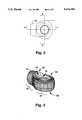
- FIG. 2is a top view of the end connector of an embodiment of the present invention.
- FIG. 3is a perspective view of the end connector of the embodiment of FIG. 2.
- FIG. 4is a vertical cross-sectional view taken along the line 4--4 of the assembly of FIG. 2 showing the captive balled shaft molded within the end connector cavity.
- FIG. 4Ais vertical view of the balled shaft.
- FIG. 5is a vertical cross-sectional view taken along the line 5--5 in FIG. 2.
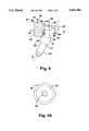
- FIG. 6is a vertical cross-sectional view (similar to FIG. 4) of another embodiment of the assembly of the present invention showing a threaded shaft and threaded end connector.
- FIG. 7is a perspective view of the end of a piston rod with barbs for mounting in the end connector.
- FIG. 8is a perspective view of the end of a piston rod with threads for mounting in the end connector.
- FIG. 9is a cross-sectional view (similar to FIG. 4) of yet another embodiment of the present invention showing a balled shaft assembly with a shaft extending through a special ball and a molded counter bore to accept a threaded or barbed shaft.
- FIG. 10is an isolated cross-section view of the balled shaft component of FIG. 9.
- FIG. 11is an isolated end view of the balled shaft component of FIG. 9.
- two captive ball end connector assembliesare used to mount the ends of a conventional gas spring 14 to a hatch back door 16 and to an adjacent part 18 of the passenger compartment of an automobile. This usage of these assemblies 12 permits relative movement to occur between the gas spring 14 and the door 16 and between the gas spring 14 and the part 18 as the door is opened and closed.
- the captive ball and end connector assembly 12includes a shaft 22 and a connector body 24.
- the end connector 24is molded from a fibre or mica platelet reinforced plastic material, such as a 30% glass filled nylon.
- the shaft 22is formed from metal and has a first end 37 and a second end 39 (FIG. 5).
- a generally spherical ball 26, with a diameter 29,is positioned at the first end 37 of the shaft 22, while the other end 28 is threaded.
- the shaft 22has a central portion 32 that is generally cylindrical in shape and includes a shoulder 34 adjacent to the threaded end 28.
- An inwardly and upwardly sloped neck portion 36extends between ball 26 and the central portion 32.
- the ball 26is not completely spherical in shape.
- the distal end of the ball 26terminates in a flat end surface 38, the plane of which is generally perpendicular to the central longitudinal axis 21 of the shaft 22.
- the end surface 38includes a recess 33 that is adapted to be engaged by a tool (not shown), so that turning the tool causes the shaft 22 to be rotated about its central longitudinal axis 21. This facilitates the threading of the threaded end 28 into or out of a cooperating component threaded for mounting the fitting.
- the end connector 24includes a proximal end 27 for mounting the ball 26, and an enlarged distal end 25.
- a metal retaining washer 42is also used in the assembly 12. This washer 42 encompasses a portion of the spherical surface of the ball 26 so as to provide added support for the mounted ball 26.
- the retaining washer 42might be fabricated from brass, bronze, steel, or sintered material.
- the assembly 12is formed by molding the connector body 24 around the metal ball 26 and washer 42 which are inserted into a connector body mold (not shown) before injection of the plastic connector body material.
- the molding processcan include spraying the ball 26 with a teflon/rust-preventing agent to increase the ease of relative movement of the ball 26 within the connector body 24.
- a zero clearance fitcan be easily achieved and at a lower overall production cost than for other quality connectors.
- quality connectorsneed a ball diameter total tolerance of plus or minus one and one half thousandth (0.0015) of an inch to achieve near zero clearance fit.
- the present invention's technique of molding the connector about the ballallows for a larger ball diameter tolerance of six thousandths (0.006) of an inch to achieve the zero clearance fit.
- the molded connector bodyis formed directly about the ball 26 (and washer 42)
- essentially zero clearanceis achieved between the ball and the ball cavity regardless of the relatively large tolerance on the diameter of the ball portion 26 of the shaft 22.
- Such larger ball toleranceresults in lower production costs for the ball and shaft component 22.
- a zero clearance fiteliminates the problems that accompany connectors having large clearances between the ball and the adjacent ball bearing surface of the connector body.
- the distal end 25 of connector 24forms a connector shank 45 which includes a frustoconical cavity 40, approximately 6 millimeters in diameter.
- the cavity 40has a proximal and a distal end.
- the cavity 40 openingoriginates at the center of the most distal end of connector 24 and extends proximally forward to just before the captured ball 26.
- a relatively thin layer of material 43e.g. thin in relation to the thickness of the walls of the cavity 40 and the connector 24 remains between the most proximal end of cavity 40 and the ball 26.
- Piston rod 50receives the mounting end 51 of a piston rod 50 of the gas spring 14 (FIG. 1).
- Piston rod 50is typically made from metal such as drawn steel rod and includes a plurality of barbs 52 projecting outward on its mounting end 51.
- Piston rod 50also includes a concave end surface 54 which lies in a plane perpendicular to the longitudinal axis 53 of rod 50.
- Piston rod 50might be sonically welded, into cavity 40 of end connector 24.
- the outwardly projecting barbs 52facilitate a secure connection by providing a gripping surface onto which the very viscous material, formed by the welding process, could solidify.
- piston rod 50to end connector 24
- FIGS. 6 and 8another embodiment is shown with the frustoconical cavity 40 being threaded to receive a piston rod 50 which is similarly threaded at its mounting end 51.
- the rod 50thus screws into the cavity 40 to attach the rod 50 to the connector 24.
- the application of an adhesive, such as an anaerobic, to the threads prior to assemblyincreases the strength of the threaded connection.
- the majority of gas springsare designed so that the piston rod is constantly urged to move or extend outwardly from the high pressure, gas containing, cylinder.
- a connector bodywill experience a compressive or possibly a bending load--unless a zero load condition on the connector body is achieved.
- a zero load condition on the connector bodyis promoted if the force vector of the rod 50 intersects the center of the ball 26 on shaft 22.
- a zero load conditionis further facilitated by molding the connector body 24 to have a relative thin film of material 43 between the rod end 54 and the surface of the ball 26.
- the preferred embodimentuses a film layer of material 43 of approximately 0.010 inches. Layer 43 varies with the formation of each connector 24, but generally falls within the range of 0.010 to 0.020 inches.
- a zero load conditionis also facilitated by making the end surface 54 of rod 50 concave in shape.
- the concave end surface 54has a spherical radius approximately equal to that which defines the surface of the spherical ball 26 plus the thickness of the layer 43.
- this thin film 43is best realized by considering the effects of using a relatively thicker layer 43. If instead there is a sizable amount of material between the end of the rod 50 and the surface of the ball 26, several things might happen.
- the body materialmight cold flow due to pressure from the piston rod 50. Cold flow is where a plastic material deforms due to pressure. Cold flow is generally a function of the stress applied to the plastic material, plus several other factors including, for instance, temperature, material composition, material thickness, and the geometry of the material surrounding the stressed volume.
- the thin layer 43allows the concave end 54 of rod 50 to more evenly spread compressive forces from the rod 50 over the thin plastic film surface 43.
- the thin plastic film 43provides a conforming surface compatible with that of the ball 26. This in turn evenly spreads the compressive forces over the projected contact surface of the metal ball 26.
- the end connector 24includes a top surface 61 and a bottom surface 62.
- the top surface 61includes a lip 60 which surrounds the cavity for encompassing the ball 26.
- the lip 60is circular at the proximal end 27 of connector 24.
- the lip 60has an outward flare 64, however, at the distal end 25 of connector 24, and the flare 64 extends outward towards the enlarged distal end 25 and the connector shank 45. This flaring provides a more gradual transition between the relatively thin section of the donut-shaped proximal end 27 and the relatively heavy section that forms the connector shank 45.
- the bottom surface 62 of connector 24has a similar circular lip 42 surrounding the cavity for encompassing the ball 26.
- a flare 48also extends outwards towards the connector shank 45 to provide a more gradual transition between the distal end 25 and the proximal end 27.
- Artisans of moldinggenerally disfavor abrupt changes between molded sections because such changes can lead to problems in gating the mold, and might also create shrinkage problems in the molded part. Therefore, the gradual changes in shape of connector 24 aid in its formation and usability.
- the shaft 22includes shaft ends 76 and 77 which extend outwards from said middle portion 65 along the longitudinal axis 72 of said shaft 22.
- the shaft ends 76 and 77extends outward from both the top surface 61 and the bottom surface 62 of the connector body 24 when the shaft 22 is molded into the connector body 24 with the retaining washer 42.
- the shaft 22includes a hollow cavity 70 extending throughout the shaft 22 along its longitudinal axis 72. This cavity receives an attachment means, such as threaded bolt 74 and an accompanying nut 75 or rivet, for attaching a bracket 80 or similar support member to either side of shaft 22.
- End connector 24is attached to a piston rod 50 (FIGS. 7 and 8) as described previously.
- the cavity 40 in the distal end 25 of end connector 24also extends proximally forward with a thin layer 43 remaining between the cavity 40 and the ball 26.
Landscapes
- Engineering & Computer Science (AREA)
- General Engineering & Computer Science (AREA)
- Mechanical Engineering (AREA)
- Pivots And Pivotal Connections (AREA)
- Connector Housings Or Holding Contact Members (AREA)
- Pens And Brushes (AREA)
- Closures For Containers (AREA)
- Coupling Device And Connection With Printed Circuit (AREA)
Abstract
Description
Claims (11)
Priority Applications (1)
| Application Number | Priority Date | Filing Date | Title |
|---|---|---|---|
| US08/780,713US5676484A (en) | 1995-05-22 | 1997-01-08 | Connector with insert molded captive ball |
Applications Claiming Priority (3)
| Application Number | Priority Date | Filing Date | Title |
|---|---|---|---|
| US44549595A | 1995-05-22 | 1995-05-22 | |
| US69827496A | 1996-08-14 | 1996-08-14 | |
| US08/780,713US5676484A (en) | 1995-05-22 | 1997-01-08 | Connector with insert molded captive ball |
Related Parent Applications (1)
| Application Number | Title | Priority Date | Filing Date |
|---|---|---|---|
| US69827496AContinuation | 1995-05-22 | 1996-08-14 |
Publications (1)
| Publication Number | Publication Date |
|---|---|
| US5676484Atrue US5676484A (en) | 1997-10-14 |
Family
ID=23769132
Family Applications (1)
| Application Number | Title | Priority Date | Filing Date |
|---|---|---|---|
| US08/780,713Expired - Fee RelatedUS5676484A (en) | 1995-05-22 | 1997-01-08 | Connector with insert molded captive ball |
Country Status (8)
| Country | Link |
|---|---|
| US (1) | US5676484A (en) |
| EP (1) | EP0828951B1 (en) |
| JP (1) | JP3234230B2 (en) |
| AT (1) | ATE188019T1 (en) |
| CA (1) | CA2220733C (en) |
| DE (1) | DE69605791T2 (en) |
| ES (1) | ES2140089T3 (en) |
| WO (1) | WO1996037710A1 (en) |
Cited By (24)
| Publication number | Priority date | Publication date | Assignee | Title |
|---|---|---|---|---|
| EP1001179A3 (en)* | 1998-11-11 | 2001-05-30 | Hoerbiger Hydraulik GmbH | Ball-pin for a pivotal connection of two elements |
| WO2001059347A2 (en) | 2000-02-08 | 2001-08-16 | Avm, Inc. | Improved end connector assembly |
| US6354757B1 (en)* | 1997-02-28 | 2002-03-12 | Thyssen Polymer Gmbh | Section connector |
| US20030052491A1 (en)* | 2001-09-17 | 2003-03-20 | Aoyama Seisakusho Co., Ltd. | Resin bracket and opening/shutting mechanism using the same |
| US20040198163A1 (en)* | 2002-11-12 | 2004-10-07 | Wai Fuk Chai Alvin | Frictional joint for toys |
| US20040252922A1 (en)* | 2003-05-15 | 2004-12-16 | Mcintosh Bruce D. | Formable bearings and bearing devices |
| US20050104413A1 (en)* | 2003-11-14 | 2005-05-19 | Bauman Walter D. | High rotation angle for gas spring connection |
| US20060051160A1 (en)* | 2004-09-07 | 2006-03-09 | Sun Prein Co., Ltd. | Ball joint assembly for gas spring |
| US20060061008A1 (en)* | 2004-09-14 | 2006-03-23 | Lee Karner | Mounting assembly for vehicle interior mirror |
| US20060140712A1 (en)* | 2004-12-28 | 2006-06-29 | Sun Prein Co., Ltd. | Gas spring ball joint and method for manufacturing the same |
| US7077717B2 (en) | 2003-05-27 | 2006-07-18 | Mattel, Inc. | Doll with angled and jointed torso |
| US20070253764A1 (en)* | 2006-04-27 | 2007-11-01 | Cedar Mesa Design Company, Llc | Self-locking, quick-releasing, and self-releasing ball-and-socket latch system |
| US20090205167A1 (en)* | 2008-02-14 | 2009-08-20 | Easley James B | Snap Assembly Friction Hinge |
| US7731467B2 (en)* | 1999-07-09 | 2010-06-08 | Profil Verbindungstechnik Gmbh & Co., Kg | Bolt element having a shaft part and a spherical head, component assembly and method for the manufacture of a bolt element |
| US8593521B2 (en) | 2004-04-15 | 2013-11-26 | Magna Electronics Inc. | Imaging system for vehicle |
| US8599001B2 (en) | 1993-02-26 | 2013-12-03 | Magna Electronics Inc. | Vehicular vision system |
| US8636393B2 (en) | 2006-08-11 | 2014-01-28 | Magna Electronics Inc. | Driver assistance system for vehicle |
| US8637801B2 (en) | 1996-03-25 | 2014-01-28 | Magna Electronics Inc. | Driver assistance system for a vehicle |
| US8665079B2 (en) | 2002-05-03 | 2014-03-04 | Magna Electronics Inc. | Vision system for vehicle |
| US8842176B2 (en) | 1996-05-22 | 2014-09-23 | Donnelly Corporation | Automatic vehicle exterior light control |
| US8977008B2 (en) | 2004-09-30 | 2015-03-10 | Donnelly Corporation | Driver assistance system for vehicle |
| US9436880B2 (en) | 1999-08-12 | 2016-09-06 | Magna Electronics Inc. | Vehicle vision system |
| US10144353B2 (en) | 2002-08-21 | 2018-12-04 | Magna Electronics Inc. | Multi-camera vision system for a vehicle |
| US10457209B2 (en) | 2012-02-22 | 2019-10-29 | Magna Electronics Inc. | Vehicle vision system with multi-paned view |
Families Citing this family (4)
| Publication number | Priority date | Publication date | Assignee | Title |
|---|---|---|---|---|
| DE29617843U1 (en)* | 1996-10-14 | 1998-02-12 | Springfix-Befestigungstechnik GmbH, 73084 Salach | Ball-joint connection with effective shielding against external influences |
| WO2002086361A1 (en)* | 2001-04-18 | 2002-10-31 | Fisher Controls International Llc | Pivot actuated sleeve valve |
| JP4540896B2 (en)* | 2001-08-08 | 2010-09-08 | カヤバ工業株式会社 | Ball joint and ball joint molding method |
| WO2003021117A1 (en)* | 2001-09-03 | 2003-03-13 | Aoyama Seisakusho Co., Ltd. | Ball joint assembly and method for manufacturing the same |
Citations (10)
| Publication number | Priority date | Publication date | Assignee | Title |
|---|---|---|---|---|
| US1031982A (en)* | 1907-06-15 | 1912-07-09 | Peninsular Milled Screw Company | Method of forming universal crank-pin couplings. |
| US1868891A (en)* | 1928-10-09 | 1932-07-26 | Faudi Fritz | Coupling |
| US3158528A (en)* | 1961-06-12 | 1964-11-24 | Owens Corning Fiberglass Corp | Siliceous reinforced resins |
| US3177020A (en)* | 1962-04-25 | 1965-04-06 | Champ Items Inc | Pre-lubricated sealed bearings |
| US3176805A (en)* | 1963-03-25 | 1965-04-06 | Newport News S & D Co | Universal boom heel support |
| US3438661A (en)* | 1966-07-08 | 1969-04-15 | Torrington Co | Ball bushing rod end and method of making same |
| US3591669A (en)* | 1968-05-07 | 1971-07-06 | Singer Co | Plastic universal bearings and method of manufacture thereof |
| US4708839A (en)* | 1985-12-30 | 1987-11-24 | Amphenol Corporation | Method of compressively molding articles from resin coated filler materials |
| US5407288A (en)* | 1992-06-30 | 1995-04-18 | Tokai Rubber Industries, Ltd. | Sliding type coupling device having slidable member with gap-filling portion and method of producing the same |
| US5409320A (en)* | 1992-08-26 | 1995-04-25 | Stabilus Gmbh | Ball-and-socket joint and method for the assembly thereof |
Family Cites Families (5)
| Publication number | Priority date | Publication date | Assignee | Title |
|---|---|---|---|---|
| GB1349985A (en)* | 1971-03-09 | 1974-04-10 | Trimay Eng Co Ltd | Method of welding |
| US4118131A (en)* | 1975-04-12 | 1978-10-03 | Stabilus Gmbh | Pneumatic spring |
| US4290181A (en)* | 1979-10-22 | 1981-09-22 | The Bendix Corporation | Ball joint forming method and apparatus therefor |
| JPS60151414A (en)* | 1984-01-17 | 1985-08-09 | Nikkiso Co Ltd | Arm equipped with spherical plain bearing and manufacture thereof |
| JPS6444259A (en)* | 1987-08-10 | 1989-02-16 | Tokai Trw & Co | Production of ball joint |
- 1996
- 1996-04-18ATAT96915328Tpatent/ATE188019T1/ennot_activeIP Right Cessation
- 1996-04-18EPEP96915328Apatent/EP0828951B1/ennot_activeExpired - Lifetime
- 1996-04-18CACA002220733Apatent/CA2220733C/ennot_activeExpired - Lifetime
- 1996-04-18ESES96915328Tpatent/ES2140089T3/ennot_activeExpired - Lifetime
- 1996-04-18DEDE69605791Tpatent/DE69605791T2/ennot_activeExpired - Fee Related
- 1996-04-18WOPCT/US1996/005388patent/WO1996037710A1/enactiveIP Right Grant
- 1996-04-18JPJP53565396Apatent/JP3234230B2/ennot_activeExpired - Fee Related
- 1997
- 1997-01-08USUS08/780,713patent/US5676484A/ennot_activeExpired - Fee Related
Patent Citations (10)
| Publication number | Priority date | Publication date | Assignee | Title |
|---|---|---|---|---|
| US1031982A (en)* | 1907-06-15 | 1912-07-09 | Peninsular Milled Screw Company | Method of forming universal crank-pin couplings. |
| US1868891A (en)* | 1928-10-09 | 1932-07-26 | Faudi Fritz | Coupling |
| US3158528A (en)* | 1961-06-12 | 1964-11-24 | Owens Corning Fiberglass Corp | Siliceous reinforced resins |
| US3177020A (en)* | 1962-04-25 | 1965-04-06 | Champ Items Inc | Pre-lubricated sealed bearings |
| US3176805A (en)* | 1963-03-25 | 1965-04-06 | Newport News S & D Co | Universal boom heel support |
| US3438661A (en)* | 1966-07-08 | 1969-04-15 | Torrington Co | Ball bushing rod end and method of making same |
| US3591669A (en)* | 1968-05-07 | 1971-07-06 | Singer Co | Plastic universal bearings and method of manufacture thereof |
| US4708839A (en)* | 1985-12-30 | 1987-11-24 | Amphenol Corporation | Method of compressively molding articles from resin coated filler materials |
| US5407288A (en)* | 1992-06-30 | 1995-04-18 | Tokai Rubber Industries, Ltd. | Sliding type coupling device having slidable member with gap-filling portion and method of producing the same |
| US5409320A (en)* | 1992-08-26 | 1995-04-25 | Stabilus Gmbh | Ball-and-socket joint and method for the assembly thereof |
Cited By (80)
| Publication number | Priority date | Publication date | Assignee | Title |
|---|---|---|---|---|
| US8917169B2 (en) | 1993-02-26 | 2014-12-23 | Magna Electronics Inc. | Vehicular vision system |
| US8599001B2 (en) | 1993-02-26 | 2013-12-03 | Magna Electronics Inc. | Vehicular vision system |
| US8637801B2 (en) | 1996-03-25 | 2014-01-28 | Magna Electronics Inc. | Driver assistance system for a vehicle |
| US8993951B2 (en) | 1996-03-25 | 2015-03-31 | Magna Electronics Inc. | Driver assistance system for a vehicle |
| US8842176B2 (en) | 1996-05-22 | 2014-09-23 | Donnelly Corporation | Automatic vehicle exterior light control |
| US6354757B1 (en)* | 1997-02-28 | 2002-03-12 | Thyssen Polymer Gmbh | Section connector |
| EP1001179A3 (en)* | 1998-11-11 | 2001-05-30 | Hoerbiger Hydraulik GmbH | Ball-pin for a pivotal connection of two elements |
| US7731467B2 (en)* | 1999-07-09 | 2010-06-08 | Profil Verbindungstechnik Gmbh & Co., Kg | Bolt element having a shaft part and a spherical head, component assembly and method for the manufacture of a bolt element |
| US9436880B2 (en) | 1999-08-12 | 2016-09-06 | Magna Electronics Inc. | Vehicle vision system |
| WO2001059347A2 (en) | 2000-02-08 | 2001-08-16 | Avm, Inc. | Improved end connector assembly |
| US20030052491A1 (en)* | 2001-09-17 | 2003-03-20 | Aoyama Seisakusho Co., Ltd. | Resin bracket and opening/shutting mechanism using the same |
| US6869129B2 (en)* | 2001-09-17 | 2005-03-22 | Aoyama Seisakusho Co., Ltd. | Resin bracket and opening/shutting mechanism using the same |
| US9171217B2 (en) | 2002-05-03 | 2015-10-27 | Magna Electronics Inc. | Vision system for vehicle |
| US10118618B2 (en) | 2002-05-03 | 2018-11-06 | Magna Electronics Inc. | Vehicular control system using cameras and radar sensor |
| US10351135B2 (en) | 2002-05-03 | 2019-07-16 | Magna Electronics Inc. | Vehicular control system using cameras and radar sensor |
| US8665079B2 (en) | 2002-05-03 | 2014-03-04 | Magna Electronics Inc. | Vision system for vehicle |
| US11203340B2 (en) | 2002-05-03 | 2021-12-21 | Magna Electronics Inc. | Vehicular vision system using side-viewing camera |
| US9555803B2 (en) | 2002-05-03 | 2017-01-31 | Magna Electronics Inc. | Driver assistance system for vehicle |
| US9643605B2 (en) | 2002-05-03 | 2017-05-09 | Magna Electronics Inc. | Vision system for vehicle |
| US9834216B2 (en) | 2002-05-03 | 2017-12-05 | Magna Electronics Inc. | Vehicular control system using cameras and radar sensor |
| US10683008B2 (en) | 2002-05-03 | 2020-06-16 | Magna Electronics Inc. | Vehicular driving assist system using forward-viewing camera |
| US9183749B2 (en) | 2002-08-21 | 2015-11-10 | Magna Electronics Inc. | Rear vision system for a vehicle |
| US10144353B2 (en) | 2002-08-21 | 2018-12-04 | Magna Electronics Inc. | Multi-camera vision system for a vehicle |
| US9796331B2 (en) | 2002-08-21 | 2017-10-24 | Magna Electronics Inc. | Multi-camera vision system for a vehicle |
| US9440586B2 (en) | 2002-08-21 | 2016-09-13 | Magna Electronics Inc. | Multi-camera vision system for a vehicle |
| US7021989B2 (en) | 2002-11-12 | 2006-04-04 | Mattel, Inc. | Frictional joint for toys |
| US20040198163A1 (en)* | 2002-11-12 | 2004-10-07 | Wai Fuk Chai Alvin | Frictional joint for toys |
| US20060228985A1 (en)* | 2002-11-12 | 2006-10-12 | Wai Fuk C A | Frictional joint for toys |
| US7566256B2 (en) | 2002-11-12 | 2009-07-28 | Mattel, Inc. | Frictional joint for toys |
| US7150563B2 (en) | 2003-05-15 | 2006-12-19 | Phd, Inc. | Formable bearings and bearing devices |
| US20040252922A1 (en)* | 2003-05-15 | 2004-12-16 | Mcintosh Bruce D. | Formable bearings and bearing devices |
| US7077717B2 (en) | 2003-05-27 | 2006-07-18 | Mattel, Inc. | Doll with angled and jointed torso |
| US7172237B2 (en) | 2003-11-14 | 2007-02-06 | Avm Industries | High rotation angle for gas spring connection |
| US20050104413A1 (en)* | 2003-11-14 | 2005-05-19 | Bauman Walter D. | High rotation angle for gas spring connection |
| US9191634B2 (en) | 2004-04-15 | 2015-11-17 | Magna Electronics Inc. | Vision system for vehicle |
| US10187615B1 (en) | 2004-04-15 | 2019-01-22 | Magna Electronics Inc. | Vehicular control system |
| US8593521B2 (en) | 2004-04-15 | 2013-11-26 | Magna Electronics Inc. | Imaging system for vehicle |
| US10110860B1 (en) | 2004-04-15 | 2018-10-23 | Magna Electronics Inc. | Vehicular control system |
| US11503253B2 (en) | 2004-04-15 | 2022-11-15 | Magna Electronics Inc. | Vehicular control system with traffic lane detection |
| US9428192B2 (en) | 2004-04-15 | 2016-08-30 | Magna Electronics Inc. | Vision system for vehicle |
| US11847836B2 (en) | 2004-04-15 | 2023-12-19 | Magna Electronics Inc. | Vehicular control system with road curvature determination |
| US10462426B2 (en) | 2004-04-15 | 2019-10-29 | Magna Electronics Inc. | Vehicular control system |
| US10015452B1 (en) | 2004-04-15 | 2018-07-03 | Magna Electronics Inc. | Vehicular control system |
| US9008369B2 (en) | 2004-04-15 | 2015-04-14 | Magna Electronics Inc. | Vision system for vehicle |
| US9609289B2 (en) | 2004-04-15 | 2017-03-28 | Magna Electronics Inc. | Vision system for vehicle |
| US10306190B1 (en) | 2004-04-15 | 2019-05-28 | Magna Electronics Inc. | Vehicular control system |
| US9736435B2 (en) | 2004-04-15 | 2017-08-15 | Magna Electronics Inc. | Vision system for vehicle |
| US10735695B2 (en) | 2004-04-15 | 2020-08-04 | Magna Electronics Inc. | Vehicular control system with traffic lane detection |
| US8818042B2 (en) | 2004-04-15 | 2014-08-26 | Magna Electronics Inc. | Driver assistance system for vehicle |
| US9948904B2 (en) | 2004-04-15 | 2018-04-17 | Magna Electronics Inc. | Vision system for vehicle |
| US20060051160A1 (en)* | 2004-09-07 | 2006-03-09 | Sun Prein Co., Ltd. | Ball joint assembly for gas spring |
| US10556542B2 (en) | 2004-09-14 | 2020-02-11 | Magna Electronics Inc. | Rear backup system for a vehicle |
| US10703274B2 (en) | 2004-09-14 | 2020-07-07 | Magna Electronics Inc. | Vehicular multi-camera vision system including rear backup camera |
| US20060061008A1 (en)* | 2004-09-14 | 2006-03-23 | Lee Karner | Mounting assembly for vehicle interior mirror |
| US8976247B1 (en) | 2004-09-14 | 2015-03-10 | Magna Electronics Inc. | Rear vision system for a vehicle |
| US10800331B1 (en) | 2004-09-14 | 2020-10-13 | Magna Electronics Inc. | Vehicular vision system including rear backup camera |
| US8896700B2 (en) | 2004-09-14 | 2014-11-25 | Magna Electronics Inc. | Rear vision system for a vehicle |
| US10308180B2 (en) | 2004-09-14 | 2019-06-04 | Magna Electronics Inc. | Rear backup system for a vehicle |
| US8743203B2 (en) | 2004-09-14 | 2014-06-03 | Magna Electronics Inc. | Rear vision system for a vehicle |
| US11813987B2 (en) | 2004-09-14 | 2023-11-14 | Magna Electronics Inc. | Vehicular trailer hitching assist system |
| US11577646B2 (en) | 2004-09-14 | 2023-02-14 | Magna Electronics Inc. | Vehicular trailer hitching assist system |
| US11155210B2 (en) | 2004-09-14 | 2021-10-26 | Magna Electronics Inc. | Vehicular driving assist system including multiple cameras and radar sensor |
| US8977008B2 (en) | 2004-09-30 | 2015-03-10 | Donnelly Corporation | Driver assistance system for vehicle |
| US10623704B2 (en) | 2004-09-30 | 2020-04-14 | Donnelly Corporation | Driver assistance system for vehicle |
| US20060140712A1 (en)* | 2004-12-28 | 2006-06-29 | Sun Prein Co., Ltd. | Gas spring ball joint and method for manufacturing the same |
| US7762735B2 (en)* | 2006-04-27 | 2010-07-27 | Cedar Mesa Design Company, Llc | Self-locking, quick-releasing, and self-releasing ball-and-socket latch system |
| US20070253764A1 (en)* | 2006-04-27 | 2007-11-01 | Cedar Mesa Design Company, Llc | Self-locking, quick-releasing, and self-releasing ball-and-socket latch system |
| US10787116B2 (en) | 2006-08-11 | 2020-09-29 | Magna Electronics Inc. | Adaptive forward lighting system for vehicle comprising a control that adjusts the headlamp beam in response to processing of image data captured by a camera |
| US11148583B2 (en) | 2006-08-11 | 2021-10-19 | Magna Electronics Inc. | Vehicular forward viewing image capture system |
| US10071676B2 (en) | 2006-08-11 | 2018-09-11 | Magna Electronics Inc. | Vision system for vehicle |
| US11396257B2 (en) | 2006-08-11 | 2022-07-26 | Magna Electronics Inc. | Vehicular forward viewing image capture system |
| US8636393B2 (en) | 2006-08-11 | 2014-01-28 | Magna Electronics Inc. | Driver assistance system for vehicle |
| US11623559B2 (en) | 2006-08-11 | 2023-04-11 | Magna Electronics Inc. | Vehicular forward viewing image capture system |
| US9440535B2 (en) | 2006-08-11 | 2016-09-13 | Magna Electronics Inc. | Vision system for vehicle |
| US11951900B2 (en) | 2006-08-11 | 2024-04-09 | Magna Electronics Inc. | Vehicular forward viewing image capture system |
| US20090205167A1 (en)* | 2008-02-14 | 2009-08-20 | Easley James B | Snap Assembly Friction Hinge |
| US7958599B2 (en) | 2008-02-14 | 2011-06-14 | Easley James B | Snap assembly friction hinge |
| US11007937B2 (en) | 2012-02-22 | 2021-05-18 | Magna Electronics Inc. | Vehicular display system with multi-paned image display |
| US11607995B2 (en) | 2012-02-22 | 2023-03-21 | Magna Electronics Inc. | Vehicular display system with multi-paned image display |
| US10457209B2 (en) | 2012-02-22 | 2019-10-29 | Magna Electronics Inc. | Vehicle vision system with multi-paned view |
Also Published As
| Publication number | Publication date |
|---|---|
| CA2220733A1 (en) | 1996-11-28 |
| EP0828951A1 (en) | 1998-03-18 |
| ES2140089T3 (en) | 2000-02-16 |
| JP2000514158A (en) | 2000-10-24 |
| DE69605791D1 (en) | 2000-01-27 |
| EP0828951A4 (en) | 1998-09-02 |
| JP3234230B2 (en) | 2001-12-04 |
| WO1996037710A1 (en) | 1996-11-28 |
| ATE188019T1 (en) | 2000-01-15 |
| EP0828951B1 (en) | 1999-12-22 |
| CA2220733C (en) | 2004-02-24 |
| DE69605791T2 (en) | 2000-05-11 |
Similar Documents
| Publication | Publication Date | Title |
|---|---|---|
| US5676484A (en) | Connector with insert molded captive ball | |
| US3279834A (en) | Ball joint seal construction | |
| EP0779442B1 (en) | Joint assembly | |
| US3389927A (en) | Joint assembly | |
| US6213675B1 (en) | Axial joint | |
| JP2004523407A (en) | Blocking ball joint for steering and suspension | |
| GB2268971A (en) | Captive ball joint end connector assembly | |
| US6113303A (en) | Ball pin of a universal joint for motor vehicles | |
| CN112128223B (en) | Ball joint with multi-piece ball stud | |
| CA3055180A1 (en) | Socket assembly | |
| CN111819367A (en) | Improved socket assembly and method of making same | |
| CN111868396B (en) | Improved socket assembly and method of making same | |
| US4537524A (en) | Ball and socket joint | |
| US20040265046A1 (en) | Ball-and-socket joint | |
| JPS6346286B2 (en) | ||
| US5595452A (en) | Link assembly and bushing therefor | |
| US20040037622A1 (en) | Ceramic ball-and-socket joint | |
| CN210623383U (en) | Ball seat assembly | |
| US11859657B2 (en) | Socket assembly with a retention device | |
| US12038039B2 (en) | Socket assembly with a coated washer | |
| US6594858B1 (en) | Coupling device for joining a door stop to the hinge of door of a motor vehicle | |
| US20020051678A1 (en) | Flanged ball pin and method for manufacturing thereof | |
| GB2233385A (en) | Ball and socket joint | |
| US3343856A (en) | Ball joint construction for motor vehicle suspension and steering systems | |
| US11274692B2 (en) | Self-tapping compression limiter |
Legal Events
| Date | Code | Title | Description |
|---|---|---|---|
| FPAY | Fee payment | Year of fee payment:4 | |
| FEPP | Fee payment procedure | Free format text:PAYOR NUMBER ASSIGNED (ORIGINAL EVENT CODE: ASPN); ENTITY STATUS OF PATENT OWNER: LARGE ENTITY | |
| FPAY | Fee payment | Year of fee payment:8 | |
| AS | Assignment | Owner name:ARVINMERITOR TECHNOLOGY, LLC, MICHIGAN Free format text:ASSIGNMENT OF ASSIGNORS INTEREST;ASSIGNOR:AVM, INC.;REEL/FRAME:016651/0587 Effective date:20050614 | |
| AS | Assignment | Owner name:AVM INDUSTRIES, LLC, OHIO Free format text:ASSIGNMENT OF ASSIGNORS INTEREST;ASSIGNOR:ARVINMERITOR TECHNOLOGY LLC;REEL/FRAME:018171/0739 Effective date:20060725 | |
| AS | Assignment | Owner name:PNC BANK, NATIONAL ASSOCIATION, PENNSYLVANIA Free format text:SECURITY AGREEMENT;ASSIGNOR:AVM INDUSTRIES, LLC;REEL/FRAME:018224/0236 Effective date:20060725 | |
| AS | Assignment | Owner name:PNC BANK, NATIONAL ASSOCIATION, OHIO Free format text:SECURITY AGREEMENT;ASSIGNOR:AVM INDUSTRIES, LLC;REEL/FRAME:020385/0300 Effective date:20071231 | |
| REMI | Maintenance fee reminder mailed | ||
| LAPS | Lapse for failure to pay maintenance fees | ||
| STCH | Information on status: patent discontinuation | Free format text:PATENT EXPIRED DUE TO NONPAYMENT OF MAINTENANCE FEES UNDER 37 CFR 1.362 | |
| FP | Lapsed due to failure to pay maintenance fee | Effective date:20091014 | |
| AS | Assignment | Owner name:JP MORGAN CHASE BANK, N.A., OHIO Free format text:SECURITY AGREEMENT;ASSIGNORS:AVM INDUSTRIES, LLC;CARTER FUEL SYSTEMS, LLC;REEL/FRAME:031393/0769 Effective date:20130923 | |
| AS | Assignment | Owner name:MWV PINNACLE CAPTIAL FUND, L.P., OHIO Free format text:SECURITY AGREEMENT;ASSIGNOR:AVM INDUSTRIES, LLC;REEL/FRAME:031436/0382 Effective date:20130923 | |
| AS | Assignment | Owner name:AVM INDUSTRIES , LLC, SOUTH CAROLINA Free format text:RELEASE BY SECURED PARTY;ASSIGNOR:PNC BANK, NATIONAL ASSOCIATION;REEL/FRAME:031506/0018 Effective date:20130917 | |
| AS | Assignment | Owner name:AVM INDUSTRIES, LLC, SOUTH CAROLINA Free format text:RELEASE OF SECURITY INTEREST IN PATENTS AND TRADEMARKS;ASSIGNOR:MWV PINNACLE CAPITAL FUND, L.P.;REEL/FRAME:033897/0176 Effective date:20140930 | |
| AS | Assignment | Owner name:AVM INDUSTRIES, LLC, SOUTH CAROLINA Free format text:RELEASE BY SECURED PARTY;ASSIGNOR:JPMORGAN CHASE BANK, N.A.;REEL/FRAME:033974/0133 Effective date:20140930 Owner name:CARTER FUEL SYSTEMS, LLC, INDIANA Free format text:RELEASE BY SECURED PARTY;ASSIGNOR:JPMORGAN CHASE BANK, N.A.;REEL/FRAME:033974/0133 Effective date:20140930 |