US5676278A - Water dispensing feed tube with improved flow - Google Patents
Water dispensing feed tube with improved flowDownload PDFInfo
- Publication number
- US5676278A US5676278AUS08/430,438US43043895AUS5676278AUS 5676278 AUS5676278 AUS 5676278AUS 43043895 AUS43043895 AUS 43043895AUS 5676278 AUS5676278 AUS 5676278A
- Authority
- US
- United States
- Prior art keywords
- feed tube
- bottle
- water
- tip end
- inverted
- Prior art date
- Legal status (The legal status is an assumption and is not a legal conclusion. Google has not performed a legal analysis and makes no representation as to the accuracy of the status listed.)
- Expired - Lifetime
Links
- XLYOFNOQVPJJNP-UHFFFAOYSA-NwaterSubstancesOXLYOFNOQVPJJNP-UHFFFAOYSA-N0.000titleclaimsabstractdescription47
- 238000007789sealingMethods0.000claimsabstractdescription13
- 230000000630rising effectEffects0.000claimsabstractdescription4
- 235000012206bottled waterNutrition0.000description10
- 238000000034methodMethods0.000description2
- 230000002093peripheral effectEffects0.000description2
- 230000000717retained effectEffects0.000description2
- 239000011324beadSubstances0.000description1
- 239000011521glassSubstances0.000description1
- 239000007788liquidSubstances0.000description1
- 239000000463materialSubstances0.000description1
- 238000012986modificationMethods0.000description1
- 230000004048modificationEffects0.000description1
- 230000000149penetrating effectEffects0.000description1
- 230000001681protective effectEffects0.000description1
Images

Classifications
- B—PERFORMING OPERATIONS; TRANSPORTING
- B67—OPENING, CLOSING OR CLEANING BOTTLES, JARS OR SIMILAR CONTAINERS; LIQUID HANDLING
- B67D—DISPENSING, DELIVERING OR TRANSFERRING LIQUIDS, NOT OTHERWISE PROVIDED FOR
- B67D3/00—Apparatus or devices for controlling flow of liquids under gravity from storage containers for dispensing purposes
- B67D3/0029—Apparatus or devices for controlling flow of liquids under gravity from storage containers for dispensing purposes provided with holders for bottles or similar containers
- B67D3/0032—Apparatus or devices for controlling flow of liquids under gravity from storage containers for dispensing purposes provided with holders for bottles or similar containers the bottle or container being held upside down and provided with a closure, e.g. a cap, adapted to cooperate with a feed tube
Definitions
- the present inventionrelates generally to bottled water dispensers and more particularly concerns a feed tube having improved flow characteristics for use with such bottled water dispensers.
- Bottled water dispensershave been commercially available for many years. Typically, such dispensers are designed for use with large bottles, for example on the order of five gallons or so.
- the bottlesare filled with pure natural spring water or water that has been subjected to a commercial purifying process and then delivered to where the bottled water dispenser is located.
- the filled bottleis then uncapped, inverted and placed on the dispenser housing so that water flows from the bottle into a reservoir located in the dispenser housing.
- As the water flows out from the mouth of the bottleit causes a partial vacuum in the bottle and replacement air is drawn up through the mouth into the bottle.
- the water in the reservoirrises to the level of the bottle mouth, flow stops because no more air can enter the bottle to displace the water flowing out.
- the dispenseris provided with an upstanding hollow feed tube that is disposed and dimensioned to penetrate into and through an axial recess formed centrally in the bottle cap.
- the capmay be of one-piece design with a hollow plug portion integrally attached to the inner end of the cap recess as is shown in Baker et al. U.S. Pat. No. 5,121,778 or the cap may be of two-piece design with the plug portion disposed telescopically within the inner end of the cap recess as is shown in U.S. Pat. No. 5,232,125 to Adams.
- bubble diverting meansare disposed within the tip end of the feed tube for intercepting the rising bubbles of replacement air and diverting the bubbles outwardly through one of the radial openings in the feed tube tip while another radial opening in the feed tube tip permits the free inflow of water from the bottle into the feed tube for discharge into the reservoir below.
- the bubble diverting meansis in the form of an inverted conical member with a flared skirt leading out to the upper edge of the substantially rectangular shaped radial openings.
- FIG. 1is a perspective view of a bottled water dispensing unit which incorporates the feed tube having improved flow characteristics of the present invention
- FIG. 2is a partial vertical cross section of the top portion of the dispensing unit of FIG. 1 showing the upstanding feed tube of the present invention mounted above the water receiving reservoir within the dispensing unit;
- FIG. 3is a partial cross section, similar to FIG. 2, with an inverted water bottle mounted on the dispensing unit and showing the downward flow of water and upward flow of replacement air bubbles through the hollow feed tube of the present invention;
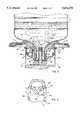
- FIG. 4is an enlarged vertical cross section of the tip end of the hollow feed tube showing the internal conical diverter for directing the flow of replacement air bubbles out through the radial openings in the feed tube tip.
- FIG. 1a bottled water dispensing unit indicated generally at 10 supporting an inverted water bottle 11.
- the dispensing unit 10has the general shape of an upstanding rectangular box including side panels 12 and 13, a front panel 14 and a top panel 15.
- the front panel 14includes a recessed cavity 16 with a drip pan 17 in the bottom thereof and one or more faucet valve operating levers 18 disposed along the top edge of the cavity 16.
- the dispenser unit 10is assembled of readily removable side panels 12 and 13 and demountable frame components such as disclosed in copending U.S. application Ser. No. 08/139,469, filed Oct. 20, 1993, which is hereby incorporated herein by reference.
- the dispenser unit 10also preferably houses readily a removable reservoir, hot tank and valving components such as disclosed in U.S. Pat. No. 5,493,873, which is hereby incorporated herein by reference.
- the dispensing unit 10includes a "no spill" type dispensing adapter 20 including a generally bowl-shaped mounting adapter 21 having an upper peripheral flange 22 supported on the outwardly flared upper end 23 of the water receiving reservoir 24 located within the dispenser unit 10.
- a hollow upstanding feed tube 25is disposed substantially centrally in the mounting adapter 21 and as will be explained in greater detail hereinafter is dimensioned to penetrate into and sealingly engage an inwardly directed axial recess in the water bottle cap.
- the upper end of the reservoir 24is closed and sealed by a circumferential gasket member 26 which is carried on an intermediate side wall portion of the mounting adapter 21.
- a hollow boss 27 in the adapter 21defines an air inlet opening through which replacement air may be communicated by a tube 28 from an air filter unit 29 into the space above the water in the reservoir 24.
- a generally funnel-shaped entry cone 32is disposed with its lower end engaging the mounting adapter 21 and its upper end supported by the top panel 15.
- the top panel 15is supported by a top frame piece 30 as disclosed in the aforementioned application Ser. No. 08/139,469.
- the mounting adapter 21also includes a pair of flanged arms or brackets 31 which engage and are supported in recesses formed in the upper surface of the top frame piece 30 so as to suspend the mounting adapter 21 above the reservoir 24.
- an inverted water bottle 11is shown mounted and supported by the dispensing unit 10 so as to discharge water into the reservoir 24.
- the bottle 11may be formed of glass or plastic material and typically has a capacity of five gallons or so.
- the bottle 11is of conventional design with a generally cylindrical body merging into a downwardly and inwardly sloping shoulder and a depending neck which terminates in a mouth or discharge opening, when inverted as shown in FIG. 3.
- the mouth of the bottleis normally closed and sealed by a plastic cap 35 having a skirt portion and a peripheral seal which engages an external sealing bead formed on the bottle neck adjacent the mouth.
- the bottle cap 35is formed with an axially inwardly extending central recess 36 which is normally closed by removable sealing means such as a sealing plug 37.
- a sealing plug 37may be integrally formed as an inward extension of the recess 36 such as disclosed in U.S. Pat. No. 5,121,778 or the cap may be of two-piece design with the sealing plug portion 37 disposed within the inner end of the cap recess as is shown in U.S. Pat. No. 5,232,125.
- the feed tubepenetrates into the cap recess 36 and engages the sealing plug portion 37 and separates it from the inner end of the cap recess 36. This exposes radial openings 38 formed in the tip end 39 of the feed tube and exposes these openings to water in the bottle.
- the tip end 39 of the feed tubeincludes an annular groove 40 which is adapted to receive and retain an inwardly directed annular gripping lip formed on the inside of the sealing plug portion 37.
- the flow of replacement air up through the feed tube 25 and the discharge of water down through the feed tube 25is substantially improved by providing bubble intercepting and diverting means 45 inside the tip end 39 of the feed tube 25.
- the bubble intercepting and diverting means 45is substantially in the form of an inverted cone disposed in the tip end 39 of the hollow feed tube 25 adjacent the radial openings 38.
- the base of the conical bubble diverting means 45is flared outwardly and is disposed to lead outwardly at the upper edges of the radial openings which are preferably generally rectangular in shape.
- the conical bubble intercepting and diverter means 45 of the present inventionsubstantially increases the flow of water through the feed tube 25.
- the flow rates from a bottled water dispenser into a user's containerwere the following for one dispenser with a regular feed tube (without conical dispenser) and another dispenser with the same size feed tube including the conical dispenser of the present invention.
Landscapes
- Engineering & Computer Science (AREA)
- Mechanical Engineering (AREA)
- Closures For Containers (AREA)
Abstract
Description
______________________________________ Fill Time in Seconds Cup Size Conventional Feed Tube Feed Tue with Diverter ______________________________________ 6 oz. 5.0 seconds 4.6seconds 16 oz. 6.7 seconds 5.7seconds 32 oz. 48.5 seconds 26.4 seconds 60 oz. 95.8 seconds 54.5 seconds ______________________________________
Claims (4)
Priority Applications (3)
| Application Number | Priority Date | Filing Date | Title |
|---|---|---|---|
| US08/430,438US5676278A (en) | 1995-04-28 | 1995-04-28 | Water dispensing feed tube with improved flow |
| PCT/US1996/005614WO1996033945A1 (en) | 1995-04-28 | 1996-04-22 | Water dispensing feed tube with improved flow |
| AU55661/96AAU5566196A (en) | 1995-04-28 | 1996-04-22 | Water dispensing feed tube with improved flow |
Applications Claiming Priority (1)
| Application Number | Priority Date | Filing Date | Title |
|---|---|---|---|
| US08/430,438US5676278A (en) | 1995-04-28 | 1995-04-28 | Water dispensing feed tube with improved flow |
Publications (1)
| Publication Number | Publication Date |
|---|---|
| US5676278Atrue US5676278A (en) | 1997-10-14 |
Family
ID=23707569
Family Applications (1)
| Application Number | Title | Priority Date | Filing Date |
|---|---|---|---|
| US08/430,438Expired - LifetimeUS5676278A (en) | 1995-04-28 | 1995-04-28 | Water dispensing feed tube with improved flow |
Country Status (3)
| Country | Link |
|---|---|
| US (1) | US5676278A (en) |
| AU (1) | AU5566196A (en) |
| WO (1) | WO1996033945A1 (en) |
Cited By (43)
| Publication number | Priority date | Publication date | Assignee | Title |
|---|---|---|---|---|
| USD419370S (en)* | 1998-10-02 | 2000-01-25 | Oasis Corporation | Cap for a water bottle |
| USD426746S (en) | 1999-08-13 | 2000-06-20 | Oasis Corporation | Feed tube adapter for a bottled water cooler |
| USD429111S (en)* | 1998-10-02 | 2000-08-08 | Oasis Corporation | Feed tube adapter for a bottled water cooler |
| US6123232A (en)* | 1993-10-20 | 2000-09-26 | Elkay Manufacturing Company | Liquid dispensing device and hygienic adapter therefor |
| USD448974S1 (en) | 2001-02-08 | 2001-10-09 | Oasis Corporation | Feed tube adapter for a bottled water cooler |
| US20020092813A1 (en)* | 2000-02-18 | 2002-07-18 | Radford Thomas K. | Method and apparatus for water purification |
| US6485644B2 (en) | 1998-06-09 | 2002-11-26 | Henry Alan Bowler | Liquid dispenser with closed gravity filter and air breathing system |
| US20020195141A1 (en)* | 2001-06-26 | 2002-12-26 | Ruschke Rick R. | Check valve and filter assembly incorporating such valve, especially for water cooler assemblies |
| WO2003035540A3 (en)* | 2001-10-23 | 2003-06-05 | Oasis Corp | Bottled water station |
| WO2003070587A1 (en)* | 2002-02-21 | 2003-08-28 | Shao, Wen-Bin | An improved cap structure for water bottle |
| US6619511B2 (en) | 2001-02-08 | 2003-09-16 | Oasis Corporation | Feed tube adapter for a bottled water cooler |
| US6648180B2 (en) | 2001-11-19 | 2003-11-18 | Clover Company Ltd. | Duplex stopper-type water dispensing and water bottle supporting apparatus |
| US20040045206A1 (en)* | 2002-09-11 | 2004-03-11 | James Witham | Advertising method for fixed bottle bottled water dispenser |
| US20040045205A1 (en)* | 2002-09-11 | 2004-03-11 | James Witham | Advertising method for changeable bottle bottled water dispenser |
| US6772807B1 (en) | 2003-06-13 | 2004-08-10 | Chang Kuei Tang | Sealing structure of drinking water tank |
| US20040231720A1 (en)* | 2001-06-26 | 2004-11-25 | Filtertek Inc. | Check valve and filter assembly incorporating such valve, especially for water cooler assemblies |
| US20040251277A1 (en)* | 2003-06-13 | 2004-12-16 | Tang Chang Kuei | Water inlet and venting pipe of water dispenser |
| US20040261865A1 (en)* | 2003-06-24 | 2004-12-30 | Tang Chang Kuei | Outlet valve structure for water dispenser |
| US20050000878A1 (en)* | 2003-07-03 | 2005-01-06 | Tang Chang Kuei | Filtering apparatus of water dispenser |
| US20050006405A1 (en)* | 2003-07-08 | 2005-01-13 | Tang Chang Kuei | Bottled type water dispenser |
| EP1506935A1 (en)* | 2003-08-11 | 2005-02-16 | Young One Corporation | Bottled water dispenser with air inlet valve |
| WO2005017424A3 (en)* | 2003-08-06 | 2005-03-31 | Posidon Mfg Corp | Cooler for water or other beverage |
| US20050109800A1 (en)* | 2003-11-24 | 2005-05-26 | Cactrus Drink Systems Inc. | Bottle cap |
| US20050224133A1 (en)* | 2004-12-29 | 2005-10-13 | George Yui | Receptacle assembly for bottled water dispenser |
| WO2007029901A1 (en)* | 2005-09-05 | 2007-03-15 | Barflex Corporation | Liquid dispensing apparatus capable of regulating discharged amount of liquid |
| US20070062972A1 (en)* | 2005-09-19 | 2007-03-22 | Feldman Marjorie E | Beverage dispensing system and method |
| US20070267100A1 (en)* | 2006-05-08 | 2007-11-22 | Spear Gregory N | Bottle Cap and Method of Use With a Liquid Dispensing Apparatus and System |
| US20080053564A1 (en)* | 2006-08-30 | 2008-03-06 | Mtn Products, Inc. | Bottom Load Water Cooler |
| US20080054017A1 (en)* | 2006-08-30 | 2008-03-06 | Mtn Products, Inc. | Liquid Dispensing Apparatus and System |
| USD582194S1 (en) | 2007-11-13 | 2008-12-09 | Mtn Products, Inc. | Water cooler |
| US20090277535A1 (en)* | 2006-08-30 | 2009-11-12 | Mtn Products, Inc. | Bottom load water cooler |
| USD608129S1 (en) | 2008-03-10 | 2010-01-19 | MTN Products, Inc | Water cooler |
| USD617132S1 (en) | 2009-09-08 | 2010-06-08 | Mtn Products, Inc. | Water cooler |
| USD623885S1 (en) | 2009-06-18 | 2010-09-21 | Mtn Products, Inc. | Water cooler |
| US20110056981A1 (en)* | 2009-09-09 | 2011-03-10 | Mtn Products, Inc. | Energy saving baffle for water cooler |
| USD642849S1 (en) | 2010-04-28 | 2011-08-09 | MTN Products, Inc | Water cooler |
| USD643239S1 (en) | 2010-04-28 | 2011-08-16 | MTN Products, Inc | Water cooler |
| USD677509S1 (en) | 2011-09-23 | 2013-03-12 | MTN Products, Inc | Water cooler |
| USD688079S1 (en) | 2012-02-21 | 2013-08-20 | Chun Yen Wang | Combination water dispenser and beverage brewer |
| US20130306530A1 (en)* | 2011-02-28 | 2013-11-21 | Uchimura Co., Ltd. | Drinking water server |
| US20150068983A1 (en)* | 2012-04-10 | 2015-03-12 | Scandinavian Innovation Group Oy | Disinfection device for water dispenser |
| USD836440S1 (en) | 2016-07-22 | 2018-12-25 | Silgan White Cap LLC | Closure |
| US11337562B2 (en)* | 2020-03-27 | 2022-05-24 | Déric RUSSIER | Device for dispensing gel or liquid |
Families Citing this family (1)
| Publication number | Priority date | Publication date | Assignee | Title |
|---|---|---|---|---|
| BR9805484A (en)* | 1998-11-24 | 2000-06-06 | Anselmo Luiz De Siqueira Campe | Hygienic protector, with flush valve, for mineral water canisters |
Citations (15)
| Publication number | Priority date | Publication date | Assignee | Title |
|---|---|---|---|---|
| US1228836A (en)* | 1915-12-02 | 1917-06-05 | Safety First Filter Company Inc | Water-cooler. |
| US1319376A (en)* | 1919-10-21 | Planooraph co | ||
| US2057238A (en)* | 1934-11-05 | 1936-10-13 | Philip P Krug | Liquid-dispensing apparatus |
| US3892235A (en)* | 1971-07-27 | 1975-07-01 | Respiratory Care | Multi-use inhalation therapy apparatus |
| US4597423A (en)* | 1985-03-26 | 1986-07-01 | Chenot Gary D | Device for opening bottled water containers |
| USRE32354E (en)* | 1980-07-21 | 1987-02-17 | Scholle Corporation | Container for holding and dispensing fluid |
| US4682187A (en)* | 1984-11-08 | 1987-07-21 | Martner John G | Ink jet method and apparatus utilizing grandular or hot melt ink |
| US4793514A (en)* | 1987-05-14 | 1988-12-27 | Sheets Kerney T | Cap for inverted water bottle |
| US4846236A (en)* | 1987-07-06 | 1989-07-11 | Deruntz William R | Bottled water dispenser insert |
| US4874023A (en)* | 1988-09-30 | 1989-10-17 | Liqui-Box Corporation | Decap dispensing system for water cooler bottles |
| US4991635A (en)* | 1988-09-30 | 1991-02-12 | Liqui-Box Corporation | Decap dispensing system for water cooler bottles |
| US5121778A (en)* | 1988-10-14 | 1992-06-16 | Elkay Manufacturing Company | Liquid container support and hygienic liquid dispensing system |
| US5133482A (en)* | 1990-11-28 | 1992-07-28 | Ebtech, Inc. | Syrup dispenser valve assembly |
| US5232125A (en)* | 1991-10-08 | 1993-08-03 | Portola Packaging, Inc. | Non-spill bottle cap used with water dispensers |
| US5413152A (en)* | 1991-10-07 | 1995-05-09 | Ebtech, Inc. | Bottle cap and valve assembly for a bottled water station |
- 1995
- 1995-04-28USUS08/430,438patent/US5676278A/ennot_activeExpired - Lifetime
- 1996
- 1996-04-22AUAU55661/96Apatent/AU5566196A/ennot_activeAbandoned
- 1996-04-22WOPCT/US1996/005614patent/WO1996033945A1/enactiveApplication Filing
Patent Citations (16)
| Publication number | Priority date | Publication date | Assignee | Title |
|---|---|---|---|---|
| US1319376A (en)* | 1919-10-21 | Planooraph co | ||
| US1228836A (en)* | 1915-12-02 | 1917-06-05 | Safety First Filter Company Inc | Water-cooler. |
| US2057238A (en)* | 1934-11-05 | 1936-10-13 | Philip P Krug | Liquid-dispensing apparatus |
| US3892235A (en)* | 1971-07-27 | 1975-07-01 | Respiratory Care | Multi-use inhalation therapy apparatus |
| USRE32354E (en)* | 1980-07-21 | 1987-02-17 | Scholle Corporation | Container for holding and dispensing fluid |
| US4682187A (en)* | 1984-11-08 | 1987-07-21 | Martner John G | Ink jet method and apparatus utilizing grandular or hot melt ink |
| US4597423A (en)* | 1985-03-26 | 1986-07-01 | Chenot Gary D | Device for opening bottled water containers |
| US4793514A (en)* | 1987-05-14 | 1988-12-27 | Sheets Kerney T | Cap for inverted water bottle |
| US4846236A (en)* | 1987-07-06 | 1989-07-11 | Deruntz William R | Bottled water dispenser insert |
| US4874023A (en)* | 1988-09-30 | 1989-10-17 | Liqui-Box Corporation | Decap dispensing system for water cooler bottles |
| US4991635A (en)* | 1988-09-30 | 1991-02-12 | Liqui-Box Corporation | Decap dispensing system for water cooler bottles |
| US5121778A (en)* | 1988-10-14 | 1992-06-16 | Elkay Manufacturing Company | Liquid container support and hygienic liquid dispensing system |
| US5133482A (en)* | 1990-11-28 | 1992-07-28 | Ebtech, Inc. | Syrup dispenser valve assembly |
| US5413152A (en)* | 1991-10-07 | 1995-05-09 | Ebtech, Inc. | Bottle cap and valve assembly for a bottled water station |
| US5413152C1 (en)* | 1991-10-07 | 2001-11-13 | Oasis Corp | Bottle cap and valve assembly for a bottled water station |
| US5232125A (en)* | 1991-10-08 | 1993-08-03 | Portola Packaging, Inc. | Non-spill bottle cap used with water dispensers |
Cited By (57)
| Publication number | Priority date | Publication date | Assignee | Title |
|---|---|---|---|---|
| US6123232A (en)* | 1993-10-20 | 2000-09-26 | Elkay Manufacturing Company | Liquid dispensing device and hygienic adapter therefor |
| US6485644B2 (en) | 1998-06-09 | 2002-11-26 | Henry Alan Bowler | Liquid dispenser with closed gravity filter and air breathing system |
| USD429111S (en)* | 1998-10-02 | 2000-08-08 | Oasis Corporation | Feed tube adapter for a bottled water cooler |
| USD419370S (en)* | 1998-10-02 | 2000-01-25 | Oasis Corporation | Cap for a water bottle |
| USD426746S (en) | 1999-08-13 | 2000-06-20 | Oasis Corporation | Feed tube adapter for a bottled water cooler |
| US7306723B2 (en)* | 2000-02-18 | 2007-12-11 | Radford Thomas K | Method and apparatus for water purification |
| US7014759B2 (en)* | 2000-02-18 | 2006-03-21 | Radford Thomas K | Method and apparatus for water purification |
| US20020092813A1 (en)* | 2000-02-18 | 2002-07-18 | Radford Thomas K. | Method and apparatus for water purification |
| US20060113258A1 (en)* | 2000-02-18 | 2006-06-01 | Radford Thomas K | Method and apparatus for water purification |
| USD448974S1 (en) | 2001-02-08 | 2001-10-09 | Oasis Corporation | Feed tube adapter for a bottled water cooler |
| US6619511B2 (en) | 2001-02-08 | 2003-09-16 | Oasis Corporation | Feed tube adapter for a bottled water cooler |
| US20020195141A1 (en)* | 2001-06-26 | 2002-12-26 | Ruschke Rick R. | Check valve and filter assembly incorporating such valve, especially for water cooler assemblies |
| US20040231720A1 (en)* | 2001-06-26 | 2004-11-25 | Filtertek Inc. | Check valve and filter assembly incorporating such valve, especially for water cooler assemblies |
| US6904929B2 (en) | 2001-06-26 | 2005-06-14 | Filtertek Inc. | Check valve and filter assembly incorporating such valve, especially for water cooler assemblies |
| WO2003035540A3 (en)* | 2001-10-23 | 2003-06-05 | Oasis Corp | Bottled water station |
| US6648180B2 (en) | 2001-11-19 | 2003-11-18 | Clover Company Ltd. | Duplex stopper-type water dispensing and water bottle supporting apparatus |
| WO2003070587A1 (en)* | 2002-02-21 | 2003-08-28 | Shao, Wen-Bin | An improved cap structure for water bottle |
| US20040045205A1 (en)* | 2002-09-11 | 2004-03-11 | James Witham | Advertising method for changeable bottle bottled water dispenser |
| US20040045206A1 (en)* | 2002-09-11 | 2004-03-11 | James Witham | Advertising method for fixed bottle bottled water dispenser |
| US20040251277A1 (en)* | 2003-06-13 | 2004-12-16 | Tang Chang Kuei | Water inlet and venting pipe of water dispenser |
| US6772807B1 (en) | 2003-06-13 | 2004-08-10 | Chang Kuei Tang | Sealing structure of drinking water tank |
| US20040261865A1 (en)* | 2003-06-24 | 2004-12-30 | Tang Chang Kuei | Outlet valve structure for water dispenser |
| US6988511B2 (en) | 2003-06-24 | 2006-01-24 | Chang Kuei Tang | Outlet valve structure for water dispenser |
| US20050000878A1 (en)* | 2003-07-03 | 2005-01-06 | Tang Chang Kuei | Filtering apparatus of water dispenser |
| US20050006405A1 (en)* | 2003-07-08 | 2005-01-13 | Tang Chang Kuei | Bottled type water dispenser |
| WO2005017424A3 (en)* | 2003-08-06 | 2005-03-31 | Posidon Mfg Corp | Cooler for water or other beverage |
| EP1506935A1 (en)* | 2003-08-11 | 2005-02-16 | Young One Corporation | Bottled water dispenser with air inlet valve |
| US20050109800A1 (en)* | 2003-11-24 | 2005-05-26 | Cactrus Drink Systems Inc. | Bottle cap |
| US7040515B2 (en) | 2003-11-24 | 2006-05-09 | Cactrus Drink Systems Inc. | Bottle cap |
| WO2005049445A1 (en)* | 2003-11-24 | 2005-06-02 | Cactrus Drink Systems Inc. | Bottle cap |
| US20050224133A1 (en)* | 2004-12-29 | 2005-10-13 | George Yui | Receptacle assembly for bottled water dispenser |
| WO2007029901A1 (en)* | 2005-09-05 | 2007-03-15 | Barflex Corporation | Liquid dispensing apparatus capable of regulating discharged amount of liquid |
| US7614528B2 (en) | 2005-09-05 | 2009-11-10 | Barflex Corporation | Liquid dispensing apparatus capable of regulating discharged amount of liquid |
| US20080251544A1 (en)* | 2005-09-05 | 2008-10-16 | Jin-Do Jeong | Liquid Dispensing Apparatus Capable of Regulating Discharged Amount of Liquid |
| US20070062972A1 (en)* | 2005-09-19 | 2007-03-22 | Feldman Marjorie E | Beverage dispensing system and method |
| US7866508B2 (en) | 2005-09-19 | 2011-01-11 | JMF Group LLC | Beverage dispensing system and method |
| US20070267100A1 (en)* | 2006-05-08 | 2007-11-22 | Spear Gregory N | Bottle Cap and Method of Use With a Liquid Dispensing Apparatus and System |
| US7434603B2 (en) | 2006-08-30 | 2008-10-14 | Mtn Products, Inc. | Bottom load water cooler |
| US8281821B2 (en) | 2006-08-30 | 2012-10-09 | MTN Products, Inc | Leak stop seal for water cooler |
| US20080054017A1 (en)* | 2006-08-30 | 2008-03-06 | Mtn Products, Inc. | Liquid Dispensing Apparatus and System |
| US20090277535A1 (en)* | 2006-08-30 | 2009-11-12 | Mtn Products, Inc. | Bottom load water cooler |
| US20080053564A1 (en)* | 2006-08-30 | 2008-03-06 | Mtn Products, Inc. | Bottom Load Water Cooler |
| USD582194S1 (en) | 2007-11-13 | 2008-12-09 | Mtn Products, Inc. | Water cooler |
| USD608129S1 (en) | 2008-03-10 | 2010-01-19 | MTN Products, Inc | Water cooler |
| USD623885S1 (en) | 2009-06-18 | 2010-09-21 | Mtn Products, Inc. | Water cooler |
| USD617132S1 (en) | 2009-09-08 | 2010-06-08 | Mtn Products, Inc. | Water cooler |
| US20110056981A1 (en)* | 2009-09-09 | 2011-03-10 | Mtn Products, Inc. | Energy saving baffle for water cooler |
| US8356731B2 (en) | 2009-09-09 | 2013-01-22 | Mtn Products Inc | Energy saving baffle for water cooler |
| USD642849S1 (en) | 2010-04-28 | 2011-08-09 | MTN Products, Inc | Water cooler |
| USD643239S1 (en) | 2010-04-28 | 2011-08-16 | MTN Products, Inc | Water cooler |
| US20130306530A1 (en)* | 2011-02-28 | 2013-11-21 | Uchimura Co., Ltd. | Drinking water server |
| US9216894B2 (en)* | 2011-02-28 | 2015-12-22 | Uchimura Co., Ltd. | Drinking water server |
| USD677509S1 (en) | 2011-09-23 | 2013-03-12 | MTN Products, Inc | Water cooler |
| USD688079S1 (en) | 2012-02-21 | 2013-08-20 | Chun Yen Wang | Combination water dispenser and beverage brewer |
| US20150068983A1 (en)* | 2012-04-10 | 2015-03-12 | Scandinavian Innovation Group Oy | Disinfection device for water dispenser |
| USD836440S1 (en) | 2016-07-22 | 2018-12-25 | Silgan White Cap LLC | Closure |
| US11337562B2 (en)* | 2020-03-27 | 2022-05-24 | Déric RUSSIER | Device for dispensing gel or liquid |
Also Published As
| Publication number | Publication date |
|---|---|
| WO1996033945A1 (en) | 1996-10-31 |
| AU5566196A (en) | 1996-11-18 |
Similar Documents
| Publication | Publication Date | Title |
|---|---|---|
| US5676278A (en) | Water dispensing feed tube with improved flow | |
| US6167921B1 (en) | Mounting adapter and related bottle cap for a bottled water cooler | |
| EP0569584B2 (en) | bottled water station | |
| US4597423A (en) | Device for opening bottled water containers | |
| US5222530A (en) | Hygienic cap and liquid dispensing system | |
| US4699188A (en) | Hygienic liquid dispensing system | |
| CA1338210C (en) | Liquid container support and hygienic liquid dispensing system | |
| US5273083A (en) | Bottle cap and valve assembly for a bottled water station | |
| US5289855A (en) | Liquid container support and probe-type hygienic liquid dispensing system | |
| US6619511B2 (en) | Feed tube adapter for a bottled water cooler | |
| US5111966A (en) | Water dispenser | |
| US5295519A (en) | Hygienic liquid dispensing system including feed tube or probe for opening and resealing coaxial cap | |
| US5173192A (en) | Method and apparatus for filtering water | |
| EP0129711B1 (en) | Improvements relating to liquid dispensing | |
| US5449098A (en) | Fluid flow controller for bottle | |
| GB2383321A (en) | Feed tube for use in a potable liquid delivery system | |
| GB2403712A (en) | Bottled water dispenser | |
| US5332127A (en) | Vented liquid dispenser and attachment cap therefor | |
| US2671591A (en) | Mechanism for filling containers with a liquid | |
| US6041951A (en) | Nursing bottle dispensing adaptor | |
| CA1338339C (en) | Liquid container support and hygienic liquid dispensing system | |
| CA2171515A1 (en) | Bottled water dispenser system | |
| GB2237011A (en) | Milk filling valve | |
| CN2238795Y (en) | Clean bottle mouth | |
| GB2227006A (en) | Liquid dispenser for inverted bottle |
Legal Events
| Date | Code | Title | Description |
|---|---|---|---|
| AS | Assignment | Owner name:ELKAY MANUFACTURING COMPANY, ILLINOIS Free format text:ASSIGNMENT OF ASSIGNORS INTEREST;ASSIGNORS:BEYER, PHILIP R.;DONSELMAN, EDWARD H.;WELLS, RICHARD GORDON;REEL/FRAME:007524/0139;SIGNING DATES FROM 19950623 TO 19950626 | |
| STCF | Information on status: patent grant | Free format text:PATENTED CASE | |
| FPAY | Fee payment | Year of fee payment:4 | |
| AS | Assignment | Owner name:SUNROC CORPORATION, DELAWARE Free format text:ASSIGNMENT OF ASSIGNORS INTEREST;ASSIGNOR:ELKAY MANUFACTURING COMPANY;REEL/FRAME:011934/0188 Effective date:20010412 | |
| AS | Assignment | Owner name:SUNROC CORPORATION, DELAWARE Free format text:ASSIGNMENT OF ASSIGNORS INTEREST;ASSIGNOR:LASALLE BUSINESS CREDIT, INC.;REEL/FRAME:012083/0380 Effective date:20010412 | |
| FEPP | Fee payment procedure | Free format text:PAYOR NUMBER ASSIGNED (ORIGINAL EVENT CODE: ASPN); ENTITY STATUS OF PATENT OWNER: LARGE ENTITY | |
| AS | Assignment | Owner name:SUNROC LLC, DELAWARE Free format text:ASSIGNMENT OF ASSIGNORS INTEREST;ASSIGNOR:SUNROC CORPORATION;REEL/FRAME:015251/0719 Effective date:20030929 | |
| AS | Assignment | Owner name:HARRIS TRUST AND SAVINGS BANK AS ADMINISTRATIVE AG Free format text:SECURITY INTEREST;ASSIGNOR:SUNROC LLC;REEL/FRAME:015259/0144 Effective date:20041012 | |
| AS | Assignment | Owner name:CONGRESS FINANCIAL CORPORATION (CENTRAL), ILLINOIS Free format text:SECURITY AGREEMENT;ASSIGNOR:SUNROC LLC;REEL/FRAME:016345/0937 Effective date:20050210 | |
| AS | Assignment | Owner name:SUNROC LLC, DELAWARE Free format text:RELEASE OF SECURITY INTEREST;ASSIGNOR:HARRIS TRUST AND SAVINGS BANK, AS AGENT;REEL/FRAME:016345/0930 Effective date:20050210 | |
| FPAY | Fee payment | Year of fee payment:8 | |
| FPAY | Fee payment | Year of fee payment:12 | |
| AS | Assignment | Owner name:LVD ACQUISITION, LLC, OHIO Free format text:ASSIGNMENT OF ASSIGNORS INTEREST;ASSIGNOR:ZOHAR WATERWORKS LLC;REEL/FRAME:022846/0960 Effective date:20090601 | |
| AS | Assignment | Owner name:PATRIARCH PARTNERS AGENCY SERVICES, LLC,NEW YORK Free format text:SECURITY AGREEMENT;ASSIGNOR:LVD ACQUISITION, LLC;REEL/FRAME:024233/0787 Effective date:20090601 | |
| AS | Assignment | Owner name:LVD ACQUISITION, LLC, OHIO Free format text:TERMINATION AND RELEASE OF SECURITY INTEREST IN INTELLECTUAL PROPERTY;ASSIGNOR:ANKURA TRUST COMPANY, LLC, AS SUCCESSOR AGENT TO PATRIARCH PARTNERS AGENCY SERVICES, LLC;REEL/FRAME:050593/0691 Effective date:20190930 |