US5676168A - Fast-erecting tent - Google Patents
Fast-erecting tentDownload PDFInfo
- Publication number
- US5676168A US5676168AUS08/546,591US54659195AUS5676168AUS 5676168 AUS5676168 AUS 5676168AUS 54659195 AUS54659195 AUS 54659195AUS 5676168 AUS5676168 AUS 5676168A
- Authority
- US
- United States
- Prior art keywords
- arcuate sections
- arcuate
- open
- tent
- terminal end
- Prior art date
- Legal status (The legal status is an assumption and is not a legal conclusion. Google has not performed a legal analysis and makes no representation as to the accuracy of the status listed.)
- Expired - Lifetime
Links
- 239000004744fabricSubstances0.000claimsabstractdescription20
- 239000002131composite materialSubstances0.000claimsdescription5
- 239000004033plasticSubstances0.000claimsdescription5
- 229920003023plasticPolymers0.000claimsdescription5
- 229910000639Spring steelInorganic materials0.000claimsdescription3
- 239000012528membraneSubstances0.000claims5
- 239000007787solidSubstances0.000claims3
- 230000000717retained effectEffects0.000abstractdescription6
- 230000035939shockEffects0.000description13
- 238000013461designMethods0.000description7
- 239000000463materialSubstances0.000description6
- 238000005304joiningMethods0.000description3
- 238000003466weldingMethods0.000description3
- 238000004026adhesive bondingMethods0.000description2
- 229910052782aluminiumInorganic materials0.000description2
- XAGFODPZIPBFFR-UHFFFAOYSA-NaluminiumChemical compound[Al]XAGFODPZIPBFFR-UHFFFAOYSA-N0.000description2
- 230000008602contractionEffects0.000description2
- 238000007796conventional methodMethods0.000description2
- 238000001125extrusionMethods0.000description2
- 230000033001locomotionEffects0.000description2
- 238000004519manufacturing processMethods0.000description2
- 238000000034methodMethods0.000description2
- 238000004140cleaningMethods0.000description1
- 230000007812deficiencyEffects0.000description1
- 238000011161developmentMethods0.000description1
- 239000000835fiberSubstances0.000description1
- 238000003780insertionMethods0.000description1
- 230000037431insertionEffects0.000description1
- 229910052751metalInorganic materials0.000description1
- 239000002184metalSubstances0.000description1
- 150000002739metalsChemical class0.000description1
- 238000012986modificationMethods0.000description1
- 230000004048modificationEffects0.000description1
- 230000035515penetrationEffects0.000description1
- 238000009958sewingMethods0.000description1
- -1spring wireSubstances0.000description1
- 238000003860storageMethods0.000description1
Images


Classifications
- E—FIXED CONSTRUCTIONS
- E04—BUILDING
- E04H—BUILDINGS OR LIKE STRUCTURES FOR PARTICULAR PURPOSES; SWIMMING OR SPLASH BATHS OR POOLS; MASTS; FENCING; TENTS OR CANOPIES, IN GENERAL
- E04H15/00—Tents or canopies, in general
- E04H15/32—Parts, components, construction details, accessories, interior equipment, specially adapted for tents, e.g. guy-line equipment, skirts, thresholds
- E04H15/34—Supporting means, e.g. frames
- E04H15/36—Supporting means, e.g. frames arch-shaped type
- E04H15/40—Supporting means, e.g. frames arch-shaped type flexible
- Y—GENERAL TAGGING OF NEW TECHNOLOGICAL DEVELOPMENTS; GENERAL TAGGING OF CROSS-SECTIONAL TECHNOLOGIES SPANNING OVER SEVERAL SECTIONS OF THE IPC; TECHNICAL SUBJECTS COVERED BY FORMER USPC CROSS-REFERENCE ART COLLECTIONS [XRACs] AND DIGESTS
- Y10—TECHNICAL SUBJECTS COVERED BY FORMER USPC
- Y10S—TECHNICAL SUBJECTS COVERED BY FORMER USPC CROSS-REFERENCE ART COLLECTIONS [XRACs] AND DIGESTS
- Y10S135/00—Tent, canopy, umbrella, or cane
- Y10S135/905—Method of erecting shelter
- Y—GENERAL TAGGING OF NEW TECHNOLOGICAL DEVELOPMENTS; GENERAL TAGGING OF CROSS-SECTIONAL TECHNOLOGIES SPANNING OVER SEVERAL SECTIONS OF THE IPC; TECHNICAL SUBJECTS COVERED BY FORMER USPC CROSS-REFERENCE ART COLLECTIONS [XRACs] AND DIGESTS
- Y10—TECHNICAL SUBJECTS COVERED BY FORMER USPC
- Y10T—TECHNICAL SUBJECTS COVERED BY FORMER US CLASSIFICATION
- Y10T403/00—Joints and connections
- Y10T403/71—Rod side to plate or side
- Y10T403/7129—Laterally spaced rods
- Y10T403/7141—Plural channels in connector
Definitions
- Hazinski et al.teach that the connector designed by Ivanovich et al. had several deficiencies. Hazinski et at. therefore patented a different type of connector (U.S. Pat. No. 5,407,291) in 1995. This connector has opposing tapered pockets. When the ends of the loop are fully inserted into these tapered pockets, the pockets grip the cads of the loop while allowing both ends to rotate.
- the connectoris an elongated body with a through-bore.
- the borehas the shape of multiple, parallel, partial, interconnected, right circular cylinders and is designed to retain the filiform terminal ends of the arcuate sections within the bore.
- the terminal ends of the arcuate sectionsare fixed within the bore at one end of the connector but are free to slide, rotate, and swivel to the point of detachment from the bore at the other end of the connector.
- the base loop and upper loopcan be substantially elliptical in shape or any other shape known in the art.
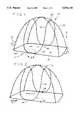
- FIG. 1shows a perspective view of the preferred embodiment of the erected tent frame.
- FIG. 6is an axial cross section of the connector, taken at line 6--6 on FIG. 4.
- FIG. 7is a perspective view of a tent according to this invention in its fully erected position.
- FIG. 8is an enlarged view of the area shown in circle 8 of FIG. 7, illustrating connection of the shock strut to an arcuate section of the upper loop via a twist clip.
- FIG. 9is an enlarged view of the area shown in circle 9 of FIG. 7, illustrating connection of the fabric to the shock strut via a sewn-in C-clip.
- FIG. 10is an enlarged view of the area shown in circle 10 of FIG. 7, illustrating how the shock strut is attached to the base loop with an eye hook and how the base loop runs through pockets sewn into the tent fabric.
- FIG. 1shows the frame 10 of the tent 86 in its fully erected state.
- the frame 10comprises first and second open-ended arcuate sections 13 and 15, respectively to form a base loop 14, first and second open-ended arcuate sections 17 and 19 to form an upper loop 18 and two shock struts 22.
- the base loop 14is semi-elliptical in shape
- the upper loops 18is shape like an upward curving semi-ellipse
- the shock struts 22are shaped like arches.
- the arcuate sections 13 and 15, and 17 and 19, respectively, which form the base loop 14 and the upper loop 18can be made of any resilient filiform material such as spring wire, composite rod or high strength plastic rod.
- the shock strut 22is of conventional design.
- the strut 22is made era series of tubular segments 70 of varying curvature with widened ends 74. In this way the segments 70 can be inserted into one another to form an arch shape.
- a bungee cord(not illustrated) which is retained internally at either end of the strut 22.
- To assemble the strut 22it is only necessary to allow the bungee to pull all the segments 70 into engagement. To disassemble it is only necessary to pull the segments 70 away from one another.
- FIG. 1shows that the opposing, first and second arcuate sections 17 and 19 link to form the base loop 14 which essentially a complete, planar ellipse and the opposing first and second arcuate sections 17 and 19 link to form the upper loop 18 which is a saddle shaped structure.
- the shock struts 22are connected to the first and second arcuate sections 13 and 15 by eye hooks 30 and to the first and second arcuate sections 17 and 19 by twist clips 34. These connections will be described in more detail below.
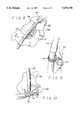
- the preferred embodiment of the connector 26is illustrated in FIGS. 3, 4, 5 and 6.
- the connector 26has an elongated body 42 with a through-bore 54.
- One end of the connector 26is a fixed end 46 and the other is a insertable end 50.
- the through-bore 54goes completely through the body 42 from the fixed end 46 to the insertable end 50.
- the elongated body 42has the shape of multiple, parallel, partial, interconnected, fight circular cylinders. In the preferred embodiment, elongated body 42 has the shape of two interconnected cylinders.
- FIG. 3illustrates the preferred dimensions for the preferred connector 26. Dimension A is about 3/32 in., dimension B is about 3/16 in., dimension C is about 5/8 in., dimension D is about 5/16 in. and dimension E is about 5 in. In alternate embodiments the elongated body 42 can have the shape of three or more interconnected cylinders.
- the connector 26is preferably made as an aluminum extrusion. However, it could be made from other metals, composite
- FIG. 4is a magnified detail of the contents of circle 4 of FIG. 1.
- FIG. 4illustrates the connector 26 assembled into the preferred tent frame 10.
- FIG. 4shows how the terminal ends 58 and, 60 of the first and second arcuate sections 17 and 19, respectively 14 as well as the ends 62, 64 of the upper bops 18 are inserted into the bore 54 at either end 46, 50 of the elongated body 42.
- FIG. 4shows ends terminal ends 58 inserted into the fixed end 46 of the elongated body 42.
- the arcuate sections that from the base loop 14 and the upper loop 18, respectively,are symmetrical, the exact orientation is immaterial.
- the dimension of the bore 54is such that the terminal ends 58, 60, 62, 64 will be retained internally in the preferred embodiment largely by friction between the arcuate sections 13 and 15 of base loop 14 and arcuate sections 17 and 19 of upper loop 18; and the elongated body 42.
- the depth of penetration of the terminal ends 58, 60, 62, 64 into the bore 54can be varied but in the preferred embodiment will extend midway as shown in FIG. 6.
- the terminal ends 58, 62are retained inside the bore 54 of the fixed end 46 by swaging. This results in a swaging depression 66 close to the fixed end 46. While swaging is the preferred method of attachment, other means of attachment, such as welding or adhesive bonding could also be used, especially if the connector 26 is not made out of an aluminum extrusion.
- FIG. 5is a transverse cross section of the assembled connector 26 at the location illustrated in FIG. 4.
- FIG. 5clearly shows swaging depression 66 of the elongated body 42 as a result of the swaging operation, which secures the terminal ends 58,62 inside the bore 54.
- FIG. 6is a axial cross section of the assembled connector 26 at the location illustrated in FIG. 4.
- FIG. 6again shows the swaging depression 66 of the elongated body 42 which traps the terminal 58 inside the bore 54 at the fixed end 46 of the connector 26.
- FIG. 6also shows, schematically, the loose fit of the terminal end 60 inside the bore 54 at the insertable end 50 of the connector 26.
- the terminal end 60can be inserted into and removed from the bore 54, be rotated inside the bore 54, and swiveled from side to side. All these motions are shown by arrows on FIG. 6.
- the terminal ends 60 and 64are retained inside the bore 54 at the insatiable end 50 of the connector 26 mainly by friction.
- the mount of frictional force required to move terminal ends 60 and 64is dictated by the diameter of the terminal ends 60 and 64 of arcuate sections 15 and 19 in relation to dimensions of the bore 54 and the tension in the arcuate sections 15 and 19.
- FIG. 7shows the fully erected tent 86 in accordance with this invention, with the fabric covering 90 draped over and attached to the frame 10.
- attachmentis made by means of sleeves 92, sewn into the fabric 90 and clips attached by sewing to the fabric 90.
- the fabric covering 90is provided with a door 96 and one or more windows 98.
- FIG. 8illustrates connection of the shock strut 22 to the upper loop 18 by means of a conventional twist clip 34, which protrudes through a hole 106 in the fabric 90.
- a conventional twist clip 34which protrudes through a hole 106 in the fabric 90.
- One of the sleeves 92is better illustrated in this Figure. Alternate methods of attachment are commercially available.
- FIG. 9illustrates attachment of the fabric 90 to the shock strut 22 by means of a C-clip 94.
- the clip 94is attached to a tab 110 which is sewn on the fabric 90.
- Other conventional methods to make this attachmentare available on the marketplace.
- FIG. 10illustrates attachment of the shock strut 22 to the base loop 14.
- An eye hook 30is fastened into the end of the shock strut 22.
- This eye hook 30encircles the loop 14 forming a permanent slidable and rotatable attachment. Sliding and rotational motions are shown by arrows on the Figure.
- This Figureagain provides a better illustration of a typical sleeve 92.
- the tent 86is designed so that, by coiling the frame 10, the tent 86 can be quickly and easily made into a disk for convenient transportation and storage. Storing the tent 86 is accomplished by manually pulling apart the segments 70 of the shock struts 22, coiling the frame 10 and securing the tent 86 in this position. When it is desired to use the tent 86, the frame 10 is allowed to assume its unconstrained shape and the segments 70 of the shock struts 22 are manually reassembled. It takes approximately two minutes to erect or flatten the tent 86. While all loops 14, 16, 18, 20 have been described as having particular shapes, other shapes can be used.
- FIG. 2illustrates an alternate embodiment of the frame 10 for use with the fast erecting tent 86.
- This embodimentthere is only one base loop 16, upper loop 20 and connector 26.
- the base loop 16is comprised of a single arcuate section that is approximately a complete planar ellipse.
- the upper loop 20forms an almost complete saddle shape.
- the base loop 16 and upper loop 20 loopsare linked via the signal connector 26 which is located in the front 11 of the frame 10.
- the base loop 16 and upper loop 20are fastened to each other by means of a standard clip 38.
- FIGS. 1 and 2illustrate embodiments of this invention having either first and second open-ended arcuate sections 17 and 19 that form the upper loop 18 or a single arcuate section that forms the single upper loop 20, the present invention could have additional arcuate sections to form additional partial upper loops or that approximate the form of a complete loop.
Landscapes
- Engineering & Computer Science (AREA)
- Architecture (AREA)
- Civil Engineering (AREA)
- Structural Engineering (AREA)
- Tents Or Canopies (AREA)
- Vehicle Body Suspensions (AREA)
- Axle Suspensions And Sidecars For Cycles (AREA)
- Eye Examination Apparatus (AREA)
- Crystals, And After-Treatments Of Crystals (AREA)
- Analysing Materials By The Use Of Radiation (AREA)
- Other Investigation Or Analysis Of Materials By Electrical Means (AREA)
Abstract
Description
Claims (15)
Priority Applications (7)
| Application Number | Priority Date | Filing Date | Title |
|---|---|---|---|
| US08/546,591US5676168A (en) | 1995-10-23 | 1995-10-23 | Fast-erecting tent |
| AT96937737TATE236322T1 (en) | 1995-10-23 | 1996-10-23 | QUICK BUILD TENT |
| AU75207/96AAU703654B2 (en) | 1995-10-23 | 1996-10-23 | Fast-erecting tent |
| DK96937737TDK0857245T3 (en) | 1995-10-23 | 1996-10-23 | Fast travel tent |
| EP96937737AEP0857245B1 (en) | 1995-10-23 | 1996-10-23 | Fast-erecting tent |
| PCT/US1996/017065WO1997015738A1 (en) | 1995-10-23 | 1996-10-23 | Fast-erecting tent |
| DE69627169TDE69627169T2 (en) | 1995-10-23 | 1996-10-23 | SCHNELLBAUZELT |
Applications Claiming Priority (1)
| Application Number | Priority Date | Filing Date | Title |
|---|---|---|---|
| US08/546,591US5676168A (en) | 1995-10-23 | 1995-10-23 | Fast-erecting tent |
Publications (1)
| Publication Number | Publication Date |
|---|---|
| US5676168Atrue US5676168A (en) | 1997-10-14 |
Family
ID=24181109
Family Applications (1)
| Application Number | Title | Priority Date | Filing Date |
|---|---|---|---|
| US08/546,591Expired - LifetimeUS5676168A (en) | 1995-10-23 | 1995-10-23 | Fast-erecting tent |
Country Status (7)
| Country | Link |
|---|---|
| US (1) | US5676168A (en) |
| EP (1) | EP0857245B1 (en) |
| AT (1) | ATE236322T1 (en) |
| AU (1) | AU703654B2 (en) |
| DE (1) | DE69627169T2 (en) |
| DK (1) | DK0857245T3 (en) |
| WO (1) | WO1997015738A1 (en) |
Cited By (76)
| Publication number | Priority date | Publication date | Assignee | Title |
|---|---|---|---|---|
| US5809592A (en)* | 1995-09-18 | 1998-09-22 | Creative Toy Products, Inc. | Self-erecting play yard structure |
| US5941265A (en)* | 1996-09-20 | 1999-08-24 | Patent Category Corp. | Collapsible structures having overlapping support loops |
| US5975101A (en)* | 1996-09-20 | 1999-11-02 | Patent Category Corp. | Collapsible sunshields, partitions and shade structures having overlapping support loops |
| US5979976A (en)* | 1998-04-10 | 1999-11-09 | Ferencik; Mark J. | Foldable support structure |
| US6030300A (en)* | 1997-04-11 | 2000-02-29 | Patent Catergory Corp. | Collapsible structures |
| US6032685A (en)* | 1996-09-20 | 2000-03-07 | Patent Category Corp. | Collapsible structures having overlapping support loops |
| US6092544A (en)* | 1996-09-20 | 2000-07-25 | Patent Category Corp. | Collapsible structures having overlapping support loops |
| US6098349A (en)* | 1998-09-22 | 2000-08-08 | Patent Category Corp. | Collapsible structures |
| US6109282A (en)* | 1998-10-21 | 2000-08-29 | Yoon; Young W. | Self-erecting loop structure |
| US6138701A (en)* | 1996-09-20 | 2000-10-31 | Patent Category Corp. | Collapsible structures having overlapping support loops |
| US6155281A (en)* | 1996-12-26 | 2000-12-05 | Patent Category Corp. | Collapsible structures |
| WO2001007732A1 (en)* | 1999-07-27 | 2001-02-01 | Mountain Safety Research, Inc. | Tent pole clip |
| US6213191B1 (en) | 1999-01-29 | 2001-04-10 | Steelcase Development Inc. | Screen |
| US6289910B1 (en) | 1999-07-08 | 2001-09-18 | Patent Category Corp. | Collapsible structures |
| US6311709B1 (en) | 1999-12-23 | 2001-11-06 | Billwin Auto Accessories, Ltd. | Self-erecting, collapsible and foldable dome structure |
| US6325086B1 (en) | 1999-10-18 | 2001-12-04 | Worlds Apart Limited | Collapsible fabric structures with coilable supports |
| GB2365458A (en)* | 2000-06-17 | 2002-02-20 | Aarn Tate | Dome tent |
| US6360761B1 (en) | 1991-09-24 | 2002-03-26 | Patent Category Corp. | Collapsible play structures |
| US6360760B1 (en)* | 1999-12-03 | 2002-03-26 | Billwin Auto Accessories Limited | Self-erecting and collapsible shelter |
| US6363955B1 (en)* | 2000-01-10 | 2002-04-02 | Billwin Auto Accessories, Ltd. | Self-deploying tubular enclosure |
| US6450187B1 (en) | 1999-02-16 | 2002-09-17 | Yj (Usa) | Reinforced support member and method |
| US6478038B1 (en)* | 2000-08-04 | 2002-11-12 | Gray Matter Holdings, Llc | Collapsible shade for a towel mat |
| US6491052B1 (en) | 2000-05-26 | 2002-12-10 | Patent Category Corp. | Collapsible panels having multiple frame members |
| US6499498B1 (en) | 1996-09-20 | 2002-12-31 | Patent Category Corp. | Collapsible structures having overlapping support loops |
| US6514149B2 (en) | 2000-01-07 | 2003-02-04 | Young W. Yoon | Multiloop golf net assembly |
| US6517444B1 (en) | 2000-08-30 | 2003-02-11 | Young W. Yoon | Upright golf net assembly |
| US6579196B1 (en) | 1999-07-16 | 2003-06-17 | Young W. Yoon | Modular all sports net assembly |
| US6595227B2 (en) | 2001-01-19 | 2003-07-22 | Gray Matter Holdings, Llc | Self-opening shades and methods of using the same |
| US20030181264A1 (en)* | 1999-07-16 | 2003-09-25 | Yoon Young W. | Modular all sports net assembly |
| US20040020311A1 (en)* | 2002-07-30 | 2004-02-05 | Cullion Rebecca Noel | Method and apparatus for differential test probe retention with compliant Z-axis positioning |
| US6702119B2 (en) | 2001-11-27 | 2004-03-09 | Pro-Mart Industries, Inc. | Popup wardrobe |
| US6739095B2 (en) | 2002-01-25 | 2004-05-25 | Peter N. Glynos | Tent with anchors |
| US20040128319A1 (en)* | 2002-08-08 | 2004-07-01 | Versaly Games, Inc. | System and method for automatically finding gaming partners based on pre-established criteria |
| US20040168714A1 (en)* | 1991-09-24 | 2004-09-02 | Patent Category Corporation | Collapsible structures |
| US20040221885A1 (en)* | 1999-04-19 | 2004-11-11 | Yu Zheng | Floating collapsible play structures |
| US20050022852A1 (en)* | 1998-12-09 | 2005-02-03 | Patent Category Corp. | Multipurpose collapsible panels |
| US20050044630A1 (en)* | 2003-08-27 | 2005-03-03 | Danaher Thomas C. | Bed-tent |
| US20050050828A1 (en)* | 2002-02-07 | 2005-03-10 | Vincent Gallix | Flexibly assembled three-dimensional dynamic structure |
| US20050197212A1 (en)* | 2004-03-03 | 2005-09-08 | Turcot Jean-Marc D. | Inflatable sport ball arresting structure |
| US20050236026A1 (en)* | 2004-04-22 | 2005-10-27 | Anticoli Jennifer C | Portable baby tent |
| US20060037553A1 (en)* | 2004-08-16 | 2006-02-23 | Miller Catherine L | Pet safety enclosure method and apparatus |
| US20060249191A1 (en)* | 2004-05-14 | 2006-11-09 | Patent Category Corp. | Collapsible panels having multiple frame members |
| US7137399B1 (en)* | 2003-05-13 | 2006-11-21 | Ransom Robert M | Collapsible structure with top supporting elements |
| US20060272695A1 (en)* | 2004-11-17 | 2006-12-07 | Benjamin Mettavant | Self-deployable tent including an inside chamber |
| US20060289047A1 (en)* | 1996-12-26 | 2006-12-28 | Yu Zheng | Collapsible structures |
| USD534615S1 (en)* | 2005-12-29 | 2007-01-02 | Van Aalst Roy | Tent |
| US20070066162A1 (en)* | 2005-09-20 | 2007-03-22 | Yu Zheng | Floating assemblies |
| US20070095377A1 (en)* | 2005-11-03 | 2007-05-03 | American Recreation Products, Inc. | Curved base tent |
| US20070137683A1 (en)* | 2004-01-05 | 2007-06-21 | Price R J | Fast-erecting portable structure |
| US20080169015A1 (en)* | 2007-01-12 | 2008-07-17 | Wei Hen Yang | Foldable frame structure |
| US20090021902A1 (en)* | 2000-05-01 | 2009-01-22 | Yu Zheng | Collapsible structures having enhancements |
| US20090084798A1 (en)* | 2007-08-31 | 2009-04-02 | Rothweil Daniel A | Collapsible food protective enclosure |
| US20090183758A1 (en)* | 2005-12-22 | 2009-07-23 | Vasko Mitkov Gospodinov | Selferecting Structure |
| US20090212050A1 (en)* | 2005-02-23 | 2009-08-27 | Patent Category Corp. | Collapsible structures with liners |
| US20090276937A1 (en)* | 2008-05-06 | 2009-11-12 | Yu Zheng | Collapsible costumes |
| USD625053S1 (en)* | 2010-04-05 | 2010-10-05 | Denis John Thornton | Hay feeder |
| US20110085750A1 (en)* | 2009-10-14 | 2011-04-14 | Wen-Tsan Wang | Folding collapsible bag |
| US20120062000A1 (en)* | 2010-09-15 | 2012-03-15 | Monahan Products, Inc. | Infant seat cover |
| US8186369B2 (en) | 2008-05-14 | 2012-05-29 | Swimways Corporation | Collapsible shelter |
| US20120317716A1 (en)* | 2011-06-14 | 2012-12-20 | Serpolet | Self-deployable cot |
| US8342226B2 (en) | 2010-09-23 | 2013-01-01 | Patent Category Corp. | Collapsible sunshade |
| US8567424B2 (en) | 2010-07-23 | 2013-10-29 | Gregory P. Hill, Sr. | Tent and tent frame |
| US20130291918A1 (en)* | 2012-05-04 | 2013-11-07 | Emma Lovell | Cover assembly for an infant bed |
| US8667626B2 (en) | 2010-10-05 | 2014-03-11 | Patent Category Corp | Collapsible baby play station |
| USD705998S1 (en)* | 2013-06-01 | 2014-05-27 | Denis John Thornton | Hay feeder |
| US20160053508A1 (en)* | 2012-07-17 | 2016-02-25 | Thomas GUTWENGER | Tent structure or sun protection structure |
| USD858675S1 (en)* | 2018-06-26 | 2019-09-03 | Huangshan City Huilingyang Outdoor Products Co. | Tent |
| USD872209S1 (en)* | 2018-12-14 | 2020-01-07 | Wenjie Zhu | Tent |
| USD872210S1 (en)* | 2018-12-17 | 2020-01-07 | Wenjie Zhu | Tent |
| USD872818S1 (en)* | 2018-12-13 | 2020-01-14 | Wenjie Zhu | Tent |
| US11140997B2 (en)* | 2016-08-31 | 2021-10-12 | Dovetail Essentials, LLC | Crib accessory |
| US11457705B2 (en)* | 2017-10-09 | 2022-10-04 | Aviad Berger | Folding table |
| US20230183998A1 (en)* | 2021-12-10 | 2023-06-15 | Danielle Fujii | Portable light blocking den |
| US20230304317A1 (en)* | 2022-03-23 | 2023-09-28 | Lun Xu | Collapsible Tent Structures |
| USD1090753S1 (en)* | 2024-01-18 | 2025-08-26 | Nanjing Yixiu Sports Technology Co., Ltd. | Golf training strike net |
| USD1091738S1 (en)* | 2024-01-18 | 2025-09-02 | Nanjing Yixiu Sports Technology Co., Ltd. | Golf training strike net |
Families Citing this family (2)
| Publication number | Priority date | Publication date | Assignee | Title |
|---|---|---|---|---|
| US6850849B1 (en) | 2001-06-20 | 2005-02-01 | Curtis Roys | Fluid flow monitor and control system |
| WO2012139161A1 (en)* | 2011-04-11 | 2012-10-18 | Bob And Ahmed Enterprises Pty Ltd. | An adjustable food covering support device |
Citations (11)
| Publication number | Priority date | Publication date | Assignee | Title |
|---|---|---|---|---|
| DE702098C (en)* | 1936-12-10 | 1941-01-30 | Auergesellschaft Akt Ges | air hoses, especially for breathing apparatus |
| US2884478A (en)* | 1955-04-20 | 1959-04-28 | Fargo Mfg Co Inc | Strand connector |
| US3387080A (en)* | 1966-07-25 | 1968-06-04 | Burndy Corp | Splice connector with locking insert |
| DE1928653A1 (en)* | 1969-06-06 | 1970-12-10 | Salewa Lederwarenfabrik Gmbh | Tent with tent poles |
| US4858634A (en)* | 1988-07-18 | 1989-08-22 | Mcleese Eddie S | Self erecting structure |
| US4899965A (en)* | 1988-02-16 | 1990-02-13 | Usui Kokusai Sangyo Kaisha Ltd. | Apparatus for collectively fixing pipes |
| US4926892A (en)* | 1989-11-15 | 1990-05-22 | Krohm, Inc. | Temporary enclosure structure |
| EP0401398A1 (en)* | 1988-06-06 | 1990-12-12 | Helmut Dröschel | Igloo tent |
| US5163461A (en)* | 1991-10-17 | 1992-11-17 | Ivanovich Michael K | Self-erecting shelter |
| US5385165A (en)* | 1994-02-03 | 1995-01-31 | Hazinski; Daniel P. | Hunting blind |
| US5396917A (en)* | 1994-02-03 | 1995-03-14 | Hazinski; Daniel P. | Self erecting high top tent |
Family Cites Families (4)
| Publication number | Priority date | Publication date | Assignee | Title |
|---|---|---|---|---|
| US3960161A (en) | 1974-11-05 | 1976-06-01 | Norman Lowell R | Portable structure |
| US3990463A (en) | 1975-10-17 | 1976-11-09 | Lowell Robert Norman | Portable structure |
| US5370145A (en)* | 1992-10-26 | 1994-12-06 | Wu; Wen-Yu | Easy shield |
| US5407291A (en) | 1994-02-03 | 1995-04-18 | Pop-Tent, Inc. | Wire connector and method |
- 1995
- 1995-10-23USUS08/546,591patent/US5676168A/ennot_activeExpired - Lifetime
- 1996
- 1996-10-23WOPCT/US1996/017065patent/WO1997015738A1/enactiveIP Right Grant
- 1996-10-23DKDK96937737Tpatent/DK0857245T3/enactive
- 1996-10-23ATAT96937737Tpatent/ATE236322T1/ennot_activeIP Right Cessation
- 1996-10-23AUAU75207/96Apatent/AU703654B2/ennot_activeCeased
- 1996-10-23EPEP96937737Apatent/EP0857245B1/ennot_activeExpired - Lifetime
- 1996-10-23DEDE69627169Tpatent/DE69627169T2/ennot_activeExpired - Lifetime
Patent Citations (11)
| Publication number | Priority date | Publication date | Assignee | Title |
|---|---|---|---|---|
| DE702098C (en)* | 1936-12-10 | 1941-01-30 | Auergesellschaft Akt Ges | air hoses, especially for breathing apparatus |
| US2884478A (en)* | 1955-04-20 | 1959-04-28 | Fargo Mfg Co Inc | Strand connector |
| US3387080A (en)* | 1966-07-25 | 1968-06-04 | Burndy Corp | Splice connector with locking insert |
| DE1928653A1 (en)* | 1969-06-06 | 1970-12-10 | Salewa Lederwarenfabrik Gmbh | Tent with tent poles |
| US4899965A (en)* | 1988-02-16 | 1990-02-13 | Usui Kokusai Sangyo Kaisha Ltd. | Apparatus for collectively fixing pipes |
| EP0401398A1 (en)* | 1988-06-06 | 1990-12-12 | Helmut Dröschel | Igloo tent |
| US4858634A (en)* | 1988-07-18 | 1989-08-22 | Mcleese Eddie S | Self erecting structure |
| US4926892A (en)* | 1989-11-15 | 1990-05-22 | Krohm, Inc. | Temporary enclosure structure |
| US5163461A (en)* | 1991-10-17 | 1992-11-17 | Ivanovich Michael K | Self-erecting shelter |
| US5385165A (en)* | 1994-02-03 | 1995-01-31 | Hazinski; Daniel P. | Hunting blind |
| US5396917A (en)* | 1994-02-03 | 1995-03-14 | Hazinski; Daniel P. | Self erecting high top tent |
Cited By (133)
| Publication number | Priority date | Publication date | Assignee | Title |
|---|---|---|---|---|
| US20040168714A1 (en)* | 1991-09-24 | 2004-09-02 | Patent Category Corporation | Collapsible structures |
| US6360761B1 (en) | 1991-09-24 | 2002-03-26 | Patent Category Corp. | Collapsible play structures |
| US7472715B2 (en) | 1991-09-24 | 2009-01-06 | Patent Category Corp. | Collapsible structures |
| US6705338B2 (en) | 1991-09-24 | 2004-03-16 | Patent Category Corp. | Collapsible structures |
| US5809592A (en)* | 1995-09-18 | 1998-09-22 | Creative Toy Products, Inc. | Self-erecting play yard structure |
| US6032685A (en)* | 1996-09-20 | 2000-03-07 | Patent Category Corp. | Collapsible structures having overlapping support loops |
| US5975101A (en)* | 1996-09-20 | 1999-11-02 | Patent Category Corp. | Collapsible sunshields, partitions and shade structures having overlapping support loops |
| US7516750B2 (en) | 1996-09-20 | 2009-04-14 | Patent Category Corp. | Collapsible structures having overlapping support loops |
| US7159601B2 (en) | 1996-09-20 | 2007-01-09 | Patent Category Corp. | Collapsible structures having overlapping support loops |
| US6138701A (en)* | 1996-09-20 | 2000-10-31 | Patent Category Corp. | Collapsible structures having overlapping support loops |
| US5941265A (en)* | 1996-09-20 | 1999-08-24 | Patent Category Corp. | Collapsible structures having overlapping support loops |
| US20040250483A1 (en)* | 1996-09-20 | 2004-12-16 | Patent Category Corp. | Collapsible structures having overlapping support loops |
| US6092544A (en)* | 1996-09-20 | 2000-07-25 | Patent Category Corp. | Collapsible structures having overlapping support loops |
| US6684894B2 (en) | 1996-09-20 | 2004-02-03 | Patent Category Corp. | Collapsible structures having overlapping support loops |
| US6499498B1 (en) | 1996-09-20 | 2002-12-31 | Patent Category Corp. | Collapsible structures having overlapping support loops |
| US6209557B1 (en) | 1996-12-26 | 2001-04-03 | Patent Category Corp. | Collapsible structures |
| US7703228B2 (en) | 1996-12-26 | 2010-04-27 | Patent Category Corp. | Collapsible structures |
| US6604537B2 (en) | 1996-12-26 | 2003-08-12 | Patent Category Corp. | Collapsible structures |
| US20060289047A1 (en)* | 1996-12-26 | 2006-12-28 | Yu Zheng | Collapsible structures |
| US6155281A (en)* | 1996-12-26 | 2000-12-05 | Patent Category Corp. | Collapsible structures |
| US6264573B1 (en) | 1997-04-11 | 2001-07-24 | Patent Category Corp. | Collapsible structures basketball goal |
| US20060183573A1 (en)* | 1997-04-11 | 2006-08-17 | Patent Category Corp. | Collapsible structures |
| US6030300A (en)* | 1997-04-11 | 2000-02-29 | Patent Catergory Corp. | Collapsible structures |
| US6461257B2 (en) | 1997-04-11 | 2002-10-08 | Patent Category Corp. | Collapsible structures |
| US20040209713A1 (en)* | 1997-04-11 | 2004-10-21 | Yu Zheng | Collapsible structures |
| US7267625B2 (en) | 1997-04-11 | 2007-09-11 | Patent Category Corp. | Collapsible structures |
| US6736740B2 (en) | 1997-04-11 | 2004-05-18 | Patent Category Corp. | Collapsible structures |
| US7048654B2 (en) | 1997-04-11 | 2006-05-23 | Patent Category Corp. | Collapsible structures |
| US20080026880A1 (en)* | 1997-04-11 | 2008-01-31 | Patent Category Corp. | Collapsible structures |
| US7682268B2 (en) | 1997-04-11 | 2010-03-23 | Patent Category Corp. | Collapsible structures |
| US5979976A (en)* | 1998-04-10 | 1999-11-09 | Ferencik; Mark J. | Foldable support structure |
| US7225822B1 (en)* | 1998-09-22 | 2007-06-05 | Patent Category Corp. | Collapsible structures |
| US7575011B2 (en) | 1998-09-22 | 2009-08-18 | Patent Category Corp. | Collapsible structures |
| US6098349A (en)* | 1998-09-22 | 2000-08-08 | Patent Category Corp. | Collapsible structures |
| US20070246093A1 (en)* | 1998-09-22 | 2007-10-25 | Yu Zheng | Collapsible structures |
| US6109282A (en)* | 1998-10-21 | 2000-08-29 | Yoon; Young W. | Self-erecting loop structure |
| US20060016468A1 (en)* | 1998-12-09 | 2006-01-26 | Patent Category Corp. | Multipurpose collapsible panels |
| US20050022852A1 (en)* | 1998-12-09 | 2005-02-03 | Patent Category Corp. | Multipurpose collapsible panels |
| US6213191B1 (en) | 1999-01-29 | 2001-04-10 | Steelcase Development Inc. | Screen |
| US6450187B1 (en) | 1999-02-16 | 2002-09-17 | Yj (Usa) | Reinforced support member and method |
| US20040221885A1 (en)* | 1999-04-19 | 2004-11-11 | Yu Zheng | Floating collapsible play structures |
| US20090050188A1 (en)* | 1999-07-08 | 2009-02-26 | Patent Category Corp. | Collapsible structures |
| US20040149328A1 (en)* | 1999-07-08 | 2004-08-05 | Patent Category Corp. | Collapsible structures |
| US6494224B2 (en) | 1999-07-08 | 2002-12-17 | Patent Category Corp. | Collapsible structures |
| US20060076044A1 (en)* | 1999-07-08 | 2006-04-13 | Patent Category Corp. | Collapsible structures |
| US6289910B1 (en) | 1999-07-08 | 2001-09-18 | Patent Category Corp. | Collapsible structures |
| US6579196B1 (en) | 1999-07-16 | 2003-06-17 | Young W. Yoon | Modular all sports net assembly |
| US6966852B2 (en) | 1999-07-16 | 2005-11-22 | Yoon Young W | Modular all sports net assembly |
| US20030181264A1 (en)* | 1999-07-16 | 2003-09-25 | Yoon Young W. | Modular all sports net assembly |
| WO2001007732A1 (en)* | 1999-07-27 | 2001-02-01 | Mountain Safety Research, Inc. | Tent pole clip |
| US6325086B1 (en) | 1999-10-18 | 2001-12-04 | Worlds Apart Limited | Collapsible fabric structures with coilable supports |
| US6360760B1 (en)* | 1999-12-03 | 2002-03-26 | Billwin Auto Accessories Limited | Self-erecting and collapsible shelter |
| US6311709B1 (en) | 1999-12-23 | 2001-11-06 | Billwin Auto Accessories, Ltd. | Self-erecting, collapsible and foldable dome structure |
| US6514149B2 (en) | 2000-01-07 | 2003-02-04 | Young W. Yoon | Multiloop golf net assembly |
| US6363955B1 (en)* | 2000-01-10 | 2002-04-02 | Billwin Auto Accessories, Ltd. | Self-deploying tubular enclosure |
| US20090021902A1 (en)* | 2000-05-01 | 2009-01-22 | Yu Zheng | Collapsible structures having enhancements |
| US7836906B2 (en) | 2000-05-01 | 2010-11-23 | Patent Category Corp. | Collapsible structures having enhancements |
| US20040211454A1 (en)* | 2000-05-26 | 2004-10-28 | Patent Category Corp. | Collapsible panels having multiple frame members |
| US6736152B2 (en) | 2000-05-26 | 2004-05-18 | Patent Category Corp. | Collapsible panels having multiple frame members |
| US7073523B2 (en) | 2000-05-26 | 2006-07-11 | Patent Category Corp. | Collapsible panels having multiple frame members |
| US6491052B1 (en) | 2000-05-26 | 2002-12-10 | Patent Category Corp. | Collapsible panels having multiple frame members |
| GB2365458A (en)* | 2000-06-17 | 2002-02-20 | Aarn Tate | Dome tent |
| US6478038B1 (en)* | 2000-08-04 | 2002-11-12 | Gray Matter Holdings, Llc | Collapsible shade for a towel mat |
| US6517444B1 (en) | 2000-08-30 | 2003-02-11 | Young W. Yoon | Upright golf net assembly |
| US6942005B2 (en) | 2001-01-19 | 2005-09-13 | Kelsyus, Llc | Self-opening enclosure |
| US6595227B2 (en) | 2001-01-19 | 2003-07-22 | Gray Matter Holdings, Llc | Self-opening shades and methods of using the same |
| US6702119B2 (en) | 2001-11-27 | 2004-03-09 | Pro-Mart Industries, Inc. | Popup wardrobe |
| US6739095B2 (en) | 2002-01-25 | 2004-05-25 | Peter N. Glynos | Tent with anchors |
| US20050050828A1 (en)* | 2002-02-07 | 2005-03-10 | Vincent Gallix | Flexibly assembled three-dimensional dynamic structure |
| US20040020311A1 (en)* | 2002-07-30 | 2004-02-05 | Cullion Rebecca Noel | Method and apparatus for differential test probe retention with compliant Z-axis positioning |
| US20040128319A1 (en)* | 2002-08-08 | 2004-07-01 | Versaly Games, Inc. | System and method for automatically finding gaming partners based on pre-established criteria |
| US7137399B1 (en)* | 2003-05-13 | 2006-11-21 | Ransom Robert M | Collapsible structure with top supporting elements |
| US7392555B2 (en) | 2003-08-27 | 2008-07-01 | Happy Camper, Inc. | Bed-tent |
| US20050274406A1 (en)* | 2003-08-27 | 2005-12-15 | Danaher Thomas C | Bed-tent |
| US20060064818A1 (en)* | 2003-08-27 | 2006-03-30 | Danaher Thomas C | Bed-tent |
| US20050044630A1 (en)* | 2003-08-27 | 2005-03-03 | Danaher Thomas C. | Bed-tent |
| US6952844B2 (en) | 2003-08-27 | 2005-10-11 | Danaher Thomas C | Bed-tent |
| US7174584B2 (en) | 2003-08-27 | 2007-02-13 | Danaher Thomas C | Bed-tent |
| US20070137683A1 (en)* | 2004-01-05 | 2007-06-21 | Price R J | Fast-erecting portable structure |
| US7954504B2 (en) | 2004-01-05 | 2011-06-07 | Price R Justin | Fast-erecting portable structure |
| US20050197212A1 (en)* | 2004-03-03 | 2005-09-08 | Turcot Jean-Marc D. | Inflatable sport ball arresting structure |
| US7201177B2 (en) | 2004-04-22 | 2007-04-10 | Jennifer Cobb Anticoli | Portable baby tent |
| US20050236026A1 (en)* | 2004-04-22 | 2005-10-27 | Anticoli Jennifer C | Portable baby tent |
| US20060249191A1 (en)* | 2004-05-14 | 2006-11-09 | Patent Category Corp. | Collapsible panels having multiple frame members |
| WO2006023727A3 (en)* | 2004-08-16 | 2009-07-16 | Wild Whiskers | Pet safety enclosure method and apparatus |
| US7523719B2 (en)* | 2004-08-16 | 2009-04-28 | Wild Whiskers Llc | Pet safety enclosure method and apparatus |
| US20060037553A1 (en)* | 2004-08-16 | 2006-02-23 | Miller Catherine L | Pet safety enclosure method and apparatus |
| AU2004324394B2 (en)* | 2004-11-17 | 2011-07-14 | Decathlon | Self-deployable tent comprising an internal chamber |
| US20060272695A1 (en)* | 2004-11-17 | 2006-12-07 | Benjamin Mettavant | Self-deployable tent including an inside chamber |
| US20080190473A1 (en)* | 2004-11-17 | 2008-08-14 | Benjamin Mettavant | Self-deployable tent including an inside chamber |
| AU2004324394C1 (en)* | 2004-11-17 | 2012-11-29 | Decathlon | Self-deployable tent comprising an internal chamber |
| US7578306B2 (en)* | 2004-11-17 | 2009-08-25 | Decathlon | Self-deployable tent including an inside chamber |
| US20090212050A1 (en)* | 2005-02-23 | 2009-08-27 | Patent Category Corp. | Collapsible structures with liners |
| US20070212958A1 (en)* | 2005-09-20 | 2007-09-13 | Patent Category Corp. | Floating assemblies |
| US20070066162A1 (en)* | 2005-09-20 | 2007-03-22 | Yu Zheng | Floating assemblies |
| US7207857B2 (en) | 2005-09-20 | 2007-04-24 | Patent Category Corp. | Floating assemblies |
| US20070095377A1 (en)* | 2005-11-03 | 2007-05-03 | American Recreation Products, Inc. | Curved base tent |
| US20090183758A1 (en)* | 2005-12-22 | 2009-07-23 | Vasko Mitkov Gospodinov | Selferecting Structure |
| USD534615S1 (en)* | 2005-12-29 | 2007-01-02 | Van Aalst Roy | Tent |
| US20080169015A1 (en)* | 2007-01-12 | 2008-07-17 | Wei Hen Yang | Foldable frame structure |
| US20090084798A1 (en)* | 2007-08-31 | 2009-04-02 | Rothweil Daniel A | Collapsible food protective enclosure |
| US8132585B2 (en)* | 2007-08-31 | 2012-03-13 | D-Squared Product Development | Collapsible food protective enclosure |
| US20090276937A1 (en)* | 2008-05-06 | 2009-11-12 | Yu Zheng | Collapsible costumes |
| US8186369B2 (en) | 2008-05-14 | 2012-05-29 | Swimways Corporation | Collapsible shelter |
| US20110085750A1 (en)* | 2009-10-14 | 2011-04-14 | Wen-Tsan Wang | Folding collapsible bag |
| USD625053S1 (en)* | 2010-04-05 | 2010-10-05 | Denis John Thornton | Hay feeder |
| US8567424B2 (en) | 2010-07-23 | 2013-10-29 | Gregory P. Hill, Sr. | Tent and tent frame |
| US20120062000A1 (en)* | 2010-09-15 | 2012-03-15 | Monahan Products, Inc. | Infant seat cover |
| US8851097B2 (en)* | 2010-09-15 | 2014-10-07 | Monahan Products, LLC | Infant seat cover |
| US8342226B2 (en) | 2010-09-23 | 2013-01-01 | Patent Category Corp. | Collapsible sunshade |
| US8667626B2 (en) | 2010-10-05 | 2014-03-11 | Patent Category Corp | Collapsible baby play station |
| US20120317716A1 (en)* | 2011-06-14 | 2012-12-20 | Serpolet | Self-deployable cot |
| US9179785B2 (en)* | 2011-06-14 | 2015-11-10 | Serpolet | Self-deployable cot |
| US20130291918A1 (en)* | 2012-05-04 | 2013-11-07 | Emma Lovell | Cover assembly for an infant bed |
| US10208499B2 (en)* | 2012-05-04 | 2019-02-19 | Emma Lovell | Cover assembly for an infant bed |
| US20160053508A1 (en)* | 2012-07-17 | 2016-02-25 | Thomas GUTWENGER | Tent structure or sun protection structure |
| USD705998S1 (en)* | 2013-06-01 | 2014-05-27 | Denis John Thornton | Hay feeder |
| US12048381B2 (en) | 2016-08-31 | 2024-07-30 | Slumberpod Llc | Crib accessory |
| US12226022B2 (en) | 2016-08-31 | 2025-02-18 | Slumberpod Llc | Crib accessory |
| US11140997B2 (en)* | 2016-08-31 | 2021-10-12 | Dovetail Essentials, LLC | Crib accessory |
| US20220202200A1 (en)* | 2016-08-31 | 2022-06-30 | Dovetail Essentials, LLC | Crib accessory |
| US11406198B2 (en)* | 2016-08-31 | 2022-08-09 | Slumberpod Llc | Crib accessory |
| US11617450B2 (en)* | 2016-08-31 | 2023-04-04 | Slumberpod Llc | Crib accessory |
| US11457705B2 (en)* | 2017-10-09 | 2022-10-04 | Aviad Berger | Folding table |
| USD858675S1 (en)* | 2018-06-26 | 2019-09-03 | Huangshan City Huilingyang Outdoor Products Co. | Tent |
| USD872818S1 (en)* | 2018-12-13 | 2020-01-14 | Wenjie Zhu | Tent |
| USD872209S1 (en)* | 2018-12-14 | 2020-01-07 | Wenjie Zhu | Tent |
| USD872210S1 (en)* | 2018-12-17 | 2020-01-07 | Wenjie Zhu | Tent |
| US20230183998A1 (en)* | 2021-12-10 | 2023-06-15 | Danielle Fujii | Portable light blocking den |
| US12305414B2 (en)* | 2021-12-10 | 2025-05-20 | Danielle Fujii | Portable light blocking den |
| US20230304317A1 (en)* | 2022-03-23 | 2023-09-28 | Lun Xu | Collapsible Tent Structures |
| USD1090753S1 (en)* | 2024-01-18 | 2025-08-26 | Nanjing Yixiu Sports Technology Co., Ltd. | Golf training strike net |
| USD1091738S1 (en)* | 2024-01-18 | 2025-09-02 | Nanjing Yixiu Sports Technology Co., Ltd. | Golf training strike net |
Also Published As
| Publication number | Publication date |
|---|---|
| ATE236322T1 (en) | 2003-04-15 |
| AU703654B2 (en) | 1999-04-01 |
| DE69627169T2 (en) | 2004-03-04 |
| EP0857245B1 (en) | 2003-04-02 |
| AU7520796A (en) | 1997-05-15 |
| EP0857245A1 (en) | 1998-08-12 |
| DK0857245T3 (en) | 2003-07-21 |
| EP0857245A4 (en) | 1999-01-07 |
| DE69627169D1 (en) | 2003-05-08 |
| WO1997015738A1 (en) | 1997-05-01 |
Similar Documents
| Publication | Publication Date | Title |
|---|---|---|
| US5676168A (en) | Fast-erecting tent | |
| WO1997015738A9 (en) | Fast-erecting tent | |
| US7794374B1 (en) | Elastic device | |
| DE19805183B4 (en) | Foldable tent frame with integrated tent cloth | |
| AU602627B2 (en) | Instantly stable, quickly erectable and quickly collapsible portable structure | |
| US4745936A (en) | Tent | |
| US5546971A (en) | Foldable shelter | |
| US5771912A (en) | Attachment device for erecting a tent | |
| US20020183128A1 (en) | Collapsible net device | |
| US9260881B2 (en) | Quick camp frame system | |
| JPS5885773A (en) | Folding bicycle frame | |
| US6530844B2 (en) | Ball barrier assembly | |
| US6615552B2 (en) | Segmented articulated pole structure | |
| WO1998051890A1 (en) | Pyramidal tent-like structure | |
| US5492288A (en) | Kite framing-member connector | |
| CA1166926A (en) | Tent | |
| US6227218B1 (en) | Tent pole clip | |
| US6722613B1 (en) | Kite having flapping wings | |
| EP0409639A2 (en) | A canopy | |
| US6354317B1 (en) | Tent stabilizer | |
| JP3565819B2 (en) | tent | |
| JP6773407B2 (en) | Flagpole for Nobori flag and Nobori flag using this | |
| KR200495709Y1 (en) | Foldable Mosquito Net | |
| JPS581227Y2 (en) | Tent combination 1 pole | |
| JPH0325655Y2 (en) |
Legal Events
| Date | Code | Title | Description |
|---|---|---|---|
| AS | Assignment | Owner name:TUNED IN SPORTS, MASSACHUSETTS Free format text:ASSIGNMENT OF ASSIGNORS INTEREST;ASSIGNOR:PRICE, WALTER A/K/A/ WALTER L. PRICE AND OUTDOOR INNOVATIONS, LTD ARIZONA, USA;REEL/FRAME:011231/0854 Effective date:20000828 | |
| FPAY | Fee payment | Year of fee payment:4 | |
| AS | Assignment | Owner name:INTER BANK FUNDING CORPORATION, DISTRICT OF COLUMB Free format text:PATENT ASSIGNMENT OF SECURITY;ASSIGNOR:TUNED IN SPORTS, INC.;REEL/FRAME:012199/0065 Effective date:20010614 | |
| FPAY | Fee payment | Year of fee payment:8 | |
| REMI | Maintenance fee reminder mailed | ||
| REIN | Reinstatement after maintenance fee payment confirmed | ||
| FP | Lapsed due to failure to pay maintenance fee | Effective date:20091014 | |
| FEPP | Fee payment procedure | Free format text:PETITION RELATED TO MAINTENANCE FEES FILED (ORIGINAL EVENT CODE: PMFP); ENTITY STATUS OF PATENT OWNER: LARGE ENTITY Free format text:PETITION RELATED TO MAINTENANCE FEES GRANTED (ORIGINAL EVENT CODE: PMFG); ENTITY STATUS OF PATENT OWNER: LARGE ENTITY Free format text:PAT HOLDER NO LONGER CLAIMS SMALL ENTITY STATUS, ENTITY STATUS SET TO UNDISCOUNTED (ORIGINAL EVENT CODE: STOL); ENTITY STATUS OF PATENT OWNER: LARGE ENTITY | |
| PRDP | Patent reinstated due to the acceptance of a late maintenance fee | Effective date:20100319 | |
| FPAY | Fee payment | Year of fee payment:12 | |
| STCF | Information on status: patent grant | Free format text:PATENTED CASE | |
| SULP | Surcharge for late payment |