US5675503A - Adaptive load cycler for controlled reduction of energy use - Google Patents
Adaptive load cycler for controlled reduction of energy useDownload PDFInfo
- Publication number
- US5675503A US5675503AUS08/229,622US22962294AUS5675503AUS 5675503 AUS5675503 AUS 5675503AUS 22962294 AUS22962294 AUS 22962294AUS 5675503 AUS5675503 AUS 5675503A
- Authority
- US
- United States
- Prior art keywords
- energy use
- load
- run time
- time
- average
- Prior art date
- Legal status (The legal status is an assumption and is not a legal conclusion. Google has not performed a legal analysis and makes no representation as to the accuracy of the status listed.)
- Expired - Fee Related
Links
- 230000009467reductionEffects0.000titleclaimsdescription29
- 230000003044adaptive effectEffects0.000titleclaimsdescription21
- 238000000034methodMethods0.000claimsabstractdescription45
- 238000005259measurementMethods0.000claimsabstractdescription14
- 238000012544monitoring processMethods0.000claimsdescription10
- 230000004044responseEffects0.000claimsdescription7
- 230000002596correlated effectEffects0.000claimsdescription5
- 230000001105regulatory effectEffects0.000abstractdescription3
- 230000008901benefitEffects0.000description14
- 238000007726management methodMethods0.000description7
- 230000001351cycling effectEffects0.000description6
- 238000004364calculation methodMethods0.000description5
- 230000001276controlling effectEffects0.000description5
- 230000000694effectsEffects0.000description4
- 230000006870functionEffects0.000description4
- 238000003780insertionMethods0.000description4
- 230000037431insertionEffects0.000description4
- 238000004378air conditioningMethods0.000description3
- 238000001816coolingMethods0.000description3
- 238000013500data storageMethods0.000description3
- 238000010586diagramMethods0.000description3
- 238000010248power generationMethods0.000description3
- 238000011217control strategyMethods0.000description2
- 238000005265energy consumptionMethods0.000description2
- 238000012986modificationMethods0.000description2
- 230000004048modificationEffects0.000description2
- 238000012545processingMethods0.000description2
- 238000005549size reductionMethods0.000description2
- 238000012360testing methodMethods0.000description2
- XLYOFNOQVPJJNP-UHFFFAOYSA-NwaterSubstancesOXLYOFNOQVPJJNP-UHFFFAOYSA-N0.000description2
- 230000003466anti-cipated effectEffects0.000description1
- 238000013459approachMethods0.000description1
- 230000008859changeEffects0.000description1
- 238000004590computer programMethods0.000description1
- 230000000875corresponding effectEffects0.000description1
- 230000003247decreasing effectEffects0.000description1
- 238000013461designMethods0.000description1
- 238000010438heat treatmentMethods0.000description1
- 230000000977initiatory effectEffects0.000description1
- 238000012417linear regressionMethods0.000description1
- 230000014759maintenance of locationEffects0.000description1
- 230000007935neutral effectEffects0.000description1
- 230000011664signalingEffects0.000description1
Images


Classifications
- H—ELECTRICITY
- H02—GENERATION; CONVERSION OR DISTRIBUTION OF ELECTRIC POWER
- H02J—CIRCUIT ARRANGEMENTS OR SYSTEMS FOR SUPPLYING OR DISTRIBUTING ELECTRIC POWER; SYSTEMS FOR STORING ELECTRIC ENERGY
- H02J3/00—Circuit arrangements for AC mains or AC distribution networks
- H02J3/12—Circuit arrangements for AC mains or AC distribution networks for adjusting voltage in AC networks by changing a characteristic of the network load
- H02J3/14—Circuit arrangements for AC mains or AC distribution networks for adjusting voltage in AC networks by changing a characteristic of the network load by switching loads on to, or off from, network, e.g. progressively balanced loading
- H—ELECTRICITY
- H02—GENERATION; CONVERSION OR DISTRIBUTION OF ELECTRIC POWER
- H02J—CIRCUIT ARRANGEMENTS OR SYSTEMS FOR SUPPLYING OR DISTRIBUTING ELECTRIC POWER; SYSTEMS FOR STORING ELECTRIC ENERGY
- H02J2310/00—The network for supplying or distributing electric power characterised by its spatial reach or by the load
- H02J2310/10—The network having a local or delimited stationary reach
- H02J2310/12—The local stationary network supplying a household or a building
- H02J2310/14—The load or loads being home appliances
- Y—GENERAL TAGGING OF NEW TECHNOLOGICAL DEVELOPMENTS; GENERAL TAGGING OF CROSS-SECTIONAL TECHNOLOGIES SPANNING OVER SEVERAL SECTIONS OF THE IPC; TECHNICAL SUBJECTS COVERED BY FORMER USPC CROSS-REFERENCE ART COLLECTIONS [XRACs] AND DIGESTS
- Y02—TECHNOLOGIES OR APPLICATIONS FOR MITIGATION OR ADAPTATION AGAINST CLIMATE CHANGE
- Y02B—CLIMATE CHANGE MITIGATION TECHNOLOGIES RELATED TO BUILDINGS, e.g. HOUSING, HOUSE APPLIANCES OR RELATED END-USER APPLICATIONS
- Y02B70/00—Technologies for an efficient end-user side electric power management and consumption
- Y02B70/30—Systems integrating technologies related to power network operation and communication or information technologies for improving the carbon footprint of the management of residential or tertiary loads, i.e. smart grids as climate change mitigation technology in the buildings sector, including also the last stages of power distribution and the control, monitoring or operating management systems at local level
- Y02B70/3225—Demand response systems, e.g. load shedding, peak shaving
- Y—GENERAL TAGGING OF NEW TECHNOLOGICAL DEVELOPMENTS; GENERAL TAGGING OF CROSS-SECTIONAL TECHNOLOGIES SPANNING OVER SEVERAL SECTIONS OF THE IPC; TECHNICAL SUBJECTS COVERED BY FORMER USPC CROSS-REFERENCE ART COLLECTIONS [XRACs] AND DIGESTS
- Y04—INFORMATION OR COMMUNICATION TECHNOLOGIES HAVING AN IMPACT ON OTHER TECHNOLOGY AREAS
- Y04S—SYSTEMS INTEGRATING TECHNOLOGIES RELATED TO POWER NETWORK OPERATION, COMMUNICATION OR INFORMATION TECHNOLOGIES FOR IMPROVING THE ELECTRICAL POWER GENERATION, TRANSMISSION, DISTRIBUTION, MANAGEMENT OR USAGE, i.e. SMART GRIDS
- Y04S20/00—Management or operation of end-user stationary applications or the last stages of power distribution; Controlling, monitoring or operating thereof
- Y04S20/20—End-user application control systems
- Y04S20/222—Demand response systems, e.g. load shedding, peak shaving
- Y—GENERAL TAGGING OF NEW TECHNOLOGICAL DEVELOPMENTS; GENERAL TAGGING OF CROSS-SECTIONAL TECHNOLOGIES SPANNING OVER SEVERAL SECTIONS OF THE IPC; TECHNICAL SUBJECTS COVERED BY FORMER USPC CROSS-REFERENCE ART COLLECTIONS [XRACs] AND DIGESTS
- Y04—INFORMATION OR COMMUNICATION TECHNOLOGIES HAVING AN IMPACT ON OTHER TECHNOLOGY AREAS
- Y04S—SYSTEMS INTEGRATING TECHNOLOGIES RELATED TO POWER NETWORK OPERATION, COMMUNICATION OR INFORMATION TECHNOLOGIES FOR IMPROVING THE ELECTRICAL POWER GENERATION, TRANSMISSION, DISTRIBUTION, MANAGEMENT OR USAGE, i.e. SMART GRIDS
- Y04S20/00—Management or operation of end-user stationary applications or the last stages of power distribution; Controlling, monitoring or operating thereof
- Y04S20/20—End-user application control systems
- Y04S20/242—Home appliances
Definitions
- This inventionrelates to a method and apparatus for controlling energy usage; and more particularly relates to a novel and improved method and apparatus for controlled reduction of the energy usage and/or run time of specific appliances which represent only a part of the total power consumption of different commercial or residential users.
- Energy management schemeshave been proposed which require that utility customers limit the electrical power used by electrical appliances, such as, air conditioners, heat pumps, water heaters, baseboard heaters, auxiliary furnaces and the like during periods of anticipated or actual peak demands.
- electrical appliancessuch as, air conditioners, heat pumps, water heaters, baseboard heaters, auxiliary furnaces and the like during periods of anticipated or actual peak demands.
- utilitieswill impose limits on energy usage when the outdoor temperature or humidity is at a high or low extreme condition. For instance, at high outdoor temperatures increased air conditioner use creates electrical demand peaks.
- a typical control schemeis to limit air conditioner operation by turning the air conditioner off for a portion of a fixed interval of time, such as, 7.5 minutes out of each 30-minute interval during the control period.
- the control periodmay be specified by the utility using a radio transmitter and receiver to signal the air conditioner when to be off.
- Another schemeuses measurement of the temperature in the vicinity of the air conditioner to specify the control period, for example, to keep the air conditioner off 30% of the time when the temperature is above
- the air conditionerdoes not normally run continuously during periods the utility may want to control. During a control period the air conditioner may naturally be off more than the utility is keeping it off. In this case there is no benefit to the utility and no impact on the customer. In another case the air conditioner may naturally be off for a time period only slightly less than the time the utility keeps the air conditioner off. In this case the utility receives only a slight benefit and the customer only a slight impact. In other cases the air conditioner naturally runs continuously during a period the utility wants to control. In this case the utility receives the greatest benefit and the customer the greatest impact. Since some customers do not provide any benefit to the utility, or only a slight benefit, the utility must control for longer periods or control more customers to achieve a specific level of benefit. Longer periods of control place an increased burden on customers whose air conditioners naturally run continuously during the control period.
- the air conditionerhas a variable cooling capacity depending upon the need for cooling and also presents a variable load to the utility.
- the energy being used, rather than run timeis more indicative of the load presented to the utility. Keeping the air conditioner off for a fixed period may not decrease the average load since the air conditioner may simply increase its energy use over the remaining time. Thus the utility may receive no benefit or only a slight benefit and the customer may receive no impact or only a slight impact.
- the present inventionis characterized by the steps of measuring the natural run time or energy use of each air conditioner for selected temperature and/or humidity ranges, and modifying the energy use by each air conditioner in response to a control signal by an amount correlated with the run time or energy usage measurement of each air conditioner.
- the run time or energy usage of each air conditioneris measured over a predetermined real time interval to generate a pattern of use for the conditions present during the interval, and several such measurements are averaged to determine the average run time or energy use for each temperature and/or humidity range; and such measurements and averages are continually updated between control periods.
- the actual reduction in run time or energy usewill be based upon the average run time or energy use for each air conditioner and the averages for the conditions present at the time the control signal is received.
- the reduction in run time or energy usemay be a percentage of average or a fixed reduction which has been arbitrarily selected by the utility.
- the air conditionermay be allowed to operate only a percentage of the time it would normally operate in the temperature range currently present. As a specific example, if the air conditioner normally operated 20 minutes out of each 30-minute interval then the invention may allow it to operate for 75% of the normal time, or operate for 15 minutes during each 30-minute period.
- the air conditionermay be held off for a fixed time in addition to the time it is naturally off in the temperature range currently present. As a specific example, if the air conditioner was normally off 10 minutes out of each 30-minute interval then the invention may keep it off an additional 25% of the 30-minute interval, or an additional 7.5 minutes, and thus keep it off for 17.5 minutes during each 30-minute period.
- each air conditioneris furnished with an adaptive load cycler which is program controlled to determine average run time or average energy use and to reduce same in response to a control signal received from a remote location or determined by local time, temperature, and humidity.
- FIG. 1is a block diagram of a typical electrical power generation and distribution system
- FIG. 2illustrates somewhat schematically a load control circuit at each consumer's location in accordance with the present invention
- FIG. 3is a block diagram illustrating a variable demand limit controller forming a part of the load control circuit in accordance with the present invention
- FIG. 4is a block diagram of the controller logic circuit in accordance with the present invention.
- FIG. 5is a flow chart illustrating one form of logic employed in the limit controller of the present invention.
- FIG. 6is a flow chart illustrating one form of logic employed in the limit controller of the present invention.
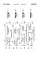
- FIGS. 7, 8, 9, 10, 11, 12, 13 and 14are graphs depicting energy curves generated in response to utility control parameters when applied to a limit controller in accordance with the present invention.
- FIG. 1a utility power generation and distribution system for a plurality of individual consumers in which power from a power generating source 11 is transmitted over line 10 through system load measurement facilities 12 to a plurality of individual load control circuits 13 via line 10'.
- An individual load control circuit 13is located at each customer building or residence, and the power consumed by those circuits is monitored by the system load measurement facility 12 and the information then delivered over line 14 to a load monitoring and dispatch facility 15. Additional information is supplied over line 16 to the facility 15 from the power source 11 relating to the status of the various elements in the power generation facilities, such as, total available power.
- the information from the power source 11 and the system load measurement 12is utilized to make decisions in the monitoring and dispatch facility 15 as to whether the total load on the power source 11 must be decreased or increased and the amount of such decrease or increase.
- decisions, in the form of demand limit increase or decrease signalsare sent to a system signal transmitter 18 which transmits the signals via radio transmitting antenna 19 to a plurality of receiving antennas 20, each antenna 20 transferring the signal via line 21 to a utility signal receiver 22 which is connected via line 23 to one of the load control circuits 13.
- the system signal transmitter 18 and the utility signal receiver 22represent a system that transmits and receives a control signal, such systems could as well be a power line carrier system, a telephone system, a cable system, etc.
- the decisionis made at the dispatch facility 15 that the total load on the power source 11 must or should be reduced by a selected amount, and a command is delivered from the transmitter antenna 19 to each of the receiver antennas 20 to signal each load control circuit 13 to start reducing the load, such reduction based on the energy usage pattern of each customer in a manner to be hereinafter described in more detail.
- one or more signalsmay be delivered by the antenna 19 to each of the receiver antennas 20 to effect the ultimate desired reduction in load on the power source.
- a utilitymay determine through its load monitoring and dispatch facilities 15 that the total load on the power source 11 may be increased, as a result of which signals are delivered via the antenna 19 to effect an increase in load at each load control circuit 13.
- the utility company's objective of reducing the system loadcan be fulfilled with proportionate impact upon each consumer, since in a manner to be described the amount of load reduction is based on the individual consumer's energy usage pattern; and each consumer is subjected to precisely the same utility control signal which will operate to reduce each customer's demand limit by a corresponding percentage of the customer's actual usage of energy preceding the application of the control signal.
- the energy available for each customermay be increased by an equal percentage or rate.
- FIG. 2A preferred form of load control circuit 13 at each customer's location is illustrated in FIG. 2.
- the power which is delivered from the power source 11is applied over two or more power delivery lines 30 and a neutral line 29 for delivery to the circuit 13 and measured by a conventional metering device 31 for utility billing purposes.
- the meter 31is connected to each consumer's main electrical distribution panel 32 which typically comprises a main circuit breaker 33, a plurality of single pole circuit breakers 34, a plurality of double pole circuit breakers 35, and an earth ground terminal block 36.
- a variable limit or adaptive cycle controller 37controls the rate of energy usage in the control circuit 13 and consists of one or more load control switches 38 and a logic circuit 39 which contains the logic necessary to operate the switch 38.
- a voltage reducing transformer 40which may be located external to the controller 37, supplies power at logic voltage levels to the controller 37 via lines 51 and 51'.
- a conventional data display panel 41is connected to the logic circuit 39 via lines 42 and 42' to allow the consumer to monitor the operation of the circuit 13 and to allow utility personnel to modify the operation of the controller 37 for functions related to operational control parameters.
- the logic circuit 39is connected via lines 23 and 23' to a plurality of switch contacts 43 within the receiver 22.
- the contacts 43may open or close in response to a utility control signal to indicate that utility control is active and to instruct the controller to operate in a predetermined manner.
- the length of time that the contacts 43 are actively requesting controlis determined by the length of the peak load that the utility is experiencing and typically may be one to eight hours in duration.
- a plurality of uncontrolled loadsare represented at 44 and are made up of loads which are not under the influence of the controller 37, such as, refrigerators, lighting circuits and small appliances.
- the loads 44are connected to the circuit breakers 34 and 35 by line connections 50 and 50'.
- a plurality of controlled loadsare designated at 45, illustrated in FIG. 2 as an air conditioning system, which are under the influence of the controller 37.
- the air conditioning system 45is merely representative of various controlled loads, such as, heating, cooling and controllable large appliance circuits, and the system or load 45 is connected to the circuit breakers 34 and 35 and routed via lines 46 and 46'.
- Line 46is directed through a high current load switching contactor 55 to the compressor 56 via line 57 as shown.
- the contactor 55is controlled through the load switch 38 of the controller 37 via lines 51' and 54'.
- the load control switches 38are controlled by the logic circuit 39 via line 52.
- lines 46 and 46'deliver power from the circuit breaker 35 to the transformer 40 in order to provide a control circuit for the load 45 and also to energize the controller 37 via lines 51 and 51'.
- the thermostat 53provides a means of controlling the controlled load contactor 55 via lines 54 and 54', the latter being routed through the load switch 38 of the controller 37 to provide a means to interrupt normal operation of the load 45.
- Line 54is also routed to the logic circuit 39 to provide information as to the status of the thermostat 53 and as alternate means for providing power to the logic circuit 39 if required.
- the energy usage of a controlled load 45is measured by the power usage sensor circuit which is in the form of current sensing transformer 48 on the power line 46', and the energy usage information or data is delivered to the logic circuit 39 via line 49.
- the energy usage data thus obtainedis used by the logic circuit 39 to develop an energy usage pattern for loads which vary their energy usage for different ambient conditions.
- an air conditionermay have a variable load either because it has a second stage compressor unit or the speed of the compressor varies with the load required for the ambient conditions.
- the load control circuit 13, as further illustrated in FIG. 3,includes a plurality of relay driver circuits 66 which are controlled via line 65 of the logic circuit 39 to control one or more auxiliary load control switches 58 via line 59.
- Each auxiliary load control switch 58operates in a well-known manner to control auxiliary loads 45, such as, a water heater to obtain greater load reduction.
- a data display and operation selection panel 41is connected via lines 42 and 42' to the logic circuit 39 in order to permit utility personnel to enter operational parameters into memory locations in the logic circuit. Those operational parameters are, for example, percentage reduction levels, temperature control levels or time period selections from which the control signal is generated to initiate adaptive cycling during periods of peak demand.
- a control signalis generated to open the load control switch 38.
- normal operation of the load 45is modified or reduced by an amount or percentage which is correlated with the average run time or energy usage measurements stored in a scratch pad memory 71 to be hereinafter described.
- Relay driver circuit 66which is controlled via line 65 of the logic circuit 39, serves to control an auxiliary controlled load 2 45 by using the auxiliary load control switch 58 which is controlled via line 59.
- the method and frequency of control for auxiliary controlled load 45may be specified and inserted into the logic circuit 39 by means of the data display and operation selection panel 41.
- Line 59' from auxiliary load control switch 58may be used as an additional signal input to the logic circuit 39 or for powering the controller 37.
- the auxiliary load control switch 58represents a more traditional manner of regulating a controlled load 45, designated as "controlled load 2", exclusively in response to a control signal whether from the utility signal receiver 22 or from an internal control signal and is provided herein more for the purpose of illustrating the ability of the load control switch 38 to operate alone or in combination with the auxiliary load control switch 58.
- the utility signal receiver 22provides additional control information to the logic circuit 39 via line 23.
- Utility load monitoring and dispatch 15can monitor system load, and in the case of system peaking, can send a signal to start load reduction via line 17, the system signal transmitter 18 and the antenna 19 to the local antenna 20 and via line 21 to the utility signal receiver 22.
- the load 1 control circuitis made up of the power supply transformer 40, the thermostat 53 and the load switching contactor 55 and provides information on the operation of the controlled load 45; also, it provides a source of power for the logic circuit 39 and a means to control the load by the load control switch 38.
- Line 54 from the thermostat 53provides a signal which tells the logic 39 whether or not the thermostat 53 is requesting load operation and this information is used in determining the natural run time of the load 45.
- Line 54 or 54'also provides a power source to operate the controller 37.
- the contact in the load control switch 38closes to provide the thermostat signal via line 54' to the load 1 control circuit to energize controlled load 1 45.
- the contact in the load control switch 38may open to interrupt the thermostat signal to line 54' to deenergize the load 1 control circuit to provide control of controlled load 1 45.
- an alternate, or secondary, means of collecting additional load power usage informationis provided via line 49 from the power sensor 48 which measures the power usage of controlled load 1 45.
- line 54provides sufficient information to determine the natural run time of the load.
- the power sensor 48provides the information about the energy use of the load so that an optimum control strategy may be determined. In this way, optimum load control is achieved by using a combination of historical control condition data, emergency dispatch via radio signal, thermostat operating interval measurements, and, if the load size is a variable, the energy use of the controlled load.
- a microcontroller 70is interconnected via an internal data buss to program memory 72, scratch pad memory 71, and input/output data ports 73.
- the memory 72contains the program control required to make the processor 70 operate the controller logic circuit 39.
- the scratch pad memory 71is a random access memory used by the microprocessor 70 to store temporary and changing data, such as, energy usage patterns, timing intervals and mathematical results.
- the input/output data ports 73provide digital input information via the inputs to the microprocessor 70 and digital data output information is sent by the microprocessor 70 to control the loads and other circuit functions.
- An oscillator 74defines a high frequency clock source to step the microprocessor 70, and a reset circuit 75 will initialize the logic circuit when power is applied.
- the analog to digital data converter 76converts analog data into binary data for the processor 70.
- the microcontroller 70must perform some of its functions based on real time provided by the real time and nonvolatile memory circuit 77 via input/output data ports 73.
- the real time clock 77derives its time base from the frequency of the time base oscillator 78.
- the nonvolatile memory in circuit 77is used to store operating data parameters.
- the battery 79via the battery control circuit 80, supplies power to maintain the time and nonvolatile data memory during power outages.
- the microcontroller 70controls the battery control circuit 80 to optimize battery life.
- the microcontroller 70is also connected to the data display panel interface 81 with one input line and one output line to receive and send data, respectively, to the optional data display and operation selection panel 41 via lines 42 and 42'.
- the panel 41has an optional output line 90 to the logic power supply 82 to power the logic circuit 39 if it is not otherwise powered.
- the power sensor defined by the current sensing transformer 48inputs the load measuring information signal via line 49 to a power usage interface 83 which scales the signal to a meaningful level for insertion into the analog to digital converter 76.
- the temperature sensor 84also feeds its signals to the temperature interface 85 in scaling the information for insertion into the analog to digital converter 76.
- Utility control signalswhich appear at the contacts 43 of the utility signal receiver 22 are input via line 23 to the input interface 86 which filters the signals and scales the signal level for insertion into the input data port 73 of the device 70.
- the auxiliary load control switch 58may provide via line 59' an additional signal to input interface 86 for insertion into the input data port 73 of the device 70 to further modify controller operation.
- Line 59' of the auxiliary load control switch 38is also routed to the logic power supply 82 where it may be optionally used as an alternative power source for the logic circuit 39.
- the logic power supply 82generates a direct current voltage to operate the controller logic.
- the preferred power source for the logic circuit 39is supplied from the line 46 and applied to the voltage transformer 40 where it is input over line 51 via the thermostat 53 to line 54 and into the logic power supply 82.
- Line 54is also routed to the input interface 86 to supply a signal to the microcontroller 70 via the input/output port 73 to obtain information on the operation of the thermostat 53 which reflects the load requirements and operating pattern of the controlled load 45.
- line 54is routed through the load control contact contained in load control switch 38 to line 54' which completes the path of line 54 back to the control circuitry of load 45.
- the signal from the thermostat 53directly operates load 45 via its contactor 55.
- the signal from the thermostat 53 to the contactor 55is interrupted and the load is controlled by the logic circuit 39.
- the non-volatile memory 87is an integrated circuit which is capable of memory retention when no power is supplied to it, and is used to store parameters including data that the logic generates in case there is a power failure.
- the memory 87preferably includes a signal input/output configuration and therefore sends data to input/output data port 73 as well as receives data and clocking signals from the input/output data port 73.
- the microprocessorsets the output data status on the input/output data port 73 which is directed to the relay driver circuit 66, then to the load control switch 38 via line 52.
- a delay select jumper 89provides a convenient mechanical means for changing a logic operating parameter by changing the position of the jumper to modify data input at the data port 73 of the microcontroller 70.
- NATURAL RUN TIMEThe portion, measured in time, of a fixed time interval in which a load runs at selected operating conditions. For example, an air conditioner may average 20 minutes of run time during 30 minute intervals when the outdoor temperature is in the range of 90° to 95° F., thus establishing a natural run time of 20 minutes.
- FIXED LOADA load which predominantly runs at a constant energy level. For example, a single stage air conditioner which operates at 4 kW.
- VARIABLE LOADA load which operates at two or more fixed energy levels or a load which variably operates between a lower energy level and an upper energy level for the purpose of obtaining the desired output.
- a two stage air conditionerwhich operates at either 4 kW or 8 kW or a variable speed air conditioner which operates between 4 kW and 8 kW.
- USAGE PATTERNA variable length array of energy usage data which is collected by the controller 37 over incremental units of time to obtain a pattern of the energy usage of an appliance. For example, an array which contains energy usage data for sixteen one hour increments.
- ADAPTIVE LOAD VALUEA value which is mathematically derived from the usage pattern of a variable load to fairly represent the data in that pattern. The value derived is used as a basis for calculations during an interval where control is desired. For example, the average of the usage pattern data over sixteen hours may be calculated to obtain a value for the adaptive average.
- the programproceeds to 112; but if they are not active, the program proceeds to 101 where the logic determines weather or not the present time falls during a holiday or is a time previous to a pending control period. If it is not a holiday or if the time is during or after a control period which may occur the program advances to 112; but if a holiday is active or if the time is previous to a control interval the program proceeds to 102 where to logic determines whether or not the temperature measured by temperature sensor 84 is within predetermined limits.
- the programadvances to 112; but if the temperature is within limits the program proceeds to 103 where the logic reads input 54 from the thermostat 53 to determine if the thermostat is requiring the air conditioner to operate because at this point the logic knows that the air conditioner is probably running undisturbed in its natural operating cycle at the temperature range of interest. If the thermostat input is active, the program proceeds to 104 where the logic increments the on time counter to indicate that one minute of run time has occurred; if the thermostat input is inactive, the program proceeds to 105 where the logic increments the off-time counter to indicate that the load has been off for one minute.
- the programcontinues to 106 where the on time and off time counters are summed to determine the size of the combined counters and the program continues to 107 where the sum is compared to a predetermined limit to determine if the quantity of time data is sufficient for further processing. If the data accumulated is not sufficient the program continues at 112; if the data accumulated is sufficient the program continues at 108 where the natural run time is computed from the data in the on time and off time counters. Following 108 the program steps to 109 where the result is compared, and if required adjusted, to predetermined limits to insure that irregularities have not corrupted the result.
- the logicaccesses the usage data stored to determine a value for the natural run time; i.e., the average time a load operates during a predetermined real time interval. In the case shown, the logic sums the array and divides the total by the number of entries in the array to obtain the average and this is stored in the temporary memory 71 for subsequent use as the natural run time value.
- the logic at 111stores the new natural run time value in the memory 87 to preserve it in the event of a power failure which would cause the memory 71 to lose its contents.
- the controller logic 39will collect the operating data and determine the natural run time value. This is the most realistic time to collect usage data because at other times when control is active, has just been active, or the temperature is not within limits, constraints are imposed on the operation of the monitored load such that the operating data may not reflect the true operation patterns.
- the programthen steps to 112 where it would also arrive if any of the prior conditional tests failed and the logic did not follow the previously discussed path.
- the logicdetermines if a control period is active and if not the program steps to 121; if a control period is active the program steps to 113 to determine if the temperature is in the prescribed temperature range for control. If the temperature is not in the control range, the program steps to 121; if the temperature is in the control range, the program steps to 114 where it accesses operational data from memory 87 to determine the preselected control method in which to operate. The program then steps to 115 where the appropriate formulas and operating parameters are retrieved and the calculations are made to determine the off time, the amount of time the controlled load will be locked off, to be used during each control cycle.
- the newly calculated off timeis compared to predetermined limits and adjusted to the limits if required, to assure a realistic value is achieved from the calculations.
- the programthen steps to 117 where input line 54 is again interrogated to see if the thermostat 53 is requiring the load to be on. If the signal on line 54 is not requesting operation, the program steps to 123 where the load switch 38 is deactivated to prevent operation of the controlled load; if the signal on line 54 is requiring the load to be on, the program steps to 118 where the logic decrements a down counter register in memory 71 which is used as a clock to define the control cycle.
- the logicaccesses the preselected cycle period from non-volatile memory 87 and resets the counter to the full cycle period.
- the time remaining on the cycle clockis compared to the newly calculated off time to determine if either the on time or off time interval of the cycle is active. If the cycle count is less than or equal to the calculated off time, the logic steps to 123, which is also the negative route from 117, where the load switch 38 is deactivated to prevent operation of the controlled load; if the cycle count is greater than the calculated off time, the program steps to 120 where the load switch 38 is activated to enable operation of the controlled load.
- a negative route from 112 or 113steps the program to 121 where input line 54 is again interrogated to see if the thermostat 53 is requiring the load to be on. If the signal on line 54 is not requesting operation, the program steps to 123, which is also the negative route from 117 and 119, where the load switch 38 is deactivated to prevent operation of the controlled load; if the signal on line 54 is requiring the load to be on, the program steps to 122 where the cycle clock is decremented and reset if required as described in 118. The cycle clock is decremented in this manner to force the cycle clock to be as random in its cycle as the operation of the controlled load is random in its operation. This precaution leads to a random overall system when many of these controllers compose the system. After operation at 122 the program steps to 120, which is also the positive route from 119, where the load switch 38 is activated to enable operation of the controlled load.
- That part of the program which is applicable to adaptive load cycling of variable load size equipment operationis described by reference to the flow chart of FIG. 6, where the program as represented by the flow chart is entered periodically, such as, on the order of every 60 seconds, by a time based signal generated from the real time clock 77.
- inquiryis made as to whether or not the receiver contacts 43 of the utility signal receiver 22 are active to request utility control. If the contacts are active the program proceeds to 140; but if they are not active, the program proceeds to 131 where the logic determines weather or not the present time falls during a holiday or is a time previous to a pending control period.
- the programadvances to 140; but if a holiday is active or if the time is previous to a control interval the program proceeds to 132 where to logic determines whether or not the temperature measured by temperature sensor 84 is within predetermined limits. If the temperature is not within limits the program advances to 140; but if the temperature is within limits the program proceeds to 133 where the logic reads input 54 from the thermostat 53 to determine if the thermostat is requiring the air conditioner to operate because at this point the logic knows that the air conditioner is probably running undisturbed in its natural operating cycle at the temperature range of interest.
- the programproceeds to 134 where the logic retrieves the one minute average demand in kW from the power usage interface 83 via the analog to digital data converter circuit 76 and the input data port 73.
- the power sensor 48measures the energy usage of the controlled load 45 and supplies the information to the power usage interface 83 via line 49.
- the one minute demand informationis added to previously obtained data to obtain a sum of the demand over a predetermined interval.
- the one minute demandis compared to a data storage location in the memory 87 to determine if a maximum level of demand has been obtained. If so, the old value is replaced with the new value to establish a new maximum demand.
- the programthen steps to 135 where an interval counter is incremented to indicate the interval occurred.
- the logicaccesses the natural demand usage data stored at 77 to determine an average value for the natural demand.
- the logicsums the array and divides the total by the number of entries in the array to obtain the average and this is stored in the temporary memory 71 for subsequent use as the natural run time value.
- the logic at 139stores the new natural demand value in the memory 87 to preserve it in the event of a power failure which would cause the memory 71 to lose its contents.
- the controller logic 39will collect the operating demand data and determine the natural demand value. This is the most realistic time to collect usage data because at other times when control is active, has just been active, or the temperature is not within limits constraints are imposed on the operation of the monitored load such that the operating data may not reflect the true operation patterns.
- the programthen steps to 140 where it would also arrive if any of the prior conditional tests failed and the logic did not follow the previously discussed path.
- the logicdetermines if a control period is active and if not the program steps to 149; if a control period is active the program steps to 141 to determine if the temperature is in the prescribed temperature range for control. If the temperature is not in the control range, the program steps to 149; if the temperature is in the control range, the program steps to 142 where it accesses operational data from memory 87 to determine the preselected control method in which to operate. The program then steps to 143 where the appropriate formulas and operating parameters are retrieved and the calculations are made to determine the off time, the amount of time the controlled load will be locked off, to be used during each control cycle.
- the newly calculated off timeis compared to predetermined limits and adjusted to the limits if required, to assure a realistic value is achieved from the calculations.
- the programthen steps to 145 where input line 54 is again interrogated to see if the thermostat 53 is requiring the load to be on. If the signal on line 54 is not requesting operation, the program steps to 151 where the load switch 38 is deactivated to prevent operation of the controlled load; if the signal on line 54 is requiring the load to be on, the program steps to 146 where the logic decrements a down counter register in memory 71 which is used as a clock to define the control cycle.
- the logicaccesses the preselected cycle period from non-volatile memory 87 and resets the counter to the full cycle period.
- the time remaining on the cycle clockis compared to the newly calculated off time to determine if either the on time or off time interval of the cycle is active. If the cycle count is less than or equal to the calculated off time, the logic steps to 151, which is also the negative route from 145, where the load switch 38 is deactivated to prevent operation of the controlled load; if the cycle count is greater than the calculated off time, the program steps to 148 where the load switch 38 is activated to enable operation of the controlled load.
- a negative route from 140 or 141steps the program to 149 where input line 54 is again interrogated to see if the thermostat 53 is requiring the load to be on. If the signal on line 54 is not requesting operation, the program steps to 151, which is also the negative route from 145 and 147, where the load switch 38 is deactivated to prevent operation of the controlled load; if the signal on line 54 is requiring the load to be on, the program steps to 150 where the cycle clock is decremented and reset if required as described at 146. The cycle clock is decremented in this manner to force the cycle clock to be as random in its cycle as the operation of the controlled load is random in its operation. This precaution leads to a random overall system when many of these controllers compose the system. After operation at 150 the program steps to 148, which is also the positive route from 147, where the load switch 38 is activated to enable operation of the controlled load.
- FIGS. 7 to 10graphically illustrate the effect of adaptive cycling produced by the controller 39 on a controlled load by comparing the results of different control methods on a sample load profile as displayed in FIG. 7.
- FIG. 7represents the idealized on time period 160 and off time period 161 for a fixed load which has had it natural run time calculated by the logic circuit 39.
- FIG. 7indicates that the natural run time for the load is twenty minutes out of a 30 minute interval when the load is allowed to run freely in the temperature range of interest.
- FIGS. 8, 9, and 10show the results of three control methods when control is activated and a 25 percent reduction is specified for each control method.
- FIG. 8shows the results of control by the traditional fixed cycle reduction method where the off time 163 is 7.5 minutes or 25 percent of the overall cycle.
- the fixed cycle reduction methoddoes not create any load reduction because the time the load is held off is less than the time the load normally keeps itself off and the on time 162 may be equal to or greater the value of the natural run time which is 20 minutes.
- FIG. 9shows the results of control when the logic circuit 39 calculates the off time for control by using the natural run time reduction method.
- the 20 minute natural run timeis reduced by 25 percent to yield a reduced on time 164 of 15 minutes.
- the off time 165is then calculated to 15 minutes which is equal to 30 minutes less the selected on time 164 of 15 minutes.
- the natural run time reduction methodreduces the normal run time of the controlled circuit, and thereby the energy usage, by the desired 25 percent.
- FIG. 10shows the results of control when the logic circuit 39 calculates the off time for control by using the total load size reduction method.
- This methodis used when it is desired to reduce the load by a percentage of its full load energy usage, i.e., to reduce the full load of an 8 kW compressor by 25 percent would yield a fixed 2 kW reduction regardless of the average load the compressor might draw. More specifically, if the average load of an 8 kW compressor is 6 kW, the load is reduced by 25 percent of its full load, 2 kW, to make the average load during control periods 4 kW.
- To calculate the off time 167 for this methodconsider the load to be running all of the time so that a 25 percent reduction in operation would yield a 7.5 minute off time. Since the natural off time is 10 minutes, add the 7.5 minutes to the 10 minutes to yield an off time 167 of 17.5 minutes and an on time 166 of 12.5 minutes as shown in FIG. 10.
- FIGS. 11 to 14graphically illustrate the effect of adaptive cycling produced by the controller 39 when a variable demand load is controlled.
- a variable demand loadis a load which operates at various power levels to maintain the desired output.
- FIG. 11shows the load pattern for two types of variable loads which are running freely at the desired load output.
- Line 170represents a load that can vary its usage linearly between a high and low limit.
- Dashed line 171represents a load with two or more discrete power levels. Both lines 170 and 171 also represent a load pattern which has an average energy usage of 5.7 kW during the 30 minute period shown and this energy usage is defined as the natural energy usage of the load and is comparable to the value generated by the logic circuit 39 for this purpose.
- FIGS. 12, 13, and 14show the results of three control methods when control is activated and a 25 percent reduction is specified for each control method.
- FIG. 12shows the results of control by the traditional fixed cycle reduction method where the off time 174 is 7.5 minutes or 25 percent of the overall 30 minute cycle.
- the fixed cycle reduction methoddoes not create any load reduction because variable demand loads increased their demand usage during the allowed on time period to produce the desired output, i.e., the energy usage is still 5.7 kW which is equal to the natural energy usage of 5.7 kW.
- FIG. 13shows the results of control when the logic circuit 39 calculates the off time for control by using the natural energy usage reduction method.
- the natural energy usage reduction methodreduces energy usage of the controlled load by the desired 25 percent as shown by lines 175 and 176.
- FIG. 14shows the results of control when the logic circuit 39 calculates the off time for control by using the total load size reduction method.
- each air conditioner or other variable energy usage deviceis provided with an adaptive load cycler including means responsive to a control signal, either remotely generated or self generated from local time, temperature and humidity measurements.
- the adaptive load cyclerwill monitor and store run times and/or energy use, and compute and store average run times and/or average energy use for specified temperature and humidity ranges.
- the average run times and/or average energy usewill be constantly updated by the adaptive cycler and when a new control signal is received or determined the adaptive cycler will use the latest average received to determine the desired energy or run time reduction.
- the new average established by the adaptive cycleris based on run times or energy use derived from the average run times or energy use over predetermined real time intervals preceding the application of the control signal.
- average use or average run timesmay be established in various ways, such as, measuring the total in a fixed time interval, by integrating the data equation to find an average, differentiating the data equation to find rates of change, or the use of linear regression on the data to predict a trend.
Landscapes
- Engineering & Computer Science (AREA)
- Power Engineering (AREA)
- Air Conditioning Control Device (AREA)
Abstract
Description
Claims (17)
Priority Applications (1)
| Application Number | Priority Date | Filing Date | Title |
|---|---|---|---|
| US08/229,622US5675503A (en) | 1994-04-19 | 1994-04-19 | Adaptive load cycler for controlled reduction of energy use |
Applications Claiming Priority (1)
| Application Number | Priority Date | Filing Date | Title |
|---|---|---|---|
| US08/229,622US5675503A (en) | 1994-04-19 | 1994-04-19 | Adaptive load cycler for controlled reduction of energy use |
Publications (1)
| Publication Number | Publication Date |
|---|---|
| US5675503Atrue US5675503A (en) | 1997-10-07 |
Family
ID=22862019
Family Applications (1)
| Application Number | Title | Priority Date | Filing Date |
|---|---|---|---|
| US08/229,622Expired - Fee RelatedUS5675503A (en) | 1994-04-19 | 1994-04-19 | Adaptive load cycler for controlled reduction of energy use |
Country Status (1)
| Country | Link |
|---|---|
| US (1) | US5675503A (en) |
Cited By (99)
| Publication number | Priority date | Publication date | Assignee | Title |
|---|---|---|---|---|
| US6148623A (en)* | 1998-02-03 | 2000-11-21 | Samsung Electronics Co., Ltd. | System and method for measuring amount of electric power consumption in a refrigerator |
| US6243626B1 (en)* | 1998-10-28 | 2001-06-05 | Bayview Technology Group, Inc. | External power management device with current monitoring precluding shutdown during high current |
| US20020130558A1 (en)* | 2001-03-14 | 2002-09-19 | Wattenburg Willard H. | Method and system to automatically reduce generated power |
| US20030020333A1 (en)* | 2001-07-10 | 2003-01-30 | Yingco Electronic Inc. | System for remotely controlling energy distribution at local sites |
| US20030078698A1 (en)* | 2001-10-19 | 2003-04-24 | Bradford James Alfred | Electrical energy control system |
| US6581396B2 (en) | 1998-10-28 | 2003-06-24 | Bayview Technology Group, Llc | Refrigerated vending machine exploiting expanded temperature variance during power-conservation mode |
| US6636026B1 (en)* | 1999-11-15 | 2003-10-21 | Nikon Corporation | Electric appliance capable of saving power consumption |
| US20040004533A1 (en)* | 2001-07-10 | 2004-01-08 | Jeffrey Ying | Controllable electronic switch with interposable non-conductive element to break circuit path |
| US6684656B2 (en)* | 2002-03-29 | 2004-02-03 | General Electric Company | Low energy appliance control apparatus and method |
| WO2003049248A3 (en)* | 2001-11-30 | 2004-02-12 | Yingco Electronic Inc | System for remotely controlling energy distribution at local sites |
| US20040046455A1 (en)* | 2001-01-16 | 2004-03-11 | Murguia Jose Tomas Ortega | Electrical energy saving system |
| WO2003085798A3 (en)* | 2002-04-01 | 2004-03-18 | Battelle Memorial Institute | Energy management system |
| FR2845531A1 (en)* | 2002-10-08 | 2004-04-09 | Christian Gourmelon | INTEGRAL MANAGEMENT OF ELECTRIC ENERGY BY ASSOCIATION OF AN OPTIMIZER AND A CONTROL AUTOMATE |
| US20040093125A1 (en)* | 2002-11-08 | 2004-05-13 | Bayview Technology Group, Llc | Method and apparatus for power managment control of a compressor-based appliance that reduces electrical power consumption of an appliance |
| US20040112070A1 (en)* | 1998-10-28 | 2004-06-17 | Bayview Technology Group, Llc | Method and apparatus for conserving power consumed by a refrigerated appliance utilizing dispensing event data signals |
| US20040133314A1 (en)* | 2002-03-28 | 2004-07-08 | Ehlers Gregory A. | System and method of controlling an HVAC system |
| US20040164875A1 (en)* | 2003-02-24 | 2004-08-26 | Dischert Lee R. | Method and apparatus for positive control of devices with toggle power control |
| US20040167732A1 (en)* | 2002-01-02 | 2004-08-26 | American Power Conversion Corporation | Method and apparatus for preventing overloads of power distribution networks |
| US6806446B1 (en)* | 2002-10-04 | 2004-10-19 | Stephen D. Neale | Power management controls for electric appliances |
| US6861956B2 (en) | 2001-07-10 | 2005-03-01 | Yingco Electronic Inc. | Remotely controllable wireless energy control unit |
| US20050128043A1 (en)* | 2001-07-10 | 2005-06-16 | Jeffrey Ying | Controllable electronic switch |
| US20050207081A1 (en)* | 2001-07-10 | 2005-09-22 | Jeffrey Ying | System for remotely controlling energy distribution at local sites |
| US20050234604A1 (en)* | 2004-04-19 | 2005-10-20 | Denso Corporation | Onboard-equipment control apparatus and onboard-equipment control system |
| US20060049694A1 (en)* | 2004-09-03 | 2006-03-09 | Lawrence Kates | Method and apparatus for load management in an electric power system |
| US20060111815A1 (en)* | 2002-11-08 | 2006-05-25 | Schanin David J | Method and apparatus for power management control of a cooling system in a consumer accessible appliance |
| US20070021874A1 (en)* | 2005-07-22 | 2007-01-25 | Roger Rognli | Load shedding control for cycled or variable load appliances |
| WO2007037609A1 (en)* | 2005-09-29 | 2007-04-05 | Jeong-Do Lim | Centrally controlled automatic power saving apparatus |
| US20070129850A1 (en)* | 2005-09-07 | 2007-06-07 | Miyaji Wendell M | Local Power Consumption Load Control |
| US20080015742A1 (en)* | 2006-07-11 | 2008-01-17 | Regen Energy Inc. | Method and apparatus for managing an energy consuming load |
| US20090001181A1 (en)* | 2007-06-28 | 2009-01-01 | Honeywell International Inc. | Thermostat with usage history |
| US20090058185A1 (en)* | 2007-08-31 | 2009-03-05 | Optimal Innovations Inc. | Intelligent Infrastructure Power Supply Control System |
| US20090160267A1 (en)* | 2006-06-26 | 2009-06-25 | Lawrence Kates | Method and apparatus for temperature-based load management metering in an electric power system |
| US20090211986A1 (en)* | 2008-02-22 | 2009-08-27 | Lawrence Kates | Method and apparatus for energy-efficient temperature-based systems management |
| US20090216382A1 (en)* | 2008-02-26 | 2009-08-27 | Howard Ng | Direct Load Control System and Method with Comfort Temperature Setting |
| US7595567B1 (en) | 2003-07-08 | 2009-09-29 | Cannon Technologies/Cooper Power | Thermostat device with line under frequency detection and load shedding capability |
| US20090244817A1 (en)* | 2008-04-01 | 2009-10-01 | Moyer Anthony R | Electrical Distribution System |
| US20100010683A1 (en)* | 2008-07-14 | 2010-01-14 | Lawrence Kates | Method and apparatus for power-limiting electrical access |
| US7653443B2 (en) | 2007-03-01 | 2010-01-26 | Daniel Flohr | Methods, systems, circuits and computer program products for electrical service demand management |
| US20100070103A1 (en)* | 2008-09-15 | 2010-03-18 | Aclara Power-Line Systems Inc. | Method for load control using temporal measurements of energy for individual pieces of equipment |
| US20100082176A1 (en)* | 2008-09-26 | 2010-04-01 | Michael Alan Chang | Peer-To-Peer Home Automation Management |
| US7702424B2 (en) | 2003-08-20 | 2010-04-20 | Cannon Technologies, Inc. | Utility load control management communications protocol |
| US20100161148A1 (en)* | 2007-08-28 | 2010-06-24 | Forbes Jr Joseph W | Method and apparatus for actively managing consumption of electric power supplied by an electric utility |
| US20100179704A1 (en)* | 2009-01-14 | 2010-07-15 | Integral Analytics, Inc. | Optimization of microgrid energy use and distribution |
| US20100222935A1 (en)* | 2007-08-28 | 2010-09-02 | Forbes Jr Joseph W | System and method for estimating and providing dispatchable operating reserve energy capacity through use of active load management |
| US20100262311A1 (en)* | 2003-01-21 | 2010-10-14 | Whirlpool Corporation | Process for managing and curtailing power demand of appliances and components thereof, and system using such process |
| GB2472280A (en)* | 2009-07-27 | 2011-02-02 | Rltec Ltd | Monitoring responsive loads connected to electrical power networks |
| US20110029348A1 (en)* | 2008-03-31 | 2011-02-03 | Saffre Fabrice T P | Scheduling usage or provision of resources |
| US20110137436A1 (en)* | 2010-03-23 | 2011-06-09 | Michael Alan Chang | Intelligent gateway for heterogeneous peer-to-peer home automation networks |
| US20110172845A1 (en)* | 2006-07-11 | 2011-07-14 | Regen Energy Inc. | Method and apparatus for managing an energy consuming load |
| US20110172837A1 (en)* | 2007-08-28 | 2011-07-14 | Forbes Jr Joseph W | System and method for estimating and providing dispatchable operating reserve energy capacity through use of active load management |
| US20110172841A1 (en)* | 2007-08-28 | 2011-07-14 | Forbes Jr Joseph W | Method and Apparatus for Actively Managing Consumption of Electric Power Supplied by One or More Electric Utilities |
| US20110172846A1 (en)* | 2006-07-11 | 2011-07-14 | Regen Energy Inc. | Method and apparatus for managing an energy consuming load |
| US20110231028A1 (en)* | 2009-01-14 | 2011-09-22 | Ozog Michael T | Optimization of microgrid energy use and distribution |
| US20110231788A1 (en)* | 2002-05-31 | 2011-09-22 | Whirlpool Corporation | Electronic system for power consumption management of appliances |
| US20110232304A1 (en)* | 2010-03-24 | 2011-09-29 | Whirlpool Corporation | Systems and methods for multi-sense control algorithm for atomizers in refrigerators |
| US20110313588A1 (en)* | 2008-12-15 | 2011-12-22 | Danfoss A/S | Power saving system and method |
| US8131403B2 (en) | 2007-08-28 | 2012-03-06 | Consert, Inc. | System and method for determining and utilizing customer energy profiles for load control for individual structures, devices, and aggregation of same |
| US8145361B2 (en) | 2007-08-28 | 2012-03-27 | Consert, Inc. | System and method for manipulating controlled energy using devices to manage customer bills |
| CN101335454B (en)* | 2001-11-30 | 2012-03-28 | 英科电子有限公司 | System for remotely controlling energy distribution at local sites |
| WO2012051020A1 (en)* | 2010-10-12 | 2012-04-19 | Schneider Electric USA, Inc. | Cycling load controller having a learn mode for automatically determining when the load is turned on and off |
| US8260470B2 (en) | 2007-08-28 | 2012-09-04 | Consert, Inc. | System and method for selective disconnection of electrical service to end customers |
| US20120303987A1 (en)* | 2011-05-27 | 2012-11-29 | Electronics And Telecommunications Research Institute | Energy control apparatus and method using property of electronic device |
| US20130178995A1 (en)* | 2012-01-06 | 2013-07-11 | General Electric Company | Systems, Methods, and Apparatus for Determining Energy Savings |
| WO2013104767A1 (en)* | 2012-01-13 | 2013-07-18 | Sony Corporation | Control system and method for control of electrical devices |
| US8527107B2 (en) | 2007-08-28 | 2013-09-03 | Consert Inc. | Method and apparatus for effecting controlled restart of electrical servcie with a utility service area |
| US20130245841A1 (en)* | 2010-06-26 | 2013-09-19 | Junho AHN | Method for controlling component for network system |
| US8542685B2 (en) | 2007-08-28 | 2013-09-24 | Consert, Inc. | System and method for priority delivery of load management messages on IP-based networks |
| US20130294014A1 (en)* | 2012-05-02 | 2013-11-07 | Server Technology, Inc. | Relay with integrated power sensor |
| US20130338843A1 (en)* | 2012-06-18 | 2013-12-19 | Reza Iravani | Systems, methods and controllers for control of power distribution devices and systems |
| US20140012423A1 (en)* | 2012-07-09 | 2014-01-09 | Guangdong Midea Refrigeration Appliances Co., Ltd. | Energy saving controlling method and device of inverter air-conditioner |
| WO2013104765A3 (en)* | 2012-01-13 | 2014-04-17 | Sony Corporation | Device profile optimization device and method |
| US20140214227A1 (en)* | 2012-12-07 | 2014-07-31 | Battelle Memorial Institute | Method and system for using demand side resources to provide frequency regulation using a dynamic allocation of energy resources |
| US8805552B2 (en) | 2007-08-28 | 2014-08-12 | Causam Energy, Inc. | Method and apparatus for actively managing consumption of electric power over an electric power grid |
| US8806239B2 (en) | 2007-08-28 | 2014-08-12 | Causam Energy, Inc. | System, method, and apparatus for actively managing consumption of electric power supplied by one or more electric power grid operators |
| US8849715B2 (en) | 2012-10-24 | 2014-09-30 | Causam Energy, Inc. | System, method, and apparatus for settlement for participation in an electric power grid |
| US8855279B2 (en) | 2007-08-28 | 2014-10-07 | Consert Inc. | Apparatus and method for controlling communications to and from utility service points |
| JP2014200153A (en)* | 2013-03-29 | 2014-10-23 | 株式会社東芝 | Energy management system, energy management apparatus and energy management method |
| US8890505B2 (en) | 2007-08-28 | 2014-11-18 | Causam Energy, Inc. | System and method for estimating and providing dispatchable operating reserve energy capacity through use of active load management |
| US9130402B2 (en) | 2007-08-28 | 2015-09-08 | Causam Energy, Inc. | System and method for generating and providing dispatchable operating reserve energy capacity through use of active load management |
| US9177323B2 (en) | 2007-08-28 | 2015-11-03 | Causam Energy, Inc. | Systems and methods for determining and utilizing customer energy profiles for load control for individual structures, devices, and aggregation of same |
| US9207698B2 (en) | 2012-06-20 | 2015-12-08 | Causam Energy, Inc. | Method and apparatus for actively managing electric power over an electric power grid |
| US20160091218A1 (en)* | 2014-09-30 | 2016-03-31 | Azbil Corporation | Preference determination apparatus, air conditioning control system, preference determination method and air conditioning control method |
| US9513648B2 (en) | 2012-07-31 | 2016-12-06 | Causam Energy, Inc. | System, method, and apparatus for electric power grid and network management of grid elements |
| US9528717B2 (en) | 2012-02-28 | 2016-12-27 | Cooper Technologies Company | Efficiency heating, ventilating, and air-conditioning through extended run-time control |
| US20160380431A1 (en)* | 2015-06-23 | 2016-12-29 | Sma Solar Technology Ag | Method for controlling a load |
| US9563215B2 (en) | 2012-07-14 | 2017-02-07 | Causam Energy, Inc. | Method and apparatus for actively managing electric power supply for an electric power grid |
| EP1850440B1 (en)* | 2005-02-08 | 2017-07-05 | Kazuo Miwa | Building energy management system |
| US9870593B2 (en) | 2011-12-05 | 2018-01-16 | Hatch Ltd. | System, method and controller for managing and controlling a micro-grid |
| US10122170B2 (en) | 2011-04-11 | 2018-11-06 | Philips Lighting Holding B.V. | Load adjustment sharing system and method |
| US20190020219A1 (en)* | 2017-07-14 | 2019-01-17 | Landis+Gyr Innovations, Inc. | Methods and systems for adaptive load control |
| US10295969B2 (en) | 2007-08-28 | 2019-05-21 | Causam Energy, Inc. | System and method for generating and providing dispatchable operating reserve energy capacity through use of active load management |
| US10310534B2 (en) | 2012-07-31 | 2019-06-04 | Causam Energy, Inc. | System, method, and data packets for messaging for electric power grid elements over a secure internet protocol network |
| US10547178B2 (en) | 2012-06-20 | 2020-01-28 | Causam Energy, Inc. | System and methods for actively managing electric power over an electric power grid |
| US10605474B2 (en) | 2015-07-30 | 2020-03-31 | Encycle Corporation | Smart thermostat orchestration |
| US10768653B2 (en) | 2012-06-20 | 2020-09-08 | Causam Holdings, LLC | System and methods for actively managing electric power over an electric power grid and providing revenue grade data usable for settlement |
| US10861112B2 (en) | 2012-07-31 | 2020-12-08 | Causam Energy, Inc. | Systems and methods for advanced energy settlements, network-based messaging, and applications supporting the same on a blockchain platform |
| US11004160B2 (en) | 2015-09-23 | 2021-05-11 | Causam Enterprises, Inc. | Systems and methods for advanced energy network |
| US11296507B2 (en) | 2017-07-07 | 2022-04-05 | The Board Of Trustees Of The Leland Stanford Junior University | Smart dim fuse: electrical load flexibility controller using sub-circuit voltage modulation and load sensing |
| US12438368B2 (en) | 2007-08-28 | 2025-10-07 | Causam Enterprises, Inc. | System and method for estimating and providing dispatchable operating reserve energy capacity through use of active load management |
Citations (16)
| Publication number | Priority date | Publication date | Assignee | Title |
|---|---|---|---|---|
| US4023043A (en)* | 1974-08-16 | 1977-05-10 | Megatherm Corporation | Computerized peak-shaving system for alleviating electric utility peak loads |
| US4168491A (en)* | 1977-09-29 | 1979-09-18 | Phillips Control Corp. | Energy demand controller and method therefor |
| US4228511A (en)* | 1978-10-06 | 1980-10-14 | General Electric Company | System and method of power demand limiting and temperature control |
| US4337401A (en)* | 1981-01-23 | 1982-06-29 | Honeywell Inc. | Adaptive load shedding |
| US4345162A (en)* | 1980-06-30 | 1982-08-17 | Honeywell Inc. | Method and apparatus for power load shedding |
| US4357665A (en)* | 1979-12-27 | 1982-11-02 | Butler Manufacturing Company | Programmable electronic real-time load controller providing demand limit control |
| US4360881A (en)* | 1980-07-07 | 1982-11-23 | Martinson John R | Energy consumption control system and method |
| US4389577A (en)* | 1982-04-14 | 1983-06-21 | Honeywell Inc. | Apparatus for power load-shedding with auxiliary commandable thermostat |
| US4477733A (en)* | 1982-10-18 | 1984-10-16 | Honeywell Inc. | Temperature dependent duty cycler control system |
| US4819180A (en)* | 1987-02-13 | 1989-04-04 | Dencor Energy Cost Controls, Inc. | Variable-limit demand controller for metering electrical energy |
| US4977715A (en)* | 1988-11-10 | 1990-12-18 | Hochtief Aktiengesellschaft Vorm. Gebr.Helfmann | Reinforced-concrete building element |
| US5017799A (en)* | 1989-06-30 | 1991-05-21 | At&T Bell Laboratories | Automatic power supply load shedding techniques |
| US5107440A (en)* | 1990-08-09 | 1992-04-21 | Pacific Scientific Company | Electrical load management with autogenically transmitted status data |
| US5168170A (en)* | 1989-09-07 | 1992-12-01 | Lexington Power Management Corporation | Subscriber electric power load control system |
| US5184119A (en)* | 1989-07-11 | 1993-02-02 | Alcatel Australia Limited | Unauthorized utility use monitor apparatus and method |
| US5436510A (en)* | 1992-07-03 | 1995-07-25 | Euro Cp S.A.R.L. | Method and a system for globally managing electric power in a network within a dwelling or the like |
- 1994
- 1994-04-19USUS08/229,622patent/US5675503A/ennot_activeExpired - Fee Related
Patent Citations (16)
| Publication number | Priority date | Publication date | Assignee | Title |
|---|---|---|---|---|
| US4023043A (en)* | 1974-08-16 | 1977-05-10 | Megatherm Corporation | Computerized peak-shaving system for alleviating electric utility peak loads |
| US4168491A (en)* | 1977-09-29 | 1979-09-18 | Phillips Control Corp. | Energy demand controller and method therefor |
| US4228511A (en)* | 1978-10-06 | 1980-10-14 | General Electric Company | System and method of power demand limiting and temperature control |
| US4357665A (en)* | 1979-12-27 | 1982-11-02 | Butler Manufacturing Company | Programmable electronic real-time load controller providing demand limit control |
| US4345162A (en)* | 1980-06-30 | 1982-08-17 | Honeywell Inc. | Method and apparatus for power load shedding |
| US4360881A (en)* | 1980-07-07 | 1982-11-23 | Martinson John R | Energy consumption control system and method |
| US4337401A (en)* | 1981-01-23 | 1982-06-29 | Honeywell Inc. | Adaptive load shedding |
| US4389577A (en)* | 1982-04-14 | 1983-06-21 | Honeywell Inc. | Apparatus for power load-shedding with auxiliary commandable thermostat |
| US4477733A (en)* | 1982-10-18 | 1984-10-16 | Honeywell Inc. | Temperature dependent duty cycler control system |
| US4819180A (en)* | 1987-02-13 | 1989-04-04 | Dencor Energy Cost Controls, Inc. | Variable-limit demand controller for metering electrical energy |
| US4977715A (en)* | 1988-11-10 | 1990-12-18 | Hochtief Aktiengesellschaft Vorm. Gebr.Helfmann | Reinforced-concrete building element |
| US5017799A (en)* | 1989-06-30 | 1991-05-21 | At&T Bell Laboratories | Automatic power supply load shedding techniques |
| US5184119A (en)* | 1989-07-11 | 1993-02-02 | Alcatel Australia Limited | Unauthorized utility use monitor apparatus and method |
| US5168170A (en)* | 1989-09-07 | 1992-12-01 | Lexington Power Management Corporation | Subscriber electric power load control system |
| US5107440A (en)* | 1990-08-09 | 1992-04-21 | Pacific Scientific Company | Electrical load management with autogenically transmitted status data |
| US5436510A (en)* | 1992-07-03 | 1995-07-25 | Euro Cp S.A.R.L. | Method and a system for globally managing electric power in a network within a dwelling or the like |
Cited By (258)
| Publication number | Priority date | Publication date | Assignee | Title |
|---|---|---|---|---|
| US6148623A (en)* | 1998-02-03 | 2000-11-21 | Samsung Electronics Co., Ltd. | System and method for measuring amount of electric power consumption in a refrigerator |
| US6243626B1 (en)* | 1998-10-28 | 2001-06-05 | Bayview Technology Group, Inc. | External power management device with current monitoring precluding shutdown during high current |
| US6931869B2 (en) | 1998-10-28 | 2005-08-23 | Usa Technologies, Inc. | Refrigerated vending machine exploiting expanded temperature variance during power-conservation mode |
| US6898942B2 (en) | 1998-10-28 | 2005-05-31 | Usa Technologies, Inc. | Method and apparatus for conserving power consumed by a refrigerated appliance utilizing dispensing event data signals |
| US6581396B2 (en) | 1998-10-28 | 2003-06-24 | Bayview Technology Group, Llc | Refrigerated vending machine exploiting expanded temperature variance during power-conservation mode |
| US20040000154A1 (en)* | 1998-10-28 | 2004-01-01 | Schanin David J. | Refrigerated vending machine exploiting expanded temperature variance during power-conservation mode |
| US20040112070A1 (en)* | 1998-10-28 | 2004-06-17 | Bayview Technology Group, Llc | Method and apparatus for conserving power consumed by a refrigerated appliance utilizing dispensing event data signals |
| US6636026B1 (en)* | 1999-11-15 | 2003-10-21 | Nikon Corporation | Electric appliance capable of saving power consumption |
| US20040046455A1 (en)* | 2001-01-16 | 2004-03-11 | Murguia Jose Tomas Ortega | Electrical energy saving system |
| US7582985B2 (en)* | 2001-01-16 | 2009-09-01 | Murguia Jose Tomas Ortega | Electrical energy saving system |
| US20020130558A1 (en)* | 2001-03-14 | 2002-09-19 | Wattenburg Willard H. | Method and system to automatically reduce generated power |
| US6670728B2 (en)* | 2001-03-14 | 2003-12-30 | The Csu, Chico Research Foundation | Method and system to automatically reduce generated power |
| US7693610B2 (en) | 2001-07-10 | 2010-04-06 | Yingco Electronic Inc. | Remotely controllable wireless energy control unit |
| US10074498B2 (en) | 2001-07-10 | 2018-09-11 | I/O Controls Corporation | Controllable electronic switch |
| US20100013592A1 (en)* | 2001-07-10 | 2010-01-21 | Yingco Electronic Inc. | Controllable electronic switch |
| US7688175B2 (en) | 2001-07-10 | 2010-03-30 | I/O Controls Corporation | Controllable electronic switch |
| US7324876B2 (en) | 2001-07-10 | 2008-01-29 | Yingco Electronic Inc. | System for remotely controlling energy distribution at local sites |
| US20080186126A1 (en)* | 2001-07-10 | 2008-08-07 | Yingco Electronic Inc. | Controllable Electronic Switch |
| US7265652B2 (en) | 2001-07-10 | 2007-09-04 | Yingco Electronic Inc. | Controllable electronic switch |
| US20050128043A1 (en)* | 2001-07-10 | 2005-06-16 | Jeffrey Ying | Controllable electronic switch |
| US7961073B2 (en) | 2001-07-10 | 2011-06-14 | Yingco Electronic Inc. | Controllable electronic switch |
| US20050207081A1 (en)* | 2001-07-10 | 2005-09-22 | Jeffrey Ying | System for remotely controlling energy distribution at local sites |
| US20040004533A1 (en)* | 2001-07-10 | 2004-01-08 | Jeffrey Ying | Controllable electronic switch with interposable non-conductive element to break circuit path |
| US6825750B2 (en) | 2001-07-10 | 2004-11-30 | Yingco Electronic Inc. | Controllable electronic switch with interposable non-conductive element to break circuit path |
| US6832135B2 (en)* | 2001-07-10 | 2004-12-14 | Yingco Electronic Inc. | System for remotely controlling energy distribution at local sites |
| US6861956B2 (en) | 2001-07-10 | 2005-03-01 | Yingco Electronic Inc. | Remotely controllable wireless energy control unit |
| US7925388B2 (en) | 2001-07-10 | 2011-04-12 | Yingco Electronics, Inc. | Remotely controllable wireless energy control unit |
| US20030020333A1 (en)* | 2001-07-10 | 2003-01-30 | Yingco Electronic Inc. | System for remotely controlling energy distribution at local sites |
| US6799091B2 (en)* | 2001-10-19 | 2004-09-28 | James Alfred Bradford | Electrical energy control system |
| US20030078698A1 (en)* | 2001-10-19 | 2003-04-24 | Bradford James Alfred | Electrical energy control system |
| WO2003049248A3 (en)* | 2001-11-30 | 2004-02-12 | Yingco Electronic Inc | System for remotely controlling energy distribution at local sites |
| CN101335454B (en)* | 2001-11-30 | 2012-03-28 | 英科电子有限公司 | System for remotely controlling energy distribution at local sites |
| US20040167732A1 (en)* | 2002-01-02 | 2004-08-26 | American Power Conversion Corporation | Method and apparatus for preventing overloads of power distribution networks |
| US7865272B2 (en) | 2002-01-02 | 2011-01-04 | American Power Conversion Corporation | Method and apparatus for preventing overloads of power distribution networks |
| US20110301773A1 (en)* | 2002-01-02 | 2011-12-08 | American Power Conversion Corporation | Method and apparatus for preventing overloads of power distribution networks |
| US7099784B2 (en)* | 2002-01-02 | 2006-08-29 | American Power Conversion Corporation | Method and apparatus for preventing overloads of power distribution networks |
| US9048688B2 (en)* | 2002-01-02 | 2015-06-02 | Schneider Electric It Corporation | Method and apparatus for preventing overloads of power distribution networks |
| US20070150215A1 (en)* | 2002-01-02 | 2007-06-28 | American Power Conversion Corporation | Method and apparatus for preventing overloads of power distribution networks |
| US7130719B2 (en)* | 2002-03-28 | 2006-10-31 | Robertshaw Controls Company | System and method of controlling an HVAC system |
| US20040133314A1 (en)* | 2002-03-28 | 2004-07-08 | Ehlers Gregory A. | System and method of controlling an HVAC system |
| US6684656B2 (en)* | 2002-03-29 | 2004-02-03 | General Electric Company | Low energy appliance control apparatus and method |
| WO2003085798A3 (en)* | 2002-04-01 | 2004-03-18 | Battelle Memorial Institute | Energy management system |
| US7206670B2 (en) | 2002-04-01 | 2007-04-17 | Battelle Memorial Institute | Energy management system for controlling energy supplied to a set of customer buildings |
| US20050102068A1 (en)* | 2002-04-01 | 2005-05-12 | Pimputkar Sudheer M. | Energy management system |
| US20110231788A1 (en)* | 2002-05-31 | 2011-09-22 | Whirlpool Corporation | Electronic system for power consumption management of appliances |
| US9837820B2 (en) | 2002-05-31 | 2017-12-05 | Whirlpool Corporation | Electronic system for power consumption management of appliances |
| US6806446B1 (en)* | 2002-10-04 | 2004-10-19 | Stephen D. Neale | Power management controls for electric appliances |
| EP1408596A1 (en)* | 2002-10-08 | 2004-04-14 | Christian Gourmelon | Electric energy integral management with optimizer and regulating device |
| FR2845531A1 (en)* | 2002-10-08 | 2004-04-09 | Christian Gourmelon | INTEGRAL MANAGEMENT OF ELECTRIC ENERGY BY ASSOCIATION OF AN OPTIMIZER AND A CONTROL AUTOMATE |
| US7200467B2 (en) | 2002-11-08 | 2007-04-03 | Usa Technologies, Inc. | Method and apparatus for power management control of a cooling system in a consumer accessible appliance |
| US20060111815A1 (en)* | 2002-11-08 | 2006-05-25 | Schanin David J | Method and apparatus for power management control of a cooling system in a consumer accessible appliance |
| US6975926B2 (en)* | 2002-11-08 | 2005-12-13 | Usa Technologies, Inc. | Method and apparatus for power management control of a compressor-based appliance that reduces electrical power consumption of an appliance |
| US20040093125A1 (en)* | 2002-11-08 | 2004-05-13 | Bayview Technology Group, Llc | Method and apparatus for power managment control of a compressor-based appliance that reduces electrical power consumption of an appliance |
| US20100262311A1 (en)* | 2003-01-21 | 2010-10-14 | Whirlpool Corporation | Process for managing and curtailing power demand of appliances and components thereof, and system using such process |
| US20110087382A1 (en)* | 2003-01-21 | 2011-04-14 | Whirlpool Corporation | Process for managing and curtailing power demand of appliances and components thereof |
| US20040164875A1 (en)* | 2003-02-24 | 2004-08-26 | Dischert Lee R. | Method and apparatus for positive control of devices with toggle power control |
| US7595567B1 (en) | 2003-07-08 | 2009-09-29 | Cannon Technologies/Cooper Power | Thermostat device with line under frequency detection and load shedding capability |
| US7702424B2 (en) | 2003-08-20 | 2010-04-20 | Cannon Technologies, Inc. | Utility load control management communications protocol |
| US7869904B2 (en) | 2003-08-20 | 2011-01-11 | Cooper Technologies Company | Utility load control management communications protocol |
| US7680572B2 (en)* | 2004-04-19 | 2010-03-16 | Denso Corporation | Onboard-equipment control apparatus and onboard-equipment control system |
| US20050234604A1 (en)* | 2004-04-19 | 2005-10-20 | Denso Corporation | Onboard-equipment control apparatus and onboard-equipment control system |
| US20060049694A1 (en)* | 2004-09-03 | 2006-03-09 | Lawrence Kates | Method and apparatus for load management in an electric power system |
| EP1850440B1 (en)* | 2005-02-08 | 2017-07-05 | Kazuo Miwa | Building energy management system |
| US20070021874A1 (en)* | 2005-07-22 | 2007-01-25 | Roger Rognli | Load shedding control for cycled or variable load appliances |
| US7528503B2 (en) | 2005-07-22 | 2009-05-05 | Cannon Technologies, Inc. | Load shedding control for cycled or variable load appliances |
| US20070129850A1 (en)* | 2005-09-07 | 2007-06-07 | Miyaji Wendell M | Local Power Consumption Load Control |
| US7606639B2 (en) | 2005-09-07 | 2009-10-20 | Comverge, Inc. | Local power consumption load control |
| WO2007030470A3 (en)* | 2005-09-07 | 2007-11-15 | Comverge Inc | Local power consumption load control |
| WO2007037609A1 (en)* | 2005-09-29 | 2007-04-05 | Jeong-Do Lim | Centrally controlled automatic power saving apparatus |
| US20090160267A1 (en)* | 2006-06-26 | 2009-06-25 | Lawrence Kates | Method and apparatus for temperature-based load management metering in an electric power system |
| US7580775B2 (en)* | 2006-07-11 | 2009-08-25 | Regen Energy Inc. | Method and apparatus for implementing enablement state decision for energy consuming load based on demand and duty cycle of load |
| US20110172845A1 (en)* | 2006-07-11 | 2011-07-14 | Regen Energy Inc. | Method and apparatus for managing an energy consuming load |
| US9703339B2 (en) | 2006-07-11 | 2017-07-11 | Encycle Corporation | Method and apparatus for managing an energy consuming load |
| US10139877B2 (en) | 2006-07-11 | 2018-11-27 | Encycle Corporation | Method and apparatus for managing an energy consuming load |
| US8527108B2 (en) | 2006-07-11 | 2013-09-03 | Regen Energy Inc. | Method and apparatus for managing an energy consuming load |
| US8527109B2 (en) | 2006-07-11 | 2013-09-03 | Regen Energy Inc. | Method and apparatus for managing an energy consuming load |
| US20110172846A1 (en)* | 2006-07-11 | 2011-07-14 | Regen Energy Inc. | Method and apparatus for managing an energy consuming load |
| US8918223B2 (en) | 2006-07-11 | 2014-12-23 | Regen Energy Inc. | Apparatus for managing an energy consuming load |
| US20080015742A1 (en)* | 2006-07-11 | 2008-01-17 | Regen Energy Inc. | Method and apparatus for managing an energy consuming load |
| US7894946B2 (en) | 2006-07-11 | 2011-02-22 | Regen Energy, Inc. | Apparatus for managing an energy consuming load by compiling load state data from other loads |
| US20090287359A1 (en)* | 2006-07-11 | 2009-11-19 | Regen Energy Inc. | Method and apparatus for managing an energy consuming load |
| US9110647B2 (en) | 2006-07-11 | 2015-08-18 | Regen Energy Inc. | Method and apparatus for managing an energy consuming load |
| US7653443B2 (en) | 2007-03-01 | 2010-01-26 | Daniel Flohr | Methods, systems, circuits and computer program products for electrical service demand management |
| US7962248B2 (en) | 2007-03-01 | 2011-06-14 | Daniel Flohr | Methods, systems, circuits, and computer program products for reducing peak electrical demand by shifting activation of electrical appliances |
| US20100125376A1 (en)* | 2007-03-01 | 2010-05-20 | Daniel Flohr | Methods, systems, circuits, and computer program products for reducing peak electrical demand by shifting activation of electrical appliances |
| US20090001181A1 (en)* | 2007-06-28 | 2009-01-01 | Honeywell International Inc. | Thermostat with usage history |
| US8091794B2 (en)* | 2007-06-28 | 2012-01-10 | Honeywell International Inc. | Thermostat with usage history |
| US11108263B2 (en) | 2007-08-28 | 2021-08-31 | Causam Enterprises, Inc. | System and method for estimating and providing dispatchable operating reserve energy capacity through use of active load management |
| US10295969B2 (en) | 2007-08-28 | 2019-05-21 | Causam Energy, Inc. | System and method for generating and providing dispatchable operating reserve energy capacity through use of active load management |
| US20110172837A1 (en)* | 2007-08-28 | 2011-07-14 | Forbes Jr Joseph W | System and method for estimating and providing dispatchable operating reserve energy capacity through use of active load management |
| US11650612B2 (en) | 2007-08-28 | 2023-05-16 | Causam Enterprises, Inc. | Method and apparatus for actively managing consumption of electric power over an electric power grid |
| US8010812B2 (en) | 2007-08-28 | 2011-08-30 | Forbes Jr Joseph W | Method and apparatus for actively managing consumption of electric power supplied by one or more electric utilities |
| US9305454B2 (en) | 2007-08-28 | 2016-04-05 | Consert Inc. | Apparatus and method for controlling communications to and from fixed position communication devices over a fixed bandwidth communication link |
| US11651295B2 (en) | 2007-08-28 | 2023-05-16 | Causam Enterprises, Inc. | Systems and methods for determining and utilizing customer energy profiles for load control for individual structures, devices, and aggregation of same |
| US11733726B2 (en) | 2007-08-28 | 2023-08-22 | Causam Enterprises, Inc. | System, method, and apparatus for actively managing consumption of electric power supplied by one or more electric power grid operators |
| US11119521B2 (en) | 2007-08-28 | 2021-09-14 | Causam Enterprises, Inc. | System, method, and apparatus for actively managing consumption of electric power supplied by one or more electric power grid operators |
| US8032233B2 (en) | 2007-08-28 | 2011-10-04 | Consert Inc. | Method and apparatus for actively managing consumption of electric power supplied by an electric utility |
| US11735915B2 (en) | 2007-08-28 | 2023-08-22 | Causam Enterprises, Inc. | System and method for estimating and providing dispatchable operating reserve energy capacity through use of active load management |
| US9177323B2 (en) | 2007-08-28 | 2015-11-03 | Causam Energy, Inc. | Systems and methods for determining and utilizing customer energy profiles for load control for individual structures, devices, and aggregation of same |
| US9130402B2 (en) | 2007-08-28 | 2015-09-08 | Causam Energy, Inc. | System and method for generating and providing dispatchable operating reserve energy capacity through use of active load management |
| US9069337B2 (en) | 2007-08-28 | 2015-06-30 | Consert Inc. | System and method for estimating and providing dispatchable operating reserve energy capacity through use of active load management |
| US8131403B2 (en) | 2007-08-28 | 2012-03-06 | Consert, Inc. | System and method for determining and utilizing customer energy profiles for load control for individual structures, devices, and aggregation of same |
| US8145361B2 (en) | 2007-08-28 | 2012-03-27 | Consert, Inc. | System and method for manipulating controlled energy using devices to manage customer bills |
| US12422874B2 (en) | 2007-08-28 | 2025-09-23 | Causam Enterprises, Inc. | System, method, and apparatus for actively managing consumption of electric power supplied by one or more electric power grid operators |
| US11025057B2 (en) | 2007-08-28 | 2021-06-01 | Causam Enterprises, Inc. | Systems and methods for determining and utilizing customer energy profiles for load control for individual structures, devices, and aggregation of same |
| US11022995B2 (en) | 2007-08-28 | 2021-06-01 | Causam Enterprises, Inc. | Method and apparatus for actively managing consumption of electric power over an electric power grid |
| US9651973B2 (en) | 2007-08-28 | 2017-05-16 | Causam Energy, Inc. | System and method for estimating and providing dispatchable operating reserve energy capacity through use of active load management |
| US10985556B2 (en) | 2007-08-28 | 2021-04-20 | Causam Energy, Inc. | Systems and methods for determining and utilizing customer energy profiles for load control for individual structures, devices, and aggregation of same |
| US10833504B2 (en) | 2007-08-28 | 2020-11-10 | Causam Energy, Inc. | Systems and methods for determining and utilizing customer energy profiles for load control for individual structures, devices, and aggregation of same |
| US8260470B2 (en) | 2007-08-28 | 2012-09-04 | Consert, Inc. | System and method for selective disconnection of electrical service to end customers |
| US8307225B2 (en) | 2007-08-28 | 2012-11-06 | Consert Inc. | Method and apparatus for actively managing consumption of electric power supplied by one or more electric utilities |
| US8315717B2 (en) | 2007-08-28 | 2012-11-20 | Consert Inc. | Method and apparatus for actively managing consumption of electric power supplied by an electric utility |
| US10394268B2 (en) | 2007-08-28 | 2019-08-27 | Causam Energy, Inc. | Method and apparatus for actively managing consumption of electric power over an electric power grid |
| US10396592B2 (en) | 2007-08-28 | 2019-08-27 | Causam Energy, Inc. | System and method for estimating and providing dispatchable operating reserve energy capacity through use of active load management |
| US8396606B2 (en) | 2007-08-28 | 2013-03-12 | Consert Inc. | System and method for estimating and providing dispatchable operating reserve energy capacity through use of active load management |
| US8996183B2 (en) | 2007-08-28 | 2015-03-31 | Consert Inc. | System and method for estimating and providing dispatchable operating reserve energy capacity through use of active load management |
| US10389115B2 (en) | 2007-08-28 | 2019-08-20 | Causam Energy, Inc. | Systems and methods for determining and utilizing customer energy profiles for load control for individual structures, devices, and aggregation of same |
| US10303194B2 (en) | 2007-08-28 | 2019-05-28 | Causam Energy, Inc | System, method, and apparatus for actively managing consumption of electric power supplied by one or more electric power grid operators |
| US20110172841A1 (en)* | 2007-08-28 | 2011-07-14 | Forbes Jr Joseph W | Method and Apparatus for Actively Managing Consumption of Electric Power Supplied by One or More Electric Utilities |
| US8890505B2 (en) | 2007-08-28 | 2014-11-18 | Causam Energy, Inc. | System and method for estimating and providing dispatchable operating reserve energy capacity through use of active load management |
| US8855279B2 (en) | 2007-08-28 | 2014-10-07 | Consert Inc. | Apparatus and method for controlling communications to and from utility service points |
| US8527107B2 (en) | 2007-08-28 | 2013-09-03 | Consert Inc. | Method and apparatus for effecting controlled restart of electrical servcie with a utility service area |
| US20100222935A1 (en)* | 2007-08-28 | 2010-09-02 | Forbes Jr Joseph W | System and method for estimating and providing dispatchable operating reserve energy capacity through use of active load management |
| US8542685B2 (en) | 2007-08-28 | 2013-09-24 | Consert, Inc. | System and method for priority delivery of load management messages on IP-based networks |
| US10116134B2 (en) | 2007-08-28 | 2018-10-30 | Causam Energy, Inc. | Systems and methods for determining and utilizing customer energy profiles for load control for individual structures, devices, and aggregation of same |
| US12438368B2 (en) | 2007-08-28 | 2025-10-07 | Causam Enterprises, Inc. | System and method for estimating and providing dispatchable operating reserve energy capacity through use of active load management |
| US9899836B2 (en) | 2007-08-28 | 2018-02-20 | Causam Energy, Inc. | Systems and methods for determining and utilizing customer energy profiles for load control for individual structures, devices, and aggregation of same |
| US8700187B2 (en) | 2007-08-28 | 2014-04-15 | Consert Inc. | Method and apparatus for actively managing consumption of electric power supplied by one or more electric utilities |
| US9881259B2 (en) | 2007-08-28 | 2018-01-30 | Landis+Gyr Innovations, Inc. | System and method for estimating and providing dispatchable operating reserve energy capacity through use of active load management |
| US20100179670A1 (en)* | 2007-08-28 | 2010-07-15 | Forbes Jr Joseph W | Method and apparatus for actively managing consumption of electric power supplied by one or more electric utilities |
| US20100161148A1 (en)* | 2007-08-28 | 2010-06-24 | Forbes Jr Joseph W | Method and apparatus for actively managing consumption of electric power supplied by an electric utility |
| US8805552B2 (en) | 2007-08-28 | 2014-08-12 | Causam Energy, Inc. | Method and apparatus for actively managing consumption of electric power over an electric power grid |
| US8806239B2 (en) | 2007-08-28 | 2014-08-12 | Causam Energy, Inc. | System, method, and apparatus for actively managing consumption of electric power supplied by one or more electric power grid operators |
| US20090058185A1 (en)* | 2007-08-31 | 2009-03-05 | Optimal Innovations Inc. | Intelligent Infrastructure Power Supply Control System |
| US20090211986A1 (en)* | 2008-02-22 | 2009-08-27 | Lawrence Kates | Method and apparatus for energy-efficient temperature-based systems management |
| US8014902B2 (en) | 2008-02-22 | 2011-09-06 | Lawrence Kates | Method and apparatus for energy-efficient temperature-based systems management |
| USRE46219E1 (en) | 2008-02-22 | 2016-11-29 | Google Inc. | Method and apparatus for energy-efficient temperature-based systems management |
| US20090216382A1 (en)* | 2008-02-26 | 2009-08-27 | Howard Ng | Direct Load Control System and Method with Comfort Temperature Setting |
| US9679339B2 (en)* | 2008-03-31 | 2017-06-13 | British Telecommunications Public Limited Company | Scheduling usage or provision of resources |
| US20110029348A1 (en)* | 2008-03-31 | 2011-02-03 | Saffre Fabrice T P | Scheduling usage or provision of resources |
| US20090244817A1 (en)* | 2008-04-01 | 2009-10-01 | Moyer Anthony R | Electrical Distribution System |
| US20100010683A1 (en)* | 2008-07-14 | 2010-01-14 | Lawrence Kates | Method and apparatus for power-limiting electrical access |
| US8433452B2 (en)* | 2008-09-15 | 2013-04-30 | Aclara Power-Line Systems, Inc. | Method for load control using temporal measurements of energy for individual pieces of equipment |
| US20100070103A1 (en)* | 2008-09-15 | 2010-03-18 | Aclara Power-Line Systems Inc. | Method for load control using temporal measurements of energy for individual pieces of equipment |
| US20100082176A1 (en)* | 2008-09-26 | 2010-04-01 | Michael Alan Chang | Peer-To-Peer Home Automation Management |
| US8190275B2 (en) | 2008-09-26 | 2012-05-29 | Michael Alan Chang | Peer-to-peer home automation management |
| US20110313588A1 (en)* | 2008-12-15 | 2011-12-22 | Danfoss A/S | Power saving system and method |
| US9263891B2 (en)* | 2008-12-15 | 2016-02-16 | Danfoss A/S | Power saving system and method for a refrigeration system, providing for short term response to reduce ripples on a power grid |
| US8706650B2 (en) | 2009-01-14 | 2014-04-22 | Integral Analytics, Inc. | Optimization of microgrid energy use and distribution |
| US20100179704A1 (en)* | 2009-01-14 | 2010-07-15 | Integral Analytics, Inc. | Optimization of microgrid energy use and distribution |
| US8364609B2 (en) | 2009-01-14 | 2013-01-29 | Integral Analytics, Inc. | Optimization of microgrid energy use and distribution |
| US20110231028A1 (en)* | 2009-01-14 | 2011-09-22 | Ozog Michael T | Optimization of microgrid energy use and distribution |
| US11676079B2 (en) | 2009-05-08 | 2023-06-13 | Causam Enterprises, Inc. | System and method for generating and providing dispatchable operating reserve energy capacity through use of active load management |
| WO2011014073A3 (en)* | 2009-07-27 | 2011-08-18 | Responsive Load Ltd. | Responsive load monitoring system and method |
| GB2473908B (en)* | 2009-07-27 | 2012-05-16 | Responsiveload Ltd | Responsive load monitoring system and method |
| CN102549869A (en)* | 2009-07-27 | 2012-07-04 | 响应负载有限公司 | Responsive load monitoring system and method |
| GB2473908A (en)* | 2009-07-27 | 2011-03-30 | Rltec Ltd | Determining the available level of electrical network response service |
| GB2472280A (en)* | 2009-07-27 | 2011-02-02 | Rltec Ltd | Monitoring responsive loads connected to electrical power networks |
| US20120185108A1 (en)* | 2009-07-27 | 2012-07-19 | Andrew Howe | Responsive Load Monitoring System and Method |
| US8086757B2 (en) | 2010-03-23 | 2011-12-27 | Michael Alan Chang | Intelligent gateway for heterogeneous peer-to-peer home automation networks |
| US20110137436A1 (en)* | 2010-03-23 | 2011-06-09 | Michael Alan Chang | Intelligent gateway for heterogeneous peer-to-peer home automation networks |
| US9004369B2 (en) | 2010-03-24 | 2015-04-14 | Whirlpool Corporation | Systems and methods for multi-sense control algorithm for atomizers in refrigerators |
| US20110232304A1 (en)* | 2010-03-24 | 2011-09-29 | Whirlpool Corporation | Systems and methods for multi-sense control algorithm for atomizers in refrigerators |
| US20130245841A1 (en)* | 2010-06-26 | 2013-09-19 | Junho AHN | Method for controlling component for network system |
| CN103155333A (en)* | 2010-10-12 | 2013-06-12 | 施耐德电气美国股份有限公司 | Cycling load controller having a learn mode for automatically determining when the load is turned on and off |
| WO2012051020A1 (en)* | 2010-10-12 | 2012-04-19 | Schneider Electric USA, Inc. | Cycling load controller having a learn mode for automatically determining when the load is turned on and off |
| CN103155333B (en)* | 2010-10-12 | 2015-10-21 | 施耐德电气美国股份有限公司 | There is the repeated loading controller for automatically determining the mode of learning when load switches on and off |
| US10122170B2 (en) | 2011-04-11 | 2018-11-06 | Philips Lighting Holding B.V. | Load adjustment sharing system and method |
| US20120303987A1 (en)* | 2011-05-27 | 2012-11-29 | Electronics And Telecommunications Research Institute | Energy control apparatus and method using property of electronic device |
| US9870593B2 (en) | 2011-12-05 | 2018-01-16 | Hatch Ltd. | System, method and controller for managing and controlling a micro-grid |
| US9691111B2 (en)* | 2012-01-06 | 2017-06-27 | Aclara Meters Llc | Systems, methods, and apparatus for determining energy savings |
| US20130178995A1 (en)* | 2012-01-06 | 2013-07-11 | General Electric Company | Systems, Methods, and Apparatus for Determining Energy Savings |
| WO2013104767A1 (en)* | 2012-01-13 | 2013-07-18 | Sony Corporation | Control system and method for control of electrical devices |
| WO2013104765A3 (en)* | 2012-01-13 | 2014-04-17 | Sony Corporation | Device profile optimization device and method |
| US9528717B2 (en) | 2012-02-28 | 2016-12-27 | Cooper Technologies Company | Efficiency heating, ventilating, and air-conditioning through extended run-time control |
| US20130294014A1 (en)* | 2012-05-02 | 2013-11-07 | Server Technology, Inc. | Relay with integrated power sensor |
| US20130338843A1 (en)* | 2012-06-18 | 2013-12-19 | Reza Iravani | Systems, methods and controllers for control of power distribution devices and systems |
| US12429894B2 (en) | 2012-06-20 | 2025-09-30 | Causam Enterprises, Inc. | System and methods for actively managing electric power over an electric power grid |
| US11703902B2 (en) | 2012-06-20 | 2023-07-18 | Causam Enterprises, Inc. | System and methods for actively managing electric power over an electric power grid and providing revenue grade data usable for settlement |
| US10088859B2 (en) | 2012-06-20 | 2018-10-02 | Causam Energy, Inc. | Method and apparatus for actively managing electric power over an electric power grid |
| US11899483B2 (en) | 2012-06-20 | 2024-02-13 | Causam Exchange, Inc. | Method and apparatus for actively managing electric power over an electric power grid |
| US11899482B2 (en) | 2012-06-20 | 2024-02-13 | Causam Exchange, Inc. | System and method for actively managing electric power over an electric power grid and providing revenue grade data usable for settlement |
| US12124285B2 (en) | 2012-06-20 | 2024-10-22 | Causam Enterprises, Inc. | System and methods for actively managing electric power over an electric power grid |
| US11228184B2 (en) | 2012-06-20 | 2022-01-18 | Causam Enterprises, Inc. | System and methods for actively managing electric power over an electric power grid |
| US9207698B2 (en) | 2012-06-20 | 2015-12-08 | Causam Energy, Inc. | Method and apparatus for actively managing electric power over an electric power grid |
| US10831223B2 (en) | 2012-06-20 | 2020-11-10 | Causam Energy, Inc. | System and method for actively managing electric power over an electric power grid and providing revenue grade data usable for settlement |
| US11703903B2 (en) | 2012-06-20 | 2023-07-18 | Causam Enterprises, Inc. | Method and apparatus for actively managing electric power over an electric power grid |
| US12210367B1 (en) | 2012-06-20 | 2025-01-28 | Causam Enterprises, Inc. | System and methods for actively managing electric power over an electric power grid |
| US12372993B2 (en) | 2012-06-20 | 2025-07-29 | Causam Enterprises, Inc. | System and methods for actively managing electric power over an electric power grid and providing revenue grade data usable for settlement |
| US10768653B2 (en) | 2012-06-20 | 2020-09-08 | Causam Holdings, LLC | System and methods for actively managing electric power over an electric power grid and providing revenue grade data usable for settlement |
| US12386375B2 (en) | 2012-06-20 | 2025-08-12 | Causam Enterprises, Inc. | Method and apparatus for actively managing electric power over an electric power grid |
| US10547178B2 (en) | 2012-06-20 | 2020-01-28 | Causam Energy, Inc. | System and methods for actively managing electric power over an electric power grid |
| US11262779B2 (en) | 2012-06-20 | 2022-03-01 | Causam Enterprises, Inc. | Method and apparatus for actively managing electric power over an electric power grid |
| US20140012423A1 (en)* | 2012-07-09 | 2014-01-09 | Guangdong Midea Refrigeration Appliances Co., Ltd. | Energy saving controlling method and device of inverter air-conditioner |
| US9062891B2 (en)* | 2012-07-09 | 2015-06-23 | Guangdong Midea Refrigeration Appliances Co., Ltd. | Energy saving controlling method and device of inverter air-conditioner |
| US11126213B2 (en) | 2012-07-14 | 2021-09-21 | Causam Enterprises, Inc. | Method and apparatus for actively managing electric power supply for an electric power grid |
| US11625058B2 (en) | 2012-07-14 | 2023-04-11 | Causam Enterprises, Inc. | Method and apparatus for actively managing electric power supply for an electric power grid |
| US10768654B2 (en) | 2012-07-14 | 2020-09-08 | Causam Energy, Inc. | Method and apparatus for actively managing electric power supply for an electric power grid |
| US10429871B2 (en) | 2012-07-14 | 2019-10-01 | Causam Energy, Inc. | Method and apparatus for actively managing electric power supply for an electric power grid |
| US9563215B2 (en) | 2012-07-14 | 2017-02-07 | Causam Energy, Inc. | Method and apparatus for actively managing electric power supply for an electric power grid |
| US12181904B2 (en) | 2012-07-14 | 2024-12-31 | Causam Enterprises, Inc. | Method and apparatus for actively managing electric power supply for an electric power grid |
| US12061491B2 (en) | 2012-07-14 | 2024-08-13 | Causam Exchange, Inc. | Method and apparatus for actively managing electric power supply for an electric power grid |
| US11782470B2 (en) | 2012-07-14 | 2023-10-10 | Causam Enterprises, Inc. | Method and apparatus for actively managing electric power supply for an electric power grid |
| US10938236B2 (en) | 2012-07-31 | 2021-03-02 | Causam Enterprises, Inc. | System, method, and apparatus for electric power grid and network management of grid elements |
| US11782471B2 (en) | 2012-07-31 | 2023-10-10 | Causam Enterprises, Inc. | System, method, and data packets for messaging for electric power grid elements over a secure internet protocol network |
| US10996706B2 (en) | 2012-07-31 | 2021-05-04 | Causam Enterprises, Inc. | System, method, and data packets for messaging for electric power grid elements over a secure internet protocol network |
| US10998764B2 (en) | 2012-07-31 | 2021-05-04 | Causam Enterprises, Inc. | System, method, and apparatus for electric power grid and network management of grid elements |
| US9513648B2 (en) | 2012-07-31 | 2016-12-06 | Causam Energy, Inc. | System, method, and apparatus for electric power grid and network management of grid elements |
| US12282349B2 (en) | 2012-07-31 | 2025-04-22 | Causam Enterprises, Inc. | System, method, and data packets for messaging for electric power grid elements over a secure internet protocol network |
| US10861112B2 (en) | 2012-07-31 | 2020-12-08 | Causam Energy, Inc. | Systems and methods for advanced energy settlements, network-based messaging, and applications supporting the same on a blockchain platform |
| US11095151B2 (en) | 2012-07-31 | 2021-08-17 | Causam Enterprises, Inc. | System, method, and apparatus for electric power grid and network management of grid elements |
| US10852760B2 (en) | 2012-07-31 | 2020-12-01 | Causam Enterprises, Inc. | System, method, and data packets for messaging for electric power grid elements over a secure internet protocol network |
| US9806563B2 (en) | 2012-07-31 | 2017-10-31 | Causam Energy, Inc. | System, method, and apparatus for electric power grid and network management of grid elements |
| US10651682B2 (en) | 2012-07-31 | 2020-05-12 | Causam Energy, Inc. | System, method, and apparatus for electric power grid and network management of grid elements |
| US12013711B2 (en) | 2012-07-31 | 2024-06-18 | Causam Enterprises, Inc. | System, method, and data packets for messaging for electric power grid elements over a secure internet protocol network |
| US12007802B2 (en) | 2012-07-31 | 2024-06-11 | Causam Enterprises, Inc. | System, method, and apparatus for electric power grid and network management of grid elements |
| US10559976B2 (en) | 2012-07-31 | 2020-02-11 | Causam Energy, Inc. | System, method, and apparatus for electric power grid and network management of grid elements |
| US10985609B2 (en) | 2012-07-31 | 2021-04-20 | Causam Enterprises, Inc. | System, method, and apparatus for electric power grid and network management of grid elements |
| US10429872B2 (en) | 2012-07-31 | 2019-10-01 | Causam Energy, Inc. | System, method, and data packets for messaging for electric power grid elements over a secure internet protocol network |
| US10310534B2 (en) | 2012-07-31 | 2019-06-04 | Causam Energy, Inc. | System, method, and data packets for messaging for electric power grid elements over a secure internet protocol network |
| US11774996B2 (en) | 2012-07-31 | 2023-10-03 | Causam Enterprises, Inc. | System, method, and apparatus for electric power grid and network management of grid elements |
| US11307602B2 (en) | 2012-07-31 | 2022-04-19 | Causam Enterprises, Inc. | System, method, and data packets for messaging for electric power grid elements over a secure internet protocol network |
| US11316367B2 (en) | 2012-07-31 | 2022-04-26 | Causam Enterprises, Inc. | System, method, and apparatus for electric power grid and network management of grid elements |
| US11501389B2 (en) | 2012-07-31 | 2022-11-15 | Causam Enterprises, Inc. | Systems and methods for advanced energy settlements, network-based messaging, and applications supporting the same on a blockchain platform |
| US11561565B2 (en) | 2012-07-31 | 2023-01-24 | Causam Enterprises, Inc. | System, method, and data packets for messaging for electric power grid elements over a secure internet protocol network |
| US11561564B2 (en) | 2012-07-31 | 2023-01-24 | Causam Enterprises, Inc. | System, method, and apparatus for electric power grid and network management of grid elements |
| US11747849B2 (en) | 2012-07-31 | 2023-09-05 | Causam Enterprises, Inc. | System, method, and apparatus for electric power grid and network management of grid elements |
| US10320227B2 (en) | 2012-07-31 | 2019-06-11 | Causam Energy, Inc. | System, method, and apparatus for electric power grid and network management of grid elements |
| US10523050B2 (en) | 2012-07-31 | 2019-12-31 | Causam Energy, Inc. | System, method, and apparatus for electric power grid and network management of grid elements |
| US11650613B2 (en) | 2012-07-31 | 2023-05-16 | Causam Enterprises, Inc. | System, method, and apparatus for electric power grid and network management of grid elements |
| US10381870B2 (en) | 2012-07-31 | 2019-08-13 | Causam Energy, Inc. | System, method, and apparatus for electric power grid and network management of grid elements |
| US11681317B2 (en) | 2012-07-31 | 2023-06-20 | Causam Enterprises, Inc. | System, method, and data packets for messaging for electric power grid elements over a secure internet protocol network |
| US11263710B2 (en) | 2012-10-24 | 2022-03-01 | Causam Exchange, Inc. | System, method, and apparatus for settlement for participation in an electric power grid |
| US8849715B2 (en) | 2012-10-24 | 2014-09-30 | Causam Energy, Inc. | System, method, and apparatus for settlement for participation in an electric power grid |
| US10497074B2 (en) | 2012-10-24 | 2019-12-03 | Causam Energy, Inc. | System, method, and apparatus for settlement for participation in an electric power grid |
| US10521868B2 (en) | 2012-10-24 | 2019-12-31 | Causam Energy, Inc. | System, method, and apparatus for settlement for participation in an electric power grid |
| US10529037B2 (en) | 2012-10-24 | 2020-01-07 | Causam Energy, Inc. | System, method, and apparatus for settlement for participation in an electric power grid |
| US10497073B2 (en) | 2012-10-24 | 2019-12-03 | Causam Energy, Inc. | System, method, and apparatus for settlement for participation in an electric power grid |
| US11288755B2 (en) | 2012-10-24 | 2022-03-29 | Causam Exchange, Inc. | System, method, and apparatus for settlement for participation in an electric power grid |
| US11270392B2 (en) | 2012-10-24 | 2022-03-08 | Causam Exchange, Inc. | System, method, and apparatus for settlement for participation in an electric power grid |
| US11798103B2 (en) | 2012-10-24 | 2023-10-24 | Causam Exchange, Inc. | System, method, and apparatus for settlement for participation in an electric power grid |
| US11803921B2 (en) | 2012-10-24 | 2023-10-31 | Causam Exchange, Inc. | System, method, and apparatus for settlement for participation in an electric power grid |
| US11816744B2 (en) | 2012-10-24 | 2023-11-14 | Causam Exchange, Inc. | System, method, and apparatus for settlement for participation in an electric power grid |
| US11823292B2 (en) | 2012-10-24 | 2023-11-21 | Causam Enterprises, Inc. | System, method, and apparatus for settlement for participation in an electric power grid |
| US11195239B2 (en) | 2012-10-24 | 2021-12-07 | Causam Enterprises, Inc. | System, method, and apparatus for settlement for participation in an electric power grid |
| US20170104331A1 (en)* | 2012-12-07 | 2017-04-13 | Battelle Memorial Institute | Method and system for using demand side resources to provide frequency regulation using a dynamic allocation of energy resources |
| US9997915B2 (en)* | 2012-12-07 | 2018-06-12 | Battelle Memorial Institute | Method and system for using demand side resources to provide frequency regulation using a dynamic allocation of energy resources |
| US20140214227A1 (en)* | 2012-12-07 | 2014-07-31 | Battelle Memorial Institute | Method and system for using demand side resources to provide frequency regulation using a dynamic allocation of energy resources |
| US9537313B2 (en)* | 2012-12-07 | 2017-01-03 | Battelle Memorial Institute | Method and system for using demand side resources to provide frequency regulation using a dynamic allocation of energy resources |
| JP2014200153A (en)* | 2013-03-29 | 2014-10-23 | 株式会社東芝 | Energy management system, energy management apparatus and energy management method |
| US20160091218A1 (en)* | 2014-09-30 | 2016-03-31 | Azbil Corporation | Preference determination apparatus, air conditioning control system, preference determination method and air conditioning control method |
| US10103543B2 (en)* | 2015-06-23 | 2018-10-16 | Sma Solar Technology Ag | Method for controlling a load |
| US20160380431A1 (en)* | 2015-06-23 | 2016-12-29 | Sma Solar Technology Ag | Method for controlling a load |
| US10605474B2 (en) | 2015-07-30 | 2020-03-31 | Encycle Corporation | Smart thermostat orchestration |
| US11004160B2 (en) | 2015-09-23 | 2021-05-11 | Causam Enterprises, Inc. | Systems and methods for advanced energy network |
| US11296507B2 (en) | 2017-07-07 | 2022-04-05 | The Board Of Trustees Of The Leland Stanford Junior University | Smart dim fuse: electrical load flexibility controller using sub-circuit voltage modulation and load sensing |
| US20190020219A1 (en)* | 2017-07-14 | 2019-01-17 | Landis+Gyr Innovations, Inc. | Methods and systems for adaptive load control |
| US10727691B2 (en)* | 2017-07-14 | 2020-07-28 | Landis+Gyr Innovations, Inc. | Methods and systems for adaptive load control |
Similar Documents
| Publication | Publication Date | Title |
|---|---|---|
| US5675503A (en) | Adaptive load cycler for controlled reduction of energy use | |
| US4819180A (en) | Variable-limit demand controller for metering electrical energy | |
| US8897923B2 (en) | Achieving energy demand response using price signals and a load control transponder | |
| US5414640A (en) | Method and apparatus for adaptive demand limiting electric consumption through load shedding | |
| EP0191801B1 (en) | Residential heating, cooling and energy management system | |
| US7992630B2 (en) | System and method for pre-cooling of buildings | |
| US4909041A (en) | Residential heating, cooling and energy management system | |
| US5274571A (en) | Energy storage scheduling system | |
| US7830037B2 (en) | Grid stabilising system | |
| CN101809521B (en) | Load management thermostat | |
| CA2765674C (en) | Water heater demand side management system | |
| US4551812A (en) | Energy controller and method for dynamic allocation of priorities of controlled load curtailment to ensure adequate load sharing | |
| TWI441407B (en) | Method and apparatus for allocating electrical energy and computer-readable | |
| EP1330007B1 (en) | Demand control apparatus and power distribution control system | |
| EP1025474B1 (en) | Environmental condition control and energy-management system and method | |
| US7039532B2 (en) | Method and apparatus for reading and controlling utility consumption | |
| US7177728B2 (en) | System and methods for maintaining power usage within a set allocation | |
| US4685307A (en) | Residential heating, cooling and energy management system | |
| US20090018706A1 (en) | Flexible electric load management system and method therefore | |
| US20070203860A1 (en) | Energy budget manager | |
| US20050102068A1 (en) | Energy management system | |
| KR20120086979A (en) | Electrical apparatus, power manager, power management system having same, and control method thereof | |
| JP2003125535A (en) | Electricity unit price change system based on demand measurement | |
| US20190215181A1 (en) | Method of demand side management control for electric appliances | |
| AU2012201017A1 (en) | Energy budget manager |
Legal Events
| Date | Code | Title | Description |
|---|---|---|---|
| AS | Assignment | Owner name:DENCOR ENERGY COST CONTROLS, INC., COLORADO Free format text:ASSIGNMENT OF ASSIGNORS INTEREST;ASSIGNORS:MOE, MAYNARD L.;HEDMAN, THEODORE A.;REEL/FRAME:006982/0584 Effective date:19940413 | |
| FPAY | Fee payment | Year of fee payment:4 | |
| REMI | Maintenance fee reminder mailed | ||
| FPAY | Fee payment | Year of fee payment:8 | |
| SULP | Surcharge for late payment | Year of fee payment:7 | |
| FEPP | Fee payment procedure | Free format text:PAYOR NUMBER ASSIGNED (ORIGINAL EVENT CODE: ASPN); ENTITY STATUS OF PATENT OWNER: SMALL ENTITY Free format text:PAYER NUMBER DE-ASSIGNED (ORIGINAL EVENT CODE: RMPN); ENTITY STATUS OF PATENT OWNER: SMALL ENTITY | |
| FEPP | Fee payment procedure | Free format text:PAYOR NUMBER ASSIGNED (ORIGINAL EVENT CODE: ASPN); ENTITY STATUS OF PATENT OWNER: SMALL ENTITY Free format text:PAYER NUMBER DE-ASSIGNED (ORIGINAL EVENT CODE: RMPN); ENTITY STATUS OF PATENT OWNER: SMALL ENTITY | |
| REMI | Maintenance fee reminder mailed | ||
| LAPS | Lapse for failure to pay maintenance fees | ||
| STCH | Information on status: patent discontinuation | Free format text:PATENT EXPIRED DUE TO NONPAYMENT OF MAINTENANCE FEES UNDER 37 CFR 1.362 | |
| FP | Lapsed due to failure to pay maintenance fee | Effective date:20091007 |