US5675473A - Apparatus and method for shielding an electronic module from electromagnetic radiation - Google Patents
Apparatus and method for shielding an electronic module from electromagnetic radiationDownload PDFInfo
- Publication number
- US5675473A US5675473AUS08/606,316US60631696AUS5675473AUS 5675473 AUS5675473 AUS 5675473AUS 60631696 AUS60631696 AUS 60631696AUS 5675473 AUS5675473 AUS 5675473A
- Authority
- US
- United States
- Prior art keywords
- fluid
- compartment
- nozzle
- cover
- communication
- Prior art date
- Legal status (The legal status is an assumption and is not a legal conclusion. Google has not performed a legal analysis and makes no representation as to the accuracy of the status listed.)
- Expired - Fee Related
Links
- 230000005670electromagnetic radiationEffects0.000titleclaimsdescription16
- 238000000034methodMethods0.000titleclaimsdescription10
- 239000012530fluidSubstances0.000claimsabstractdescription121
- 239000007921spraySubstances0.000claimsabstractdescription26
- 238000004891communicationMethods0.000claimsabstractdescription22
- 239000000463materialSubstances0.000claimsabstractdescription21
- 238000001816coolingMethods0.000claimsdescription21
- 239000002184metalSubstances0.000claimsdescription5
- 229910052751metalInorganic materials0.000claimsdescription5
- 238000007599dischargingMethods0.000claimsdescription3
- 229910001369BrassInorganic materials0.000claimsdescription2
- 239000010951brassSubstances0.000claimsdescription2
- 239000002131composite materialSubstances0.000claimsdescription2
- 239000002826coolantSubstances0.000description17
- 239000007788liquidSubstances0.000description8
- 238000000429assemblyMethods0.000description3
- 230000000712assemblyEffects0.000description3
- 230000002829reductive effectEffects0.000description3
- OKTJSMMVPCPJKN-UHFFFAOYSA-NCarbonChemical compound[C]OKTJSMMVPCPJKN-UHFFFAOYSA-N0.000description2
- XEEYBQQBJWHFJM-UHFFFAOYSA-NIronChemical compound[Fe]XEEYBQQBJWHFJM-UHFFFAOYSA-N0.000description2
- 229910052799carbonInorganic materials0.000description2
- 238000000465mouldingMethods0.000description2
- 238000004806packaging method and processMethods0.000description2
- 238000011160researchMethods0.000description2
- 238000005476solderingMethods0.000description2
- 230000005534acoustic noiseEffects0.000description1
- 230000002238attenuated effectEffects0.000description1
- 230000033228biological regulationEffects0.000description1
- 238000005219brazingMethods0.000description1
- 239000004020conductorSubstances0.000description1
- 239000000356contaminantSubstances0.000description1
- 230000003247decreasing effectEffects0.000description1
- 238000013461designMethods0.000description1
- 239000000428dustSubstances0.000description1
- 230000008030eliminationEffects0.000description1
- 238000003379elimination reactionMethods0.000description1
- 238000011156evaluationMethods0.000description1
- 238000001704evaporationMethods0.000description1
- 230000008020evaporationEffects0.000description1
- 230000005484gravityEffects0.000description1
- 230000017525heat dissipationEffects0.000description1
- 238000001746injection mouldingMethods0.000description1
- 229910052742ironInorganic materials0.000description1
- 239000007791liquid phaseSubstances0.000description1
- 238000004519manufacturing processMethods0.000description1
- 239000007769metal materialSubstances0.000description1
- 238000001465metallisationMethods0.000description1
- 150000002739metalsChemical class0.000description1
- 239000000203mixtureSubstances0.000description1
- 238000012986modificationMethods0.000description1
- 230000004048modificationEffects0.000description1
- 239000002991molded plasticSubstances0.000description1
- 239000003973paintSubstances0.000description1
- 230000036961partial effectEffects0.000description1
- 238000007747platingMethods0.000description1
- 239000004417polycarbonateSubstances0.000description1
- 229920000515polycarbonatePolymers0.000description1
- 230000001681protective effectEffects0.000description1
- 239000011347resinSubstances0.000description1
- 229920005989resinPolymers0.000description1
- 238000007789sealingMethods0.000description1
- 238000005507sprayingMethods0.000description1
- 238000012360testing methodMethods0.000description1
- TXEYQDLBPFQVAA-UHFFFAOYSA-NtetrafluoromethaneChemical compoundFC(F)(F)FTXEYQDLBPFQVAA-UHFFFAOYSA-N0.000description1
- 230000008646thermal stressEffects0.000description1
- 238000012546transferMethods0.000description1
- 238000007740vapor depositionMethods0.000description1
- 238000003466weldingMethods0.000description1
Images


Classifications
- H—ELECTRICITY
- H05—ELECTRIC TECHNIQUES NOT OTHERWISE PROVIDED FOR
- H05K—PRINTED CIRCUITS; CASINGS OR CONSTRUCTIONAL DETAILS OF ELECTRIC APPARATUS; MANUFACTURE OF ASSEMBLAGES OF ELECTRICAL COMPONENTS
- H05K9/00—Screening of apparatus or components against electric or magnetic fields
- H05K9/0007—Casings
- H05K9/002—Casings with localised screening
- H05K9/0022—Casings with localised screening of components mounted on printed circuit boards [PCB]
- H05K9/0037—Housings with compartments containing a PCB, e.g. partitioning walls
- H—ELECTRICITY
- H05—ELECTRIC TECHNIQUES NOT OTHERWISE PROVIDED FOR
- H05K—PRINTED CIRCUITS; CASINGS OR CONSTRUCTIONAL DETAILS OF ELECTRIC APPARATUS; MANUFACTURE OF ASSEMBLAGES OF ELECTRICAL COMPONENTS
- H05K9/00—Screening of apparatus or components against electric or magnetic fields
Definitions
- This inventionrelates generally to the shielding of electronic modules, and, more particularly, to an apparatus and method for shielding an electronic module from electromagnetic radiation.
- Heat-generating electronic modulessuch as multi-chip modules, electronic hybrid assemblies such as power amplifiers and passive components such as filters are susceptible to electromagnetic interference (EMI) during operation.
- electronic modules operating in high-frequency environmentssuch as radio frequency communication systems may themselves be sources of undesirable electromagnetic radiation.
- Electromagnetic radiationmay be diverted to ground using protective enclosures such as shields. Shielded electronic modules, like other electronic modules, generally require cooling during operation.
- shielded electronic modulesare cooled by natural or forced air convection which, because of relatively poor thermal capacitance and heat transfer coefficients, requires moving large volumes of air through spaces between the module and its shield or past a heavy heat sink attached to the module.
- air-cooled modulesare generally quite large. Further, the air cooling process itself may introduce undesired acoustic noise and contaminants such as dust into the module. Still further, passing air through module shields may require openings in the shields through which not only air but also undesirable electromagnetic radiation may pass.
- Evaporative spray coolingfeatures the spraying of atomized liquid droplets directly onto a surface of a heat-producing device such as an electronic module.
- a thin liquid filmcoats the module, and heat is removed primarily by evaporation of the liquid from the module's surface.
- evaporative spray coolingis a preferred method of heat removal in many electronics applications
- known spray cooling systemsare not specifically designed to cool EMI-shielded electronic modules.
- an apparatus for shielding an electronic module from electromagnetic radiationwhich includes a cover having a first surface and a second surface opposed to the first surface.
- the second surfacehas an edge defining a perimeter and has a recessed region.
- a wallis in communication with the recessed region, the wall and at least a portion of the edge define a compartment.
- An electromagnetic interference-attenuating materialis disposed in the compartment, and a fluid distributing manifold is disposed in the cover.
- a nozzle housing sized to receive a nozzleis located in the fluid distributing manifold.
- the nozzle housinghas a receptacle end and a spray end. The spray end has an aperture in communication with the compartment and the receptacle end is in communication with the fluid distributing manifold.
- an apparatus for spray-cooling a shielded electronic moduleincludes a housing having a wall disposed in the housing.
- the walldefines a first compartment and a second compartment.
- An electromagnetic interference (EMI)-attenuating materialis in communication with the wall.
- a nozzleis disposed in the first compartment, to receive and atomize a fluid and to discharge the atomized fluid into the first compartment.
- EMIelectromagnetic interference
- a method for spray-cooling a shielded electronic moduleincludes providing a cover having a first surface and a second surface opposed to the first surface, the second surface having an edge defining a perimeter and having a recessed region, the recessed region having a wall disposed therein, the wall and at least a portion of the edge defining a compartment;
- EMI-attenuating materialto at least a portion of the compartment; supplying a fluid to a fluid distributing manifold formed in the cover; receiving the fluid by a nozzle disposed in the fluid distributing manifold, the nozzle having a spray end in communication with the compartment and an aperture disposed at a tip of the spray end; atomizing the fluid by the spray end of the nozzle; and discharging the atomized fluid into the compartment via the aperture.
- FIG. 1is a perspective view of a top side of an apparatus for shielding an electronic module from electromagnetic radiation according to a first embodiment of the present invention.
- FIG. 2is a partial perspective view of a bottom side of the apparatus shown in FIG. 1.
- FIG. 3is a side view of a nozzle housing for spray-cooling a shielded electronic module as shown in FIGS. 1 and 2.
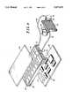
- FIG. 4is an expanded perspective view illustrating a closed loop fluid flow for the apparatus shown in FIGS. 1 and 2.
- FIG. 5is a perspective view of an apparatus for shielding an electronic module from electromagnetic radiation according to a second embodiment of the present invention.
- FIGS. 1 and 2are perspective views of a top and a bottom, respectively, of an apparatus for shielding an electronic module from electromagnetic radiation according to a first embodiment of the present invention.
- a cover 10which is preferably molded plastic such as a polycarbonate but may be another material such as metal, has a top surface 12 and a bottom surface 14 opposed to top surface 12.
- bottom surface 14has an edge 16 defining a perimeter of bottom surface 14.
- Bottom surface 14also has a region 18 which is recessed relative to edge 16.
- One or more walls 20are disposed in, and substantially perpendicular to, recessed region 18 of bottom surface 14. A number of walls 20 are shown. One or more walls 20 and at least a portion of edge 16 define one or more compartments 22. A number of compartments are depicted in FIG. 2. It is contemplated that compartments 22 may be of any geometrical shape. For example, a linear wall extending from one side of recessed region 18 to another side of recessed region 18 and the portions of edges 16 to either side of the linear wall may form two rectangular compartments.
- An electromagnetic interference (EMI)-attenuating material 24such as metal, suitable metals being well-known and widely available, is formed in at least one compartment 22. Carbon, iron and the like may also be used as EMI-attenuating materials. EMI-attenuating material 24 shields compartment 22 to a certain degree from electromagnetic radiation. Compartments 22 treated with EMI-attenuating material 24 surround electronic modules (not shown), so that the electronic modules or parts thereof are isolated (to the extent practicable) from generating or receiving EMI.
- EMIelectromagnetic interference
- cover 10After conventionally molding cover 10, metallization of compartments 22 may proceed according to any number of well-known methods, such as compliant conductive material overmolding, vapor-deposition, metal-plating or application of conductive paints.
- cover 10may be a composite structure, comprising, for example, a resin and an EMI-attenuating material such as metal, carbon or another suitable material.
- Compartments 22are preferably grounded or otherwise electrically connected to electronic modules to divert undesired electromagnetic radiation to ground.
- a conductive gasketmay be used to provide an electrical connection between compartments 22 and electronic modules.
- each fluid distributing manifold 26includes a recessed surface 408 which opposes a specific compartment 22.
- Fluid distributing manifolds 26 of different geometrical cross-sectionsmay be formed in various ways in cover 10.
- fluid distributing manifolds 26may have circular, conical or rectangular cross-sections.
- Manifolds 26may be grooves formed in top surface 12 of cover 10, or may be separately-formed conduits disposed inside of cover 10.
- a fluid collecting conduit 28which is formed from a number of interconnected fluid paths may also be disposed in cover 10. Fluid collecting conduit 28 connects top surface 12 and bottom surface 14 of cover 10, and is preferably located adjacent to at least a portion of a perimeter of each compartment 22.
- At least one nozzle housing 30is disposed in each fluid distributing manifold 26. As shown in detail in FIG. 3, nozzle housing 30 has a receptacle end 32 which is disposed on a fluid distributing manifold (shown in FIG. 1). A spray end 34 of nozzle housing 30 is in communication with a compartment 22 (shown in FIG. 2), and includes an aperture 36, on the order of 0.15 mm in diameter.
- Each nozzle housing 30is sized to receive a nozzle 500. It is contemplated that a nozzle is secured to a nozzle housing 30 by, for example, press-fitting, soldering or bonding. Alternatively, a nozzle may be integrally formed in each fluid distributing manifold.
- Nozzlesare preferably miniature atomizers such as simplex pressure-swirl atomizers, which are approximately 0.3 mm high and which may be made of any suitable material.
- An example of a suitable materialis a metallic material such as brass.
- Simplex pressure-swirl atomizersare described in detail in U.S. Pat. No. 5,220,804 to Tilton et al., incorporated herein by reference, and are commercially available from Isothermal Systems Research, Inc., located in Colton, Wash.
- each fluid distributing manifold 26receives a coolant (not shown) from fluid inlet port 60 and supplies the coolant to receptacle end 32 of one or more nozzle housings 30 which are fitted with nozzles (not shown).
- the nozzlesatomize the coolant and discharge the atomized fluid 40 through aperture 36 into one or more compartments 22 opposing fluid distributing manifolds 26.
- Fluid 40may be discharged from aperture 36 at a substantially perpendicular angle to recessed region 18, collected via the action of negative pressure by fluid collecting conduit 28 (discussed further in connection with FIG. 4) and removed via fluid outlet port 62.
- the coolantis preferably FluorinertTM, available from 3M, order number FC-72, but may be another suitable dielectric coolant, such liquids being well-known and widely available.
- a perfluorocarbon liquid chemically similar to FluorinertTMis available from Ausimont Galden®.
- compartments 22electronic modules shielded from EMI by compartments 22 are individually spray-cooled according to each module's needs.
- An electronic module located in a compartment 22 having a power density of up to three-hundred Watts per square centimeteris effectively cooled.
- the removal of heat directly from individual electronic moduleshelps to reduce operating temperatures of the modules and their associated components, increasing reliability through elimination of thermal variation and associated thermal stresses.
- Fluid inlet and outlet ports 60, 62unlike air holes, are remotely locatable from electronic modules, and have very small diameters relative to their lengths. Thus, high frequency electromagnetic waves which would contribute to EMI are significantly reduced.
- Cover 10may be placed as close to a surface of an electronic module as the heights of components attached to the module will allow, resulting in compact module packaging. And unlike air cooling, which is most effective when heat is spread over a large area, for example, a large heat sink, spray cooling encourages heat concentration, another factor contributing to reduced package volume and weight
- a plate 44may be attached and sealed to top surface 12 of cover 10.
- gas-assist injection moldingto manufacture plate 44 and cover 10 as an integral part, forming internal voids during the molding process.
- a fluid supply manifold(discussed in connection with FIG. 5) may be attached and sealed to a perimeter of top surface
- Another plate 46which may be, among other things, a printed circuit board, has one or more electronic modules 45 attached thereto.
- Plate 46is fastened to at least a portion of edge 16 (shown in FIG. 2) by any suitable means.
- Electronic modules 45 (or parts thereof) on plate 46are positioned so that a compartment 22 (shown in FIG. 2), which has been treated with, or is in part comprised of, an EMI-attenuating material, surrounds one or more modules 45.
- a connector 47provides electrical connections for electronic modules 45.
- Shielded modules 45 on plate 46may be placed in a rack-type housing such as a Versa Module Europe (VME) cage or an Electronic Industries Association (EIA) sub-rack (or another type of housing) and may be connected to other modules.
- VMEVersa Module Europe
- EIAElectronic Industries Association
- a fluid pump 50which is connected via tube 52 to a fluid inlet port 60 disposed on cover 10, supplies a coolant fluid to fluid distributing manifolds 26. It will be appreciated, however, that where a fluid supply manifold (discussed in connection with FIG. 5) is used in lieu of plate fluid inlet port 60 could be disposed on the fluid supply manifold and then connected via tube 52 to fluid pump 50.
- fluid collecting conduit 28which forms a continuous channel in cover 10, receives fluid from compartments 22 principally by the action of negative pressure difference.
- a condenser 53connected to pump 50 by tube 54 and to a fluid outlet port 62 by tube 56, receives fluid from fluid collecting conduit 28.
- Condenser 53rejects heat from the fluid, reducing the fluid's temperature and returning it to primarily a liquid phase.
- Fan 48may optionally be used to extend the cooling capacity of condenser 53. Cooled fluid is supplied from condenser 53 to fluid inlet port 60. Thus, a closed-loop flow of coolant is formed. It will be appreciated that at any given point the coolant may be a vapor, a liquid or a vapor and liquid mixture.
- any conventional means for providing flow of a coolantmay be used in conjunction with the described embodiments of the present invention, and that more than one cover 10 may be connected to a single source of coolant or that one or more sources of coolant may be connected to a single cover 10.
- one or more closed loop fluid flow systemsmay be housed in cover 10, in a specialized compartment, for example.
- fluid pump 50condenser 53 and fan 58 should be selected based on heat removal and flow rate requirements. For example, a typical closed loop fluid flow is 500 to 1000 milliliters per minute for 500 to 1000 Watts of heat dissipation. Pump and condenser assemblies in various sizes are available from Isothermal Systems Research, Inc., and acceptable tubing and fittings may be obtained from Cole-Parmer in Vernon Hills, Ill.
- sealing and/or fasteningmay be required, numerous methods and materials may be used. For example, fasteners, compliant gaskets, ultrasonic welding, brazing, soldering or swaging may be utilized.
- the closed loop fluid flow system described hereinhas many advantages. For example, it does not require routing and managing a multitude of fluid supply and discharge lines nor does it involve positioning and repositioning spray nozzles to cool different modules. Consequently, despite the increase in heat density as circuits are further integrated and physical space on and between electronic modules in shielded assemblies is reduced, the spray cooling assembly described herein will not increase in size, weight or complexity.
- the simplicity of the systemalso enhances its serviceability. For example, repairing the spray cooling system does not involve disconnecting and repositioning numerous fluid lines, so that leakage potential of the system is decreased. Likewise, the system design provides for unobstructed access to individual electronic modules when the shielding cover is removed, facilitating removal and replacement of the modules.
- FIG. 5illustrates an apparatus for spray-cooling a shielded electronic module according to a second embodiment of the present invention.
- Cover 100is identical to cover 10 described in connection with the first embodiment, except that a top surface 112 of cover 100 does not include a fluid collecting conduit (shown in FIGS. 1 and 2).
- a plate 146is fastened to at least a portion of cover 100.
- Plate 146which may be, among other things, a printed circuit board, has a number of orifices 147 therein, and has one or more electronic modules 45 attached thereto.
- Electronic modules 45may be affixed to both sides of plate
- Electronic modules 45 on plate 146 which face cover 100are positioned so that compartments (discussed in connection with FIG. 2) which have been treated with an EMI-attenuating material surround each module which requires shielding.
- a fluid supply manifold 144 defining a reservoir(not shown) is attached and sealed to top surface 12 of cover 100.
- Fluid supply manifold 144receives a coolant from tube 52 and supplies the coolant to a plurality of fluid distributing manifolds 26.
- a plate(such as plate 44 described in connection with FIG. 4) may be attached and sealed to top surface 112 of cover 100, in which case the coolant would be supplied to the fluid distributing manifolds 26 via a fluid inlet port (such as fluid inlet port 60 discussed in connection with FIG. 4) attached directly to cover 100.
- a fluid discharge manifold 148may be attached and sealed to a bottom surface of cover 100. Fluid discharge manifold 148 collects the coolant from cover 100 via orifices 147 in plate 146 and removes the coolant via tube 56.
- the present inventionis not limited only to cooling during ordinary operation of the electronic modules, but may be adapted to, for example, testing and evaluation of the electronic modules or the electronic circuit devices included in the modules.
Landscapes
- Engineering & Computer Science (AREA)
- Microelectronics & Electronic Packaging (AREA)
- Shielding Devices Or Components To Electric Or Magnetic Fields (AREA)
- Cooling Or The Like Of Electrical Apparatus (AREA)
- Casings For Electric Apparatus (AREA)
Abstract
Description
This invention relates generally to the shielding of electronic modules, and, more particularly, to an apparatus and method for shielding an electronic module from electromagnetic radiation.
Heat-generating electronic modules such as multi-chip modules, electronic hybrid assemblies such as power amplifiers and passive components such as filters are susceptible to electromagnetic interference (EMI) during operation. In addition, electronic modules operating in high-frequency environments such as radio frequency communication systems may themselves be sources of undesirable electromagnetic radiation.
EMI generated and received by electronic modules must often be attenuated to keep the modules functioning properly and to bring the modules into compliance with applicable governmental regulations. Electromagnetic radiation may be diverted to ground using protective enclosures such as shields. Shielded electronic modules, like other electronic modules, generally require cooling during operation.
Typically, shielded electronic modules are cooled by natural or forced air convection which, because of relatively poor thermal capacitance and heat transfer coefficients, requires moving large volumes of air through spaces between the module and its shield or past a heavy heat sink attached to the module.
Consequently, air-cooled modules are generally quite large. Further, the air cooling process itself may introduce undesired acoustic noise and contaminants such as dust into the module. Still further, passing air through module shields may require openings in the shields through which not only air but also undesirable electromagnetic radiation may pass.
Evaporative spray cooling features the spraying of atomized liquid droplets directly onto a surface of a heat-producing device such as an electronic module. When the liquid droplets impinge upon the module's surface, a thin liquid film coats the module, and heat is removed primarily by evaporation of the liquid from the module's surface.
Although evaporative spray cooling is a preferred method of heat removal in many electronics applications, known spray cooling systems are not specifically designed to cool EMI-shielded electronic modules.
There is therefore a need for a compact and effective apparatus for spray-cooling an electronic module shielded from electromagnetic radiation.
According to an aspect of the present invention, the foregoing need is met by an apparatus for shielding an electronic module from electromagnetic radiation which includes a cover having a first surface and a second surface opposed to the first surface. The second surface has an edge defining a perimeter and has a recessed region. A wall is in communication with the recessed region, the wall and at least a portion of the edge define a compartment. An electromagnetic interference-attenuating material is disposed in the compartment, and a fluid distributing manifold is disposed in the cover. A nozzle housing sized to receive a nozzle is located in the fluid distributing manifold. The nozzle housing has a receptacle end and a spray end. The spray end has an aperture in communication with the compartment and the receptacle end is in communication with the fluid distributing manifold.
According to another aspect of the present invention, an apparatus for spray-cooling a shielded electronic module includes a housing having a wall disposed in the housing. The wall defines a first compartment and a second compartment. An electromagnetic interference (EMI)-attenuating material is in communication with the wall. A nozzle is disposed in the first compartment, to receive and atomize a fluid and to discharge the atomized fluid into the first compartment.
According to a further aspect of the present invention, a method for spray-cooling a shielded electronic module includes providing a cover having a first surface and a second surface opposed to the first surface, the second surface having an edge defining a perimeter and having a recessed region, the recessed region having a wall disposed therein, the wall and at least a portion of the edge defining a compartment;
applying an EMI-attenuating material to at least a portion of the compartment; supplying a fluid to a fluid distributing manifold formed in the cover; receiving the fluid by a nozzle disposed in the fluid distributing manifold, the nozzle having a spray end in communication with the compartment and an aperture disposed at a tip of the spray end; atomizing the fluid by the spray end of the nozzle; and discharging the atomized fluid into the compartment via the aperture.
Advantages of the present invention will become readily apparent to those skilled in the art from the following description of the preferred embodiment of the invention which has been shown and described by way of illustration. As will be realized, the invention is capable of other and different embodiments, and its details are capable of modifications in various respects. Accordingly, the drawings and description are to be regarded as illustrative in nature, and not as restrictive.
FIG. 1 is a perspective view of a top side of an apparatus for shielding an electronic module from electromagnetic radiation according to a first embodiment of the present invention.
FIG. 2 is a partial perspective view of a bottom side of the apparatus shown in FIG. 1.
FIG. 3 is a side view of a nozzle housing for spray-cooling a shielded electronic module as shown in FIGS. 1 and 2.
FIG. 4 is an expanded perspective view illustrating a closed loop fluid flow for the apparatus shown in FIGS. 1 and 2.
FIG. 5 is a perspective view of an apparatus for shielding an electronic module from electromagnetic radiation according to a second embodiment of the present invention.
Turning now to the drawings, wherein like numerals designate like components, FIGS. 1 and 2 are perspective views of a top and a bottom, respectively, of an apparatus for shielding an electronic module from electromagnetic radiation according to a first embodiment of the present invention. As shown in FIG. 1, acover 10, which is preferably molded plastic such as a polycarbonate but may be another material such as metal, has atop surface 12 and abottom surface 14 opposed totop surface 12. As can be seen in FIG. 2,bottom surface 14 has anedge 16 defining a perimeter ofbottom surface 14.Bottom surface 14 also has aregion 18 which is recessed relative toedge 16.
One ormore walls 20 are disposed in, and substantially perpendicular to,recessed region 18 ofbottom surface 14. A number ofwalls 20 are shown. One ormore walls 20 and at least a portion ofedge 16 define one ormore compartments 22. A number of compartments are depicted in FIG. 2. It is contemplated thatcompartments 22 may be of any geometrical shape. For example, a linear wall extending from one side ofrecessed region 18 to another side ofrecessed region 18 and the portions ofedges 16 to either side of the linear wall may form two rectangular compartments.
An electromagnetic interference (EMI)-attenuatingmaterial 24 such as metal, suitable metals being well-known and widely available, is formed in at least onecompartment 22. Carbon, iron and the like may also be used as EMI-attenuating materials. EMI-attenuatingmaterial 24shields compartment 22 to a certain degree from electromagnetic radiation.Compartments 22 treated with EMI-attenuatingmaterial 24 surround electronic modules (not shown), so that the electronic modules or parts thereof are isolated (to the extent practicable) from generating or receiving EMI.
After conventionally moldingcover 10, metallization ofcompartments 22 may proceed according to any number of well-known methods, such as compliant conductive material overmolding, vapor-deposition, metal-plating or application of conductive paints. Alternatively,cover 10 may be a composite structure, comprising, for example, a resin and an EMI-attenuating material such as metal, carbon or another suitable material.
Referring again to FIG. 1, a number offluid distributing manifolds 26 are disposed intop surface 12 ofcover 10. As shown, eachfluid distributing manifold 26 includes arecessed surface 408 which opposes aspecific compartment 22.Fluid distributing manifolds 26 of different geometrical cross-sections may be formed in various ways incover 10. For example,fluid distributing manifolds 26 may have circular, conical or rectangular cross-sections.Manifolds 26 may be grooves formed intop surface 12 ofcover 10, or may be separately-formed conduits disposed inside ofcover 10.
Afluid collecting conduit 28 which is formed from a number of interconnected fluid paths may also be disposed incover 10.Fluid collecting conduit 28 connectstop surface 12 andbottom surface 14 ofcover 10, and is preferably located adjacent to at least a portion of a perimeter of eachcompartment 22.
At least onenozzle housing 30 is disposed in each fluid distributingmanifold 26. As shown in detail in FIG. 3,nozzle housing 30 has areceptacle end 32 which is disposed on a fluid distributing manifold (shown in FIG. 1). Aspray end 34 ofnozzle housing 30 is in communication with a compartment 22 (shown in FIG. 2), and includes anaperture 36, on the order of 0.15 mm in diameter.
Eachnozzle housing 30 is sized to receive anozzle 500. It is contemplated that a nozzle is secured to anozzle housing 30 by, for example, press-fitting, soldering or bonding. Alternatively, a nozzle may be integrally formed in each fluid distributing manifold.
Nozzles are preferably miniature atomizers such as simplex pressure-swirl atomizers, which are approximately 0.3 mm high and which may be made of any suitable material. An example of a suitable material is a metallic material such as brass. Simplex pressure-swirl atomizers are described in detail in U.S. Pat. No. 5,220,804 to Tilton et al., incorporated herein by reference, and are commercially available from Isothermal Systems Research, Inc., located in Colton, Wash.
During normal operation of the first embodiment of the apparatus described herein, referring collectively to FIGS. 1, 2 and 3, eachfluid distributing manifold 26 receives a coolant (not shown) fromfluid inlet port 60 and supplies the coolant to receptacle end 32 of one ormore nozzle housings 30 which are fitted with nozzles (not shown). The nozzles atomize the coolant and discharge the atomizedfluid 40 throughaperture 36 into one ormore compartments 22 opposingfluid distributing manifolds 26.Fluid 40 may be discharged fromaperture 36 at a substantially perpendicular angle to recessedregion 18, collected via the action of negative pressure by fluid collecting conduit 28 (discussed further in connection with FIG. 4) and removed viafluid outlet port 62.
The coolant is preferably Fluorinert™, available from 3M, order number FC-72, but may be another suitable dielectric coolant, such liquids being well-known and widely available. For example, a perfluorocarbon liquid chemically similar to Fluorinert™ is available from Ausimont Galden®.
Thus, electronic modules shielded from EMI bycompartments 22 are individually spray-cooled according to each module's needs. An electronic module located in acompartment 22 having a power density of up to three-hundred Watts per square centimeter is effectively cooled. The removal of heat directly from individual electronic modules helps to reduce operating temperatures of the modules and their associated components, increasing reliability through elimination of thermal variation and associated thermal stresses.
Holes which may pass undesirable electromagnetic radiation in air-cooled systems are eliminated. Fluid inlet andoutlet ports
Large spacing constraints between an EMI shield and an electronic module present in an air-cooled system are virtually non-existent in the spray-cooled apparatus described herein.Cover 10 may be placed as close to a surface of an electronic module as the heights of components attached to the module will allow, resulting in compact module packaging. And unlike air cooling, which is most effective when heat is spread over a large area, for example, a large heat sink, spray cooling encourages heat concentration, another factor contributing to reduced package volume and weight
Referring to FIG. 4, which illustrates a closed loop fluid flow for the apparatus shown in FIGS. 1 and 2, a plate 44 may be attached and sealed totop surface 12 ofcover 10. Alternatively, it may be desirable to utilize gas-assist injection molding to manufacture plate 44 and cover 10 as an integral part, forming internal voids during the molding process. It is also contemplated that instead of plate 44, a fluid supply manifold (discussed in connection with FIG. 5) may be attached and sealed to a perimeter of top surface
Anotherplate 46, which may be, among other things, a printed circuit board, has one or moreelectronic modules 45 attached thereto.Plate 46 is fastened to at least a portion of edge 16 (shown in FIG. 2) by any suitable means. Electronic modules 45 (or parts thereof) onplate 46 are positioned so that a compartment 22 (shown in FIG. 2), which has been treated with, or is in part comprised of, an EMI-attenuating material, surrounds one ormore modules 45.
As shown, a connector 47 provides electrical connections forelectronic modules 45. Shieldedmodules 45 onplate 46 may be placed in a rack-type housing such as a Versa Module Europe (VME) cage or an Electronic Industries Association (EIA) sub-rack (or another type of housing) and may be connected to other modules.
During normal operation, afluid pump 50, which is connected viatube 52 to afluid inlet port 60 disposed oncover 10, supplies a coolant fluid tofluid distributing manifolds 26. It will be appreciated, however, that where a fluid supply manifold (discussed in connection with FIG. 5) is used in lieu of platefluid inlet port 60 could be disposed on the fluid supply manifold and then connected viatube 52 tofluid pump 50.
After fluid is atomized and discharged intocompartments 22 as described above,fluid collecting conduit 28, which forms a continuous channel incover 10, receives fluid fromcompartments 22 principally by the action of negative pressure difference. Acondenser 53, connected to pump 50 bytube 54 and to afluid outlet port 62 bytube 56, receives fluid from fluid collectingconduit 28.Condenser 53 rejects heat from the fluid, reducing the fluid's temperature and returning it to primarily a liquid phase. Fan 48 may optionally be used to extend the cooling capacity ofcondenser 53. Cooled fluid is supplied fromcondenser 53 tofluid inlet port 60. Thus, a closed-loop flow of coolant is formed. It will be appreciated that at any given point the coolant may be a vapor, a liquid or a vapor and liquid mixture.
It is contemplated that any conventional means for providing flow of a coolant may be used in conjunction with the described embodiments of the present invention, and that more than onecover 10 may be connected to a single source of coolant or that one or more sources of coolant may be connected to asingle cover 10. Alternatively, one or more closed loop fluid flow systems may be housed incover 10, in a specialized compartment, for example.
The size offluid pump 50,condenser 53 andfan 58 should be selected based on heat removal and flow rate requirements. For example, a typical closed loop fluid flow is 500 to 1000 milliliters per minute for 500 to 1000 Watts of heat dissipation. Pump and condenser assemblies in various sizes are available from Isothermal Systems Research, Inc., and acceptable tubing and fittings may be obtained from Cole-Parmer in Vernon Hills, Ill.
It is further contemplated that wherever sealing and/or fastening may be required, numerous methods and materials may be used. For example, fasteners, compliant gaskets, ultrasonic welding, brazing, soldering or swaging may be utilized.
The closed loop fluid flow system described herein has many advantages. For example, it does not require routing and managing a multitude of fluid supply and discharge lines nor does it involve positioning and repositioning spray nozzles to cool different modules. Consequently, despite the increase in heat density as circuits are further integrated and physical space on and between electronic modules in shielded assemblies is reduced, the spray cooling assembly described herein will not increase in size, weight or complexity.
The simplicity of the system also enhances its serviceability. For example, repairing the spray cooling system does not involve disconnecting and repositioning numerous fluid lines, so that leakage potential of the system is decreased. Likewise, the system design provides for unobstructed access to individual electronic modules when the shielding cover is removed, facilitating removal and replacement of the modules.
FIG. 5 illustrates an apparatus for spray-cooling a shielded electronic module according to a second embodiment of the present invention. Cover 100 is identical to cover 10 described in connection with the first embodiment, except that atop surface 112 ofcover 100 does not include a fluid collecting conduit (shown in FIGS. 1 and 2).
Aplate 146 is fastened to at least a portion ofcover 100.Plate 146, which may be, among other things, a printed circuit board, has a number oforifices 147 therein, and has one or moreelectronic modules 45 attached thereto.Electronic modules 45 may be affixed to both sides of plate
Afluid supply manifold 144 defining a reservoir (not shown) is attached and sealed totop surface 12 ofcover 100.Fluid supply manifold 144 receives a coolant fromtube 52 and supplies the coolant to a plurality offluid distributing manifolds 26. Alternatively, a plate (such as plate 44 described in connection with FIG. 4) may be attached and sealed totop surface 112 ofcover 100, in which case the coolant would be supplied to thefluid distributing manifolds 26 via a fluid inlet port (such asfluid inlet port 60 discussed in connection with FIG. 4) attached directly to cover 100.
Afluid discharge manifold 148 may be attached and sealed to a bottom surface ofcover 100.Fluid discharge manifold 148 collects the coolant fromcover 100 viaorifices 147 inplate 146 and removes the coolant viatube 56.
Whereelectronic modules 45 are located on a side ofplate 146 facing away from cover 100 (not shown),fluid discharge manifold 148 may be, for example, another cover similar to cover 100. Such a cover would provide, along with fluid removal, EMI-shielding and/or spray-cooling to the heat-producing electronic components on the side ofplate 146 facing away fromcover 100. It is contemplated that removal of fluid in this case is aided by gravity.
It is contemplated that the same or similar means for providing a closed loop flow of coolant may be used in conjunction with the second embodiment of the present invention as was described in connection with the first embodiment.
The embodiment of the spray-cooling apparatus depicted in FIG. 5 shares the heat removal and packaging advantages realized by the spray cooling apparatus shown in FIGS. 1, 2 and 4. Thus, spacing between the cover and the electronic modules it shields is essentially governed by maximum component height, not by the requirements of the cooling system. In addition,cover 100 is compact and portable. Thus, assembly is efficient, serviceability and replacement are simplified, and precise heat source-to-nozzle registration may be obtained.
It will be understood that while the embodiments described show electronic modules being cooled during normal operation, the present invention is not limited only to cooling during ordinary operation of the electronic modules, but may be adapted to, for example, testing and evaluation of the electronic modules or the electronic circuit devices included in the modules.
It will also be apparent that other and further forms of the invention may be devised without departing from the spirit and scope of the appended claims and their equivalents, and it will be understood that this invention is not to be limited in any manner to the specific embodiments described above, but will only be governed by the following claims and their equivalents.
Claims (23)
1. An apparatus for shielding an electronic module from electromagnetic radiation, the apparatus comprising:
a cover having a first surface and a second surface opposed to the first surface, the second surface having an edge defining a perimeter and having a recessed region;
a wall in communication with the recessed region, the wall and at least a portion of the edge defining a compartment;
an electromagnetic interference-attenuating material disposed in the compartment;
a fluid distributing manifold disposed in the cover; and
a nozzle housing in the fluid distributing manifold, the nozzle housing sized to receive a nozzle, and having a receptacle end and a spray end, the spray end having an aperture, the receptacle end in communication with the fluid distributing manifold and the spray end in communication with the compartment.
2. The apparatus according to claim 1, further comprising:
a first plate having an electronic module attached thereto, at least a portion of the electronic module disposed within the compartment.
3. The apparatus according to claim 2, wherein the electronic module is selected from the group consisting of: a passive component, a multi-chip module, and an electronic hybrid assembly.
4. The apparatus according to claim 2, wherein the first plate comprises a printed circuit board.
5. The apparatus according to claim 2, wherein the first plate has a plurality of orifices therethrough.
6. The apparatus according to claim 5, further comprising:
a fluid discharge manifold in communication with at least a portion of the edge, the fluid discharge manifold collecting a fluid from the plurality of orifices.
7. The apparatus according to claim 1, further comprising:
a fluid collecting conduit disposed in the cover adjacent to at least a portion of a perimeter of the compartment, the fluid collecting conduit connecting the first surface and the second surface.
8. The apparatus according to claim 7, further comprising:
a fluid inlet port disposed in the cover, the fluid inlet port supplying a fluid to the fluid distributing manifold; and
a fluid outlet port disposed in the cover, the fluid outlet port removing the fluid from the fluid collecting conduit.
9. The apparatus according to claim 8, further comprising:
a fluid pump in communication with the fluid inlet port; and
a condenser in communication with the fluid pump and with the fluid outlet port,
the condenser receiving the fluid from the fluid outlet port and supplying the fluid to the fluid inlet port, forming a closed loop fluid flow.
10. The apparatus according to claim 1, further comprising:
a fluid supply manifold in communication with the first surface, the fluid supply manifold supplying a fluid to the fluid distributing manifold.
11. The apparatus according to claim 1, further comprising:
a second plate in communication with substantially all of the first surface to reduce fluid leakage from the fluid distributing manifold.
12. The apparatus according to claim 1, wherein the nozzle is press-fit into the nozzle housing.
13. The apparatus according to claim 1, wherein the nozzle is welded to the nozzle housing.
14. The apparatus according to claim 1, wherein the nozzle comprises brass.
15. The apparatus according to claim 1, wherein the nozzle discharges an atomized fluid through the aperture at an angle to the recessed region.
16. The apparatus according to claim 1, wherein the cover comprises plastic.
17. The apparatus according to claim 1, wherein the electromagnetic wave-attenuating material comprises metal.
18. The apparatus according to claim 1, wherein a cross-section of the fluid distributing manifold is selected from the group consisting of: circular, conical and rectangular.
19. The apparatus according to claim 1, wherein the wall is substantially perpendicular to the recessed region.
20. The apparatus according to claim 1, wherein the electromagnetic interference-attenuating material is a composite part of the compartment.
21. The apparatus according to claim 1, wherein the compartment is in electrical communication with an electronic module.
22. An apparatus for shielding an electronic module from electromagnetic radiation, the apparatus comprising:
a cover, the cover having a first surface and a second surface opposed to the first surface, the second surface having an edge defining a perimeter and having a recessed region relative to the edge;
a wall disposed in the recessed region and substantially perpendicular thereto, the wall and at least a portion of the edge defining a compartment;
an EMI-attenuating material formed in the compartment to at least partially shield the compartment from electromagnetic radiation;
a plurality of fluid distributing manifolds formed in the first surface, each fluid distributing manifold having a recessed surface opposing the compartment;
a fluid collecting conduit formed in the cover adjacent to at least a portion of a perimeter of the compartment, the fluid collecting conduit connecting the first surface and the second surface; and
a plurality of nozzles formed in the recessed surface of each fluid distributing manifold, each nozzle having a receptacle end and a spray end, the spray end having an aperture, the receptacle end being in communication with the recessed surface and the spray end being in communication with the compartment,
the receptacle end of each nozzle receiving a fluid from one of the plurality of fluid distributing manifolds, the spray end of each nozzle atomizing the fluid and discharging the atomized fluid through the aperture into the compartment, the fluid collecting conduit removing the fluid from the compartment.
23. A method for spray-cooling a shielded electronic module, the method comprising:
providing a cover having a first surface and a second surface opposed to the first surface, the second surface having an edge defining a perimeter and having a recessed region, the recessed region having a wall disposed therein, the wall and at least a portion of the edge defining a compartment;
applying an EMI-attenuating material to at least a portion of the compartment;
supplying a fluid to a fluid distributing manifold formed in the cover;
receiving the fluid by a nozzle disposed in the fluid distributing manifold, the nozzle having a spray end in communication with the compartment and an aperture disposed at a tip of the spray end;
atomizing the fluid by the spray end of the nozzle; and
discharging the atomized fluid into the compartment via the aperture.
Priority Applications (11)
| Application Number | Priority Date | Filing Date | Title |
|---|---|---|---|
| US08/606,316US5675473A (en) | 1996-02-23 | 1996-02-23 | Apparatus and method for shielding an electronic module from electromagnetic radiation |
| CN96199567ACN1097424C (en) | 1996-02-23 | 1996-12-13 | Device for shielding electronic modules from electromagnetic radiation |
| IL12439196AIL124391A (en) | 1996-02-23 | 1996-12-13 | Apparatus and method for shielding an electronic module from electromagnetic radiation |
| AU13345/97AAU695786B2 (en) | 1996-02-23 | 1996-12-13 | Apparatus shielding electronic module from electromagnetic radiation |
| JP9530131AJP3033194B2 (en) | 1996-02-23 | 1996-12-13 | Apparatus and method for shielding electronic modules from electromagnetic radiation |
| DE69635527TDE69635527T2 (en) | 1996-02-23 | 1996-12-13 | ARRANGEMENT FOR SHIELDING ELECTRONIC COMPONENTS BEFORE ELECTROMAGNETIC RADIATION |
| PCT/US1996/019984WO1997031514A1 (en) | 1996-02-23 | 1996-12-13 | Apparatus shielding electronic module from electromagnetic radiation |
| BR9612517ABR9612517A (en) | 1996-02-23 | 1996-12-13 | Apparatus and process for protecting an electronic module against electromagnetic radiation |
| EP96944825AEP1008281B1 (en) | 1996-02-23 | 1996-12-13 | Apparatus shielding electronic module from electromagnetic radiation |
| KR1019980706581AKR100306730B1 (en) | 1996-02-23 | 1996-12-13 | Apparatus shielding electronic module from electromagnetic radiation |
| MX9804128AMX9804128A (en) | 1996-02-23 | 1998-05-25 | Apparatus shielding electronic module from electromagnetic radiation. |
Applications Claiming Priority (1)
| Application Number | Priority Date | Filing Date | Title |
|---|---|---|---|
| US08/606,316US5675473A (en) | 1996-02-23 | 1996-02-23 | Apparatus and method for shielding an electronic module from electromagnetic radiation |
Publications (1)
| Publication Number | Publication Date |
|---|---|
| US5675473Atrue US5675473A (en) | 1997-10-07 |
Family
ID=24427481
Family Applications (1)
| Application Number | Title | Priority Date | Filing Date |
|---|---|---|---|
| US08/606,316Expired - Fee RelatedUS5675473A (en) | 1996-02-23 | 1996-02-23 | Apparatus and method for shielding an electronic module from electromagnetic radiation |
Country Status (11)
| Country | Link |
|---|---|
| US (1) | US5675473A (en) |
| EP (1) | EP1008281B1 (en) |
| JP (1) | JP3033194B2 (en) |
| KR (1) | KR100306730B1 (en) |
| CN (1) | CN1097424C (en) |
| AU (1) | AU695786B2 (en) |
| BR (1) | BR9612517A (en) |
| DE (1) | DE69635527T2 (en) |
| IL (1) | IL124391A (en) |
| MX (1) | MX9804128A (en) |
| WO (1) | WO1997031514A1 (en) |
Cited By (120)
| Publication number | Priority date | Publication date | Assignee | Title |
|---|---|---|---|---|
| US5718117A (en)* | 1996-04-10 | 1998-02-17 | Motorola, Inc. | Apparatus and method for spray-cooling an electronic module |
| WO1998009129A1 (en)* | 1996-08-30 | 1998-03-05 | Motorola Inc. | Spray-cooling an electronic component |
| US5841634A (en)* | 1997-03-12 | 1998-11-24 | Delco Electronics Corporation | Liquid-cooled baffle series/parallel heat sink |
| US6060966A (en)* | 1997-10-31 | 2000-05-09 | Motorola, Inc. | Radio frequency filter and apparatus and method for cooling a heat source using a radio frequency filter |
| EP0954733A4 (en)* | 1996-04-10 | 2000-06-07 | Motorola Inc | Apparatus and method for spray-cooling an electronic module |
| US6104610A (en)* | 1999-07-29 | 2000-08-15 | Tilton; Charles L. | EMI shielding fluid control apparatus |
| US6270262B1 (en) | 1999-11-10 | 2001-08-07 | Harris Corporation | Optical interconnect module |
| US6404628B1 (en)* | 2000-07-21 | 2002-06-11 | General Motors Corporation | Integrated power electronics cooling housing |
| US6434003B1 (en)* | 2001-04-24 | 2002-08-13 | York International Corporation | Liquid-cooled power semiconductor device heatsink |
| US6462949B1 (en) | 2000-08-07 | 2002-10-08 | Thermotek, Inc. | Electronic enclosure cooling system |
| US20030014667A1 (en)* | 2001-07-16 | 2003-01-16 | Andrei Kolichtchak | Buffer overflow attack detection and suppression |
| US20030033398A1 (en)* | 2001-08-10 | 2003-02-13 | Sun Microsystems, Inc. | Method, system, and program for generating and using configuration policies |
| US20030033346A1 (en)* | 2001-08-10 | 2003-02-13 | Sun Microsystems, Inc. | Method, system, and program for managing multiple resources in a system |
| US20030034148A1 (en)* | 2001-08-16 | 2003-02-20 | Nec Corporation | Telecommunication device including a housing having improved heat conductivity |
| US20030042003A1 (en)* | 2001-08-29 | 2003-03-06 | Shlomo Novotny | Method and system for cooling electronic components |
| US20030057546A1 (en)* | 2001-09-26 | 2003-03-27 | Memory Stephen B. | Modular cooling system and thermal bus for high power electronics cabinets |
| US20030076788A1 (en)* | 2001-10-19 | 2003-04-24 | Sun Microsystems, Inc. | Method, system, and program for discovering devices communicating through a switch |
| US20030093501A1 (en)* | 2001-10-18 | 2003-05-15 | Sun Microsystems, Inc. | Method, system, and program for configuring system resources |
| US20030089486A1 (en)* | 1998-06-08 | 2003-05-15 | Thermotek, Inc. | Cooling apparatus having low profile extrusion and method of manufacture therefor |
| US6580609B2 (en) | 2001-05-16 | 2003-06-17 | Cray Inc. | Method and apparatus for cooling electronic components |
| US20030135609A1 (en)* | 2002-01-16 | 2003-07-17 | Sun Microsystems, Inc. | Method, system, and program for determining a modification of a system resource configuration |
| US6601641B1 (en)* | 2000-03-31 | 2003-08-05 | Thomcast Communications, Inc. | Oil cooled multistage depressed collector high power amplifier |
| US20040022028A1 (en)* | 1998-12-22 | 2004-02-05 | Hildebrandt James J. | Apparatus and system for cooling electric circuitry, integrated circuit cards, and related components |
| US20040024863A1 (en)* | 2002-07-31 | 2004-02-05 | Sun Microsystems, Inc. | Method, system, and program for discovering components within a network |
| US20040022200A1 (en)* | 2002-07-31 | 2004-02-05 | Sun Microsystems, Inc. | Method, system, and program for providing information on components within a network |
| US20040024887A1 (en)* | 2002-07-31 | 2004-02-05 | Sun Microsystems, Inc. | Method, system, and program for generating information on components within a network |
| US20040060313A1 (en)* | 2002-09-27 | 2004-04-01 | Tilton Charles L. | Thermal management system for evaporative spray cooling |
| US20040076408A1 (en)* | 2002-10-22 | 2004-04-22 | Cooligy Inc. | Method and apparatus for removeably coupling a heat rejection device with a heat producing device |
| US20040099407A1 (en)* | 2002-11-26 | 2004-05-27 | Thermotek, Inc. | Stacked low profile cooling system and method for making same |
| US20040104022A1 (en)* | 2002-11-01 | 2004-06-03 | Cooligy, Inc. | Method and apparatus for flexible fluid delivery for cooling desired hot spots in a heat producing device |
| US20040104010A1 (en)* | 2002-11-01 | 2004-06-03 | Cooligy, Inc. | Interwoven manifolds for pressure drop reduction in microchannel heat exchangers |
| US20040182548A1 (en)* | 2003-03-17 | 2004-09-23 | Cooligy, Inc. | Multi-level microchannel heat exchangers |
| US20040182560A1 (en)* | 2003-03-17 | 2004-09-23 | Cooligy Inc. | Apparatus and method of forming channels in a heat-exchanging device |
| US20040188064A1 (en)* | 2002-11-01 | 2004-09-30 | Cooligy Inc. | Channeled flat plate fin heat exchange system, device and method |
| US20040215764A1 (en)* | 2003-04-23 | 2004-10-28 | Sun Microsystems, Inc. | Method, system, and program for rendering a visualization of aggregations of network devices |
| US20040240245A1 (en)* | 2002-02-07 | 2004-12-02 | Cooligy, Inc. | Power conditioning module |
| US20040244950A1 (en)* | 2003-01-31 | 2004-12-09 | Cooligy, Inc. | Optimized multiple heat pipe blocks for electronics cooling |
| US20050006061A1 (en)* | 1998-06-08 | 2005-01-13 | Tony Quisenberry | Toroidal low-profile extrusion cooling system and method thereof |
| US20050061541A1 (en)* | 2003-09-22 | 2005-03-24 | Belady Christian L. | Liquid cooled system module |
| US20050138833A1 (en)* | 2003-08-25 | 2005-06-30 | Knight Paul A. | Dry-wet thermal management system |
| US20050157468A1 (en)* | 2004-01-15 | 2005-07-21 | Huang-Han Chen | Computer cooling system |
| US20050168949A1 (en)* | 2004-01-30 | 2005-08-04 | Isothermal Systems Research, Inc. | Three dimensional packaging and cooling of mixed signal, mixed power density electronic modules |
| US20050174733A1 (en)* | 2004-02-06 | 2005-08-11 | Shlomo Novotny | Cooling failure mitigation for an electronics enclosure |
| US6952346B2 (en) | 2004-02-24 | 2005-10-04 | Isothermal Systems Research, Inc | Etched open microchannel spray cooling |
| US6953227B2 (en)* | 2002-12-05 | 2005-10-11 | Sun Microsystems, Inc. | High-power multi-device liquid cooling |
| US20050269061A1 (en)* | 2004-06-04 | 2005-12-08 | Cooligy, Inc. | Apparatus and method of efficient fluid delivery for cooling a heat producing device |
| US20050274120A1 (en)* | 1999-06-08 | 2005-12-15 | Tony Quisenberry | Heat pipe connection system and method |
| US6976528B1 (en) | 2003-02-18 | 2005-12-20 | Isothermal Systems Research, Inc. | Spray cooling system for extreme environments |
| US6981322B2 (en) | 1999-06-08 | 2006-01-03 | Thermotek, Inc. | Cooling apparatus having low profile extrusion and method of manufacture therefor |
| US6994151B2 (en) | 2002-10-22 | 2006-02-07 | Cooligy, Inc. | Vapor escape microchannel heat exchanger |
| US7000684B2 (en) | 2002-11-01 | 2006-02-21 | Cooligy, Inc. | Method and apparatus for efficient vertical fluid delivery for cooling a heat producing device |
| US7043933B1 (en) | 2003-08-26 | 2006-05-16 | Isothermal Systems Research, Inc. | Spray coolant reservoir system |
| US7086839B2 (en) | 2002-09-23 | 2006-08-08 | Cooligy, Inc. | Micro-fabricated electrokinetic pump with on-frit electrode |
| US7103889B2 (en) | 2002-07-23 | 2006-09-05 | Sun Microsystems, Inc. | Method, system, and article of manufacture for agent processing |
| US7104312B2 (en) | 2002-11-01 | 2006-09-12 | Cooligy, Inc. | Method and apparatus for achieving temperature uniformity and hot spot cooling in a heat producing device |
| US7159414B2 (en) | 2002-09-27 | 2007-01-09 | Isothermal Systems Research Inc. | Hotspot coldplate spray cooling system |
| US20070022153A1 (en)* | 2005-07-25 | 2007-01-25 | Harris Corporation | Liquid cooled high-frequency filter |
| EP1748512A1 (en)* | 2005-07-25 | 2007-01-31 | Harris Broadcast Systems Europe | Liquid cooled high-frequency filter |
| US7180741B1 (en) | 2003-08-26 | 2007-02-20 | Isothermal Systems Research, Inc. | Spray cool system with a dry access chamber |
| US7201012B2 (en) | 2003-01-31 | 2007-04-10 | Cooligy, Inc. | Remedies to prevent cracking in a liquid system |
| US20070230126A1 (en)* | 2006-03-30 | 2007-10-04 | Pautsch Adam G | Multi-mode fluid cooling system and method |
| US7293423B2 (en) | 2004-06-04 | 2007-11-13 | Cooligy Inc. | Method and apparatus for controlling freezing nucleation and propagation |
| EP1804014A3 (en)* | 2003-10-27 | 2008-03-05 | Danfoss Silicon Power GmbH | Flow distributing unit and cooling unit |
| WO2007051165A3 (en)* | 2005-10-27 | 2008-06-12 | Charles L Manto | System and method for providing certifiable electromagnetic pulse and rfi protection through mass-produced shielded containers and rooms |
| US20080174393A1 (en)* | 2007-01-22 | 2008-07-24 | Johnson Controls Technology Company | Cooling systems for variable speed drives and inductors |
| US20090002947A1 (en)* | 2007-04-13 | 2009-01-01 | Xcelaero Corporation | Evaporative cooling system for electronic components |
| US20090109713A1 (en)* | 2007-10-30 | 2009-04-30 | Johnson Controls Technology Company | Variable speed drive |
| US7539020B2 (en) | 2006-02-16 | 2009-05-26 | Cooligy Inc. | Liquid cooling loops for server applications |
| US20090241575A1 (en)* | 2008-03-28 | 2009-10-01 | Johnson Controls Technology Company | Cooling member |
| US20090252905A1 (en)* | 2008-04-08 | 2009-10-08 | Cmc Daymark Corporation And Consolidated Converting, Inc. | Thermal direct printing dissolving paper |
| US7616444B2 (en) | 2004-06-04 | 2009-11-10 | Cooligy Inc. | Gimballed attachment for multiple heat exchangers |
| US20100071396A1 (en)* | 2007-01-22 | 2010-03-25 | Johnson Controls Technology Company | Cooling member |
| US20100103614A1 (en)* | 2008-10-23 | 2010-04-29 | International Business Machines Corporation | Apparatus and method for immersion-cooling of an electronic system utilizing coolant jet impingement and coolant wash flow |
| US20100101765A1 (en)* | 2008-10-23 | 2010-04-29 | International Business Machines Corporation | Liquid cooling apparatus and method for cooling blades of an electronic system chassis |
| US20100103618A1 (en)* | 2008-10-23 | 2010-04-29 | International Business Machines Corporation | Apparatus and method for facilitating pumped immersion-cooling of an electronic subsystem |
| US20100103620A1 (en)* | 2008-10-23 | 2010-04-29 | International Business Machines Corporation | Open Flow Cold Plate For Liquid Cooled Electronic Packages |
| US7715194B2 (en) | 2006-04-11 | 2010-05-11 | Cooligy Inc. | Methodology of cooling multiple heat sources in a personal computer through the use of multiple fluid-based heat exchanging loops coupled via modular bus-type heat exchangers |
| EP1931930A4 (en)* | 2005-09-06 | 2010-06-02 | Isothermal Systems Res Inc | Spray cooling system for narrow gap transverse evaporative spray cooling |
| US7746634B2 (en) | 2007-08-07 | 2010-06-29 | Cooligy Inc. | Internal access mechanism for a server rack |
| US7804686B2 (en) | 2004-08-12 | 2010-09-28 | Thermotek, Inc. | Thermal control system for rack mounting |
| US7836597B2 (en) | 2002-11-01 | 2010-11-23 | Cooligy Inc. | Method of fabricating high surface to volume ratio structures and their integration in microheat exchangers for liquid cooling system |
| US7857037B2 (en) | 2001-11-27 | 2010-12-28 | Thermotek, Inc. | Geometrically reoriented low-profile phase plane heat pipes |
| US20110002100A1 (en)* | 2009-07-06 | 2011-01-06 | Rockwell Automation Technologies, Inc. | Overmolded electronics enclosure |
| US20110042038A1 (en)* | 2009-08-18 | 2011-02-24 | Gm Global Technology Operations, Inc. | Power module assemblies with staggered coolant channels |
| US7901191B1 (en) | 2005-04-07 | 2011-03-08 | Parker Hannifan Corporation | Enclosure with fluid inducement chamber |
| US7909861B2 (en) | 2005-10-14 | 2011-03-22 | Thermotek, Inc. | Critical care thermal therapy method and system |
| US7961475B2 (en) | 2008-10-23 | 2011-06-14 | International Business Machines Corporation | Apparatus and method for facilitating immersion-cooling of an electronic subsystem |
| US20110277491A1 (en)* | 2010-02-12 | 2011-11-17 | MicroBase Technology Group | Heat dissipation system with a spray cooling device |
| US8081478B1 (en)* | 2008-12-09 | 2011-12-20 | Lockheed Martin Corporation | Fluid cooled electronics module cover |
| US8100956B2 (en) | 2006-05-09 | 2012-01-24 | Thermotek, Inc. | Method of and system for thermally augmented wound care oxygenation |
| US8128672B2 (en) | 2006-05-09 | 2012-03-06 | Thermotek, Inc. | Wound care method and system with one or both of vacuum-light therapy and thermally augmented oxygenation |
| US8157001B2 (en) | 2006-03-30 | 2012-04-17 | Cooligy Inc. | Integrated liquid to air conduction module |
| US8179677B2 (en) | 2010-06-29 | 2012-05-15 | International Business Machines Corporation | Immersion-cooling apparatus and method for an electronic subsystem of an electronics rack |
| US8184436B2 (en) | 2010-06-29 | 2012-05-22 | International Business Machines Corporation | Liquid-cooled electronics rack with immersion-cooled electronic subsystems |
| USD662212S1 (en) | 2007-04-10 | 2012-06-19 | Thermotek, Inc. | Butterfly wrap |
| US8250877B2 (en) | 2008-03-10 | 2012-08-28 | Cooligy Inc. | Device and methodology for the removal of heat from an equipment rack by means of heat exchangers mounted to a door |
| US8254422B2 (en) | 2008-08-05 | 2012-08-28 | Cooligy Inc. | Microheat exchanger for laser diode cooling |
| US8345423B2 (en) | 2010-06-29 | 2013-01-01 | International Business Machines Corporation | Interleaved, immersion-cooling apparatuses and methods for cooling electronic subsystems |
| US8351206B2 (en) | 2010-06-29 | 2013-01-08 | International Business Machines Corporation | Liquid-cooled electronics rack with immersion-cooled electronic subsystems and vertically-mounted, vapor-condensing unit |
| US8369091B2 (en) | 2010-06-29 | 2013-02-05 | International Business Machines Corporation | Interleaved, immersion-cooling apparatus and method for an electronic subsystem of an electronics rack |
| USD679023S1 (en) | 2004-07-19 | 2013-03-26 | Thermotek, Inc. | Foot wrap |
| US8464781B2 (en) | 2002-11-01 | 2013-06-18 | Cooligy Inc. | Cooling systems incorporating heat exchangers and thermoelectric layers |
| US8574278B2 (en) | 2006-05-09 | 2013-11-05 | Thermotek, Inc. | Wound care method and system with one or both of vacuum-light therapy and thermally augmented oxygenation |
| US8753383B2 (en) | 2003-07-18 | 2014-06-17 | Thermotek, Inc. | Compression sequenced thermal therapy system |
| US8758419B1 (en) | 2008-01-31 | 2014-06-24 | Thermotek, Inc. | Contact cooler for skin cooling applications |
| US8778005B2 (en) | 2003-07-18 | 2014-07-15 | Thermotek, Inc. | Method and system for thermal and compression therapy relative to the prevention of deep vein thrombosis |
| US20140305134A1 (en)* | 2013-04-12 | 2014-10-16 | Rolls-Royce Plc | Rigid raft for a gas turbine engine |
| US9088226B2 (en) | 2010-10-19 | 2015-07-21 | Electronics Motion Systems Holding Limited | Power module for converting DC to AC |
| US9113577B2 (en) | 2001-11-27 | 2015-08-18 | Thermotek, Inc. | Method and system for automotive battery cooling |
| US9119705B2 (en) | 1998-06-08 | 2015-09-01 | Thermotek, Inc. | Method and system for thermal and compression therapy relative to the prevention of deep vein thrombosis |
| US9297571B1 (en) | 2008-03-10 | 2016-03-29 | Liebert Corporation | Device and methodology for the removal of heat from an equipment rack by means of heat exchangers mounted to a door |
| US20160100504A1 (en)* | 2014-10-01 | 2016-04-07 | Fujitsu Limited | Cooling device for heating-generating devices |
| US9445531B1 (en)* | 2015-05-01 | 2016-09-13 | Baidu Usa Llc | Air washing for open air cooling of data centers |
| US9669233B2 (en) | 2013-11-11 | 2017-06-06 | Thermotek, Inc. | Method and system for wound care |
| US10016583B2 (en) | 2013-03-11 | 2018-07-10 | Thermotek, Inc. | Wound care and infusion method and system utilizing a thermally-treated therapeutic agent |
| US10149927B2 (en) | 2012-04-24 | 2018-12-11 | Thermotek, Inc. | Method and system for therapeutic use of ultra-violet light |
| US10300180B1 (en) | 2013-03-11 | 2019-05-28 | Thermotek, Inc. | Wound care and infusion method and system utilizing a therapeutic agent |
| US10512587B2 (en) | 2011-07-27 | 2019-12-24 | Thermotek, Inc. | Method and apparatus for scalp thermal treatment |
| US10765785B2 (en) | 2004-07-19 | 2020-09-08 | Thermotek, Inc. | Wound care and infusion method and system utilizing a therapeutic agent |
| US11856689B2 (en) | 2022-01-28 | 2023-12-26 | Toyota Motor Engineering & Manufacturing North America, Inc. | Power electronics assemblies and methods of fabricating the same |
Families Citing this family (6)
| Publication number | Priority date | Publication date | Assignee | Title |
|---|---|---|---|---|
| CN101355867B (en)* | 2007-07-25 | 2012-05-30 | 莱尔德电子材料(上海)有限公司 | Shielding device |
| US8779301B2 (en)* | 2010-09-03 | 2014-07-15 | General Electric Company | Monitoring system for use in monitoring the operation of machinery and method of retrofitting monitoring system |
| GB2498006B (en)* | 2011-12-22 | 2014-07-09 | Rolls Royce Plc | Gas turbine engine systems |
| CN103533811B (en)* | 2013-10-22 | 2016-03-02 | 天津优瑞纳斯液压机械有限公司 | Actuator electronic element radiating case |
| DE102016103920A1 (en) | 2016-03-04 | 2017-09-07 | Amazonen-Werke H. Dreyer Gmbh & Co. Kg | Centrifugal spreader for spreading grit |
| CN108563305B (en)* | 2018-01-29 | 2023-12-19 | 广东西江数据科技有限公司 | Spray type liquid cooling server |
Citations (41)
| Publication number | Priority date | Publication date | Assignee | Title |
|---|---|---|---|---|
| US3725566A (en)* | 1972-05-01 | 1973-04-03 | Us Navy | Evaporative cooling and heat extraction system |
| US4399484A (en)* | 1981-03-10 | 1983-08-16 | The United States Of America As Represented By The Secretary Of The Air Force | Integral electric module and assembly jet cooling system |
| US4542076A (en)* | 1982-12-27 | 1985-09-17 | Siemens Aktiengesellschaft | Metallized molded plastic component housings for shielding against electromagnetic interference fields |
| US4706164A (en)* | 1985-03-18 | 1987-11-10 | Amphenol Corporation | Printed circuit card with heat exchanger and method for making such a card |
| US4711431A (en)* | 1985-03-06 | 1987-12-08 | Bertin & Cie | Spray-cooling apparatus |
| US4847731A (en)* | 1988-07-05 | 1989-07-11 | The United States Of America As Represented By The Secretary Of The Navy | Liquid cooled high density packaging for high speed circuits |
| US4854377A (en)* | 1985-11-19 | 1989-08-08 | Nec Corporation | Liquid cooling system for integrated circuit chips |
| US4884167A (en)* | 1987-11-09 | 1989-11-28 | Nec Corporation | Cooling system for three-dimensional IC package |
| US4912600A (en)* | 1988-09-07 | 1990-03-27 | Auburn Univ. Of The State Of Alabama | Integrated circuit packaging and cooling |
| US4935864A (en)* | 1989-06-20 | 1990-06-19 | Digital Equipment Corporation | Localized cooling apparatus for cooling integrated circuit devices |
| US4945980A (en)* | 1988-09-09 | 1990-08-07 | Nec Corporation | Cooling unit |
| US4964019A (en)* | 1989-12-27 | 1990-10-16 | Ag Communication Systems Corporation | Multilayer bonding and cooling of integrated circuit devices |
| US5014777A (en)* | 1988-09-20 | 1991-05-14 | Nec Corporation | Cooling structure |
| US5050037A (en)* | 1984-01-26 | 1991-09-17 | Fujitsu Limited | Liquid-cooling module system for electronic circuit components |
| US5057968A (en)* | 1989-10-16 | 1991-10-15 | Lockheed Corporation | Cooling system for electronic modules |
| US5131233A (en)* | 1991-03-08 | 1992-07-21 | Cray Computer Corporation | Gas-liquid forced turbulence cooling |
| US5166863A (en)* | 1991-07-15 | 1992-11-24 | Amdahl Corporation | Liquid-cooled assembly of heat-generating devices and method for assembling and disassembling |
| US5174364A (en)* | 1988-09-21 | 1992-12-29 | Nec Corporation | Cooling abnormality detection system for electronic equipment |
| US5175395A (en)* | 1991-11-27 | 1992-12-29 | Rockwell International Corporation | Electromagnetic shield |
| US5177666A (en)* | 1991-10-24 | 1993-01-05 | Bland Timothy J | Cooling rack for electronic devices |
| US5190099A (en)* | 1991-05-01 | 1993-03-02 | The United States Of The America As Represented By The Secretary Of The Army | Pulsatile impinging cooling system for electronic IC modules and systems using fluidic oscillators |
| US5204497A (en)* | 1990-05-30 | 1993-04-20 | Zeos International, Inc. | Computer front panel with offset airflow louvers |
| US5210440A (en)* | 1991-06-03 | 1993-05-11 | Vlsi Technology, Inc. | Semiconductor chip cooling apparatus |
| US5220804A (en)* | 1991-12-09 | 1993-06-22 | Isothermal Systems Research, Inc | High heat flux evaporative spray cooling |
| US5232164A (en)* | 1990-05-09 | 1993-08-03 | Resch D R | Precisely adjustable atomizer |
| US5256833A (en)* | 1991-01-24 | 1993-10-26 | Schroff Gmbh | Metal housing for electronic devices and method of producing such a housing |
| US5264984A (en)* | 1992-04-06 | 1993-11-23 | Nec Corporation | Cooling system for a package with electronic circuit components |
| US5270572A (en)* | 1991-06-26 | 1993-12-14 | Hitachi, Ltd. | Liquid impingement cooling module for semiconductor devices |
| US5285351A (en)* | 1991-05-30 | 1994-02-08 | Nec Corporation | Cooling structure for integrated circuits |
| US5289363A (en)* | 1991-07-08 | 1994-02-22 | Tandem Computers, Inc. | Modular power supply arrangement with cooling |
| US5329419A (en)* | 1991-10-21 | 1994-07-12 | Nec Corporation | Integrated circuit package having a cooling mechanism |
| US5348076A (en)* | 1992-02-06 | 1994-09-20 | Nec Corporation | Cooling apparatus for electronic system |
| US5360993A (en)* | 1991-10-21 | 1994-11-01 | Nec Corporation | Cooling unit capable of speedily cooling an integrated circuit chip |
| US5384687A (en)* | 1992-09-30 | 1995-01-24 | Nec Corporation | Cooling structure for electronic circuit package |
| US5388030A (en)* | 1991-10-11 | 1995-02-07 | Asea Brown Boveri, Ltd. | Metal module housing having a plurality of lugs formed therein for supporting and grounding a printed circuit board |
| US5431974A (en)* | 1993-12-16 | 1995-07-11 | Pierce; Patricia | Electromagnetic radiation shielding filter assembly |
| US5436793A (en)* | 1993-03-31 | 1995-07-25 | Ncr Corporation | Apparatus for containing and cooling an integrated circuit device having a thermally insulative positioning member |
| US5436501A (en)* | 1992-02-05 | 1995-07-25 | Nec Corporation | Cooling structure for integrated circuit |
| US5463528A (en)* | 1992-01-22 | 1995-10-31 | Nec Corporation | Cooling structure for integrated circuits |
| US5483423A (en)* | 1993-11-16 | 1996-01-09 | Digital Equipment Corporation | EMI shielding for components |
| US5491363A (en)* | 1992-02-10 | 1996-02-13 | Nec Corporation | Low boiling point liquid coolant cooling structure for electronic circuit package |
Family Cites Families (4)
| Publication number | Priority date | Publication date | Assignee | Title |
|---|---|---|---|---|
| US4270572A (en) | 1979-09-26 | 1981-06-02 | Jarzynka Clifford J | Hinging downspout assembly |
| GB2124036B (en)* | 1982-03-09 | 1985-01-09 | Vero Electronics Ltd | An improved cooling system for a circuit board installation |
| US4407136A (en)* | 1982-03-29 | 1983-10-04 | Halliburton Company | Downhole tool cooling system |
| US4829432A (en)* | 1987-12-28 | 1989-05-09 | Eastman Kodak Company | Apparatus for shielding an electrical circuit from electromagnetic interference |
- 1996
- 1996-02-23USUS08/606,316patent/US5675473A/ennot_activeExpired - Fee Related
- 1996-12-13JPJP9530131Apatent/JP3033194B2/ennot_activeExpired - Fee Related
- 1996-12-13CNCN96199567Apatent/CN1097424C/ennot_activeExpired - Fee Related
- 1996-12-13DEDE69635527Tpatent/DE69635527T2/ennot_activeExpired - Fee Related
- 1996-12-13BRBR9612517Apatent/BR9612517A/ennot_activeIP Right Cessation
- 1996-12-13ILIL12439196Apatent/IL124391A/ennot_activeIP Right Cessation
- 1996-12-13AUAU13345/97Apatent/AU695786B2/ennot_activeCeased
- 1996-12-13WOPCT/US1996/019984patent/WO1997031514A1/enactiveIP Right Grant
- 1996-12-13EPEP96944825Apatent/EP1008281B1/ennot_activeExpired - Lifetime
- 1996-12-13KRKR1019980706581Apatent/KR100306730B1/ennot_activeExpired - Fee Related
- 1998
- 1998-05-25MXMX9804128Apatent/MX9804128A/enunknown
Patent Citations (41)
| Publication number | Priority date | Publication date | Assignee | Title |
|---|---|---|---|---|
| US3725566A (en)* | 1972-05-01 | 1973-04-03 | Us Navy | Evaporative cooling and heat extraction system |
| US4399484A (en)* | 1981-03-10 | 1983-08-16 | The United States Of America As Represented By The Secretary Of The Air Force | Integral electric module and assembly jet cooling system |
| US4542076A (en)* | 1982-12-27 | 1985-09-17 | Siemens Aktiengesellschaft | Metallized molded plastic component housings for shielding against electromagnetic interference fields |
| US5050037A (en)* | 1984-01-26 | 1991-09-17 | Fujitsu Limited | Liquid-cooling module system for electronic circuit components |
| US4711431A (en)* | 1985-03-06 | 1987-12-08 | Bertin & Cie | Spray-cooling apparatus |
| US4706164A (en)* | 1985-03-18 | 1987-11-10 | Amphenol Corporation | Printed circuit card with heat exchanger and method for making such a card |
| US4854377A (en)* | 1985-11-19 | 1989-08-08 | Nec Corporation | Liquid cooling system for integrated circuit chips |
| US4884167A (en)* | 1987-11-09 | 1989-11-28 | Nec Corporation | Cooling system for three-dimensional IC package |
| US4847731A (en)* | 1988-07-05 | 1989-07-11 | The United States Of America As Represented By The Secretary Of The Navy | Liquid cooled high density packaging for high speed circuits |
| US4912600A (en)* | 1988-09-07 | 1990-03-27 | Auburn Univ. Of The State Of Alabama | Integrated circuit packaging and cooling |
| US4945980A (en)* | 1988-09-09 | 1990-08-07 | Nec Corporation | Cooling unit |
| US5014777A (en)* | 1988-09-20 | 1991-05-14 | Nec Corporation | Cooling structure |
| US5174364A (en)* | 1988-09-21 | 1992-12-29 | Nec Corporation | Cooling abnormality detection system for electronic equipment |
| US4935864A (en)* | 1989-06-20 | 1990-06-19 | Digital Equipment Corporation | Localized cooling apparatus for cooling integrated circuit devices |
| US5057968A (en)* | 1989-10-16 | 1991-10-15 | Lockheed Corporation | Cooling system for electronic modules |
| US4964019A (en)* | 1989-12-27 | 1990-10-16 | Ag Communication Systems Corporation | Multilayer bonding and cooling of integrated circuit devices |
| US5232164A (en)* | 1990-05-09 | 1993-08-03 | Resch D R | Precisely adjustable atomizer |
| US5204497A (en)* | 1990-05-30 | 1993-04-20 | Zeos International, Inc. | Computer front panel with offset airflow louvers |
| US5256833A (en)* | 1991-01-24 | 1993-10-26 | Schroff Gmbh | Metal housing for electronic devices and method of producing such a housing |
| US5131233A (en)* | 1991-03-08 | 1992-07-21 | Cray Computer Corporation | Gas-liquid forced turbulence cooling |
| US5190099A (en)* | 1991-05-01 | 1993-03-02 | The United States Of The America As Represented By The Secretary Of The Army | Pulsatile impinging cooling system for electronic IC modules and systems using fluidic oscillators |
| US5285351A (en)* | 1991-05-30 | 1994-02-08 | Nec Corporation | Cooling structure for integrated circuits |
| US5210440A (en)* | 1991-06-03 | 1993-05-11 | Vlsi Technology, Inc. | Semiconductor chip cooling apparatus |
| US5270572A (en)* | 1991-06-26 | 1993-12-14 | Hitachi, Ltd. | Liquid impingement cooling module for semiconductor devices |
| US5289363A (en)* | 1991-07-08 | 1994-02-22 | Tandem Computers, Inc. | Modular power supply arrangement with cooling |
| US5166863A (en)* | 1991-07-15 | 1992-11-24 | Amdahl Corporation | Liquid-cooled assembly of heat-generating devices and method for assembling and disassembling |
| US5388030A (en)* | 1991-10-11 | 1995-02-07 | Asea Brown Boveri, Ltd. | Metal module housing having a plurality of lugs formed therein for supporting and grounding a printed circuit board |
| US5329419A (en)* | 1991-10-21 | 1994-07-12 | Nec Corporation | Integrated circuit package having a cooling mechanism |
| US5360993A (en)* | 1991-10-21 | 1994-11-01 | Nec Corporation | Cooling unit capable of speedily cooling an integrated circuit chip |
| US5177666A (en)* | 1991-10-24 | 1993-01-05 | Bland Timothy J | Cooling rack for electronic devices |
| US5175395A (en)* | 1991-11-27 | 1992-12-29 | Rockwell International Corporation | Electromagnetic shield |
| US5220804A (en)* | 1991-12-09 | 1993-06-22 | Isothermal Systems Research, Inc | High heat flux evaporative spray cooling |
| US5463528A (en)* | 1992-01-22 | 1995-10-31 | Nec Corporation | Cooling structure for integrated circuits |
| US5436501A (en)* | 1992-02-05 | 1995-07-25 | Nec Corporation | Cooling structure for integrated circuit |
| US5348076A (en)* | 1992-02-06 | 1994-09-20 | Nec Corporation | Cooling apparatus for electronic system |
| US5491363A (en)* | 1992-02-10 | 1996-02-13 | Nec Corporation | Low boiling point liquid coolant cooling structure for electronic circuit package |
| US5264984A (en)* | 1992-04-06 | 1993-11-23 | Nec Corporation | Cooling system for a package with electronic circuit components |
| US5384687A (en)* | 1992-09-30 | 1995-01-24 | Nec Corporation | Cooling structure for electronic circuit package |
| US5436793A (en)* | 1993-03-31 | 1995-07-25 | Ncr Corporation | Apparatus for containing and cooling an integrated circuit device having a thermally insulative positioning member |
| US5483423A (en)* | 1993-11-16 | 1996-01-09 | Digital Equipment Corporation | EMI shielding for components |
| US5431974A (en)* | 1993-12-16 | 1995-07-11 | Pierce; Patricia | Electromagnetic radiation shielding filter assembly |
Non-Patent Citations (14)
| Title |
|---|
| Donald E. Tilton et al., "High-Flux Spray Cooling in a Simulated Multichip Module", HTD-vol. 206-2, Topics in Heat Transfer-vol. 2, ASME (1992). |
| Donald E. Tilton et al., High Flux Spray Cooling in a Simulated Multichip Module , HTD vol. 206 2, Topics in Heat Transfer vol. 2, ASME (1992).* |
| Donald Tilton et al., "Advanced Thermal Management for Multichip Modules", Electronic Packaging and production, pp. 71-73 (Aug. 1995). |
| Donald Tilton et al., Advanced Thermal Management for Multichip Modules , Electronic Packaging and production, pp. 71 73 (Aug. 1995).* |
| J.P. Holman et al., "Extended Studies of Spray Cooling with Freon-113", Int. J. Heat Mass Transfer, vol. 36, No. 8, pp. 2239-2241 (1992). |
| J.P. Holman et al., Extended Studies of Spray Cooling with Freon 113 , Int. J. Heat Mass Transfer, vol. 36, No. 8, pp. 2239 2241 (1992).* |
| Kurt A. Estes et al., "Comparison of Two-Phase Electronic Cooling Using Free Jets and Sprays", Journal of Electronic Packaging, vol. 117, pp. 323-332 (Dec. 1995). |
| Kurt A. Estes et al., "Correlation of Sauter Mean Diameter and Critical Heat Flux for Spray Cooling of Small Surfaces", Int. J. Heat Mass Transfer, vol. 38, No. 16, pp. 2985-2996 (1995). |
| Kurt A. Estes et al., Comparison of Two Phase Electronic Cooling Using Free Jets and Sprays , Journal of Electronic Packaging, vol. 117, pp. 323 332 (Dec. 1995).* |
| Kurt A. Estes et al., Correlation of Sauter Mean Diameter and Critical Heat Flux for Spray Cooling of Small Surfaces , Int. J. Heat Mass Transfer, vol. 38, No. 16, pp. 2985 2996 (1995).* |
| M. Ghodbane et al., "Experimental Study of Spray Cooling with Freon-113", Int. J. Heat Mass Transfer, vol. 34, No. 4/5, pp. 1163-1174 (1991). |
| M. Ghodbane et al., Experimental Study of Spray Cooling with Freon 113 , Int. J. Heat Mass Transfer, vol. 34, No. 4/5, pp. 1163 1174 (1991).* |
| S.K. Chen et al., "Factors Influencing the Effective Spray Cone Angle of Pressure-Swirl Atomizers", Journal of Engineering for Gas Turbines and Power, vol. 114, pp. 97-103 (Jan. 1992). |
| S.K. Chen et al., Factors Influencing the Effective Spray Cone Angle of Pressure Swirl Atomizers , Journal of Engineering for Gas Turbines and Power, vol. 114, pp. 97 103 (Jan. 1992).* |
Cited By (208)
| Publication number | Priority date | Publication date | Assignee | Title |
|---|---|---|---|---|
| US5718117A (en)* | 1996-04-10 | 1998-02-17 | Motorola, Inc. | Apparatus and method for spray-cooling an electronic module |
| EP0954733A4 (en)* | 1996-04-10 | 2000-06-07 | Motorola Inc | Apparatus and method for spray-cooling an electronic module |
| WO1998009129A1 (en)* | 1996-08-30 | 1998-03-05 | Motorola Inc. | Spray-cooling an electronic component |
| US5768103A (en)* | 1996-08-30 | 1998-06-16 | Motorola, Inc. | Circuit board apparatus and apparatus and method for spray-cooling an electronic component |
| US5841634A (en)* | 1997-03-12 | 1998-11-24 | Delco Electronics Corporation | Liquid-cooled baffle series/parallel heat sink |
| US6060966A (en)* | 1997-10-31 | 2000-05-09 | Motorola, Inc. | Radio frequency filter and apparatus and method for cooling a heat source using a radio frequency filter |
| US10507131B2 (en) | 1998-06-08 | 2019-12-17 | Thermotek, Inc. | Method and system for thermal and compression therapy relative to the prevention of deep vein thrombosis |
| US6988315B2 (en) | 1998-06-08 | 2006-01-24 | Thermotek, Inc. | Cooling apparatus having low profile extrusion and method of manufacture therefor |
| US7802436B2 (en) | 1998-06-08 | 2010-09-28 | Thermotek, Inc. | Cooling apparatus having low profile extrusion and method of manufacture therefor |
| US9433525B2 (en) | 1998-06-08 | 2016-09-06 | Thermotek, Inc. | Compression sequenced thermal therapy system |
| US9877864B2 (en) | 1998-06-08 | 2018-01-30 | Thermotek, Inc. | Compression sequenced thermal therapy system |
| US7322400B2 (en) | 1998-06-08 | 2008-01-29 | Thermotek, Inc. | Cooling apparatus having low profile extrusion |
| US9180041B2 (en) | 1998-06-08 | 2015-11-10 | Thermotek, Inc. | Compression sequenced thermal therapy system |
| US9119705B2 (en) | 1998-06-08 | 2015-09-01 | Thermotek, Inc. | Method and system for thermal and compression therapy relative to the prevention of deep vein thrombosis |
| US7686069B2 (en) | 1998-06-08 | 2010-03-30 | Thermotek, Inc. | Cooling apparatus having low profile extrusion and method of manufacture therefor |
| US6935409B1 (en)* | 1998-06-08 | 2005-08-30 | Thermotek, Inc. | Cooling apparatus having low profile extrusion |
| US8418478B2 (en) | 1998-06-08 | 2013-04-16 | Thermotek, Inc. | Cooling apparatus having low profile extrusion and method of manufacture therefor |
| US20050006061A1 (en)* | 1998-06-08 | 2005-01-13 | Tony Quisenberry | Toroidal low-profile extrusion cooling system and method thereof |
| US7147045B2 (en) | 1998-06-08 | 2006-12-12 | Thermotek, Inc. | Toroidal low-profile extrusion cooling system and method thereof |
| US20030089486A1 (en)* | 1998-06-08 | 2003-05-15 | Thermotek, Inc. | Cooling apparatus having low profile extrusion and method of manufacture therefor |
| US20030089487A1 (en)* | 1998-06-08 | 2003-05-15 | Thermotek, Inc. | Cooling apparatus having low profile extrusion and method of manufacture therefor |
| US20040022028A1 (en)* | 1998-12-22 | 2004-02-05 | Hildebrandt James J. | Apparatus and system for cooling electric circuitry, integrated circuit cards, and related components |
| US7305843B2 (en) | 1999-06-08 | 2007-12-11 | Thermotek, Inc. | Heat pipe connection system and method |
| US6981322B2 (en) | 1999-06-08 | 2006-01-03 | Thermotek, Inc. | Cooling apparatus having low profile extrusion and method of manufacture therefor |
| US20050274120A1 (en)* | 1999-06-08 | 2005-12-15 | Tony Quisenberry | Heat pipe connection system and method |
| US6104610A (en)* | 1999-07-29 | 2000-08-15 | Tilton; Charles L. | EMI shielding fluid control apparatus |
| US6270262B1 (en) | 1999-11-10 | 2001-08-07 | Harris Corporation | Optical interconnect module |
| US6601641B1 (en)* | 2000-03-31 | 2003-08-05 | Thomcast Communications, Inc. | Oil cooled multistage depressed collector high power amplifier |
| US6404628B1 (en)* | 2000-07-21 | 2002-06-11 | General Motors Corporation | Integrated power electronics cooling housing |
| US6462949B1 (en) | 2000-08-07 | 2002-10-08 | Thermotek, Inc. | Electronic enclosure cooling system |
| US6434003B1 (en)* | 2001-04-24 | 2002-08-13 | York International Corporation | Liquid-cooled power semiconductor device heatsink |
| US6646879B2 (en)* | 2001-05-16 | 2003-11-11 | Cray Inc. | Spray evaporative cooling system and method |
| US6580609B2 (en) | 2001-05-16 | 2003-06-17 | Cray Inc. | Method and apparatus for cooling electronic components |
| US20030014667A1 (en)* | 2001-07-16 | 2003-01-16 | Andrei Kolichtchak | Buffer overflow attack detection and suppression |
| US20030033346A1 (en)* | 2001-08-10 | 2003-02-13 | Sun Microsystems, Inc. | Method, system, and program for managing multiple resources in a system |
| US20030033398A1 (en)* | 2001-08-10 | 2003-02-13 | Sun Microsystems, Inc. | Method, system, and program for generating and using configuration policies |
| US7040383B2 (en)* | 2001-08-16 | 2006-05-09 | Nec Corporation | Telecommunication device including a housing having improved heat conductivity |
| US20030034148A1 (en)* | 2001-08-16 | 2003-02-20 | Nec Corporation | Telecommunication device including a housing having improved heat conductivity |
| US7252139B2 (en) | 2001-08-29 | 2007-08-07 | Sun Microsystems, Inc. | Method and system for cooling electronic components |
| US20030042003A1 (en)* | 2001-08-29 | 2003-03-06 | Shlomo Novotny | Method and system for cooling electronic components |
| EP2094069A1 (en)* | 2001-09-26 | 2009-08-26 | Modine Manufacturing Company | Modular cooling system and thermal bus for high power electronics cabinets |
| EP1298975A3 (en)* | 2001-09-26 | 2005-11-16 | Modine Manufacturing Company | Modular cooling system and thermal bus for high power electronics cabinets |
| US20030057546A1 (en)* | 2001-09-26 | 2003-03-27 | Memory Stephen B. | Modular cooling system and thermal bus for high power electronics cabinets |
| US6828675B2 (en)* | 2001-09-26 | 2004-12-07 | Modine Manufacturing Company | Modular cooling system and thermal bus for high power electronics cabinets |
| US7133907B2 (en) | 2001-10-18 | 2006-11-07 | Sun Microsystems, Inc. | Method, system, and program for configuring system resources |
| US20030093501A1 (en)* | 2001-10-18 | 2003-05-15 | Sun Microsystems, Inc. | Method, system, and program for configuring system resources |
| US20030076788A1 (en)* | 2001-10-19 | 2003-04-24 | Sun Microsystems, Inc. | Method, system, and program for discovering devices communicating through a switch |
| US9113577B2 (en) | 2001-11-27 | 2015-08-18 | Thermotek, Inc. | Method and system for automotive battery cooling |
| US20050039887A1 (en)* | 2001-11-27 | 2005-02-24 | Parish Overton L. | Stacked low profile cooling system and method for making same |
| US8621875B2 (en) | 2001-11-27 | 2014-01-07 | Thermotek, Inc. | Method of removing heat utilizing geometrically reoriented low-profile phase plane heat pipes |
| US9877409B2 (en) | 2001-11-27 | 2018-01-23 | Thermotek, Inc. | Method for automotive battery cooling |
| US7857037B2 (en) | 2001-11-27 | 2010-12-28 | Thermotek, Inc. | Geometrically reoriented low-profile phase plane heat pipes |
| US7150312B2 (en) | 2001-11-27 | 2006-12-19 | Thermotek, Inc. | Stacked low profile cooling system and method for making same |
| US20030135609A1 (en)* | 2002-01-16 | 2003-07-17 | Sun Microsystems, Inc. | Method, system, and program for determining a modification of a system resource configuration |
| US20040240245A1 (en)* | 2002-02-07 | 2004-12-02 | Cooligy, Inc. | Power conditioning module |
| US7061104B2 (en) | 2002-02-07 | 2006-06-13 | Cooligy, Inc. | Apparatus for conditioning power and managing thermal energy in an electronic device |
| US7050308B2 (en) | 2002-02-07 | 2006-05-23 | Cooligy, Inc. | Power conditioning module |
| US7103889B2 (en) | 2002-07-23 | 2006-09-05 | Sun Microsystems, Inc. | Method, system, and article of manufacture for agent processing |
| US20040024887A1 (en)* | 2002-07-31 | 2004-02-05 | Sun Microsystems, Inc. | Method, system, and program for generating information on components within a network |
| US7143615B2 (en) | 2002-07-31 | 2006-12-05 | Sun Microsystems, Inc. | Method, system, and program for discovering components within a network |
| US20040024863A1 (en)* | 2002-07-31 | 2004-02-05 | Sun Microsystems, Inc. | Method, system, and program for discovering components within a network |
| US20040022200A1 (en)* | 2002-07-31 | 2004-02-05 | Sun Microsystems, Inc. | Method, system, and program for providing information on components within a network |
| US7086839B2 (en) | 2002-09-23 | 2006-08-08 | Cooligy, Inc. | Micro-fabricated electrokinetic pump with on-frit electrode |
| US20040060313A1 (en)* | 2002-09-27 | 2004-04-01 | Tilton Charles L. | Thermal management system for evaporative spray cooling |
| US7836706B2 (en) | 2002-09-27 | 2010-11-23 | Parker Intangibles Llc | Thermal management system for evaporative spray cooling |
| US7159414B2 (en) | 2002-09-27 | 2007-01-09 | Isothermal Systems Research Inc. | Hotspot coldplate spray cooling system |
| US6994151B2 (en) | 2002-10-22 | 2006-02-07 | Cooligy, Inc. | Vapor escape microchannel heat exchanger |
| US20040076408A1 (en)* | 2002-10-22 | 2004-04-22 | Cooligy Inc. | Method and apparatus for removeably coupling a heat rejection device with a heat producing device |
| US20040188064A1 (en)* | 2002-11-01 | 2004-09-30 | Cooligy Inc. | Channeled flat plate fin heat exchange system, device and method |
| US7806168B2 (en) | 2002-11-01 | 2010-10-05 | Cooligy Inc | Optimal spreader system, device and method for fluid cooled micro-scaled heat exchange |
| US7836597B2 (en) | 2002-11-01 | 2010-11-23 | Cooligy Inc. | Method of fabricating high surface to volume ratio structures and their integration in microheat exchangers for liquid cooling system |
| US20040104010A1 (en)* | 2002-11-01 | 2004-06-03 | Cooligy, Inc. | Interwoven manifolds for pressure drop reduction in microchannel heat exchangers |
| US6986382B2 (en) | 2002-11-01 | 2006-01-17 | Cooligy Inc. | Interwoven manifolds for pressure drop reduction in microchannel heat exchangers |
| US7104312B2 (en) | 2002-11-01 | 2006-09-12 | Cooligy, Inc. | Method and apparatus for achieving temperature uniformity and hot spot cooling in a heat producing device |
| US20040104022A1 (en)* | 2002-11-01 | 2004-06-03 | Cooligy, Inc. | Method and apparatus for flexible fluid delivery for cooling desired hot spots in a heat producing device |
| US7000684B2 (en) | 2002-11-01 | 2006-02-21 | Cooligy, Inc. | Method and apparatus for efficient vertical fluid delivery for cooling a heat producing device |
| US6988535B2 (en) | 2002-11-01 | 2006-01-24 | Cooligy, Inc. | Channeled flat plate fin heat exchange system, device and method |
| US6988534B2 (en) | 2002-11-01 | 2006-01-24 | Cooligy, Inc. | Method and apparatus for flexible fluid delivery for cooling desired hot spots in a heat producing device |
| US8464781B2 (en) | 2002-11-01 | 2013-06-18 | Cooligy Inc. | Cooling systems incorporating heat exchangers and thermoelectric layers |
| US20040099407A1 (en)* | 2002-11-26 | 2004-05-27 | Thermotek, Inc. | Stacked low profile cooling system and method for making same |
| US7198096B2 (en) | 2002-11-26 | 2007-04-03 | Thermotek, Inc. | Stacked low profile cooling system and method for making same |
| US6953227B2 (en)* | 2002-12-05 | 2005-10-11 | Sun Microsystems, Inc. | High-power multi-device liquid cooling |
| US20040244950A1 (en)* | 2003-01-31 | 2004-12-09 | Cooligy, Inc. | Optimized multiple heat pipe blocks for electronics cooling |
| US7201012B2 (en) | 2003-01-31 | 2007-04-10 | Cooligy, Inc. | Remedies to prevent cracking in a liquid system |
| US7201214B2 (en) | 2003-01-31 | 2007-04-10 | Cooligy, Inc. | Remedies to prevent cracking in a liquid system |
| US7402029B2 (en) | 2003-01-31 | 2008-07-22 | Cooligy Inc. | Remedies to prevent cracking in a liquid system |
| US7344363B2 (en) | 2003-01-31 | 2008-03-18 | Cooligy Inc. | Remedies to prevent cracking in a liquid system |
| US7278549B2 (en) | 2003-01-31 | 2007-10-09 | Cooligy Inc. | Remedies to prevent cracking in a liquid system |
| US7090001B2 (en) | 2003-01-31 | 2006-08-15 | Cooligy, Inc. | Optimized multiple heat pipe blocks for electronics cooling |
| US6976528B1 (en) | 2003-02-18 | 2005-12-20 | Isothermal Systems Research, Inc. | Spray cooling system for extreme environments |
| US20040182560A1 (en)* | 2003-03-17 | 2004-09-23 | Cooligy Inc. | Apparatus and method of forming channels in a heat-exchanging device |
| US7156159B2 (en)* | 2003-03-17 | 2007-01-02 | Cooligy, Inc. | Multi-level microchannel heat exchangers |
| US7017654B2 (en) | 2003-03-17 | 2006-03-28 | Cooligy, Inc. | Apparatus and method of forming channels in a heat-exchanging device |
| US20040182548A1 (en)* | 2003-03-17 | 2004-09-23 | Cooligy, Inc. | Multi-level microchannel heat exchangers |
| US20040215764A1 (en)* | 2003-04-23 | 2004-10-28 | Sun Microsystems, Inc. | Method, system, and program for rendering a visualization of aggregations of network devices |
| US9192539B2 (en) | 2003-07-18 | 2015-11-24 | Thermotek, Inc. | Method and system for thermal and compression therapy relative to the prevention of deep vein thrombosis |
| US9616210B2 (en) | 2003-07-18 | 2017-04-11 | Thermotek, Inc. | Wound care method and system with one or both of vacuum-light therapy and thermally augmented oxygenation |
| US8778005B2 (en) | 2003-07-18 | 2014-07-15 | Thermotek, Inc. | Method and system for thermal and compression therapy relative to the prevention of deep vein thrombosis |
| US8753383B2 (en) | 2003-07-18 | 2014-06-17 | Thermotek, Inc. | Compression sequenced thermal therapy system |
| US8425580B2 (en) | 2003-07-18 | 2013-04-23 | Thermotek, Inc. | Method of and system for thermally augmented wound care oxygenation |
| US10507140B2 (en) | 2003-07-18 | 2019-12-17 | Thermotek, Inc. | Wound care method and system with one or both of vacuum-light therapy and thermally augmented oxygenation |
| US7150109B2 (en) | 2003-08-25 | 2006-12-19 | Isothermal Systems Research, Inc. | Dry-wet thermal management system |
| US20050138833A1 (en)* | 2003-08-25 | 2005-06-30 | Knight Paul A. | Dry-wet thermal management system |
| US7180741B1 (en) | 2003-08-26 | 2007-02-20 | Isothermal Systems Research, Inc. | Spray cool system with a dry access chamber |
| US7043933B1 (en) | 2003-08-26 | 2006-05-16 | Isothermal Systems Research, Inc. | Spray coolant reservoir system |
| US7236363B2 (en)* | 2003-09-22 | 2007-06-26 | Hewlett-Packard Development Company, L.P. | Liquid cooled system module |
| US20050061541A1 (en)* | 2003-09-22 | 2005-03-24 | Belady Christian L. | Liquid cooled system module |
| EP1804014A3 (en)* | 2003-10-27 | 2008-03-05 | Danfoss Silicon Power GmbH | Flow distributing unit and cooling unit |
| US6980436B2 (en)* | 2004-01-15 | 2005-12-27 | Huang-Han Chen | Computer cooling system |
| US20050157468A1 (en)* | 2004-01-15 | 2005-07-21 | Huang-Han Chen | Computer cooling system |
| US20050168949A1 (en)* | 2004-01-30 | 2005-08-04 | Isothermal Systems Research, Inc. | Three dimensional packaging and cooling of mixed signal, mixed power density electronic modules |
| US20060126295A1 (en)* | 2004-01-30 | 2006-06-15 | Tilton Donald E | Three dimensional packaging and cooling of mixed signal, mixed power density electronic modules |
| EP1714536A4 (en)* | 2004-01-30 | 2008-09-17 | Isothermal Systems Res Inc | Three dimensional packaging and cooling of mixed signal, mixed power density electronic modules |
| US7009842B2 (en) | 2004-01-30 | 2006-03-07 | Isothermal Systems Research, Inc. | Three dimensional packaging and cooling of mixed signal, mixed power density electronic modules |
| US7301772B2 (en) | 2004-01-30 | 2007-11-27 | Isothermal Systems Research, Inc. | Three dimensional packaging and cooling of mixed signal, mixed power density electronic modules |
| US7327578B2 (en) | 2004-02-06 | 2008-02-05 | Sun Microsystems, Inc. | Cooling failure mitigation for an electronics enclosure |
| US20050174733A1 (en)* | 2004-02-06 | 2005-08-11 | Shlomo Novotny | Cooling failure mitigation for an electronics enclosure |
| US6952346B2 (en) | 2004-02-24 | 2005-10-04 | Isothermal Systems Research, Inc | Etched open microchannel spray cooling |
| US20050269061A1 (en)* | 2004-06-04 | 2005-12-08 | Cooligy, Inc. | Apparatus and method of efficient fluid delivery for cooling a heat producing device |
| US7616444B2 (en) | 2004-06-04 | 2009-11-10 | Cooligy Inc. | Gimballed attachment for multiple heat exchangers |
| US7293423B2 (en) | 2004-06-04 | 2007-11-13 | Cooligy Inc. | Method and apparatus for controlling freezing nucleation and propagation |
| US7188662B2 (en) | 2004-06-04 | 2007-03-13 | Cooligy, Inc. | Apparatus and method of efficient fluid delivery for cooling a heat producing device |
| USD679023S1 (en) | 2004-07-19 | 2013-03-26 | Thermotek, Inc. | Foot wrap |
| US10765785B2 (en) | 2004-07-19 | 2020-09-08 | Thermotek, Inc. | Wound care and infusion method and system utilizing a therapeutic agent |
| US8940034B2 (en) | 2004-07-19 | 2015-01-27 | Thermotek, Inc. | Wound care method and system with one or both of vacuum-light therapy and thermally augmented oxygenation |
| US7804686B2 (en) | 2004-08-12 | 2010-09-28 | Thermotek, Inc. | Thermal control system for rack mounting |
| US8248798B2 (en) | 2004-08-12 | 2012-08-21 | Thermotek, Inc. | Thermal control system for rack mounting |
| US7901191B1 (en) | 2005-04-07 | 2011-03-08 | Parker Hannifan Corporation | Enclosure with fluid inducement chamber |
| EP1748512A1 (en)* | 2005-07-25 | 2007-01-31 | Harris Broadcast Systems Europe | Liquid cooled high-frequency filter |
| US7864528B2 (en)* | 2005-07-25 | 2011-01-04 | Harris Corporation | Liquid cooled high-frequency filter |
| US20070022153A1 (en)* | 2005-07-25 | 2007-01-25 | Harris Corporation | Liquid cooled high-frequency filter |
| EP1931930A4 (en)* | 2005-09-06 | 2010-06-02 | Isothermal Systems Res Inc | Spray cooling system for narrow gap transverse evaporative spray cooling |
| US7909861B2 (en) | 2005-10-14 | 2011-03-22 | Thermotek, Inc. | Critical care thermal therapy method and system |
| WO2007051165A3 (en)* | 2005-10-27 | 2008-06-12 | Charles L Manto | System and method for providing certifiable electromagnetic pulse and rfi protection through mass-produced shielded containers and rooms |
| US7599184B2 (en) | 2006-02-16 | 2009-10-06 | Cooligy Inc. | Liquid cooling loops for server applications |
| US7539020B2 (en) | 2006-02-16 | 2009-05-26 | Cooligy Inc. | Liquid cooling loops for server applications |
| US8157001B2 (en) | 2006-03-30 | 2012-04-17 | Cooligy Inc. | Integrated liquid to air conduction module |
| US20070230126A1 (en)* | 2006-03-30 | 2007-10-04 | Pautsch Adam G | Multi-mode fluid cooling system and method |
| US7522417B2 (en)* | 2006-03-30 | 2009-04-21 | Wisconsin Alumni Research Foundation | Multi-mode fluid cooling system and method |
| US7715194B2 (en) | 2006-04-11 | 2010-05-11 | Cooligy Inc. | Methodology of cooling multiple heat sources in a personal computer through the use of multiple fluid-based heat exchanging loops coupled via modular bus-type heat exchangers |
| US8574278B2 (en) | 2006-05-09 | 2013-11-05 | Thermotek, Inc. | Wound care method and system with one or both of vacuum-light therapy and thermally augmented oxygenation |
| US8632576B2 (en) | 2006-05-09 | 2014-01-21 | Thermotek, Inc. | Wound care method and system with one or both of vacuum-light therapy and thermally augmented oxygenation |
| US8100956B2 (en) | 2006-05-09 | 2012-01-24 | Thermotek, Inc. | Method of and system for thermally augmented wound care oxygenation |
| US8128672B2 (en) | 2006-05-09 | 2012-03-06 | Thermotek, Inc. | Wound care method and system with one or both of vacuum-light therapy and thermally augmented oxygenation |
| US8142486B2 (en) | 2006-05-09 | 2012-03-27 | Thermotek, Inc. | Wound care method and system with one or both of vacuum-light therapy and thermally augmented oxygenation |
| US10507311B2 (en) | 2006-05-09 | 2019-12-17 | Thermotek, Inc. | Wound care method and system with one or both of vacuum-light therapy and thermally augmented oxygenation |
| US9950148B2 (en) | 2006-05-09 | 2018-04-24 | Thermotek, Inc. | Wound care method and system with one or both of vacuum-light therapy and thermally augmented oxygenation |
| US8495890B2 (en) | 2007-01-22 | 2013-07-30 | Johnson Controls Technology Company | Cooling member |
| US7876561B2 (en) | 2007-01-22 | 2011-01-25 | Johnson Controls Technology Company | Cooling systems for variable speed drives and inductors |
| US20080174393A1 (en)* | 2007-01-22 | 2008-07-24 | Johnson Controls Technology Company | Cooling systems for variable speed drives and inductors |
| US20100071396A1 (en)* | 2007-01-22 | 2010-03-25 | Johnson Controls Technology Company | Cooling member |
| USD664260S1 (en) | 2007-04-10 | 2012-07-24 | Thermotek, Inc. | Calf wrap |
| USD662213S1 (en) | 2007-04-10 | 2012-06-19 | Thermotek, Inc. | Knee wrap |
| USD662214S1 (en) | 2007-04-10 | 2012-06-19 | Thermotek, Inc. | Circumferential leg wrap |
| USD662212S1 (en) | 2007-04-10 | 2012-06-19 | Thermotek, Inc. | Butterfly wrap |
| USD683042S1 (en) | 2007-04-10 | 2013-05-21 | Thermotek, Inc. | Calf wrap |
| US20090002947A1 (en)* | 2007-04-13 | 2009-01-01 | Xcelaero Corporation | Evaporative cooling system for electronic components |
| US7746634B2 (en) | 2007-08-07 | 2010-06-29 | Cooligy Inc. | Internal access mechanism for a server rack |
| US20090109713A1 (en)* | 2007-10-30 | 2009-04-30 | Johnson Controls Technology Company | Variable speed drive |
| US7957166B2 (en) | 2007-10-30 | 2011-06-07 | Johnson Controls Technology Company | Variable speed drive |
| US8758419B1 (en) | 2008-01-31 | 2014-06-24 | Thermotek, Inc. | Contact cooler for skin cooling applications |
| US8250877B2 (en) | 2008-03-10 | 2012-08-28 | Cooligy Inc. | Device and methodology for the removal of heat from an equipment rack by means of heat exchangers mounted to a door |
| US9297571B1 (en) | 2008-03-10 | 2016-03-29 | Liebert Corporation | Device and methodology for the removal of heat from an equipment rack by means of heat exchangers mounted to a door |
| US20090241575A1 (en)* | 2008-03-28 | 2009-10-01 | Johnson Controls Technology Company | Cooling member |
| US8149579B2 (en) | 2008-03-28 | 2012-04-03 | Johnson Controls Technology Company | Cooling member |
| US8287961B2 (en) | 2008-04-08 | 2012-10-16 | CMC Group, Inc. | Thermal direct printing dissolving paper |
| US20090252905A1 (en)* | 2008-04-08 | 2009-10-08 | Cmc Daymark Corporation And Consolidated Converting, Inc. | Thermal direct printing dissolving paper |
| US8802591B2 (en) | 2008-04-08 | 2014-08-12 | CMC Group, Inc. | Thermal direct printing dissolving paper |
| US8299604B2 (en) | 2008-08-05 | 2012-10-30 | Cooligy Inc. | Bonded metal and ceramic plates for thermal management of optical and electronic devices |
| US8254422B2 (en) | 2008-08-05 | 2012-08-28 | Cooligy Inc. | Microheat exchanger for laser diode cooling |
| US20100101765A1 (en)* | 2008-10-23 | 2010-04-29 | International Business Machines Corporation | Liquid cooling apparatus and method for cooling blades of an electronic system chassis |
| US20110103019A1 (en)* | 2008-10-23 | 2011-05-05 | International Business Machines Corporation | Open flow cold plate for immersion-cooled electronic packages |
| US7961475B2 (en) | 2008-10-23 | 2011-06-14 | International Business Machines Corporation | Apparatus and method for facilitating immersion-cooling of an electronic subsystem |
| US20100103614A1 (en)* | 2008-10-23 | 2010-04-29 | International Business Machines Corporation | Apparatus and method for immersion-cooling of an electronic system utilizing coolant jet impingement and coolant wash flow |
| US7944694B2 (en) | 2008-10-23 | 2011-05-17 | International Business Machines Corporation | Liquid cooling apparatus and method for cooling blades of an electronic system chassis |
| US20100103618A1 (en)* | 2008-10-23 | 2010-04-29 | International Business Machines Corporation | Apparatus and method for facilitating pumped immersion-cooling of an electronic subsystem |
| US20100103620A1 (en)* | 2008-10-23 | 2010-04-29 | International Business Machines Corporation | Open Flow Cold Plate For Liquid Cooled Electronic Packages |
| US7885070B2 (en)* | 2008-10-23 | 2011-02-08 | International Business Machines Corporation | Apparatus and method for immersion-cooling of an electronic system utilizing coolant jet impingement and coolant wash flow |
| US7983040B2 (en)* | 2008-10-23 | 2011-07-19 | International Business Machines Corporation | Apparatus and method for facilitating pumped immersion-cooling of an electronic subsystem |
| US8203842B2 (en) | 2008-10-23 | 2012-06-19 | International Business Machines Corporation | Open flow cold plate for immersion-cooled electronic packages |
| US7916483B2 (en) | 2008-10-23 | 2011-03-29 | International Business Machines Corporation | Open flow cold plate for liquid cooled electronic packages |
| US8081478B1 (en)* | 2008-12-09 | 2011-12-20 | Lockheed Martin Corporation | Fluid cooled electronics module cover |
| US20110002100A1 (en)* | 2009-07-06 | 2011-01-06 | Rockwell Automation Technologies, Inc. | Overmolded electronics enclosure |
| US8081466B2 (en)* | 2009-07-06 | 2011-12-20 | Rockwell Automation Technologies, Inc. | Overmolded electronics enclosure |
| US20110042038A1 (en)* | 2009-08-18 | 2011-02-24 | Gm Global Technology Operations, Inc. | Power module assemblies with staggered coolant channels |
| CN101997401A (en)* | 2009-08-18 | 2011-03-30 | 通用汽车环球科技运作公司 | Power module assemblies with staggered coolant channels |
| CN101997401B (en)* | 2009-08-18 | 2014-06-25 | 通用汽车环球科技运作公司 | Power module assemblies with staggered coolant channels |
| US8488315B2 (en)* | 2009-08-18 | 2013-07-16 | GM Global Technology Operations LLC | Power module assemblies with staggered coolant channels |
| US20110277491A1 (en)* | 2010-02-12 | 2011-11-17 | MicroBase Technology Group | Heat dissipation system with a spray cooling device |
| US8179677B2 (en) | 2010-06-29 | 2012-05-15 | International Business Machines Corporation | Immersion-cooling apparatus and method for an electronic subsystem of an electronics rack |
| US8184436B2 (en) | 2010-06-29 | 2012-05-22 | International Business Machines Corporation | Liquid-cooled electronics rack with immersion-cooled electronic subsystems |
| US8345423B2 (en) | 2010-06-29 | 2013-01-01 | International Business Machines Corporation | Interleaved, immersion-cooling apparatuses and methods for cooling electronic subsystems |
| US8351206B2 (en) | 2010-06-29 | 2013-01-08 | International Business Machines Corporation | Liquid-cooled electronics rack with immersion-cooled electronic subsystems and vertically-mounted, vapor-condensing unit |
| US8369091B2 (en) | 2010-06-29 | 2013-02-05 | International Business Machines Corporation | Interleaved, immersion-cooling apparatus and method for an electronic subsystem of an electronics rack |
| US9088226B2 (en) | 2010-10-19 | 2015-07-21 | Electronics Motion Systems Holding Limited | Power module for converting DC to AC |
| US10512587B2 (en) | 2011-07-27 | 2019-12-24 | Thermotek, Inc. | Method and apparatus for scalp thermal treatment |
| US10149927B2 (en) | 2012-04-24 | 2018-12-11 | Thermotek, Inc. | Method and system for therapeutic use of ultra-violet light |
| US10016583B2 (en) | 2013-03-11 | 2018-07-10 | Thermotek, Inc. | Wound care and infusion method and system utilizing a thermally-treated therapeutic agent |
| US10300180B1 (en) | 2013-03-11 | 2019-05-28 | Thermotek, Inc. | Wound care and infusion method and system utilizing a therapeutic agent |
| US10918843B2 (en) | 2013-03-11 | 2021-02-16 | Thermotek, Inc. | Wound care and infusion method and system utilizing a thermally-treated therapeutic agent |
| US9988985B2 (en)* | 2013-04-12 | 2018-06-05 | Rolls-Royce Plc | Mount for rigid raft for a gas turbine engine with tethers |
| US20140305134A1 (en)* | 2013-04-12 | 2014-10-16 | Rolls-Royce Plc | Rigid raft for a gas turbine engine |
| US10272258B2 (en) | 2013-11-11 | 2019-04-30 | Thermotek, Inc. | Method and system for wound care |
| US9669233B2 (en) | 2013-11-11 | 2017-06-06 | Thermotek, Inc. | Method and system for wound care |
| US9693483B2 (en)* | 2014-10-01 | 2017-06-27 | Fujitsu Limited | Cooling device for heat-generating devices |
| US20160100504A1 (en)* | 2014-10-01 | 2016-04-07 | Fujitsu Limited | Cooling device for heating-generating devices |
| US9445531B1 (en)* | 2015-05-01 | 2016-09-13 | Baidu Usa Llc | Air washing for open air cooling of data centers |
| US11856689B2 (en) | 2022-01-28 | 2023-12-26 | Toyota Motor Engineering & Manufacturing North America, Inc. | Power electronics assemblies and methods of fabricating the same |
Also Published As
| Publication number | Publication date |
|---|---|
| IL124391A (en) | 2001-03-19 |
| JPH11503274A (en) | 1999-03-23 |
| BR9612517A (en) | 1999-07-20 |
| CN1097424C (en) | 2002-12-25 |
| MX9804128A (en) | 1998-09-30 |
| EP1008281A1 (en) | 2000-06-14 |
| DE69635527T2 (en) | 2006-06-08 |
| DE69635527D1 (en) | 2006-01-05 |
| IL124391A0 (en) | 1998-12-06 |
| KR19990087186A (en) | 1999-12-15 |
| CN1207864A (en) | 1999-02-10 |
| AU695786B2 (en) | 1998-08-20 |
| EP1008281A4 (en) | 2000-06-14 |
| EP1008281B1 (en) | 2005-11-30 |
| JP3033194B2 (en) | 2000-04-17 |
| AU1334597A (en) | 1997-09-10 |
| WO1997031514A1 (en) | 1997-08-28 |
| KR100306730B1 (en) | 2002-02-19 |
Similar Documents
| Publication | Publication Date | Title |
|---|---|---|
| US5675473A (en) | Apparatus and method for shielding an electronic module from electromagnetic radiation | |
| US5718117A (en) | Apparatus and method for spray-cooling an electronic module | |
| US5831824A (en) | Apparatus for spray-cooling multiple electronic modules | |
| US5687577A (en) | Apparatus and method for spray-cooling an electronic module | |
| US5768103A (en) | Circuit board apparatus and apparatus and method for spray-cooling an electronic component | |
| CA2255701C (en) | Apparatus and method for mounting an electronic component to a substrate | |
| MXPA97007417A (en) | Appliance for cooling by spraying multiple electronic modules | |
| US5761035A (en) | Circuit board apparatus and method for spray-cooling a circuit board | |
| US20040022028A1 (en) | Apparatus and system for cooling electric circuitry, integrated circuit cards, and related components |
Legal Events
| Date | Code | Title | Description |
|---|---|---|---|
| AS | Assignment | Owner name:MOTOROLA, INC., ILLINOIS Free format text:ASSIGNMENT OF ASSIGNORS INTEREST;ASSIGNORS:MCDUNN, KEVIN J.;LIMPER-BRENNER, LINDA;PRESS, MINOO D.;REEL/FRAME:007892/0632 Effective date:19960222 | |
| FPAY | Fee payment | Year of fee payment:4 | |
| FPAY | Fee payment | Year of fee payment:8 | |
| REMI | Maintenance fee reminder mailed | ||
| LAPS | Lapse for failure to pay maintenance fees | ||
| STCH | Information on status: patent discontinuation | Free format text:PATENT EXPIRED DUE TO NONPAYMENT OF MAINTENANCE FEES UNDER 37 CFR 1.362 | |
| FP | Lapsed due to failure to pay maintenance fee | Effective date:20091007 | |
| AS | Assignment | Owner name:GOOGLE TECHNOLOGY HOLDINGS LLC, CALIFORNIA Free format text:ASSIGNMENT OF ASSIGNORS INTEREST;ASSIGNOR:MOTOROLA MOBILITY LLC;REEL/FRAME:035441/0001 Effective date:20141028 |