US5674401A - Oil monitor with magnetic field - Google Patents
Oil monitor with magnetic fieldDownload PDFInfo
- Publication number
- US5674401A US5674401AUS08/578,878US57887895AUS5674401AUS 5674401 AUS5674401 AUS 5674401AUS 57887895 AUS57887895 AUS 57887895AUS 5674401 AUS5674401 AUS 5674401A
- Authority
- US
- United States
- Prior art keywords
- magnetic field
- oil
- particles
- electromagnet
- sensor
- Prior art date
- Legal status (The legal status is an assumption and is not a legal conclusion. Google has not performed a legal analysis and makes no representation as to the accuracy of the status listed.)
- Expired - Lifetime
Links
- 230000005291magnetic effectEffects0.000titleclaimsabstractdescription44
- 239000002245particleSubstances0.000claimsabstractdescription83
- 238000000034methodMethods0.000claimsabstractdescription22
- 230000004907fluxEffects0.000claimsabstractdescription11
- 239000000356contaminantSubstances0.000claimsdescription24
- 230000005484gravityEffects0.000claimsdescription10
- 230000033001locomotionEffects0.000claimsdescription7
- 238000005461lubricationMethods0.000claimsdescription6
- 239000003921oilSubstances0.000abstractdescription109
- 230000005294ferromagnetic effectEffects0.000abstractdescription27
- 239000010687lubricating oilSubstances0.000abstractdescription16
- 238000004458analytical methodMethods0.000abstractdescription10
- 230000006866deteriorationEffects0.000abstractdescription10
- 238000005259measurementMethods0.000abstractdescription7
- 230000003287optical effectEffects0.000abstractdescription2
- 230000000737periodic effectEffects0.000abstract2
- 238000012360testing methodMethods0.000description55
- 239000000523sampleSubstances0.000description26
- 238000011109contaminationMethods0.000description22
- XLYOFNOQVPJJNP-UHFFFAOYSA-NwaterSubstancesOXLYOFNOQVPJJNP-UHFFFAOYSA-N0.000description20
- 239000004020conductorSubstances0.000description13
- 239000003990capacitorSubstances0.000description12
- 239000000047productSubstances0.000description10
- 230000008021depositionEffects0.000description9
- 238000005260corrosionMethods0.000description8
- 230000007797corrosionEffects0.000description8
- XEEYBQQBJWHFJM-UHFFFAOYSA-NIronChemical compound[Fe]XEEYBQQBJWHFJM-UHFFFAOYSA-N0.000description7
- 230000000007visual effectEffects0.000description7
- LYCAIKOWRPUZTN-UHFFFAOYSA-NEthylene glycolChemical compoundOCCOLYCAIKOWRPUZTN-UHFFFAOYSA-N0.000description6
- 230000008859changeEffects0.000description6
- 239000012530fluidSubstances0.000description6
- 239000000853adhesiveSubstances0.000description5
- 230000001070adhesive effectEffects0.000description5
- 230000001965increasing effectEffects0.000description5
- 239000002184metalSubstances0.000description5
- 229910052751metalInorganic materials0.000description5
- 239000010408filmSubstances0.000description4
- 230000004044responseEffects0.000description4
- 239000002253acidSubstances0.000description3
- 150000007513acidsChemical class0.000description3
- 230000009471actionEffects0.000description3
- 230000008901benefitEffects0.000description3
- 230000015572biosynthetic processEffects0.000description3
- 230000007423decreaseEffects0.000description3
- 230000001419dependent effectEffects0.000description3
- 238000010586diagramMethods0.000description3
- WGCNASOHLSPBMP-UHFFFAOYSA-NhydroxyacetaldehydeNatural productsOCC=OWGCNASOHLSPBMP-UHFFFAOYSA-N0.000description3
- 229910052742ironInorganic materials0.000description3
- 239000000314lubricantSubstances0.000description3
- 239000000463materialSubstances0.000description3
- 230000003647oxidationEffects0.000description3
- 238000007254oxidation reactionMethods0.000description3
- 230000008569processEffects0.000description3
- 239000010723turbine oilSubstances0.000description3
- LTPBRCUWZOMYOC-UHFFFAOYSA-NBeryllium oxideChemical compoundO=[Be]LTPBRCUWZOMYOC-UHFFFAOYSA-N0.000description2
- 230000002159abnormal effectEffects0.000description2
- 238000009825accumulationMethods0.000description2
- 230000015556catabolic processEffects0.000description2
- 238000002485combustion reactionMethods0.000description2
- 239000002826coolantSubstances0.000description2
- 230000000694effectsEffects0.000description2
- 230000006870functionEffects0.000description2
- PCHJSUWPFVWCPO-UHFFFAOYSA-NgoldChemical compound[Au]PCHJSUWPFVWCPO-UHFFFAOYSA-N0.000description2
- 229910052737goldInorganic materials0.000description2
- 239000010931goldSubstances0.000description2
- 238000005286illuminationMethods0.000description2
- 239000000696magnetic materialSubstances0.000description2
- 238000012423maintenanceMethods0.000description2
- 238000004519manufacturing processMethods0.000description2
- 238000012544monitoring processMethods0.000description2
- 238000006396nitration reactionMethods0.000description2
- 230000008520organizationEffects0.000description2
- 238000002360preparation methodMethods0.000description2
- 238000012545processingMethods0.000description2
- 230000003014reinforcing effectEffects0.000description2
- 239000004576sandSubstances0.000description2
- 238000000926separation methodMethods0.000description2
- 239000012798spherical particleSubstances0.000description2
- 230000001052transient effectEffects0.000description2
- 238000004804windingMethods0.000description2
- PNEYBMLMFCGWSK-UHFFFAOYSA-NAluminaChemical compound[O-2].[O-2].[O-2].[Al+3].[Al+3]PNEYBMLMFCGWSK-UHFFFAOYSA-N0.000description1
- 239000004215Carbon black (E152)Substances0.000description1
- RYGMFSIKBFXOCR-UHFFFAOYSA-NCopperChemical compound[Cu]RYGMFSIKBFXOCR-UHFFFAOYSA-N0.000description1
- CWYNVVGOOAEACU-UHFFFAOYSA-NFe2+Chemical compound[Fe+2]CWYNVVGOOAEACU-UHFFFAOYSA-N0.000description1
- BQCADISMDOOEFD-UHFFFAOYSA-NSilverChemical compound[Ag]BQCADISMDOOEFD-UHFFFAOYSA-N0.000description1
- 229910000831SteelInorganic materials0.000description1
- ATJFFYVFTNAWJD-UHFFFAOYSA-NTinChemical compound[Sn]ATJFFYVFTNAWJD-UHFFFAOYSA-N0.000description1
- 238000005299abrasionMethods0.000description1
- 239000000654additiveSubstances0.000description1
- 230000000996additive effectEffects0.000description1
- 230000003466anti-cipated effectEffects0.000description1
- 239000006227byproductSubstances0.000description1
- 238000005266castingMethods0.000description1
- 239000003518causticsSubstances0.000description1
- 239000000919ceramicSubstances0.000description1
- 238000003486chemical etchingMethods0.000description1
- 239000011248coating agentSubstances0.000description1
- 238000000576coating methodMethods0.000description1
- 230000002301combined effectEffects0.000description1
- 229910052802copperInorganic materials0.000description1
- 239000010949copperSubstances0.000description1
- 238000005520cutting processMethods0.000description1
- 125000004122cyclic groupChemical group0.000description1
- 238000006731degradation reactionMethods0.000description1
- 230000000994depressogenic effectEffects0.000description1
- 238000013461designMethods0.000description1
- 238000009826distributionMethods0.000description1
- 239000000428dustSubstances0.000description1
- 230000005684electric fieldEffects0.000description1
- 230000005672electromagnetic fieldEffects0.000description1
- 238000005516engineering processMethods0.000description1
- 239000011152fibreglassSubstances0.000description1
- 238000011049fillingMethods0.000description1
- 238000011010flushing procedureMethods0.000description1
- 229930195733hydrocarbonNatural products0.000description1
- 150000002430hydrocarbonsChemical class0.000description1
- 230000001939inductive effectEffects0.000description1
- 239000003350keroseneSubstances0.000description1
- 238000011068loading methodMethods0.000description1
- 239000006249magnetic particleSubstances0.000description1
- 230000000873masking effectEffects0.000description1
- 230000007246mechanismEffects0.000description1
- 239000002923metal particleSubstances0.000description1
- 150000002739metalsChemical class0.000description1
- 239000002480mineral oilSubstances0.000description1
- 238000012986modificationMethods0.000description1
- 230000004048modificationEffects0.000description1
- 239000003208petroleumSubstances0.000description1
- 230000010363phase shiftEffects0.000description1
- 230000000704physical effectEffects0.000description1
- 238000003825pressingMethods0.000description1
- 230000008707rearrangementEffects0.000description1
- 238000005096rolling processMethods0.000description1
- 150000003839saltsChemical class0.000description1
- 238000007789sealingMethods0.000description1
- 230000035945sensitivityEffects0.000description1
- 230000011664signalingEffects0.000description1
- 229910052709silverInorganic materials0.000description1
- 239000004332silverSubstances0.000description1
- 239000007787solidSubstances0.000description1
- 239000010959steelSubstances0.000description1
- 230000000638stimulationEffects0.000description1
- 238000006467substitution reactionMethods0.000description1
- 239000000758substrateSubstances0.000description1
- 239000010409thin filmSubstances0.000description1
- 238000012546transferMethods0.000description1
Images


Classifications
- G—PHYSICS
- G01—MEASURING; TESTING
- G01N—INVESTIGATING OR ANALYSING MATERIALS BY DETERMINING THEIR CHEMICAL OR PHYSICAL PROPERTIES
- G01N33/00—Investigating or analysing materials by specific methods not covered by groups G01N1/00 - G01N31/00
- G01N33/26—Oils; Viscous liquids; Paints; Inks
- G01N33/28—Oils, i.e. hydrocarbon liquids
- G01N33/2835—Specific substances contained in the oils or fuels
- G01N33/2858—Metal particles
- G—PHYSICS
- G01—MEASURING; TESTING
- G01N—INVESTIGATING OR ANALYSING MATERIALS BY DETERMINING THEIR CHEMICAL OR PHYSICAL PROPERTIES
- G01N15/00—Investigating characteristics of particles; Investigating permeability, pore-volume or surface-area of porous materials
- G01N15/06—Investigating concentration of particle suspensions
- G01N15/0656—Investigating concentration of particle suspensions using electric, e.g. electrostatic methods or magnetic methods
- G—PHYSICS
- G01—MEASURING; TESTING
- G01N—INVESTIGATING OR ANALYSING MATERIALS BY DETERMINING THEIR CHEMICAL OR PHYSICAL PROPERTIES
- G01N33/00—Investigating or analysing materials by specific methods not covered by groups G01N1/00 - G01N31/00
- G01N33/26—Oils; Viscous liquids; Paints; Inks
- G01N33/28—Oils, i.e. hydrocarbon liquids
- G01N33/2888—Lubricating oil characteristics, e.g. deterioration
- F—MECHANICAL ENGINEERING; LIGHTING; HEATING; WEAPONS; BLASTING
- F01—MACHINES OR ENGINES IN GENERAL; ENGINE PLANTS IN GENERAL; STEAM ENGINES
- F01M—LUBRICATING OF MACHINES OR ENGINES IN GENERAL; LUBRICATING INTERNAL COMBUSTION ENGINES; CRANKCASE VENTILATING
- F01M1/00—Pressure lubrication
- F01M1/10—Lubricating systems characterised by the provision therein of lubricant venting or purifying means, e.g. of filters
- F01M2001/1028—Lubricating systems characterised by the provision therein of lubricant venting or purifying means, e.g. of filters characterised by the type of purification
- F01M2001/1042—Lubricating systems characterised by the provision therein of lubricant venting or purifying means, e.g. of filters characterised by the type of purification comprising magnetic parts
- F—MECHANICAL ENGINEERING; LIGHTING; HEATING; WEAPONS; BLASTING
- F01—MACHINES OR ENGINES IN GENERAL; ENGINE PLANTS IN GENERAL; STEAM ENGINES
- F01M—LUBRICATING OF MACHINES OR ENGINES IN GENERAL; LUBRICATING INTERNAL COMBUSTION ENGINES; CRANKCASE VENTILATING
- F01M11/00—Component parts, details or accessories, not provided for in, or of interest apart from, groups F01M1/00 - F01M9/00
- F01M11/10—Indicating devices; Other safety devices
- F01M2011/14—Indicating devices; Other safety devices for indicating the necessity to change the oil
Definitions
- the present inventionis a Continuation-In-Part of application Ser. No. 08/470,279 filed Jun. 6, 1995, still pending said application Ser. No. 08/470,279 is a Division of application Ser. No. 08/134,968 filed Oct. 13, 1993, and now abandoned.
- Application Ser. No. 08/134,968was a Continuation-In-Part of application Ser. No. 07/807,041 filed Dec. 11, 1991 and now issued on Nov. 16, 1993 as U.S. Pat. No. 5,262,732.
- This inventionrelates to an apparatus for detecting the degree of deterioration of lubricating oil and, more particularly, to such an apparatus detecting deterioration due to the following: corrosive products caused by such conditions as oxidation, nitration, and the formation of acids; oil in-soluble contaminants such as water and glycol coolants; and ferromagnetic particles caused by system wear.
- the preferred embodiment of the present inventionallows simultaneous testing and identification of corrosive products, contamination, and ferromagnetic wear particles.
- the apparatusdetects the type of products present in the oil, a user is able to make a more knowledgeable determination of the conditions causing the deterioration of the oil.
- the deviceprovides this determination much more economically than laboratory testing.
- the devicealso allows multiple tests of the same oil sample because it does not consume the sample during the testing process.
- the deviceallows testing of the oil outside the system in which the oil is used, thereby allowing the oils of many different systems to be tested by the same device.
- the present inventionprovides an apparatus for monitoring the condition of lubricating oil preferably for the possible presence of corrosive products, contamination such as water, and ferromagnetic metals in the oil.
- the apparatusincludes a sample vessel for holding a sample volume of the lubricating oil, magnet means for inducing a magnetic field upon the sample volume of lubricating oil, sensor means for determining a physical property of the oil in the presence of a magnetic field and optical magnifying means to assist visual analysis of debris separated from the oil significantly, the invention requires no preparation of microscope slides for visual analysis.
- the magnet meansincludes a permanent magnet, an electromagnet and a switching means for changing the polarity of the electromagnet.
- both the permanent magnet and the electromagnetsimultaneously impose their magnetic fields upon the lubricating oil thereby attracting any ferromagnetic particles in the oil onto the surface of a sensor element.
- the magnetic field of the electromagnetchanges polarity over time, alternately reinforcing and canceling the permanent magnetic field, thereby vibrating and reorienting the ferromagnetic particles with the change in the electromagnet's flux orientation without repulsing the particles away from the sensor.
- Such vibration movementaugments magnified visual analysis by revealing particle shape and aspect ratio as well as particle size.
- the sensor meanspreferably includes a sensor element, a means for monitoring the output of the sensor element, and a means for processing the sensor's element output.
- the sensor elementis physically arranged to support the sample volume of oil as the bottom of the sample vessel whereby gravity wets the sensor element surface with the oil sample and contaminants having a greater density than the oil tend to settle by gravity onto the surface of the sensor element.
- This sensor element surfaceincludes at least two electrical conductors secured to the surface, in a manner that when the surface is supporting the oil sample volume the oil provides an insulating dielectric medium between the conductors.
- the sensoracts as a capacitor and its capacitance varies in relation to at least the area of the conductors, the distance between the conductors, and the dielectric constant and other properties of the oil. This relationship between the sensor and the lubricating oil allows the determination of the properties of the oil as it is influenced by the magnetic field.
- the processing means of the inventiondetermines the amount and type of deterioration in the oil by comparing the capacitance of the sensor when exposed to a test oil sample to the capacitance of the sensor when exposed to a pure calibration sample of the type of oil tested.
- a higher capacitance in the test oil (relative to the calibration oil) that remains relatively constant over timeindicates the presence of corrosive products.
- a steady increase of the sensor's capacitance while exposed in wet contact to the test oilindicates the presence of contamination in the oil.
- a fluctuating increase of the sensor's capacitance while exposed to the test oilindicates the presence of ferromagnetic particles in the oil.
- the changing polarity of the electromagnetcauses the ferromagnetic particles to reorient thereby fluctuating the increase of the sensor's capacitance.
- the inventiontakes advantage of the characteristic differences between oil and its contaminants.
- Oilfor example, has a lower density than most contaminants, including water. As a result, gravity is likely to draw the contaminants down through the oil sample onto the sensor element surface. Also, most contaminants possess electrical characteristics that differ widely from those of oil. Lastly, many contaminants have a magnetic response. Oils normally do not have a magnetic response. Such differences make it possible for the invention to discriminate between oil and virtually every likely contaminant.
- FIG. 1is a diagrammatical block diagram of a preferred embodiment of the Oil Monitor
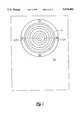
- FIG. 2is a plan view of the Oil Monitor showing the sensor
- FIG. 3is a somewhat diagrammatic perspective view of the Oil Monitor
- FIG. 4is a circuit diagram of the sensor and associated analog circuit
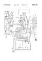
- FIG. 5is a circuit diagram of the microprocessor and associated circuitry that monitors the sensor and produces an output
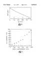
- FIG. 6is a graph of frequency vs time data taken by the invention from uncontaminated lubricating oil
- FIG. 7is a graph of frequency vs time data taken by the invention from lubricating oil used in a pump having significant use and wear;
- FIG. 8is a graph of frequency vs time data taken by the invention from lubricating oil used in a turbine having approximately 0.13% water entrained thereon;
- FIG. 9is a representative graph of the invention Contamination Index vs Water Content
- FIG. 10is a graph of the invention Ferromagnetic Index vs Iron Content
- FIG. 11is a graph of the invention OilLife IndexTM vs. percentage of water entrained in lubrication oil
- FIG. 12illustrates an expanded use embodiment of the invention
- FIG. 13is a sectioned detail of the invention representing a first operational mode
- FIG. 14is a sectioned detail of the invention representing a second operational mode
- FIG. 15is a sectioned detail of the invention representing a third operational mode
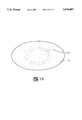
- FIG. 16is detail of a typical magnetically classified concentration of particles on the deposition surface.
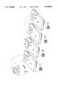
- FIGS. 17 though 20represent a procedural sequence for transferring a test specimen from a deposition surface to a second, examination surface.
- FIG. 21is a sectional detail of the invention representing an alternative embodiment of the magnet.
- FIG. 1a container 10 for holding the sample of lubricating oil that is to be tested.
- the containerhas an open mouth 12 and a removable and resealable lid 14 for sealably attaching over the mouth 12.
- the container 10is placed in a measurement position which preferably entails orienting the container 10 vertically with the mouth 12 situated downward so that the mouth 12 covers a horizontally placed sensor element 16 thereby allowing the oil to flow down into direct wetted contact with the surface of sensor element 16.
- the measurement positionfurther allows gravity to influence the oil held in the container 10 thereby causing any contaminants in the oil to migrate downwardly toward the upper support surface of sensor element 16.
- the sensor element 16is symbolically represented and is shown removed from the mouth 12 for clarity of illustration. It will be understood that the sensor element 16 seals against the mouth 12 to close the container 10 and contain the oil.
- An electromagnet 20is placed vertically beneath the sensor element 16.
- This electromagnet 20comprises an axial rod core 19 and a cylindrical case 21. Electrical windings 17 occupy the annulus between the rod 19 and the case 21.
- a permanent magnet 18is located coaxially beneath and in direct contact with the electromagnet 20 to take advantage of the electromagnet core rod 19 for casting the permanent magnet field along the core rod axis.
- the field of the electromagnet 20acts in conjunction with the permanent magnet 18 field in variable degrees depending on the polarity of the electromagnet 20.
- the electromagnet 20is electrically connected to switch 22 which is in turn electrically connected to an electromagnet voltage supply 23.
- the switch 22 and the electromagnet voltage supply 23allow the electromagnet to be turned on in a north-south orientation, turned on in a south-north orientation, or turned off.
- the switch 22 in the preferred embodimentis electrically connected to a microprocessor circuit 24 which controls the change in the polarity of the electromagnet 20 as well as the rate at which the electromagnet 20 is turned on and off, which is preferably about one (1) cycle per second.
- the electromagnet 20is a model EMR75 manufactured by Miami Magnet Company operating at 12 volts and about 750 milliamps.
- the permanent magnet 18has a diameter of one inch, a thickness of one quarter (1/4) inch and a strength that about matches electromagnet 20.
- the electromagnet 20is de-energized or switched "off" to produce a relative polarity with the upper ends of both the rod core 19 and the cylindrical case 21 having the same polarity as the upper end of the permanent magnet 18.
- the dominant alignment of the flux patternis normal to the surface of the sensor element 16. Consequently, magnetically responsive particles 15 biased against the sensor surface by the magnet field tend to orient the long dimension of the particle parallel with such flux lines at substantially 90° of the sensor surface.
- the net magnetic bias upon the magnetically responsive articles within the container 10confined sample of oil supports or reinforces gravity to draw or drive the particles into or against the surface of sensor element 16.
- FIG. 14represents an electromagnet energy condition wherein the upper end of the rod core 19 is N but the upper end of the cylindrical case 21 is S.
- This configurationpermits a large percentage of the field to shunt directly across from the end of the rod 19 to the end of the case 21 which are opposite poles for magnetic loop completion.
- the remaining field patternissues from the upper corners of the rod core 19 at relatively low angles which align the particles 15 at 25° to 45° of the sensor surface.
- FIG. 15energizes the electromagnet winding 17 to produce a rod core 19 upper end polarity the same as the permanent magnet 18 lower end.
- the resultis a low flux trajectory across the sensor element surface which aligns the particles 15 at an extremely low or 0° angle to the sensor surface.
- the sensor element 16is electrically connected to an oscillator circuit 26 which uses the sensor 16 as a capacitor to generate an output signal at a natural frequency corresponding to the capacitance.
- the oscillator circuit 26is electrically connected to the microprocessor circuit 24 which uses the generated signal frequency to determine the presence and magnitude of corrosive products, contamination, and ferromagnetic particles in the oil.
- the microprocessor 24is electrically connected to the display 28 which outputs the results of the microprocessor's determinations.
- FIG. 2depicts an enlarged, somewhat diagrammatic, top view of the preferred embodiment of the sensor 16 as mounted to the test box 30 which also contains the permanent magnet 18, the electromagnet 20, the switch 22, the electromagnet voltage supply 23, and the oscillator circuit 26 of FIG. 1.
- the preferred sensor element 16is constructed in a open grid-like formation and is formed from two conductors 32a and 32b having extensions forming concentric half circles.
- Preferred fabrication technologyis drawn from printed circuit manufacture whereby a thin film of electrically conductive material such as copper, silver or gold is deposited upon an insulating structural substrate such as fiberglass, alumina ceramic or beryllia ceramic.
- Photo masking procedurespermit a precisely delineated removal of undesired film by chemical etching to leave the conductive film material in the illustrated grid pattern as conductors 32A and 32B.
- the remaining conductive gridmay be protected from corrosion by a coating of gold or of lead and tin.
- the oil which wets the sensor 16 surfaceacts as the insulating dielectric medium between the conductors 32a and 32b.
- the conductors 32a and 32bact as capacitor plates with the capacitance varying with, at least, the area of the conductors 32a and 32b, the distance between the conductors 32a and 32b, and the dielectric constant of the oil.
- the sensorhas a diameter of about one inch; the conductors 32a and 32b have a diameter of about 250 microns and are spaced apart a distance of about 250 microns; and the sensor 16 has a capacitance in air of about 30 picofarads.
- FIG. 3depicts an external, somewhat diagrammatic, view of the preferred embodiment of the apparatus.
- the container 10is shown in the measurement position on the test box 30.
- a shielded serial cable 34electrically connects the components in the test box 30 at connector port 74a to those components in the display box 36 by means of connector port 74b.
- the display box 36encloses the microprocessor 24 of FIG. 1.
- the display 28is preferably an LCD display for displaying the value of contamination, corrosion and ferromagnetic particle levels.
- the display 28is mounted on the display box 36 and is electrically connected to the microprocessor 24 within the box. Further depicted are three LEDs, 38a, 38b and 38c, that are electrically connected to the microprocessor 24 within the display box 36 and energized corresponding to the changing levels of corrosion, contamination or ferromagnetic particles.
- FIG. 4depicts the preferred embodiment of the internal circuitry of the test box 30 shown in FIG. 3.
- the oscillator circuit 26performs the function of generating a frequency pulse based upon the capacitance of the sensor 16.
- the oil in the sensor 16acts as the dielectric medium, thereby altering the capacitance of the sensor.
- the capacitanceincreases as the dielectric constant increases (see Formula 1) causing an overall decrease in the natural frequency produced by the oscillator circuit 26 (see Formula 2).
- kthe dielectric constant of the oil in the sensor 16
- Athe surface area of the sensor 16
- the presence of polar oxides in the oilcauses an increase in the dielectric constant. Additionally, since water has a higher dielectric constant than oil, its presence in the oil will cause an increase in the dielectric constant of the oil as the water settles into the vicinity of the sensor element 16 to displace oil from between the conductors 32A and 32B. If a substantial quantity of water accumulates on the sensor 16, it can cause the sensor 16 to be shorted.
- the presence of ferromagnetic particles 15 in the oilalso causes an increase in the capacitance of the sensor 16 because the accumulation in particles on the sensor increases the sensor's surface area and capacitance in accordance with Formula 1.
- the sensor element 16is connected to a pin 42 of a monostable multivibrator 40 and is connected in parallel with the resistor 44 to pin 46 and pin 48 of the monostable multivibrator 40.
- a constant voltage source 50is connected to pins 52, 54 and 56 of the monostable multivibrator 40 while pins 58, 60 and 62 are grounded. Pins 52, 54 and 56 are also connected to ground through a, preferably, 0.1 microfarad capacitor 57.
- sensor 16is a variable capacitor connected in an R-C circuit to influence the frequency of the signal (pulses) transmitted from pin 64.
- the preferred monostable multivibratoris a general CMOS logic chip Model 4047. The oscillator circuit is trimmed to a natural frequency of about 60,000 Hz with the sensor element 16 wetted by uncontaminated kerosene.
- the pin 64 which carries the oscillator signal pulsesis connected to a pin 68 of a non-inverting buffer chip 66 which isolates the signal and outputs it from pin 70.
- the pin 70is connected to a pin 72a of a connector port 74a. A signal is thereby sent through the connector port 74a along the serial cable 34 of FIG. 3 to an identical connector port 74b of the display box 36 of FIG. 3.
- the connector port 74aalso receives signals from the microprocessor 24 from pins 76a and 78a of the connector port 74a. These signals control the switch 22 for changing the polarity of the electromagnet 20 and for turning the electromagnet 20 on or off.
- the electromagnetwhen turned on in opposition to or reinforcing the permanent magnet 18, will cause the particles 15 on the sensor element surface to shift thereby changing the surface area of the sensor which results in an altered frequency output from the monostable multivibrator 40.
- the electromagnetwill cause a fluctuation in output pulses as its polarity is changed if ferromagnetic particles are present in the oil.
- an electromagnetis employed for shifting the ferromagnetic particles 15 on the surface of sensor 16, but it will be understood by those of ordinary skill in the art that a similar effect could be produced by a pair of mechanically manipulated permanent magnets as illustrated by FIG. 21.
- Permanent magnet 240is a rod magnet secured directly beneath the sensor element 16 with the rod axis perpendicular to the sensor element plane. Coaxially surrounding the rod magnet 240 is a cylinder magnet 242.
- the cylinder magnet 242is axially reciprocated as by a crank mechanism along the length of the rod magnet.
- the pole ends of the two permanent magnetsare respectively opposite thereby causing dramatic change in the flux pattern across the sensor element 16 to effect movement of deposited particles that could be shifted or rotated to change the magnetic field.
- the electromagnet's polarityis cycled from an "off" status to a N-S polarity to a S-N polarity to produce the maximum fluctuation of particles 15 while continuously attracting particles with the permanent magnet 18.
- total reversal of the polarity of the electromagnetis not required.
- the pin 76a of connector port 74ais connected to a pin 80 of the buffer chip 66 which isolates the switching signal and outputs it from pin 82.
- the pin 82is connected in series with a resistor 84 to the base of an NPN transistor 86.
- the pin 78a of connector port 74ais connected to pin 88 of the buffer chip 66 which isolates the signal and outputs it from the pin 90.
- the pin 90is connected in series with a resistor 92 to the base of an NPN transistor 94.
- the emitters of the transistors 86 and 94are tied together and attached to a signal ground wire 95 which acts to reduce noise in the system.
- the collector of transistor 86is connected in series through resistors 96 and 98 to the electromagnet power supply 23, which provides V mag , and further connected through resistor 98 to the base of a PNP transistor 100.
- a diode 102is coupled across the emitter and collector of transistor 100 thus acting as a protection device for transient relief.
- the emitter of transistor 100is further connected to the electromagnet voltage supply 23, and the collector of transistor 106 is further coupled to the electromagnet 20.
- the collector of transistor 94is connected in series to the electromagnet power supply 23 through resistors 104 and 107 and is further connected to the base of a PNP transistor 106 through resistor 107.
- a diode 108is coupled across the emitter and collector of transistor 106 thus acting as a protection device for transient relief.
- the emitter of transistor 106is further connected to the electromagnet voltage supply 23 (preferably a battery), and the collector of transistor 106 is further connected to the electromagnet 20.
- the pin 82 of the buffer chip 66is also coupled with a pin 112 of a Darlington driver chip 110 which operates as a current sink, dependent upon the logic level, and is connected from pin 114 to the electromagnet 20 in conjunction with the collector of transistor 106.
- the pin 90 of buffer chip 66is connected to a pin 116 of the driver chip 110 which is in turn coupled from pin 118 to the electromagnet 20 in conjunction with the collector of the transistor 100. This configuration allows the current flow to the electromagnet 20 to be alternated or shut off completely by the microprocessor 24 thus providing the switch 22.
- the driver chip 110is connected to the signal ground wire 95 through a pin 118 and is connected to the electromagnet voltage supply 23 through a pin 120 which is further coupled through a series capacitor 122 to the signal ground wire.
- the signal ground wire 95is connected to pin 124a of the connector port 74a.
- the connector port 74ahas pins 126a, 128a, and 130a connected to ground and has pin 132a connected through a diode 134 to the electromagnet power supply 23.
- the buffer chip 66has pin 136 connected to the constant voltage source 50 which is in turn coupled to ground through capacitor 138.
- the buffer chipalso has pins 140, 142 and 144 coupled to ground.
- FIG. 5depicts the internal circuitry of the display box 36 of FIG. 3.
- the connector port 74bconnects the test box 30 to the shielded serial cable 34.
- the pin 72bcarries the oscillator pulse and is connected to the microprocessor 24 at pin 146.
- the preferred microprocessoris an HCMoss microcontroller unit model MC68HC705C8 with erasable programmable read only memory.
- the microprocessor 24counts the number of pulses produced by the multivibrator 40 per unit of time to determine the amount of contamination, corrosive products and ferromagnetic particles in the test oil.
- a fresh, petroleum-based lubricating oilis primarily composed of hydrocarbon molecules with no net electrical charge and which are weakly polar or have a non-polar charge distribution.
- Fresh mineral oilscan be characterized as having a very high electrical resistance and a relatively low dielectric constant (permittivity). These electrical properties change as the oil degrades and becomes contaminated. Specifically, increases in insoluble content, the presence of moisture and acids, or the presence of conductive metallic debris will increase the dielectric constant of an oil, or reduce its resistance, or both.
- a combined measure of permittivity and resistivitycan be made by measuring the AC impedance or effective capacitance (rate of charge over applied potential) across two plates separated by a quantity of oil.
- An approximate model for the systemis an ideal capacitor influenced primarily by permittivity and a parallel resistance primarily influenced by ionic conduction.
- Charge mobility not involving conductive particles in a dielectric fluidinvolves mechanical motion of charged or dipole particles in the fluid. Therefore, system impedance is tied to the parameters which describe the hydrodynamics of particles moving in a fluid. These parameters include the temperature-dependent oil viscosity, the applied (electrical) forces, particle size, and particle shape.
- the strength of the present inventionis based on measuring the time-rate-of-change of effective capacitance in the presence of time-varying magnetic and electric fields over a standard test period, 500 seconds, for example. These applied fields act along with gravity to draw ferromagnetic particles, polar insolubles, and conductive metal particles down onto the sensor 16. Consequently, the time-rate-of-change values are specifically related to the amount and species of contaminates which are extracted from the oil rather than to the general, bulk oil properties.
- the inventionuniquely identifies ferromagnetic debris by comparing the time-rate-of-change in a magnet-off state to the time-rate-of-change in the polarity opposite magnet-on states.
- the instrumentalso reads the absolute effective capacitance at the beginning of the test. This value can be used to compare the test oil to a sample of the fresh bulk oil when the results of the fresh oil calibration test have been stored. The comparison provides a non-specific indication of changes in the bulk oil chemistry. In the absence of a calibration sample, this value should still be tended over time to detect sudden changes in bulk oil chemistry which typically accompany additive depletion or gross contamination.
- FIG. 6illustrates how the invention "sees" a fresh oil.
- the broad curve across the top of the plotrepresents sequential frequency readings of an oscillating circuit which decreases with the increases in effective system capacitance.
- the plotis smooth with very little downward slope indicating that there was little change in the effective capacitance during the test. We know, therefore, that the contaminate population is small and benign. There are no diverging curves for the magnet on states.
- FIG. 7illustrates how the instrument "sees" the same pump oil after it has been in service in a pump experiencing significant wear. Note the much steeper downward slope and the increasing separation of the magnet on states (two lower curves) from the upper magnet off state curve. This separation is the indication of ferrous debris. Also note that in this case the magnet on curves have a jagged and spiked profile at about 120 seconds into the test when relatively large magnetic particle(s) were forced onto the sensor, while the magnet off curve is relatively smooth.
- FIG. 8illustrates how a turbine oil with roughly 1300 ppm (0.13%) water appears to the instrument. There is a steep and nearly linear downward slope indicating that the contaminate is being primarily drawn onto the grid by gravity rather than by the magnetic fields with their spatial gradient. This is confirmed by the fact that there is also no divergence of the magnet on curves from the magnet off curves. Also note the perturbation in the curve at about 260 seconds caused by a droplet of "free" water contacting the grid as opposed to finely dispersed moisture.
- the microprocessorthen begins receiving and counting the pulses output from the monostable multivibrator 40. Pulse counts are made when the electromagnet is turned on in north-south polarity, turned on in south-north polarity, and turned off. In the preferred embodiment, these three count readings constitute one cycle.
- the mean calibration value, Meis determined over a number of cycles, preferably, twenty cycles, and, preferably, the first ten of which are counted and ignored. During each cycle between ten and twenty cycles, the pulse count is stored while the electromagnet is off, and the mean value of the stored pulse counts is stored as M c .
- the number of cycles used to determine M cis a matter of design choice, but it is preferred to ignore the first few cycles and then determine an average based on a number measurements taken over a number of cycles.
- the pulse count when the electromagnet is offis stored as the magnet-off calibration value OFF c . Furthermore, the difference between the electromagnet when off and when on in north-south polarity is stored N c . and the difference between the electromagnet when off and when on in south-north polarity is stored S c . After these calibration values are stored, the microprocessor 24 reconfigures and resets its internal flags for test mode. Since the values obtained in the calibration mode are used as the "normal" values for the oil, a poor calibration oil will cause the test sequence to produce improper results.
- the test modeis run by filling the container 10 with the test oil and placing the container in measurement position.
- the microprocessor 24then begins running test cycles. After twenty cycles (preferably) have been run in the test mode, the microprocessor 24 stores the mean pulse count obtained between the tenth and the twentieth cycles (preferably) when the electromagnet is turned off as the mean test value M T . This mean value M T is subtracted from the similarly obtained calibration value M c and the difference is output to the LCD display 28 as the Corrosion Index R.
- This indexis a measure of changes in bulk oil chemistry. An increase in this index indicates that the oil is increasingly able to support electrical conduction owing to the presence of polar molecules, moisture, or suspended, charge-bearing particulate. These conditions typically lead to increased wear and corrosion. The most common causes of an increase in this index include thermally accelerated oxidation and nitration, the formation of acids from combustion blow-by in engines, and increased moisture content.
- the microprocessor 24subtracts the pulse count taken when the electromagnet is turned off (the magnet-off test value OFF T ) from the mean test value M T , and the difference between the magnet-off calibration value OFF c and the mean calibration value M c is further subtracted.
- the resultant valueis output to the LCD display 28 as the Contamination Index C.
- This indexis a measure of the level of oil-insoluble contaminants in the oil as opposed to changes in the bulk oil chemistry.
- Some common contaminantsinclude water, glycol coolants, metallic wear debris, large insoluble by-products of combustion, and abrasive solids such as road dust.
- the contamination index valueis updated similarly each cycle using the magnet off test value OFF T for each cycle. This method of determining the contamination allows any pulse offsets due to corrosion to be disregarded. Furthermore, the testing for contamination during each cycle allows for the time that it takes for gravity to draw the contaminants into the vicinity of the sensor 16.
- FIG. 9is a plot of the Contamination Index for a series of test samples prepared by introducing known amounts of water into a fresh turbine oil. Again, note the linear relationship between the test data and the known concentrations.
- the instrumentis capable of detecting water at concentrations as low as 100 ppm by weight in light oils. It should be noted that the contamination index is sensitive to the conductivity of a contaminant as well as its concentration. In practice this means that it will assign a higher value to highly corrosive salt water than it will to less damaging clean water. In either case the instrument will detect "free" water as opposed to finely dispersed water.
- the difference between the pulse count when the electromagnet 20 is off and the pulse count when the electromagnet 20 is onis determined. This determination is made for the difference when the electromagnet is in both polarities and stored as N T and S T . Similar values obtained from the calibration mode are then subtracted from the test mode values with the resultant values outputted to the LCD display 28 as the Ferromagnetic debris Index F x .
- This indexis sensitive to conductive, ferromagnetic particles. It increases with particle size, surface conductivity, and debris concentration. The index is primarily sensitive to recent, severe wear of oil-wetted steel and iron parts. Similar values may be obtained in succeeding cycles and added to the previous value so that a running total is obtained and displayed.
- FIG. 10is a plot of the Ferromagnetic Index from a series of tests conducted with a fresh turbine oil contaminated with varying known amounts of 4 to 6 micron iron particles. Note the linear relationship between known content and the index. The instrument will detect iron debris concentrations as low 1 ⁇ g/ml.
- this indexis sensitive to particle size as well as particle concentrations. For a given concentration this index Will increase with particle size. This size sensitivity aids in detecting the large particles produced by abnormal (as opposed to normal) wear.
- OilLife IndexTMis the product of an algorithm which reflects the combined effect of oil degradation and contamination, i.e. when the oil is no longer suitable for continued use due to oxidation or acidity or the presence of corrosive fluids such as glycol or water or the presence of conductive particles.
- This OilLife IndexTMrelies upon a 500 cycle data base wherein the median of the last five (496-500 cycle) magnet-off oil calibration values CAL are reduced by the median of the last five (496-500 cycles) magnet-off oil test values TES and the sensor noise value NOS. This summation is divided by a suitable constant, C. ##EQU2##
- FIG. 11graphs the OilLife IndexTM value determination respective to percentage of moisture content contaminating two synthetic compressor lubricants. Note will be taken of the Index data linearity on both lubricant examples.
- the microprocessor 24uses pins 148, 150, 152, 154, 156, 158, 160, 162, 164 and 166 to output the index values to the display 28.
- LEDsare used as a further indicator of the condition of the oil.
- the microprocessor 24sends a signal to a green LED 38a, which is tied to the constant voltage source 50 through a resistor 170. The signal is sent from pin 172 thereby energizing the green LED 38a.
- the green LED 38ais de-energized and the yellow LED 38b is energized by a signal from pin 176 of the microprocessor 24 to indicate the need for caution because of a borderline oil sample.
- the yellow LED 38bis connected to the constant voltage source 50 through a resistor 178.
- the yellow LED 38bis de-energized and the microprocessor sends a signal through a pin 180 to energize a red LED 38c, which is connected to the constant voltage source 50 through a resistor 184, to thereby indicate that the oil sample is "bad.”
- the red LED 38cwill be pulsed and the word "CRITICAL" will be sent to the display 28.
- the microprocessor 24receives the pulse counts for 100 cycles and then stops if the Contamination index and the Ferromagnetic debris index values remain very small. However, if the Contamination or Ferromagnetic debris indicates an appreciable amount of deterioration in the oil, the microprocessor continues receiving for 500 cycles to determine the full amount of the contaminants. The word "FINISHED" will be sent to the display 28 when the microprocessor 24 completes its readings.
- the microprocessorchecks for a high reading on pin 186 to determine if the test should be aborted. Aborting occurs by pressing the test button while in test mode.
- the pin 186is connected to the constant voltage source 50 through a resistor 188 and to the test button 37 which connects to ground when pressed, thereby allowing the line to be driven high.
- the microprocessorcontrols the polarity and the power to the electromagnet 20 by output signals from pins 202 and 204 which are connected to pins 76b and 78b of the connector port 74b.
- the signalsare transferred along the shielded serial cable 34 to the connector port 74a of the test box 30.
- a low signal generated on both pins 202 and 204will force the electromagnet 20 into its "off” mode.
- a high signal generated upon pin 202, while a low signal is generated on 204will force the electromagnet into the "on” mode in north-south polarity.
- a high signal generated upon pin 204, while a low signal is generated on pin 202will force the electromagnet into the "on” mode in south-north polarity.
- a reset circuit 206 including resistors 208 and 210 connected to capacitors 212 and 214is attached to the constant voltage source 50 and acts to pull up the input voltage to five volts after the supply contact is made.
- the reset circuit 206is attached to pins 216, 218 and 220 of the microprocessor 24, thereby assuring that the internal reset of the microprocessor is working properly.
- a beeper alarm 222is used for signaling the presence of dangerous levels of deterioration and contamination in the test oil.
- the beeper 222is attached through a capacitor 224 to a pin 226 of the microprocessor 24.
- the connector port 74bhas a pin 124b connected to a probe ground wire 228 which is connected to a power clip 230 for hook up to an external power source.
- the switch 39engages the external power source when depressed thereby powering the electromagnet voltage supply 23.
- the switch 39is further connected to a voltage regulator 232 which regulates the voltage to five volts for supplying the constant voltage source 50 which powers the digital requirements of the system.
- the electromagnet voltage supply 23is connected to the probe ground wire 228 through resistor 234, and the constant voltage source 50 is similarly connected to the ground wire 228 through resistor 236.
- the connector port 74bhas pins 126b and 130b connected to ground.
- the connector port 74bfurther has pin 132b connected to the electromagnet voltage supply 23.
- FIG. 12illustrates a suitable viewing apparatus for this purpose which comprises a microscope 11 having an optics tube 13 that is axially slidable within an open bottom support base 15. Focal adjustment of the optic tube is made by rotation of the adjustment knob 17.
- a wall opening 19 in-the support base 15permits the microscope viewing area 21 at the bottom of base 15 to be illuminated by a lamp such as battery powered penlight 25.
- the support base bottomis sized to cover or fit in or over the sensor 16 so as to place the contaminant deposition surface of the sensor 16 in the microscope viewing area 21.
- the unitReversing the procedure for connectively sealing the sample container 10 to the sensor 16, the unit is gently inverted from the test position to drain the oil sample away from the container mouth 12 interface with the sensor 16. This inverting process is carried out with such care as to avoid disruption of the contaminant deposition pattern on the sensor 16. Oil surface tension and presence of the permanent magnet 18 field is normally sufficient to secure the contaminant pattern during a careful inversion.
- the seal between the container and the sensormay be separated and the container 10 confined sample fluids removed from contact with the sensor element 16 leaving the accumulated deposits of contaminant particles exposed openly on the sensor element surface.
- the contaminant particle deposition patterns and organizationmay be visually scrutinized and analyzed under different lighting and stimulation conditions.
- the depositsmay be viewed under the illumination of spectrally restricted light such as violet, red or yellow.
- an optic tube 13 eyepiece filtermay be positioned to accomplish similar results.
- a cameramay be connected to the optic tube to photograph the deposits on video tape or spectrally specific film.
- the electromagnet 20may be actuated to stimulate movement of the magnetically responsive particles thereby revealing their unique magnetic classification patterns which conform to the permanent magnet flux lines. In the presently preferred embodiment of the invention shown by FIG. 16 this magnetic classification is revealed in a circle of clustered magnetic material 15 deposited on the sensor 16 surface opposite of the electromagnet core 19 perimeter.
- These magnetically responsive and geometrically distributed particles 15will physically move in alternating unison to the magnetic field pole reversals. Randomly distributed non-magnetic material has no response to the presence or absence of the alternating magnetic field. Due to random shapes with unbalanced aspect ratios and a continuing magnetic field vector urging the magnetically responsive particles onto and against the deposition surface of the sensor element 16, these particles move by pivoting about a fixed point.
- This visual informationmay reveal the extent of damage occurring to a machine as well as the cause. Most wear particles in a lubricant result from three root causes: adhesive wear, abrasive wear or metal fatigue.
- Adhesive wearis that which results from sliding, scuffing, or rubbing contact between surfaces. Sliding type adhesive wear is common and quite normal wear which takes place for most applications. Scuffing and rubbing are not normal.
- Normal adhesive weargenerates very small (0.1 to 5 microns) wear particles as high spots are sheared down.
- Abnormal adhesionresult of scuffing or rubbing
- sliding wear particlesare plateletts having three dimensional aspect ratios of 50:50:1.
- Abrasive wearis the cutting action normally caused as hard particles gouge out long (10 to several hundred microns) and sometimes curled strips of metal. Sand or metal wear particles are frequently the cause of abrasive wear. Abrasive wear particles eventually are broken into smaller pieces as they are milled by the gears and other machinery components. Accordingly, abrasion products exhibit aspect ratios of 10:1 to 100:1.
- Fatiguealso called “high cycle fatigue” occurs when the metal surfaces fail due to repeated cyclic loading. This is commonly seen on gear teeth and rolling element bearings.
- Fatigue particlestend to be relatively large (10 to 20 microns) having blocky or spherical shape with aspect ratios of 1:1 to 10:1.
- the presence of spherical particlesusually is a very strong indication of fatigue failure. These particles are generated when sub-surface cracks allow a chunk of material to break free which then rolls around. When the surface connected cracks join to release a blocky surface particle, the sub-surface spherical particles are released.
- oil contamination material in the oil sample volume deposited on the sensor surface 16 by gravity and magnetic attractionare transferred from the original accumulation surface to a separate analyzing surface.
- a separate analyzing surfacemay, for example, provide greater electromagnetic field strength or complex illumination or light filter capacities for amplified analysis.
- the deposits 15are bodily transferred in their originally deposited organization by means of a blotter 35 or slide supported adhesive gel.
- the capacitance measuring function of the inventionthe blotter 35 holding the deposits 15 is positioned upon the magnetic field exposed surface of a second test box 33.
- the deposition surface of the first test box 30 sensor 16may be covered with a transfer sheet such as a filter paper 35 or transparent film as a direct deposition surface to lift the contaminant specimen bodily intact from the first test box 30 sensor 16 with a minimum of magnetic classification disturbance and placed upon the magnetic field surface of second test box 33.
- a transfer sheetsuch as a filter paper 35 or transparent film as a direct deposition surface to lift the contaminant specimen bodily intact from the first test box 30 sensor 16 with a minimum of magnetic classification disturbance and placed upon the magnetic field surface of second test box 33.
- the maintenance and operations personnelmay choose and pursue the correct follow up actions. For instance, after detecting abrasive wear particles, the oil and filter should be changed. Seals and air filters should be inspected to determine how sand or dirt might be getting into the tube system. Similar logical actions can be derived for the other forms of wear.
Landscapes
- Chemical & Material Sciences (AREA)
- Life Sciences & Earth Sciences (AREA)
- Health & Medical Sciences (AREA)
- Engineering & Computer Science (AREA)
- General Physics & Mathematics (AREA)
- Analytical Chemistry (AREA)
- Biochemistry (AREA)
- General Health & Medical Sciences (AREA)
- Physics & Mathematics (AREA)
- Immunology (AREA)
- Pathology (AREA)
- Oil, Petroleum & Natural Gas (AREA)
- Chemical Kinetics & Catalysis (AREA)
- General Chemical & Material Sciences (AREA)
- Food Science & Technology (AREA)
- Medicinal Chemistry (AREA)
- Dispersion Chemistry (AREA)
- Investigating Or Analyzing Materials By The Use Of Magnetic Means (AREA)
- Investigating Or Analyzing Materials By The Use Of Electric Means (AREA)
Abstract
Description
Formula 1:
C=k*E*(A/d)
Formula 3:
R=M.sub.c -M.sub.T
Formula 4:
C=(M.sub.T -Off.sub.T)-(M.sub.c -OFF.sub.c)
Formula 5:
F.sub.x =(N.sub.c -N.sub.t)+(S.sub.c -S.sub.t)
Formula 6:
F.sub.TOT =F.sub.x +F.sub.x+1
Claims (12)
Priority Applications (1)
| Application Number | Priority Date | Filing Date | Title |
|---|---|---|---|
| US08/578,878US5674401A (en) | 1991-12-11 | 1995-12-22 | Oil monitor with magnetic field |
Applications Claiming Priority (4)
| Application Number | Priority Date | Filing Date | Title |
|---|---|---|---|
| US07/807,041US5262732A (en) | 1991-12-11 | 1991-12-11 | Oil monitor with magnetic field |
| US13496893A | 1993-10-13 | 1993-10-13 | |
| US08/470,279US5614830A (en) | 1991-12-11 | 1995-06-06 | Oil monitor with magnetic field |
| US08/578,878US5674401A (en) | 1991-12-11 | 1995-12-22 | Oil monitor with magnetic field |
Related Parent Applications (1)
| Application Number | Title | Priority Date | Filing Date |
|---|---|---|---|
| US08/470,279Continuation-In-PartUS5614830A (en) | 1991-12-11 | 1995-06-06 | Oil monitor with magnetic field |
Publications (1)
| Publication Number | Publication Date |
|---|---|
| US5674401Atrue US5674401A (en) | 1997-10-07 |
Family
ID=27384648
Family Applications (1)
| Application Number | Title | Priority Date | Filing Date |
|---|---|---|---|
| US08/578,878Expired - LifetimeUS5674401A (en) | 1991-12-11 | 1995-12-22 | Oil monitor with magnetic field |
Country Status (1)
| Country | Link |
|---|---|
| US (1) | US5674401A (en) |
Cited By (68)
| Publication number | Priority date | Publication date | Assignee | Title |
|---|---|---|---|---|
| WO2001061339A1 (en)* | 2000-02-16 | 2001-08-23 | Kaiku Limited | Method and apparatus for the debris particulate characterization in lubricants |
| WO2001075183A3 (en)* | 2000-03-31 | 2002-05-23 | Worcester Polytech Inst | System for detecting inclusions in molten metals |
| US6449580B1 (en) | 1998-05-11 | 2002-09-10 | Entek Ird International Corporation | Evaluating properties of oil using dielectric spectroscopy |
| US20020140564A1 (en)* | 2001-03-29 | 2002-10-03 | Steven Danyluk | Contact potential difference sensor to monitor oil properties |
| US6463796B1 (en)* | 2000-10-12 | 2002-10-15 | The Lubrizol Corporation | Continuous on-board diagnostic lubricant monitoring system and method |
| US6582661B1 (en) | 2000-06-30 | 2003-06-24 | Csi Technology, Inc. | Integrated lubricant analyzer |
| US6590200B1 (en) | 1999-04-02 | 2003-07-08 | Worcester Polytechnic Institute | Systems for detecting measuring inclusions |
| US20040019461A1 (en)* | 2002-04-22 | 2004-01-29 | Kai Bouse | Machine fault information detection and reporting |
| US6691557B1 (en) | 2000-03-17 | 2004-02-17 | Norman Rice | Analysis method for liquid-filled electric equipment |
| US6693443B2 (en)* | 1999-04-02 | 2004-02-17 | Worcester Polytechnic Institute | Systems for detecting and measuring inclusions |
| EP1521081A1 (en)* | 2003-09-30 | 2005-04-06 | Rockwell Automation Technologies, Inc. | Lubricity measurement using mems sensor |
| US6928861B1 (en) | 2000-03-17 | 2005-08-16 | Norman Rice | Method for a reliability assessment, failure prediction and operating condition determination of electric equipment |
| US20060105467A1 (en)* | 2004-11-12 | 2006-05-18 | Niksa Andrew J | MEMS-based sensor for lubricant analysis |
| EP1748295A1 (en)* | 2005-07-28 | 2007-01-31 | Nederlandse Organisatie voor toegepast-natuurwetenschappelijk Onderzoek TNO | System for manipulating magnetic particles |
| WO2007036955A1 (en)* | 2005-09-30 | 2007-04-05 | Seth, Chandan, Kumar | Split cycle rotary internal combustion engine |
| CN100365413C (en)* | 2006-02-09 | 2008-01-30 | 西安交通大学 | Short deposition distance image type online ferrography device and method |
| CN100365410C (en)* | 2005-04-04 | 2008-01-30 | 西安交通大学 | On-line digital image type electromagnetic permanent magnet hybrid excitation spectrum sensor |
| US20080174323A1 (en)* | 2007-01-19 | 2008-07-24 | Honeywell International, Inc. | Corrosion sensor to monitor and control the acidity of the lube oil and hydraulic oil |
| US7493799B1 (en)* | 1998-04-02 | 2009-02-24 | Rockwell Automation Technologies, Inc. | System and method for dynamic lubrication adjustment for a lubrication analysis system |
| FR2922472A1 (en)* | 2007-10-22 | 2009-04-24 | Snecma Sa | Short-blasting ball detecting, localizing and counting method for hollow mechanical piece, involves deducing presence of short-blasting ball at measuring point and number of short-blasting balls at measurement point |
| US7581434B1 (en) | 2003-09-25 | 2009-09-01 | Rockwell Automation Technologies, Inc. | Intelligent fluid sensor for machinery diagnostics, prognostics, and control |
| US7862875B2 (en) | 2004-10-04 | 2011-01-04 | Trico Corporation | Flinger disc |
| US8096164B2 (en) | 2008-01-17 | 2012-01-17 | Trico Corporation | Apparatus and methods for management of fluid condition |
| US8147683B2 (en) | 2010-01-22 | 2012-04-03 | Trico Corporation | Portable lubricant filtration system and method |
| US8147684B2 (en) | 2009-03-27 | 2012-04-03 | Trico Corporation | Apparatus and methods for lubricant filtration and drum pump filtration system |
| EP2455774A1 (en)* | 2010-11-19 | 2012-05-23 | ARGO-HYTOS GmbH | Sensor device and method for its operation |
| US8220671B2 (en) | 2008-03-12 | 2012-07-17 | Trico Corporation | Lubricant dispenser with nozzle |
| EP2574905A1 (en)* | 2011-09-29 | 2013-04-03 | Eurocopter Deutschland GmbH | Device and method for monitoring of particles in a lubricating circuit or a hydraulic system |
| USD687922S1 (en) | 2012-04-25 | 2013-08-13 | Trico Corporation | Lubricant dispenser |
| USD687923S1 (en) | 2008-06-03 | 2013-08-13 | Trico Corporation | Lubricant dispensing nozzle |
| USD687921S1 (en) | 2012-04-25 | 2013-08-13 | Trico Corporation | Lubricant dispenser |
| USD696956S1 (en) | 2012-04-25 | 2014-01-07 | Trico Corporation | Lubricant dispenser |
| US20150075268A1 (en)* | 2013-09-13 | 2015-03-19 | Baohua Qi | Fluid Quality Sensing Means with Reference Sensor |
| CN105842305A (en)* | 2016-05-12 | 2016-08-10 | 李伟波 | Method for monitoring wear particles with hydraulic filtering, centrifugal separation and adjacent capacitors |
| CN105865985A (en)* | 2016-05-12 | 2016-08-17 | 绍兴文理学院 | Double-excitation solenoid type particle online detection system with variable-structure filtering function |
| CN105865987A (en)* | 2016-05-12 | 2016-08-17 | 绍兴文理学院 | Method for monitoring oil by means of full-frequency-band variable-structure filtering, adsorbing and molding |
| CN105928844A (en)* | 2016-05-12 | 2016-09-07 | 绍兴文理学院 | Double-coil oil liquid monitoring equipment adopting wave suppression, separation and shaping |
| CN105954156A (en)* | 2016-05-12 | 2016-09-21 | 绍兴文理学院 | Double-excitation-solenoid particle sensitive device adopting variable-structure working condition adaptive filtering |
| CN105954167A (en)* | 2016-05-12 | 2016-09-21 | 绍兴文理学院 | Dual exciting solenoid type particle sensitive device adopting working condition adaptive filtering |
| CN105973776A (en)* | 2016-05-12 | 2016-09-28 | 绍兴文理学院 | Double-exciting solenoid type particle sensing method adopting working condition adaptive filtering |
| CN105973763A (en)* | 2016-05-12 | 2016-09-28 | 绍兴文理学院 | Liquid oil monitoring device adopting full-frequency-band-working-condition adaptive filtering, separating and molding |
| CN105973779A (en)* | 2016-05-12 | 2016-09-28 | 绍兴文理学院 | Method for monitoring wear particles on line by virtue of centrifugation, electric hammer adsorption and adjacent capacitance |
| CN105973777A (en)* | 2016-05-12 | 2016-09-28 | 李伟波 | Method for monitoring wear particles on line by virtue of filtration, electromagnetic centrifugation and adjacent capacitance |
| CN106018501A (en)* | 2016-05-12 | 2016-10-12 | 李伟波 | Wear particle online monitoring method using filtering, centrifugation and adjacent capacitance |
| CN106018220A (en)* | 2016-05-12 | 2016-10-12 | 李伟波 | Abrasion particle on-line monitoring method with hydraulic pressure filtering, centrifugation and adjacent capacitors |
| CN106018213A (en)* | 2016-05-12 | 2016-10-12 | 李伟波 | Wear particle monitoring method using filtering, electromagnetic centrifugal separation and adjacent capacitance |
| CN106018215A (en)* | 2016-05-12 | 2016-10-12 | 绍兴文理学院 | Double-exciting solenoid type abrasion particle online detecting method with filter |
| CN106018212A (en)* | 2016-05-12 | 2016-10-12 | 李伟波 | Wear particle online monitoring method using filtering, centrifugation and adjacent capacitance |
| CN106018190A (en)* | 2016-05-12 | 2016-10-12 | 绍兴文理学院 | Oil monitoring method using full-band working condition adaptive filtering, separation and shaping |
| CN106018218A (en)* | 2016-05-12 | 2016-10-12 | 李伟波 | Wear particle monitoring method achieved through hydraulic filtration, electromagnetic centrifugation and adjacent capacitance |
| CN106018499A (en)* | 2016-05-12 | 2016-10-12 | 李伟波 | Wear particle online monitoring method using hydraulic filtering, centrifugation and adjacent capacitance |
| CN106018219A (en)* | 2016-05-12 | 2016-10-12 | 李伟波 | Wear particle online monitoring method using filtering, electromagnetic centrifugation and adjacent capacitance |
| CN106018192A (en)* | 2016-05-12 | 2016-10-12 | 绍兴文理学院 | Double-coil oil monitoring method with wave suppression, separation and molding |
| US20170248572A1 (en)* | 2014-09-26 | 2017-08-31 | Sikorsky Aircraft Corporation | Lubricant condition assessment system |
| CN108106972A (en)* | 2017-12-08 | 2018-06-01 | 北京理工大学 | A kind of metallic particles on-line detecting system of particle separate type |
| CN109542006A (en)* | 2018-11-27 | 2019-03-29 | 中国航发沈阳黎明航空发动机有限责任公司 | A kind of control method avoiding thermometal bits signalling means false-alarm |
| WO2019115764A1 (en)* | 2017-12-14 | 2019-06-20 | Universität Bielefeld | Detection device and method for the detection of magnetic particles in lubricants |
| US10451603B2 (en)* | 2014-11-21 | 2019-10-22 | Vestas Wind Systems A/S | Contaminant sensor for detecting magnetizable contaminants in lubricant flow |
| CN110715886A (en)* | 2019-10-29 | 2020-01-21 | 南京航空航天大学 | On-line monitoring method of lubricating oil wear debris based on optical low coherence imaging |
| CN112362540A (en)* | 2020-10-26 | 2021-02-12 | 重庆邮电大学 | Oil abrasive particle motion trajectory image monitoring system and detection method |
| US10968795B2 (en) | 2019-04-09 | 2021-04-06 | Ford Global Technologies, Llc | Methods and systems for detection of particles in lubricant |
| CN113252516A (en)* | 2021-06-02 | 2021-08-13 | 爱德森(厦门)电子有限公司 | Externally-penetrated oil liquid electromagnetic detection sensor and manufacturing method thereof |
| US20210262897A1 (en)* | 2020-02-24 | 2021-08-26 | Pratt & Whitney Canada Corp. | Magnetic chip detector and method of use |
| US11549933B2 (en)* | 2020-02-24 | 2023-01-10 | Pratt & Whitney Canada Corp. | Magnetic chip detector and method of use |
| US20230228731A1 (en)* | 2022-01-17 | 2023-07-20 | Pratt & Whitney Canada Corp. | Electromagnetic chip detector |
| US20230296562A1 (en)* | 2022-03-18 | 2023-09-21 | Dana Italia S.R.L. | Metal debris sensor for oil with temperature compensation |
| CN118624710A (en)* | 2024-06-19 | 2024-09-10 | 鄄城现代实验仪器有限公司 | A high-precision rapid tester for water content in crude oil |
| EP4585922A1 (en)* | 2024-01-11 | 2025-07-16 | Honeywell International Inc. | System for detecting debris in a fluid |
Citations (25)
| Publication number | Priority date | Publication date | Assignee | Title |
|---|---|---|---|---|
| US1940772A (en)* | 1932-03-30 | 1933-12-26 | Light Sensitive Apparatus Corp | Oil tester |
| DE591851C (en)* | 1932-05-22 | 1934-01-27 | Emil Von Leesen | Apparatus for the optical, in particular microscopic, determination of iron particles in lubricating oil |
| US2599583A (en)* | 1946-11-15 | 1952-06-10 | Petrolite Corp | Method and apparatus for testing suspensions |
| US2889736A (en)* | 1954-08-17 | 1959-06-09 | Edward M Borg | Oil testing apparatus |
| US3049964A (en)* | 1959-08-10 | 1962-08-21 | Phillips Petroleum Co | Optical oil change indicator |
| US3371574A (en)* | 1963-07-31 | 1968-03-05 | Robert J. Dwyer | Oil detection device utilizing raman radiation |
| US3790279A (en)* | 1971-09-28 | 1974-02-05 | Environment One Corp | Oil contamination monitor with digital signal processing |
| US3892485A (en)* | 1974-05-06 | 1975-07-01 | Gen Electric | Monitoring apparatus for measuring particles suspended in liquid and for measuring the opacity of the liquid |
| US4003661A (en)* | 1974-07-26 | 1977-01-18 | Kabushiki Kaisha Komatsu Seisakusho | Apparatus for detecting contamination of liquid |
| US4029554A (en)* | 1974-05-20 | 1977-06-14 | Naeco Associates, Inc. | Oil test method |
| US4047814A (en)* | 1974-02-27 | 1977-09-13 | Trans-Sonics, Incorporated | Method and apparatus for segregating particulate matter |
| US4302754A (en)* | 1979-02-12 | 1981-11-24 | Technical Development Co. | Wear particle disintegrator monitor |
| US4492461A (en)* | 1981-03-19 | 1985-01-08 | Jones David G | Wear analysis equipment |
| GB2160655A (en)* | 1984-04-09 | 1985-12-24 | David Brian Jones | Method and apparatus for assessing particle deposits |
| GB2165650A (en)* | 1984-04-09 | 1986-04-16 | Dennis Amerena Parker | Method and apparatus for the quantative and qualitative measurement of small metal particles |
| US4646070A (en)* | 1981-11-17 | 1987-02-24 | Nissan Motor Company, Limited | Oil deterioration detector method and apparatus |
| US4677847A (en)* | 1985-09-30 | 1987-07-07 | Aisin Seiki Kabushiki Kaisha | Automotive engine oil monitoring system |
| US4692698A (en)* | 1985-08-12 | 1987-09-08 | Tribometrics, Inc. | Method and device including a bed of ferromagnetic fibers and magnetic flux sensor for measuring the amount of magnetic particles on a liquid |
| US4701713A (en)* | 1984-12-20 | 1987-10-20 | Combustion Engineering, Inc. | Oil and fuel contamination monitoring system |
| US4741204A (en)* | 1987-04-16 | 1988-05-03 | Thermo King Corporation | Measurement of the depletion of basic additives in lubricating oil |
| US4791374A (en)* | 1986-12-12 | 1988-12-13 | The Lubrizol Corporation | Acid sensor |
| US4796204A (en)* | 1984-09-07 | 1989-01-03 | Nissan Motor Co., Ltd. | Oil degradation warning system |
| US4831362A (en)* | 1986-05-16 | 1989-05-16 | Aeroquip Corporation | Failure detection system for a metallic debris detection system |
| US4857829A (en)* | 1988-04-04 | 1989-08-15 | Aichi Steel Works Ltd. | Water-soluble oil property detection device |
| US5064530A (en)* | 1990-06-04 | 1991-11-12 | Caterpillar Inc. | Fluid contamination detecting apparatus |
- 1995
- 1995-12-22USUS08/578,878patent/US5674401A/ennot_activeExpired - Lifetime
Patent Citations (25)
| Publication number | Priority date | Publication date | Assignee | Title |
|---|---|---|---|---|
| US1940772A (en)* | 1932-03-30 | 1933-12-26 | Light Sensitive Apparatus Corp | Oil tester |
| DE591851C (en)* | 1932-05-22 | 1934-01-27 | Emil Von Leesen | Apparatus for the optical, in particular microscopic, determination of iron particles in lubricating oil |
| US2599583A (en)* | 1946-11-15 | 1952-06-10 | Petrolite Corp | Method and apparatus for testing suspensions |
| US2889736A (en)* | 1954-08-17 | 1959-06-09 | Edward M Borg | Oil testing apparatus |
| US3049964A (en)* | 1959-08-10 | 1962-08-21 | Phillips Petroleum Co | Optical oil change indicator |
| US3371574A (en)* | 1963-07-31 | 1968-03-05 | Robert J. Dwyer | Oil detection device utilizing raman radiation |
| US3790279A (en)* | 1971-09-28 | 1974-02-05 | Environment One Corp | Oil contamination monitor with digital signal processing |
| US4047814A (en)* | 1974-02-27 | 1977-09-13 | Trans-Sonics, Incorporated | Method and apparatus for segregating particulate matter |
| US3892485A (en)* | 1974-05-06 | 1975-07-01 | Gen Electric | Monitoring apparatus for measuring particles suspended in liquid and for measuring the opacity of the liquid |
| US4029554A (en)* | 1974-05-20 | 1977-06-14 | Naeco Associates, Inc. | Oil test method |
| US4003661A (en)* | 1974-07-26 | 1977-01-18 | Kabushiki Kaisha Komatsu Seisakusho | Apparatus for detecting contamination of liquid |
| US4302754A (en)* | 1979-02-12 | 1981-11-24 | Technical Development Co. | Wear particle disintegrator monitor |
| US4492461A (en)* | 1981-03-19 | 1985-01-08 | Jones David G | Wear analysis equipment |
| US4646070A (en)* | 1981-11-17 | 1987-02-24 | Nissan Motor Company, Limited | Oil deterioration detector method and apparatus |
| GB2160655A (en)* | 1984-04-09 | 1985-12-24 | David Brian Jones | Method and apparatus for assessing particle deposits |
| GB2165650A (en)* | 1984-04-09 | 1986-04-16 | Dennis Amerena Parker | Method and apparatus for the quantative and qualitative measurement of small metal particles |
| US4796204A (en)* | 1984-09-07 | 1989-01-03 | Nissan Motor Co., Ltd. | Oil degradation warning system |
| US4701713A (en)* | 1984-12-20 | 1987-10-20 | Combustion Engineering, Inc. | Oil and fuel contamination monitoring system |
| US4692698A (en)* | 1985-08-12 | 1987-09-08 | Tribometrics, Inc. | Method and device including a bed of ferromagnetic fibers and magnetic flux sensor for measuring the amount of magnetic particles on a liquid |
| US4677847A (en)* | 1985-09-30 | 1987-07-07 | Aisin Seiki Kabushiki Kaisha | Automotive engine oil monitoring system |
| US4831362A (en)* | 1986-05-16 | 1989-05-16 | Aeroquip Corporation | Failure detection system for a metallic debris detection system |
| US4791374A (en)* | 1986-12-12 | 1988-12-13 | The Lubrizol Corporation | Acid sensor |
| US4741204A (en)* | 1987-04-16 | 1988-05-03 | Thermo King Corporation | Measurement of the depletion of basic additives in lubricating oil |
| US4857829A (en)* | 1988-04-04 | 1989-08-15 | Aichi Steel Works Ltd. | Water-soluble oil property detection device |
| US5064530A (en)* | 1990-06-04 | 1991-11-12 | Caterpillar Inc. | Fluid contamination detecting apparatus |
Non-Patent Citations (7)
| Title |
|---|
| B. J. Roylance & A. L. Price, The Development Of A Computer Aided Systemic Particle Analysis Procedure CASPA, Dec. 1992 Lubrication Engineering, p. 940.* |
| B. J. Roylance & A. L. Price, The Development Of A Computer-Aided Systemic Particle Analysis Procedure -CASPA, Dec. 1992 Lubrication Engineering, p. 940. |
| Brochure entitled: Tribometrics, Inc. Model 56 Wear Particle Analyzer Tribometrics Inc. Berkeley, CA.* |
| Ferro Scan information brochure; SENSYS, Ontario, Canada.* |
| Paper having the heading of Analex: Analex Limited; Reading, England.* |
| Paper having the heading of Oilcheck: ICC Federated, Racine, Wisc. 53401 1405.* |
| Paper having the heading of Oilcheck: ICC Federated, Racine, Wisc. 53401-1405. |
Cited By (91)
| Publication number | Priority date | Publication date | Assignee | Title |
|---|---|---|---|---|
| US7690246B1 (en) | 1998-04-02 | 2010-04-06 | Rockwell Automation Technologies, Inc. | System and method for dynamic lubrication adjustment for a lubrication analysis system |
| US7493799B1 (en)* | 1998-04-02 | 2009-02-24 | Rockwell Automation Technologies, Inc. | System and method for dynamic lubrication adjustment for a lubrication analysis system |
| US6449580B1 (en) | 1998-05-11 | 2002-09-10 | Entek Ird International Corporation | Evaluating properties of oil using dielectric spectroscopy |
| US6693443B2 (en)* | 1999-04-02 | 2004-02-17 | Worcester Polytechnic Institute | Systems for detecting and measuring inclusions |
| US6590200B1 (en) | 1999-04-02 | 2003-07-08 | Worcester Polytechnic Institute | Systems for detecting measuring inclusions |
| WO2001061339A1 (en)* | 2000-02-16 | 2001-08-23 | Kaiku Limited | Method and apparatus for the debris particulate characterization in lubricants |
| US20030132740A1 (en)* | 2000-02-16 | 2003-07-17 | Richard Stone | Method and apparatus for the debris particulate characterizaion in lubricants |
| US6949936B2 (en) | 2000-02-16 | 2005-09-27 | Kaiku Limited | Method and apparatus for the debris particulate characterization in lubricants |
| US6928861B1 (en) | 2000-03-17 | 2005-08-16 | Norman Rice | Method for a reliability assessment, failure prediction and operating condition determination of electric equipment |
| US6691557B1 (en) | 2000-03-17 | 2004-02-17 | Norman Rice | Analysis method for liquid-filled electric equipment |
| WO2001075183A3 (en)* | 2000-03-31 | 2002-05-23 | Worcester Polytech Inst | System for detecting inclusions in molten metals |
| US6582661B1 (en) | 2000-06-30 | 2003-06-24 | Csi Technology, Inc. | Integrated lubricant analyzer |
| US6463796B1 (en)* | 2000-10-12 | 2002-10-15 | The Lubrizol Corporation | Continuous on-board diagnostic lubricant monitoring system and method |
| US20020140564A1 (en)* | 2001-03-29 | 2002-10-03 | Steven Danyluk | Contact potential difference sensor to monitor oil properties |
| US7019654B2 (en)* | 2001-03-29 | 2006-03-28 | Georgia Tech Research Corporation | Contact potential difference sensor to monitor oil properties |
| US6839660B2 (en) | 2002-04-22 | 2005-01-04 | Csi Technology, Inc. | On-line rotating equipment monitoring device |
| US20040019461A1 (en)* | 2002-04-22 | 2004-01-29 | Kai Bouse | Machine fault information detection and reporting |
| US7142990B2 (en) | 2002-04-22 | 2006-11-28 | Csi Technology, Inc. | Machine fault information detection and reporting |
| US7581434B1 (en) | 2003-09-25 | 2009-09-01 | Rockwell Automation Technologies, Inc. | Intelligent fluid sensor for machinery diagnostics, prognostics, and control |
| EP1521081A1 (en)* | 2003-09-30 | 2005-04-06 | Rockwell Automation Technologies, Inc. | Lubricity measurement using mems sensor |
| US20060086178A1 (en)* | 2003-09-30 | 2006-04-27 | Rockwell Automation Technologies, Inc. | Lubricity measurement using MEMS |
| US7024920B2 (en) | 2003-09-30 | 2006-04-11 | Rockwell Automation Technologies, Inc. | Lubricity measurement using MEMs sensor |
| US20050072217A1 (en)* | 2003-09-30 | 2005-04-07 | Discenzo Frederick M. | Lubricity measurement using MEMs sensor |
| US7228727B2 (en) | 2003-09-30 | 2007-06-12 | Rockwell Automation Technologies, Inc. | Lubricity measurement using MEMS |
| US7516650B2 (en) | 2003-09-30 | 2009-04-14 | Rockwell Automation Technologies, Inc. | Lubricity measurement using MEMs sensor |
| US7862875B2 (en) | 2004-10-04 | 2011-01-04 | Trico Corporation | Flinger disc |
| US7541004B2 (en) | 2004-11-12 | 2009-06-02 | Predict, Inc. | MEMS-based sensor for lubricant analysis |
| US20060105467A1 (en)* | 2004-11-12 | 2006-05-18 | Niksa Andrew J | MEMS-based sensor for lubricant analysis |
| US20100089131A1 (en)* | 2004-11-12 | 2010-04-15 | Niksa Andrew J | MEMS-based sensor for lubricant analysis |
| CN100365410C (en)* | 2005-04-04 | 2008-01-30 | 西安交通大学 | On-line digital image type electromagnetic permanent magnet hybrid excitation spectrum sensor |
| WO2007013805A2 (en) | 2005-07-28 | 2007-02-01 | Nederlandse Organisatie Voor Toegepast-Natuurwetenschappelijk Onderzoek Tno | System for the manipulation of magnetic particles |
| WO2007013805A3 (en)* | 2005-07-28 | 2007-08-09 | Tno | System for the manipulation of magnetic particles |
| EP1748295A1 (en)* | 2005-07-28 | 2007-01-31 | Nederlandse Organisatie voor toegepast-natuurwetenschappelijk Onderzoek TNO | System for manipulating magnetic particles |
| US20080237136A1 (en)* | 2005-07-28 | 2008-10-02 | Paul Keijzer | System For the Manipulation of Magnetic Particles |
| WO2007036955A1 (en)* | 2005-09-30 | 2007-04-05 | Seth, Chandan, Kumar | Split cycle rotary internal combustion engine |
| CN100365413C (en)* | 2006-02-09 | 2008-01-30 | 西安交通大学 | Short deposition distance image type online ferrography device and method |
| US8149004B2 (en)* | 2007-01-19 | 2012-04-03 | Honeywell International Inc. | Corrosion sensor for monitoring and controlling lubricant acidity |
| US20080174323A1 (en)* | 2007-01-19 | 2008-07-24 | Honeywell International, Inc. | Corrosion sensor to monitor and control the acidity of the lube oil and hydraulic oil |
| FR2922472A1 (en)* | 2007-10-22 | 2009-04-24 | Snecma Sa | Short-blasting ball detecting, localizing and counting method for hollow mechanical piece, involves deducing presence of short-blasting ball at measuring point and number of short-blasting balls at measurement point |
| US8096164B2 (en) | 2008-01-17 | 2012-01-17 | Trico Corporation | Apparatus and methods for management of fluid condition |
| US8220671B2 (en) | 2008-03-12 | 2012-07-17 | Trico Corporation | Lubricant dispenser with nozzle |
| USD687923S1 (en) | 2008-06-03 | 2013-08-13 | Trico Corporation | Lubricant dispensing nozzle |
| US8147684B2 (en) | 2009-03-27 | 2012-04-03 | Trico Corporation | Apparatus and methods for lubricant filtration and drum pump filtration system |
| US8147683B2 (en) | 2010-01-22 | 2012-04-03 | Trico Corporation | Portable lubricant filtration system and method |
| EP2455774A1 (en)* | 2010-11-19 | 2012-05-23 | ARGO-HYTOS GmbH | Sensor device and method for its operation |
| EP2574905A1 (en)* | 2011-09-29 | 2013-04-03 | Eurocopter Deutschland GmbH | Device and method for monitoring of particles in a lubricating circuit or a hydraulic system |
| USD687922S1 (en) | 2012-04-25 | 2013-08-13 | Trico Corporation | Lubricant dispenser |
| USD687921S1 (en) | 2012-04-25 | 2013-08-13 | Trico Corporation | Lubricant dispenser |
| USD696956S1 (en) | 2012-04-25 | 2014-01-07 | Trico Corporation | Lubricant dispenser |
| US20150075268A1 (en)* | 2013-09-13 | 2015-03-19 | Baohua Qi | Fluid Quality Sensing Means with Reference Sensor |
| US9176086B2 (en)* | 2013-09-13 | 2015-11-03 | Baohua Qi | Fluid quality sensing means with reference sensor |
| US20170248572A1 (en)* | 2014-09-26 | 2017-08-31 | Sikorsky Aircraft Corporation | Lubricant condition assessment system |
| US10451603B2 (en)* | 2014-11-21 | 2019-10-22 | Vestas Wind Systems A/S | Contaminant sensor for detecting magnetizable contaminants in lubricant flow |
| CN106018499A (en)* | 2016-05-12 | 2016-10-12 | 李伟波 | Wear particle online monitoring method using hydraulic filtering, centrifugation and adjacent capacitance |
| CN106018220A (en)* | 2016-05-12 | 2016-10-12 | 李伟波 | Abrasion particle on-line monitoring method with hydraulic pressure filtering, centrifugation and adjacent capacitors |
| CN105954156A (en)* | 2016-05-12 | 2016-09-21 | 绍兴文理学院 | Double-excitation-solenoid particle sensitive device adopting variable-structure working condition adaptive filtering |
| CN105954167A (en)* | 2016-05-12 | 2016-09-21 | 绍兴文理学院 | Dual exciting solenoid type particle sensitive device adopting working condition adaptive filtering |
| CN105973776A (en)* | 2016-05-12 | 2016-09-28 | 绍兴文理学院 | Double-exciting solenoid type particle sensing method adopting working condition adaptive filtering |
| CN105973763A (en)* | 2016-05-12 | 2016-09-28 | 绍兴文理学院 | Liquid oil monitoring device adopting full-frequency-band-working-condition adaptive filtering, separating and molding |
| CN105973779A (en)* | 2016-05-12 | 2016-09-28 | 绍兴文理学院 | Method for monitoring wear particles on line by virtue of centrifugation, electric hammer adsorption and adjacent capacitance |
| CN105973777A (en)* | 2016-05-12 | 2016-09-28 | 李伟波 | Method for monitoring wear particles on line by virtue of filtration, electromagnetic centrifugation and adjacent capacitance |
| CN106018501A (en)* | 2016-05-12 | 2016-10-12 | 李伟波 | Wear particle online monitoring method using filtering, centrifugation and adjacent capacitance |
| CN105842305A (en)* | 2016-05-12 | 2016-08-10 | 李伟波 | Method for monitoring wear particles with hydraulic filtering, centrifugal separation and adjacent capacitors |
| CN106018213A (en)* | 2016-05-12 | 2016-10-12 | 李伟波 | Wear particle monitoring method using filtering, electromagnetic centrifugal separation and adjacent capacitance |
| CN106018215A (en)* | 2016-05-12 | 2016-10-12 | 绍兴文理学院 | Double-exciting solenoid type abrasion particle online detecting method with filter |
| CN106018212A (en)* | 2016-05-12 | 2016-10-12 | 李伟波 | Wear particle online monitoring method using filtering, centrifugation and adjacent capacitance |
| CN106018190A (en)* | 2016-05-12 | 2016-10-12 | 绍兴文理学院 | Oil monitoring method using full-band working condition adaptive filtering, separation and shaping |
| CN106018218A (en)* | 2016-05-12 | 2016-10-12 | 李伟波 | Wear particle monitoring method achieved through hydraulic filtration, electromagnetic centrifugation and adjacent capacitance |
| CN105865987A (en)* | 2016-05-12 | 2016-08-17 | 绍兴文理学院 | Method for monitoring oil by means of full-frequency-band variable-structure filtering, adsorbing and molding |
| CN106018219A (en)* | 2016-05-12 | 2016-10-12 | 李伟波 | Wear particle online monitoring method using filtering, electromagnetic centrifugation and adjacent capacitance |
| CN106018192A (en)* | 2016-05-12 | 2016-10-12 | 绍兴文理学院 | Double-coil oil monitoring method with wave suppression, separation and molding |
| CN105865985A (en)* | 2016-05-12 | 2016-08-17 | 绍兴文理学院 | Double-excitation solenoid type particle online detection system with variable-structure filtering function |
| CN105928844A (en)* | 2016-05-12 | 2016-09-07 | 绍兴文理学院 | Double-coil oil liquid monitoring equipment adopting wave suppression, separation and shaping |
| CN108106972A (en)* | 2017-12-08 | 2018-06-01 | 北京理工大学 | A kind of metallic particles on-line detecting system of particle separate type |
| CN108106972B (en)* | 2017-12-08 | 2020-06-09 | 北京理工大学 | A particle separation type metal particle online detection system |
| WO2019115764A1 (en)* | 2017-12-14 | 2019-06-20 | Universität Bielefeld | Detection device and method for the detection of magnetic particles in lubricants |
| CN109542006A (en)* | 2018-11-27 | 2019-03-29 | 中国航发沈阳黎明航空发动机有限责任公司 | A kind of control method avoiding thermometal bits signalling means false-alarm |
| US10968795B2 (en) | 2019-04-09 | 2021-04-06 | Ford Global Technologies, Llc | Methods and systems for detection of particles in lubricant |
| CN110715886A (en)* | 2019-10-29 | 2020-01-21 | 南京航空航天大学 | On-line monitoring method of lubricating oil wear debris based on optical low coherence imaging |
| US11499890B2 (en)* | 2020-02-24 | 2022-11-15 | Pratt & Whitney Canada Corp. | Magnetic chip detector and method of use |
| US11549933B2 (en)* | 2020-02-24 | 2023-01-10 | Pratt & Whitney Canada Corp. | Magnetic chip detector and method of use |
| US20210262897A1 (en)* | 2020-02-24 | 2021-08-26 | Pratt & Whitney Canada Corp. | Magnetic chip detector and method of use |
| CN112362540A (en)* | 2020-10-26 | 2021-02-12 | 重庆邮电大学 | Oil abrasive particle motion trajectory image monitoring system and detection method |
| CN112362540B (en)* | 2020-10-26 | 2024-06-04 | 重庆矩子兴智能科技有限公司 | Oil abrasive particle motion track image monitoring system and detection method |
| CN113252516A (en)* | 2021-06-02 | 2021-08-13 | 爱德森(厦门)电子有限公司 | Externally-penetrated oil liquid electromagnetic detection sensor and manufacturing method thereof |
| US20230228731A1 (en)* | 2022-01-17 | 2023-07-20 | Pratt & Whitney Canada Corp. | Electromagnetic chip detector |
| US11906504B2 (en)* | 2022-01-17 | 2024-02-20 | Pratt & Whitney Canada Corp. | Electromagnetic chip detector |
| US20230296562A1 (en)* | 2022-03-18 | 2023-09-21 | Dana Italia S.R.L. | Metal debris sensor for oil with temperature compensation |
| US12216084B2 (en)* | 2022-03-18 | 2025-02-04 | Dana Italia S.R.L. | Metal debris sensor for oil with temperature compensation |
| EP4585922A1 (en)* | 2024-01-11 | 2025-07-16 | Honeywell International Inc. | System for detecting debris in a fluid |
| CN118624710A (en)* | 2024-06-19 | 2024-09-10 | 鄄城现代实验仪器有限公司 | A high-precision rapid tester for water content in crude oil |
Similar Documents
| Publication | Publication Date | Title |
|---|---|---|
| US5674401A (en) | Oil monitor with magnetic field | |
| US5614830A (en) | Oil monitor with magnetic field | |
| CA2081228C (en) | Oil monitor with magnetic field | |
| JP3804976B2 (en) | Continuous in-vehicle analysis of diesel engine lubrication system | |
| US5656767A (en) | Automatic determination of moisture content and lubricant type | |
| US11137110B2 (en) | Condition monitoring pod | |
| AU2002319013B2 (en) | A method and apparatus for detecting extraneous matter in a fluid | |
| US4047814A (en) | Method and apparatus for segregating particulate matter | |
| US6582661B1 (en) | Integrated lubricant analyzer | |
| AU2002319013A1 (en) | A method and apparatus for detecting extraneous matter in a fluid | |
| US5061364A (en) | Diagnostic filter for detecting conductive and semiconductive particles in a fluid stream | |
| WO2000072005A1 (en) | Detection of wear-particles and other impurities in industrial or other fluids | |
| CN2088691U (en) | Portable ferromagnetic abrasive particle measuring instrument | |
| KR100354283B1 (en) | Apparatus and system for measuring worn ferrous particles level in oil based on inductance measurement | |
| GB2269235A (en) | Wear monitoring by measuring ferromagnetic particles in liquid | |
| Sanga et al. | Design and Development of Capacitive Type Quasi-digital Sensor and Instrument to In-situ monitoring of the viscosity of Lubricant Oil | |
| CA1051383A (en) | Apparatus for use in segregating particulate matter from a fluid medium | |
| RU1796055C (en) | Method of evaluation structural immunity of emulsion lubricants-coolants | |
| SU1643978A1 (en) | Method of machine diagnostics | |
| Davies et al. | Commercial applications of wear debris analysis | |
| JPH03144358A (en) | Judgment of liquid life | |
| PL149353B1 (en) | Apparatus for measuring concentration of ferromagnetic pollutants in a liquid | |
| JPS63150661A (en) | Electromagnetic induction non-destructive flaw detection |
Legal Events
| Date | Code | Title | Description |
|---|---|---|---|
| AS | Assignment | Owner name:COMPUTATIONAL SYSTEMS, INC., TENNESSEE Free format text:ASSIGNMENT OF ASSIGNORS INTEREST;ASSIGNORS:DICKERT, ARBY D.;KIRKPATRICK, JAMES F.;JOHNSON, ERIC L.;AND OTHERS;REEL/FRAME:008070/0248;SIGNING DATES FROM 19951219 TO 19951222 | |
| AS | Assignment | Owner name:CSI TECHNOLOGY, INC., DELAWARE Free format text:ASSIGNMENT OF ASSIGNORS INTEREST;ASSIGNOR:COMPUTATIONAL SYSTEMS, INC.;REEL/FRAME:008470/0559 Effective date:19970412 | |
| STCF | Information on status: patent grant | Free format text:PATENTED CASE | |
| FEPP | Fee payment procedure | Free format text:PAT HLDR NO LONGER CLAIMS SMALL ENT STAT AS SMALL BUSINESS (ORIGINAL EVENT CODE: LSM2); ENTITY STATUS OF PATENT OWNER: LARGE ENTITY | |
| FEPP | Fee payment procedure | Free format text:PAYOR NUMBER ASSIGNED (ORIGINAL EVENT CODE: ASPN); ENTITY STATUS OF PATENT OWNER: LARGE ENTITY | |
| FPAY | Fee payment | Year of fee payment:4 | |
| FPAY | Fee payment | Year of fee payment:8 | |
| FPAY | Fee payment | Year of fee payment:12 | |
| AS | Assignment | Owner name:TRISTATE CAPITAL BANK, PENNSYLVANIA Free format text:SECURITY INTEREST;ASSIGNOR:SPECTRO, INC.;REEL/FRAME:032690/0635 Effective date:20140328 | |
| AS | Assignment | Owner name:TRISTATE CAPITAL BANK, PENNSYLVANIA Free format text:SECURITY INTEREST;ASSIGNOR:SPECTRO SCIENTIFIC, INC.;REEL/FRAME:034309/0267 Effective date:20141113 | |
| AS | Assignment | Owner name:SPECTRO, INC., MASSACHUSETTS Free format text:RELEASE BY SECURED PARTY;ASSIGNOR:TRISTATE CAPITAL BANK;REEL/FRAME:038448/0507 Effective date:20160408 Owner name:SPECTRO SCIENTIFIC, INC., MASSACHUSETTS Free format text:RELEASE BY SECURED PARTY;ASSIGNOR:TRISTATE CAPITAL BANK;REEL/FRAME:038448/0757 Effective date:20160408 |