US5674272A - Crush resistant implantable lead - Google Patents
Crush resistant implantable leadDownload PDFInfo
- Publication number
- US5674272A US5674272AUS08/465,155US46515595AUS5674272AUS 5674272 AUS5674272 AUS 5674272AUS 46515595 AUS46515595 AUS 46515595AUS 5674272 AUS5674272 AUS 5674272A
- Authority
- US
- United States
- Prior art keywords
- segment
- clavicular
- lead
- conductors
- medical device
- Prior art date
- Legal status (The legal status is an assumption and is not a legal conclusion. Google has not performed a legal analysis and makes no representation as to the accuracy of the status listed.)
- Expired - Lifetime
Links
- 239000004020conductorSubstances0.000claimsabstractdescription135
- 239000007787solidSubstances0.000claimsdescription26
- 229920000295expanded polytetrafluoroethylenePolymers0.000claimsdescription25
- 230000000747cardiac effectEffects0.000claimsdescription14
- 238000009413insulationMethods0.000claimsdescription11
- 238000003780insertionMethods0.000claimsdescription8
- 230000037431insertionEffects0.000claimsdescription8
- 210000003109clavicleAnatomy0.000claimsdescription7
- 238000002513implantationMethods0.000claimsdescription7
- 239000000463materialSubstances0.000claimsdescription6
- 239000012530fluidSubstances0.000claimsdescription4
- 230000002708enhancing effectEffects0.000claimsdescription2
- 230000002792vascularEffects0.000claims1
- 238000013461designMethods0.000abstractdescription15
- 239000002131composite materialSubstances0.000abstractdescription2
- 238000010276constructionMethods0.000description8
- 238000000034methodMethods0.000description7
- 210000004872soft tissueAnatomy0.000description4
- 210000000591tricuspid valveAnatomy0.000description4
- 238000013459approachMethods0.000description3
- 230000000712assemblyEffects0.000description3
- 238000000429assemblyMethods0.000description3
- 230000006835compressionEffects0.000description3
- 238000007906compressionMethods0.000description3
- WABPQHHGFIMREM-NOHWODKXSA-Nlead-200Chemical compound[200Pb]WABPQHHGFIMREM-NOHWODKXSA-N0.000description3
- 229920001296polysiloxanePolymers0.000description3
- 210000005241right ventricleAnatomy0.000description3
- 238000000926separation methodMethods0.000description3
- 230000007704transitionEffects0.000description3
- 210000003462veinAnatomy0.000description3
- 230000002861ventricularEffects0.000description3
- 230000003466anti-cipated effectEffects0.000description2
- 210000002048axillary veinAnatomy0.000description2
- 210000001124body fluidAnatomy0.000description2
- 239000010839body fluidSubstances0.000description2
- 239000002537cosmeticSubstances0.000description2
- 230000000694effectsEffects0.000description2
- 239000012212insulatorSubstances0.000description2
- 230000007246mechanismEffects0.000description2
- 230000004048modificationEffects0.000description2
- 238000012986modificationMethods0.000description2
- -1polytetrafluoroethylenePolymers0.000description2
- 229920001343polytetrafluoroethylenePolymers0.000description2
- 239000004810polytetrafluoroethyleneSubstances0.000description2
- 230000035807sensationEffects0.000description2
- 229920002379silicone rubberPolymers0.000description2
- 239000004945silicone rubberSubstances0.000description2
- 210000002620vena cava superiorAnatomy0.000description2
- 208000025962Crush injuryDiseases0.000description1
- 239000004677NylonSubstances0.000description1
- 208000027418Wounds and injuryDiseases0.000description1
- 230000009471actionEffects0.000description1
- 210000003484anatomyAnatomy0.000description1
- 238000004873anchoringMethods0.000description1
- 206010003119arrhythmiaDiseases0.000description1
- 210000000746body regionAnatomy0.000description1
- 238000013194cardioversionMethods0.000description1
- 210000000038chestAnatomy0.000description1
- 210000002808connective tissueAnatomy0.000description1
- 230000008878couplingEffects0.000description1
- 238000010168coupling processMethods0.000description1
- 238000005859coupling reactionMethods0.000description1
- 230000000254damaging effectEffects0.000description1
- 238000001514detection methodMethods0.000description1
- 239000003989dielectric materialSubstances0.000description1
- 230000009977dual effectEffects0.000description1
- 229920001971elastomerPolymers0.000description1
- 239000000806elastomerSubstances0.000description1
- 210000001174endocardiumAnatomy0.000description1
- 238000011156evaluationMethods0.000description1
- 230000006870functionEffects0.000description1
- 239000007943implantSubstances0.000description1
- 238000009434installationMethods0.000description1
- 230000003993interactionEffects0.000description1
- 210000003041ligamentAnatomy0.000description1
- 230000000877morphologic effectEffects0.000description1
- 210000004165myocardiumAnatomy0.000description1
- 239000012811non-conductive materialSubstances0.000description1
- 229920001778nylonPolymers0.000description1
- 239000004033plasticSubstances0.000description1
- 229920003023plasticPolymers0.000description1
- 229920000642polymerPolymers0.000description1
- 229920002635polyurethanePolymers0.000description1
- 239000004814polyurethaneSubstances0.000description1
- 230000001902propagating effectEffects0.000description1
- 230000001681protective effectEffects0.000description1
- 230000009467reductionEffects0.000description1
- 239000002990reinforced plasticSubstances0.000description1
- 238000007789sealingMethods0.000description1
- 210000001898sternoclavicular jointAnatomy0.000description1
- 210000001321subclavian veinAnatomy0.000description1
- 210000000115thoracic cavityAnatomy0.000description1
- 210000001364upper extremityAnatomy0.000description1
Images


Classifications
- A—HUMAN NECESSITIES
- A61—MEDICAL OR VETERINARY SCIENCE; HYGIENE
- A61N—ELECTROTHERAPY; MAGNETOTHERAPY; RADIATION THERAPY; ULTRASOUND THERAPY
- A61N1/00—Electrotherapy; Circuits therefor
- A61N1/02—Details
- A61N1/04—Electrodes
- A61N1/05—Electrodes for implantation or insertion into the body, e.g. heart electrode
- A61N1/056—Transvascular endocardial electrode systems
Definitions
- the present inventionis directed toward optimizing the construction of an implantable lead, catheter, or other medical leads.
- the present inventionis directed toward improving the lead crush resistance in the clavicular region of the body, while retaining its fatigue resistance in the heart region.
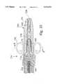
- Connectors 16, 20 and 25allow the coupling of lead 10 to the circuitry of an implanted pulse generator, such as disclosed in U.S. Pat. No. 5,007,422 to Pless et al. which is assigned to the assignee of the present invention and which is incorporated herein by reference.
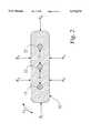
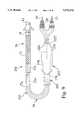
- lead 10is shown in FIG. 1 as a right ventricular transvenous defibrillation lead with dedicated bipolar sensing, for illustration purpose only, it should be understood to a person of ordinary skill in the art that the inventive design may be used universally with most implantable leads that pass through different regions of the human or animal body, for example, a lead having both RV and superior vena cava (SVC) defibrillation electrodes.
- SVCsuperior vena cava
- FIG. 9is a view of a new lead 150 employing improvements according to the present invention. Components that are common to the lead embodiment of FIG. 1 are labeled similarly in FIG. 9.
- lead 150includes a venous or heart implantable segment 152 and a clavicular segment 153 that are interconnected by means of a connector assembly 154.
- venous segment 152 and clavicular segment 153have different configurations.
- venous segment 152may have a circular cross-section and defines a central stylet lumen, while clavicular segment 153 may have a generally flattened profile without the styler lumen.
Landscapes
- Health & Medical Sciences (AREA)
- Heart & Thoracic Surgery (AREA)
- Vascular Medicine (AREA)
- Cardiology (AREA)
- Engineering & Computer Science (AREA)
- Biomedical Technology (AREA)
- Nuclear Medicine, Radiotherapy & Molecular Imaging (AREA)
- Radiology & Medical Imaging (AREA)
- Life Sciences & Earth Sciences (AREA)
- Animal Behavior & Ethology (AREA)
- General Health & Medical Sciences (AREA)
- Public Health (AREA)
- Veterinary Medicine (AREA)
- Electrotherapy Devices (AREA)
Abstract
Description
Claims (26)
Priority Applications (1)
| Application Number | Priority Date | Filing Date | Title |
|---|---|---|---|
| US08/465,155US5674272A (en) | 1995-06-05 | 1995-06-05 | Crush resistant implantable lead |
Applications Claiming Priority (1)
| Application Number | Priority Date | Filing Date | Title |
|---|---|---|---|
| US08/465,155US5674272A (en) | 1995-06-05 | 1995-06-05 | Crush resistant implantable lead |
Publications (1)
| Publication Number | Publication Date |
|---|---|
| US5674272Atrue US5674272A (en) | 1997-10-07 |
Family
ID=23846701
Family Applications (1)
| Application Number | Title | Priority Date | Filing Date |
|---|---|---|---|
| US08/465,155Expired - LifetimeUS5674272A (en) | 1995-06-05 | 1995-06-05 | Crush resistant implantable lead |
Country Status (1)
| Country | Link |
|---|---|
| US (1) | US5674272A (en) |
Cited By (87)
| Publication number | Priority date | Publication date | Assignee | Title |
|---|---|---|---|---|
| WO1998051370A1 (en)* | 1997-05-12 | 1998-11-19 | Rtc, Inc. | Electrically conductive membrane suitable for medical uses |
| US6141594A (en)* | 1998-07-22 | 2000-10-31 | Cardiac Pacemakers, Inc. | Single pass lead and system with active and passive fixation elements |
| US6212434B1 (en) | 1998-07-22 | 2001-04-03 | Cardiac Pacemakers, Inc. | Single pass lead system |
| US6256541B1 (en) | 1998-04-17 | 2001-07-03 | Cardiac Pacemakers, Inc. | Endocardial lead having defibrillation and sensing electrodes with septal anchoring |
| US6445954B1 (en) | 2000-04-04 | 2002-09-03 | Cardiac Pacemakers, Inc. | Pulse generator header lead introducer tool |
| US6456890B2 (en) | 2000-05-15 | 2002-09-24 | Pacesetter, Inc. | Lead with polymeric tubular liner for guidewire and stylet insertion |
| US6456889B2 (en) | 2000-05-15 | 2002-09-24 | Pacesetter, Inc. | Lead with polymeric tubular liner for guidewire and stylet insertion |
| US6463334B1 (en) | 1998-11-02 | 2002-10-08 | Cardiac Pacemakers, Inc. | Extendable and retractable lead |
| US20020183822A1 (en)* | 2001-05-30 | 2002-12-05 | Bodner Jeffrey P. | Extendable/retractable lead having downsized lead body |
| US6606522B2 (en) | 2001-05-30 | 2003-08-12 | Cardiac Pacemakers, Inc. | Torque mechanism and method for endocardial leads |
| US6701191B2 (en) | 2001-05-30 | 2004-03-02 | Cardiac Pacemakers, Inc. | Lead having composite tubing |
| US20040199233A1 (en)* | 2003-04-07 | 2004-10-07 | Cardiac Pacemakers, Inc. | Device and method for a self-attaching suture sleeve |
| US20040220655A1 (en)* | 2003-03-03 | 2004-11-04 | Sinus Rhythm Technologies, Inc. | Electrical conduction block implant device |
| US20040254597A1 (en)* | 2003-05-01 | 2004-12-16 | Sinus Rhythm Technologies, Inc. | Methods and devices for creating electrical block at specific targeted sites in cardiac tissue |
| US20050090820A1 (en)* | 2003-10-24 | 2005-04-28 | Sinus Rhythm Technologies, Inc. | Methods and devices for creating electrical block at specific sites in cardiac tissue with targeted tissue ablation |
| US20050131507A1 (en)* | 2003-12-11 | 2005-06-16 | Sundberg Gregory L. | Lead having reduced lead body size |
| US6983185B2 (en) | 1998-07-22 | 2006-01-03 | Cardiac Pacemakers, Inc. | Lead with terminal connector assembly |
| US20060032657A1 (en)* | 2004-08-11 | 2006-02-16 | Cardiac Pacemakers, Inc. | Lead assembly with flexible portions and method therefor |
| US20060089697A1 (en)* | 2004-10-21 | 2006-04-27 | Medtronic, Inc. | Implantable medical lead |
| US20060089695A1 (en)* | 2004-10-21 | 2006-04-27 | Medtronic, Inc. | Implantable medical lead with helical reinforcement |
| US20060089692A1 (en)* | 2004-10-21 | 2006-04-27 | Medtronic, Inc. | Implantable medical lead with stylet guide tube |
| US20060089691A1 (en)* | 2004-10-21 | 2006-04-27 | Medtronic, Inc. | Implantable medical lead with axially oriented coiled wire conductors |
| US20060116666A1 (en)* | 2004-10-08 | 2006-06-01 | Sinus Rhythm Technologies, Inc. | Two-stage scar generation for treating atrial fibrillation |
| US7097643B2 (en) | 2003-03-03 | 2006-08-29 | Sinus Rhythm Technologies, Inc. | Electrical block positioning devices and methods of use therefor |
| US20060293737A1 (en)* | 2005-06-22 | 2006-12-28 | Cardiac Pacemakers, Inc. | Multiple electrode implantable lead |
| US20070049866A1 (en)* | 2001-07-06 | 2007-03-01 | Schwartz Robert S | Anti-Arrhythmia Devices and Methods Of Use |
| WO2007053253A1 (en)* | 2005-11-07 | 2007-05-10 | Gore Enterprise Holdings, Inc. | Implantable electrophysiology lead body |
| US20070123968A1 (en)* | 2005-11-14 | 2007-05-31 | Artegraft, Inc. | Self-sealing vascular graft |
| US7245973B2 (en) | 2003-12-23 | 2007-07-17 | Cardiac Pacemakers, Inc. | His bundle mapping, pacing, and injection lead |
| US20070167901A1 (en)* | 2005-11-17 | 2007-07-19 | Herrig Judson A | Self-sealing residual compressive stress graft for dialysis |
| US20070185556A1 (en)* | 2002-04-11 | 2007-08-09 | Williams Terrell M | Medical electrical lead body designs incorporating energy dissipating shunt |
| US20070208383A1 (en)* | 2002-04-11 | 2007-09-06 | Williams Terrell M | Medical electrical lead body designs incorporating energy dissipating shunt |
| WO2009102974A1 (en) | 2008-02-15 | 2009-08-20 | Cardiac Pacemakers, Inc. | Medical electrical lead with proximal armoring |
| US20090210044A1 (en)* | 2008-02-15 | 2009-08-20 | Reddy G Shantanu | Modular, zone-specific medical electrical lead design |
| US20090254162A1 (en)* | 2004-04-23 | 2009-10-08 | Gore Enterprise Holdings, Inc. | Novel Medical Device Conductor Junctions |
| US20100121405A1 (en)* | 2008-11-10 | 2010-05-13 | Ternes David J | Distal end converter for a medical device lead |
| US20100130851A1 (en)* | 2008-11-21 | 2010-05-27 | Medtronic, Inc. | Stylet for use with image guided systems |
| US20100174350A1 (en)* | 2004-04-23 | 2010-07-08 | Medtronic, Inc. | Novel medical device conductor junctions |
| US7762977B2 (en) | 2003-10-08 | 2010-07-27 | Hemosphere, Inc. | Device and method for vascular access |
| US20100256693A1 (en)* | 2009-04-07 | 2010-10-07 | Boston Scientific Neuromodulation Corporation | Insulator layers for leads of implantable electric stimulation systems and methods of making and using |
| US20100305674A1 (en)* | 2009-05-26 | 2010-12-02 | Zarembo Paul E | Helically formed coil for a neural cuff electrode |
| US20110160819A1 (en)* | 2009-12-30 | 2011-06-30 | Kunkel Ronald W | Implantable leads with optimized lead body cross-section configuration |
| US8079973B2 (en) | 2008-03-05 | 2011-12-20 | Hemosphere Inc. | Vascular access system |
| US8204606B2 (en) | 2002-12-19 | 2012-06-19 | Cardiac Pacemakers, Inc. | Implantable lead for septal placement of pacing electrodes |
| US8257376B2 (en) | 2003-11-17 | 2012-09-04 | Syntach Ag | Device, a kit and a method for treatment of disorders in the heart rhythm regulation system |
| US8285376B2 (en) | 2004-12-20 | 2012-10-09 | Cardiac Pacemakers, Inc. | Ventricular pacing |
| US8290586B2 (en) | 2004-12-20 | 2012-10-16 | Cardiac Pacemakers, Inc. | Methods, devices and systems for single-chamber pacing using a dual-chamber pacing device |
| US8326423B2 (en) | 2004-12-20 | 2012-12-04 | Cardiac Pacemakers, Inc. | Devices and methods for steering electrical stimulation in cardiac rhythm management |
| US8406897B2 (en) | 2009-08-19 | 2013-03-26 | Boston Scientific Neuromodulation Corporation | Systems and methods for disposing one or more layers of material between lead conductor segments of electrical stimulation systems |
| US8423139B2 (en) | 2004-12-20 | 2013-04-16 | Cardiac Pacemakers, Inc. | Methods, devices and systems for cardiac rhythm management using an electrode arrangement |
| US8452406B2 (en) | 2010-09-15 | 2013-05-28 | Cardiac Pacemakers, Inc. | Automatic selection of lead configuration for a neural stimulation lead |
| US8538521B2 (en) | 2004-12-20 | 2013-09-17 | Cardiac Pacemakers, Inc. | Systems, devices and methods for monitoring efficiency of pacing |
| US8543203B2 (en) | 2004-12-20 | 2013-09-24 | Cardiac Pacemakers, Inc. | Endocardial pacing devices and methods useful for resynchronization and defibrillation |
| US8565880B2 (en) | 2010-04-27 | 2013-10-22 | Cardiac Pacemakers, Inc. | His-bundle capture verification and monitoring |
| USRE44639E1 (en) | 1997-02-07 | 2013-12-10 | Hemosphere, Inc. | Hemodialysis and vascular access system |
| US8639355B2 (en) | 2011-07-07 | 2014-01-28 | Cardiac Pacemakers, Inc. | Insulation and stability features for an implantable medical device lead |
| US8688234B2 (en) | 2008-12-19 | 2014-04-01 | Cardiac Pacemakers, Inc. | Devices, methods, and systems including cardiac pacing |
| US20140163659A1 (en)* | 2002-04-15 | 2014-06-12 | Neuropace, Inc. | Reinforced sensing and stimulation leads and use in detection systems |
| US8781599B2 (en) | 2011-08-12 | 2014-07-15 | Cochlear Limited | Flexible protected lead |
| US8812105B2 (en) | 2004-12-20 | 2014-08-19 | Cardiac Pacemakers, Inc. | Circuit-based devices and methods for pulse control of endocardial pacing in cardiac rhythm management |
| US8825155B2 (en) | 2004-12-20 | 2014-09-02 | Cardiac Pacemakers, Inc. | Systems, devices and methods relating to endocardial pacing for resynchronization |
| US8880169B2 (en) | 2004-12-20 | 2014-11-04 | Cardiac Pacemakers, Inc. | Endocardial pacing relating to conduction abnormalities |
| US8903509B2 (en) | 2012-03-21 | 2014-12-02 | Cardiac Pacemakers Inc. | Systems and methods for stimulation of vagus nerve |
| US8983626B2 (en) | 2012-12-28 | 2015-03-17 | Cardiac Pacemarkers, Inc. | Stimulation cuff and implantation tool |
| US8996114B2 (en) | 2011-06-28 | 2015-03-31 | Cardiac Pacemakers, Inc. | Strain relief feature for an implantable medical device lead |
| US20150231391A1 (en)* | 2014-02-20 | 2015-08-20 | Cardiac Pacemakers, Inc. | Apparatus for baroreceptor stimulation therapy |
| US9114250B2 (en) | 2012-10-02 | 2015-08-25 | Cardiac Pacemakers, Inc. | Pinch to open cuff electrode |
| US9278172B2 (en) | 2011-09-06 | 2016-03-08 | Cryolife, Inc. | Vascular access system with connector |
| US9283379B2 (en) | 2012-10-02 | 2016-03-15 | Cardiac Pacemakers, Inc. | Pinch to open cuff electrode |
| US9320889B2 (en) | 2013-02-13 | 2016-04-26 | Cardiac Pacemakers, Inc. | Cuff electrode with integrated tendril |
| US9398967B2 (en) | 2004-03-02 | 2016-07-26 | Syntach Ag | Electrical conduction block implant device |
| US20170189674A1 (en)* | 2016-01-04 | 2017-07-06 | Medtronic, Inc. | Medical electrical lead |
| US9795778B2 (en) | 2013-07-14 | 2017-10-24 | Cardiac Pacemakers, Inc. | Multi-electrode lead with backing for mecho/baroreceptor stimulation |
| US9839785B2 (en) | 2013-12-13 | 2017-12-12 | Cardiac Pacemakers, Inc. | Surgical instrument for implanting leads for baroreceptor stimulation therapy |
| US10080862B2 (en) | 2015-08-14 | 2018-09-25 | Medtronic, Inc. | Tubular bodies for medical delivery devices and related manufacturing methods |
| US10682453B2 (en) | 2013-12-20 | 2020-06-16 | Merit Medical Systems, Inc. | Vascular access system with reinforcement member |
| US10792413B2 (en) | 2008-03-05 | 2020-10-06 | Merit Medical Systems, Inc. | Implantable and removable customizable body conduit |
| US10925710B2 (en) | 2017-03-24 | 2021-02-23 | Merit Medical Systems, Inc. | Subcutaneous vascular assemblies for improving blood flow and related devices and methods |
| US11026704B2 (en) | 2017-03-06 | 2021-06-08 | Merit Medical Systems, Inc. | Vascular access assembly declotting systems and methods |
| US11173299B2 (en) | 2018-12-03 | 2021-11-16 | Advanced Bionics Ag | Electrode leads configured to engage with a fixing element and methods for manufacturing the same |
| US11179543B2 (en) | 2017-07-14 | 2021-11-23 | Merit Medical Systems, Inc. | Releasable conduit connectors |
| US11331458B2 (en) | 2017-10-31 | 2022-05-17 | Merit Medical Systems, Inc. | Subcutaneous vascular assemblies for improving blood flow and related devices and methods |
| US11383072B2 (en) | 2017-01-12 | 2022-07-12 | Merit Medical Systems, Inc. | Methods and systems for selection and use of connectors between conduits |
| US11413043B2 (en) | 2016-11-10 | 2022-08-16 | Merit Medical Systems, Inc. | Anchor device for vascular anastomosis |
| US11590010B2 (en) | 2017-01-25 | 2023-02-28 | Merit Medical Systems, Inc. | Methods and systems for facilitating laminar flow between conduits |
| US11691003B2 (en) | 2018-07-23 | 2023-07-04 | Advanced Bionics Ag | Reinforced electrode leads and methods for manufacturing the same |
| US11911585B2 (en) | 2017-07-20 | 2024-02-27 | Merit Medical Systems, Inc. | Methods and systems for coupling conduits |
Citations (23)
| Publication number | Priority date | Publication date | Assignee | Title |
|---|---|---|---|---|
| US3405715A (en)* | 1966-10-20 | 1968-10-15 | Medtronic Inc | Implantable electrode |
| US3572344A (en)* | 1968-12-31 | 1971-03-23 | Medtronic Inc | Electrode apparatus with lead construction |
| US3724467A (en)* | 1971-04-23 | 1973-04-03 | Avery Labor Inc | Electrode implant for the neuro-stimulation of the spinal cord |
| US3788329A (en)* | 1972-04-17 | 1974-01-29 | Medtronic Inc | Body implantable lead |
| US4422460A (en)* | 1982-04-08 | 1983-12-27 | Cordis Corporation | Positionable locating and orienting wing for a pacing lead |
| US4469104A (en)* | 1982-07-16 | 1984-09-04 | Cordis Corporation | Multipolar connector for pacing lead |
| US4573480A (en)* | 1983-02-16 | 1986-03-04 | Siemens Aktiengesellschaft | Implantable electrode lead with microporous insulation |
| US4603705A (en)* | 1984-05-04 | 1986-08-05 | Mieczyslaw Mirowski | Intravascular multiple electrode unitary catheter |
| US4608986A (en)* | 1984-10-01 | 1986-09-02 | Cordis Corporation | Pacing lead with straight wire conductors |
| US4630611A (en)* | 1981-02-02 | 1986-12-23 | Medtronic, Inc. | Orthogonally-sensing lead |
| US4954105A (en)* | 1989-12-28 | 1990-09-04 | Intermedics, Inc. | Replacement connector for implanted leads |
| US5007435A (en)* | 1988-05-25 | 1991-04-16 | Medtronic, Inc. | Connector for multiconductor pacing leads |
| US5007422A (en)* | 1989-06-06 | 1991-04-16 | Ventritex, Inc. | Method for combiner cardiac pacing and defibrillation |
| US5044375A (en)* | 1989-12-08 | 1991-09-03 | Cardiac Pacemakers, Inc. | Unitary intravascular defibrillating catheter with separate bipolar sensing |
| US5095903A (en)* | 1987-01-29 | 1992-03-17 | P.A. & M. S.P.A. | Epi-cardial electrode with an incorporated cardiac radio-frequency receiver (C&R) for temporary heart stimulation from the outside, prearranged for permanent stimulation |
| US5246014A (en)* | 1991-11-08 | 1993-09-21 | Medtronic, Inc. | Implantable lead system |
| US5324321A (en)* | 1992-12-22 | 1994-06-28 | Medtronic, Inc. | Medical electrical lead having sigmoidal conductors and non-circular lumens |
| US5330523A (en)* | 1992-08-05 | 1994-07-19 | Siemens Pacesetter, Inc. | Implantable defibrillator patch lead |
| US5358516A (en)* | 1992-12-11 | 1994-10-25 | W. L. Gore & Associates, Inc. | Implantable electrophysiology lead and method of making |
| US5466253A (en)* | 1993-04-27 | 1995-11-14 | Pacesetter, Inc. | Crush resistant multi-conductor lead body |
| US5466252A (en)* | 1992-10-02 | 1995-11-14 | W. L. Gore & Associates, Inc. | Implantable lead |
| US5476497A (en)* | 1991-01-09 | 1995-12-19 | Ann Mirowski | Oval electrode lead body |
| US5584873A (en)* | 1995-05-08 | 1996-12-17 | Medtronic, Inc. | Medical lead with compression lumens |
- 1995
- 1995-06-05USUS08/465,155patent/US5674272A/ennot_activeExpired - Lifetime
Patent Citations (24)
| Publication number | Priority date | Publication date | Assignee | Title |
|---|---|---|---|---|
| US3405715A (en)* | 1966-10-20 | 1968-10-15 | Medtronic Inc | Implantable electrode |
| US3572344A (en)* | 1968-12-31 | 1971-03-23 | Medtronic Inc | Electrode apparatus with lead construction |
| US3724467A (en)* | 1971-04-23 | 1973-04-03 | Avery Labor Inc | Electrode implant for the neuro-stimulation of the spinal cord |
| US3788329A (en)* | 1972-04-17 | 1974-01-29 | Medtronic Inc | Body implantable lead |
| US4630611A (en)* | 1981-02-02 | 1986-12-23 | Medtronic, Inc. | Orthogonally-sensing lead |
| US4422460A (en)* | 1982-04-08 | 1983-12-27 | Cordis Corporation | Positionable locating and orienting wing for a pacing lead |
| US4469104A (en)* | 1982-07-16 | 1984-09-04 | Cordis Corporation | Multipolar connector for pacing lead |
| US4573480A (en)* | 1983-02-16 | 1986-03-04 | Siemens Aktiengesellschaft | Implantable electrode lead with microporous insulation |
| US4603705A (en)* | 1984-05-04 | 1986-08-05 | Mieczyslaw Mirowski | Intravascular multiple electrode unitary catheter |
| US4608986A (en)* | 1984-10-01 | 1986-09-02 | Cordis Corporation | Pacing lead with straight wire conductors |
| US5095903A (en)* | 1987-01-29 | 1992-03-17 | P.A. & M. S.P.A. | Epi-cardial electrode with an incorporated cardiac radio-frequency receiver (C&R) for temporary heart stimulation from the outside, prearranged for permanent stimulation |
| US5007435A (en)* | 1988-05-25 | 1991-04-16 | Medtronic, Inc. | Connector for multiconductor pacing leads |
| US5007422A (en)* | 1989-06-06 | 1991-04-16 | Ventritex, Inc. | Method for combiner cardiac pacing and defibrillation |
| US5044375A (en)* | 1989-12-08 | 1991-09-03 | Cardiac Pacemakers, Inc. | Unitary intravascular defibrillating catheter with separate bipolar sensing |
| US4954105A (en)* | 1989-12-28 | 1990-09-04 | Intermedics, Inc. | Replacement connector for implanted leads |
| US5476497A (en)* | 1991-01-09 | 1995-12-19 | Ann Mirowski | Oval electrode lead body |
| US5246014A (en)* | 1991-11-08 | 1993-09-21 | Medtronic, Inc. | Implantable lead system |
| US5330523A (en)* | 1992-08-05 | 1994-07-19 | Siemens Pacesetter, Inc. | Implantable defibrillator patch lead |
| US5466252A (en)* | 1992-10-02 | 1995-11-14 | W. L. Gore & Associates, Inc. | Implantable lead |
| US5358516A (en)* | 1992-12-11 | 1994-10-25 | W. L. Gore & Associates, Inc. | Implantable electrophysiology lead and method of making |
| US5324321A (en)* | 1992-12-22 | 1994-06-28 | Medtronic, Inc. | Medical electrical lead having sigmoidal conductors and non-circular lumens |
| US5466253A (en)* | 1993-04-27 | 1995-11-14 | Pacesetter, Inc. | Crush resistant multi-conductor lead body |
| US5545203A (en)* | 1993-04-27 | 1996-08-13 | Pacesetter, Inc. | Crush resistant multi-conductor lead body |
| US5584873A (en)* | 1995-05-08 | 1996-12-17 | Medtronic, Inc. | Medical lead with compression lumens |
Non-Patent Citations (12)
| Title |
|---|
| "Anatomical and Morphological Evaluation of Pacemaker Lead Compression", Jacobs, et al., PACE, vol. 16, Part I, Mar. 1993, pp. 434-444. |
| "Anatomical Mechanisms Explaining Damage to Pacemaker Leads, Defibrillator Leads, and Failure of Central Venous Catheters Adjacent to the Sternoclavicular Joint", Magney, et al., PACE, vol. 16, Part I, Mar. 1993, pp. 445-457. |
| "Initial Experience with a New Co-Radial Bipolar Pacing Lead", Tang, et al., NASPE Abstract No. 296, PACE, vol. 18, Part II, Apr. 1995, p. 869. |
| "Suture Induced Lead Deformity", Maloney, III, et al., NASPE Abstract No. 294, PACE, vol. 18, Part II, Apr. 1995, p. 869. |
| "Thin Bipolar Leads: A Solution to Problems with Coaxial Bipolar Designs", Adler, et al., PACE, vol. 15, Part II, Nov. 1992, pp. 1986-1990. |
| Anatomical and Morphological Evaluation of Pacemaker Lead Compression , Jacobs, et al., PACE, vol. 16, Part I, Mar. 1993, pp. 434 444.* |
| Anatomical Mechanisms Explaining Damage to Pacemaker Leads, Defibrillator Leads, and Failure of Central Venous Catheters Adjacent to the Sternoclavicular Joint , Magney, et al., PACE, vol. 16, Part I, Mar. 1993, pp. 445 457.* |
| Initial Experience with a New Co Radial Bipolar Pacing Lead , Tang, et al., NASPE Abstract No. 296, PACE, vol. 18, Part II, Apr. 1995, p. 869.* |
| Suture Induced Lead Deformity , Maloney, III, et al., NASPE Abstract No. 294, PACE, vol. 18, Part II, Apr. 1995, p. 869.* |
| Thin Bipolar Leads: A Solution to Problems with Coaxial Bipolar Designs , Adler, et al., PACE, vol. 15, Part II, Nov. 1992, pp. 1986 1990.* |
| U.S. Patent Application No. 08/015,684 entitled "Lead Adapter", McEtchin, et al., Feb. 9, 1993, Ventritex, Inc. |
| U.S. Patent Application No. 08/015,684 entitled Lead Adapter , McEtchin, et al., Feb. 9, 1993, Ventritex, Inc.* |
Cited By (165)
| Publication number | Priority date | Publication date | Assignee | Title |
|---|---|---|---|---|
| USRE44639E1 (en) | 1997-02-07 | 2013-12-10 | Hemosphere, Inc. | Hemodialysis and vascular access system |
| US6007488A (en)* | 1997-05-12 | 1999-12-28 | Rtc, Inc. | Medical probe including an electrically conductive membrane suitable for medical uses |
| WO1998051370A1 (en)* | 1997-05-12 | 1998-11-19 | Rtc, Inc. | Electrically conductive membrane suitable for medical uses |
| US6256541B1 (en) | 1998-04-17 | 2001-07-03 | Cardiac Pacemakers, Inc. | Endocardial lead having defibrillation and sensing electrodes with septal anchoring |
| US6983185B2 (en) | 1998-07-22 | 2006-01-03 | Cardiac Pacemakers, Inc. | Lead with terminal connector assembly |
| US8285398B2 (en) | 1998-07-22 | 2012-10-09 | Cardiac Pacemakers, Inc. | Lead with terminal connector assembly |
| US7392095B2 (en) | 1998-07-22 | 2008-06-24 | Cardiac Pacemakers, Inc. | Extendable and retractable lead having a snap-fit terminal connector |
| US6505082B1 (en) | 1998-07-22 | 2003-01-07 | Cardiac Pacemakers, Inc. | Single pass lead system |
| US6141594A (en)* | 1998-07-22 | 2000-10-31 | Cardiac Pacemakers, Inc. | Single pass lead and system with active and passive fixation elements |
| US6212434B1 (en) | 1998-07-22 | 2001-04-03 | Cardiac Pacemakers, Inc. | Single pass lead system |
| US8209035B2 (en) | 1998-07-22 | 2012-06-26 | Cardiac Pacemakers, Inc. | Extendable and retractable lead having a snap-fit terminal connector |
| US6915169B2 (en) | 1998-07-22 | 2005-07-05 | Cardiac Pacemakers, Inc. | Extendable and retractable lead having a snap-fit terminal connector |
| US7774934B2 (en) | 1998-07-22 | 2010-08-17 | Cardiac Pacemakers, Inc. | Method for making a terminal connector |
| US6463334B1 (en) | 1998-11-02 | 2002-10-08 | Cardiac Pacemakers, Inc. | Extendable and retractable lead |
| US6445954B1 (en) | 2000-04-04 | 2002-09-03 | Cardiac Pacemakers, Inc. | Pulse generator header lead introducer tool |
| US6456890B2 (en) | 2000-05-15 | 2002-09-24 | Pacesetter, Inc. | Lead with polymeric tubular liner for guidewire and stylet insertion |
| US6456889B2 (en) | 2000-05-15 | 2002-09-24 | Pacesetter, Inc. | Lead with polymeric tubular liner for guidewire and stylet insertion |
| US7257449B2 (en) | 2001-05-30 | 2007-08-14 | Cardiac Pacemakers, Inc. | Extendable/retractable lead having downsized lead body |
| US6606522B2 (en) | 2001-05-30 | 2003-08-12 | Cardiac Pacemakers, Inc. | Torque mechanism and method for endocardial leads |
| US20040230277A1 (en)* | 2001-05-30 | 2004-11-18 | Cardiac Pacemakers, Inc. | Lead having composite tubing |
| US20020183822A1 (en)* | 2001-05-30 | 2002-12-05 | Bodner Jeffrey P. | Extendable/retractable lead having downsized lead body |
| US20080011504A1 (en)* | 2001-05-30 | 2008-01-17 | Cardiac Pacemakers, Inc. | Extendable/retractable lead having downsized lead body |
| US20080132984A1 (en)* | 2001-05-30 | 2008-06-05 | Cardiac Pacemakers, Inc. | Lead having composite insulative coating |
| US7337009B2 (en) | 2001-05-30 | 2008-02-26 | Cardiac Pacemakers, Inc. | Lead having composite tubing |
| US8046084B2 (en) | 2001-05-30 | 2011-10-25 | Cardiac Pacemakers, Inc. | Extendable/retractable lead having downsized lead body |
| US6701191B2 (en) | 2001-05-30 | 2004-03-02 | Cardiac Pacemakers, Inc. | Lead having composite tubing |
| US8579955B2 (en) | 2001-07-06 | 2013-11-12 | Syntach Ag | Anti-arrhythmia devices and methods of use |
| US20070049866A1 (en)* | 2001-07-06 | 2007-03-01 | Schwartz Robert S | Anti-Arrhythmia Devices and Methods Of Use |
| US7904178B2 (en) | 2002-04-11 | 2011-03-08 | Medtronic, Inc. | Medical electrical lead body designs incorporating energy dissipating shunt |
| US8396568B2 (en) | 2002-04-11 | 2013-03-12 | Medtronic, Inc. | Medical electrical lead body designs incorporating energy dissipating shunt |
| US20070208383A1 (en)* | 2002-04-11 | 2007-09-06 | Williams Terrell M | Medical electrical lead body designs incorporating energy dissipating shunt |
| US20070185556A1 (en)* | 2002-04-11 | 2007-08-09 | Williams Terrell M | Medical electrical lead body designs incorporating energy dissipating shunt |
| US20140163659A1 (en)* | 2002-04-15 | 2014-06-12 | Neuropace, Inc. | Reinforced sensing and stimulation leads and use in detection systems |
| US9162050B2 (en)* | 2002-04-15 | 2015-10-20 | Neuropace, Inc. | Reinforced sensing and stimulation leads and use in detection systems |
| US8204606B2 (en) | 2002-12-19 | 2012-06-19 | Cardiac Pacemakers, Inc. | Implantable lead for septal placement of pacing electrodes |
| US20090171445A1 (en)* | 2003-03-03 | 2009-07-02 | William Swanson | Electrical Conduction Block Implant Device |
| US20090171431A1 (en)* | 2003-03-03 | 2009-07-02 | William Swanson | Electrical Conduction Block Implant Device |
| US20060247607A1 (en)* | 2003-03-03 | 2006-11-02 | Richard Cornelius | Electrical Block Positioning Devices And Methods Of Use therefor |
| US7097643B2 (en) | 2003-03-03 | 2006-08-29 | Sinus Rhythm Technologies, Inc. | Electrical block positioning devices and methods of use therefor |
| US8840658B2 (en) | 2003-03-03 | 2014-09-23 | Syntach Ag | Electrical conduction block implant device |
| US20040220655A1 (en)* | 2003-03-03 | 2004-11-04 | Sinus Rhythm Technologies, Inc. | Electrical conduction block implant device |
| US8409268B2 (en) | 2003-03-03 | 2013-04-02 | Syntach Ag | Electrical conduction block implant device |
| US7242986B2 (en)* | 2003-04-07 | 2007-07-10 | Cardiac Pacemakers, Inc. | Device and method for a self-attaching suture sleeve |
| US20040199233A1 (en)* | 2003-04-07 | 2004-10-07 | Cardiac Pacemakers, Inc. | Device and method for a self-attaching suture sleeve |
| US20100174304A1 (en)* | 2003-05-01 | 2010-07-08 | Schwartz Robert S | Methods And Devices For Creating Electrical Block At Specific Targeted Sites In Cardiac Tissue |
| US20040254597A1 (en)* | 2003-05-01 | 2004-12-16 | Sinus Rhythm Technologies, Inc. | Methods and devices for creating electrical block at specific targeted sites in cardiac tissue |
| US7762977B2 (en) | 2003-10-08 | 2010-07-27 | Hemosphere, Inc. | Device and method for vascular access |
| US20110060264A1 (en)* | 2003-10-08 | 2011-03-10 | Hemosphere Inc. | Device and method for vascular access |
| USRE47154E1 (en) | 2003-10-08 | 2018-12-11 | Merit Medical Systems, Inc. | Device and method for vascular access |
| US8690815B2 (en) | 2003-10-08 | 2014-04-08 | Hemosphere, Inc. | Device and method for vascular access |
| US20050090820A1 (en)* | 2003-10-24 | 2005-04-28 | Sinus Rhythm Technologies, Inc. | Methods and devices for creating electrical block at specific sites in cardiac tissue with targeted tissue ablation |
| US7266414B2 (en) | 2003-10-24 | 2007-09-04 | Syntach, Ag | Methods and devices for creating electrical block at specific sites in cardiac tissue with targeted tissue ablation |
| US8257376B2 (en) | 2003-11-17 | 2012-09-04 | Syntach Ag | Device, a kit and a method for treatment of disorders in the heart rhythm regulation system |
| US9295484B2 (en) | 2003-11-17 | 2016-03-29 | Syntach Ag | Device, a kit and a method for treatment of disorders in the heart rhythm regulation system |
| US20050131507A1 (en)* | 2003-12-11 | 2005-06-16 | Sundberg Gregory L. | Lead having reduced lead body size |
| US7245973B2 (en) | 2003-12-23 | 2007-07-17 | Cardiac Pacemakers, Inc. | His bundle mapping, pacing, and injection lead |
| US8078287B2 (en) | 2003-12-23 | 2011-12-13 | Cardiac Pacemakers, Inc. | His bundle mapping, pacing, and injection lead |
| US9398967B2 (en) | 2004-03-02 | 2016-07-26 | Syntach Ag | Electrical conduction block implant device |
| US8271100B2 (en) | 2004-04-23 | 2012-09-18 | Medtronic, Inc. | Medical device conductor junctions |
| US20090254162A1 (en)* | 2004-04-23 | 2009-10-08 | Gore Enterprise Holdings, Inc. | Novel Medical Device Conductor Junctions |
| US20100174350A1 (en)* | 2004-04-23 | 2010-07-08 | Medtronic, Inc. | Novel medical device conductor junctions |
| US20060032657A1 (en)* | 2004-08-11 | 2006-02-16 | Cardiac Pacemakers, Inc. | Lead assembly with flexible portions and method therefor |
| US7238883B2 (en) | 2004-08-11 | 2007-07-03 | Cardiac Pacemakers, Inc. | Lead assembly with flexible portions and method therefor |
| US7807925B2 (en) | 2004-08-11 | 2010-10-05 | Cardiac Pacemakers, Inc. | Lead assembly with flexible portions and method therefor |
| US20060116666A1 (en)* | 2004-10-08 | 2006-06-01 | Sinus Rhythm Technologies, Inc. | Two-stage scar generation for treating atrial fibrillation |
| US20060089692A1 (en)* | 2004-10-21 | 2006-04-27 | Medtronic, Inc. | Implantable medical lead with stylet guide tube |
| US7519432B2 (en) | 2004-10-21 | 2009-04-14 | Medtronic, Inc. | Implantable medical lead with helical reinforcement |
| US20060089691A1 (en)* | 2004-10-21 | 2006-04-27 | Medtronic, Inc. | Implantable medical lead with axially oriented coiled wire conductors |
| US7761170B2 (en) | 2004-10-21 | 2010-07-20 | Medtronic, Inc. | Implantable medical lead with axially oriented coiled wire conductors |
| US7831311B2 (en) | 2004-10-21 | 2010-11-09 | Medtronic, Inc. | Reduced axial stiffness implantable medical lead |
| US20060089697A1 (en)* | 2004-10-21 | 2006-04-27 | Medtronic, Inc. | Implantable medical lead |
| US20060089695A1 (en)* | 2004-10-21 | 2006-04-27 | Medtronic, Inc. | Implantable medical lead with helical reinforcement |
| US8934969B2 (en) | 2004-12-20 | 2015-01-13 | Cardiac Pacemakers, Inc. | Systems, devices and methods for monitoring efficiency of pacing |
| US8285376B2 (en) | 2004-12-20 | 2012-10-09 | Cardiac Pacemakers, Inc. | Ventricular pacing |
| US8538521B2 (en) | 2004-12-20 | 2013-09-17 | Cardiac Pacemakers, Inc. | Systems, devices and methods for monitoring efficiency of pacing |
| US8812105B2 (en) | 2004-12-20 | 2014-08-19 | Cardiac Pacemakers, Inc. | Circuit-based devices and methods for pulse control of endocardial pacing in cardiac rhythm management |
| US8437848B2 (en) | 2004-12-20 | 2013-05-07 | Cardiac Pacemakers, Inc. | Apparatus for treating the physiological electric conduction of the heart |
| US8428715B2 (en) | 2004-12-20 | 2013-04-23 | Cardiac Pacemakers, Inc. | Methods for treating the physiological electric conduction of the heart |
| US9031648B2 (en) | 2004-12-20 | 2015-05-12 | Cardiac Pacemakers, Inc. | Endocardial pacing devices and methods useful for resynchronization and defibrillation |
| US9008768B2 (en) | 2004-12-20 | 2015-04-14 | Cardiac Pacemakers, Inc. | Methods, devices and systems for cardiac rhythm management using an electrode arrangement |
| US8423139B2 (en) | 2004-12-20 | 2013-04-16 | Cardiac Pacemakers, Inc. | Methods, devices and systems for cardiac rhythm management using an electrode arrangement |
| US8903489B2 (en) | 2004-12-20 | 2014-12-02 | Cardiac Pacemakers, Inc. | Methods, devices and systems for single-chamber pacing using a dual-chamber pacing device |
| US8880169B2 (en) | 2004-12-20 | 2014-11-04 | Cardiac Pacemakers, Inc. | Endocardial pacing relating to conduction abnormalities |
| US8812106B2 (en) | 2004-12-20 | 2014-08-19 | Cardiac Pacemakers, Inc. | Apparatus for treating the physiological electric conduction of the heart |
| US8825155B2 (en) | 2004-12-20 | 2014-09-02 | Cardiac Pacemakers, Inc. | Systems, devices and methods relating to endocardial pacing for resynchronization |
| US8346358B2 (en) | 2004-12-20 | 2013-01-01 | Cardiac Pacemakers, Inc. | Pacemaker which reestablishes or keeps the physiological electric conduction of the heart and a method of application |
| US8838238B2 (en) | 2004-12-20 | 2014-09-16 | Cardiac Pacemakers, Inc. | Ventricular pacing |
| US8825159B2 (en) | 2004-12-20 | 2014-09-02 | Cardiac Pacemakers, Inc. | Devices and methods for steering electrical stimulation in cardiac rhythm management |
| US8326423B2 (en) | 2004-12-20 | 2012-12-04 | Cardiac Pacemakers, Inc. | Devices and methods for steering electrical stimulation in cardiac rhythm management |
| US8543203B2 (en) | 2004-12-20 | 2013-09-24 | Cardiac Pacemakers, Inc. | Endocardial pacing devices and methods useful for resynchronization and defibrillation |
| US8290586B2 (en) | 2004-12-20 | 2012-10-16 | Cardiac Pacemakers, Inc. | Methods, devices and systems for single-chamber pacing using a dual-chamber pacing device |
| US20060293737A1 (en)* | 2005-06-22 | 2006-12-28 | Cardiac Pacemakers, Inc. | Multiple electrode implantable lead |
| US20070106144A1 (en)* | 2005-11-07 | 2007-05-10 | John Squeri | Implantable electrophysiology lead body |
| WO2007133253A1 (en)* | 2005-11-07 | 2007-11-22 | Gore Enterprise Holdings, Inc. | Implantable electrophysiology lead body |
| US7630749B2 (en)* | 2005-11-07 | 2009-12-08 | Gore Enterprise Holdings, Inc. | Implantable electrophysiology lead body |
| AU2006343538B2 (en)* | 2005-11-07 | 2010-09-23 | W. L. Gore & Associates, Inc. | Implantable electrophysiology lead body |
| US8437830B2 (en)* | 2005-11-07 | 2013-05-07 | W. L. Gore & Associates, Inc. | Implantable electrophysiology lead body |
| US20100042192A1 (en)* | 2005-11-07 | 2010-02-18 | John Squeri | Implantable Electrophysiology Lead Body |
| US8442612B2 (en)* | 2005-11-07 | 2013-05-14 | W. L. Gore & Associates, Inc. | Implantable electrophysiology lead body |
| WO2007053253A1 (en)* | 2005-11-07 | 2007-05-10 | Gore Enterprise Holdings, Inc. | Implantable electrophysiology lead body |
| US20090125089A1 (en)* | 2005-11-07 | 2009-05-14 | Bischoff Thomas C | Implantable Electrophysiology Lead Body |
| US20100042191A1 (en)* | 2005-11-07 | 2010-02-18 | John Squeri | Implantable Electrophysiology Lead Body |
| US8163002B2 (en) | 2005-11-14 | 2012-04-24 | Vascular Devices Llc | Self-sealing vascular graft |
| US20070123968A1 (en)* | 2005-11-14 | 2007-05-31 | Artegraft, Inc. | Self-sealing vascular graft |
| US20070167901A1 (en)* | 2005-11-17 | 2007-07-19 | Herrig Judson A | Self-sealing residual compressive stress graft for dialysis |
| WO2009102972A1 (en)* | 2008-02-15 | 2009-08-20 | Cardiac Pacemakers, Inc. | Modular, zone-specific medical electrical lead design |
| JP2011512200A (en)* | 2008-02-15 | 2011-04-21 | カーディアック ペースメイカーズ, インコーポレイテッド | Medical electrical lead with proximal protection |
| US8099175B2 (en) | 2008-02-15 | 2012-01-17 | Cardiac Pacemakers, Inc. | Medical electrical lead with proximal armoring |
| US20090210043A1 (en)* | 2008-02-15 | 2009-08-20 | Reddy G Shantanu | Medical electrical lead with proximal armoring |
| US20090210044A1 (en)* | 2008-02-15 | 2009-08-20 | Reddy G Shantanu | Modular, zone-specific medical electrical lead design |
| US20110197440A1 (en)* | 2008-02-15 | 2011-08-18 | Reddy G Shantanu | Modular, zone-specific medical electrical lead design |
| JP2011512199A (en)* | 2008-02-15 | 2011-04-21 | カーディアック ペースメイカーズ, インコーポレイテッド | Modular zoned medical electrical lead design |
| WO2009102974A1 (en) | 2008-02-15 | 2009-08-20 | Cardiac Pacemakers, Inc. | Medical electrical lead with proximal armoring |
| US7946980B2 (en) | 2008-02-15 | 2011-05-24 | Cardiac Pacemakers, Inc. | Modular, zone-specific medical electrical lead design |
| US8099176B2 (en) | 2008-02-15 | 2012-01-17 | Cardiac Pacemakers, Inc. | Modular, zone-specific medical electrical lead design |
| US8079973B2 (en) | 2008-03-05 | 2011-12-20 | Hemosphere Inc. | Vascular access system |
| US10792413B2 (en) | 2008-03-05 | 2020-10-06 | Merit Medical Systems, Inc. | Implantable and removable customizable body conduit |
| US20100121405A1 (en)* | 2008-11-10 | 2010-05-13 | Ternes David J | Distal end converter for a medical device lead |
| US8548593B2 (en) | 2008-11-10 | 2013-10-01 | Cardiac Pacemakers, Inc. | Distal end converter for a medical device lead |
| US20100130851A1 (en)* | 2008-11-21 | 2010-05-27 | Medtronic, Inc. | Stylet for use with image guided systems |
| US8204574B2 (en)* | 2008-11-21 | 2012-06-19 | Medtronic, Inc. | Stylet for use with image guided systems |
| US8688234B2 (en) | 2008-12-19 | 2014-04-01 | Cardiac Pacemakers, Inc. | Devices, methods, and systems including cardiac pacing |
| US8478423B2 (en)* | 2009-04-07 | 2013-07-02 | Boston Scientific Neuromodulation Corporation | Insulator layers for leads of implantable electric stimulation systems and methods of making and using |
| US20100256693A1 (en)* | 2009-04-07 | 2010-10-07 | Boston Scientific Neuromodulation Corporation | Insulator layers for leads of implantable electric stimulation systems and methods of making and using |
| US20100305674A1 (en)* | 2009-05-26 | 2010-12-02 | Zarembo Paul E | Helically formed coil for a neural cuff electrode |
| US8954167B2 (en)* | 2009-05-26 | 2015-02-10 | Cardiac Pacemakers, Inc. | Helically formed coil for a neural cuff electrode |
| US8406897B2 (en) | 2009-08-19 | 2013-03-26 | Boston Scientific Neuromodulation Corporation | Systems and methods for disposing one or more layers of material between lead conductor segments of electrical stimulation systems |
| US20110160819A1 (en)* | 2009-12-30 | 2011-06-30 | Kunkel Ronald W | Implantable leads with optimized lead body cross-section configuration |
| US8983622B2 (en) | 2009-12-30 | 2015-03-17 | Cardiac Pacemakers, Inc. | Implantable leads with optimized lead body cross-section configuration |
| US8565880B2 (en) | 2010-04-27 | 2013-10-22 | Cardiac Pacemakers, Inc. | His-bundle capture verification and monitoring |
| US9731135B2 (en) | 2010-09-15 | 2017-08-15 | Cardiac Pacemakers, Inc. | Automatic selection of lead configuration for a neural stimulation lead |
| US9050472B2 (en) | 2010-09-15 | 2015-06-09 | Cardiac Pacemakers, Inc. | Automatic selection of lead configuration for a neural stimulation lead |
| US8452406B2 (en) | 2010-09-15 | 2013-05-28 | Cardiac Pacemakers, Inc. | Automatic selection of lead configuration for a neural stimulation lead |
| US8996114B2 (en) | 2011-06-28 | 2015-03-31 | Cardiac Pacemakers, Inc. | Strain relief feature for an implantable medical device lead |
| US8639355B2 (en) | 2011-07-07 | 2014-01-28 | Cardiac Pacemakers, Inc. | Insulation and stability features for an implantable medical device lead |
| US8781599B2 (en) | 2011-08-12 | 2014-07-15 | Cochlear Limited | Flexible protected lead |
| US9278172B2 (en) | 2011-09-06 | 2016-03-08 | Cryolife, Inc. | Vascular access system with connector |
| US11185676B2 (en) | 2011-09-06 | 2021-11-30 | Merit Medical Systems, Inc. | Vascular access system with connector |
| US10632296B2 (en) | 2011-09-06 | 2020-04-28 | Merit Medical Systems, Inc. | Vascular access system with connector |
| US10213590B2 (en) | 2011-09-06 | 2019-02-26 | Merit Medical Systems, Inc. | Vascular access system with connector |
| US8903509B2 (en) | 2012-03-21 | 2014-12-02 | Cardiac Pacemakers Inc. | Systems and methods for stimulation of vagus nerve |
| US9114250B2 (en) | 2012-10-02 | 2015-08-25 | Cardiac Pacemakers, Inc. | Pinch to open cuff electrode |
| US9283379B2 (en) | 2012-10-02 | 2016-03-15 | Cardiac Pacemakers, Inc. | Pinch to open cuff electrode |
| US8983626B2 (en) | 2012-12-28 | 2015-03-17 | Cardiac Pacemarkers, Inc. | Stimulation cuff and implantation tool |
| US9320889B2 (en) | 2013-02-13 | 2016-04-26 | Cardiac Pacemakers, Inc. | Cuff electrode with integrated tendril |
| US9452283B2 (en) | 2013-02-13 | 2016-09-27 | Cardiac Pacemakers, Inc. | Cuff electrode with integrated tendril |
| US9795778B2 (en) | 2013-07-14 | 2017-10-24 | Cardiac Pacemakers, Inc. | Multi-electrode lead with backing for mecho/baroreceptor stimulation |
| US9839785B2 (en) | 2013-12-13 | 2017-12-12 | Cardiac Pacemakers, Inc. | Surgical instrument for implanting leads for baroreceptor stimulation therapy |
| US10682453B2 (en) | 2013-12-20 | 2020-06-16 | Merit Medical Systems, Inc. | Vascular access system with reinforcement member |
| US10029091B2 (en)* | 2014-02-20 | 2018-07-24 | Cardiac Pacemakers, Inc. | Apparatus for baroreceptor stimulation therapy |
| US20150231391A1 (en)* | 2014-02-20 | 2015-08-20 | Cardiac Pacemakers, Inc. | Apparatus for baroreceptor stimulation therapy |
| US10080862B2 (en) | 2015-08-14 | 2018-09-25 | Medtronic, Inc. | Tubular bodies for medical delivery devices and related manufacturing methods |
| US20170189674A1 (en)* | 2016-01-04 | 2017-07-06 | Medtronic, Inc. | Medical electrical lead |
| US11413043B2 (en) | 2016-11-10 | 2022-08-16 | Merit Medical Systems, Inc. | Anchor device for vascular anastomosis |
| US11383072B2 (en) | 2017-01-12 | 2022-07-12 | Merit Medical Systems, Inc. | Methods and systems for selection and use of connectors between conduits |
| US11590010B2 (en) | 2017-01-25 | 2023-02-28 | Merit Medical Systems, Inc. | Methods and systems for facilitating laminar flow between conduits |
| US11026704B2 (en) | 2017-03-06 | 2021-06-08 | Merit Medical Systems, Inc. | Vascular access assembly declotting systems and methods |
| US10925710B2 (en) | 2017-03-24 | 2021-02-23 | Merit Medical Systems, Inc. | Subcutaneous vascular assemblies for improving blood flow and related devices and methods |
| US11622846B2 (en) | 2017-03-24 | 2023-04-11 | Merit Medical Systems, Inc. | Subcutaneous vascular assemblies for improving blood flow and related devices and methods |
| US11179543B2 (en) | 2017-07-14 | 2021-11-23 | Merit Medical Systems, Inc. | Releasable conduit connectors |
| US11911585B2 (en) | 2017-07-20 | 2024-02-27 | Merit Medical Systems, Inc. | Methods and systems for coupling conduits |
| US11331458B2 (en) | 2017-10-31 | 2022-05-17 | Merit Medical Systems, Inc. | Subcutaneous vascular assemblies for improving blood flow and related devices and methods |
| US11691003B2 (en) | 2018-07-23 | 2023-07-04 | Advanced Bionics Ag | Reinforced electrode leads and methods for manufacturing the same |
| US12290679B2 (en) | 2018-07-23 | 2025-05-06 | Advanced Bionics Ag | Reinforced electrode leads and methods for manufacturing the same |
| US11173299B2 (en) | 2018-12-03 | 2021-11-16 | Advanced Bionics Ag | Electrode leads configured to engage with a fixing element and methods for manufacturing the same |
Similar Documents
| Publication | Publication Date | Title |
|---|---|---|
| US5674272A (en) | Crush resistant implantable lead | |
| US5545203A (en) | Crush resistant multi-conductor lead body | |
| US5366496A (en) | Subcutaneous shunted coil electrode | |
| US6408213B1 (en) | Low profile, ventricular, transvenous, epicardial defibrillation lead | |
| US5810887A (en) | Temporary catheter | |
| US4643202A (en) | Multi-material insulation sheath for pacer lead | |
| EP0673269B1 (en) | Pacing and defibrillating lead with sensing capability | |
| US5662698A (en) | Nonshunting endocardial defibrillation lead | |
| DE69429420T2 (en) | CORONARY SINE PIPE WHICH ALLOWS THE DETECTION OF AORIAL SIGNALS | |
| US6633780B1 (en) | Cardiac shock electrode system and corresponding implantable defibrillator system | |
| US4499907A (en) | Energy limiting cardioversion lead | |
| US5919222A (en) | Adjustable medical electrode lead | |
| EP0428279B1 (en) | Braid electrode leads and catheters for using the same | |
| US5800496A (en) | Medical electrical lead having a crush resistant lead body | |
| EP0606688B1 (en) | Intravenous cardiac lead with improved fixation | |
| US5755762A (en) | Medical lead and method of making and using | |
| US6925334B1 (en) | Implantable medical lead having multiple, jointly insulated electrical conductors | |
| US6253111B1 (en) | Multi-conductor lead | |
| US20020188337A1 (en) | Apparatus for transferring traction forces exerted on an implantable medical lead | |
| US20030199951A1 (en) | Implantable lead with improved conductor lumens | |
| EP0979123A1 (en) | Intracardiac defibrillation system | |
| US6647291B1 (en) | Method and apparatus for cardiac defibrillation | |
| US5713944A (en) | Cardioversion-defibrillation catheter lead having selectively exposable outer conductors | |
| US7596409B2 (en) | Cardiac shock electrode system and corresponding implantable defibrillator system | |
| US9227054B2 (en) | Active fixation leads and method of assembly |
Legal Events
| Date | Code | Title | Description |
|---|---|---|---|
| AS | Assignment | Owner name:VENTRITEX, INC., CALIFORNIA Free format text:ASSIGNMENT OF ASSIGNORS INTEREST;ASSIGNORS:BUSH, M. ELIZABETH;MAR, CRAIG E.;ALTMAN, PETER A.;AND OTHERS;REEL/FRAME:007533/0213 Effective date:19950605 | |
| AS | Assignment | Owner name:PACESETTER, INC., CALIFORNIA Free format text:MERGER;ASSIGNOR:VENTRITEX, INC.;REEL/FRAME:008679/0919 Effective date:19970515 | |
| STCF | Information on status: patent grant | Free format text:PATENTED CASE | |
| AS | Assignment | Owner name:PACESETTER, INC., CALIFORNIA Free format text:MERGER;ASSIGNOR:VENTRITEX, INC.;REEL/FRAME:008842/0454 Effective date:19970515 | |
| FEPP | Fee payment procedure | Free format text:PAYER NUMBER DE-ASSIGNED (ORIGINAL EVENT CODE: RMPN); ENTITY STATUS OF PATENT OWNER: LARGE ENTITY Free format text:PAYOR NUMBER ASSIGNED (ORIGINAL EVENT CODE: ASPN); ENTITY STATUS OF PATENT OWNER: LARGE ENTITY | |
| FPAY | Fee payment | Year of fee payment:4 | |
| FPAY | Fee payment | Year of fee payment:8 | |
| FPAY | Fee payment | Year of fee payment:12 |