US5674250A - Atrial defibrillator and method for providing adaptive control of defibrillator output voltage - Google Patents
Atrial defibrillator and method for providing adaptive control of defibrillator output voltageDownload PDFInfo
- Publication number
- US5674250A US5674250AUS08/641,100US64110096AUS5674250AUS 5674250 AUS5674250 AUS 5674250AUS 64110096 AUS64110096 AUS 64110096AUS 5674250 AUS5674250 AUS 5674250A
- Authority
- US
- United States
- Prior art keywords
- voltage
- atrial
- cardioverting
- magnitude
- defibrillator
- Prior art date
- Legal status (The legal status is an assumption and is not a legal conclusion. Google has not performed a legal analysis and makes no representation as to the accuracy of the status listed.)
- Expired - Fee Related
Links
- 230000001746atrial effectEffects0.000titleclaimsabstractdescription46
- 238000000034methodMethods0.000titleclaimsdescription17
- 230000003044adaptive effectEffects0.000titleabstractdescription5
- 238000013194cardioversionMethods0.000claimsabstractdescription42
- 210000002837heart atriumAnatomy0.000claimsabstractdescription33
- 206010003658Atrial FibrillationDiseases0.000claimsabstractdescription23
- 230000001965increasing effectEffects0.000claimsdescription8
- 230000003247decreasing effectEffects0.000claimsdescription5
- 206010003130Arrhythmia supraventricularDiseases0.000claimsdescription3
- 230000002269spontaneous effectEffects0.000claims4
- 230000000747cardiac effectEffects0.000description10
- 239000003990capacitorSubstances0.000description9
- 210000003748coronary sinusAnatomy0.000description7
- 230000001862defibrillatory effectEffects0.000description7
- 230000035939shockEffects0.000description7
- 230000002861ventricularEffects0.000description6
- 208000003663ventricular fibrillationDiseases0.000description6
- 230000004913activationEffects0.000description5
- 238000001994activationMethods0.000description5
- 210000005245right atriumAnatomy0.000description5
- 210000005241right ventricleAnatomy0.000description5
- 210000005246left atriumAnatomy0.000description4
- 210000005240left ventricleAnatomy0.000description4
- 206010003119arrhythmiaDiseases0.000description3
- 206010061592cardiac fibrillationDiseases0.000description3
- 238000010586diagramMethods0.000description3
- 229940079593drugDrugs0.000description3
- 239000003814drugSubstances0.000description3
- 230000002600fibrillogenic effectEffects0.000description3
- 230000006870functionEffects0.000description3
- 238000002560therapeutic procedureMethods0.000description3
- 210000002620vena cava superiorAnatomy0.000description3
- 230000006793arrhythmiaEffects0.000description2
- 230000008901benefitEffects0.000description2
- 230000008859changeEffects0.000description2
- 238000004891communicationMethods0.000description2
- 230000000694effectsEffects0.000description2
- 230000004048modificationEffects0.000description2
- 238000012986modificationMethods0.000description2
- 210000003462veinAnatomy0.000description2
- WHXSMMKQMYFTQS-UHFFFAOYSA-NLithiumChemical compound[Li]WHXSMMKQMYFTQS-UHFFFAOYSA-N0.000description1
- 206010033557PalpitationsDiseases0.000description1
- 206010039897SedationDiseases0.000description1
- 208000007536ThrombosisDiseases0.000description1
- 208000003443UnconsciousnessDiseases0.000description1
- 230000017531blood circulationEffects0.000description1
- 238000007599dischargingMethods0.000description1
- 208000002173dizzinessDiseases0.000description1
- 231100000673dose–response relationshipToxicity0.000description1
- 238000002695general anesthesiaMethods0.000description1
- 230000001939inductive effectEffects0.000description1
- 230000003993interactionEffects0.000description1
- 230000002045lasting effectEffects0.000description1
- 229910052744lithiumInorganic materials0.000description1
- 230000028161membrane depolarizationEffects0.000description1
- 238000012544monitoring processMethods0.000description1
- 230000010355oscillationEffects0.000description1
- 238000012545processingMethods0.000description1
- 230000002035prolonged effectEffects0.000description1
- 239000000700radioactive tracerSubstances0.000description1
- 230000033764rhythmic processEffects0.000description1
- 238000007789sealingMethods0.000description1
- 230000036280sedationEffects0.000description1
- 208000024891symptomDiseases0.000description1
- 230000001360synchronised effectEffects0.000description1
- 230000001225therapeutic effectEffects0.000description1
- 230000007704transitionEffects0.000description1
- 210000001631vena cava inferiorAnatomy0.000description1
- 239000002699waste materialSubstances0.000description1
Images

Classifications
- A—HUMAN NECESSITIES
- A61—MEDICAL OR VETERINARY SCIENCE; HYGIENE
- A61N—ELECTROTHERAPY; MAGNETOTHERAPY; RADIATION THERAPY; ULTRASOUND THERAPY
- A61N1/00—Electrotherapy; Circuits therefor
- A61N1/18—Applying electric currents by contact electrodes
- A61N1/32—Applying electric currents by contact electrodes alternating or intermittent currents
- A61N1/38—Applying electric currents by contact electrodes alternating or intermittent currents for producing shock effects
- A61N1/39—Heart defibrillators
- A61N1/3925—Monitoring; Protecting
- A61N1/3937—Monitoring output parameters
- A61N1/3943—Monitoring output parameters for threshold determination
- A—HUMAN NECESSITIES
- A61—MEDICAL OR VETERINARY SCIENCE; HYGIENE
- A61N—ELECTROTHERAPY; MAGNETOTHERAPY; RADIATION THERAPY; ULTRASOUND THERAPY
- A61N1/00—Electrotherapy; Circuits therefor
- A61N1/18—Applying electric currents by contact electrodes
- A61N1/32—Applying electric currents by contact electrodes alternating or intermittent currents
- A61N1/38—Applying electric currents by contact electrodes alternating or intermittent currents for producing shock effects
- A61N1/39—Heart defibrillators
- A61N1/395—Heart defibrillators for treating atrial fibrillation
Definitions
- the present inventiongenerally relates to an atrial defibrillator for applying cardioverting electrical energy to the atria of a human heart in need of cardioversion.
- the present inventionis more particularly directed to a fully automatic implantable atrial defibrillator which provides adaptive control of the defibrillator output voltage based upon data stored in memory following each cardioversion attempt.
- Atrial fibrillationis probably the most common cardiac arrhythmia. Although it is not usually a life threatening arrhythmia, it is associated with strokes thought to be caused by blood clots forming in areas of stagnant blood flow as a result of prolonged atrial fibrillation. In addition, patients afflicted with atrial fibrillation generally experience palpitations of the heart and may even experience dizziness or even loss of consciousness.
- Atrial fibrillationoccurs suddenly and many times can only be corrected by a discharge of electrical energy to the heart through the skin of the patient by way of an external defibrillator of the type well know in the art.
- This treatmentis commonly referred to as synchronized cardioversion and, as its name implies, involves applying electrical defibrillating energy to the heart in synchronism with a detected ventricular electrical activation (R wave) of the heart.
- R waveventricular electrical activation
- Drugsare available for reducing the incidence of atrial fibrillation. However, these drugs have many side effects and many patients are resistant to them which greatly reduces their therapeutic effect.
- Implantable atrial defibrillatorshave been proposed to provide relief to patients suffering from occurrences of atrial fibrillation. Unfortunately, to the detriment of such patients, none of these atrial defibrillators have become a commercial reality.
- Two such proposed defibrillatorsalthough represented as being implantable, were not fully automatic, requiring human interaction for cardioverting or defibrillating the heart. Both of these proposed defibrillators require the patient to recognize the symptoms of atrial fibrillation, with one defibrillator requiring a visit to a physician to activate the defibrillator, and the other defibrillator requiring the patient to activate the defibrillator with an external magnet.
- the defibrillatorincludes an atrial fibrillation detector for detecting atrial fibrillation of the heart and a cardiovertor for delivering defibrillating or cardioverting electrical energy to the atria in synchronism with a ventricular electrical activation (R wave) of the heart.
- this defibrillatorautomatically detects and cardioverts atrial defibrillation.
- the referenced synchronizationis important to prevent inducing ventricular fibrillation.
- Ventricular fibrillationis a fatal arrhythmia which can be caused by electrical energy being delivered to the heart at the wrong time in the cardiac cycle, such as during the T wave of the cycle.
- the atrial defibrillator and method described in U.S. Pat. No. 5,207,219greatly reduces this risk by avoiding applying the cardioverting electrical energy to the atria at those instances when increased vulnerability to ventricular fibrillation may be present. This is accomplished by interval timing prior to applying the cardioverting or defibrillating electrical energy. The time interval between immediately successive R waves is timed and the cardioverting or defibrillating electrical energy is applied when a timed interval is greater than a preselected minimum interval. This provides protection for the increased vulnerability to ventricular fibrillation condition resulting from a high cardiac rate.
- the percentage of success versus applied voltage relationshipmay change over time. Such may result due to changes in medication, changes in atria size, or other conditions. These considerations only complicate the manner in which effective, efficient, and tolerable therapy may be provided to a patient.
- the inventionprovides an implantable atrial defibrillator including an atrial fibrillation detector and an atrial cardiovertor responsive to the atrial fibrillation detector for applying a cardioverting voltage to atria of a heart when the atria are in fibrillation, wherein the applied cardioverting voltage has a magnitude.
- the atrial defibrillatorfurther includes a memory for storing data associated with each application of cardioverting voltage having the magnitude, analyzing means for analyzing the data, and varying means for varying the cardioverting voltage magnitude responsive to the analyzing means.
- a data generatorgenerates percentage of success data for each applied cardioverting voltage magnitude and a transmitter transmits the percentage of success cardioversion data to an external receiver. Also, the cardioverting voltage may be maintained within a predetermined range.
- the present inventionfurther provides a method of adjusting the cardioverting voltage magnitude of an implantable atrial defibrillator including the steps of applying a cardioverting voltage to the atria of the heart when the atria are in need of cardioversion wherein the applied cardioverting voltage has a magnitude, storing, in memory, data associated with each application of cardioverting voltage having the magnitude, analyzing the data, and varying the magnitude based upon the analysis.
- the present inventionstill further provides an implantable atrial defibrillator including an atrial cardiovertor for applying electrical energy to atria of a heart when the atria are in need of cardioverison to attempt cardioversion of the atria, an atrial arrhythmia detector for determining success of a cardioversion attempt, means for increasing applied electrical energy based upon an unsuccessful cardioversion attempt, and means for decreasing applied electrical energy based upon a successful cardioversion attempt.
- an implantable atrial defibrillatorincluding an atrial cardiovertor for applying electrical energy to atria of a heart when the atria are in need of cardioverison to attempt cardioversion of the atria, an atrial arrhythmia detector for determining success of a cardioversion attempt, means for increasing applied electrical energy based upon an unsuccessful cardioversion attempt, and means for decreasing applied electrical energy based upon a successful cardioversion attempt.
- FIG. 1is a schematic block diagram of a fully implantable atrial defibrillator embodying the present invention for applying cardioverting electrical energy to the atria of the heart and providing adaptive control of cardioversion output voltage;
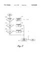
- FIG. 2is a flow diagram illustrating the manner in which the atrial defibrillator of FIG. 1 may be implemented in accordance with a preferred embodiment of the present invention.
- FIG. 1it illustrates a fully implantable atrial defibrillator 30 embodying the present invention shown in association with a schematically illustrated human heart 10 in need of atrial fibrillation monitoring and potential cardioversion of the atria.
- the portions of the heart 10 illustrated in FIG. 1are the right ventricle 12, the left ventricle 14, the right atrium 16, the left atrium 18, the superior vena cava 20, the coronary sinus channel 21 which, as used herein, denotes the coronary sinus 22 and the great cardiac vein 23', the coronary sinus ostium or opening 24, the left ventricular free wall 26 and the inferior vena cava 27.
- the term "ventricular activations”denotes R waves of the heart cardiac cycle which induce depolarizations of the ventricles 12 and 14.
- the atrial defibrillator 30generally includes an enclosure 32 for hermetically sealing the internal circuit elements of the atrial defibrillator to be described hereinafter, an endocardial first lead 34, and an intravascular second lead 36.
- the enclosure 32 and first and second leads 34 and 36are arranged to be implanted beneath the skin of a patient so as to render the atrial defibrillator 30 fully implantable.
- the endocardial first lead 34preferably comprises an endocardial bi-polar lead having electrodes 38 and 40 arranged for establishing electrical contact with the right ventricle 12 of the heart 10.
- the electrodes 38 and 40permit bi-polar sensing of ventricular activations in the right ventricle.
- the lead 34is preferably fed through the superior vena cava 20, into the right atrium 16, and then into the right ventricle 12 as illustrated.
- the second lead 36generally includes a first or tip electrode 44 and a second or proximal electrode 46.
- the second lead 36is flexible and arranged to be passed down the superior vena cava 20, into the right atrium 16, into the coronary sinus ostium 24, and advanced into the coronary sinus channel 21 of the heart near the left side thereof so that the first or tip electrode 44 is within the coronary sinus channel 21, either within the coronary sinus 22 adjacent the left ventricle 14 and beneath the left atrium 18, or most preferably within the great cardiac vein 23 adjacent the left ventricle 14 and beneath the left atrium 18.
- the electrodes 44 and 46are spaced apart such that when the first electrode 44 is positioned as described above, the second electrode 46 is in the right atrium 16.
- the first electrode 44 together with the second electrode 46provide bi-polar sensing of heart activity in the atria 16 and 18.
- the first electrode 44 and the second electrode 46further provide for the delivery of defibrillating electrical energy to the atria. Because the first electrode 44 is located beneath the left atrium 18 near the left ventricle 14 and the second electrode 46 is within the right atrium 16, the electrical energy applied between these electrodes will be substantially confined to the atria 16 and 18 of the heart 10.
- the atrial defibrillator 30includes a first sense amplifier 50, an R wave detector 52, and a second sense amplifier 54.
- the first sense amplifier 50 and the R wave detector 52form a first detecting means which, together with the first lead 34 to which sense amplifier 50 is coupled, senses ventricular activations of the right ventricle 12.
- the second sense amplifier 54forms a second detecting means which, together with the first electrode 44 and second electrode 46 of the second lead 36 to which it is coupled, detects atrial activity of the heart.
- the output of the first sense amplifier 50is coupled to the R wave detector 52.
- the R wave detector 52is of the type well known in the art which provides an output pulse upon the occurrence of an R wave being sensed during a cardiac cycle of the heart.
- the output of the second sense amplifier 54is coupled to an analog to digital converter 60 which converts the analog signal representative of the atrial activity of the heart being detected to digital samples for further processing in a manner to be described hereinafter.
- the enclosure 32 of the atrial defibrillator 30further includes a microprocessor 62.
- the microprocessor 62is preferably implemented in a manner as will be described hereinafter with respect to the flow diagram of FIG. 2 for providing automatic adaptive control of the output voltage of the defibrillator 30.
- the implementation of the microprocessor 62 in accordance with this embodiment of the present inventionresults in a plurality of functional stages.
- the stagesinclude a timer 64, an internal memory 66, a comparator stage 68, an atrial arrhythmia detector in the form of an atrial fibrillation detector 70, a charge delivery and energy control stage 72, a computation stage 80, a shock voltage increment stage 82, a shock voltage decrement stage 84, and a counter 86.
- the microprocessor 62is arranged to operate in conjunction with an external memory (not shown) which may be coupled to the microprocessor 62 by a multiple-bit address bus (not shown) and a bi-directional multiple-bit data bus (not shown). This permits the microprocessor 62 to address desired memory locations within the memory for executing write or read operations.
- the microprocessorstores data, such as time intervals, or operating parameters in the memory at the addresses defined by multiple-bit addresses conveyed over the address bus and conveys the data to the memory 92 over the multiple-bit data bus.
- the microprocessor 62obtains data from the memory at the storage locations identified by the multiple-bit addresses provided over the address bus and receives the data from the memory over the bi-directional data bus.
- the microprocessor 62receives the programmable operating parameters from an external controller 100 which is external to the skin of the patient.
- the external controller 100is arranged to communicate with a receiver/transmitter 102 which is coupled to the microprocessor 62 over a bi-directional bus 104.
- the receiver/transmitter 102may be of the type well known in the art for conveying various information which it obtains from the microprocessor 62 to the external controller 100 or for receiving programmable operating parameters from the external controller 100 which the receiver/transmitter 102 then conveys to the microprocessor 62 for storage in internal memory 66, a memory portion 67, or in the aforementioned external memory within enclosure 32.
- the receiver/transmitter 102includes a transmitting coil 106 so that the receiver/transmitter 102 and coil 106 form a communication means.
- Such communication meansare well known in the art and may be utilized as noted above for receiving commands from external to the implantable enclosures 32 and for transmitting data to the external controller 100 from the implanted enclosure 32.
- the atrial defibrillator 30further includes a charger and storage capacitor circuit 74 of the type well known in the art which charges a storage capacitor to a predetermined voltage level and a discharge circuit 76 for discharging the storage capacitor within circuit 74 for a predetermined discharge time to provide a controlled discharge output of electrical energy when required to the atria of the heart.
- the discharge circuit 76is coupled to the first electrode 44 and the second electrode 46 of the second lead 36 for applying the cardioverting or defibrillating electrical energy to the atria.
- the defibrillator 30includes a depletable power source such as a lithium battery, for providing power to the electrical components of the atrial defibrillator 30.
- the charge delivery control 72causes the charger and storage capacitor circuit 74 to charge the storage capacitor within circuit 74 to a desired voltage having a desired magnitude.
- the timer 64After the capacitor of circuit 74 is charged to the desired magnitude, the timer 64 times the time intervals between R waves of the heart. When timer 64 times a heart interval which is longer than the preselected minimum time interval, the charge delivery control 72 causes the discharge circuit 76 to discharge the capacitor of circuit 74 for a fixed period of time to apply the cardioverting electrical energy to electrodes 44 and 46 and thus the atria in timed relation to the R wave ending the last timed interval.
- the atrial fibrillation detector 70determines if the cardioversion attempt was successful. If the attempt was not successful and the atria are still in fibrillation, the counter 86 is incremented and the defibrillator repeats the therapy at the same voltage.
- step 110the counter 86 is interrogated to determine if it has counted a number of attempted cardioversions at the current voltage magnitude equal to or greater than some preset number such as ten, for example. This assures that further analysis will be based upon sufficient data to provide a statistically accurate result. If there have been less than N number of cardioversion attempts at the current voltage magnitude, the counter 86 is incremented at step 112 and the subroutine returns.
- the percentage of successful cardioversionis then computed by the computation stage 80. If, for example, five attempts were successful out of a total of ten attempts, the percentage of success at the current shock voltage would be fifty percent (50%).
- the compare stage 68determines if the percentage of success (S) at the current voltage is below a predetermined range having a lower limit of, for example, twenty-five percent (25%). If S is equal to or less than the lower limit, the shock voltage incrementing stage 82 incrementally increases the voltage output setting of the defibrillator at step 116. The capacitor of circuit 74, for the next attempt, will now be charged to an incrementally increased voltage before being discharged. This is to increase the percentage of success for this patient.
- the voltage incrementsmay be any desired increment, for example ten (10) volts.
- the counter 86is reset to zero in step 118.
- the compare stage 68next in step 120 determines if S is equal to or greater than an upper limit of, for example, seventy-five percent (75%). If it is, the shock voltage decrementing stage 84, in step 122, decrements the output voltage setting of the defibrillator 30 by an amount, such as ten (10) volts, to decrease the percentage of success. Now, for the next cardioversion attempt, the capacitor of circuit 74 will be charged to a voltage which is ten (10) volts less than the voltage used in the immediately preceding attempt.
- the output voltage of the defibrillatorwill be adaptively adjusted to maintain a percentage of success within a desired range. This will assure that the battery power of the implanted defibrillator is efficiently utilized and that the patient is not being subject to more voltage than reasonably necessary.
- Another feature of the present inventionis in the generation of data representing a true percent of success versus voltage relationship-
- Each percent of success calculated by the computation stage 80may be stored in memory 66 together with its corresponding output voltage. That data may then be transmitted to an external receiver, such as programmer 100, for use by the physician during patient follow-up.
- the percentage of success versus applied voltagemay be plotted on a curve tracer or otherwise displayed to permit the physician to select an applied voltage range defined by a minimum permitted applied voltage and a maximum permitted applied voltage.
- the applied voltage rangepreferably over rides any voltage selection based upon percentage of success versus voltage. This may be especially important if the percentage of success versus voltage changes over time.
- the minimum and maximum permitted applied voltagesmay be stored in a memory portion 67 dedicated to that function and the microprocessor may be programmed to prevent any output voltage increment or decrement which would cause the applied voltage to transition out of the physician prescribed range.
- the present inventionmay further find particular utility in a defibrillator which provides different output voltage levels during therapy intervention.
- the output voltage magnitudeis stored together with an indicia of success or failure and the total number of attempts at that voltage.
- the voltage levelsmay be adjusted or the sequence changed based upon percent of success to maximize a given factor.
- the above implementationhas a number of characteristics. First, it seeks a target percent success which is a function of I/(I+D). The peak cardioversion voltage hunts or oscillates around the target percent success. The amplitude of the oscillations is a function of the maximum (I,D) and the slope of the dose-response curve at the target percent success. Lastly, only one data parameter (Vsn) need be temporarily stored or otherwise maintained for each attempted cardioversion.
Landscapes
- Health & Medical Sciences (AREA)
- Cardiology (AREA)
- Heart & Thoracic Surgery (AREA)
- Engineering & Computer Science (AREA)
- Biomedical Technology (AREA)
- Nuclear Medicine, Radiotherapy & Molecular Imaging (AREA)
- Radiology & Medical Imaging (AREA)
- Life Sciences & Earth Sciences (AREA)
- Animal Behavior & Ethology (AREA)
- General Health & Medical Sciences (AREA)
- Public Health (AREA)
- Veterinary Medicine (AREA)
- Electrotherapy Devices (AREA)
Abstract
Description
Claims (21)
Priority Applications (1)
| Application Number | Priority Date | Filing Date | Title |
|---|---|---|---|
| US08/641,100US5674250A (en) | 1996-04-29 | 1996-04-29 | Atrial defibrillator and method for providing adaptive control of defibrillator output voltage |
Applications Claiming Priority (1)
| Application Number | Priority Date | Filing Date | Title |
|---|---|---|---|
| US08/641,100US5674250A (en) | 1996-04-29 | 1996-04-29 | Atrial defibrillator and method for providing adaptive control of defibrillator output voltage |
Publications (1)
| Publication Number | Publication Date |
|---|---|
| US5674250Atrue US5674250A (en) | 1997-10-07 |
Family
ID=24570935
Family Applications (1)
| Application Number | Title | Priority Date | Filing Date |
|---|---|---|---|
| US08/641,100Expired - Fee RelatedUS5674250A (en) | 1996-04-29 | 1996-04-29 | Atrial defibrillator and method for providing adaptive control of defibrillator output voltage |
Country Status (1)
| Country | Link |
|---|---|
| US (1) | US5674250A (en) |
Cited By (28)
| Publication number | Priority date | Publication date | Assignee | Title |
|---|---|---|---|---|
| US6430438B1 (en) | 1999-05-21 | 2002-08-06 | Cardiac Pacemakers, Inc. | Cardiac rhythm management system with atrial shock timing optimization |
| US6512951B1 (en) | 2000-09-14 | 2003-01-28 | Cardiac Pacemakers, Inc. | Delivery of atrial defibrillation shock based on estimated QT interval |
| US20030069610A1 (en)* | 1999-05-21 | 2003-04-10 | Cardiac Pacemakers, Inc. | Apparatus and method for ventricular rate regularization with biventricular sensing |
| US6584350B2 (en) | 2001-04-06 | 2003-06-24 | Cardiac Pacemakers, Inc. | Apparatus and method for R-wave detection with dual dynamic sensitivities |
| US20030199928A1 (en)* | 1998-03-19 | 2003-10-23 | Cardiac Pacemakers, Inc. | System for treating supraventricular tachyarrhythmias |
| US6704597B1 (en) | 2000-07-20 | 2004-03-09 | Cardiac Pacemakers, Inc. | Apparatus and method for energy management in atrial defibrillator |
| US6721596B1 (en) | 2000-05-15 | 2004-04-13 | Cardiac Pacemakers, Inc. | Atrial shock therapy with ventricular pacing |
| US6763267B2 (en) | 2000-07-13 | 2004-07-13 | Cardiac Pacemakers, Inc. | Ventricular conduction delay trending system and method |
| EP1304138A3 (en)* | 2001-10-17 | 2004-08-18 | Pacesetter, Inc. | Automatic defibrillation shock energy adjuster |
| US20040260347A1 (en)* | 2001-04-05 | 2004-12-23 | Cardiac Pacemakers, Inc. | Cardiac rhythm management system synchronizing atrial shock to ventricular depolarization based on sensing refractory |
| US6847842B1 (en) | 2000-05-15 | 2005-01-25 | Cardiac Pacemakers, Inc. | Method and apparatus for reducing early recurrence of atrial fibrillation with defibrillation shock therapy |
| US6957100B2 (en) | 2000-12-26 | 2005-10-18 | Cardiac Pacemakers, Inc. | Method and system for display of cardiac event intervals in a resynchronization pacemaker |
| US7039461B1 (en) | 2000-05-13 | 2006-05-02 | Cardiac Pacemakers, Inc. | Cardiac pacing system for prevention of ventricular fibrillation and ventricular tachycardia episode |
| US7062325B1 (en) | 1999-05-21 | 2006-06-13 | Cardiac Pacemakers Inc | Method and apparatus for treating irregular ventricular contractions such as during atrial arrhythmia |
| US7069077B2 (en) | 2000-05-26 | 2006-06-27 | Cardiac Pacemakers, Inc. | Rate smoothing control |
| US7113824B2 (en) | 1997-04-30 | 2006-09-26 | Cardiac Pacemakers, Inc. | Apparatus and method for treating ventricular tachyarrhythmias |
| US7142915B2 (en) | 2000-12-29 | 2006-11-28 | Cardiac Pacemakers, Inc. | Apparatus and method for ventricular rate regularization |
| US7181278B2 (en) | 1999-05-21 | 2007-02-20 | Cardiac Pacemakers, Inc. | Apparatus and method for ventricular rate regularization |
| US7212860B2 (en) | 1999-05-21 | 2007-05-01 | Cardiac Pacemakers, Inc. | Apparatus and method for pacing mode switching during atrial tachyarrhythmias |
| US7239914B2 (en) | 2000-05-13 | 2007-07-03 | Cardiac Pacemakers, Inc. | Rate smoothing control |
| US7981065B2 (en) | 2004-12-20 | 2011-07-19 | Cardiac Pacemakers, Inc. | Lead electrode incorporating extracellular matrix |
| US8064997B2 (en) | 1999-05-21 | 2011-11-22 | Cardiac Pacemakers, Inc. | Method and apparatus for treating irregular ventricular contractions such as during atrial arrhythmia |
| US8512220B2 (en) | 2000-05-26 | 2013-08-20 | Cardiac Pacemakers, Inc. | Rate smoothing control |
| US8874204B2 (en) | 2004-12-20 | 2014-10-28 | Cardiac Pacemakers, Inc. | Implantable medical devices comprising isolated extracellular matrix |
| US10350419B2 (en) | 2007-12-13 | 2019-07-16 | Cardiac Pacemakers, Inc. | Supraventricular tachy sensing vector |
| US10953234B2 (en) | 2015-08-26 | 2021-03-23 | Element Science, Inc. | Wearable devices |
| US11185709B2 (en) | 2014-02-24 | 2021-11-30 | Element Science, Inc. | External defibrillator |
| US11253715B2 (en) | 2018-10-10 | 2022-02-22 | Element Science, Inc. | Wearable medical device with disposable and reusable components |
Citations (3)
| Publication number | Priority date | Publication date | Assignee | Title |
|---|---|---|---|---|
| US5395373A (en)* | 1993-01-07 | 1995-03-07 | Incontrol, Inc. | Atrial defibrillator and method for setting energy threshold values |
| US5507780A (en)* | 1995-01-25 | 1996-04-16 | Finch; David P. | Selective default data storage for an implantable atrial defibrillator |
| US5531770A (en)* | 1993-09-03 | 1996-07-02 | Angeion Corporation | Device and method for determining defibrillation thresholds |
- 1996
- 1996-04-29USUS08/641,100patent/US5674250A/ennot_activeExpired - Fee Related
Patent Citations (3)
| Publication number | Priority date | Publication date | Assignee | Title |
|---|---|---|---|---|
| US5395373A (en)* | 1993-01-07 | 1995-03-07 | Incontrol, Inc. | Atrial defibrillator and method for setting energy threshold values |
| US5531770A (en)* | 1993-09-03 | 1996-07-02 | Angeion Corporation | Device and method for determining defibrillation thresholds |
| US5507780A (en)* | 1995-01-25 | 1996-04-16 | Finch; David P. | Selective default data storage for an implantable atrial defibrillator |
Cited By (59)
| Publication number | Priority date | Publication date | Assignee | Title |
|---|---|---|---|---|
| US8306619B2 (en) | 1997-04-30 | 2012-11-06 | Cardiac Pacemakers, Inc. | Apparatus and method for treating ventricular tachyarrhythmias |
| US7522956B2 (en) | 1997-04-30 | 2009-04-21 | Cardiac Pacemakers, Inc. | Apparatus and method for treating ventricular tachyarrhythmias |
| US8046068B2 (en) | 1997-04-30 | 2011-10-25 | Cardiac Pacemakers, Inc. | Apparatus and method for treating ventricular tachyarrhythmias |
| US7113824B2 (en) | 1997-04-30 | 2006-09-26 | Cardiac Pacemakers, Inc. | Apparatus and method for treating ventricular tachyarrhythmias |
| US20030199928A1 (en)* | 1998-03-19 | 2003-10-23 | Cardiac Pacemakers, Inc. | System for treating supraventricular tachyarrhythmias |
| US6873873B2 (en) | 1998-03-19 | 2005-03-29 | Cardiac Pacemakers, Inc. | System for treating supraventricular tachyarrhythmias |
| US7460908B2 (en) | 1999-05-21 | 2008-12-02 | Cardiac Pacemakers, Inc. | System providing ventricular pacing and biventricular coordination |
| US7212860B2 (en) | 1999-05-21 | 2007-05-01 | Cardiac Pacemakers, Inc. | Apparatus and method for pacing mode switching during atrial tachyarrhythmias |
| US7062325B1 (en) | 1999-05-21 | 2006-06-13 | Cardiac Pacemakers Inc | Method and apparatus for treating irregular ventricular contractions such as during atrial arrhythmia |
| US7120490B2 (en) | 1999-05-21 | 2006-10-10 | Cardiac Pacemakers, Inc. | Cardiac rhythm management system with atrial shock timing optimization |
| US8135465B2 (en) | 1999-05-21 | 2012-03-13 | Cardiac Pacemakers, Inc. | System providing ventricular pacing and biventricular coordination |
| US8064997B2 (en) | 1999-05-21 | 2011-11-22 | Cardiac Pacemakers, Inc. | Method and apparatus for treating irregular ventricular contractions such as during atrial arrhythmia |
| US8391974B2 (en) | 1999-05-21 | 2013-03-05 | Cardiac Pacemakers, Inc. | Apparatus and method for pacing mode switching during atrial tachyarrhythmias |
| US6430438B1 (en) | 1999-05-21 | 2002-08-06 | Cardiac Pacemakers, Inc. | Cardiac rhythm management system with atrial shock timing optimization |
| US8249703B2 (en) | 1999-05-21 | 2012-08-21 | Cardiac Pacemakers, Inc. | Apparatus and method for ventricular rate regularization |
| US20030069610A1 (en)* | 1999-05-21 | 2003-04-10 | Cardiac Pacemakers, Inc. | Apparatus and method for ventricular rate regularization with biventricular sensing |
| US7856267B2 (en) | 1999-05-21 | 2010-12-21 | Cardiac Pacemakers, Inc. | Apparatus and method for pacing mode switching during atrial tachyarrhythmias |
| US6988002B2 (en) | 1999-05-21 | 2006-01-17 | Cardiac Pacemakers, Inc. | Apparatus and method for ventricular rate regularization with biventricular sensing |
| US7181278B2 (en) | 1999-05-21 | 2007-02-20 | Cardiac Pacemakers, Inc. | Apparatus and method for ventricular rate regularization |
| US8239021B2 (en) | 2000-05-13 | 2012-08-07 | Cardiac Pacemakers, Inc. | Cardiac pacing system for prevention of ventricular fibrillation and ventricular tachycardia episode |
| US7742814B2 (en) | 2000-05-13 | 2010-06-22 | Cardiac Pacemakers, Inc. | Cardiac pacing system for prevention of ventricular fibrillation and ventricular tachycardia episode |
| US7039461B1 (en) | 2000-05-13 | 2006-05-02 | Cardiac Pacemakers, Inc. | Cardiac pacing system for prevention of ventricular fibrillation and ventricular tachycardia episode |
| US7239914B2 (en) | 2000-05-13 | 2007-07-03 | Cardiac Pacemakers, Inc. | Rate smoothing control |
| US6847842B1 (en) | 2000-05-15 | 2005-01-25 | Cardiac Pacemakers, Inc. | Method and apparatus for reducing early recurrence of atrial fibrillation with defibrillation shock therapy |
| US6721596B1 (en) | 2000-05-15 | 2004-04-13 | Cardiac Pacemakers, Inc. | Atrial shock therapy with ventricular pacing |
| US7069077B2 (en) | 2000-05-26 | 2006-06-27 | Cardiac Pacemakers, Inc. | Rate smoothing control |
| US8512220B2 (en) | 2000-05-26 | 2013-08-20 | Cardiac Pacemakers, Inc. | Rate smoothing control |
| US6763267B2 (en) | 2000-07-13 | 2004-07-13 | Cardiac Pacemakers, Inc. | Ventricular conduction delay trending system and method |
| US7383086B2 (en) | 2000-07-13 | 2008-06-03 | Cardiac Pacemakers, Inc. | Ventricular conduction delay trending system and method |
| US20050027318A1 (en)* | 2000-07-20 | 2005-02-03 | Cardiac Pacemakers, Inc. | Apparatus and method for energy management in atrial defibrillator |
| US7203539B2 (en) | 2000-07-20 | 2007-04-10 | Cardiac Pacemakers, Inc. | Apparatus and method for energy management in atrial defibrillator |
| US6704597B1 (en) | 2000-07-20 | 2004-03-09 | Cardiac Pacemakers, Inc. | Apparatus and method for energy management in atrial defibrillator |
| US6512951B1 (en) | 2000-09-14 | 2003-01-28 | Cardiac Pacemakers, Inc. | Delivery of atrial defibrillation shock based on estimated QT interval |
| US6687541B2 (en) | 2000-09-14 | 2004-02-03 | Cardiac Pacemakers, Inc. | Method for delivering atrial defibrillation therapy |
| US6957100B2 (en) | 2000-12-26 | 2005-10-18 | Cardiac Pacemakers, Inc. | Method and system for display of cardiac event intervals in a resynchronization pacemaker |
| US7680530B2 (en) | 2000-12-26 | 2010-03-16 | Cardiac Pacemakers, Inc. | Method and system for display of cardiac event intervals in a resynchronization pacemaker |
| US7047066B2 (en) | 2000-12-26 | 2006-05-16 | Cardiac Pacemakers, Inc. | Method and system for display of cardiac event intervals in a resynchronization pacemaker |
| US8103334B2 (en) | 2000-12-26 | 2012-01-24 | Cardiac Pacemakers, Inc. | Method and system for display of cardiac event intervals in a resynchronization pacemaker |
| US7142915B2 (en) | 2000-12-29 | 2006-11-28 | Cardiac Pacemakers, Inc. | Apparatus and method for ventricular rate regularization |
| US6963776B2 (en) | 2001-04-05 | 2005-11-08 | Cardiac Pacemakers, Inc. | Cardiac rhythm management system synchronizing atrial shock to ventricular depolarization based on length of sensing refractory |
| US7133720B2 (en) | 2001-04-05 | 2006-11-07 | Cardiac Pacemakers, Inc. | Cardiac rhythm management system synchronizing atrial shock to ventricular depolarization based on length of sensing refractory |
| US20040260347A1 (en)* | 2001-04-05 | 2004-12-23 | Cardiac Pacemakers, Inc. | Cardiac rhythm management system synchronizing atrial shock to ventricular depolarization based on sensing refractory |
| US7209785B2 (en) | 2001-04-06 | 2007-04-24 | Cardiac Pacemakers, Inc. | Apparatus and method for R-wave detection with dual dynamic sensitivities |
| US20040015192A1 (en)* | 2001-04-06 | 2004-01-22 | Cardiac Pacemakers, Inc. | Apparatus and method for R-wave detection with dual dynamic sensitivities |
| US6584350B2 (en) | 2001-04-06 | 2003-06-24 | Cardiac Pacemakers, Inc. | Apparatus and method for R-wave detection with dual dynamic sensitivities |
| EP1304138A3 (en)* | 2001-10-17 | 2004-08-18 | Pacesetter, Inc. | Automatic defibrillation shock energy adjuster |
| US7076295B1 (en)* | 2001-10-17 | 2006-07-11 | Pacesetter, Inc. | Automatic defibrillation shock energy adjuster |
| US8874204B2 (en) | 2004-12-20 | 2014-10-28 | Cardiac Pacemakers, Inc. | Implantable medical devices comprising isolated extracellular matrix |
| US7981065B2 (en) | 2004-12-20 | 2011-07-19 | Cardiac Pacemakers, Inc. | Lead electrode incorporating extracellular matrix |
| US10350419B2 (en) | 2007-12-13 | 2019-07-16 | Cardiac Pacemakers, Inc. | Supraventricular tachy sensing vector |
| US11504538B2 (en) | 2007-12-13 | 2022-11-22 | Cardiac Pacemakers, Inc. | Supraventricular tachy sensing vector |
| US11185709B2 (en) | 2014-02-24 | 2021-11-30 | Element Science, Inc. | External defibrillator |
| US11975209B2 (en) | 2014-02-24 | 2024-05-07 | Element Science, Inc. | External defibrillator |
| US12427329B2 (en) | 2014-02-24 | 2025-09-30 | Element Science, Inc. | External defibrillator |
| US10953234B2 (en) | 2015-08-26 | 2021-03-23 | Element Science, Inc. | Wearable devices |
| US11701521B2 (en) | 2015-08-26 | 2023-07-18 | Element Science, Inc. | Wearable devices |
| US12350508B2 (en) | 2015-08-26 | 2025-07-08 | Element Science, Inc. | Wearable devices |
| US11253715B2 (en) | 2018-10-10 | 2022-02-22 | Element Science, Inc. | Wearable medical device with disposable and reusable components |
| US12186573B2 (en) | 2018-10-10 | 2025-01-07 | Element Science, Inc. | Wearable medical device with disposable and reusable components |
Similar Documents
| Publication | Publication Date | Title |
|---|---|---|
| US5674250A (en) | Atrial defibrillator and method for providing adaptive control of defibrillator output voltage | |
| CA2112772C (en) | Atrial defibrillator and method for setting energy threshold values | |
| US5265600A (en) | Atrial defibrillator and method for providing post-cardioversion pacing | |
| US5282836A (en) | Atrial defibrillator and method for providing pre-cardioversion pacing | |
| US5486198A (en) | Atrial defibrillator and method for providing interval timing of successive intervals prior to cardioversion | |
| US5269298A (en) | Atrial defibrillator and method for providing synchronized delayed cardioversion | |
| AU657247B2 (en) | Atrial defibrillator and method for providing interval timing prior to cardioversion | |
| US5332400A (en) | Atrial defibrillator and method for providing pre-cardioversion warning | |
| US5549641A (en) | Atrial fibrillation type selective cardiovertor and method | |
| EP0693301B1 (en) | System for reducing false positives in atrial fibrillation detection | |
| US5814081A (en) | Atrial flutter cardioverter and method | |
| CA2145592C (en) | An implantable atrial defibrillator having an intermittently activated pacing modality | |
| EP0627240B1 (en) | Atrial defibrillator for providing T wave detection and interval timing prior to cardioversion | |
| AU758606B2 (en) | System and method for detecting atrial events of a heart using only atrial sensing | |
| US6249699B1 (en) | Cardioverter and method for cardioverting an atrial tachyarrhythmia in the presence of atrial pacing | |
| US5267559A (en) | Atrial defibrillator and method for providing atrial sensing | |
| EP0770410B1 (en) | An implantable atrial defibrillator having cardioverting output voltage limiting for simulating larger storage capacitors | |
| US5813999A (en) | Implantable atrial defibrillator providing reduced cardioversion discomfort | |
| US5653740A (en) | Method and apparatus for induction of fibrillation |
Legal Events
| Date | Code | Title | Description |
|---|---|---|---|
| AS | Assignment | Owner name:INCONTROL INC., WASHINGTON Free format text:ASSIGNMENT OF ASSIGNORS INTEREST;ASSIGNORS:DE CORIOLIS, PAUL E.;AYERS, GREGORY M.;REEL/FRAME:007988/0015 Effective date:19960429 | |
| CC | Certificate of correction | ||
| AS | Assignment | Owner name:CARDIAC PACEMAKERS, INC., MINNESOTA Free format text:ASSIGNMENT OF ASSIGNORS INTEREST;ASSIGNOR:INCONTROL, INC.;REEL/FRAME:009781/0901 Effective date:19990202 | |
| FEPP | Fee payment procedure | Free format text:PAT HLDR NO LONGER CLAIMS SMALL ENT STAT AS SMALL BUSINESS (ORIGINAL EVENT CODE: LSM2); ENTITY STATUS OF PATENT OWNER: LARGE ENTITY | |
| REFU | Refund | Free format text:REFUND - PAYMENT OF MAINTENANCE FEE, 4TH YR, SMALL ENTITY (ORIGINAL EVENT CODE: R283); ENTITY STATUS OF PATENT OWNER: LARGE ENTITY | |
| FPAY | Fee payment | Year of fee payment:4 | |
| FPAY | Fee payment | Year of fee payment:8 | |
| REMI | Maintenance fee reminder mailed | ||
| LAPS | Lapse for failure to pay maintenance fees | ||
| STCH | Information on status: patent discontinuation | Free format text:PATENT EXPIRED DUE TO NONPAYMENT OF MAINTENANCE FEES UNDER 37 CFR 1.362 | |
| FP | Lapsed due to failure to pay maintenance fee | Effective date:20091007 |