US5674026A - Shaft coupling structure of drive shaft - Google Patents
Shaft coupling structure of drive shaftDownload PDFInfo
- Publication number
- US5674026A US5674026AUS08/391,682US39168295AUS5674026AUS 5674026 AUS5674026 AUS 5674026AUS 39168295 AUS39168295 AUS 39168295AUS 5674026 AUS5674026 AUS 5674026A
- Authority
- US
- United States
- Prior art keywords
- shaft
- male
- female
- coupling structure
- shafts
- Prior art date
- Legal status (The legal status is an assumption and is not a legal conclusion. Google has not performed a legal analysis and makes no representation as to the accuracy of the status listed.)
- Expired - Fee Related
Links
Images


Classifications
- F—MECHANICAL ENGINEERING; LIGHTING; HEATING; WEAPONS; BLASTING
- F16—ENGINEERING ELEMENTS AND UNITS; GENERAL MEASURES FOR PRODUCING AND MAINTAINING EFFECTIVE FUNCTIONING OF MACHINES OR INSTALLATIONS; THERMAL INSULATION IN GENERAL
- F16C—SHAFTS; FLEXIBLE SHAFTS; ELEMENTS OR CRANKSHAFT MECHANISMS; ROTARY BODIES OTHER THAN GEARING ELEMENTS; BEARINGS
- F16C3/00—Shafts; Axles; Cranks; Eccentrics
- F16C3/02—Shafts; Axles
- F16C3/03—Shafts; Axles telescopic
- F16C3/035—Shafts; Axles telescopic with built-in bearings
- F—MECHANICAL ENGINEERING; LIGHTING; HEATING; WEAPONS; BLASTING
- F16—ENGINEERING ELEMENTS AND UNITS; GENERAL MEASURES FOR PRODUCING AND MAINTAINING EFFECTIVE FUNCTIONING OF MACHINES OR INSTALLATIONS; THERMAL INSULATION IN GENERAL
- F16D—COUPLINGS FOR TRANSMITTING ROTATION; CLUTCHES; BRAKES
- F16D1/00—Couplings for rigidly connecting two coaxial shafts or other movable machine elements
- F16D1/06—Couplings for rigidly connecting two coaxial shafts or other movable machine elements for attachment of a member on a shaft or on a shaft-end
- F16D1/08—Couplings for rigidly connecting two coaxial shafts or other movable machine elements for attachment of a member on a shaft or on a shaft-end with clamping hub; with hub and longitudinal key
- F16D1/0876—Couplings for rigidly connecting two coaxial shafts or other movable machine elements for attachment of a member on a shaft or on a shaft-end with clamping hub; with hub and longitudinal key with axial keys and no other radial clamping
- F—MECHANICAL ENGINEERING; LIGHTING; HEATING; WEAPONS; BLASTING
- F16—ENGINEERING ELEMENTS AND UNITS; GENERAL MEASURES FOR PRODUCING AND MAINTAINING EFFECTIVE FUNCTIONING OF MACHINES OR INSTALLATIONS; THERMAL INSULATION IN GENERAL
- F16D—COUPLINGS FOR TRANSMITTING ROTATION; CLUTCHES; BRAKES
- F16D3/00—Yielding couplings, i.e. with means permitting movement between the connected parts during the drive
- F16D3/02—Yielding couplings, i.e. with means permitting movement between the connected parts during the drive adapted to specific functions
- F16D3/06—Yielding couplings, i.e. with means permitting movement between the connected parts during the drive adapted to specific functions specially adapted to allow axial displacement
- F—MECHANICAL ENGINEERING; LIGHTING; HEATING; WEAPONS; BLASTING
- F16—ENGINEERING ELEMENTS AND UNITS; GENERAL MEASURES FOR PRODUCING AND MAINTAINING EFFECTIVE FUNCTIONING OF MACHINES OR INSTALLATIONS; THERMAL INSULATION IN GENERAL
- F16D—COUPLINGS FOR TRANSMITTING ROTATION; CLUTCHES; BRAKES
- F16D1/00—Couplings for rigidly connecting two coaxial shafts or other movable machine elements
- F16D1/10—Quick-acting couplings in which the parts are connected by simply bringing them together axially
- F16D2001/103—Quick-acting couplings in which the parts are connected by simply bringing them together axially the torque is transmitted via splined connections
- F—MECHANICAL ENGINEERING; LIGHTING; HEATING; WEAPONS; BLASTING
- F16—ENGINEERING ELEMENTS AND UNITS; GENERAL MEASURES FOR PRODUCING AND MAINTAINING EFFECTIVE FUNCTIONING OF MACHINES OR INSTALLATIONS; THERMAL INSULATION IN GENERAL
- F16D—COUPLINGS FOR TRANSMITTING ROTATION; CLUTCHES; BRAKES
- F16D2300/00—Special features for couplings or clutches
- F16D2300/22—Vibration damping
- Y—GENERAL TAGGING OF NEW TECHNOLOGICAL DEVELOPMENTS; GENERAL TAGGING OF CROSS-SECTIONAL TECHNOLOGIES SPANNING OVER SEVERAL SECTIONS OF THE IPC; TECHNICAL SUBJECTS COVERED BY FORMER USPC CROSS-REFERENCE ART COLLECTIONS [XRACs] AND DIGESTS
- Y10—TECHNICAL SUBJECTS COVERED BY FORMER USPC
- Y10T—TECHNICAL SUBJECTS COVERED BY FORMER US CLASSIFICATION
- Y10T403/00—Joints and connections
- Y10T403/70—Interfitted members
- Y10T403/7018—Interfitted members including separably interposed key
- Y10T403/7021—Axially extending
- Y10T403/7022—Resilient
- Y—GENERAL TAGGING OF NEW TECHNOLOGICAL DEVELOPMENTS; GENERAL TAGGING OF CROSS-SECTIONAL TECHNOLOGIES SPANNING OVER SEVERAL SECTIONS OF THE IPC; TECHNICAL SUBJECTS COVERED BY FORMER USPC CROSS-REFERENCE ART COLLECTIONS [XRACs] AND DIGESTS
- Y10—TECHNICAL SUBJECTS COVERED BY FORMER USPC
- Y10T—TECHNICAL SUBJECTS COVERED BY FORMER US CLASSIFICATION
- Y10T403/00—Joints and connections
- Y10T403/70—Interfitted members
- Y10T403/7026—Longitudinally splined or fluted rod
- Y10T403/7033—Longitudinally splined or fluted rod including a lock or retainer
Definitions
- the present inventionrelates in general to shaft coupling structures, and more particularly to shaft coupling structures of a drive shaft or the like. More specifically, the present invention is concerned with the shaft coupling structures of a type that comprises an internally splined tubular member and an externally splined shaft member coupled in a spline-connection manner.
- FRfront engine rear drive
- a drive shaftthat transmits power from an engine (specifically, a transmission connected thereto) mounted on a front portion of the vehicle to the differential for the rear road wheels connected to a rear portion of the vehicle through suspension devices.
- an enginespecifically, a transmission connected thereto
- two (front and rear) universal jointsare usually used.
- the front jointconnects the front end of the drive shaft to an output shaft of the transmission and the rear joint connects the rear end of the drive shaft to an input shaft of the differential. That is, the two universal joints serve to compensate for changes in angularity of a drive line from the transmission to the differential.
- Some of the drive shaftsare of a split type that comprises two parts coupled in a spline-connection manner to compensate for changes in the entire length of the drive line during movement of the vehicle.
- drive shafts of the split typetend to produce play between the two parts due to the inherent construction thereof.
- the playtends to cause generation of marked noise when receiving pulsating torque from the engine and/or vibration from the vehicle body.
- a shaft coupling structure of a drive shaft or the likewhich is free of the above-mentioned play and easy to assemble.
- a shaft coupling structurethat comprises an internally splined female shaft; an externally splined male shaft, the male shaft being coaxially received in the female shaft to establish a spline-connection therebetween; a play suppression member interposed between the male and female shafts for suppressing play of the male shaft relative to the female shaft and vice versa.
- the play suppression memberincludes an elongate member extending in and along an axially extending groove defined between the male and female shafts; a hook portion possessed by the elongate member, the hook portion being detachably fixed to one of the male and female shafts; and biasing means possessed by the elongate portion, the biasing means biasing the male and female shafts in radially opposite directions.
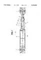
- FIG. 1is a partially cut sectional view of a drive shaft assembly having a shaft coupling structure of a first embodiment of the invention incorporated therein;
- FIG. 2is an enlarged view of a portion of the drive shaft assembly, which is indicated by the arrow "II" in FIG. 1;
- FIG. 3is a sectional view taken along the line III--III of FIG. 2;
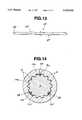
- FIG. 4is a sectional view taken along the line IV--IV of FIG. 2;
- FIG. 5is a partially cut side view of a front end portion of a spline shaft (or splined male shaft) constituting a part of the shaft coupling structure of the first embodiment;
- FIG. 6is a schematic view of the shaft coupling structure of the first embodiment, showing its feature exaggeratedly;
- FIG. 7is a view similar to FIG. 5, but showing another spline shaft (or splined male shaft) which constitutes a part of a shaft coupling structure of a second embodiment of the present invention
- FIG. 8is a view similar to FIG. 6 but showing the shaft coupling structure of the second embodiment exaggeratedly;
- FIG. 9is a view similar to FIG. 2, but showing a shaft coupling structure of a third embodiment of the present invention.
- FIG. 10is a sectional view taken along the line X--X of FIG. 9;
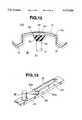
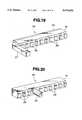
- FIGS. 11, 12 and 13are side, front and plan views of a play suppression bar employable in the third embodiment
- FIG. 14is a view similar to FIG. 4, but showing a shaft coupling structure of a fourth embodiment of the present invention.
- FIG. 15is an enlarged view of a part of the shaft coupling structure of FIG. 14;
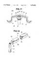
- FIG. 16is a perspective view of a play suppression bar employed in the fourth embodiment.
- FIG. 17is a view similar to FIG. 15, but showing a shaft coupling structure of a fifth embodiment of the present invention.
- FIG. 18is a perspective view of a play and suppression bar employed in the fifth embodiment.
- FIGS. 19 and 20are perspective views of other play suppression bars that can be used in the present invention.
- FIGS. 1 to 6 particularly FIG. 1there is shown a drive shaft assembly 10 having a shaft coupling structure of a first embodiment of the present invention incorporated therein.
- the drive shaft assembly 10comprises a drive shaft 12, a front universal joint 11 connected to a front end of the drive shaft 12, and a rear universal joint 17 connected to a rear end of the drive shaft 12.
- the front universal joint 11is connected to an output shaft of a transmission and the rear universal joint 17 is connected to an input shaft of a differential.
- the drive shaft 12comprises a first cylindrical part (14a+14b) and a second cylindrical part 16 coupled in a spline-connection manner as will become apparent as the description proceeds.
- the first cylindrical part (14a+14b)comprises a smaller diameter tubular portion 14a and a larger diameter tubular portion 14b coaxially connected to constitute an elongate stepped tubular structure, as shown.
- the bore of the smaller diameter tubular portion 14ais formed with a plurality of splines 13.
- the second cylindrical part 16is formed about its outer surface with a plurality of splines 15.
- the second cylindrical part 16is received in the bore of the smaller diameter tubular portion 14a of the first cylindrical part (14a+14b) while effecting a spline-connection therebetween.
- the two parts 16 and (14a+14b)can rotate together like a unit about their common axis while permitting a relative displacement therebetween in the direction of the common axis.
- the internally splined smaller diameter tubular portion 14a of the first cylindrical part (14a+14b)will be named as “female shaft”
- the externally splined second cylindrical part 16will be named as “male shaft” in the following.
- a so-called “play suppression bar” 18is put in a thin annular space defined between the male shaft 16 and the female shaft 14a of the first cylindrical part (14a and 14b).
- the spaceis filled with grease.
- a resilient steel wireis used as the play suppression bar 18.
- the elongate play suppression bar 18extends in and along one of longitudinally extending grooves 15a of the male shaft 16, each groove 15a being defined between adjacent two splines 15.
- the play suppression bar 18extends throughout the entire length of the groove 15a.
- the female shaft 14ahas at a diametrically opposed position another wider groove 13a" for the reason which will become apparent hereinafter.
- the front end of the play suppression bar 18is bent radially inward at right angles to form a hook portion 20 thrust into an engaging hole 19 formed in the bottom land of the male shaft 16.
- the bar 18is kept held by the male shaft 16 even when the relative displacement takes place between the male shaft 16 and the female shaft 14a.
- the play suppression bar 18is formed with two outwardly raised portions 21 each being resiliently pressed against the bottom land of the wider groove 13a' of the female shaft 14a.
- each raised portion 21 of the play suppression bar 18extends beyond the top of the adjacent spline 15 of the male shaft 16.
- the thickness of the play suppression bar 18can be increased to a degree corresponding to the height of the removed spline of the female shaft 14a, durability of the play suppression bar 18 is assured.
- the play suppression bar 18As a material of the play suppression bar 18, plastics and compound plastics are usable so long as they have sufficient resiliency and wear resistance. Although, in the above-mentioned embodiment, the play suppression bar 18 has two raised positions 21, the number of the raised portions 21 is not limited to two. That is, the bar 18 may have only one raised portion or more than two raised portions so long as they can produce a biasing force suitable for suppressing the play.
- two play suppression bars 22 and 23are employed, which are respectively accommodated in diametrically opposed grooves 15a and 15a' of the male shaft 16, each groove 15a or 15a' being defined between adjacent two splines 15.
- diametrically opposed two of the splines 13 of the female shaft 14a of the first cylindrical part (14a+14b), which would be engaged with the selected grooves 15a and 15a',have been removed, as will be understood from FIG. 4.
- the female shaft 14ahas two wider grooves 13a' and 13a", as shown.
- each bar 22 or 23is bent radially inward at right angles and thrust into an engaging hole 19 formed in the male shaft 16.
- the play suppression bar 22is formed at its front part with a raised portion 24a and the other play suppression bar 23 is formed at its rear part with a raised portion 24b.
- raised portions 24a and 24b of the bars 22 and 23are resiliently pressed against the bottom lands of the diametrically opposed wider grooves 13a' and 13a" of the female shaft 14a and thus the male shaft 16 is biased relative to the female shaft 14a and vice versa. Because the raised portions 24a and 24b are arranged in different positions in the axial direction, the compression of the raised portions 24a and 24b biases the male shaft 16 to pivot in the direction of the arrow "B" about the point "P", as is seen from FIG. 7. That is, in FIG.
- the male shaft 16is biased in a counterclockwise direction about the point "P" while the female shaft 14a is biased in a clockwise direction about the point "P", which biasing functions to bias these two shafts 16 and 14a to constitute a fixed bent structure and thus suppresses or at least minimizes the play of the male shaft 16 relative to the female shaft 14a and vice versa.
- Usage of the two play suppression bars 22 and 23 in this second embodimentinduces a balanced arrangement between the male and female shafts 16 and 14a.
- the shaft coupling structure of this third embodimentis substantially the same as that of the above-mentioned first embodiment except the following.
- the play suppression bar 25is held by or hooked to the female shaft 14a of the first cylindrical part (14a+14b).
- the front end of the bar 25is bent radially outward at right angles to form a hook portion 20 thrust into an engaging hole 26 formed in the female shaft 14a.
- the play suppression bar 25is formed with two inwardly raised portions 27, each being resiliently pressed against the bottom land of the groove 15a of the male shaft 16. That is, when the play suppression bar 25 is set in the right position, the two raised portions 27 of the bar 25 are compressed to produce a biasing force by which the two shafts 14a and 16 are biased in the opposite directions. Thus, undesired play of them is suppressed or at least minimized.
- FIGS. 11, 12 and 13there is shown a play suppression bar 25' that can be used as a substitute for the bar 25 of the third embodiment. That is, as is seen from FIG. 12, the two inwardly raised portions 27' of the play suppression bar 25' are inclined in a lateral direction to define therebetween a certain angle "2 ⁇ ". That is, in FIG. 12, one raised portion 27' is inclined leftward by " ⁇ " from a vertical plane "P” and the other raised portion 27' is inclined rightward by " ⁇ " from the vertical plane "P".
- the two raised portions 27'can have an apparent width "W" sufficient to make a pressed contact of the portions 27' with opposed side walls of the groove 15a of the male shaft 16.
- the pulsating torque from the enginecan be effectively absorbed by the shaft coupling structure.
- FIGS. 14, 15 and 16, particularly FIG. 14,there is shown a shaft coupling structure of a fourth embodiment of the present invention.
- three play suppression bars 28are employed, which are accommodated in three equally spaced grooves 15a, 15a' and 15a" of the male shaft 16. That is, the three grooves 15a, 15a' and 15a" are spaced from one another by 120 degrees.
- three equally spaced splines of the female shaft 14a of the first cylindrical part (14a+14b), which would be engaged with the three grooves 15a, 15a' and 15a",have been removed.
- the female shaft 14ahas three wider grooves 13a, 13a' and 13a", as shown.
- the three play suppression bars 28are identical in shape, one of which is shown in FIG. 16.
- the bar 28comprises generally an elongate base plate member 29, an elastic block 30 fixed to the base plate member 29 and a pin 32 fixed to one end of the base plate member 29.
- the base plate member 29is constructed of a plastic or the like having a lower friction coefficient
- the elastic block 30is constructed of flexible rubber, flexible foamed plastic or the like.
- the elastic block 30has side walls 30a and 30b inclined toward each other.
- the elastic block 30is formed with a longitudinally extending groove 33 to adjust the flexibility of the elastic block 30.
- the play suppression bar 28When receiving no stress, the play suppression bar 28 has a thickness somewhat greater than the height of the splines 15 of the male shaft 16.
- the play suppression bar 28is snugly put in the groove 15a of the male shaft 16 pressing the base plate member 29 against the bottom land of the wider groove 13a of the female shaft 14a. That is, in assembly, the pin 32 is thrust in an engaging hole 31 formed in the male shaft 16 and the elastic block 30 is resiliently compressed in the groove 15a pressing the inclined side walls 30a and 30b against the inclined opposed side walls of the groove 15a.
- the elastic blocks 30 of these bars 28are compressed and thus produce a biasing force by which the male shaft 16 is biased to take a center position with respect to the female shaft 14a. That is, the male shaft 16 is tightly but resiliently held by the female shaft 14a with the three bars 28 resiliently compressed therebetween. Thus, undesired play between the two shafts 16 and 14a is suppressed or at least minimized.
- more than three play suppression bars 28may be arranged at equally spaced intervals.
- each play suppression bar 28is permitted to contact both the male and female shafts 16 and 14a in a so-called "surface to surface” contacting manner.
- the size and the flexibility of the elastic block 30can compensate for the poor orientation of the engaging hole 31, and thus, sufficient biasing force can be produced by each of the play suppression bars 28.
- the outer surface of the base plate member 29 and the inner surface of the elastic block 30may be curved in compliance with the curved shape of the bottom land of the wider groove 13a of the female shaft 14a and the bottom land of the groove 15a of the male shaft 16.
- FIGS. 17 and 18, particularly FIG. 17,there is shown a shaft coupling structure of a fifth embodiment of the present invention.
- the play suppression bars 34are identical in shape, one of which is shown in FIG. 18.
- the bar 34comprises an elongate base member 35 of rectangular cross section, a low frictional outer plate member 36 fixed to an outer surface of the base member 35, and an elastic inner plate member 30 fixed to an inner surface of the base member 35.
- the elongate base member 35is constructed of a metal and has a slender end portion bent at right angles to form a pin portion 37.
- the outer plate member 36is constructed of TEFLON (trade mark) or the like which has a low friction coefficient.
- the inner plate member 30is constructed of flexible rubber, flexible foamed plastic or the like.
- the play suppression bar 34is snugly put in the groove 15a of the male shaft 16 pressing the outer plate member 36 against the bottom land of the wider groove 13a of the female shaft 14a. That is, in assembly, the pin portion 37 is thrust in an engaging hole 31 formed in the male shaft 16 and the elastic inner plate member 30 is pressed against the bottom land of the groove 15a.
- the elastic inner plate members 30are compressed and thus produce a biasing force by which the male shaft 16 is biased to take a center position with respect to the female shaft 14a.
- the shaft coupling structure of this fifth embodimenthas substantially the same advantages as that of the fourth embodiment of FIGS. 14 to 16.
- FIG. 19there is shown a play suppression bar 38 which can be used in the fifth embodiment of FIG. 17.
- the play suppression bar 38comprises an elongate base member 35 of rectangular cross section, a low friction outer plate member 36 fixed to an outer surface of the base member 35, and a plurality of elastic inner pieces 39 secured to an inner surface of the base member 35. As shown, the elastic inner pieces 39 are aligned and spaced from one another.
- the elongate base member 35has a slender end portion bent at right angles to form a pin portion 37.
- the pin portion 37is thrust in the engaging hole 31 (see FIG. 17) of the male shaft 16, the outer plate member 36 is pressed against the bottom land of the wider groove 13a of the female shaft 14a and the elastic inner pieces 39 are pressed against the bottom land of the groove 15a of the male shaft 16.
- the elastic inner pieces 39are spaced from one another, they can be effectively compressed without interference.
- FIG. 20there is another play suppression bar 40 which can be also used in the fifth embodiment of FIG. 17.
- the play suppression bar 40comprises an elongate base member 41 of rectangular cross section, a plurality of elastic inner pieces 39 secured to an inner surface of the base member 41 and a pin member 32 secured to an intermediate portion of the base member 41.
- the base member 41is constructed of a low friction plastic or the like.
- the pin member 32is thrust in the engaging hole 31 (see FIG. 17) of the male shaft 16, the outer surface of the base member 41 is pressed against the bottom land of the wider groove 13a of the female shaft 14a and the elastic inner pieces 39 are pressed against the bottom land of the groove 15a of the male shaft 16.
Landscapes
- Engineering & Computer Science (AREA)
- General Engineering & Computer Science (AREA)
- Mechanical Engineering (AREA)
- Ocean & Marine Engineering (AREA)
- Shafts, Cranks, Connecting Bars, And Related Bearings (AREA)
Abstract
Description
Claims (15)
Priority Applications (1)
| Application Number | Priority Date | Filing Date | Title |
|---|---|---|---|
| US08/694,755US5645366A (en) | 1994-02-28 | 1996-08-09 | Shaft coupling structure of drive shaft |
Applications Claiming Priority (6)
| Application Number | Priority Date | Filing Date | Title |
|---|---|---|---|
| JP3068794 | 1994-02-28 | ||
| JP6-030687 | 1994-02-28 | ||
| JP11925694 | 1994-05-31 | ||
| JP6-119256 | 1994-05-31 | ||
| JP01400195AJP3341961B2 (en) | 1994-02-28 | 1995-01-31 | Shaft coupling structure |
| JP7-014001 | 1995-01-31 |
Related Child Applications (1)
| Application Number | Title | Priority Date | Filing Date |
|---|---|---|---|
| US08/694,755ContinuationUS5645366A (en) | 1994-02-28 | 1996-08-09 | Shaft coupling structure of drive shaft |
Publications (1)
| Publication Number | Publication Date |
|---|---|
| US5674026Atrue US5674026A (en) | 1997-10-07 |
Family
ID=27280492
Family Applications (2)
| Application Number | Title | Priority Date | Filing Date |
|---|---|---|---|
| US08/391,682Expired - Fee RelatedUS5674026A (en) | 1994-02-28 | 1995-02-21 | Shaft coupling structure of drive shaft |
| US08/694,755Expired - Fee RelatedUS5645366A (en) | 1994-02-28 | 1996-08-09 | Shaft coupling structure of drive shaft |
Family Applications After (1)
| Application Number | Title | Priority Date | Filing Date |
|---|---|---|---|
| US08/694,755Expired - Fee RelatedUS5645366A (en) | 1994-02-28 | 1996-08-09 | Shaft coupling structure of drive shaft |
Country Status (4)
| Country | Link |
|---|---|
| US (2) | US5674026A (en) |
| JP (1) | JP3341961B2 (en) |
| CN (1) | CN1056439C (en) |
| DE (1) | DE19506517C2 (en) |
Cited By (29)
| Publication number | Priority date | Publication date | Assignee | Title |
|---|---|---|---|---|
| WO2000009904A1 (en)* | 1998-08-15 | 2000-02-24 | Federal-Mogul Technology Limited | Multiple disc brake system |
| WO2000009903A1 (en)* | 1998-08-15 | 2000-02-24 | Federal-Mogul Technology Limited | Multiple disc brake system |
| US6101907A (en)* | 1998-11-25 | 2000-08-15 | Snap-On Tools Company | Interference fit joint and method and indexable ratchet wrench utilizing same |
| FR2801942A1 (en)* | 1999-12-07 | 2001-06-08 | France Reducteurs Sa | Unit formed from cylindrical spindle and hollow part for use in clutches has radial drillings in spindle and longitudinal groove in hollow part drilling |
| GB2357822A (en)* | 1999-12-30 | 2001-07-04 | Dana Corp | Collapsible driveshaft |
| US6257798B1 (en)* | 1999-05-07 | 2001-07-10 | Gkn Automotive, Inc. | Universal joint coupling |
| US6428236B2 (en)* | 1999-12-02 | 2002-08-06 | Koyo Seiko Co., Ltd. | Expansion shaft |
| US6457567B1 (en) | 1998-08-15 | 2002-10-01 | Delphi Technologies, Inc. | Leaf spring for a disc brake |
| US20020153772A1 (en)* | 2000-07-25 | 2002-10-24 | Bunker Kenneth James | Method and apparatus for controlling a braking system |
| EP1310691A1 (en)* | 2001-10-30 | 2003-05-14 | Mando Corporation | Universal joint |
| US6761503B2 (en)* | 2002-04-24 | 2004-07-13 | Torque-Traction Technologies, Inc. | Splined member for use in a slip joint and method of manufacturing the same |
| US6776553B2 (en)* | 2001-03-22 | 2004-08-17 | MaPal Fabrik für Präzisionwerkzeuge Dr. Kress KG | Connection point |
| US6840128B1 (en)* | 1999-08-26 | 2005-01-11 | Toyota Jidosha Kabushiki Kaisha | Energy absorbing type steering device, and method and device for assembling the steering device |
| US6843350B2 (en) | 2000-05-05 | 2005-01-18 | Delphi Technologies, Inc. | Method and apparatus for mounting a brake disc with resilient biasing means |
| US20050039725A1 (en)* | 2003-08-18 | 2005-02-24 | Treusch Christopher John | Fuel system having pressure pulsation damping |
| ES2238132A1 (en)* | 2003-02-04 | 2005-08-16 | Melchor Daumal Castellon | Low-load intermediate sliding shaft for sliding on steering column of motor vehicles, has metallic iron strips whose side edges are formed with irregular contact surface, where surfaces of strips are formed between female and male elements |
| DE102004057148A1 (en)* | 2004-11-26 | 2006-02-09 | Daimlerchrysler Ag | Key spring for joining wheel hub to shaft, comprising specifically shaped outer ends |
| US20060275075A1 (en)* | 2005-05-20 | 2006-12-07 | Katz Jonathan M | Drive coupler for a blender |
| WO2007045418A1 (en)* | 2005-10-17 | 2007-04-26 | Borgwarner Inc. | Coupling device for transmitting a torque |
| US20070281518A1 (en)* | 2006-05-30 | 2007-12-06 | Borgwarner Inc. | Spline connector |
| CN100434322C (en)* | 2005-10-10 | 2008-11-19 | 株式会社万都 | Slip joint for use in steering system |
| US20090062019A1 (en)* | 2007-08-27 | 2009-03-05 | Hahn Steven C | Drive Assembly and Sleeve Assembly Therefor |
| US20090324323A1 (en)* | 2006-07-18 | 2009-12-31 | Mitsubishi Heavy Industries, Ltd. | Hydraulic detachable coupling |
| US20100029397A1 (en)* | 2008-07-29 | 2010-02-04 | Schneider Paul E | Slip joint for use in a drive train system |
| WO2014071087A1 (en)* | 2012-10-31 | 2014-05-08 | Zila Inc. | Electric toothbrush with drive mechanism |
| CN103912668A (en)* | 2013-01-07 | 2014-07-09 | 福特全球技术公司 | Preventing noise from mating spline teeth |
| WO2014143735A1 (en)* | 2013-03-15 | 2014-09-18 | Vita-Mix Corporation | Clip insert for drive coupler |
| US20160287017A1 (en)* | 2015-04-03 | 2016-10-06 | Sam LAW | Blade holder assembly for blender |
| US11033153B2 (en) | 2016-06-10 | 2021-06-15 | Vita-Mix Management Corporation | Drive coupler for blender |
Families Citing this family (30)
| Publication number | Priority date | Publication date | Assignee | Title |
|---|---|---|---|---|
| ES2202339T3 (en)* | 1994-10-13 | 2004-04-01 | Matsui Universal Joint Manufacturing Company | MANUFACTURING PROCEDURE OF A CONTROL AXIS. |
| KR20020016979A (en)* | 2000-08-28 | 2002-03-07 | 밍 루 | Clearnce compensating apparatus of slip joint in universal joint for steering device |
| KR100421098B1 (en)* | 2000-09-05 | 2004-03-04 | 주식회사 만도 | Sleep device of universal joint |
| KR100430499B1 (en)* | 2000-12-27 | 2004-05-10 | 주식회사 만도 | Sleep device of universal joint |
| WO2002101251A1 (en)* | 2001-06-11 | 2002-12-19 | Siemens Vdo Automotive Inc. | Damping structure for reducing chatter in a manifold |
| US6705949B2 (en) | 2001-08-27 | 2004-03-16 | Visteon Global Technologies, Inc. | Shaft spline having a straight side tooth profile |
| US7044860B2 (en)* | 2003-03-31 | 2006-05-16 | Torque-Traction Technologies Llc | Slip joint for vehicle driveshaft assembly |
| US7048506B2 (en)* | 2003-11-18 | 2006-05-23 | The Boeing Company | Method and apparatus for magnetic actuation of variable pitch impeller blades |
| KR101200094B1 (en)* | 2004-02-19 | 2012-11-12 | 에른스트 그로브 아게 | Tooth profile of a spline shaft |
| ATE409822T1 (en)* | 2004-08-19 | 2008-10-15 | Luk Lamellen & Kupplungsbau | CONE DISC DRIVE GEAR, METHOD FOR THE PRODUCTION THEREOF AND VEHICLE HAVING SUCH A TRANSMISSION |
| US7500697B2 (en)* | 2006-01-27 | 2009-03-10 | Gm Global Technology Operations, Inc. | Snap ring locking clip and method |
| WO2008034431A2 (en)* | 2006-09-20 | 2008-03-27 | GIF Gesellschaft für Industrieforschung mbH | Drivetrain with a main driveshaft and drivetrain for a motor vehicle with a driveshaft which emerges in particular from an engine block |
| DE102007022468A1 (en)* | 2007-05-08 | 2008-11-13 | Rolls-Royce Deutschland Ltd & Co Kg | Bore toothing to prevent rotation of threaded inserts |
| JP2009001251A (en)* | 2007-06-25 | 2009-01-08 | Jtekt Corp | Telescopic shaft for vehicle steering and vehicle steering apparatus including the same |
| RU2418998C1 (en)* | 2010-03-22 | 2011-05-20 | Леонид Трофимович Дворников | Key connection |
| CN101943208A (en)* | 2010-08-26 | 2011-01-12 | 杭州万向传动轴有限公司 | New-type transmission shaft |
| DE102010044356B4 (en)* | 2010-09-03 | 2016-11-24 | Marzell Maier | Height-adjustable seat post |
| GB2490114B (en) | 2011-04-18 | 2013-06-12 | Rolls Royce Plc | Rotational assembly |
| DE112012003378A5 (en)* | 2011-08-17 | 2014-04-30 | Schaeffler Technologies Gmbh & Co. Kg | claw clutch |
| CN102506082B (en)* | 2011-09-30 | 2014-12-10 | 陕西法士特齿轮有限责任公司 | Method and device for positioning gears on shaft |
| JP6248442B2 (en)* | 2013-07-16 | 2017-12-20 | 日本精工株式会社 | Toroidal continuously variable transmission |
| DE112015005551A5 (en)* | 2014-12-12 | 2017-10-26 | Schaeffler Technologies AG & Co. KG | Torque transmission device with plug connection |
| DE102015001442B4 (en)* | 2015-02-09 | 2016-12-15 | Sew-Eurodrive Gmbh & Co Kg | Brake assembly with a brake pad carrier and a driver |
| EP3181931B1 (en)* | 2015-12-15 | 2018-03-28 | Spicer Gelenkwellenbau GmbH | Length balancing for a drive shaft |
| JP6606807B2 (en)* | 2017-03-08 | 2019-11-20 | Smc株式会社 | Shaft coupling structure and fluid pressure device |
| US11052937B2 (en)* | 2018-01-19 | 2021-07-06 | Steering Solutions Ip Holding Corporation | Splined component assembly and method |
| JP2019157679A (en)* | 2018-03-08 | 2019-09-19 | アイシン精機株式会社 | Valve opening/closing timing controller |
| US12092155B2 (en)* | 2019-01-28 | 2024-09-17 | Belvac Production Machinery, Inc. | Quick-change split shaft |
| DE102020105255B4 (en)* | 2020-02-28 | 2022-01-05 | Schaeffler Technologies AG & Co. KG | Rotary damper device |
| CN116989119B (en)* | 2023-07-17 | 2024-02-23 | 广东今科机床有限公司 | Transmission clearance eliminating device suitable for high-precision machining equipment |
Citations (9)
| Publication number | Priority date | Publication date | Assignee | Title |
|---|---|---|---|---|
| NL65224C (en)* | ||||
| US1645342A (en)* | 1925-10-09 | 1927-10-11 | Packard Motor Car Co | Motor vehicle |
| US2397905A (en)* | 1944-08-07 | 1946-04-09 | Int Harvester Co | Thrust collar construction |
| US3295871A (en)* | 1962-07-23 | 1967-01-03 | Hubert L Naimer | Joint for ensuring the relative immovability of parts pressed together |
| US3388934A (en)* | 1965-12-16 | 1968-06-18 | Gen Motors Corp | Hub and smooth shaft spring key arrangement |
| US4067658A (en)* | 1974-10-30 | 1978-01-10 | Matsushita Electric Industrial Co., Ltd. | Apparatus for holding knobs |
| JPS60185725A (en)* | 1984-03-05 | 1985-09-21 | Green Cross Corp:The | Medicine-containing lipid emulsion |
| US4667530A (en)* | 1985-07-22 | 1987-05-26 | Etablissement Supervis | Variable length shaft assembly particularly for motor vehicle steering shafts |
| JPH0658341A (en)* | 1992-08-10 | 1994-03-01 | Jidosha Buhin Kogyo Kk | Spline device |
Family Cites Families (2)
| Publication number | Priority date | Publication date | Assignee | Title |
|---|---|---|---|---|
| US3415153A (en)* | 1965-04-02 | 1968-12-10 | Steiner Lajos | Mechanical clamping device |
| US5460574A (en)* | 1993-08-31 | 1995-10-24 | Trw Inc. | Variable length shaft assembly with a lash bushing |
- 1995
- 1995-01-31JPJP01400195Apatent/JP3341961B2/ennot_activeExpired - Fee Related
- 1995-02-21USUS08/391,682patent/US5674026A/ennot_activeExpired - Fee Related
- 1995-02-24DEDE19506517Apatent/DE19506517C2/ennot_activeExpired - Fee Related
- 1995-02-28CNCN95102018Apatent/CN1056439C/ennot_activeExpired - Fee Related
- 1996
- 1996-08-09USUS08/694,755patent/US5645366A/ennot_activeExpired - Fee Related
Patent Citations (9)
| Publication number | Priority date | Publication date | Assignee | Title |
|---|---|---|---|---|
| NL65224C (en)* | ||||
| US1645342A (en)* | 1925-10-09 | 1927-10-11 | Packard Motor Car Co | Motor vehicle |
| US2397905A (en)* | 1944-08-07 | 1946-04-09 | Int Harvester Co | Thrust collar construction |
| US3295871A (en)* | 1962-07-23 | 1967-01-03 | Hubert L Naimer | Joint for ensuring the relative immovability of parts pressed together |
| US3388934A (en)* | 1965-12-16 | 1968-06-18 | Gen Motors Corp | Hub and smooth shaft spring key arrangement |
| US4067658A (en)* | 1974-10-30 | 1978-01-10 | Matsushita Electric Industrial Co., Ltd. | Apparatus for holding knobs |
| JPS60185725A (en)* | 1984-03-05 | 1985-09-21 | Green Cross Corp:The | Medicine-containing lipid emulsion |
| US4667530A (en)* | 1985-07-22 | 1987-05-26 | Etablissement Supervis | Variable length shaft assembly particularly for motor vehicle steering shafts |
| JPH0658341A (en)* | 1992-08-10 | 1994-03-01 | Jidosha Buhin Kogyo Kk | Spline device |
Cited By (47)
| Publication number | Priority date | Publication date | Assignee | Title |
|---|---|---|---|---|
| WO2000009904A1 (en)* | 1998-08-15 | 2000-02-24 | Federal-Mogul Technology Limited | Multiple disc brake system |
| WO2000009903A1 (en)* | 1998-08-15 | 2000-02-24 | Federal-Mogul Technology Limited | Multiple disc brake system |
| US6705434B1 (en) | 1998-08-15 | 2004-03-16 | Delphi Technologies, Inc. | Multiple disc brake system |
| US6520296B1 (en) | 1998-08-15 | 2003-02-18 | Delphi Technologies, Inc. | Multiple disc brake system |
| US6457567B1 (en) | 1998-08-15 | 2002-10-01 | Delphi Technologies, Inc. | Leaf spring for a disc brake |
| US6101907A (en)* | 1998-11-25 | 2000-08-15 | Snap-On Tools Company | Interference fit joint and method and indexable ratchet wrench utilizing same |
| US6257798B1 (en)* | 1999-05-07 | 2001-07-10 | Gkn Automotive, Inc. | Universal joint coupling |
| US6840128B1 (en)* | 1999-08-26 | 2005-01-11 | Toyota Jidosha Kabushiki Kaisha | Energy absorbing type steering device, and method and device for assembling the steering device |
| US6428236B2 (en)* | 1999-12-02 | 2002-08-06 | Koyo Seiko Co., Ltd. | Expansion shaft |
| EP1106847A3 (en)* | 1999-12-02 | 2002-09-18 | Koyo Seiko Co., Ltd. | Telescopic shaft |
| FR2801942A1 (en)* | 1999-12-07 | 2001-06-08 | France Reducteurs Sa | Unit formed from cylindrical spindle and hollow part for use in clutches has radial drillings in spindle and longitudinal groove in hollow part drilling |
| US6368225B1 (en) | 1999-12-30 | 2002-04-09 | Spicer Driveshaft, Inc. | Axially collapsible driveshaft assembly and method of manufacturing same |
| GB2357822A (en)* | 1999-12-30 | 2001-07-04 | Dana Corp | Collapsible driveshaft |
| GB2357822B (en)* | 1999-12-30 | 2004-02-11 | Dana Corp | Driveshaft assembly and method of manufacturing same |
| US6843350B2 (en) | 2000-05-05 | 2005-01-18 | Delphi Technologies, Inc. | Method and apparatus for mounting a brake disc with resilient biasing means |
| US7913821B2 (en) | 2000-07-25 | 2011-03-29 | Bwi Company Limited S.A. | Method and apparatus for controlling a braking system |
| US20020153772A1 (en)* | 2000-07-25 | 2002-10-24 | Bunker Kenneth James | Method and apparatus for controlling a braking system |
| US6776553B2 (en)* | 2001-03-22 | 2004-08-17 | MaPal Fabrik für Präzisionwerkzeuge Dr. Kress KG | Connection point |
| EP1310691A1 (en)* | 2001-10-30 | 2003-05-14 | Mando Corporation | Universal joint |
| US6761503B2 (en)* | 2002-04-24 | 2004-07-13 | Torque-Traction Technologies, Inc. | Splined member for use in a slip joint and method of manufacturing the same |
| ES2238132A1 (en)* | 2003-02-04 | 2005-08-16 | Melchor Daumal Castellon | Low-load intermediate sliding shaft for sliding on steering column of motor vehicles, has metallic iron strips whose side edges are formed with irregular contact surface, where surfaces of strips are formed between female and male elements |
| ES2238132B2 (en)* | 2003-02-04 | 2006-10-01 | Melchor Daumal Castellon | LOW INTERMEDIATE SHAFT OF SLIDING OF THE STEERING COLUMN OF MOTOR VEHICLES. |
| US20050039725A1 (en)* | 2003-08-18 | 2005-02-24 | Treusch Christopher John | Fuel system having pressure pulsation damping |
| US6925989B2 (en) | 2003-08-18 | 2005-08-09 | Visteon Global Technologies, Inc. | Fuel system having pressure pulsation damping |
| DE102004057148A1 (en)* | 2004-11-26 | 2006-02-09 | Daimlerchrysler Ag | Key spring for joining wheel hub to shaft, comprising specifically shaped outer ends |
| US20060275075A1 (en)* | 2005-05-20 | 2006-12-07 | Katz Jonathan M | Drive coupler for a blender |
| US7566186B2 (en)* | 2005-05-20 | 2009-07-28 | Vita-Mix Corporation | Drive coupler for a blender |
| CN100434322C (en)* | 2005-10-10 | 2008-11-19 | 株式会社万都 | Slip joint for use in steering system |
| CN101292093B (en)* | 2005-10-17 | 2011-11-23 | 博格华纳公司 | Couplings for torque transmission |
| EP2759731A1 (en)* | 2005-10-17 | 2014-07-30 | BorgWarner, Inc. | Coupling device for transferring a torque |
| US20090203453A1 (en)* | 2005-10-17 | 2009-08-13 | Johannes Heinrich | Coupling Device for Transmitting a Torque |
| US8376649B2 (en) | 2005-10-17 | 2013-02-19 | Borgwarner Inc. | Coupling device for transmitting a torque |
| WO2007045418A1 (en)* | 2005-10-17 | 2007-04-26 | Borgwarner Inc. | Coupling device for transmitting a torque |
| US7534171B2 (en) | 2006-05-30 | 2009-05-19 | Borgwarner Inc. | Spline connector |
| US20070281518A1 (en)* | 2006-05-30 | 2007-12-06 | Borgwarner Inc. | Spline connector |
| US20090324323A1 (en)* | 2006-07-18 | 2009-12-31 | Mitsubishi Heavy Industries, Ltd. | Hydraulic detachable coupling |
| US8360677B2 (en)* | 2006-07-18 | 2013-01-29 | Mitsubishi Heavy Industries, Ltd. | Hydraulic detachable coupling |
| US7713131B2 (en) | 2007-08-27 | 2010-05-11 | Gkn Driveline North America, Inc. | Drive assembly and sleeve assembly therefor |
| US20090062019A1 (en)* | 2007-08-27 | 2009-03-05 | Hahn Steven C | Drive Assembly and Sleeve Assembly Therefor |
| US20100029397A1 (en)* | 2008-07-29 | 2010-02-04 | Schneider Paul E | Slip joint for use in a drive train system |
| WO2014071087A1 (en)* | 2012-10-31 | 2014-05-08 | Zila Inc. | Electric toothbrush with drive mechanism |
| CN103912668A (en)* | 2013-01-07 | 2014-07-09 | 福特全球技术公司 | Preventing noise from mating spline teeth |
| WO2014143735A1 (en)* | 2013-03-15 | 2014-09-18 | Vita-Mix Corporation | Clip insert for drive coupler |
| US9500235B2 (en) | 2013-03-15 | 2016-11-22 | Vita-Mix Management Corporation | Clip insert for drive coupler |
| US20160287017A1 (en)* | 2015-04-03 | 2016-10-06 | Sam LAW | Blade holder assembly for blender |
| US9955820B2 (en)* | 2015-04-03 | 2018-05-01 | Huiyang Allan Plastic & Electric Industries Co., Limited | Blade holder assembly for blender |
| US11033153B2 (en) | 2016-06-10 | 2021-06-15 | Vita-Mix Management Corporation | Drive coupler for blender |
Also Published As
| Publication number | Publication date |
|---|---|
| CN1056439C (en) | 2000-09-13 |
| DE19506517C2 (en) | 1997-04-03 |
| JPH0849726A (en) | 1996-02-20 |
| US5645366A (en) | 1997-07-08 |
| JP3341961B2 (en) | 2002-11-05 |
| DE19506517A1 (en) | 1995-08-31 |
| CN1120636A (en) | 1996-04-17 |
Similar Documents
| Publication | Publication Date | Title |
|---|---|---|
| US5674026A (en) | Shaft coupling structure of drive shaft | |
| CN100434322C (en) | Slip joint for use in steering system | |
| JP3264616B2 (en) | Elastic joints in steering devices | |
| ES486868A1 (en) | Transmission for an automobile vehicle comprising two slidable homokinetic joints | |
| JP2003035320A (en) | Method of manufacturing elastic shaft coupling and elastic bush | |
| US5366413A (en) | Elastic universal coupling | |
| GB2362688A (en) | Axially adjustable steering shaft assembly with ball spline | |
| AU2004208711A1 (en) | Elastomeric Coupling for Rotating Shafts | |
| KR100380244B1 (en) | Interval compensation ASS'Y of universal joint for steering axis of car | |
| JPH07248025A (en) | Propeller shaft | |
| JPH1019054A (en) | Elastic joint | |
| JPH0339605U (en) | ||
| JPH032735Y2 (en) | ||
| KR100707005B1 (en) | Slip joint of universal joint | |
| KR200301928Y1 (en) | Gap jointer of universial joint for steering axis of car | |
| JP2001140918A (en) | Elastic shaft coupling | |
| JP2010014258A (en) | Antivibration device | |
| JPH09229085A (en) | Elastic shaft coupling | |
| KR100804186B1 (en) | Slip Joint of Steering System | |
| JPH0211622Y2 (en) | ||
| KR20250035208A (en) | Method for manufacturing retainer of bearing module for joint | |
| KR20220159113A (en) | CFRP drive shaft spline press-fit structure | |
| JPH10318273A (en) | Elastic shaft coupling | |
| KR19980040337U (en) | Cruciform Joints for Propulsion Shafts | |
| KR960007946Y1 (en) | Shift lever connection structure of manual transmission for vehicle |
Legal Events
| Date | Code | Title | Description |
|---|---|---|---|
| AS | Assignment | Owner name:UNISIA JECS CORPORATION, JAPAN Free format text:ASSIGNMENT OF ASSIGNORS INTEREST;ASSIGNORS:ISHIBASHI, TOSHIO;KONDOU, SINICHI;MORIYA, MITSUYASU;AND OTHERS;REEL/FRAME:007502/0145 Effective date:19950316 | |
| FPAY | Fee payment | Year of fee payment:4 | |
| FEPP | Fee payment procedure | Free format text:PAYOR NUMBER ASSIGNED (ORIGINAL EVENT CODE: ASPN); ENTITY STATUS OF PATENT OWNER: LARGE ENTITY | |
| AS | Assignment | Owner name:WACHOVIA BANK, NATIONAL ASSOCIATION, AS ADMINISTRA Free format text:NOTICE OF GRANT OF SECURITY INTEREST;ASSIGNOR:DIRECTED ELECTRONICS, INC.;REEL/FRAME:015562/0012 Effective date:20040617 | |
| AS | Assignment | Owner name:HITACHI, LTD., JAPAN Free format text:MERGER;ASSIGNOR:HITACHI UNISIA AUTOMOTIVE, LTD.;REEL/FRAME:016256/0342 Effective date:20040927 | |
| FPAY | Fee payment | Year of fee payment:8 | |
| AS | Assignment | Owner name:DIRECTED ELECTRONICS, INC., CALIFORNIA Free format text:TERMINATION OF SECURITY INTEREST IN PATENTS;ASSIGNOR:WACHOVIA BANK, NATIONAL ASSOCIATION, AS ADMINISTRATIVE AGENT;REEL/FRAME:018407/0067 Effective date:20060922 | |
| REMI | Maintenance fee reminder mailed | ||
| LAPS | Lapse for failure to pay maintenance fees | ||
| STCH | Information on status: patent discontinuation | Free format text:PATENT EXPIRED DUE TO NONPAYMENT OF MAINTENANCE FEES UNDER 37 CFR 1.362 | |
| FP | Lapsed due to failure to pay maintenance fee | Effective date:20091007 |