US5672880A - Fluoresecence imaging system - Google Patents
Fluoresecence imaging systemDownload PDFInfo
- Publication number
- US5672880A US5672880AUS08/616,174US61617496AUS5672880AUS 5672880 AUS5672880 AUS 5672880AUS 61617496 AUS61617496 AUS 61617496AUS 5672880 AUS5672880 AUS 5672880A
- Authority
- US
- United States
- Prior art keywords
- objective
- sample
- retro
- scanning system
- optical scanning
- Prior art date
- Legal status (The legal status is an assumption and is not a legal conclusion. Google has not performed a legal analysis and makes no representation as to the accuracy of the status listed.)
- Expired - Lifetime
Links
- 238000003384imaging methodMethods0.000titledescription13
- 230000003287optical effectEffects0.000claimsabstractdescription52
- 210000001747pupilAnatomy0.000claimsabstractdescription20
- 238000000799fluorescence microscopyMethods0.000claimsabstractdescription6
- 230000001427coherent effectEffects0.000claimsdescription10
- 238000000386microscopyMethods0.000claimsdescription2
- 230000000007visual effectEffects0.000claims3
- 238000005286illuminationMethods0.000abstractdescription7
- 230000004044responseEffects0.000abstractdescription3
- 239000000523sampleSubstances0.000description49
- 239000000427antigenSubstances0.000description5
- 102000036639antigensHuman genes0.000description5
- 108091007433antigensProteins0.000description5
- 230000008901benefitEffects0.000description5
- 230000004075alterationEffects0.000description4
- 238000003491arrayMethods0.000description3
- 230000008859changeEffects0.000description3
- 238000010226confocal imagingMethods0.000description3
- 238000001514detection methodMethods0.000description3
- 238000000034methodMethods0.000description3
- 230000005284excitationEffects0.000description2
- 230000007246mechanismEffects0.000description2
- 230000004936stimulating effectEffects0.000description2
- 241000251539Vertebrata <Metazoa>Species0.000description1
- 238000004458analytical methodMethods0.000description1
- 230000007123defenseEffects0.000description1
- 239000007850fluorescent dyeSubstances0.000description1
- 238000012632fluorescent imagingMethods0.000description1
- 208000015181infectious diseaseDiseases0.000description1
- 238000004519manufacturing processMethods0.000description1
- 230000010287polarizationEffects0.000description1
- 102000004169proteins and genesHuman genes0.000description1
- 108090000623proteins and genesProteins0.000description1
- 230000035945sensitivityEffects0.000description1
- 238000000926separation methodMethods0.000description1
- 239000007787solidSubstances0.000description1
- 230000001360synchronised effectEffects0.000description1
- 238000011179visual inspectionMethods0.000description1
Images


Classifications
- G—PHYSICS
- G02—OPTICS
- G02B—OPTICAL ELEMENTS, SYSTEMS OR APPARATUS
- G02B21/00—Microscopes
- G02B21/0004—Microscopes specially adapted for specific applications
- G02B21/002—Scanning microscopes
- G—PHYSICS
- G02—OPTICS
- G02B—OPTICAL ELEMENTS, SYSTEMS OR APPARATUS
- G02B21/00—Microscopes
- G02B21/16—Microscopes adapted for ultraviolet illumination ; Fluorescence microscopes
Definitions
- the present inventionrelates to laser scanning imaging systems, particularly for use in fluorescence imaging.
- Fluorescence microscopyis often used in the fields of molecular biology, biochemistry and other life sciences.
- One such useis in identifying a specific antigen using antibodies.
- Antibodiesare proteins produced by vertebrates as a defense against infection. They are made of millions of different forms, each having a different binding site and specifically recognizing the antigen that induces its production.
- a sample of cellsis provided that contains specific antibodies coupled to a fluorescent dye. The cells are then assessed for their fluorescence. Taking advantage of the precise antigen specificity of antibodies, the cells having fluorescent properties are known to contain a specific antigen.
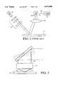
- FIG. 1A prior art high-speed imaging system is shown in FIG. 1 and includes an F- ⁇ objective 10 positioned above a sample 11 so that the surfaces of the objective are perpendicular to the sample's normal.
- a laser light source 12produces a beam 13.
- the objective 10directs the beam 13 to illuminate a spot on the sample's surface.
- An oscillating reflective surface 14is disposed at the pupil 15 of the system, between the light source 12 and the objective 10, to deflect the beam 13 back and forth along one axis.
- the sampleis placed on a table to move the sample in a direction perpendicular to the first scan direction, thereby resulting in a two dimensional scan pattern on the sample's surface.
- the objectiveis not designed for coaxial collection resulting in light reflected from the sample surface being collected by a condenser assembly 16 that is separate and apart from the objective.
- a condenser assembly 16that is separate and apart from the objective.
- Such a geometryresults in increased system footprint, increased optical complexity and a limitation of solid angle collection.
- the collected lightis then imaged on a photo-detector 17.
- the design of a classical F- ⁇ lensis primarily for monochromatic illumination. As a result, such lenses lack good polychromatic performance. Therefore, the objective 10 manifests lateral and axial chromatic aberrations over a broad band of wave-lengths.
- a second dichroic mirrorPositioned behind the first dichroic mirror is a second dichroic mirror that splits the fluorescent light into a light produced by a first probe at a first wavelength and light produced by a second probe at a second wavelength.
- the first and second wavelengthsare transmitted to respective photo-detectors.
- U.S. Pat. No. 5,296,700 to Kumagaidiscloses a fluorescent confocal microscope which includes, in pertinent part, an intermediary optical system disposed between a pair of scan mirrors and an objective optical system.
- the intermediary optical systemis designed to cancel chromatic aberrations of magnification introduced by the objective optical system.
- U.S. Pat. No. 5,260,578 to Bliton et al.discloses a scanning confocal microscope which includes, in pertinent part, two beam sources.
- One beam sourceproduces ultra violet light.
- One beam sourceproduces visible light.
- An optical assemblyis included in the common optical train to correct chromatically induced scanning errors.
- U.S. Pat. No. 5,381,224 by Dixon et al.discloses a scanning laser imaging system which allows simultaneous confocal and non-confocal imaging of reflected light from macro-size samples.
- the systemincludes, in pertinent part, a laser producing a beam which traverses a beam expander and impinges upon a single mirror disposed in an optical axis, which is defined by an F- ⁇ lens.
- the F- ⁇ lensdirects the beam onto a sample, which is disposed upon a moveable stage.
- the mirrorscans the beam along a first direction, and the stage moves the sample along a second direction, transverse to the first direction. In this manner, the beam scans across the sample in two directions.
- a beam splitterDisposed between the F- ⁇ lens and the sample is a beam splitter designed to collect light emitted from the sample.
- the beam splitterdirects a portion of light emitted from the sample onto a condenser lens, which in turn directs it onto a non-confocal detector.
- a condenser lensis required for efficient detection.
- a portion of the light passing through the beam splitteris directed along the same path as a beam by the F- ⁇ lens, forming a retrobeam.
- the F- ⁇ lensallows confocal imaging at the expense of collection efficiency, necessitating the use of the condenser to increase the numerical aperture of the collection system.
- the retro-beamimpinges upon a second beam splitter, positioned between the scan mirror and the laser.
- the second beam splitterdirects the light onto a focusing lens.
- the focusing lensis positioned proximate to a field stop, having an aperture.
- the apertureis confocal to the light emitted from the sample and selectively restricts light in the retro-beam from reaching the detector. Light traversing the aperture impinges upon a confocal detector.
- the fluorescent light collected through the F- ⁇ lensis not corrected for axial or lateral color aberrations.
- a disadvantage of the prior art systemsis that in addition to the illumination optics, additional optics are required either to scan the beam on a sample or to efficiently collect light emitted from a macro size sample, thereby increasing the systems' cost and size.
- the lensforms the objective of the system.
- the objectiveis defined as the system's lens that is closest to the sample and which has as its front focus, the sample.
- a laserproduces a collimated beam of coherent light that is directed through the objective to illuminate a spot on the sample's surface, thereby stimulating a small region of the sample to emit fluorescent light.
- the spotusually has a diameter close to the limit defined by the laws of diffraction.
- the objectivealso serves as a condenser and collects the fluorescent light emitted by the sample.
- the objectivedirects the collected light back along the identical path traveled by the incident beam, but in the opposite direction.
- a wavelength-discriminating dichroic filteris placed along the optical axis between the laser and the objective to separate the fluorescent light from the incident beam and direct the fluorescent light onto a photo-detector to produce a signal representing the sample surface emitting the fluorescent light.
- a two dimensional scanning devicewith a reflecting element having a scan center positioned at the pupil of the system, scans the spot over the entire surface of the sample.
- a display deviceis provided and synchronized with the scanning device to reproduce an image of the sample.
- FIG. 1is a simplified side view of a laser scanning microscope of the prior art.
- FIG. 2is a perspective view of optical components of the present invention.
- FIG. 3is a detailed view of a scanning beam passing through the objective shown in FIG. 2.
- FIG. 4is a simplified side view of the optical components shown on FIG. 2 including a video display system to reproduce an image of the sample in accordance with the present invention.
- FIG. 2shows a laser 18 producing an excitation/incident beam 19, which is directed through a beam expander 20. It is preferred that the laser produce a collimated beam of coherent light. However, it is possible to use a non-coherent light source optically coupled to collimating optics to create an incident light beam, e.g., a light emitting diode. If a non-coherent light source, such as an LED, is employed, a pinhole and a collimating lens would be disposed in front of the LED to create a collimated excitation/incident beam capable of being focused to a small spot.
- a non-coherent light sourcesuch as an LED
- beam 19is reflected on a two dimensional scanning device 21 and directed through an achromatic objective 22, which also serves as a condenser.
- achromatic objective 22which also serves as a condenser.
- Objective 22directs beam 19 to illuminate a region 23 of a sample 24, thereby stimulating the sample to emit light.
- Region 23may be a spot, multiple spot or a line extending across sample 24. Further, the line may be either linear or arcuate and may extend either completely across or partially across sample 23.
- the light emitted by region 23is fluorescent, which is collected by objective 22 and directed, as a retro-beam 25, back along an identical path of incident beam 19, but in an opposite direction.
- a beamsplitter 26separates retro-beam 25 from incident beam 19 and images retro-beam 25 onto a detector 27.
- Beamsplitter 26could be employed so that it transmits incident beam 19 and reflects retro-beam 25.
- incident beam 19could be reflected and retro-beam 25 transmitted, which is the preferred embodiment shown in FIG. 2.
- any type of beamsplittermay be employed, so long as it is capable of separating incident beam 19 from retro-beam 25.
- a dichroic filter, a fresnel reflector, a prism, a grating or a 50% beamsplittermay be employed.
- a polarization sensitive beamsplittermay be used to achieve the separation.
- This embodimentcould include a 1/4 waveplate positioned between the beamsplitter and the objective. This would cause incident beam 19 exiting the 1/4 waveplate to be circularly polarized. Also, additional focusing optics 28 and a back aperture 29 may be present to further shape the retro-beam 25 as desired.
- Sample 24may be illuminated point by point by scanning a spot in a raster scan fashion over the entire surface of the sample 24, to obtain a full-field image of it. Alternatively, sample 24 may be illuminated with a line scan.
- objective 22affords coaxial illumination and collection.
- objective 22is afocal in the image plane. It is preferred that objective 22 is telecentric. The telecentricity of objective 22 results in sample 24's surface always lying at a right angle with respect to the chief ray of incident beam 19, exiting objective 22.
- the objective planeis proximate to sample 24, forming an airspace therebetween which is devoid of optical elements.
- Beam 19is shown entering objective 22 at three different positions, with the chief ray of incident beam 19 having a different angle of incidence at each position. Regardless of incident beam 19's angle of incidence on objective 22, the chief ray of incident beam 19 exiting objective 22 is orthogonal to sample 24's surface.
- the achromaticity of objective 22allows it to operate over a broad band of wavelengths of light, e.g., the primary wavelength plus approximately 200 nm, or greater, while maintaining axial and lateral aberrations below the effective resolution of the system. This allows objective 22 to operate with lasers of various wavelengths and to collect light from a wide variety of fluorochromes.
- lens 1is directed to micro-imaging, which provides a small field of view, compared to lens 2.
- the small field of view provided by lens 1affords higher resolution, but increases the time necessary to scan large sample areas.
- Lens 2is directed to macro-imaging.
- lens 2provides a relatively large field of view, compared to lens 1.
- the resolution of lens 2is less than lens 1, there are advantages provided by an objective lens with large fields of view.
- an objectivecould be constructed as a zoom lens, providing fields of view of varying sizes.
- the zoom objectivemay be designed to operate in a discrete mode, affording selection of fields of view of predetermined size.
- the zoom objectivemay be designed to operate in a continuous mode, affording a range of sizes of field of view.
- an important feature of objective 22is that it defines an external pupil 29 of the system, which is positioned at the scan center.
- Any scanning mechanism that provides a two dimensional scanmay be used, e.g., a rotating polygonal mirror, rotating holographic scanner, or oscillating prisms.
- an acousto-optic deflector or a penta-prism scanning deflectormay be employed.
- the preferred embodimentis to employ a scanning system having one beam reflecting element 30 in the path of the incident beam which is pivotable about two perpendicular axes.
- the reflecting elementmay be a planar, convex, concave or polygonal mirror.
- a rotating penta-prismmay also be used.
- Reflecting element 30is not essential, however, as a refractive or diffractive deflecting elements may also be used in lieu thereof.
- Reflective element 30is supported on spindles 31 by a forked bracket 32 and, therefore, pivotable about axis A.
- Reflective element 30may be moved by any means known in the art, but is typically a galvanometer mirror.
- the bracket 32is attached at one end to wheel 33 that is driven by a stepper motor 34.
- the motor 34drives the wheel 33 to pivot reflective element 30 about axis B.
- retro-beam 25formed from fluorescent light emanating from sample 24.
- a wavelength selective filter 42may be placed in the path of retro-beam 25 between beamsplitter 26 and back aperture 29 to prevent unwanted light from impinging upon detector 27. Filter 42 would typically reject, or attenuate, light emitted by laser 18, while allowing light associated with retro-beam 25 to pass therethrough.
- Retro-beam 25is imaged on a light detector 27. Although any light detector may be used, it is preferred to use a photomultiplier tube. However, if beam 19 impinges upon region 23 as a line, then a linear array of photosensitive devices, such as a CCD array, would be employed in lieu of a photomultiplier tube. To obtain a line scan, a holographic lens, a cylindrical lens, a binary optic or any other suitable optical element 43 could be disposed in the path of incident beam 19, between objective 22 and laser 18.
- the signal from detector 27passes through electrical connections 35 to a signal processor 36 of a video display system including a video display screen 37.
- the signal from detector 27modulates the intensity of the image signal transmitted from the processor 36 through the output line 38 to the display screen 37.
- a scanning signal generator 39supplies electrical signals to the scanning apparatus 22 through electrical connections 40. Scanning apparatus 22 moves in response to generator 39's signals.
- the signal from detector 27is digitized and stored in memory and can be simultaneously scanned onto a display.
- the systemtakes advantage of detection using the conjugate focal (confocal) technique.
- retro-beam 25emanates from region 23, which corresponds to a point source of light illuminated by beam 19, with beam 19 focused to a diffraction limited spot on sample 24.
- Retro-beam 25is imaged on detector 27 after passing through back aperture 29.
- Back aperture 29isolates the detection of the system to that substantially coincident with region 23 so that back aperture 29 and region 23 are optically conjugated with each other.
- fluorescent confocal imagingis the preferred embodiment, the system may be used in a non-confocal manner. In this fashion, back aperture 29 may filter light in retro-beam 25 in either a non-confocal or semi-confocal manner. In either manner, back aperture 29 improves the signal-to-noise ratio.
- An obvious extension of the inventionis in the area of reflection imaging. That is, the reflected laser beam could be collected at the detector instead of the fluorescent beam. Both the reflected beam and the fluorescent beam could be read at the detectors if a second dichroic beamsplitter was positioned after the primary dichroic beamsplitter. Or in a like manner, multiple fluorescent labels could be detected by using multiple secondary beamsplitters and detectors.
- a non-coherent source of lightmay be employed that has an extended emission area greater than the field size of objective 22.
- no pin holewould be disposed in the path of light emitted by the non-coherent source. This allows the complete field of view of objective 22 to be filled with non-coherent light.
- Scanning mechanism 21would remain stationary.
- Focusing optics 28would define a pupil coinciding with the entrance pupil of objective 22.
- Detector 27would comprise of an array of photosensitive devices having an area equal to the field size of objective 22, multiplied by the ratio of optics 28's focal length to objective 22's focal length. In this fashion, the area of sample 24 simultaneously imaged onto detector 27 would be equal in size to the field size of objective 22.
Landscapes
- Physics & Mathematics (AREA)
- Chemical & Material Sciences (AREA)
- Analytical Chemistry (AREA)
- General Physics & Mathematics (AREA)
- Optics & Photonics (AREA)
- Investigating, Analyzing Materials By Fluorescence Or Luminescence (AREA)
- Microscoopes, Condenser (AREA)
Abstract
Description
______________________________________ Lens 1 Lens 2 ______________________________________ Scan Area (diagonal) 1 mm 1 cm Resolution 0.6 μm 10 μm Numerical Aperture 0.75 0.25 Intensity Uniformity 95% 95% Spatial Uniformity 98% 98% Polychromatic Range 500--750 nm 500--750 nm Thru focus sensitivity 1% (signal 1% (signal change over change over 20 μm) 100 μm) Field Flatness Variation +/-10 μm +/-20 μm Working Distance 3 mm 3.5 mm ______________________________________
Claims (30)
Priority Applications (1)
| Application Number | Priority Date | Filing Date | Title |
|---|---|---|---|
| US08/616,174US5672880A (en) | 1994-12-08 | 1996-03-15 | Fluoresecence imaging system |
Applications Claiming Priority (2)
| Application Number | Priority Date | Filing Date | Title |
|---|---|---|---|
| US35160394A | 1994-12-08 | 1994-12-08 | |
| US08/616,174US5672880A (en) | 1994-12-08 | 1996-03-15 | Fluoresecence imaging system |
Related Parent Applications (1)
| Application Number | Title | Priority Date | Filing Date |
|---|---|---|---|
| US35160394AContinuation-In-Part | 1994-12-08 | 1994-12-08 |
Publications (1)
| Publication Number | Publication Date |
|---|---|
| US5672880Atrue US5672880A (en) | 1997-09-30 |
Family
ID=23381580
Family Applications (2)
| Application Number | Title | Priority Date | Filing Date |
|---|---|---|---|
| US08/616,772Expired - LifetimeUS5719391A (en) | 1994-12-08 | 1996-03-15 | Fluorescence imaging system employing a macro scanning objective |
| US08/616,174Expired - LifetimeUS5672880A (en) | 1994-12-08 | 1996-03-15 | Fluoresecence imaging system |
Family Applications Before (1)
| Application Number | Title | Priority Date | Filing Date |
|---|---|---|---|
| US08/616,772Expired - LifetimeUS5719391A (en) | 1994-12-08 | 1996-03-15 | Fluorescence imaging system employing a macro scanning objective |
Country Status (6)
| Country | Link |
|---|---|
| US (2) | US5719391A (en) |
| EP (1) | EP0746865B1 (en) |
| JP (1) | JP3794703B2 (en) |
| AU (1) | AU3963595A (en) |
| DE (1) | DE69530072T2 (en) |
| WO (1) | WO1996018205A1 (en) |
Cited By (96)
| Publication number | Priority date | Publication date | Assignee | Title |
|---|---|---|---|---|
| US5943129A (en)* | 1997-08-07 | 1999-08-24 | Cambridge Research & Instrumentation Inc. | Fluorescence imaging system |
| WO1999042884A1 (en)* | 1998-02-19 | 1999-08-26 | Leica Microsystems Heidelberg Gmbh | Optical arrangement with a spectrally selective element |
| US5981956A (en)* | 1996-05-16 | 1999-11-09 | Affymetrix, Inc. | Systems and methods for detection of labeled materials |
| US6075613A (en)* | 1999-02-26 | 2000-06-13 | General Scanning, Inc. | Optical scanner calibration device |
| US6078390A (en)* | 1998-05-04 | 2000-06-20 | General Scanning, Inc. | Scanning system and method of operation for automatically setting detection sensitivity |
| US6124928A (en)* | 1997-03-07 | 2000-09-26 | Kaiser Optical Systems, Inc. | Methods and apparatus for obtaining a selectively polarized induced emission |
| US6140653A (en)* | 1998-03-27 | 2000-10-31 | Vysis, Inc. | Large-field fluorescence imaging apparatus |
| US6143535A (en)* | 1997-03-27 | 2000-11-07 | Palsson; Bernhard O. | Targeted system for removing tumor cells from cell populations |
| US6185030B1 (en) | 1998-03-20 | 2001-02-06 | James W. Overbeck | Wide field of view and high speed scanning microscopy |
| US6201639B1 (en) | 1998-03-20 | 2001-03-13 | James W. Overbeck | Wide field of view and high speed scanning microscopy |
| US6317207B2 (en) | 1999-02-23 | 2001-11-13 | Ljl Biosystems, Inc. | Frequency-domain light detection device |
| US6326605B1 (en) | 1998-02-20 | 2001-12-04 | Ljl Biosystems, Inc. | Broad range light detection system |
| US6355934B1 (en) | 1999-02-26 | 2002-03-12 | Packard Biochip Technologies | Imaging system for an optical scanner |
| US6355938B1 (en) | 1998-11-25 | 2002-03-12 | Phormax Corporation | Phosphor screen scanning systems |
| US6455861B1 (en) | 1998-11-24 | 2002-09-24 | Cambridge Research & Instrumentation, Inc. | Fluorescence polarization assay system and method |
| US6466316B2 (en) | 1998-07-27 | 2002-10-15 | Ljl Biosystems, Inc. | Apparatus and methods for spectroscopic measurements |
| US6469311B1 (en) | 1997-07-16 | 2002-10-22 | Molecular Devices Corporation | Detection device for light transmitted from a sensed volume |
| US6472671B1 (en) | 2000-02-09 | 2002-10-29 | Jean I. Montagu | Quantified fluorescence microscopy |
| US6483582B2 (en) | 1998-07-27 | 2002-11-19 | Ljl Biosystems, Inc. | Apparatus and methods for time-resolved spectroscopic measurements |
| US20020192808A1 (en)* | 1998-05-16 | 2002-12-19 | Gambini Michael R. | Instrument for monitoring polymerase chain reaction of DNA |
| US6499366B1 (en) | 1997-07-16 | 2002-12-31 | Ljl Biosystems, Inc. | Sample feeder |
| US20030010930A1 (en)* | 2001-06-07 | 2003-01-16 | Jena-Optronik Gmbh | Arrangement for the optical excitation of fluorescent radiation of individual specimens on a multispecimen carrier |
| US20030017081A1 (en)* | 1994-02-10 | 2003-01-23 | Affymetrix, Inc. | Method and apparatus for imaging a sample on a device |
| US6514722B2 (en) | 1997-03-27 | 2003-02-04 | Oncosis | Method and apparatus for selectively targeting specific cells within a cell population |
| US6534308B1 (en) | 1997-03-27 | 2003-03-18 | Oncosis, Llc | Method and apparatus for selectively targeting specific cells within a mixed cell population |
| US6576476B1 (en) | 1998-09-02 | 2003-06-10 | Ljl Biosystems, Inc. | Chemiluminescence detection method and device |
| US6580081B1 (en)* | 1999-08-02 | 2003-06-17 | Jena-Optronik Gmbh | Arrangement for the detection of fluorescene radiation of matrix-shaped speciman carriers |
| US20030143580A1 (en)* | 2001-09-06 | 2003-07-31 | Don Straus | Rapid and sensitive detection of molecules |
| US6642018B1 (en) | 1998-03-27 | 2003-11-04 | Oncosis Llc | Method for inducing a response in one or more targeted cells |
| US20030211009A1 (en)* | 2001-05-18 | 2003-11-13 | Buchanan Kris S. | Rapid multi-material sample input system |
| US20040002154A1 (en)* | 2002-04-19 | 2004-01-01 | Palsson Bernhard O. | Methods for preparing libraries of unique tags and related screening methods |
| US6680796B2 (en)* | 2000-06-23 | 2004-01-20 | Leica Microsystems Heidelberg, Gmbh | Microscope assemblage |
| US20040014202A1 (en)* | 2001-11-29 | 2004-01-22 | King Howard G. | Apparatus and method for differentiating multiple fluorescence signals by excitation wavelength |
| FR2842407A1 (en)* | 2002-07-18 | 2004-01-23 | Mauna Kea Technologies | "METHOD AND APPARATUS OF FIBROUS CONFOCAL FLUORESCENCE IMAGING" |
| US20040038390A1 (en)* | 1999-05-17 | 2004-02-26 | Boege Steven J. | Optical instrument including excitation source |
| US20040072335A1 (en)* | 1999-05-17 | 2004-04-15 | Boege Steven J. | Optical instrument including excitation source |
| WO2004025331A3 (en)* | 2002-09-16 | 2004-05-13 | Rensselaer Polytech Inst | Microscope with extended field of vision |
| US20040096883A1 (en)* | 1994-02-10 | 2004-05-20 | Affymetrix, Inc., A California Corporation | Scanned image alignment systems and methods |
| US6741344B1 (en) | 1994-02-10 | 2004-05-25 | Affymetrix, Inc. | Method and apparatus for detection of fluorescently labeled materials |
| US20040180437A1 (en)* | 1997-03-27 | 2004-09-16 | Oncosis Llc | Optoinjection methods |
| US6804385B2 (en) | 2000-10-24 | 2004-10-12 | Oncosis | Method and device for selectively targeting cells within a three-dimensional specimen |
| US20040224421A1 (en)* | 2000-06-15 | 2004-11-11 | Deweerd Herman | Bi-directional scanning method |
| US6825921B1 (en) | 1999-11-10 | 2004-11-30 | Molecular Devices Corporation | Multi-mode light detection system |
| US20040247485A1 (en)* | 2003-06-03 | 2004-12-09 | Jorg Kraus | Optical substrate for enhanced detectability of fluorescence |
| US20050012057A1 (en)* | 2003-05-08 | 2005-01-20 | Alara, Inc. | Method and apparatus for radiation image erasure |
| US20050051733A1 (en)* | 2003-06-06 | 2005-03-10 | Unaxis Balzers Ltd. | Optical device for surface-generated fluorescence |
| US20050202558A1 (en)* | 2004-03-15 | 2005-09-15 | Koller Manfred R. | Methods for purification of cells based on product secretion |
| US20050279949A1 (en)* | 1999-05-17 | 2005-12-22 | Applera Corporation | Temperature control for light-emitting diode stabilization |
| US6982431B2 (en) | 1998-08-31 | 2006-01-03 | Molecular Devices Corporation | Sample analysis systems |
| US6992761B2 (en) | 1997-09-20 | 2006-01-31 | Molecular Devices Corporation | Broad range light detection system |
| US7024316B1 (en) | 1999-10-21 | 2006-04-04 | Dakocytomation Colorado, Inc. | Transiently dynamic flow cytometer analysis system |
| US20060094048A1 (en)* | 2004-10-29 | 2006-05-04 | Affymetrix, Inc. | System, method, and product for multiple wavelength detection using single source excitation |
| US20060121602A1 (en)* | 2001-11-29 | 2006-06-08 | Hoshizaki Jon A | Optical scanning configurations, systems, and methods |
| US7094527B2 (en) | 2000-11-29 | 2006-08-22 | Xy, Inc. | System for in-vitro fertilization with spermatozoa separated into X-chromosome and Y-chromosome bearing populations |
| US20060194308A1 (en)* | 2005-01-18 | 2006-08-31 | Roche Diagnostics Operations, Inc. | Imaging fluorescence signals using telecentricity |
| US20060209309A1 (en)* | 2005-03-18 | 2006-09-21 | Illumina, Inc. | Systems for and methods of facilitating focusing an optical scanner |
| US7169548B2 (en) | 2002-09-13 | 2007-01-30 | Xy, Inc. | Sperm cell processing and preservation systems |
| US7195920B2 (en) | 1997-12-31 | 2007-03-27 | Xy, Inc. | Collection systems for cytometer sorting of sperm |
| US7208265B1 (en) | 1999-11-24 | 2007-04-24 | Xy, Inc. | Method of cryopreserving selected sperm cells |
| US7221453B2 (en) | 1997-01-31 | 2007-05-22 | Xy, Inc. | Optical apparatus |
| US20070146696A1 (en)* | 1991-04-02 | 2007-06-28 | Minori Noguchi | Apparatus and method for testing defects |
| US20070212747A1 (en)* | 2005-09-26 | 2007-09-13 | Rapid Micro Biosystems | Cassette containing growth medium |
| US20070238161A1 (en)* | 1998-05-16 | 2007-10-11 | Applera Corporation | Instrument for monitoring polymerase chain reaction of DNA |
| US20070269875A1 (en)* | 2003-10-31 | 2007-11-22 | Koller Manfred R | Method and apparatus for cell permeabilization |
| US7371517B2 (en) | 2000-05-09 | 2008-05-13 | Xy, Inc. | High purity X-chromosome bearing and Y-chromosome bearing populations of spermatozoa |
| US7498164B2 (en) | 1998-05-16 | 2009-03-03 | Applied Biosystems, Llc | Instrument for monitoring nucleic acid sequence amplification reaction |
| US20090117006A1 (en)* | 2007-11-01 | 2009-05-07 | Complete Genomics, Inc. | Structures for enhanced detection of fluorescence |
| US7618770B2 (en) | 2005-07-29 | 2009-11-17 | Xy, Inc. | Methods and apparatus for reducing protein content in sperm cell extenders |
| US20090287421A1 (en)* | 2004-07-27 | 2009-11-19 | George C Malachowski | Enhancing Flow Cytometry Discrimination with Geometric Transformation |
| US7629113B2 (en) | 1997-12-31 | 2009-12-08 | Xy, Inc | Multiple sexed embryo production system for bovine mammals |
| US7713687B2 (en) | 2000-11-29 | 2010-05-11 | Xy, Inc. | System to separate frozen-thawed spermatozoa into x-chromosome bearing and y-chromosome bearing populations |
| US7723116B2 (en) | 2003-05-15 | 2010-05-25 | Xy, Inc. | Apparatus, methods and processes for sorting particles and for providing sex-sorted animal sperm |
| US20100161266A1 (en)* | 2008-12-19 | 2010-06-24 | Affymetrix, Inc. | System, method and product for calibrating inspection tools |
| US20100179310A1 (en)* | 2009-01-09 | 2010-07-15 | Cyntellect, Inc. | Genetic analysis of cells |
| US7758811B2 (en) | 2003-03-28 | 2010-07-20 | Inguran, Llc | System for analyzing particles using multiple flow cytometry units |
| US7772005B1 (en) | 1998-07-30 | 2010-08-10 | Xy, Llc | Method of establishing an equine artificial insemination sample |
| US20100216143A1 (en)* | 2002-05-17 | 2010-08-26 | Life Technology Corporation | Apparatus and Method for Differentiating Multiple Fluorescence Signals by Excitation Wavelength |
| US7833147B2 (en) | 2004-07-22 | 2010-11-16 | Inguran, LLC. | Process for enriching a population of sperm cells |
| US7838210B2 (en) | 2004-03-29 | 2010-11-23 | Inguran, LLC. | Sperm suspensions for sorting into X or Y chromosome-bearing enriched populations |
| US7855078B2 (en) | 2002-08-15 | 2010-12-21 | Xy, Llc | High resolution flow cytometer |
| US8055098B2 (en) | 2006-01-27 | 2011-11-08 | Affymetrix, Inc. | System, method, and product for imaging probe arrays with small feature sizes |
| US8211629B2 (en) | 2002-08-01 | 2012-07-03 | Xy, Llc | Low pressure sperm cell separation system |
| US8233735B2 (en) | 1994-02-10 | 2012-07-31 | Affymetrix, Inc. | Methods and apparatus for detection of fluorescently labeled materials |
| US8351026B2 (en) | 2005-04-22 | 2013-01-08 | Affymetrix, Inc. | Methods and devices for reading microarrays |
| US8486618B2 (en) | 2002-08-01 | 2013-07-16 | Xy, Llc | Heterogeneous inseminate system |
| US20140168639A1 (en)* | 2012-12-13 | 2014-06-19 | Seok-Joo Lee | Laser patterning examining apparatus |
| US8788213B2 (en) | 2009-01-12 | 2014-07-22 | Intrexon Corporation | Laser mediated sectioning and transfer of cell colonies |
| US9445025B2 (en) | 2006-01-27 | 2016-09-13 | Affymetrix, Inc. | System, method, and product for imaging probe arrays with small feature sizes |
| US9551026B2 (en) | 2007-12-03 | 2017-01-24 | Complete Genomincs, Inc. | Method for nucleic acid detection using voltage enhancement |
| US9643180B2 (en) | 2008-09-24 | 2017-05-09 | First Light Biosciences, Inc. | Method for detecting analytes |
| US9745546B2 (en) | 2011-11-07 | 2017-08-29 | Rapid Micro Biosystems, Inc. | Cassette for sterility testing |
| CN109444192A (en)* | 2018-11-27 | 2019-03-08 | 金华职业技术学院 | A kind of high pressure sample test device of pulsed laser heating |
| US10407707B2 (en) | 2012-04-16 | 2019-09-10 | Rapid Micro Biosystems, Inc. | Cell culturing device |
| US11835437B2 (en) | 2011-11-02 | 2023-12-05 | Complete Genomics, Inc. | Treatment for stabilizing nucleic acid arrays |
| US12031985B2 (en) | 2018-04-19 | 2024-07-09 | First Light Diagnostics, Inc. | Detection of targets |
| US12287332B2 (en) | 2018-10-04 | 2025-04-29 | First Light Diagnostics, Inc. | Test cartridges |
Families Citing this family (62)
| Publication number | Priority date | Publication date | Assignee | Title |
|---|---|---|---|---|
| US7215424B1 (en) | 1998-03-03 | 2007-05-08 | J.A. Woollam Co., Inc. | Broadband ellipsometer or polarimeter system including at least one multiple element lens |
| US7518725B1 (en) | 1995-09-20 | 2009-04-14 | J.A. Woollam Co., Inc. | Temperature controlled lens |
| AU2445697A (en)* | 1996-04-08 | 1997-10-29 | Liberty Technologies, Inc. | Storage phosphor erasure using yellow and/or infrared |
| CA2263226C (en)* | 1996-08-16 | 2006-10-10 | Imaging Research, Inc. | A digital imaging system for assays in well plates, gels and blots |
| US6043506A (en)* | 1997-08-13 | 2000-03-28 | Bio-Rad Laboratories, Inc. | Multi parameter scanner |
| US6051835A (en)* | 1998-01-07 | 2000-04-18 | Bio-Rad Laboratories, Inc. | Spectral imaging apparatus and methodology |
| US6627446B1 (en) | 1998-07-02 | 2003-09-30 | Amersham Biosciences (Sv) Corp | Robotic microchannel bioanalytical instrument |
| DE19923822A1 (en)† | 1999-05-19 | 2000-11-23 | Zeiss Carl Jena Gmbh | Optical scanning configuration for detecting fluorescent light and for suppressing stray light arising from an illuminated test detected through a lens creates a shaded area for stray light in a focal plane. |
| WO2001009592A1 (en)* | 1999-07-30 | 2001-02-08 | California Institute Of Technology | System and method for monitoring cellular activity |
| EP1311824A4 (en) | 2000-06-25 | 2010-12-08 | Affymetrix Inc | Optically active substrates |
| EP1345026B1 (en) | 2002-03-15 | 2010-05-05 | Affymetrix, Inc. | System and method for scanning of biological materials |
| US7317415B2 (en) | 2003-08-08 | 2008-01-08 | Affymetrix, Inc. | System, method, and product for scanning of biological materials employing dual analog integrators |
| DE10344060A1 (en)* | 2003-09-23 | 2005-05-04 | Zeiss Carl Jena Gmbh | Confocal laser scanning microscope |
| US6940641B2 (en)* | 2003-11-18 | 2005-09-06 | Olympus Corporation | Fluorescence observation apparatus |
| DE102004008762B4 (en)* | 2004-02-23 | 2006-10-12 | Erwin Kayser-Threde Gmbh | Method and device for detecting and identifying bioparticles |
| US7397042B2 (en)* | 2005-08-24 | 2008-07-08 | Dr. Chip Biotechnology Incorporation | Optical detection apparatus and method thereof |
| US7329860B2 (en)* | 2005-11-23 | 2008-02-12 | Illumina, Inc. | Confocal imaging methods and apparatus |
| US7846391B2 (en) | 2006-05-22 | 2010-12-07 | Lumencor, Inc. | Bioanalytical instrumentation using a light source subsystem |
| US9255348B2 (en) | 2006-08-25 | 2016-02-09 | The Trustees Of Columbia University In The City Of New York | Systems and methods for biodosimetry with biochip using gene expression signatures |
| US7826977B2 (en)* | 2006-08-25 | 2010-11-02 | The Trustees Of Columbia University In The City Of New York | Systems and methods for high-speed image scanning |
| US7813013B2 (en)* | 2006-11-21 | 2010-10-12 | Illumina, Inc. | Hexagonal site line scanning method and system |
| US7791013B2 (en)* | 2006-11-21 | 2010-09-07 | Illumina, Inc. | Biological microarray line scanning method and system |
| US8098375B2 (en) | 2007-08-06 | 2012-01-17 | Lumencor, Inc. | Light emitting diode illumination system |
| US8242462B2 (en) | 2009-01-23 | 2012-08-14 | Lumencor, Inc. | Lighting design of high quality biomedical devices |
| US9767342B2 (en) | 2009-05-22 | 2017-09-19 | Affymetrix, Inc. | Methods and devices for reading microarrays |
| US9791313B2 (en) | 2010-12-01 | 2017-10-17 | MKS Technology | Spectrometer |
| US8389957B2 (en) | 2011-01-14 | 2013-03-05 | Lumencor, Inc. | System and method for metered dosage illumination in a bioanalysis or other system |
| US8466436B2 (en) | 2011-01-14 | 2013-06-18 | Lumencor, Inc. | System and method for metered dosage illumination in a bioanalysis or other system |
| US8967811B2 (en) | 2012-01-20 | 2015-03-03 | Lumencor, Inc. | Solid state continuous white light source |
| US9217561B2 (en) | 2012-06-15 | 2015-12-22 | Lumencor, Inc. | Solid state light source for photocuring |
| DE102012111601A1 (en)* | 2012-11-29 | 2014-03-13 | Limo Patentverwaltung Gmbh & Co. Kg | Scanning device for scanning a laser beam in a working plane |
| EP3004819A4 (en)* | 2013-05-31 | 2017-05-24 | MKS Technology Inc. | Spectrometer |
| EP3039409B1 (en) | 2013-08-28 | 2017-11-08 | Illumina, Inc. | Optical alignment tool |
| US10540783B2 (en) | 2013-11-01 | 2020-01-21 | Illumina, Inc. | Image analysis useful for patterned objects |
| CN106536734B (en) | 2014-05-16 | 2020-12-22 | Illumina公司 | Nucleic acid synthesis technology |
| CA2960721C (en) | 2014-10-09 | 2023-09-05 | Illumina, Inc. | Method and device for separating immiscible liquids to effectively isolate at least one of the liquids |
| TWI689720B (en)* | 2017-01-07 | 2020-04-01 | 美商伊路米納有限公司 | Solid inspection apparatus and method of use |
| GB201701691D0 (en) | 2017-02-01 | 2017-03-15 | Illumina Inc | System and method with reflective fiducials |
| GB201701689D0 (en) | 2017-02-01 | 2017-03-15 | Illumia Inc | System and method with fiducials of non-closed shapes |
| SG11201906442TA (en) | 2017-02-01 | 2019-08-27 | Illumina Inc | System and method with fiducials responding to multiple excitation frequencies |
| GB201701686D0 (en) | 2017-02-01 | 2017-03-15 | Illunina Inc | System & method with fiducials having offset layouts |
| GB201701688D0 (en) | 2017-02-01 | 2017-03-15 | Illumia Inc | System and method with fiducials in non-recliner layouts |
| US12437844B2 (en) | 2017-03-30 | 2025-10-07 | Illumina, Inc. | Genomic data analysis system and method |
| NL2023316B1 (en) | 2019-03-21 | 2020-09-28 | Illumina Inc | Artificial intelligence-based sequencing |
| NL2023314B1 (en) | 2019-03-21 | 2020-09-28 | Illumina Inc | Artificial intelligence-based quality scoring |
| NL2023310B1 (en) | 2019-03-21 | 2020-09-28 | Illumina Inc | Training data generation for artificial intelligence-based sequencing |
| NL2023312B1 (en) | 2019-03-21 | 2020-09-28 | Illumina Inc | Artificial intelligence-based base calling |
| US11210554B2 (en) | 2019-03-21 | 2021-12-28 | Illumina, Inc. | Artificial intelligence-based generation of sequencing metadata |
| NL2023311B9 (en) | 2019-03-21 | 2021-03-12 | Illumina Inc | Artificial intelligence-based generation of sequencing metadata |
| WO2020191389A1 (en) | 2019-03-21 | 2020-09-24 | Illumina, Inc. | Training data generation for artificial intelligence-based sequencing |
| US12354008B2 (en) | 2020-02-20 | 2025-07-08 | Illumina, Inc. | Knowledge distillation and gradient pruning-based compression of artificial intelligence-based base caller |
| US11188778B1 (en) | 2020-05-05 | 2021-11-30 | Illumina, Inc. | Equalization-based image processing and spatial crosstalk attenuator |
| CA3224034A1 (en) | 2021-06-25 | 2022-12-29 | Helge Nareid | Linear fourier fiducial |
| US20220414853A1 (en) | 2021-06-25 | 2022-12-29 | Illumina, Inc. | Fiducials for use in registration of a patterned surface |
| US11455487B1 (en) | 2021-10-26 | 2022-09-27 | Illumina Software, Inc. | Intensity extraction and crosstalk attenuation using interpolation and adaptation for base calling |
| EP4374343A1 (en) | 2021-07-19 | 2024-05-29 | Illumina, Inc. | Intensity extraction with interpolation and adaptation for base calling |
| US20230088338A1 (en) | 2021-09-10 | 2023-03-23 | Illumina, Inc. | Sequencer focus quality metrics and focus tracking for periodically patterned surfaces |
| WO2023049212A2 (en) | 2021-09-22 | 2023-03-30 | Illumina, Inc. | State-based base calling |
| US20230343414A1 (en) | 2022-03-25 | 2023-10-26 | Illumina, Inc. | Sequence-to-sequence base calling |
| EP4537344A1 (en) | 2022-06-09 | 2025-04-16 | Illumina, Inc. | Dependence of base calling on flow cell tilt |
| US20240033738A1 (en) | 2022-07-27 | 2024-02-01 | Illumina, Inc. | Flow cell based motion system calibration and control methods |
| EP4594012A1 (en) | 2022-09-26 | 2025-08-06 | Illumina, Inc. | Flow cell based motion system calibration and control methods |
Citations (6)
| Publication number | Priority date | Publication date | Assignee | Title |
|---|---|---|---|---|
| US4284897A (en)* | 1977-04-30 | 1981-08-18 | Olympus Optical Company Ltd. | Fluorescence determining microscope utilizing laser light |
| US4877965A (en)* | 1985-07-01 | 1989-10-31 | Diatron Corporation | Fluorometer |
| US5022757A (en)* | 1989-01-23 | 1991-06-11 | Modell Mark D | Heterodyne system and method for sensing a target substance |
| US5192980A (en)* | 1990-06-27 | 1993-03-09 | A. E. Dixon | Apparatus and method for method for spatially- and spectrally-resolved measurements |
| US5381224A (en)* | 1993-08-30 | 1995-01-10 | A. E. Dixon | Scanning laser imaging system |
| US5504336A (en)* | 1993-05-18 | 1996-04-02 | Fuji Photo Film Co., Ltd. | Spectrofluorometric apparatus for obtaining spectral image information |
Family Cites Families (8)
| Publication number | Priority date | Publication date | Assignee | Title |
|---|---|---|---|---|
| US3657537A (en)* | 1970-04-03 | 1972-04-18 | Bausch & Lomb | Computerized slit-scan cyto-fluorometer for automated cell recognition |
| US4058732A (en)* | 1975-06-30 | 1977-11-15 | Analytical Radiation Corporation | Method and apparatus for improved analytical fluorescent spectroscopy |
| DE3422143A1 (en)* | 1984-06-14 | 1985-12-19 | Josef Prof. Dr. Bille | WAFER INSPECTION DEVICE |
| US5144477A (en)* | 1988-04-11 | 1992-09-01 | Medical Research Council | Method of operating a scanning confocal imaging system |
| US4945287A (en)* | 1988-06-13 | 1990-07-31 | Eotron Corporation | Multiple pentaprism scanning device and method |
| US5260578A (en)* | 1991-04-10 | 1993-11-09 | Mayo Foundation For Medical Education And Research | Confocal imaging system for visible and ultraviolet light |
| US5184012A (en)* | 1991-12-26 | 1993-02-02 | Olympus Optical Co., Ltd. | Optical scanning apparatus with axis deviation correction |
| JPH05203878A (en)* | 1992-01-27 | 1993-08-13 | Jeol Ltd | Scanning laser microscope |
- 1995
- 1995-10-20JPJP51757596Apatent/JP3794703B2/ennot_activeExpired - Fee Related
- 1995-10-20DEDE69530072Tpatent/DE69530072T2/ennot_activeExpired - Lifetime
- 1995-10-20EPEP95937560Apatent/EP0746865B1/ennot_activeExpired - Lifetime
- 1995-10-20WOPCT/US1995/013531patent/WO1996018205A1/enactiveIP Right Grant
- 1995-10-20AUAU39635/95Apatent/AU3963595A/ennot_activeAbandoned
- 1996
- 1996-03-15USUS08/616,772patent/US5719391A/ennot_activeExpired - Lifetime
- 1996-03-15USUS08/616,174patent/US5672880A/ennot_activeExpired - Lifetime
Patent Citations (6)
| Publication number | Priority date | Publication date | Assignee | Title |
|---|---|---|---|---|
| US4284897A (en)* | 1977-04-30 | 1981-08-18 | Olympus Optical Company Ltd. | Fluorescence determining microscope utilizing laser light |
| US4877965A (en)* | 1985-07-01 | 1989-10-31 | Diatron Corporation | Fluorometer |
| US5022757A (en)* | 1989-01-23 | 1991-06-11 | Modell Mark D | Heterodyne system and method for sensing a target substance |
| US5192980A (en)* | 1990-06-27 | 1993-03-09 | A. E. Dixon | Apparatus and method for method for spatially- and spectrally-resolved measurements |
| US5504336A (en)* | 1993-05-18 | 1996-04-02 | Fuji Photo Film Co., Ltd. | Spectrofluorometric apparatus for obtaining spectral image information |
| US5381224A (en)* | 1993-08-30 | 1995-01-10 | A. E. Dixon | Scanning laser imaging system |
Non-Patent Citations (2)
| Title |
|---|
| Richard L. Shoemaker et al., "An Ultrafast Laser Scanner Microscope for Digital Image Analysis", IEEE Transactions on Biomedical Engineering, vol. BME-29, No. 2, pp. 82-91, (Feb. 1982). |
| Richard L. Shoemaker et al., An Ultrafast Laser Scanner Microscope for Digital Image Analysis , IEEE Transactions on Biomedical Engineering , vol. BME 29, No. 2, pp. 82 91, (Feb. 1982).* |
Cited By (232)
| Publication number | Priority date | Publication date | Assignee | Title |
|---|---|---|---|---|
| US7940383B2 (en) | 1991-04-02 | 2011-05-10 | Hitachi, Ltd. | Method of detecting defects on an object |
| US20070146696A1 (en)* | 1991-04-02 | 2007-06-28 | Minori Noguchi | Apparatus and method for testing defects |
| US20100088042A1 (en)* | 1991-04-02 | 2010-04-08 | Minori Noguchi | Apparatus And Method For Testing Defects |
| US7639350B2 (en)* | 1991-04-02 | 2009-12-29 | Hitachi, Ltd | Apparatus and method for testing defects |
| US20030152490A1 (en)* | 1994-02-10 | 2003-08-14 | Mark Trulson | Method and apparatus for imaging a sample on a device |
| US20030017081A1 (en)* | 1994-02-10 | 2003-01-23 | Affymetrix, Inc. | Method and apparatus for imaging a sample on a device |
| US6741344B1 (en) | 1994-02-10 | 2004-05-25 | Affymetrix, Inc. | Method and apparatus for detection of fluorescently labeled materials |
| US20040048362A1 (en)* | 1994-02-10 | 2004-03-11 | Mark Trulson | Method and apparatus for imaging a sample on a device |
| US20040096883A1 (en)* | 1994-02-10 | 2004-05-20 | Affymetrix, Inc., A California Corporation | Scanned image alignment systems and methods |
| US20040253714A1 (en)* | 1994-02-10 | 2004-12-16 | Affymetrix, Inc. | Thermal and fluidic cycling device for nucleic acid hybridization |
| US20040196456A1 (en)* | 1994-02-10 | 2004-10-07 | Affymetrix, Inc. | Method and apparatus for detection of fluorescently labeled materials |
| US20060111850A1 (en)* | 1994-02-10 | 2006-05-25 | Affymetrix, Inc. | Method and apparatus for detection of fluorescently labeled materials |
| US8233735B2 (en) | 1994-02-10 | 2012-07-31 | Affymetrix, Inc. | Methods and apparatus for detection of fluorescently labeled materials |
| US20050200948A1 (en)* | 1994-02-10 | 2005-09-15 | Affymetrix, Inc. | Method and apparatus for imaging a sample on a device |
| US20050037367A9 (en)* | 1994-02-10 | 2005-02-17 | Affymetrix, Inc., A California Corporation | Scanned image alignment systems and methods |
| US6207960B1 (en)* | 1996-05-16 | 2001-03-27 | Affymetrix, Inc | System and methods for detection of labeled materials |
| US6597000B2 (en) | 1996-05-16 | 2003-07-22 | Affymetrix, Inc. | Systems and methods for detection of labeled materials |
| US5981956A (en)* | 1996-05-16 | 1999-11-09 | Affymetrix, Inc. | Systems and methods for detection of labeled materials |
| US7929137B2 (en) | 1997-01-31 | 2011-04-19 | Xy, Llc | Optical apparatus |
| US7221453B2 (en) | 1997-01-31 | 2007-05-22 | Xy, Inc. | Optical apparatus |
| US7586604B2 (en) | 1997-01-31 | 2009-09-08 | Xy, Inc. | Optical apparatus |
| US6124928A (en)* | 1997-03-07 | 2000-09-26 | Kaiser Optical Systems, Inc. | Methods and apparatus for obtaining a selectively polarized induced emission |
| US20110201075A1 (en)* | 1997-03-27 | 2011-08-18 | Cyntellect, Inc. | Optoinjection methods |
| US6143535A (en)* | 1997-03-27 | 2000-11-07 | Palsson; Bernhard O. | Targeted system for removing tumor cells from cell populations |
| US7505618B2 (en) | 1997-03-27 | 2009-03-17 | Cyntellect, Inc. | Method and apparatus for selectively targeting specific cells within a cell population |
| US20040180437A1 (en)* | 1997-03-27 | 2004-09-16 | Oncosis Llc | Optoinjection methods |
| US20030180902A1 (en)* | 1997-03-27 | 2003-09-25 | Palsson Bernhard O. | Method and apparatus for selectively targeting specific cells within a mixed cell population |
| US7129070B2 (en) | 1997-03-27 | 2006-10-31 | Cyntellect, Inc. | Targeted system for removing tumor cells from cell populations |
| US6514722B2 (en) | 1997-03-27 | 2003-02-04 | Oncosis | Method and apparatus for selectively targeting specific cells within a cell population |
| US6534308B1 (en) | 1997-03-27 | 2003-03-18 | Oncosis, Llc | Method and apparatus for selectively targeting specific cells within a mixed cell population |
| US20030219892A1 (en)* | 1997-03-27 | 2003-11-27 | Palsson Bernhard O. | Method and apparatus for selectively targeting specific cells within a cell population |
| US7300795B2 (en) | 1997-03-27 | 2007-11-27 | Cyntellect, Inc. | Optoinjection methods |
| US8401263B2 (en) | 1997-03-27 | 2013-03-19 | Intrexon Corporation | Method and apparatus for selectively targeting specific cells within a cell population |
| US20030138923A1 (en)* | 1997-03-27 | 2003-07-24 | Palsson Bernhard O. | Targeted system for removing tumor cells from cell populations |
| US6469311B1 (en) | 1997-07-16 | 2002-10-22 | Molecular Devices Corporation | Detection device for light transmitted from a sensed volume |
| US6499366B1 (en) | 1997-07-16 | 2002-12-31 | Ljl Biosystems, Inc. | Sample feeder |
| US5943129A (en)* | 1997-08-07 | 1999-08-24 | Cambridge Research & Instrumentation Inc. | Fluorescence imaging system |
| US6992761B2 (en) | 1997-09-20 | 2006-01-31 | Molecular Devices Corporation | Broad range light detection system |
| US20060258002A1 (en)* | 1997-12-11 | 2006-11-16 | Affymetrix, Inc. | Scanned image alignment systems and methods |
| US9365822B2 (en) | 1997-12-31 | 2016-06-14 | Xy, Llc | System and method for sorting cells |
| US9422523B2 (en) | 1997-12-31 | 2016-08-23 | Xy, Llc | System and method for sorting cells |
| US7195920B2 (en) | 1997-12-31 | 2007-03-27 | Xy, Inc. | Collection systems for cytometer sorting of sperm |
| US7629113B2 (en) | 1997-12-31 | 2009-12-08 | Xy, Inc | Multiple sexed embryo production system for bovine mammals |
| US6510001B1 (en) | 1998-02-19 | 2003-01-21 | Leica Microsystems Heidelberg Gmbh | Optical arrangement with a spectrally selective element |
| US20030133189A1 (en)* | 1998-02-19 | 2003-07-17 | Leica Microsystems Heidelberg Gmbh | Optical arrangement |
| US6654165B2 (en)* | 1998-02-19 | 2003-11-25 | Leica Microsystems Heidelberg Gmbh | Optical arrangement |
| WO1999042884A1 (en)* | 1998-02-19 | 1999-08-26 | Leica Microsystems Heidelberg Gmbh | Optical arrangement with a spectrally selective element |
| US6326605B1 (en) | 1998-02-20 | 2001-12-04 | Ljl Biosystems, Inc. | Broad range light detection system |
| US6498335B2 (en) | 1998-02-20 | 2002-12-24 | Ljl Biosystems, Inc. | Broad range light detection system |
| US6185030B1 (en) | 1998-03-20 | 2001-02-06 | James W. Overbeck | Wide field of view and high speed scanning microscopy |
| US6201639B1 (en) | 1998-03-20 | 2001-03-13 | James W. Overbeck | Wide field of view and high speed scanning microscopy |
| US7312919B2 (en) | 1998-03-20 | 2007-12-25 | Affymetrix, Inc. | Wide field of view and high speed scanning microscopy |
| US6335824B1 (en) | 1998-03-20 | 2002-01-01 | Genetic Microsystems, Inc. | Wide field of view and high speed scanning microscopy |
| US6140653A (en)* | 1998-03-27 | 2000-10-31 | Vysis, Inc. | Large-field fluorescence imaging apparatus |
| US6642018B1 (en) | 1998-03-27 | 2003-11-04 | Oncosis Llc | Method for inducing a response in one or more targeted cells |
| US6078390A (en)* | 1998-05-04 | 2000-06-20 | General Scanning, Inc. | Scanning system and method of operation for automatically setting detection sensitivity |
| US20070148761A1 (en)* | 1998-05-16 | 2007-06-28 | Cerrone Anthony L | Instrument for monitoring polymerase chain reaction of DNA |
| US20020192808A1 (en)* | 1998-05-16 | 2002-12-19 | Gambini Michael R. | Instrument for monitoring polymerase chain reaction of DNA |
| US6818437B1 (en) | 1998-05-16 | 2004-11-16 | Applera Corporation | Instrument for monitoring polymerase chain reaction of DNA |
| US9823195B2 (en) | 1998-05-16 | 2017-11-21 | Life Technologies Corporation | Optical instrument comprising multi-notch beam splitter |
| US20060128009A1 (en)* | 1998-05-16 | 2006-06-15 | Cerrone Anthony L | Instrument for monitoring polymerase chain reaction of DNA |
| US9273353B2 (en) | 1998-05-16 | 2016-03-01 | Life Technologies Corporation | Instrument for monitoring polymerase chain reaction of DNA |
| US8361785B2 (en) | 1998-05-16 | 2013-01-29 | Applied Biosystems, Llc | Optical instrument comprising multi-notch beam splitter |
| US7498164B2 (en) | 1998-05-16 | 2009-03-03 | Applied Biosystems, Llc | Instrument for monitoring nucleic acid sequence amplification reaction |
| US8921098B2 (en) | 1998-05-16 | 2014-12-30 | Applied Biosystems, Llc | Instrument for monitoring DNA replication |
| US20060199259A1 (en)* | 1998-05-16 | 2006-09-07 | Applera Corporation | Instrument for monitoring DNA replication |
| US7008789B2 (en) | 1998-05-16 | 2006-03-07 | Applera Corporation | Instrument for monitoring polymerase chain reaction of DNA |
| US20090141272A1 (en)* | 1998-05-16 | 2009-06-04 | Applied Biosystems, Llc | Optical instrument comprising multi-notch beam splitter |
| US9671342B2 (en) | 1998-05-16 | 2017-06-06 | Life Technologies Corporation | Instrument for monitoring polymerase chain reaction of DNA |
| US8557566B2 (en) | 1998-05-16 | 2013-10-15 | Applied Biosystems, Llc | Instrument for monitoring polymerase chain reaction of DNA |
| US20070238161A1 (en)* | 1998-05-16 | 2007-10-11 | Applera Corporation | Instrument for monitoring polymerase chain reaction of DNA |
| US20070154939A1 (en)* | 1998-05-16 | 2007-07-05 | Applera Corporation | Instrument for monitoring polymerase chain reaction of DNA |
| US6483582B2 (en) | 1998-07-27 | 2002-11-19 | Ljl Biosystems, Inc. | Apparatus and methods for time-resolved spectroscopic measurements |
| US6466316B2 (en) | 1998-07-27 | 2002-10-15 | Ljl Biosystems, Inc. | Apparatus and methods for spectroscopic measurements |
| US7772005B1 (en) | 1998-07-30 | 2010-08-10 | Xy, Llc | Method of establishing an equine artificial insemination sample |
| US6982431B2 (en) | 1998-08-31 | 2006-01-03 | Molecular Devices Corporation | Sample analysis systems |
| US6576476B1 (en) | 1998-09-02 | 2003-06-10 | Ljl Biosystems, Inc. | Chemiluminescence detection method and device |
| US6455861B1 (en) | 1998-11-24 | 2002-09-24 | Cambridge Research & Instrumentation, Inc. | Fluorescence polarization assay system and method |
| US6355938B1 (en) | 1998-11-25 | 2002-03-12 | Phormax Corporation | Phosphor screen scanning systems |
| US6317207B2 (en) | 1999-02-23 | 2001-11-13 | Ljl Biosystems, Inc. | Frequency-domain light detection device |
| US6075613A (en)* | 1999-02-26 | 2000-06-13 | General Scanning, Inc. | Optical scanner calibration device |
| US6355934B1 (en) | 1999-02-26 | 2002-03-12 | Packard Biochip Technologies | Imaging system for an optical scanner |
| US6441379B1 (en) | 1999-02-26 | 2002-08-27 | Packard Bioscience Corporation | Imaging system for an optical scanner |
| US20040038390A1 (en)* | 1999-05-17 | 2004-02-26 | Boege Steven J. | Optical instrument including excitation source |
| US20110159549A1 (en)* | 1999-05-17 | 2011-06-30 | Life Technologies Corporation | Temperature control for light-emitting diode stabilization |
| US7410793B2 (en) | 1999-05-17 | 2008-08-12 | Applera Corporation | Optical instrument including excitation source |
| US9285318B2 (en) | 1999-05-17 | 2016-03-15 | Applied Biosystems, Llc | Optical instrument including excitation source |
| US7599060B2 (en) | 1999-05-17 | 2009-10-06 | Applied Biosystems, Llc | Optical scanning configurations, systems, and methods involving at least one actuator for scanning a scan head |
| US7387891B2 (en) | 1999-05-17 | 2008-06-17 | Applera Corporation | Optical instrument including excitation source |
| US20050279949A1 (en)* | 1999-05-17 | 2005-12-22 | Applera Corporation | Temperature control for light-emitting diode stabilization |
| US20080316482A1 (en)* | 1999-05-17 | 2008-12-25 | Applera Corporation | Optical scanning configurations, systems, and methods |
| US8492138B2 (en) | 1999-05-17 | 2013-07-23 | Applied Biosystems, Llc | Optical instrument including excitation source |
| US20070105212A1 (en)* | 1999-05-17 | 2007-05-10 | Applera Corporation | Temperature control for light-emitting diode stabilization |
| US20040072335A1 (en)* | 1999-05-17 | 2004-04-15 | Boege Steven J. | Optical instrument including excitation source |
| US8557569B2 (en) | 1999-05-17 | 2013-10-15 | Applied Biosystems, Llc | Optical instrument including excitation source |
| US6580081B1 (en)* | 1999-08-02 | 2003-06-17 | Jena-Optronik Gmbh | Arrangement for the detection of fluorescene radiation of matrix-shaped speciman carriers |
| US7024316B1 (en) | 1999-10-21 | 2006-04-04 | Dakocytomation Colorado, Inc. | Transiently dynamic flow cytometer analysis system |
| US6825921B1 (en) | 1999-11-10 | 2004-11-30 | Molecular Devices Corporation | Multi-mode light detection system |
| US7820425B2 (en) | 1999-11-24 | 2010-10-26 | Xy, Llc | Method of cryopreserving selected sperm cells |
| US7208265B1 (en) | 1999-11-24 | 2007-04-24 | Xy, Inc. | Method of cryopreserving selected sperm cells |
| EP2281879A1 (en) | 1999-11-30 | 2011-02-09 | Cyntellect, Inc. | Method and apparatus for selectively targeting specific cells within a cell population |
| US20070012885A1 (en)* | 2000-02-09 | 2007-01-18 | Affymetrix, Inc. | Quantified fluorescence microscopy |
| US20050206893A1 (en)* | 2000-02-09 | 2005-09-22 | Affymetrix, Inc. | Quantified fluorescence microscopy |
| US6984828B2 (en) | 2000-02-09 | 2006-01-10 | Montagu Jean I | Quantified fluorescence microscopy |
| US6472671B1 (en) | 2000-02-09 | 2002-10-29 | Jean I. Montagu | Quantified fluorescence microscopy |
| US7371517B2 (en) | 2000-05-09 | 2008-05-13 | Xy, Inc. | High purity X-chromosome bearing and Y-chromosome bearing populations of spermatozoa |
| US9145590B2 (en) | 2000-05-09 | 2015-09-29 | Xy, Llc | Methods and apparatus for high purity X-chromosome bearing and Y-chromosome bearing populations of spermatozoa |
| US10208345B2 (en) | 2000-05-09 | 2019-02-19 | Xy, Llc | Method for producing high purity X-chromosome bearing and Y-chromosome bearing populations of spermatozoa |
| US20040224421A1 (en)* | 2000-06-15 | 2004-11-11 | Deweerd Herman | Bi-directional scanning method |
| DE10029680B4 (en)* | 2000-06-23 | 2016-06-16 | Leica Microsystems Cms Gmbh | The microscope assemblage |
| US6680796B2 (en)* | 2000-06-23 | 2004-01-20 | Leica Microsystems Heidelberg, Gmbh | Microscope assemblage |
| EP1168031A3 (en)* | 2000-06-23 | 2004-10-27 | Leica Microsystems Heidelberg GmbH | Microscope arrangement |
| US8218840B2 (en) | 2000-10-24 | 2012-07-10 | Intrexon Corporation | Method and device for selectively targeting cells within a three-dimensional specimen |
| US20050047640A1 (en)* | 2000-10-24 | 2005-03-03 | Oncosis Llc | Method and device for selectively targeting cells within a three-dimensional specimen |
| US6804385B2 (en) | 2000-10-24 | 2004-10-12 | Oncosis | Method and device for selectively targeting cells within a three-dimensional specimen |
| US7092557B2 (en) | 2000-10-24 | 2006-08-15 | Cyntellect, Inc. | Method and device for selectively targeting cells within a three-dimensional specimen |
| US8137967B2 (en) | 2000-11-29 | 2012-03-20 | Xy, Llc | In-vitro fertilization systems with spermatozoa separated into X-chromosome and Y-chromosome bearing populations |
| US9879221B2 (en) | 2000-11-29 | 2018-01-30 | Xy, Llc | Method of in-vitro fertilization with spermatozoa separated into X-chromosome and Y-chromosome bearing populations |
| US7094527B2 (en) | 2000-11-29 | 2006-08-22 | Xy, Inc. | System for in-vitro fertilization with spermatozoa separated into X-chromosome and Y-chromosome bearing populations |
| US7771921B2 (en) | 2000-11-29 | 2010-08-10 | Xy, Llc | Separation systems of frozen-thawed spermatozoa into X-chromosome bearing and Y-chromosome bearing populations |
| US7713687B2 (en) | 2000-11-29 | 2010-05-11 | Xy, Inc. | System to separate frozen-thawed spermatozoa into x-chromosome bearing and y-chromosome bearing populations |
| US8652769B2 (en) | 2000-11-29 | 2014-02-18 | Xy, Llc | Methods for separating frozen-thawed spermatozoa into X-chromosome bearing and Y-chromosome bearing populations |
| US20030211009A1 (en)* | 2001-05-18 | 2003-11-13 | Buchanan Kris S. | Rapid multi-material sample input system |
| US20030010930A1 (en)* | 2001-06-07 | 2003-01-16 | Jena-Optronik Gmbh | Arrangement for the optical excitation of fluorescent radiation of individual specimens on a multispecimen carrier |
| US11499176B2 (en) | 2001-09-06 | 2022-11-15 | Rapid Micro Biosystems, Inc. | Rapid detection of replicating cells |
| US20100248281A1 (en)* | 2001-09-06 | 2010-09-30 | Rapid Micro Biosystems, Inc. | Rapid detection of replicating cells |
| US9090462B2 (en) | 2001-09-06 | 2015-07-28 | Rapid Micro Biosystems, Inc. | Rapid detection of replicating cells |
| US8021848B2 (en) | 2001-09-06 | 2011-09-20 | Straus Holdings Inc. | Rapid and sensitive detection of cells and viruses |
| US9290382B2 (en) | 2001-09-06 | 2016-03-22 | Rapid Micro Biosystems | Rapid detection of replicating cells |
| US10000788B2 (en) | 2001-09-06 | 2018-06-19 | First Light Biosciences, Inc. | Rapid and sensitive detection of molecules |
| US20030143580A1 (en)* | 2001-09-06 | 2003-07-31 | Don Straus | Rapid and sensitive detection of molecules |
| US7423750B2 (en) | 2001-11-29 | 2008-09-09 | Applera Corporation | Configurations, systems, and methods for optical scanning with at least one first relative angular motion and at least one second angular motion or at least one linear motion |
| US20040014202A1 (en)* | 2001-11-29 | 2004-01-22 | King Howard G. | Apparatus and method for differentiating multiple fluorescence signals by excitation wavelength |
| US7635588B2 (en) | 2001-11-29 | 2009-12-22 | Applied Biosystems, Llc | Apparatus and method for differentiating multiple fluorescence signals by excitation wavelength |
| US20060121602A1 (en)* | 2001-11-29 | 2006-06-08 | Hoshizaki Jon A | Optical scanning configurations, systems, and methods |
| US20040002154A1 (en)* | 2002-04-19 | 2004-01-01 | Palsson Bernhard O. | Methods for preparing libraries of unique tags and related screening methods |
| US20100216143A1 (en)* | 2002-05-17 | 2010-08-26 | Life Technology Corporation | Apparatus and Method for Differentiating Multiple Fluorescence Signals by Excitation Wavelength |
| US9719925B2 (en) | 2002-05-17 | 2017-08-01 | Applied Biosystems, Llc | Apparatus and method for differentiating multiple fluorescence signals by excitation wavelength |
| US8809040B2 (en) | 2002-05-17 | 2014-08-19 | Applied Biosystems, Llc | Apparatus and method for differentiating multiple fluorescence signals by excitation wavelength |
| US10768110B2 (en) | 2002-05-17 | 2020-09-08 | Applied Biosystems, Llc | Apparatus and method for differentiating multiple fluorescence signals by excitation wavelength |
| FR2842407A1 (en)* | 2002-07-18 | 2004-01-23 | Mauna Kea Technologies | "METHOD AND APPARATUS OF FIBROUS CONFOCAL FLUORESCENCE IMAGING" |
| WO2004008952A1 (en)* | 2002-07-18 | 2004-01-29 | Mauna Kea Technologies | Method and equipment for fiber optic high-resolution, in particular confocal, fluorescence imaging |
| US20050242298A1 (en)* | 2002-07-18 | 2005-11-03 | Mauna Kea Technologies | Method and equipment for fiber optic high-resolution, in particular confocal, fluorescence imaging |
| CN100407985C (en)* | 2002-07-18 | 2008-08-06 | 莫纳基技术公司 | Method and apparatus for high resolution fiber optic fluorescence imaging |
| US7447539B2 (en) | 2002-07-18 | 2008-11-04 | Mauna Kea Technologies | Method and equipment for fiber optic high-resolution, in particular confocal, fluorescence imaging |
| EP1986031A3 (en)* | 2002-07-18 | 2009-05-20 | Mauna Kea Technologies | Method and device for high-resolution fibred fluorescence imaging |
| US8497063B2 (en) | 2002-08-01 | 2013-07-30 | Xy, Llc | Sex selected equine embryo production system |
| US8486618B2 (en) | 2002-08-01 | 2013-07-16 | Xy, Llc | Heterogeneous inseminate system |
| US8211629B2 (en) | 2002-08-01 | 2012-07-03 | Xy, Llc | Low pressure sperm cell separation system |
| US7855078B2 (en) | 2002-08-15 | 2010-12-21 | Xy, Llc | High resolution flow cytometer |
| US11230695B2 (en) | 2002-09-13 | 2022-01-25 | Xy, Llc | Sperm cell processing and preservation systems |
| US7169548B2 (en) | 2002-09-13 | 2007-01-30 | Xy, Inc. | Sperm cell processing and preservation systems |
| US11261424B2 (en) | 2002-09-13 | 2022-03-01 | Xy, Llc | Sperm cell processing systems |
| US7253946B2 (en)* | 2002-09-16 | 2007-08-07 | Rensselaer Polytechnic Institute | Microscope with extended field of vision |
| WO2004025331A3 (en)* | 2002-09-16 | 2004-05-13 | Rensselaer Polytech Inst | Microscope with extended field of vision |
| US20050243412A1 (en)* | 2002-09-16 | 2005-11-03 | Rensseleaer Polytechnic Institute | Microscope with extended field of vision |
| US8664006B2 (en) | 2003-03-28 | 2014-03-04 | Inguran, Llc | Flow cytometer apparatus and method |
| US9377390B2 (en) | 2003-03-28 | 2016-06-28 | Inguran, Llc | Apparatus, methods and processes for sorting particles and for providing sex-sorted animal sperm |
| US11718826B2 (en) | 2003-03-28 | 2023-08-08 | Inguran, Llc | System and method for sorting particles |
| US7799569B2 (en) | 2003-03-28 | 2010-09-21 | Inguran, Llc | Process for evaluating staining conditions of cells for sorting |
| US8748183B2 (en) | 2003-03-28 | 2014-06-10 | Inguran, Llc | Method and apparatus for calibrating a flow cytometer |
| US11104880B2 (en) | 2003-03-28 | 2021-08-31 | Inguran, Llc | Photo-damage system for sorting particles |
| US8709817B2 (en) | 2003-03-28 | 2014-04-29 | Inguran, Llc | Systems and methods for sorting particles |
| US7943384B2 (en) | 2003-03-28 | 2011-05-17 | Inguran Llc | Apparatus and methods for sorting particles |
| US8709825B2 (en) | 2003-03-28 | 2014-04-29 | Inguran, Llc | Flow cytometer method and apparatus |
| US10100278B2 (en) | 2003-03-28 | 2018-10-16 | Inguran, Llc | Multi-channel system and methods for sorting particles |
| US7758811B2 (en) | 2003-03-28 | 2010-07-20 | Inguran, Llc | System for analyzing particles using multiple flow cytometry units |
| US9040304B2 (en) | 2003-03-28 | 2015-05-26 | Inguran, Llc | Multi-channel system and methods for sorting particles |
| US20050012057A1 (en)* | 2003-05-08 | 2005-01-20 | Alara, Inc. | Method and apparatus for radiation image erasure |
| US7723116B2 (en) | 2003-05-15 | 2010-05-25 | Xy, Inc. | Apparatus, methods and processes for sorting particles and for providing sex-sorted animal sperm |
| US20070188746A1 (en)* | 2003-06-03 | 2007-08-16 | Oc Oerlikon Balzers Ag | Optical substrate for enhanced detectability of fluorescence |
| US20040247485A1 (en)* | 2003-06-03 | 2004-12-09 | Jorg Kraus | Optical substrate for enhanced detectability of fluorescence |
| US7227633B2 (en) | 2003-06-03 | 2007-06-05 | Oc Oerlikon Balzers Ag | Optical substrate for enhanced detectability of fluorescence |
| US7405819B2 (en) | 2003-06-03 | 2008-07-29 | Oc Oerlikon Balzers Ag | Optical substrate for enhanced detectability of fluorescence |
| US7285789B2 (en)* | 2003-06-06 | 2007-10-23 | Oc Oerlikon Balzers Ag | Optical device for surface-generated fluorescence |
| US20050051733A1 (en)* | 2003-06-06 | 2005-03-10 | Unaxis Balzers Ltd. | Optical device for surface-generated fluorescence |
| US20070269875A1 (en)* | 2003-10-31 | 2007-11-22 | Koller Manfred R | Method and apparatus for cell permeabilization |
| US7425426B2 (en) | 2004-03-15 | 2008-09-16 | Cyntellect, Inc. | Methods for purification of cells based on product secretion |
| US20080014606A1 (en)* | 2004-03-15 | 2008-01-17 | Cyntellect, Inc. | Methods for purification of cells based on product secretion |
| US8236521B2 (en) | 2004-03-15 | 2012-08-07 | Intrexon Corporation | Methods for isolating cells based on product secretion |
| US20050202558A1 (en)* | 2004-03-15 | 2005-09-15 | Koller Manfred R. | Methods for purification of cells based on product secretion |
| US7622274B2 (en) | 2004-03-15 | 2009-11-24 | Cyntellect, Inc. | Method for determining a product secretion profile of cells |
| US7838210B2 (en) | 2004-03-29 | 2010-11-23 | Inguran, LLC. | Sperm suspensions for sorting into X or Y chromosome-bearing enriched populations |
| US7892725B2 (en) | 2004-03-29 | 2011-02-22 | Inguran, Llc | Process for storing a sperm dispersion |
| US7833147B2 (en) | 2004-07-22 | 2010-11-16 | Inguran, LLC. | Process for enriching a population of sperm cells |
| US11408813B2 (en) | 2004-07-27 | 2022-08-09 | Beckman Coulter, Inc. | Enhancing flow cytometry discrimination with geometric transformation |
| US20090287421A1 (en)* | 2004-07-27 | 2009-11-19 | George C Malachowski | Enhancing Flow Cytometry Discrimination with Geometric Transformation |
| US9134220B2 (en) | 2004-07-27 | 2015-09-15 | Beckman Coulter, Inc. | Enhancing flow cytometry discrimination with geometric transformation |
| USRE46559E1 (en) | 2004-07-27 | 2017-09-26 | Beckman Coulter, Inc. | Enhancing flow cytometry discrimination with geometric transformation |
| US7682782B2 (en) | 2004-10-29 | 2010-03-23 | Affymetrix, Inc. | System, method, and product for multiple wavelength detection using single source excitation |
| US8305565B2 (en) | 2004-10-29 | 2012-11-06 | Affymetrix, Inc. | System, method, and product for multiple wavelength detection using single source excitation |
| US20100137147A1 (en)* | 2004-10-29 | 2010-06-03 | Affymetrix, Inc. | System, method, and product for multiple wavelength detection using single source excitation |
| US20060094048A1 (en)* | 2004-10-29 | 2006-05-04 | Affymetrix, Inc. | System, method, and product for multiple wavelength detection using single source excitation |
| US7369227B2 (en)* | 2005-01-18 | 2008-05-06 | Roche Diagnostics Operations, Inc. | Imaging fluorescence signals using telecentricity |
| US20060194308A1 (en)* | 2005-01-18 | 2006-08-31 | Roche Diagnostics Operations, Inc. | Imaging fluorescence signals using telecentricity |
| US7768638B2 (en)* | 2005-03-18 | 2010-08-03 | Illumina, Inc. | Systems for and methods of facilitating focusing an optical scanner |
| US20100259763A1 (en)* | 2005-03-18 | 2010-10-14 | Illumina Inc. | Systems for and methods of facilitating focusing an optical scanner |
| WO2006101686A3 (en)* | 2005-03-18 | 2011-06-03 | Illumina, Inc. | Systems for and methods of facilitating focusing an optical scanner |
| US9201230B2 (en) | 2005-03-18 | 2015-12-01 | Illumina, Inc. | Systems for and methods of facilitating focusing an optical scanner |
| US20060209309A1 (en)* | 2005-03-18 | 2006-09-21 | Illumina, Inc. | Systems for and methods of facilitating focusing an optical scanner |
| US8867029B2 (en) | 2005-03-18 | 2014-10-21 | Illumina, Inc. | Systems for and methods of facilitating focusing an optical scanner |
| US8351026B2 (en) | 2005-04-22 | 2013-01-08 | Affymetrix, Inc. | Methods and devices for reading microarrays |
| US7618770B2 (en) | 2005-07-29 | 2009-11-17 | Xy, Inc. | Methods and apparatus for reducing protein content in sperm cell extenders |
| US9057046B2 (en) | 2005-09-26 | 2015-06-16 | Rapid Micro Biosystems, Inc. | Cassette containing growth medium |
| US20070212747A1 (en)* | 2005-09-26 | 2007-09-13 | Rapid Micro Biosystems | Cassette containing growth medium |
| US9445025B2 (en) | 2006-01-27 | 2016-09-13 | Affymetrix, Inc. | System, method, and product for imaging probe arrays with small feature sizes |
| US8055098B2 (en) | 2006-01-27 | 2011-11-08 | Affymetrix, Inc. | System, method, and product for imaging probe arrays with small feature sizes |
| US8520976B2 (en) | 2006-01-27 | 2013-08-27 | Affymetrix, Inc. | System, method, and product for imaging probe arrays with small feature size |
| US7988918B2 (en) | 2007-11-01 | 2011-08-02 | Complete Genomics, Inc. | Structures for enhanced detection of fluorescence |
| US20090117006A1 (en)* | 2007-11-01 | 2009-05-07 | Complete Genomics, Inc. | Structures for enhanced detection of fluorescence |
| US8287812B2 (en) | 2007-11-01 | 2012-10-16 | Complete Genomics, Inc. | Structures for enhanced detection of fluorescence |
| US9551026B2 (en) | 2007-12-03 | 2017-01-24 | Complete Genomincs, Inc. | Method for nucleic acid detection using voltage enhancement |
| US11583853B2 (en) | 2008-09-24 | 2023-02-21 | First Light Diagnostics, Inc. | Kits and devices for detecting analytes |
| US9643180B2 (en) | 2008-09-24 | 2017-05-09 | First Light Biosciences, Inc. | Method for detecting analytes |
| US10384203B2 (en) | 2008-09-24 | 2019-08-20 | First Light Biosciences, Inc. | Kits and devices for detecting analytes |
| US11865534B2 (en) | 2008-09-24 | 2024-01-09 | First Light Diagnostics, Inc. | Imaging analyzer for testing analytes |
| US8374818B2 (en) | 2008-12-19 | 2013-02-12 | Affymetrix, Inc. | System, method and apparatus for calibrating inspection tools |
| US20100161266A1 (en)* | 2008-12-19 | 2010-06-24 | Affymetrix, Inc. | System, method and product for calibrating inspection tools |
| US20100179310A1 (en)* | 2009-01-09 | 2010-07-15 | Cyntellect, Inc. | Genetic analysis of cells |
| US8788213B2 (en) | 2009-01-12 | 2014-07-22 | Intrexon Corporation | Laser mediated sectioning and transfer of cell colonies |
| US11835437B2 (en) | 2011-11-02 | 2023-12-05 | Complete Genomics, Inc. | Treatment for stabilizing nucleic acid arrays |
| US11788046B2 (en) | 2011-11-07 | 2023-10-17 | Rapid Micro Biosystems, Inc. | Cassette for sterility testing |
| US9745546B2 (en) | 2011-11-07 | 2017-08-29 | Rapid Micro Biosystems, Inc. | Cassette for sterility testing |
| US10801004B2 (en) | 2011-11-07 | 2020-10-13 | Rapid Micro Biosystems, Inc. | Cassette for sterility testing |
| US11643677B2 (en) | 2012-04-16 | 2023-05-09 | Rapid Micro Biosystems, Inc. | Cell culturing device |
| US10407707B2 (en) | 2012-04-16 | 2019-09-10 | Rapid Micro Biosystems, Inc. | Cell culturing device |
| US9250124B2 (en)* | 2012-12-13 | 2016-02-02 | Samsung Display Co., Ltd. | Laser patterning examining apparatus |
| US20140168639A1 (en)* | 2012-12-13 | 2014-06-19 | Seok-Joo Lee | Laser patterning examining apparatus |
| US12031985B2 (en) | 2018-04-19 | 2024-07-09 | First Light Diagnostics, Inc. | Detection of targets |
| US12287332B2 (en) | 2018-10-04 | 2025-04-29 | First Light Diagnostics, Inc. | Test cartridges |
| CN109444192A (en)* | 2018-11-27 | 2019-03-08 | 金华职业技术学院 | A kind of high pressure sample test device of pulsed laser heating |
| CN109444192B (en)* | 2018-11-27 | 2024-05-28 | 金华职业技术学院 | High-pressure sample testing device heated by pulse laser |
Also Published As
| Publication number | Publication date |
|---|---|
| EP0746865A1 (en) | 1996-12-11 |
| JPH09509506A (en) | 1997-09-22 |
| EP0746865A4 (en) | 1999-09-01 |
| DE69530072D1 (en) | 2003-04-30 |
| EP0746865B1 (en) | 2003-03-26 |
| WO1996018205A1 (en) | 1996-06-13 |
| AU3963595A (en) | 1996-06-26 |
| DE69530072T2 (en) | 2004-03-04 |
| JP3794703B2 (en) | 2006-07-12 |
| US5719391A (en) | 1998-02-17 |
Similar Documents
| Publication | Publication Date | Title |
|---|---|---|
| US5672880A (en) | Fluoresecence imaging system | |
| US5646411A (en) | Fluorescence imaging system compatible with macro and micro scanning objectives | |
| US5847400A (en) | Fluorescence imaging system having reduced background fluorescence | |
| US6833916B2 (en) | High efficiency, large field scanning microscope | |
| US11029506B2 (en) | Scanning microscope with multiplexed light sources | |
| JP4670031B2 (en) | Apparatus for optical detection of a light beam that has undergone excitation and / or backscattering in a sample | |
| US6072624A (en) | Apparatus and method for scanning laser imaging of macroscopic samples | |
| JP6096814B2 (en) | Optical scanning microscope with spectral detection | |
| EP0733225B1 (en) | Scanning beam laser microscope with wide range of magnification | |
| US6031661A (en) | Confocal microscopic equipment | |
| US5754291A (en) | Micro-imaging system | |
| EP1245986B1 (en) | Confocal microscope | |
| US20080068710A1 (en) | Arrangement for microscopic observation and/or detection and use | |
| US7605976B1 (en) | Method and device for changing light in an adjustable manner | |
| US7480046B2 (en) | Scanning microscope with evanescent wave illumination | |
| WO2020034299A1 (en) | Parallel multi-area imaging device | |
| JP2009528577A (en) | Multi-mode imaging system and method | |
| US20080266659A1 (en) | Lens for evanescent wave illumination and corresponding microscope | |
| JP4546056B2 (en) | microscope | |
| JPH09152554A (en) | Scanning type optical microscope |
Legal Events
| Date | Code | Title | Description |
|---|---|---|---|
| AS | Assignment | Owner name:MOLECULAR DYNAMICS, INC., CALIFORNIA Free format text:ASSIGNMENT OF ASSIGNORS INTEREST;ASSIGNOR:KAIN, ROBERT C.;REEL/FRAME:008130/0562 Effective date:19960314 | |
| STCF | Information on status: patent grant | Free format text:PATENTED CASE | |
| CC | Certificate of correction | ||
| FPAY | Fee payment | Year of fee payment:4 | |
| AS | Assignment | Owner name:AMERSHAM BIOSCIENCES (SV) CORP., CALIFORNIA Free format text:CHANGE OF NAME;ASSIGNOR:MOLECULAR DYNAMICS, INC.;REEL/FRAME:013897/0650 Effective date:20011203 | |
| FPAY | Fee payment | Year of fee payment:8 | |
| AS | Assignment | Owner name:GE HEALTHCARE (SV) CORP., CALIFORNIA Free format text:CHANGE OF NAME;ASSIGNOR:AMERSHAM BIOSCIENCES (SV) CORP;REEL/FRAME:017492/0595 Effective date:20060109 | |
| FPAY | Fee payment | Year of fee payment:12 | |
| AS | Assignment | Owner name:INTEGENX ACQUISITION CORP., CALIFORNIA Free format text:CHANGE OF NAME;ASSIGNOR:GE HEALTHCARE (SV) CORP.;REEL/FRAME:030162/0871 Effective date:20120423 | |
| AS | Assignment | Owner name:INTEGENX INC., CALIFORNIA Free format text:ASSIGNMENT OF ASSIGNORS INTEREST;ASSIGNOR:INTEGENX ACQUISITION CORP.;REEL/FRAME:030344/0120 Effective date:20120930 |