US5672140A - Reorienting treadmill with inclination mechanism - Google Patents
Reorienting treadmill with inclination mechanismDownload PDFInfo
- Publication number
- US5672140A US5672140AUS08/593,798US59379896AUS5672140AUS 5672140 AUS5672140 AUS 5672140AUS 59379896 AUS59379896 AUS 59379896AUS 5672140 AUS5672140 AUS 5672140A
- Authority
- US
- United States
- Prior art keywords
- tread base
- frame
- treadmill
- pawl
- support
- Prior art date
- Legal status (The legal status is an assumption and is not a legal conclusion. Google has not performed a legal analysis and makes no representation as to the accuracy of the status listed.)
- Expired - Lifetime
Links
Images


Classifications
- A—HUMAN NECESSITIES
- A63—SPORTS; GAMES; AMUSEMENTS
- A63B—APPARATUS FOR PHYSICAL TRAINING, GYMNASTICS, SWIMMING, CLIMBING, OR FENCING; BALL GAMES; TRAINING EQUIPMENT
- A63B22/00—Exercising apparatus specially adapted for conditioning the cardio-vascular system, for training agility or co-ordination of movements
- A63B22/0015—Exercising apparatus specially adapted for conditioning the cardio-vascular system, for training agility or co-ordination of movements with an adjustable movement path of the support elements
- A63B22/0023—Exercising apparatus specially adapted for conditioning the cardio-vascular system, for training agility or co-ordination of movements with an adjustable movement path of the support elements the inclination of the main axis of the movement path being adjustable, e.g. the inclination of an endless band
- A—HUMAN NECESSITIES
- A63—SPORTS; GAMES; AMUSEMENTS
- A63B—APPARATUS FOR PHYSICAL TRAINING, GYMNASTICS, SWIMMING, CLIMBING, OR FENCING; BALL GAMES; TRAINING EQUIPMENT
- A63B22/00—Exercising apparatus specially adapted for conditioning the cardio-vascular system, for training agility or co-ordination of movements
- A63B22/0002—Exercising apparatus specially adapted for conditioning the cardio-vascular system, for training agility or co-ordination of movements involving an exercising of arms
- A63B22/001—Exercising apparatus specially adapted for conditioning the cardio-vascular system, for training agility or co-ordination of movements involving an exercising of arms by simultaneously exercising arms and legs, e.g. diagonally in anti-phase
- A63B22/0012—Exercising apparatus specially adapted for conditioning the cardio-vascular system, for training agility or co-ordination of movements involving an exercising of arms by simultaneously exercising arms and legs, e.g. diagonally in anti-phase the exercises for arms and legs being functionally independent
- A—HUMAN NECESSITIES
- A63—SPORTS; GAMES; AMUSEMENTS
- A63B—APPARATUS FOR PHYSICAL TRAINING, GYMNASTICS, SWIMMING, CLIMBING, OR FENCING; BALL GAMES; TRAINING EQUIPMENT
- A63B22/00—Exercising apparatus specially adapted for conditioning the cardio-vascular system, for training agility or co-ordination of movements
- A63B22/0025—Particular aspects relating to the orientation of movement paths of the limbs relative to the body; Relative relationship between the movements of the limbs
- A63B2022/0041—Particular aspects relating to the orientation of movement paths of the limbs relative to the body; Relative relationship between the movements of the limbs one hand moving independently from the other hand, i.e. there is no link between the movements of the hands
- A—HUMAN NECESSITIES
- A63—SPORTS; GAMES; AMUSEMENTS
- A63B—APPARATUS FOR PHYSICAL TRAINING, GYMNASTICS, SWIMMING, CLIMBING, OR FENCING; BALL GAMES; TRAINING EQUIPMENT
- A63B22/00—Exercising apparatus specially adapted for conditioning the cardio-vascular system, for training agility or co-ordination of movements
- A63B22/02—Exercising apparatus specially adapted for conditioning the cardio-vascular system, for training agility or co-ordination of movements with movable endless bands, e.g. treadmills
- A63B22/0235—Exercising apparatus specially adapted for conditioning the cardio-vascular system, for training agility or co-ordination of movements with movable endless bands, e.g. treadmills driven by a motor
- A—HUMAN NECESSITIES
- A63—SPORTS; GAMES; AMUSEMENTS
- A63B—APPARATUS FOR PHYSICAL TRAINING, GYMNASTICS, SWIMMING, CLIMBING, OR FENCING; BALL GAMES; TRAINING EQUIPMENT
- A63B2210/00—Space saving
- A63B2210/50—Size reducing arrangements for stowing or transport
Definitions
- This inventionrelates to treadmills and more specifically to treadmills with a base that may be reoriented from a first position for purposes of exercise and a second storage position with the base having a system for varying the inclination relative to a support surface when in the first position.
- Typical treadmillsinclude a continuous or endless belt trained about a pair of laterally extending rollers mounted to and between spaced apart longitudinally extending rigid treadmill frame members.
- a deckis secured to and between the frame members or rails; and the endless belt moves over and under the deck upon rotation about the laterally extending rollers positioned at opposite ends of the deck.
- Non-motorized treadmillstypically have a flywheel to store energy from the user moving the tread.
- the flywheeldelivers the energy to the front roller to maintain even rotation or operation of the tread particularly when the user is moving on the treadmill in such a fashion that the user's feet simultaneously leave the treadmill or substantially leave the treadmill, such as when jogging or running.
- an electric motoris provided to supply rotational torque to the front roller to, in turn, drive the endless belt.
- the motoris typically operated through controls positioned on a control console operable by a user positioned on the endless belt.
- the deck with the endless belt trained thereaboutis typically oriented generally in alignment with a support surface such as the floor or ground in an area where exercise is being performed.
- a treadmillmay be said to occupy or use floor space that may be at a premium in given locations. For example, in an apartment or in a small room used for exercise, the available floor space may be needed for multiple uses. In such circumstances, treadmills may be reoriented or repositioned for storage.
- U.S. Pat. No. 4,066,257shows a treadmill that is secured to wall. It may be reoriented to an upright position against the wall for storage.
- U.S. Pat. No. 4,757,987shows a treadmill that may be folded into a portable compact structure.
- U.S. Pat. No. 4,679,787shows a structure that may be used as a rowing machine or a treadmill in combination with a bed. That is, the exercise structure is combined with the bed and stored underneath the bed.
- U.S. Pat. No. 3,642,279shows a treadmill that may be reoriented to an upright position for storage and moved about upon wheels positioned at one end of the treadmill.
- the HEALTH WALKER treadmillmade by Battle Creek Equipment Company, Battle Creek, Mich., shows a manual treadmill which may be repositioned to an upright orientation for storage.
- U.S. Pat. No. Des. 207,541shows an exercise treadmill configured for reorientation from an operational configuration to an upright orientation for storage configuration.
- U.S. Pat. No. Des. 316,124 (Dalebout, et at.) or in U.S. Pat. No. 4,913,396 (Dalebout, et at.)show treadmills structures that are not specifically intended for reorientation of the treadmill deck or endless belt when not in use. However, some treadmills have upright structures that may be reconfigured by placing the forward upright structure or post in an orientation generally in alignment with the treadmill deck as seen in U.S. Pat. No. 5,102,380 (Jacobson, et at.).
- a treadmillhas support structure with feet means for positioning on a support surface. Upright structure extends upwardly from the feet means.
- the treadmillalso has a tread base with a frame.
- the frameincludes a front, a rear, a left side and a right side.
- An endless beltis positioned between the left side and the right side of the frame.
- the frameis connected to the support structure to be movable between the first position in which the endless belt is positioned for operation by a user positioned thereon, and a second position in which the rear of the frame is positioned toward the support structure.
- the treadmillalso has rear feet means movably attached to the frame proximate the rear of the frame for positioning and supporting the tread base on a support surface in the first position.
- the treadmillalso includes inclination means connected to the frame and to the feet means. The inclination means is operable to move the feet relative to the frame to vary the inclination of the tread base relative to the support surface.
- the rear feet meansincludes a left foot positioned proximate the left side of the frame and a right foot positioned proximate the right side of the frame. Desirably the left foot is pivotally secured to the left side; and the right foot is pivotally secured to the right side.
- the inclination meansincludes operation means connected to move the left foot and the right foot between a first position and a second position to vary the inclination of the tread deck relative to the support surface.
- the operation meansincludes desirably a cross member interconnected between and secured to the left foot and the right foot.
- the operation meansalso includes an extension having a distal end and a proximal end. The distal end is mechanically associated with the cross member. The proximal end is oriented toward the front of the frame.
- the operation meansalso includes force means interconnected between the proximal end of the extension and the frame to apply at force to the extension to urge movement of the left foot and the right foot.
- the operation meansalso preferably includes control means for operation of the force means.
- the control meansmay also preferably have actuation means positioned for manipulation by a user positioned on the belt.
- the framehas a middle point substantially midway between the front and the rear of the frame.
- the force meansis positioned between the middle point and the front of the frame.
- the force meansis preferably a motor assembly drivingly associated with a rack and pinion.
- the rackhas one end mechanically connected to the proximal end of the extension.
- the operation meansalso includes a cantilever connected to the cross member to extend away therefrom. The distal end of the extension is desirably pivotally attached to the cantilever.
- the force meansmay be a pneumatic spring pivotally connected at a first end to the proximal end of the extension and pivotally connected to the frame at the distal end.
- a pneumatic springpreferably has means operable via the control means to operate the pneumatic spring to urge the left foot and the right foot to move.
- the pneumatic springis mounted to a bracket connected to the frame.
- the pneumatic springhas a pin positioned proximate the bracket.
- the operating meansdesirably includes a lever connected to the bracket to contact the pin and linkage means interconnected between the actuation means and the bracket operable by the user to urge the lever against the pin to cause the cylinder to urge the extension to move and, in turn, urge the left foot and the right foot to move.
- the upright structure of the support structurepreferably includes a left upright member and a right upright member.
- the tread basepreferably has a front portion extending from the front of the tread base to the midway point. The front portion is rotatably attached to the support structure.
- the treadmillmay also include latching means to releasably attach the tread base to the upright structure in the second position.
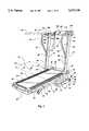
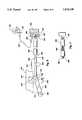
- FIG. 1is a perspective illustration of a reorienting treadmill of the present invention with the tread base positioned in a first position for a user to perform exercises;
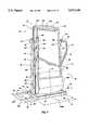
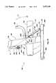
- FIG. 2is a perspective illustration of a reorienting treadmill of FIG. 1 with the tread base reoriented to a second or storage position;
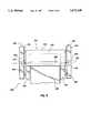
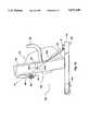
- FIG. 3is a partial, simplified plan view of a portion of a alternate configuration of a reorienting treadmill of the present invention
- FIG. 4is a partial view of portions of the reorienting treadmill of FIG. 1 and FIG. 2;
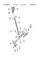
- FIG. 5is a partial perspective exploded view of an inclination assembly for use with the treadmill of the present invention to vary the inclination of the treadmill base relative to the support surface;
- FIG. 6is a partial schematic side view of an inclination assembly for use with a reorienting treadmill of the present invention
- FIG. 7shows a portion of an inclination structure for use with a reorienting treadmill of the present invention
- FIG. 8is a partial perspective of a portion of a reorienting treadmill including a latching structure associated therewith;
- FIG. 9is a partial cross sectional view of a latching structure of the type shown in FIG. 8;
- FIG. 10is a partial side view of a reorienting treadmill of the present invention with the tread base oriented in a second or stored position and with the treadmill shown in phantom oriented for movement;
- FIG. 11is a perspective view of an alternate embodiment of a reorienting treadmill of the present invention with movable handles and with the tread base oriented in a first position to receive a user for performing exercises;
- FIG. 12is a simplified partial side view of an alternate reorienting treadmill of the present invention having lift assist means and with a tread base in a first position;
- FIG. 13is a simplified partial side view of the reorienting treadmill of FIG. 12 with a tread base in a second or stored position;
- FIG. 14is a simplified partial side view of an alternate reorienting treadmill of the present invention having elevation structure associated with the tread base in its first position;
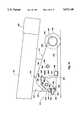
- FIG. 15is a simplified side view of the alternate reorienting treadmill of FIG. 14 with alternate elevation structure.
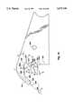
- FIG. 16is a simplified side view of portions of the alternate elevation structure of FIG. 15.
- a reorienting treadmill 10is shown in FIG. 1 to have a tread base 12 which is movably connected to support structure 14.
- the tread base 12has a left side 16 and a right side 18. As can be seen, the left side 16 and the right side 18 are spaced apart and in general alignment.
- the tread basealso has a front end member 20 and a rear end member 22. As here shown, the front end member 20 and the rear end member 22 are each cross members that form part of the overall frame of the tread base 12. That is, the frame may be said to include the front end member 20, the rear end member 22, the left side 16 and the right side 18.
- the framemay also include other structural members.
- front end member 20 and the rear end member 22denote specific structural members. However, in some contexts the front end and rear end may refer to the region or area proximate the front or the rear of the tread base 12.
- the tread base 12has an endless belt 24 positioned between the left side 16 and the right side 18.
- the endless belt 24 or treadis configured to receive a user thereon to perform exercises such as running walking, jogging or the like.
- the useralso may perform stationary exercises such as bending, stretching or the like while positioned on the endless belt 24.
- the machineprincipally is intended for use in performing walking, running or jogging exercise.
- the tread base 12 as here shown in FIG. 1,has a left side rail 26 positioned over the top of the left side and a right side rail 28 positioned over the top of the right side 18.
- the left side raft 26 and the right side rail 28are configured and positioned to support a user. That is, a user seeking to dismount from the moving endless belt 24 or tread may simply place the user's left foot on the left rail 26 and the user's right foot on the right rail 28 to dismount or leave the moving surface to terminate the exercise before terminating movement of the endless belt 24.
- the tread base 12has a front cover 30 positioned over structure such as pulley 144 associated with the drive mechanism for driving the front roller 252 not illustrated in FIG. 1, but illustrated and discussed more fully hereinafter with respect to FIG. 4.
- the front cover 30is also provided for aesthetics and for safety to minimize the risk of materials entering into the area thereunder and interfering with operation of mechanism or otherwise becoming entangled therewith.
- the tread base 12 of FIG. 1also includes an underside rigid surface 32 or pan secured to the left side 16, the right side 18, the front end member 20 and the rear end member 22 as more fully discussed hereinafter.
- the tread base 12also has rear feet means for positioning and supporting the tread base on the support surface.
- the rear feet meansinclude specifically a left foot 160 (FIG. 4) and a right foot 34 which is rotatably secured to the right side to rotate about a pin 36. That is, the right foot 34 and the left foot 160 rotate about pin 36 and pin 161 (FIG. 4), to move toward and away from the endless belt 24 to, in turn, vary the inclination of the tread base 12 relative to the support surface.
- the support structure 14 of the reorienting treadmill 10 of FIG. 1has feet means 38.
- the support structure 14 as shownis configured to be free-standing and to stably support the treadmill and more specifically the tread base 12 in the first orientation of the tread base 12 as shown in FIG. 1 and in the second or storage orientation of the tread base as shown in FIG. 2.
- the feet means 38includes a left foot 60 (FIG. 2) and a right foot 40.
- the support structure 14also includes an upright structure 42 to extend upwardly from the feet means 38. More specifically, the upright structure includes a left upright member 44 and a right upright member 46 spaced from the left upright member and in general alignment therewith.
- the tread base 12has a front portion 48 that extends 49 from the front end member 20 to a position or point 50 about midway between the front end member 20 and the rear end member 22. It may be noted that the midway point 50 is here shown to be at a distance halfway between the front end member 20 and the rear end member 22. However, those skilled in art will recognize that the actual midpoint or midway position 50 need only be approximate and is here defined to indicate that the front portion 48 is essentially that half of the tread base 12 which may be said to be frontward or forward of a similar half portion which may be said to be rearward.
- the front portion 48 of the tread base 12is rotatably attached to the support structure 14 to rotate around a base axis 52.
- the tread base 12rotates with or around bolts or pins 54 and 56 which function as an axle and are connected to the right upright 46 and the left upright 44.
- the pins 54 and 56connect to pivoting straps 55 and 57 which are attached to their respective right and left sides 18 and 16 to extend upwardly therefrom. With the straps 55 and 57 extending upwardly, the base axis 52 may be located above the tread base 12 when the tread base is in the first position as shown in FIG. 1.
- the length or height of the straps 55 and 57 and the orientation to extend upwardly from the sides 16 and 18 or downwardly from the sides 16 and 18may be selected to position the center of gravity of the tread base 12 relative to the base axis 52. That is, the necessary force or leverage to lift and move the tread base 12 from the first position to the second position may be varied by varying the distance between the center of gravity and the base axis 52 as discussed more fully hereinafter.
- the support structure 14 and more particularly the feet means 38is shown to include a forward cross member 58 which is connected to the right foot 40 to extend to the left foot 60.
- the foot means 38includes a rear cross support 62 that extends between and is connected by nuts and bolts 61 and 63 to brackets 65 and 67 to the right foot 40 and the left foot 60 spaced rearward 62 from the front cross member 58 a distance 63 selected to rigidly support the right foot 40 and left foot 60.
- the cross members 58 and 62also may be connected by welding, brazing or the like as desired.
- the right foot 40 and left foot 60are each sized in length and spaced apart a distance 67 to provide the support structure 14 with a footprint so that the support structure is freestanding and also stably supports the tread deck 12 in the first position, in the second position and in movement thereinbetween.
- the footprintmay be regarded as the perimeter of the geometric figure projected on the support surface that is defined by left foot 60 and right foot 40.
- the footprintcould be in any desired geometric shape to have a length 65 and width 67.
- the length 65 and width 67are selected so that the distance 69 between the vertical location of the center of gravity 71 (projected onto the support surface) of entire treadmill 10 is selected so that the force necessary to tip the treadmill 10 is necessarily more or higher than that applied by a nudge or accidental bump.
- the feet 40 and 60extend a similar distance 73 selected so that the tipping force F 1 necessary to cause rotation or tip of the treadmill exceeds a nominal sum (e.g., 1 pound) and indeed is at least a somewhat larger sum (e.g., 10 to 20 lbs.) and even more preferably a significantly larger sum.
- the distance 73preferably is selected so that tipping can be effected only by a user deliberately seeking to rotate or tip the treadmill 10 in normal use.
- the distance 67 of the treadmill 10is selected so that the distance 75 between the center of gravity 71 and the feet 40 and 60 will resist accidental tipping by a bump or nudge. That is, the treadmill 10 cannot be tipped over sideways except upon application of a force F 2 that exceeds a nominal sum (e.g., 1 pound) and is about the same as force as F 1 .
- a force F 2that exceeds a nominal sum (e.g., 1 pound) and is about the same as force as F 1 .
- the right foot 40has a right wheel 64 rotatably positioned at its forward end 68 to rotate about an axle 66. At the forward end 68, the right foot 40 angles rearwardly 77 toward a lower edge 70 thereby exposing the wheel 64 to facilitate rotation of the support structure 14 onto the wheel 64 for movement of the treadmill 10 on the support surface.
- the left foot 60(FIG. 2) has a left wheel 72 positioned to rotate about an axle 74.
- the left wheel 72is exposed to facilitate rotation and movement inasmuch as the left foot 60 is formed to have a front portion 76 that angulates rearward and downward 74 towards the lower edge 76 of the left foot 60.
- the left foot 60 and the right foot 40are both made of a rectangular (incross section) hollow tube to contain the wheels 72 and 64. Therefore the support structure 14 can be tipped or rotated onto the left wheel 72 and right wheel 64.
- the support structurehas associated therewith a pair of rigid non-movable handles.
- the left rigid non-movable handle 80includes a first portion 82 that is connected to the left upright 44 near its upper or distal end 81.
- the first portion 82extends rearwardly to a second portion 84 that extends downwardly towards the foot means 38.
- a third portion 86is interconnected to the second portion to extend inwardly toward the upright 44 and is here preferably shown to be rigidly secured such as by welding 88 to the left upright 44.
- the right rigid non-movable handle 90is here shown to include a first portion 92 that is connected at the upper end 91 of the upright 46 to extend rearward from the right upright member 46.
- a second portion 94is shown connected to the first portion 92 to extend downwardly toward the foot means 38.
- a third portion 96extends from the second portion inwardly toward the right upright member 46 and is here shown to be secured such as by welding 98 to the right upright 46.
- the pair of rigid non-movable handles 80define a space 100 therein between. That space 100 may be said to create a cage-like effect because the rigid handles 90 and 80 extend rearwardly (toward the rear end member 22) when the tread deck 12 is oriented in the first position shown in FIG. 1.
- the space 100is here oriented over the forward part of the endless belt 24.
- the length 83 of the upper portions 82 and 92 of the handles 80 and 90may be selected to increase or decrease the size of the space 100 and more particularly the volume.
- a user positioned at or proximate the mid point 50 on the endless belt 24may perceive the handles 80 and 90 as near the user's hands for easy grasping to maintain balance when on the endless belt 24 and perceive the space 100 as a cage-like area toward which the user may move; and in turn the user may feel more stable or secure.
- the exercise treadmill 10 of the present inventionhas a control console 102 which is connected to a support bar 104 that is attached to and extends between the left upright 44 and the right upright 46.
- the console 102has operating controls such as actuator 106 to operate the treadmill 10 and indication means which may be used by the operator to determine various parameters associated with the exercise being performed.
- the console 102may also have a cup or glass holder 108 so that the user may position a liquid refreshment for use during the course of performing exercise.
- the treadmill of FIG. 1also includes a latching structure and more particularly a receiving mechanism 110, which is more fully discussed hereinafter.
- left rigid non-movable handle 80is fastened to the left upright 44 at its upper end 81 by a mechanical clamping structure 368 to be discussed more fully hereinafter.
- right rigid non-movable handle 90is similarly attached by a clamping structure 114 is more fully discussed hereinafter.
- the control console 102 of FIG. 1also has associated therewith a safety lock or key mechanism 116 with a loop structure 118 associated therewith for attachment about the waist or to the user.
- the safety lock or key structure 116is configured so that if a user moves toward the rear end member 22 on the endless belt 24, a key (not shown) is removed from the control console thereby interrupting the electrical power to the motor driving the endless belt for a motorized treadmill.
- the reorienting treadmillis shown with the tread base 12 reoriented relative to the support structure 14 to the second position in which the rear end member 22 of the tread base 12 is positioned towards the upright structure 42 of the support structure 14.
- the treadmill 10is significantly more compact, occupying less floor space of the associated support surface.
- the tread base 12, the left side 16 and the right side 18are here formed to present relatively flat mating surfaces.
- the front end member 20 and rear end member 22each present a flat surface to receive a portion of the perimeter 122 of the pan or rigid surface 32. That is, the flat surface portion 124 of the left side, the flat surface portion 126 of the rear end member 22, the flat surface portion 128 of the right side 18 and the flat surface portion 130 of the front end member 20 are desirably formed to be in substantially the same plane to present a substantially flat surface to mate and register with the flat surface 132 formed along the perimeter 122 of the rigid surface 32.
- the rigid surface 32is here shown to be unitarily formed of a plastic-like material to present an essentially rigid underside 120. Although rigid, it may be made of material thin enough to be flexible or to deflect without breaking.
- the rigid surface 32here has a recess 134 formed in it proximate the rear end 22 to provide a convenient hand position for the user to move or reorient the tread deck 12 from the first position or exercise position shown in FIG. 1 to the second position or storage position shown in FIG. 2.
- rigid surface 32has a housing portion 136 formed proximate the front end member 20 to cover operating structure such as the motor 138, the flywheel 140, and the driving belt 148.
- the housing 136also covers the electrical motor controlling mechanism 150, as well as the mechanism necessary to operate the inclination structure as more fully discussed hereinafter.
- the underside 120 of the tread base 12is here shown with the pan or rigid surface 32 in position.
- the tread base 12 without the pan or rigid surface 32leaves operating structure such as the motor 138, electrical components 150 and the inclination system 152 exposed (FIG. 4).
- the exposed componentscan be hazardous providing sharp edges, points and structure against which items or things may bump or snag.
- electrical componentsthere is a risk of exposing electrical components to moisture, as well as exposing the user to an electrical shock hazard if the treadmill is inadvertently not turned off.
- the rigid surface 32may be formed to cover only a portion of the exposed components or may be formed into multiple removable sections, if desired, to facilitate assembly or repair.
- the flat surfaces 126, 128, 130 and 124have a plurality of apertures 154 formed therein to receive screws 156 to secure the rigid surface 32 or pan to form the underside of the tread base 12.
- the rigid surface 32has an aperture 158 formed therein for the left leg 160 to extend therethrough.
- a similar aperture 162is formed to pass the right leg 34 therethrough.
- the right leg 34has a wheel 164 appended proximate its distal end 166.
- the left leg 160has a wheel 168 appended proximate its distal end 170.
- the wheels 164 and 168are rotatably attached to facilitate movement on a support surface when the tread base 12 is positioned in the first position. Other guides, skids or the like may be used to facilitate movement of both the legs 134 and 160 on the support surface.
- FIG. 3an alternate configuration of a reorienting treadmill is shown, which is similar to the reorienting treadmill shown in FIGS. 1 and 2.
- a reorienting treadmill 200has a right foot 204 and a left foot 202. It also has a right upright 208 and a left upright 210 attached to and extending upward from the right foot 204 and a left foot 202.
- a tread base 216has a front end 218 with a protective cap 220 positioned as shown.
- the tread base 216has a left side 222 and a right side 224 with an endless belt 226 positioned between to receive a user comparable to the endless belt 24 in FIG. 1.
- a front roller 228is positioned to extend between the left side 222 and the right side 224.
- the front roller 228has an axis 230 with an axle 232 extending therethrough to rotate about axis 230.
- the front roller 228extends into the right upright 206 and the left upright 210 to function as a base axis similar to base axis 52.
- the right foot 204has a wheel 234 rotatably mounted by axle 236 within the right foot 204.
- the left foot 202has a left wheel 238 rotatably positioned within the left foot 202 by an axle 240.
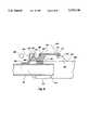
- FIG. 4shows a portion of the treadmill 10 of FIGS. 1 and 2.
- the treadmill 10 of FIGS. 1 and 2is preferably a motor driven treadmill having a controller 150 interconnected by conductors 250 to motor 138.
- the motorrotates to operate a pulley 146, as well as a flywheel 140.
- the pulley 146drives a belt 148 which, in turn, drives a pulley 144 connected to the front or drive pulley 252 about which the endless belt 256 is trained.
- the front roller or drive pulley 252is connected to the right side 18 by a bushing 258.
- the pulley 252is similarly connected to the left side 16 by a bushing 260.
- the motor 138 and the controller 150are positioned between the front end member 20 and the rotation or base axis 52 to, in turn, position their mass or weight and control the location of the center of gravity. That is, the weight of the motor and the electrical components 150 create a cantilever effect because the mass thereof is displaced toward the front end member 20 a distance 262 to act as a counter balance upon rotation of the tread deck 12 from the first position shown in FIG. 1 to the second position shown in FIG. 2, as well as here in FIG. 4.
- a cross support 264is interconnected such as by welding between the left side 16 and the right side 18 in order to receive the incline mechanism 152. That is, an incline mechanism 152 shown here in FIG. 4, as well as in the exploded view of FIG. 5, includes a motor 264 interconnected through a reduction gear mechanism 266 and pinion 270 to a rack 268. Operation of motor 264 causes the pinion 270 to drive the rack 268 forward and rearward 272 to, in turn, drive an extension 274.
- the rack 268is connected to the extension 274 by a pin 276 or any other acceptable mechanical means.
- the motor 264 and the reduction gear 266are connected by a metal or rigid strap 278 to a bracket 280.
- the strap 278has an aperture formed therein to receive a pin 282.
- Spacer 284maintains the strap 278 in alignment.
- the motor 264 with reduction gear 266is pivotally connected to the cross member 264.
- the motor 264is electrically controlled via conductors 286 from the controller 150 which, in turn, receives control signals from the control panel 102.
- the extension 274is here rotatably connected by a pin 288 to a cantilever 290 that is secured such as by welding to a cross member 292.
- the cross member 292is connected to extend between and to be secured such as by welding to the right foot 34 and the left foot 160.
- the rack 268is connected by a pin 276 which is here secured by a threaded nut 294 or by a compression nut (not here shown).
- the extension 274is rotatably connected by pin 288 to the cantilever 290 by a pin 288 held in place by a cotter pin 296.
- the right leg 34has wheel 164 secured thereto by a bolt 298 secured in place by nut 300.
- the left leg 166has a left wheel 168 secured thereto by bolt 302 and nut 304.
- FIG. 6An alternate configuration of an inclination system is shown in FIG. 6.
- a leg 306 with a wheel 308 appended at its distal end 310is rotatably secured to a side 312 of a tread base to rotate about an axle 314.
- a cantilever 320is secured such as by welding to the cross member 318.
- An extension 322is rotatably attached to the cantilever to rotate about a bolt or pin 324.
- the extension 322is connected at its proximal end 324 by a pin or nut and bolt 326 to a pneumatic spring 328.
- the pneumatic spring 328contains gas under pressure, a chamber and a movable piston.
- the pneumatic spring 328is operable by operation means which here includes an actuation means. More specifically, the operation means includes a cable 330 within a sheath 332.
- the cable 330is connected to actuation means such as actuator 333 for operation by a user positioned on the endless belt of the tread deck when the tread deck is positioned in the first position for use in performing exercises. Movement of the actuator 333 causes the cable to move, in turn, operating the lever 334 to contact a pin 336 associated with the pneumatic cylinder 328.
- Compression of the pin 336operates the cylinder to cause the piston rod 338 to extend or retract to thereby move rearward 340 or forward thereby causing the cantilever 320 to rotate clockwise 342 and, in turn, cause the cross member 318 to rotate 319 clockwise (increase inclination) or counter clockwise (to decrease inclination) as here shown in FIG. 6.
- Rotation of the shaft 318 clockwise 342causes the foot 306 to rotate relative to the side 312 and, in turn, the endless belt to in turn vary the inclination of the side 312 and the endless belt relative to the support surface.
- the usermay move his weight rearward on the endless belt. That is, the user may move (such as in FIG. 1) from the forward portion of the tread base towards the rear portion of the tread base to, in turn, vary the lever arm and increase the force downward on the foot 306 to, in turn, urge the shaft 322 inward or outward and, in turn, cause the inclination to increase or decrease.
- the force of the user moving rearward on the front deckis sufficient to overcome and exceed the force being exerted by the pneumatic cylinder 328.
- the pneumatic spring 328is secured to a bracket 345 that is rotatably attached by a pin 344 to a cross member 346 which is secured to and in between the opposite sides of a tread base (not here shown) such as side 312.
- a coil spring 350is positioned within a cylindrical housing 352 shown in cutaway.
- the cylindrical housing 352is rotatably attached to rotate about a pin 354 at one end.
- the cylindrical housing 352also has an extension 356 with an aperture 358 for rotatable connection to an extension such as extension 324.
- the spring mechanism of FIG. 7may be used to vary the inclination of the endless belt of the tread base by the user varying the rotation of associated feet, such as foot 306.
- the footmay be pinned by positioning a pin or bolt through an aperture passing through one or both sides of the tread base, such as side 312, and one of a plurality of apertures formed in the foot such as foot 306.
- the usermay use his hand or his foot to apply downward pressure to the tread base in order to vary the inclination to overcome the force of the spring 350.
- the latching mechanism 110is here shown in an exploded view in association with the left upright member 44 of the support structure 42.
- the upward or distal end 360 of the upright 44reveals that the upright 44 is, in fact, a hollow rectangular channel.
- One surface 362 of the upright 44is formed with an arcuate recess 364 formed to receive the circular in cross section left non-movable rigid handle 80 and more particularly the first portion 82 of the left non-movable handle.
- the inner end 366 of the first portion 82is positioned within the hollow portion of the upright 44 as shown.
- a top clamp 368is sized and configured to snugly fit over the distal end 360 of the upright 44.
- the top clamp 368has apertures 370 formed in one side 372. Similar apertures 374 are formed in the opposite side 376 (FIG.9).
- Associated screws 378 and 380pass through the apertures 370 and 374 to register with corresponding apertures formed in the upright 44 to secure the top clamp and the inner end 366 thereto.
- the clamping structure 368has a semi-circular portion 384 formed to register with the first portion 82 of the left rigid handle structure to snugly hold the first portion 82 of the left rigid handle structure 80 in place and to resist or inhibit outward 386 movement of the first portion 82 of the left rigid handle structure.
- top clamp 368securely receives the support bar 104 into an appropriately sized aperture 388.
- the support bar 104is sized in cross section to snugly and slidably insert into the aperture 388.
- a base 390is shown secured or fastened to the cross member 104.
- the base 390is fastened by either welding, gluing, brazing or similar means as desired.
- the control console 102is fastened to the base 390.
- the treadmill 10 of the present inventionmay include latching means adapted to the tread base 12 and to the upright structure 42.
- the latching meansis operable for releasably attaching the tread base 12 in the second position to the upright structure 42.
- the latching meansincludes a receiving mechanism 391 which is configured to receive a latch member 392 such as latch bar 393 (FIG. 4).
- the latch member 392is configured to removably connect to the receiving mechanism 391.
- the receiving mechanism 391is attached to the top clamp 368 which functions as a housing.
- the top clamp 368is positioned at the distal end 360 of the left upright 44.
- the latch member 392is shown in FIG. 4 to be a cylindrically shaped bar 393 that extends outwardly and normally from the left side 16. As the tread base 12 is rotated upwardly from the first position towards the second or storage position, the latch member 392 moves inwardly 394 towards the cam surface 396 of lever member 398. As here seen, the lever member 398 is rotatably attached to the top clamp 368 within a housing 399 to rotate about a pin 400 that functions like an axle. The lever member 398 rotates between a first position, as shown in FIG. 9, and a second position in which the lever member 398 is rotated counterclockwise 402.
- the spring meansmay be any form of acceptable spring, including a coil spring, a leaf spring or even a clock spring associated with the pin 400.
- the spring as here shownis a block of an elastically deformable polyurethane sponge 406 or any other rubber-like or elastically compressible substance.
- any acceptable springmay be used to urge the lever member 398 from a displaced or second position to the at rest or first position as shown in FIG. 9.
- the lever member 398has a lower surface 408 configured to act against the spring 406 to compress it upon counterclockwise rotation 402.
- Counterclockwise rotation 402can also be affected by grasping the handle means 410 formed at a distal end 412.
- the handle meanis formed by shaping the distal end 412 to provide a space 414 between the distal end 412 and the upper surface 416 of the top clamp 368 so the user may place one's finger about the distal end 412 and more particular, about the handle 410 in order to urge it in a counterclockwise direction 402 out of the housing 399. Therefore, the lever member 398 may be manually rotated so that the latch member 392 may be moved from the receiving portion 418.
- the receiving portion 418is a cylindrically shaped recess sized and shaped to receive the cylindrically shaped latch member 393.
- the tread base 12may be moved from the first position as shown in FIG. 1 to the second position or storage position shown in FIG. 2.
- the latch member 393is urged against the cam surface 396 as hereinbefore stated.
- the usermay grasp the left rigid handle structure 80, the right rigid handle structure 90, or both, while pushing on the rear end 22 or the rigid surface 32 to urge the tread base 12 and, in turn, the latch member 392 into the receiving portion 418.
- the spring means or 406may operate to urge the lever member 398 from a displaced position (not shown) to the first position as shown in FIG. 9.
- a receiving portion 418may be used in order to facilitate an automatic latching arrangement of the type herein described.
- the lever member 398may be configured in a variety of shapes in order to permit displacement by a latch member on a cam surface following which the latch member enters a space or area provided to inhibit movement of the latch member from that space.
- lever member 398may be positioned either on the distal end 360 of the left upright 44 or similarly on the distal end 91 of the right upright 46.
- lever 398 with a housingmay be positioned on the tread base 12 to intersect with a latch member associated with the left upright 44 or right upright 46, as desired.
- FIG. 10a simplified representation of a reorienting treadmill 420 is shown similar to the treadmill 10 shown in FIG. 1.
- the treadmill 420is shown from the side view with a right upright 422 connected to a right foot 424 at an angle 426 here shown to be about 15°.
- the angle 426may be from about zero to about 25°.
- the angle 426is selected in order to position the center of gravity 446 of tread base 434, as well as the center of gravity of the overall treadmill 458, as more fully discussed hereinafter.
- the illustrated treadmillhas a control panel 428 connected to a cross support 430 which extends between the right upright 422 and the left upright (not shown).
- the treadmill 420also has a right rigid handle structure 432 connected to the right upright 422. It also similarly has a left rigid handle structure connected to the left upright (not here shown).
- the tread base 434has a rear end 436 which extends upwardly as shown when the tread base 434 is positioned in the second or storage position as shown in FIG. 10.
- the tread base 436is rotatably connected to rotate about a base axis 438.
- the center of gravity 440 of the tread base 434is positioned to be spaced upwardly 444 from the base axis 438. That is, from FIG. 4 it can be seen that the tread base 12 (FIG. 1) and similarly the tread base 434 have mass.
- Various componentssuch as the motor 138 and electronics 150 (FIG. 4) are positioned so that the center of gravity 440 of the tread base 434 is above base axis or axis of rotation 438.
- the center of gravity 440passes through vertical alignment 446 with the axis of rotation.
- the tread base 434is rotated until the center of gravity 440 is displaced clockwise past the vertical 446 a distance 448 selected to stably retain the tread base 434 in the second position with or without a latching means as hereinbefore discussed. That is, the location of the center of gravity 440 of the tread base 434 clockwise past the vertical 446 creates a lever arm to hold the tread base 434 in the second or stored position as shown.
- the center of gravity 440is selected to be displaced above the axis of rotation 438 at a preselected distance 444.
- the distance 444is selected so that the weight or mass of the tread base 434 when acting downwardly at the center of gravity 440 is displaced toward the axis of rotation 438 to minimize the amount of upward or lifting force needed at the rear end 436 to lift the tread base 434 and move it from the first position toward and into the second position.
- the location of the center of gravity 440may vary based on the size, weight, construction and shape of each individual model of treadmill.
- the center of gravity 440 and more particularly the location of the center of gravity 440is selected so that the total mount of lifting force necessary to lift the rear end 436 when the tread base 434 is in the first position is such that a normal user may be able to easily lift and rotate the tread base from the rust position to the second position.
- the foot 424has an angulated forward surface 450.
- the wheel 452 positioned in the front or forward end 454 of the right foot 424is positioned to rotate about an axle 456.
- the wheel 452is positioned so that it does not contact the support surface until the upright or support structure 422 is rotated or displaced from a first or standing position to a displaced position here shown phantom as 420 with the upright identified as 422'.
- the center of gravity 458 of the entire treadmill 420is determined by the weight and mass of all of the components of the treadmill 420 and may be the same as or displaced from the center of gravity 440 of the tread base 434.
- the center of gravity 458 of the entire treadmill 420is desirably positioned at a height or distance 460 which may be above or below the center of rotation 438 but nonetheless close to the center of rotation 438. However, it must be placed above the foot 424 in order to facilitate rotation of the treadmill 420 from the configuration and position shown in solid in FIG. 10 to that shown in phantom in FIG. 10.
- the center of gravity 458is rotatable to a position 458' to be generally positioned over the axle 456 of the wheel 452 to minimize the downward force or the lifting force necessary to be exerted by the user when holding the treadmill 420 in the position shown in phantom in FIG. 10.
- the position shown in phantom in FIG. 10is the position for moving or pushing the treadmill 420 about the support surface from one location to another.
- the treadmill of FIG. 10is formed to have a left handle and a right handle available for grasping by the user to facilitate holding and moving the treadmill 420 when in the position shown in phantom in FIG. 10.
- the left handle and the right handlemay be any structural component readily available for grasping by the user, while the user is moving the treadmill 420 when the treadmill 420 is in the orientation shown in phantom in FIG. 10. More particularly, the rigid handle structure 432 on both the left and the right side may be grasped by the user potentially along the first portion such as the first portion 92 and 82 of the rigid handles shown in FIG. 2 and in FIG. 1.
- the usermay be able to grasp and hold a portion of the support bar 430 in order to hold on to and urge or move the treadmill 420 when supported on the right wheel 452, as well as the corresponding left wheel (not here shown).
- a portion of the top clamp 368 as well as the bracket 114 shown in FIG. 4extends outwardly or over the respective distal ends 81 and 91 of the upright supports 44 and 46. That is, the clamp 460 shown in FIG. 10 and the clamp on the left side (not shown) may be grasped by the user to support and hold the treadmill 420 for movement about the support surface while supported by the wheel 452 on the right side, as well as a wheel similarly positioned on the left side.
- an alternate configuration of the treadmill 470has a tread base 472 comparable to tread base 12 in FIGS. 1 and 2. Similarly, it has support structure 474 including a left upright 476 and a right upright 478. It also has left rigid handle structure 480 and right rigid handle structure 482. As also shown, the treadmill 470 has a movable left handle 484 which is rotatably attached to the left upright 476 with a hand-operated knob 478 useful to tighten or secure the handle 485 and increase resistance or decrease resistance to rotation. As can be seen, the handle 484 has a gripping portion 486 configured for grasping by a user. A right handle 490 is here shown to be pivotally attached at an axis 488 to rotate thereabout. The right handle 490 also has a grip portion 492 positioned for grasping or movement by a user in a back and forth 480 or pivotal movement when the user is positioned on the endless belt 494.
- the tread base 12has a deck 500 which extends between and is connected to the left side 16 and the right side 18.
- the tread deck 500may be formed of any acceptable rigid material which may be acceptable plywood materials with a wax or slippery upper surface over which the endless belt 24 is trained and moves.
- the tread deck 12 of FIG. 4has a rear pulley 502 connected to extend between the left side and the right side.
- the rear pulley 502is adjustably positioned and movable forwardly and rearwardly by a bolt structure 504 on the left side.
- a bolt structure 506 with an associated spring 508is provided to provide movable or adjustable tension to the rear pulley 502 so that in use, the endless belt remains centered on the front pulley 252 and the rear pulley 502.
- guides 510 and 512may be secured to the deck 500 to extend away therefrom. The return portion 513 of the endless belt 24 may ride against the guides 510 and 512 to further facilitate centering of the endless belt 24 on the roller 252 and rear roller 502.
- the tread base 12has a length 514 which is here selected to facilitate performance of walking, jogging or running exercises as desired. That is, the length 514 may vary for treadmills configured for walking and treadmills configured for jogging and running. In turn, the length of the tread 24 itself will vary as desired.
- the usermust first move the tread base 12 from the upright or the stored position shown in FIG. 2 and 4, to the first or operating position shown in FIG. 1.
- the userstands on the endless belt 24 and walks, jogs or runs to perform exercises.
- the usermay operate the switch on the control panel 102 to electrically operate the electrical auto-incline system shown in FIGS. 5 and 4.
- the usermay operate or manipulate an actuation member to, in turn, actuate a pneumatic cylinder of an inclination system such as that shown in FIG. 6 and move his or her weight back and forth on the endless belt to vary the downward movement and control inclination.
- control panel 102Upon selection of the desired inclination, the user may, thereafter, operate control panel 102 through the use of safety switches and operating switches to energize the motor, such as motor 138 to, in turn, power the tread while performing exercises.
- the userIn order to operate the treadmill in an electric configuration, the user must obviously provide energy to the system by inserting the plug 516 (FIG. 4) into a conveniently available wall outlet.
- the reorienting treadmill 500is similar to the treadmill of FIGS. 1, 2 and 4. It has support structure 502 with a tread base 504.
- the support structure 502has a left foot 506 and a comparable spaced apart right foot (not shown) with interconnecting cross supports (not shown) to define a footprint similar to the footprint for the treadmill of FIGS. 1 and 2.
- the support structure 502also has a left upright 508 and a spaced apart right upright (not shown), each secured to the respective left foot 506 and right foot by any means to provide a secure connection. Welding, bolts or the like are contemplated as acceptable means.
- the tread base 504is rotatably attached to and between the left upright 508 and the right upright such as by bolts 510 or other similar pins, bars or the like to function as an axel.
- the tread base 504is rotatable between a first position 512, seen in FIG. 12, and a second or stored position 514, seen in FIG. 13.
- the tread base 504rotates about the bolts 510.
- the amount of lifting force (LF) necessary to rotate the tread base 504 upward or counterclockwise (as shown) from the first position 512 toward the second position 514may be large enough so that rotation is difficult.
- componentssuch as an inertia wheel or motor may be located forwardly 516 and, more specifically, forward 516 of the bolts 510.
- the weight of such components and the related portion of the tread base 504 forward 516 of the bolts 510will act as a counterbalance to reduce the lifting force (LF) required to reorient the tread base 504 between the first 512 and second 514 positions.
- LFlifting force
- a lift assistance assemblyis also provided to apply a force or torque urging the tread base 504 from the first position 512 toward the second position 514.
- a gas cylinder 505is rotatably attached at one end to bracket 503 secured to the tread base 504. That is, the piston rod 505A has a bushing 505B that is attached by a pin or bolt 505C.
- the gas cylinder 505is attached to bracket 501 which is itself attached to the left foot 506 or a cross member 506 (not shown) extending between the left foot 506 and the right foot. Alternatively, the gas cylinder may be attached to the right foot and the right side of the tread base 504 (not shown).
- the gas cylinder 505has a bushing 505D held to the bracket 501 by a pin or bolt 505E.
- the gas cylinder 505applies a torque force (TF) in the direction illustrated.
- the torque force (TF)is spaced from the axel bolts 510 a distance D that may be varied to increase the leverage and in turn the torque in foot-pounds. That is, gravitational forces (GF) are exerted on the mass of the tread base 504 to develop a torque causing the tread base 504 to rotate toward the first position.
- the force and the torque (TF) exerted by the cylinder 505is selected so that the resulting required lifting force (LF) may be nominal (e.g. 5 to 20 pounds).
- FIGS. 12 and 13also show the left foot 506 with a plurality of floor supports 499A and 499B attached thereto and extending therebelow for contact with the support surface.
- the floor supports 499A and 499Bare preferably made of a material that may have a high coefficient of friction to avoid sliding or walking of the machine on the support surface.
- the floor supports 499A and 499Bare also sufficiently soft to reduce the risk of scratching or marring a support surface such as wood or tile.
- a pivotal handle 498is also shown rotatably attached by a bracket 497 fixedly secured to the upright 508 by bolts 497A and 497B.
- a resistance knob 496is also shown that is operable by the user to vary the resistance to movement of the handle 498.
- a fixed handle 495is also shown in FIGS. 12 and 13.
- FIG. 14an alternative form of reorienting treadmill 590 is shown. It has a tread base 592 that is reorientable 593 from a first position 594 to a second position similar to the treadmills of FIGS. 1 and 2.
- the tread base 592rotates 593 about bolts 596 which are attached to left upright 598 and right upright (not shown).
- the left upright 598 and the right upright (not shown)are each attached to a respective left foot support 600 and a right foot support (not shown).
- a pair of spaced apart supportsare attached to support the tread base on a support surface.
- the left and right supportseach have a leg 604 that is snugly and slidably movable in a housing 606.
- the leg 604has a plurality of apertures 608 which can be placed in registration with an aperture 610 in both sides of the housing.
- a pin 612is insertable through the apertures 610 and 608 to position the leg 604 at a selected distance from the tread base 592 and to, in turn, vary the inclination of the tread base 592 relative to the support surface.
- the treadmill 590 of FIG. 14is shown with a flywheel housing 614 at its front end.
- the flywheelis connected to the endless belt (not shown) and receives energy from the user operating the endless belt of the tread base 592. It also delivers energy to that endless belt as the user performs walking, running or jogging exercise when the user is suspended and not in contact with the endless belt.
- FIGS. 15 and 16an alternate elevation system 511 is shown attached proximate the rear 602 of tread base 592.
- the elevation systemmay have two spaced apart assemblies comparable to the assembly 513 shown.
- the assembly 513has a generally rectangular planar member 519 which is secured to the tread base 592 in a generally vertical orientation.
- the planar member 519may be fabricated of metal and secured to the metal frame of the treadmill by bolts, welding or the like.
- the assembly 513has a support 515 that is an elongate planar member having a first end 514 and a second end 516.
- the first end 514is shaped to be an elongate finger-like extension which functions as a stop for the pawl 518.
- the support 512further has a ratchet section having a plurality of recesses or notches 520 along its perimeter.
- three distinct notches 520A, 520B and 520Care formed in the perimeter 521. In other configurations, 2 or 4 or more notches may be present.
- the first notch 520Asubstantially corresponds to the perimeter of a section of the pawl 518 whereby the pawl 518 may be surrounded on a plurality of its sides when that pawl 518 is inserted into the first notch 520A.
- the second notch 520Bis defined by the sides 528 and 530 of the perimeter 521 of the support 515.
- the third notch 520Cis defined by the sides 532 and 534 of the support 515.
- the extension 536may be viewed as being substantially a rectangularly configured section having a longitudinal axis 538 which is oriented to a horizontal axis 539 at an angle A. Given the essentially rectangular configuration of extension 536 it should be understood that linear side 540 would also be oriented at an angle A to the horizontal. In a preferred construction, angle A may be within the range of 125 to 136 degrees and preferably 131 degrees.
- the side 522 which extends from side 540is oriented at an angle B from the horizontal.
- angle Bmay be within the range of zero to ten degrees, preferably four degrees.
- Side 524, which extends from side 522,is oriented at an angle C from the horizontal.
- Angle Cis within the range of 22 to 34 degrees and preferably approximately 28 degrees.
- Side 526 which extends from side 524is oriented at an angle D from the vertical.
- angle Dmay be within the range of 36 to 48 degrees and preferably 43 degrees.
- Side 528which extends from side 526 is oriented at an angle E from the horizontal.
- angle Eis within the range of four to 15 degrees and preferably nine degrees.
- Side 530extending from side 528, defines an angle F with the vertical.
- Angle Fis preferably within the range of 17 to 29 degrees and preferably 23 degrees.
- Side 532which extends from side 530, is oriented at an angle G from the horizontal.
- Angle Gis within the range of five to fifteen degrees and preferably ten degrees.
- Side 534which extends from side 532, is oriented vertically upright, i.e., at an angle of 90 degrees to the horizontal.
- Sides 526 and 530are dimensioned to provide sufficiently deep notches to enable the top of the pawl 518 to be received in the notches 520B and 520C and form a detachable union with each notch to retain the support in a fixed orientation relative to the exercise apparatus.
- the support 515is rotatably connected to the planar member 519 by means of a pivot axle 542.
- the pivot axle 542is an elongate cylindrical member which extends outwardly and perpendicularly from the surface 521 of the planar member 510.
- the axle 542extends through a circular aperture 544 formed in the support 515.
- the axle 542may be fixedly secured to the planar member 519 while the support 515 is rotatable about the axle 542.
- the axle 542may be fixedly secured to the support 515 and rotatably secured to the planar member 519.
- the axle 542may also be rotatably secured to the planar member 519 while the support 515 is rotatably secured to the axle 542.
- the end 516 of the support 512may be adapted to a connection bar 546 which extends between two spaced apart supports.
- the opposing ends 548 of the bar 546are fitted with end caps 550.
- the end caps 550are preferably fabricated from a material having a high coefficient of friction.
- the end caps 550rest directly on the support surface and form the point of contact between the incline adjustment mechanism and the support surface.
- the opposite supportsmay be further interconnected to one another by means of a spacer bar 552.
- the pawl 518is also a planar member having a somewhat rectangular configuration on one end 554 thereof and an angled surface 556 on its other end 558.
- the pawl 518is rotatably secured to the planar member 519 by a pivot axle 560.
- Axle 560may be configured as an elongate cylindrical shaft which is either fixedly or rotatably secured to the planar member 519 so that the pawl 518 is rotatable with respect to the planar member 519.
- a substantially V-shaped spring 562is secured at its first end 564 to the planar member 519 by means of a pin 566.
- the end 564is formed into a substantially circular configuration which in turn is wrapped around the pin 566.
- the opposing end 568 of the spring 562is also formed into a generally circular configuration which in turn is also secured about a pin 570 which is affixed to the pawl 518.
- the spring 562is constructed to exert a force in the direction of arrow 572. The spring 562 therefore urges the pawl 518, and more specifically, the surface 556 to rotate clockwise into abutment against the support 515 proximate the notches 520A, 520B and 520C of that support.
- the pawl 518is urged against the perimeter 521 of the support 515 which defines the notches. As the surface 556 of the pawl 518 is urged into one of the notches, the pawl 518 forms a detachable connection with the support 515.
- the support 515When the support 515 engages the support surface, such as a floor, the support 515 is urged to rotate in a counterclockwise direction about its pivot axle 542. Should the pawl 518 be secured in notch 520A of the support 512 counterclockwise rotation of support 515 is precluded by the pawl 518. When the end 602 of the treadmill is lifted vertically, the weight of the bar 546 and other components at the end 516 of the support 515 urges the support 515 to rotate clockwise about the axle 542.
- the spring 562is configured such that the force applied to the pawl 518 is less than the torque or force urging clockwise rotation of the support 515.
- a weight 572may be attached to the pawl 518 to urge it to rotate clockwise from notch 520A to notch 520B and 520C, but to rotate counterclockwise when the pawl 518 is urged to a more upright orientation by corner 574.
- the operation of the assembly 513is described more fully in U.S. patent application Ser. No. 539,249 filed Oct. 5, 1995, the disclosure of which is incorporated herein by reference.
- a non-motorized arrangementmay also be used in which an inertia wheel comparable to a flywheel 140 is provided to provide or deliver torque or energy to the endless belt 24 while the user is walking, jogging or running.
Landscapes
- Health & Medical Sciences (AREA)
- Cardiology (AREA)
- Vascular Medicine (AREA)
- General Health & Medical Sciences (AREA)
- Physical Education & Sports Medicine (AREA)
- Rehabilitation Tools (AREA)
Abstract
Description
Claims (38)
Priority Applications (1)
| Application Number | Priority Date | Filing Date | Title |
|---|---|---|---|
| US08/593,798US5672140A (en) | 1996-01-30 | 1996-01-30 | Reorienting treadmill with inclination mechanism |
Applications Claiming Priority (1)
| Application Number | Priority Date | Filing Date | Title |
|---|---|---|---|
| US08/593,798US5672140A (en) | 1996-01-30 | 1996-01-30 | Reorienting treadmill with inclination mechanism |
Publications (1)
| Publication Number | Publication Date |
|---|---|
| US5672140Atrue US5672140A (en) | 1997-09-30 |
Family
ID=24376231
Family Applications (1)
| Application Number | Title | Priority Date | Filing Date |
|---|---|---|---|
| US08/593,798Expired - LifetimeUS5672140A (en) | 1996-01-30 | 1996-01-30 | Reorienting treadmill with inclination mechanism |
Country Status (1)
| Country | Link |
|---|---|
| US (1) | US5672140A (en) |
Cited By (107)
| Publication number | Priority date | Publication date | Assignee | Title |
|---|---|---|---|---|
| US5830113A (en) | 1996-05-13 | 1998-11-03 | Ff Acquisition Corp. | Foldable treadmill and bench apparatus and method |
| US5833577A (en)* | 1996-09-24 | 1998-11-10 | Spirit Manufacturing, Inc. | Fold-up exercise treadmill and method |
| US5855537A (en) | 1996-11-12 | 1999-01-05 | Ff Acquisition Corp. | Powered folding treadmill apparatus and method |
| US5868648A (en) | 1996-05-13 | 1999-02-09 | Ff Acquisition Corp. | Foldable treadmill apparatus and method |
| USD412953S (en) | 1998-10-19 | 1999-08-17 | Icon Health & Fitness | Pair of arcuate console support arms for an exercise apparatus |
| USD416596S (en) | 1998-10-19 | 1999-11-16 | Icon Health & Fitness, Inc. | Arcuate console support arm assembly with triangular handrails |
| US6059695A (en)* | 1996-07-24 | 2000-05-09 | Hung; Michael | Folding device for treadmill |
| US6171216B1 (en)* | 1999-08-16 | 2001-01-09 | Leao Wang | Angle-adjusting device for treadmill supporting frame |
| EP1027110A4 (en)* | 1997-10-28 | 2002-08-21 | Icon Health & Fitness Inc | Fold-out treadmill |
| US20040005961A1 (en)* | 2000-02-09 | 2004-01-08 | Iund Neal Alexander | Lightweight, clear-path, equilibrated treadmill |
| US6923747B1 (en) | 2004-03-17 | 2005-08-02 | Chi-Hsin Impex, Inc. | Foldable treadmill |
| US20050192162A1 (en)* | 2004-02-27 | 2005-09-01 | Francis Pan | Locking device to lock a collapsible treadmill deck in a folded position |
| US6974404B1 (en) | 1996-01-30 | 2005-12-13 | Icon Ip, Inc. | Reorienting treadmill |
| US20060040798A1 (en)* | 2004-08-17 | 2006-02-23 | Nautilus, Inc. | Treadmill deck locking mechanism |
| US20060160666A1 (en)* | 2005-01-18 | 2006-07-20 | Leao Wang | Universal roller unit for a treadmill |
| USD527060S1 (en) | 2004-03-22 | 2006-08-22 | Nautilus, Inc. | Exercise device with treadles |
| US7097593B2 (en) | 2003-08-11 | 2006-08-29 | Nautilus, Inc. | Combination of treadmill and stair climbing machine |
| US7192388B2 (en) | 1997-10-28 | 2007-03-20 | Icon Health & Fitness, Inc. | Fold-out treadmill |
| US7367926B2 (en) | 2005-08-01 | 2008-05-06 | Fitness Quest Inc. | Exercise treadmill |
| US7455626B2 (en) | 2001-12-31 | 2008-11-25 | Nautilus, Inc. | Treadmill |
| US20090005224A1 (en)* | 2007-06-27 | 2009-01-01 | Johnson Health Tech Co., Ltd | Foldable treadmill |
| US7618350B2 (en) | 2007-06-04 | 2009-11-17 | Icon Ip, Inc. | Elliptical exercise machine with adjustable ramp |
| US7658698B2 (en) | 2006-08-02 | 2010-02-09 | Icon Ip, Inc. | Variable stride exercise device with ramp |
| US7674205B2 (en) | 2007-05-08 | 2010-03-09 | Icon Ip, Inc. | Elliptical exercise machine with adjustable foot motion |
| US7717828B2 (en) | 2006-08-02 | 2010-05-18 | Icon Ip, Inc. | Exercise device with pivoting assembly |
| US7736279B2 (en)* | 2007-02-20 | 2010-06-15 | Icon Ip, Inc. | One-step foldable elliptical exercise machine |
| US7740563B2 (en) | 2004-08-11 | 2010-06-22 | Icon Ip, Inc. | Elliptical exercise machine with integrated anaerobic exercise system |
| US7766797B2 (en) | 2004-08-11 | 2010-08-03 | Icon Ip, Inc. | Breakaway or folding elliptical exercise machine |
| US20110021323A1 (en)* | 2009-07-27 | 2011-01-27 | Shen-Yi Wu | Foldable treadmill |
| USRE42698E1 (en) | 2001-07-25 | 2011-09-13 | Nautilus, Inc. | Treadmill having dual treads for stepping exercises |
| US9039578B2 (en) | 2011-12-06 | 2015-05-26 | Icon Health & Fitness, Inc. | Exercise device with latching mechanism |
| US20150251048A1 (en)* | 2014-03-10 | 2015-09-10 | Icon Health & Fitness, Inc. | Exercise Equipment with Integrated Desk |
| US9174085B2 (en) | 2012-07-31 | 2015-11-03 | John Paul Foley | Exercise system and method |
| US9764184B2 (en) | 2014-12-19 | 2017-09-19 | True Fitness Technology, Inc. | High-incline treadmill |
| US10188890B2 (en) | 2013-12-26 | 2019-01-29 | Icon Health & Fitness, Inc. | Magnetic resistance mechanism in a cable machine |
| US10220259B2 (en) | 2012-01-05 | 2019-03-05 | Icon Health & Fitness, Inc. | System and method for controlling an exercise device |
| US10226396B2 (en) | 2014-06-20 | 2019-03-12 | Icon Health & Fitness, Inc. | Post workout massage device |
| US10252109B2 (en) | 2016-05-13 | 2019-04-09 | Icon Health & Fitness, Inc. | Weight platform treadmill |
| US10258828B2 (en) | 2015-01-16 | 2019-04-16 | Icon Health & Fitness, Inc. | Controls for an exercise device |
| US10272317B2 (en) | 2016-03-18 | 2019-04-30 | Icon Health & Fitness, Inc. | Lighted pace feature in a treadmill |
| US10279212B2 (en) | 2013-03-14 | 2019-05-07 | Icon Health & Fitness, Inc. | Strength training apparatus with flywheel and related methods |
| US10293211B2 (en) | 2016-03-18 | 2019-05-21 | Icon Health & Fitness, Inc. | Coordinated weight selection |
| US10335632B2 (en) | 2015-12-31 | 2019-07-02 | Nautilus, Inc. | Treadmill including a deck locking mechanism |
| US10343017B2 (en) | 2016-11-01 | 2019-07-09 | Icon Health & Fitness, Inc. | Distance sensor for console positioning |
| US10376736B2 (en) | 2016-10-12 | 2019-08-13 | Icon Health & Fitness, Inc. | Cooling an exercise device during a dive motor runway condition |
| US10391361B2 (en) | 2015-02-27 | 2019-08-27 | Icon Health & Fitness, Inc. | Simulating real-world terrain on an exercise device |
| US10398932B2 (en) | 2015-12-31 | 2019-09-03 | Nautilus, Inc. | Treadmill including a lift assistance mechanism |
| US10420684B2 (en)* | 2013-06-14 | 2019-09-24 | Ferno-Washington, Inc. | Assisted lifting devices for roll-in-cots |
| US10426989B2 (en) | 2014-06-09 | 2019-10-01 | Icon Health & Fitness, Inc. | Cable system incorporated into a treadmill |
| US10433612B2 (en) | 2014-03-10 | 2019-10-08 | Icon Health & Fitness, Inc. | Pressure sensor to quantify work |
| US10441840B2 (en) | 2016-03-18 | 2019-10-15 | Icon Health & Fitness, Inc. | Collapsible strength exercise machine |
| US10441844B2 (en) | 2016-07-01 | 2019-10-15 | Icon Health & Fitness, Inc. | Cooling systems and methods for exercise equipment |
| US10449416B2 (en) | 2015-08-26 | 2019-10-22 | Icon Health & Fitness, Inc. | Strength exercise mechanisms |
| US10471299B2 (en) | 2016-07-01 | 2019-11-12 | Icon Health & Fitness, Inc. | Systems and methods for cooling internal exercise equipment components |
| US10493349B2 (en) | 2016-03-18 | 2019-12-03 | Icon Health & Fitness, Inc. | Display on exercise device |
| US10500473B2 (en) | 2016-10-10 | 2019-12-10 | Icon Health & Fitness, Inc. | Console positioning |
| US10543395B2 (en) | 2016-12-05 | 2020-01-28 | Icon Health & Fitness, Inc. | Offsetting treadmill deck weight during operation |
| US10561893B2 (en) | 2016-10-12 | 2020-02-18 | Icon Health & Fitness, Inc. | Linear bearing for console positioning |
| US10561894B2 (en) | 2016-03-18 | 2020-02-18 | Icon Health & Fitness, Inc. | Treadmill with removable supports |
| US10625137B2 (en) | 2016-03-18 | 2020-04-21 | Icon Health & Fitness, Inc. | Coordinated displays in an exercise device |
| US10625114B2 (en) | 2016-11-01 | 2020-04-21 | Icon Health & Fitness, Inc. | Elliptical and stationary bicycle apparatus including row functionality |
| US10661114B2 (en) | 2016-11-01 | 2020-05-26 | Icon Health & Fitness, Inc. | Body weight lift mechanism on treadmill |
| US10671705B2 (en) | 2016-09-28 | 2020-06-02 | Icon Health & Fitness, Inc. | Customizing recipe recommendations |
| US10729965B2 (en) | 2017-12-22 | 2020-08-04 | Icon Health & Fitness, Inc. | Audible belt guide in a treadmill |
| US10786706B2 (en) | 2018-07-13 | 2020-09-29 | Icon Health & Fitness, Inc. | Cycling shoe power sensors |
| US10918905B2 (en) | 2016-10-12 | 2021-02-16 | Icon Health & Fitness, Inc. | Systems and methods for reducing runaway resistance on an exercise device |
| US10940360B2 (en) | 2015-08-26 | 2021-03-09 | Icon Health & Fitness, Inc. | Strength exercise mechanisms |
| US10953305B2 (en) | 2015-08-26 | 2021-03-23 | Icon Health & Fitness, Inc. | Strength exercise mechanisms |
| US11000730B2 (en) | 2018-03-16 | 2021-05-11 | Icon Health & Fitness, Inc. | Elliptical exercise machine |
| US20210153466A1 (en)* | 2019-11-21 | 2021-05-27 | Lg Electronics Inc. | Treadmill having fragrance assembly |
| US11033777B1 (en) | 2019-02-12 | 2021-06-15 | Icon Health & Fitness, Inc. | Stationary exercise machine |
| US11058913B2 (en) | 2017-12-22 | 2021-07-13 | Icon Health & Fitness, Inc. | Inclinable exercise machine |
| US11058914B2 (en) | 2016-07-01 | 2021-07-13 | Icon Health & Fitness, Inc. | Cooling methods for exercise equipment |
| US11187285B2 (en) | 2017-12-09 | 2021-11-30 | Icon Health & Fitness, Inc. | Systems and methods for selectively rotationally fixing a pedaled drivetrain |
| US11244751B2 (en) | 2012-10-19 | 2022-02-08 | Finish Time Holdings, Llc | Method and device for providing a person with training data of an athlete as the athlete is performing a swimming workout |
| US11298577B2 (en) | 2019-02-11 | 2022-04-12 | Ifit Inc. | Cable and power rack exercise machine |
| US11310997B2 (en)* | 2019-11-21 | 2022-04-26 | Lg Electronics Inc. | Treadmill having attachment module |
| US11326673B2 (en) | 2018-06-11 | 2022-05-10 | Ifit Inc. | Increased durability linear actuator |
| US11412709B2 (en) | 2019-11-21 | 2022-08-16 | Lg Electronics Inc. | Treadmill having deodorizer |
| US11451108B2 (en) | 2017-08-16 | 2022-09-20 | Ifit Inc. | Systems and methods for axial impact resistance in electric motors |
| US11503808B2 (en) | 2019-11-22 | 2022-11-22 | Lg Electronics Inc. | Control method for treadmill based on sensors |
| US11510394B2 (en) | 2019-11-22 | 2022-11-29 | Lg Electronics Inc. | Portable and storable treadmill having handle |
| US11510395B2 (en) | 2019-11-22 | 2022-11-29 | Lg Electronics Inc. | Control method for treadmill |
| US11534651B2 (en) | 2019-08-15 | 2022-12-27 | Ifit Inc. | Adjustable dumbbell system |
| US11534654B2 (en) | 2019-01-25 | 2022-12-27 | Ifit Inc. | Systems and methods for an interactive pedaled exercise device |
| US11559041B2 (en) | 2019-11-22 | 2023-01-24 | Lg Electronics Inc. | Treadmill having sensors |
| US11565146B2 (en) | 2019-11-21 | 2023-01-31 | Lg Electronics Inc. | Treadmill having adjustable inclination |
| US11576351B2 (en) | 2019-11-21 | 2023-02-14 | Lg Electronics Inc. | Treadmill |
| US11576352B2 (en) | 2019-11-21 | 2023-02-14 | Lg Electronics Inc. | Treadmill having sterilizer |
| US11610664B2 (en) | 2012-07-31 | 2023-03-21 | Peloton Interactive, Inc. | Exercise system and method |
| US11673036B2 (en) | 2019-11-12 | 2023-06-13 | Ifit Inc. | Exercise storage system |
| US11691046B2 (en) | 2019-11-21 | 2023-07-04 | Lg Electronics Inc. | Treadmill having two belts |
| US11794070B2 (en) | 2019-05-23 | 2023-10-24 | Ifit Inc. | Systems and methods for cooling an exercise device |
| US11850497B2 (en) | 2019-10-11 | 2023-12-26 | Ifit Inc. | Modular exercise device |
| US11878199B2 (en) | 2021-02-16 | 2024-01-23 | Ifit Inc. | Safety mechanism for an adjustable dumbbell |
| US11931621B2 (en) | 2020-03-18 | 2024-03-19 | Ifit Inc. | Systems and methods for treadmill drift avoidance |
| US11951377B2 (en) | 2020-03-24 | 2024-04-09 | Ifit Inc. | Leaderboard with irregularity flags in an exercise machine system |
| US12029961B2 (en) | 2020-03-24 | 2024-07-09 | Ifit Inc. | Flagging irregularities in user performance in an exercise machine system |
| US12029935B2 (en) | 2021-08-19 | 2024-07-09 | Ifit Inc. | Adjustment mechanism for an adjustable kettlebell |
| US12176009B2 (en) | 2021-12-30 | 2024-12-24 | Ifit Inc. | Systems and methods for synchronizing workout equipment with video files |
| US12219201B2 (en) | 2021-08-05 | 2025-02-04 | Ifit Inc. | Synchronizing video workout programs across multiple devices |
| US12263371B2 (en) | 2021-04-27 | 2025-04-01 | Ifit Inc. | Devices, systems, and methods for rotating a tread belt in two directions |
| US12280294B2 (en) | 2021-10-15 | 2025-04-22 | Ifit Inc. | Magnetic clutch for a pedaled drivetrain |
| US12350573B2 (en) | 2021-04-27 | 2025-07-08 | Ifit Inc. | Systems and methods for cross-training on exercise devices |
| US12350547B2 (en) | 2022-02-28 | 2025-07-08 | Ifit Inc. | Devices, systems, and methods for moving a movable step through a transition zone |
| US12409375B2 (en) | 2022-03-18 | 2025-09-09 | Ifit Inc. | Systems and methods for haptic simulation in incline exercise devices |
| US12433815B2 (en) | 2020-10-02 | 2025-10-07 | Ifit Inc. | Massage roller with pressure sensors |
Citations (60)
| Publication number | Priority date | Publication date | Assignee | Title |
|---|---|---|---|---|
| DE83466C (en)* | ||||
| US321388A (en)* | 1885-06-30 | ruebsam | ||
| US663486A (en)* | 1899-08-07 | 1900-12-11 | Alfred Boren | Combined folding chair and couch. |
| US881521A (en)* | 1906-12-24 | 1908-03-10 | Stephen G Wilson | Mechanical chair. |
| US1020777A (en)* | 1909-07-26 | 1912-03-19 | John Peterson | Music-bench. |
| US1715870A (en)* | 1927-12-07 | 1929-06-04 | Spain William Augustine | Rowing machine |
| US1850530A (en)* | 1929-05-10 | 1932-03-22 | George K Brown | Exercising apparatus |
| US1902694A (en)* | 1932-02-08 | 1933-03-21 | Reid A Edwards | Gymnastic apparatus |
| US1928089A (en)* | 1929-07-29 | 1933-09-26 | Blickman Inc | Exercising apparatus |
| US1973945A (en)* | 1933-06-30 | 1934-09-18 | Marion I Chavin | Combination exercising and massaging apparatus |
| US2855200A (en)* | 1955-12-01 | 1958-10-07 | Blickman Harry | Home exercising apparatus |
| US3127171A (en)* | 1964-03-31 | figure | ||
| US3378259A (en)* | 1964-11-13 | 1968-04-16 | Edward C. Kupchinski | Exercising cot |
| GB1169148A (en)* | 1967-07-01 | 1969-10-29 | Johannes Ostensjo & Co As | Rowing Apparatus |
| US3589715A (en)* | 1968-10-07 | 1971-06-29 | Morris Mark | Convertible foldable exercise cot |
| US3614097A (en)* | 1969-01-28 | 1971-10-19 | Blickman Inc | Weight lifting exercising apparatus |
| US3642279A (en)* | 1970-02-11 | 1972-02-15 | John W Cutter | Treadmill jogger |
| US3659845A (en)* | 1970-04-10 | 1972-05-02 | Quinton Instr | Exercise treadmill and belt support apparatus |
| US3731917A (en)* | 1971-02-25 | 1973-05-08 | Townsend Engineering Co | Treadmill exercising device |
| US3741538A (en)* | 1971-03-22 | 1973-06-26 | R Useldinger | Friction type exercising device mounted on a collapsible structure |
| GB1326263A (en)* | 1969-07-17 | 1973-08-08 | Selnes Arnold | Training and exercising apparatus |
| DE2225342A1 (en)* | 1972-05-25 | 1973-12-06 | Suspa Federungstech | LENGTH ADJUSTABLE GAS SPRING |
| US3874657A (en)* | 1970-06-04 | 1975-04-01 | Frank J Niebojewski | Exercise apparatus including stall bars and exercise equipment mounted thereon |
| DE2408052A1 (en)* | 1974-02-20 | 1975-08-28 | Suspa Federungstech | LENGTH ADJUSTABLE GAS SPRING |
| US3918710A (en)* | 1973-03-29 | 1975-11-11 | Frank J Niebojewski | Rowing lever exercise apparatus |
| US4026545A (en)* | 1975-11-25 | 1977-05-31 | Schoenenberger Rolf | Physical exercise apparatus |
| US4066257A (en)* | 1975-11-07 | 1978-01-03 | Moller Bynum W | Treadmill exercising device |
| US4248476A (en)* | 1978-12-11 | 1981-02-03 | Phelps Melvin B | Convertible seat assembly |
| JPS5656358A (en)* | 1979-10-09 | 1981-05-18 | Honda Motor Co Ltd | Method and device for tentatively fixing workpiece of small thickness |
| US4300761A (en)* | 1980-10-06 | 1981-11-17 | Howard William E | Spring type exercising device |
| US4383714A (en)* | 1979-08-20 | 1983-05-17 | Tokico Ltd. | Rocking movable chair |
| GB2120560A (en)* | 1982-05-25 | 1983-12-07 | Bodytone Ltd | Convertible exercising apparatus |
| US4422635A (en)* | 1982-01-27 | 1983-12-27 | Herod James V | Portable multiple use exerciser |
| US4625962A (en)* | 1984-10-22 | 1986-12-02 | The Cleveland Clinic Foundation | Upper body exercise apparatus |
| US4664646A (en)* | 1985-01-25 | 1987-05-12 | Rorabaugh Barre L | Treadmill motor drive |
| US4679787A (en)* | 1985-02-14 | 1987-07-14 | The Stouffer Corporation | Combined exercise station and sleeping bed |
| US4757987A (en)* | 1987-01-08 | 1988-07-19 | Allemand Donald R | Portable folding treadmill |
| US4776582A (en)* | 1986-10-09 | 1988-10-11 | M & R Industries, Inc. | Exercise treadmill with adjustable slope |
| US4805901A (en)* | 1987-04-09 | 1989-02-21 | Kulick John M | Collapsible exercise device |
| US4826153A (en)* | 1987-03-02 | 1989-05-02 | Schalip John D | Portable folding freestanding gym |
| US4905330A (en)* | 1989-02-23 | 1990-03-06 | Jacobs Lawrence I | Combination furniture and exercise device |
| US4913396A (en)* | 1988-10-12 | 1990-04-03 | Weslo, Inc. | Adjustable incline system for exercise equipment |
| US4913423A (en)* | 1988-06-06 | 1990-04-03 | Farran Mitchell R | Exercise furniture |
| US4921247A (en)* | 1986-08-11 | 1990-05-01 | Sterling Joseph F | Exercise chair |
| US4974831A (en)* | 1990-01-10 | 1990-12-04 | Precor Incorporated | Exercise treadmill |
| US4998725A (en)* | 1989-02-03 | 1991-03-12 | Proform Fitness Products, Inc. | Exercise machine controller |
| US5002271A (en)* | 1988-05-17 | 1991-03-26 | Gonzales Ike T | Portable leg exerciser |
| US5029801A (en)* | 1988-10-12 | 1991-07-09 | Proform Fitness Products, Inc. | Adjustable incline system for exercise equipment |
| US5058881A (en)* | 1990-02-20 | 1991-10-22 | Proform Fitness Products, Inc. | Exercise machine height adjustment foot |
| US5102380A (en)* | 1989-02-01 | 1992-04-07 | Proform Fitness Products, Inc. | Cooling exercise treadmill |
| US5109778A (en)* | 1991-04-29 | 1992-05-05 | Berco Industries | Folding table |
| US5110117A (en)* | 1990-02-27 | 1992-05-05 | Glen Henson | Treadmill with pivoting handles |
| US5184988A (en)* | 1990-01-10 | 1993-02-09 | Precor Incorporated | Exercise treadmill |
| US5192255A (en)* | 1988-10-12 | 1993-03-09 | Weslo, Inc. | Adjustable incline system for exercise equipment |
| US5207628A (en)* | 1991-11-18 | 1993-05-04 | Graham Otha O | Suspending fold-away bed exercising device |
| US5207622A (en)* | 1992-09-16 | 1993-05-04 | William T. Wilkinson | Universally adaptable adjustable arm exercise device to supplement leg exercising |
| US5282776A (en)* | 1992-09-30 | 1994-02-01 | Proform Fitness Products, Inc. | Upper body exerciser |
| US5299992A (en)* | 1992-01-21 | 1994-04-05 | Wilkinson William T | Combination stationary bicycle and step/stair climber exercise device |
| US5352167A (en)* | 1993-06-08 | 1994-10-04 | Ecm Motor Co. | Inclination drive mechanism for a treadmill |
| US5441467A (en)* | 1994-06-29 | 1995-08-15 | Stevens; Clive G. | Two-pivotal-section handle assembly for an exerciser |
- 1996
- 1996-01-30USUS08/593,798patent/US5672140A/ennot_activeExpired - Lifetime
Patent Citations (66)
| Publication number | Priority date | Publication date | Assignee | Title |
|---|---|---|---|---|
| DE83466C (en)* | ||||
| US321388A (en)* | 1885-06-30 | ruebsam | ||
| US3127171A (en)* | 1964-03-31 | figure | ||
| US663486A (en)* | 1899-08-07 | 1900-12-11 | Alfred Boren | Combined folding chair and couch. |
| US881521A (en)* | 1906-12-24 | 1908-03-10 | Stephen G Wilson | Mechanical chair. |
| US1020777A (en)* | 1909-07-26 | 1912-03-19 | John Peterson | Music-bench. |
| US1715870A (en)* | 1927-12-07 | 1929-06-04 | Spain William Augustine | Rowing machine |
| US1850530A (en)* | 1929-05-10 | 1932-03-22 | George K Brown | Exercising apparatus |
| US1928089A (en)* | 1929-07-29 | 1933-09-26 | Blickman Inc | Exercising apparatus |
| US1902694A (en)* | 1932-02-08 | 1933-03-21 | Reid A Edwards | Gymnastic apparatus |
| US1973945A (en)* | 1933-06-30 | 1934-09-18 | Marion I Chavin | Combination exercising and massaging apparatus |
| US2855200A (en)* | 1955-12-01 | 1958-10-07 | Blickman Harry | Home exercising apparatus |
| US3378259A (en)* | 1964-11-13 | 1968-04-16 | Edward C. Kupchinski | Exercising cot |
| GB1169148A (en)* | 1967-07-01 | 1969-10-29 | Johannes Ostensjo & Co As | Rowing Apparatus |
| US3586322A (en)* | 1967-07-01 | 1971-06-22 | Johannes Ostensjo & Co As | Combined rowing apparatus and exercising apparatus |
| US3589715A (en)* | 1968-10-07 | 1971-06-29 | Morris Mark | Convertible foldable exercise cot |
| US3614097A (en)* | 1969-01-28 | 1971-10-19 | Blickman Inc | Weight lifting exercising apparatus |
| GB1326263A (en)* | 1969-07-17 | 1973-08-08 | Selnes Arnold | Training and exercising apparatus |
| US3642279A (en)* | 1970-02-11 | 1972-02-15 | John W Cutter | Treadmill jogger |
| US3659845A (en)* | 1970-04-10 | 1972-05-02 | Quinton Instr | Exercise treadmill and belt support apparatus |
| US3874657A (en)* | 1970-06-04 | 1975-04-01 | Frank J Niebojewski | Exercise apparatus including stall bars and exercise equipment mounted thereon |
| US3731917A (en)* | 1971-02-25 | 1973-05-08 | Townsend Engineering Co | Treadmill exercising device |
| US3741538A (en)* | 1971-03-22 | 1973-06-26 | R Useldinger | Friction type exercising device mounted on a collapsible structure |
| DE2225342A1 (en)* | 1972-05-25 | 1973-12-06 | Suspa Federungstech | LENGTH ADJUSTABLE GAS SPRING |
| US3918710A (en)* | 1973-03-29 | 1975-11-11 | Frank J Niebojewski | Rowing lever exercise apparatus |
| DE2408052A1 (en)* | 1974-02-20 | 1975-08-28 | Suspa Federungstech | LENGTH ADJUSTABLE GAS SPRING |
| GB1505702A (en)* | 1974-02-20 | 1978-03-30 | Suspa Federungstech | Lengthwise-adjustable gas spring |
| US4066257A (en)* | 1975-11-07 | 1978-01-03 | Moller Bynum W | Treadmill exercising device |
| US4026545A (en)* | 1975-11-25 | 1977-05-31 | Schoenenberger Rolf | Physical exercise apparatus |
| US4248476A (en)* | 1978-12-11 | 1981-02-03 | Phelps Melvin B | Convertible seat assembly |
| US4383714A (en)* | 1979-08-20 | 1983-05-17 | Tokico Ltd. | Rocking movable chair |
| JPS5656358A (en)* | 1979-10-09 | 1981-05-18 | Honda Motor Co Ltd | Method and device for tentatively fixing workpiece of small thickness |
| US4300761A (en)* | 1980-10-06 | 1981-11-17 | Howard William E | Spring type exercising device |
| US4422635A (en)* | 1982-01-27 | 1983-12-27 | Herod James V | Portable multiple use exerciser |
| GB2120560A (en)* | 1982-05-25 | 1983-12-07 | Bodytone Ltd | Convertible exercising apparatus |
| US4625962A (en)* | 1984-10-22 | 1986-12-02 | The Cleveland Clinic Foundation | Upper body exercise apparatus |
| US4664646A (en)* | 1985-01-25 | 1987-05-12 | Rorabaugh Barre L | Treadmill motor drive |
| US4679787A (en)* | 1985-02-14 | 1987-07-14 | The Stouffer Corporation | Combined exercise station and sleeping bed |
| US4921247A (en)* | 1986-08-11 | 1990-05-01 | Sterling Joseph F | Exercise chair |
| US4776582A (en)* | 1986-10-09 | 1988-10-11 | M & R Industries, Inc. | Exercise treadmill with adjustable slope |
| US4757987A (en)* | 1987-01-08 | 1988-07-19 | Allemand Donald R | Portable folding treadmill |
| US4826153A (en)* | 1987-03-02 | 1989-05-02 | Schalip John D | Portable folding freestanding gym |
| US4805901A (en)* | 1987-04-09 | 1989-02-21 | Kulick John M | Collapsible exercise device |
| US5002271A (en)* | 1988-05-17 | 1991-03-26 | Gonzales Ike T | Portable leg exerciser |
| US4913423A (en)* | 1988-06-06 | 1990-04-03 | Farran Mitchell R | Exercise furniture |
| US5029801A (en)* | 1988-10-12 | 1991-07-09 | Proform Fitness Products, Inc. | Adjustable incline system for exercise equipment |
| US5192255A (en)* | 1988-10-12 | 1993-03-09 | Weslo, Inc. | Adjustable incline system for exercise equipment |
| US4913396A (en)* | 1988-10-12 | 1990-04-03 | Weslo, Inc. | Adjustable incline system for exercise equipment |
| US5372559A (en)* | 1988-10-12 | 1994-12-13 | Weslo, Inc. | Adjustable incline system for exercise equipment |
| US5192255B1 (en)* | 1988-10-12 | 1995-01-31 | Citicorp North America Inc | Adjustable incline system for exercise equipment |
| US4913396B1 (en)* | 1988-10-12 | 1993-05-18 | Weslo Inc | Adjustable incline system for exercise equipment |
| US4913396B2 (en)* | 1988-10-12 | 1995-06-20 | Weslo Inc | Adjustable incline system for exercise equipment |
| US5102380A (en)* | 1989-02-01 | 1992-04-07 | Proform Fitness Products, Inc. | Cooling exercise treadmill |
| US4998725A (en)* | 1989-02-03 | 1991-03-12 | Proform Fitness Products, Inc. | Exercise machine controller |
| US4905330A (en)* | 1989-02-23 | 1990-03-06 | Jacobs Lawrence I | Combination furniture and exercise device |
| US5184988A (en)* | 1990-01-10 | 1993-02-09 | Precor Incorporated | Exercise treadmill |
| US4974831A (en)* | 1990-01-10 | 1990-12-04 | Precor Incorporated | Exercise treadmill |
| US5058881A (en)* | 1990-02-20 | 1991-10-22 | Proform Fitness Products, Inc. | Exercise machine height adjustment foot |
| US5110117A (en)* | 1990-02-27 | 1992-05-05 | Glen Henson | Treadmill with pivoting handles |
| US5109778A (en)* | 1991-04-29 | 1992-05-05 | Berco Industries | Folding table |
| US5207628A (en)* | 1991-11-18 | 1993-05-04 | Graham Otha O | Suspending fold-away bed exercising device |
| US5299992A (en)* | 1992-01-21 | 1994-04-05 | Wilkinson William T | Combination stationary bicycle and step/stair climber exercise device |
| US5207622A (en)* | 1992-09-16 | 1993-05-04 | William T. Wilkinson | Universally adaptable adjustable arm exercise device to supplement leg exercising |
| US5282776A (en)* | 1992-09-30 | 1994-02-01 | Proform Fitness Products, Inc. | Upper body exerciser |
| US5352167A (en)* | 1993-06-08 | 1994-10-04 | Ecm Motor Co. | Inclination drive mechanism for a treadmill |
| US5441467A (en)* | 1994-06-29 | 1995-08-15 | Stevens; Clive G. | Two-pivotal-section handle assembly for an exerciser |
Non-Patent Citations (10)
| Title |
|---|
| Copy of brochure "Technology for Total Fitness Genesis 2000", 6 pages - copyright 1985. |
| Copy of brochure entitled "Technology for Total Fitness Genesis 1000", 6 pages - copyright 1985. |
| Copy of brochure entitled "Technology for Total Fitness Genesis 3000", 7 pages - copyright 1985. |
| Copy of brochure entitled Technology for Total Fitness Genesis 1000 , 6 pages copyright 1985.* |
| Copy of brochure entitled Technology for Total Fitness Genesis 3000 , 7 pages copyright 1985.* |
| Copy of brochure Technology for Total Fitness Genesis 2000 , 6 pages copyright 1985.* |
| Cover and selected pages from the Taiwan Buyer s Guide 1993.* |
| Cover and selected pages from the Taiwan Buyer's Guide - 1993. |
| Cover page, pp. 2 and 81 of brochure entitled Taiwan Sports Goods (Buyers Guide 95).* |
| The Battle Creek Health Walker Catalog 1958.* |
Cited By (179)
| Publication number | Priority date | Publication date | Assignee | Title |
|---|---|---|---|---|
| US6974404B1 (en) | 1996-01-30 | 2005-12-13 | Icon Ip, Inc. | Reorienting treadmill |
| US7540828B2 (en) | 1996-01-30 | 2009-06-02 | Icon Ip, Inc. | Reorienting treadmill |
| US5868648A (en) | 1996-05-13 | 1999-02-09 | Ff Acquisition Corp. | Foldable treadmill apparatus and method |
| US5830113A (en) | 1996-05-13 | 1998-11-03 | Ff Acquisition Corp. | Foldable treadmill and bench apparatus and method |
| US6059695A (en)* | 1996-07-24 | 2000-05-09 | Hung; Michael | Folding device for treadmill |
| US5921893A (en)* | 1996-09-24 | 1999-07-13 | Spirit Manufacturing, Inc. | Fold-up exercise treadmill and method |
| US6110076A (en)* | 1996-09-24 | 2000-08-29 | Spirit Manufacturing, Inc. | Fold-up exercise treadmill and method |
| US5833577A (en)* | 1996-09-24 | 1998-11-10 | Spirit Manufacturing, Inc. | Fold-up exercise treadmill and method |
| US6193634B1 (en) | 1996-09-24 | 2001-02-27 | C. Rodger Hurt | Fold-up exercise treadmill and method |
| US6241638B1 (en) | 1996-09-24 | 2001-06-05 | Spirit Manufacturing, Inc. | Fold-up exercise treadmill and method |
| US5855537A (en) | 1996-11-12 | 1999-01-05 | Ff Acquisition Corp. | Powered folding treadmill apparatus and method |
| US7192388B2 (en) | 1997-10-28 | 2007-03-20 | Icon Health & Fitness, Inc. | Fold-out treadmill |
| EP1027110A4 (en)* | 1997-10-28 | 2002-08-21 | Icon Health & Fitness Inc | Fold-out treadmill |
| USD412953S (en) | 1998-10-19 | 1999-08-17 | Icon Health & Fitness | Pair of arcuate console support arms for an exercise apparatus |
| USD416596S (en) | 1998-10-19 | 1999-11-16 | Icon Health & Fitness, Inc. | Arcuate console support arm assembly with triangular handrails |
| US6171216B1 (en)* | 1999-08-16 | 2001-01-09 | Leao Wang | Angle-adjusting device for treadmill supporting frame |
| US20040005961A1 (en)* | 2000-02-09 | 2004-01-08 | Iund Neal Alexander | Lightweight, clear-path, equilibrated treadmill |
| USRE42698E1 (en) | 2001-07-25 | 2011-09-13 | Nautilus, Inc. | Treadmill having dual treads for stepping exercises |
| US20090312158A1 (en)* | 2001-12-31 | 2009-12-17 | Nautilus, Inc. | Treadmill |
| US7544153B2 (en)* | 2001-12-31 | 2009-06-09 | Nautilus, Inc. | Treadmill |
| US7854690B2 (en) | 2001-12-31 | 2010-12-21 | Nautilus, Inc. | Treadmill |
| US7455626B2 (en) | 2001-12-31 | 2008-11-25 | Nautilus, Inc. | Treadmill |
| US7097593B2 (en) | 2003-08-11 | 2006-08-29 | Nautilus, Inc. | Combination of treadmill and stair climbing machine |
| US6979283B2 (en)* | 2004-02-27 | 2005-12-27 | Francis Pan | Locking device to lock a collapsible treadmill deck in a folded position |
| US20050192162A1 (en)* | 2004-02-27 | 2005-09-01 | Francis Pan | Locking device to lock a collapsible treadmill deck in a folded position |
| US6923747B1 (en) | 2004-03-17 | 2005-08-02 | Chi-Hsin Impex, Inc. | Foldable treadmill |
| USD527060S1 (en) | 2004-03-22 | 2006-08-22 | Nautilus, Inc. | Exercise device with treadles |
| US7909740B2 (en) | 2004-08-11 | 2011-03-22 | Icon Ip, Inc. | Elliptical exercise machine with integrated aerobic exercise system |
| US7740563B2 (en) | 2004-08-11 | 2010-06-22 | Icon Ip, Inc. | Elliptical exercise machine with integrated anaerobic exercise system |
| US7775940B2 (en) | 2004-08-11 | 2010-08-17 | Icon Ip, Inc. | Folding elliptical exercise machine |
| US7766797B2 (en) | 2004-08-11 | 2010-08-03 | Icon Ip, Inc. | Breakaway or folding elliptical exercise machine |
| US20060040798A1 (en)* | 2004-08-17 | 2006-02-23 | Nautilus, Inc. | Treadmill deck locking mechanism |
| US20100248904A1 (en)* | 2004-08-17 | 2010-09-30 | Nautilus, Inc. | Treadmill deck locking mechanism |
| US7736280B2 (en) | 2004-08-17 | 2010-06-15 | Nautilus, Inc. | Treadmill deck locking mechanism |
| US7914421B2 (en) | 2004-08-17 | 2011-03-29 | Nautilus, Inc. | Treadmill deck locking mechanism |
| US20060160666A1 (en)* | 2005-01-18 | 2006-07-20 | Leao Wang | Universal roller unit for a treadmill |
| US7367926B2 (en) | 2005-08-01 | 2008-05-06 | Fitness Quest Inc. | Exercise treadmill |
| US7658698B2 (en) | 2006-08-02 | 2010-02-09 | Icon Ip, Inc. | Variable stride exercise device with ramp |
| US7717828B2 (en) | 2006-08-02 | 2010-05-18 | Icon Ip, Inc. | Exercise device with pivoting assembly |
| US7736279B2 (en)* | 2007-02-20 | 2010-06-15 | Icon Ip, Inc. | One-step foldable elliptical exercise machine |
| US7674205B2 (en) | 2007-05-08 | 2010-03-09 | Icon Ip, Inc. | Elliptical exercise machine with adjustable foot motion |
| US7618350B2 (en) | 2007-06-04 | 2009-11-17 | Icon Ip, Inc. | Elliptical exercise machine with adjustable ramp |
| US20090005224A1 (en)* | 2007-06-27 | 2009-01-01 | Johnson Health Tech Co., Ltd | Foldable treadmill |
| US8182399B2 (en)* | 2007-06-27 | 2012-05-22 | Johnson Health Tech Co., Ltd. | Foldable treadmill |
| US20110021323A1 (en)* | 2009-07-27 | 2011-01-27 | Shen-Yi Wu | Foldable treadmill |
| US7942788B2 (en)* | 2009-07-27 | 2011-05-17 | Strength Master Fitness Tech. Co., Ltd. | Foldable treadmill |
| US9039578B2 (en) | 2011-12-06 | 2015-05-26 | Icon Health & Fitness, Inc. | Exercise device with latching mechanism |
| US10220259B2 (en) | 2012-01-05 | 2019-03-05 | Icon Health & Fitness, Inc. | System and method for controlling an exercise device |
| US10022590B2 (en) | 2012-07-31 | 2018-07-17 | Peloton Interactive, Inc. | Exercise system and method |
| US11170886B2 (en) | 2012-07-31 | 2021-11-09 | Peloton Interactive, Inc. | Exercise system and method |
| US12249413B2 (en) | 2012-07-31 | 2025-03-11 | Peloton Interactive, Inc. | Exercise system and method |
| US9861855B2 (en) | 2012-07-31 | 2018-01-09 | Peloton Interactive, Inc. | Exercise system and method |
| US9174085B2 (en) | 2012-07-31 | 2015-11-03 | John Paul Foley | Exercise system and method |
| US11915817B2 (en) | 2012-07-31 | 2024-02-27 | Peloton Interactive, Inc. | Exercise system and method |
| US11145399B2 (en) | 2012-07-31 | 2021-10-12 | Peleton Interactive, Inc. | Exercise system and method |
| US11081224B2 (en) | 2012-07-31 | 2021-08-03 | Peloton Interactive, Inc. | Exercise system and method |
| US11145398B2 (en) | 2012-07-31 | 2021-10-12 | Peloton Interactive, Inc. | Exercise system and method |
| US11610664B2 (en) | 2012-07-31 | 2023-03-21 | Peloton Interactive, Inc. | Exercise system and method |
| US10639521B2 (en) | 2012-07-31 | 2020-05-05 | Peloton Interactive, Inc. | Exercise system and method |
| US11139061B2 (en) | 2012-07-31 | 2021-10-05 | Peloton Interactive, Inc. | Exercise system and method |
| US11183288B2 (en) | 2012-07-31 | 2021-11-23 | Peloton Interactive, Inc. | Exercise system and method |
| US11640856B2 (en) | 2012-07-31 | 2023-05-02 | Peloton Interactive, Inc. | Exercise system and method |
| US10322315B2 (en) | 2012-07-31 | 2019-06-18 | Peloton Interactive, Inc. | Exercise system and method |
| US10486026B2 (en) | 2012-07-31 | 2019-11-26 | Peloton Interactive, Inc. | Exercise system and method |
| US11289185B2 (en) | 2012-07-31 | 2022-03-29 | Peloton Interactive, Inc. | Exercise system and method |
| US11295850B2 (en) | 2012-07-31 | 2022-04-05 | Peloton Interactive, Inc. | Exercise system and method |
| US11295849B2 (en) | 2012-07-31 | 2022-04-05 | Peloton Interactive, Inc. | Exercise system and method |
| US11810656B2 (en) | 2012-10-19 | 2023-11-07 | Finish Time Holdings, Llc | System for providing a coach with live training data of an athlete as the athlete is training |
| US11923066B2 (en) | 2012-10-19 | 2024-03-05 | Finish Time Holdings, Llc | System and method for providing a trainer with live training data of an individual as the individual is performing a training workout |
| US11244751B2 (en) | 2012-10-19 | 2022-02-08 | Finish Time Holdings, Llc | Method and device for providing a person with training data of an athlete as the athlete is performing a swimming workout |
| US11322240B2 (en) | 2012-10-19 | 2022-05-03 | Finish Time Holdings, Llc | Method and device for providing a person with training data of an athlete as the athlete is performing a running workout |
| US12340891B2 (en) | 2012-10-19 | 2025-06-24 | Finish Time Network LLC | System and method for providing a trainer with live training data of an individual as the individual is performing a training workout |
| US11878206B2 (en) | 2013-03-14 | 2024-01-23 | Ifit Inc. | Strength training apparatus |
| US10953268B1 (en) | 2013-03-14 | 2021-03-23 | Icon Health & Fitness, Inc. | Strength training apparatus |
| US10709925B2 (en) | 2013-03-14 | 2020-07-14 | Icon Health & Fitness, Inc. | Strength training apparatus |
| US11338169B2 (en) | 2013-03-14 | 2022-05-24 | IFIT, Inc. | Strength training apparatus |
| US10279212B2 (en) | 2013-03-14 | 2019-05-07 | Icon Health & Fitness, Inc. | Strength training apparatus with flywheel and related methods |
| US11730642B2 (en) | 2013-06-14 | 2023-08-22 | Ferno-Washington, Inc. | Assisted lifting devices for roll-in cots |
| US10420684B2 (en)* | 2013-06-14 | 2019-09-24 | Ferno-Washington, Inc. | Assisted lifting devices for roll-in-cots |
| US10188890B2 (en) | 2013-12-26 | 2019-01-29 | Icon Health & Fitness, Inc. | Magnetic resistance mechanism in a cable machine |
| US10758767B2 (en) | 2013-12-26 | 2020-09-01 | Icon Health & Fitness, Inc. | Resistance mechanism in a cable exercise machine |
| US10967214B1 (en) | 2013-12-26 | 2021-04-06 | Icon Health & Fitness, Inc. | Cable exercise machine |
| US10932517B2 (en) | 2014-03-10 | 2021-03-02 | Icon Health & Fitness, Inc. | Pressure sensor to quantify work |
| US9682307B2 (en)* | 2014-03-10 | 2017-06-20 | Icon Health & Fitness, Inc. | Exercise equipment with integrated desk |
| US20150251048A1 (en)* | 2014-03-10 | 2015-09-10 | Icon Health & Fitness, Inc. | Exercise Equipment with Integrated Desk |
| US10433612B2 (en) | 2014-03-10 | 2019-10-08 | Icon Health & Fitness, Inc. | Pressure sensor to quantify work |
| US11700905B2 (en) | 2014-03-10 | 2023-07-18 | Ifit Inc. | Pressure sensor to quantify work |
| US10426989B2 (en) | 2014-06-09 | 2019-10-01 | Icon Health & Fitness, Inc. | Cable system incorporated into a treadmill |
| US10226396B2 (en) | 2014-06-20 | 2019-03-12 | Icon Health & Fitness, Inc. | Post workout massage device |
| US11612783B2 (en) | 2014-12-19 | 2023-03-28 | True Fitness Technology, Inc. | High-incline treadmill |
| US9764184B2 (en) | 2014-12-19 | 2017-09-19 | True Fitness Technology, Inc. | High-incline treadmill |
| US10092792B2 (en) | 2014-12-19 | 2018-10-09 | True Fitness Technology, Inc. | High-incline treadmill |
| US11123600B2 (en) | 2014-12-19 | 2021-09-21 | True Fitness Technology, Inc. | High-incline treadmill |
| US10258828B2 (en) | 2015-01-16 | 2019-04-16 | Icon Health & Fitness, Inc. | Controls for an exercise device |
| US10391361B2 (en) | 2015-02-27 | 2019-08-27 | Icon Health & Fitness, Inc. | Simulating real-world terrain on an exercise device |
| US10940360B2 (en) | 2015-08-26 | 2021-03-09 | Icon Health & Fitness, Inc. | Strength exercise mechanisms |
| US10449416B2 (en) | 2015-08-26 | 2019-10-22 | Icon Health & Fitness, Inc. | Strength exercise mechanisms |
| US10953305B2 (en) | 2015-08-26 | 2021-03-23 | Icon Health & Fitness, Inc. | Strength exercise mechanisms |
| US10398932B2 (en) | 2015-12-31 | 2019-09-03 | Nautilus, Inc. | Treadmill including a lift assistance mechanism |
| US10335632B2 (en) | 2015-12-31 | 2019-07-02 | Nautilus, Inc. | Treadmill including a deck locking mechanism |
| US11794075B2 (en) | 2016-03-18 | 2023-10-24 | Ifit Inc. | Stationary exercise machine configured to execute a programmed workout with aerobic portions and lifting portions |
| US10561894B2 (en) | 2016-03-18 | 2020-02-18 | Icon Health & Fitness, Inc. | Treadmill with removable supports |
| US12029943B2 (en) | 2016-03-18 | 2024-07-09 | Ifit Inc. | Stationary exercise machine configured to execute a programmed workout with aerobic portions and lifting portions |
| US10272317B2 (en) | 2016-03-18 | 2019-04-30 | Icon Health & Fitness, Inc. | Lighted pace feature in a treadmill |
| US12023549B2 (en) | 2016-03-18 | 2024-07-02 | Ifit Inc. | Stationary exercise machine configured to execute a programmed workout with aerobic portions and lifting portions |
| US10293211B2 (en) | 2016-03-18 | 2019-05-21 | Icon Health & Fitness, Inc. | Coordinated weight selection |
| US11013960B2 (en) | 2016-03-18 | 2021-05-25 | Icon Health & Fitness, Inc. | Exercise system including a stationary bicycle and a free weight cradle |
| US10864407B2 (en) | 2016-03-18 | 2020-12-15 | Icon Health & Fitness, Inc. | Coordinated weight selection |
| US11565148B2 (en) | 2016-03-18 | 2023-01-31 | Ifit Inc. | Treadmill with a scale mechanism in a motor cover |
| US10441840B2 (en) | 2016-03-18 | 2019-10-15 | Icon Health & Fitness, Inc. | Collapsible strength exercise machine |
| US10493349B2 (en) | 2016-03-18 | 2019-12-03 | Icon Health & Fitness, Inc. | Display on exercise device |
| US10625137B2 (en) | 2016-03-18 | 2020-04-21 | Icon Health & Fitness, Inc. | Coordinated displays in an exercise device |
| US12029944B2 (en) | 2016-03-18 | 2024-07-09 | Ifit Inc. | Stationary exercise machine configured to execute a programmed workout with aerobic portions and lifting portions |
| US11779812B2 (en) | 2016-05-13 | 2023-10-10 | Ifit Inc. | Treadmill configured to automatically determine user exercise movement |
| US10252109B2 (en) | 2016-05-13 | 2019-04-09 | Icon Health & Fitness, Inc. | Weight platform treadmill |
| US10994173B2 (en) | 2016-05-13 | 2021-05-04 | Icon Health & Fitness, Inc. | Weight platform treadmill |
| US11058914B2 (en) | 2016-07-01 | 2021-07-13 | Icon Health & Fitness, Inc. | Cooling methods for exercise equipment |
| US10441844B2 (en) | 2016-07-01 | 2019-10-15 | Icon Health & Fitness, Inc. | Cooling systems and methods for exercise equipment |
| US10471299B2 (en) | 2016-07-01 | 2019-11-12 | Icon Health & Fitness, Inc. | Systems and methods for cooling internal exercise equipment components |
| US10671705B2 (en) | 2016-09-28 | 2020-06-02 | Icon Health & Fitness, Inc. | Customizing recipe recommendations |
| US10500473B2 (en) | 2016-10-10 | 2019-12-10 | Icon Health & Fitness, Inc. | Console positioning |
| US10376736B2 (en) | 2016-10-12 | 2019-08-13 | Icon Health & Fitness, Inc. | Cooling an exercise device during a dive motor runway condition |
| US10561893B2 (en) | 2016-10-12 | 2020-02-18 | Icon Health & Fitness, Inc. | Linear bearing for console positioning |
| US10918905B2 (en) | 2016-10-12 | 2021-02-16 | Icon Health & Fitness, Inc. | Systems and methods for reducing runaway resistance on an exercise device |
| US10661114B2 (en) | 2016-11-01 | 2020-05-26 | Icon Health & Fitness, Inc. | Body weight lift mechanism on treadmill |
| US10343017B2 (en) | 2016-11-01 | 2019-07-09 | Icon Health & Fitness, Inc. | Distance sensor for console positioning |
| US10625114B2 (en) | 2016-11-01 | 2020-04-21 | Icon Health & Fitness, Inc. | Elliptical and stationary bicycle apparatus including row functionality |
| US10543395B2 (en) | 2016-12-05 | 2020-01-28 | Icon Health & Fitness, Inc. | Offsetting treadmill deck weight during operation |
| US11451108B2 (en) | 2017-08-16 | 2022-09-20 | Ifit Inc. | Systems and methods for axial impact resistance in electric motors |
| US11708874B2 (en) | 2017-12-09 | 2023-07-25 | Ifit Inc. | Systems and methods for selectively rotationally fixing a pedaled drivetrain |
| US12270441B2 (en) | 2017-12-09 | 2025-04-08 | Ifit Inc. | Systems and methods for selectively rotationally fixing a pedaled drivetrain |
| US11680611B2 (en) | 2017-12-09 | 2023-06-20 | Ifit Inc. | Systems and methods for selectively rotationally fixing a pedaled drivetrain |
| US11187285B2 (en) | 2017-12-09 | 2021-11-30 | Icon Health & Fitness, Inc. | Systems and methods for selectively rotationally fixing a pedaled drivetrain |
| US10729965B2 (en) | 2017-12-22 | 2020-08-04 | Icon Health & Fitness, Inc. | Audible belt guide in a treadmill |
| US11058913B2 (en) | 2017-12-22 | 2021-07-13 | Icon Health & Fitness, Inc. | Inclinable exercise machine |
| US11596830B2 (en) | 2018-03-16 | 2023-03-07 | Ifit Inc. | Elliptical exercise machine |
| US11000730B2 (en) | 2018-03-16 | 2021-05-11 | Icon Health & Fitness, Inc. | Elliptical exercise machine |
| US11326673B2 (en) | 2018-06-11 | 2022-05-10 | Ifit Inc. | Increased durability linear actuator |
| US12005315B2 (en) | 2018-07-13 | 2024-06-11 | Ifit Inc. | Cycling shoe power sensors |
| US10786706B2 (en) | 2018-07-13 | 2020-09-29 | Icon Health & Fitness, Inc. | Cycling shoe power sensors |
| US11534654B2 (en) | 2019-01-25 | 2022-12-27 | Ifit Inc. | Systems and methods for an interactive pedaled exercise device |
| US11298577B2 (en) | 2019-02-11 | 2022-04-12 | Ifit Inc. | Cable and power rack exercise machine |
| US11452903B2 (en) | 2019-02-11 | 2022-09-27 | Ifit Inc. | Exercise machine |
| US11642564B2 (en) | 2019-02-11 | 2023-05-09 | Ifit Inc. | Exercise machine |
| US11951358B2 (en) | 2019-02-12 | 2024-04-09 | Ifit Inc. | Encoding exercise machine control commands in subtitle streams |
| US11033777B1 (en) | 2019-02-12 | 2021-06-15 | Icon Health & Fitness, Inc. | Stationary exercise machine |
| US11058918B1 (en) | 2019-02-12 | 2021-07-13 | Icon Health & Fitness, Inc. | Producing a workout video to control a stationary exercise machine |
| US11426633B2 (en) | 2019-02-12 | 2022-08-30 | Ifit Inc. | Controlling an exercise machine using a video workout program |
| US11794070B2 (en) | 2019-05-23 | 2023-10-24 | Ifit Inc. | Systems and methods for cooling an exercise device |
| US11534651B2 (en) | 2019-08-15 | 2022-12-27 | Ifit Inc. | Adjustable dumbbell system |
| US11850497B2 (en) | 2019-10-11 | 2023-12-26 | Ifit Inc. | Modular exercise device |
| US12296247B2 (en) | 2019-10-11 | 2025-05-13 | Ifit Inc. | Modular exercise device |
| US11673036B2 (en) | 2019-11-12 | 2023-06-13 | Ifit Inc. | Exercise storage system |
| US11412709B2 (en) | 2019-11-21 | 2022-08-16 | Lg Electronics Inc. | Treadmill having deodorizer |
| US11503807B2 (en)* | 2019-11-21 | 2022-11-22 | Lg Electronics Inc. | Treadmill having fragrance assembly |
| US20210153466A1 (en)* | 2019-11-21 | 2021-05-27 | Lg Electronics Inc. | Treadmill having fragrance assembly |
| US11565146B2 (en) | 2019-11-21 | 2023-01-31 | Lg Electronics Inc. | Treadmill having adjustable inclination |
| US11310997B2 (en)* | 2019-11-21 | 2022-04-26 | Lg Electronics Inc. | Treadmill having attachment module |
| US11691046B2 (en) | 2019-11-21 | 2023-07-04 | Lg Electronics Inc. | Treadmill having two belts |
| US11576352B2 (en) | 2019-11-21 | 2023-02-14 | Lg Electronics Inc. | Treadmill having sterilizer |
| US11576351B2 (en) | 2019-11-21 | 2023-02-14 | Lg Electronics Inc. | Treadmill |
| US11510394B2 (en) | 2019-11-22 | 2022-11-29 | Lg Electronics Inc. | Portable and storable treadmill having handle |
| US11503808B2 (en) | 2019-11-22 | 2022-11-22 | Lg Electronics Inc. | Control method for treadmill based on sensors |
| US11559041B2 (en) | 2019-11-22 | 2023-01-24 | Lg Electronics Inc. | Treadmill having sensors |
| US11510395B2 (en) | 2019-11-22 | 2022-11-29 | Lg Electronics Inc. | Control method for treadmill |
| US11931621B2 (en) | 2020-03-18 | 2024-03-19 | Ifit Inc. | Systems and methods for treadmill drift avoidance |
| US11951377B2 (en) | 2020-03-24 | 2024-04-09 | Ifit Inc. | Leaderboard with irregularity flags in an exercise machine system |
| US12029961B2 (en) | 2020-03-24 | 2024-07-09 | Ifit Inc. | Flagging irregularities in user performance in an exercise machine system |
| US12433815B2 (en) | 2020-10-02 | 2025-10-07 | Ifit Inc. | Massage roller with pressure sensors |
| US12239872B2 (en) | 2021-02-16 | 2025-03-04 | Ifit Inc. | Safety mechanism for an adjustable dumbbell |
| US11878199B2 (en) | 2021-02-16 | 2024-01-23 | Ifit Inc. | Safety mechanism for an adjustable dumbbell |
| US12263371B2 (en) | 2021-04-27 | 2025-04-01 | Ifit Inc. | Devices, systems, and methods for rotating a tread belt in two directions |
| US12350573B2 (en) | 2021-04-27 | 2025-07-08 | Ifit Inc. | Systems and methods for cross-training on exercise devices |
| US12219201B2 (en) | 2021-08-05 | 2025-02-04 | Ifit Inc. | Synchronizing video workout programs across multiple devices |
| US12029935B2 (en) | 2021-08-19 | 2024-07-09 | Ifit Inc. | Adjustment mechanism for an adjustable kettlebell |
| US12280294B2 (en) | 2021-10-15 | 2025-04-22 | Ifit Inc. | Magnetic clutch for a pedaled drivetrain |
| US12176009B2 (en) | 2021-12-30 | 2024-12-24 | Ifit Inc. | Systems and methods for synchronizing workout equipment with video files |
| US12350547B2 (en) | 2022-02-28 | 2025-07-08 | Ifit Inc. | Devices, systems, and methods for moving a movable step through a transition zone |
| US12409375B2 (en) | 2022-03-18 | 2025-09-09 | Ifit Inc. | Systems and methods for haptic simulation in incline exercise devices |
Similar Documents
| Publication | Publication Date | Title |
|---|---|---|
| US5672140A (en) | Reorienting treadmill with inclination mechanism | |
| US5676624A (en) | Portable reorienting treadmill | |
| US5772560A (en) | Reorienting treadmill with lift assistance | |
| US5674156A (en) | Reorienting treadmill with covered base | |
| US5674453A (en) | Reorienting treadmill | |
| US5662557A (en) | Reorienting treadmill with latch | |
| US6974404B1 (en) | Reorienting treadmill | |
| US5702325A (en) | Cabinet treadmill with handle | |
| US5860893A (en) | Treadmill with folding handrails | |
| US6241638B1 (en) | Fold-up exercise treadmill and method | |
| US5683332A (en) | Cabinet treadmill | |
| US5743833A (en) | Cabinet treadmill with door | |
| US5718657A (en) | Cabinet treadmill with repositioning assist | |
| US7192388B2 (en) | Fold-out treadmill | |
| EP0591729B1 (en) | Exerciser with an arm exercise unit and a leg exercise unit | |
| US5803874A (en) | Universally adaptable adjustable arm exercise device to supplement leg exercising | |
| US5669857A (en) | Treadmill with elevation | |
| US5460586A (en) | Universal adaptable adjustable arm exercise device to supplement leg exercising | |
| US6142914A (en) | Exercising attachments for wheelchairs | |
| US6350218B1 (en) | Fold-out treadmill | |
| US5527245A (en) | Aerobic and anaerobic exercise machine | |
| EP1027110B1 (en) | Fold-out treadmill | |
| US5226866A (en) | Trimodal exercise apparatus | |
| US20060019804A1 (en) | Recumbent strength trainer | |
| US6447433B1 (en) | Weight-bar support structure with retractable arms |
Legal Events
| Date | Code | Title | Description |
|---|---|---|---|
| AS | Assignment | Owner name:ICON HEALTH & FITNESS, INC., UTAH Free format text:ASSIGNMENT OF ASSIGNORS INTEREST;ASSIGNORS:WATTERSON, SCOTT R.;DALEBOUT, WILLIAM T.;HAMMER, RODNEY L.;REEL/FRAME:007873/0074 Effective date:19960126 | |
| AS | Assignment | Owner name:GENERAL ELECTRIC CAPITAL CORPORATION, INDIVIDUALLY Free format text:SECURITY AGREEMENT;ASSIGNOR:ICON HEALTH & FITNESS, INC.;REEL/FRAME:009396/0718 Effective date:19980511 | |
| AS | Assignment | Owner name:GENERAL ELECTRIC CAPITAL CORPORATION, INDIVIDUALLY Free format text:SECURITY AGREEMENT;ASSIGNOR:ICON HEALTH & FITNESS, INC.;REEL/FRAME:009423/0025 Effective date:19980511 | |
| STCF | Information on status: patent grant | Free format text:PATENTED CASE | |
| CC | Certificate of correction | ||
| FEPP | Fee payment procedure | Free format text:PAYER NUMBER DE-ASSIGNED (ORIGINAL EVENT CODE: RMPN); ENTITY STATUS OF PATENT OWNER: LARGE ENTITY Free format text:PAYOR NUMBER ASSIGNED (ORIGINAL EVENT CODE: ASPN); ENTITY STATUS OF PATENT OWNER: LARGE ENTITY | |
| FPAY | Fee payment | Year of fee payment:4 | |
| AS | Assignment | Owner name:GENERAL ELECTRIC CAPITAL CORPORATION, ILLINOIS Free format text:ASSIGNMENT OF ASSIGNORS INTEREST;ASSIGNOR:ICON IP, INC.;REEL/FRAME:012036/0191 Effective date:20010629 Owner name:GENERAL ELECTRIC CAPITAL CORPORATION, ILLINOIS Free format text:SECURITY AGREEMENT;ASSIGNOR:ICON IP, INC.;REEL/FRAME:012036/0191 Effective date:20010629 | |
| AS | Assignment | Owner name:ICON IP, INC., UTAH Free format text:ASSIGNMENT OF ASSIGNORS INTEREST;ASSIGNOR:ICON HEALTH & FITNESS, INC.;REEL/FRAME:012365/0100 Effective date:20010629 | |
| AS | Assignment | Owner name:GENERAL ELECTRIC CAPITAL CORPORATION, AS AGENT, CONNECTICUT Free format text:SECURITY INTEREST;ASSIGNOR:ICON IP, INC.;REEL/FRAME:012841/0049 Effective date:20020409 Owner name:GENERAL ELECTRIC CAPITAL CORPORATION, AS AGENT, CO Free format text:SECURITY INTEREST;ASSIGNOR:ICON IP, INC.;REEL/FRAME:012841/0049 Effective date:20020409 | |
| FPAY | Fee payment | Year of fee payment:8 | |
| AS | Assignment | Owner name:ICON IP, INC., UTAH Free format text:RELEASE OF SECURITY INTEREST IN PATENTS;ASSIGNOR:GENERAL ELECTRIC CAPITAL CORPORATION, AS AGENT;REEL/FRAME:016722/0632 Effective date:20051031 Owner name:ICON IP, INC., UTAH Free format text:RELEASE OF SECURITY INTEREST IN PATENTS;ASSIGNOR:GENERAL ELECTRIC CAPITAL CORPORATION, AS AGENT;REEL/FRAME:016722/0811 Effective date:20051031 | |
| AS | Assignment | Owner name:BANK OF AMERICA, N.A., AS ADMINISTRATIVE AGENT, MASSACHUSETTS Free format text:PATENT COLLATERAL ASSIGNMENT AND SECURITY AGREEMENT;ASSIGNOR:ICON IP, INC.;REEL/FRAME:016735/0410 Effective date:20051031 Owner name:BANK OF AMERICA, N.A., AS ADMINISTRATIVE AGENT,MAS Free format text:PATENT COLLATERAL ASSIGNMENT AND SECURITY AGREEMENT;ASSIGNOR:ICON IP, INC.;REEL/FRAME:016735/0410 Effective date:20051031 Owner name:BANK OF AMERICA, N.A., AS ADMINISTRATIVE AGENT, MA Free format text:PATENT COLLATERAL ASSIGNMENT AND SECURITY AGREEMENT;ASSIGNOR:ICON IP, INC.;REEL/FRAME:016735/0410 Effective date:20051031 | |
| AS | Assignment | Owner name:BACK BAY CAPITAL FUNDING LLC, MASSACHUSETTS Free format text:SECURITY AGREEMENT;ASSIGNOR:ICON IP, INC.;REEL/FRAME:016844/0452 Effective date:20051031 | |
| AS | Assignment | Owner name:BANK OF AMERICA, N.A., AS ADMINISTRATIVE AGENT, CA Free format text:PATENT COLLATERAL ASSIGNMENT AND SECURITY AGREEMENT;ASSIGNOR:ICON IP, INC.;REEL/FRAME:020666/0637 Effective date:20070906 Owner name:ICON IP, INC., UTAH Free format text:RELEASE OF SECURITY INTEREST;ASSIGNOR:BACK BAY CAPITAL FUNDING LLC;REEL/FRAME:020666/0617 Effective date:20070906 | |
| FPAY | Fee payment | Year of fee payment:12 | |
| AS | Assignment | Owner name:ICON IP, INC., A DELAWARE CORPORATION, UTAH Free format text:RELEASE OF SECURITY INTEREST;ASSIGNOR:BANK OF AMERICA, N.A., AS ADMINISTRATIVE AGENT;REEL/FRAME:025105/0106 Effective date:20100820 | |
| AS | Assignment | Owner name:BANK OF AMERICA, N.A., AS ADMINISTRATIVE AGENT, MA Free format text:SECURITY INTEREST;ASSIGNORS:ICON HEALTH & FITNESS, INC., A DELAWARE CORPORATION;HF HOLDINGS, INC., A DELAWARE CORPORATION;ICON INTERNATIONAL HOLDINGS, INC., A DELAWARE CORPORATION;AND OTHERS;REEL/FRAME:024953/0310 Effective date:20100729 | |
| AS | Assignment | Owner name:WILMINGTON TRUST FSB, AS COLLATERAL AGENT, MINNESO Free format text:SECURITY AGREEMENT;ASSIGNORS:ICON HEALTH & FITNESS, INC., A DELAWARE CORPORATION;ICON INTERNATIONAL HOLDINGS, INC., A DELAWARE CORPORATION;UNIVERSAL TECHNICAL SERVICES, A UTAH CORPORATION;AND OTHERS;REEL/FRAME:025309/0683 Effective date:20101008 | |
| AS | Assignment | Owner name:ICON IP, INC., UTAH Free format text:RELEASE OF SECURITY INTEREST;ASSIGNOR:BANK OF AMERICA, N.A., AS ADMINISTRATIVE AGENT;REEL/FRAME:025304/0570 Effective date:20100820 | |
| AS | Assignment | Owner name:ICON HEALTH & FITNESS, INC., UTAH Free format text:ASSIGNMENT OF ASSIGNORS INTEREST;ASSIGNOR:ICON IP, INC.;REEL/FRAME:034650/0013 Effective date:20141216 | |
| AS | Assignment | Owner name:BANK OF AMERICA, N.A., AS ADMINISTRATIVE AGENT, MA Free format text:SECURITY AGREEMENT;ASSIGNORS:ICON HEALTH & FITNESS, INC.;ICON IP, INC.;REEL/FRAME:036104/0833 Effective date:20150710 | |
| AS | Assignment | Owner name:ICON - ALTRA LLC, UTAH Free format text:RELEASE OF SECURITY INTEREST IN PATENTS;ASSIGNOR:BANK OF AMERICA, N.A., ACTING IN ITS CAPACITY AS AGENT FOR THE LENDERS;REEL/FRAME:039584/0575 Effective date:20160803 Owner name:ICON INTERNATIONAL HOLDINGS, INC., UTAH Free format text:RELEASE OF SECURITY INTEREST IN PATENTS;ASSIGNOR:BANK OF AMERICA, N.A., ACTING IN ITS CAPACITY AS AGENT FOR THE LENDERS;REEL/FRAME:039584/0575 Effective date:20160803 Owner name:HF HOLDINGS, INC., UTAH Free format text:RELEASE OF SECURITY INTEREST IN PATENTS;ASSIGNOR:BANK OF AMERICA, N.A., ACTING IN ITS CAPACITY AS AGENT FOR THE LENDERS;REEL/FRAME:039584/0575 Effective date:20160803 Owner name:HF HOLDINGS, INC., UTAH Free format text:RELEASE OF SECURITY INTEREST IN PATENTS;ASSIGNOR:BANK OF AMERICA, N.A., ACTING IN ITS CAPACITY AS AGENT FOR THE LENDERS;REEL/FRAME:039584/0886 Effective date:20160803 Owner name:ICON DU CANADA INC., CANADA Free format text:RELEASE OF SECURITY INTEREST IN PATENTS;ASSIGNOR:BANK OF AMERICA, N.A., ACTING IN ITS CAPACITY AS AGENT FOR THE LENDERS;REEL/FRAME:039584/0886 Effective date:20160803 Owner name:ICON DU CANADA INC., CANADA Free format text:RELEASE OF SECURITY INTEREST IN PATENTS;ASSIGNOR:BANK OF AMERICA, N.A., ACTING IN ITS CAPACITY AS AGENT FOR THE LENDERS;REEL/FRAME:039584/0575 Effective date:20160803 Owner name:ICON INTERNATIONAL HOLDINGS, INC., UTAH Free format text:RELEASE OF SECURITY INTEREST IN PATENTS;ASSIGNOR:BANK OF AMERICA, N.A., ACTING IN ITS CAPACITY AS AGENT FOR THE LENDERS;REEL/FRAME:039584/0886 Effective date:20160803 Owner name:ICON - ALTRA LLC, UTAH Free format text:RELEASE OF SECURITY INTEREST IN PATENTS;ASSIGNOR:BANK OF AMERICA, N.A., ACTING IN ITS CAPACITY AS AGENT FOR THE LENDERS;REEL/FRAME:039584/0886 Effective date:20160803 Owner name:ICON HEALTH & FITNESS, INC, UTAH Free format text:RELEASE OF SECURITY INTEREST IN PATENTS;ASSIGNOR:BANK OF AMERICA, N.A., ACTING IN ITS CAPACITY AS AGENT FOR THE LENDERS;REEL/FRAME:039584/0575 Effective date:20160803 Owner name:FREE MOTION FITNESS, INC., UTAH Free format text:RELEASE OF SECURITY INTEREST IN PATENTS;ASSIGNOR:BANK OF AMERICA, N.A., ACTING IN ITS CAPACITY AS AGENT FOR THE LENDERS;REEL/FRAME:039584/0886 Effective date:20160803 Owner name:UNIVERSAL TECHNICAL SERVICES, UTAH Free format text:RELEASE OF SECURITY INTEREST IN PATENTS;ASSIGNOR:BANK OF AMERICA, N.A., ACTING IN ITS CAPACITY AS AGENT FOR THE LENDERS;REEL/FRAME:039584/0886 Effective date:20160803 Owner name:ICON IP, INC., UTAH Free format text:RELEASE OF SECURITY INTEREST IN PATENTS;ASSIGNOR:BANK OF AMERICA, N.A., ACTING IN ITS CAPACITY AS AGENT FOR THE LENDERS;REEL/FRAME:039584/0886 Effective date:20160803 Owner name:ICON HEALTH & FITNESS, INC, UTAH Free format text:RELEASE OF SECURITY INTEREST IN PATENTS;ASSIGNOR:BANK OF AMERICA, N.A., ACTING IN ITS CAPACITY AS AGENT FOR THE LENDERS;REEL/FRAME:039584/0886 Effective date:20160803 Owner name:ICON IP, INC., UTAH Free format text:RELEASE OF SECURITY INTEREST IN PATENTS;ASSIGNOR:BANK OF AMERICA, N.A., ACTING IN ITS CAPACITY AS AGENT FOR THE LENDERS;REEL/FRAME:039584/0575 Effective date:20160803 Owner name:FREE MOTION FITNESS, INC., UTAH Free format text:RELEASE OF SECURITY INTEREST IN PATENTS;ASSIGNOR:BANK OF AMERICA, N.A., ACTING IN ITS CAPACITY AS AGENT FOR THE LENDERS;REEL/FRAME:039584/0575 Effective date:20160803 Owner name:UNIVERSAL TECHNICAL SERVICES, UTAH Free format text:RELEASE OF SECURITY INTEREST IN PATENTS;ASSIGNOR:BANK OF AMERICA, N.A., ACTING IN ITS CAPACITY AS AGENT FOR THE LENDERS;REEL/FRAME:039584/0575 Effective date:20160803 | |
| AS | Assignment | Owner name:UNIVERSAL TECHNICAL SERVICES, UTAH Free format text:RELEASE OF SECURITY INTEREST IN INTELLECTUAL PROPERTY;ASSIGNOR:WILMINGTON TRUST,NATIONAL ASSOCIATION (AS SUCCESSOR BY MERGER TO WILMINGTON TRUST FSB), AS COLLATERAL AGENT;REEL/FRAME:039610/0346 Effective date:20160803 Owner name:FREE MOTION FITNESS, INC., UTAH Free format text:RELEASE OF SECURITY INTEREST IN INTELLECTUAL PROPERTY;ASSIGNOR:WILMINGTON TRUST,NATIONAL ASSOCIATION (AS SUCCESSOR BY MERGER TO WILMINGTON TRUST FSB), AS COLLATERAL AGENT;REEL/FRAME:039610/0346 Effective date:20160803 Owner name:ICON DU CANADA INC., UTAH Free format text:RELEASE OF SECURITY INTEREST IN INTELLECTUAL PROPERTY;ASSIGNOR:WILMINGTON TRUST,NATIONAL ASSOCIATION (AS SUCCESSOR BY MERGER TO WILMINGTON TRUST FSB), AS COLLATERAL AGENT;REEL/FRAME:039610/0346 Effective date:20160803 Owner name:ICON IP, INC., UTAH Free format text:RELEASE OF SECURITY INTEREST IN INTELLECTUAL PROPERTY;ASSIGNOR:WILMINGTON TRUST,NATIONAL ASSOCIATION (AS SUCCESSOR BY MERGER TO WILMINGTON TRUST FSB), AS COLLATERAL AGENT;REEL/FRAME:039610/0346 Effective date:20160803 Owner name:ICON HEALTH & FITNESS, INC., UTAH Free format text:RELEASE OF SECURITY INTEREST IN INTELLECTUAL PROPERTY;ASSIGNOR:WILMINGTON TRUST,NATIONAL ASSOCIATION (AS SUCCESSOR BY MERGER TO WILMINGTON TRUST FSB), AS COLLATERAL AGENT;REEL/FRAME:039610/0346 Effective date:20160803 Owner name:ICON INTERNATIONAL HOLDINGS, INC., UTAH Free format text:RELEASE OF SECURITY INTEREST IN INTELLECTUAL PROPERTY;ASSIGNOR:WILMINGTON TRUST,NATIONAL ASSOCIATION (AS SUCCESSOR BY MERGER TO WILMINGTON TRUST FSB), AS COLLATERAL AGENT;REEL/FRAME:039610/0346 Effective date:20160803 |