US5671789A - Depth of cut locking mechanism for a plunge-type router - Google Patents
Depth of cut locking mechanism for a plunge-type routerDownload PDFInfo
- Publication number
- US5671789A US5671789AUS08/321,149US32114994AUS5671789AUS 5671789 AUS5671789 AUS 5671789AUS 32114994 AUS32114994 AUS 32114994AUS 5671789 AUS5671789 AUS 5671789A
- Authority
- US
- United States
- Prior art keywords
- lock
- lock member
- lever
- motor housing
- router
- Prior art date
- Legal status (The legal status is an assumption and is not a legal conclusion. Google has not performed a legal analysis and makes no representation as to the accuracy of the status listed.)
- Expired - Fee Related
Links
- 230000007246mechanismEffects0.000titleclaimsabstractdescription44
- 239000002184metalSubstances0.000claimsdescription5
- 229910001369BrassInorganic materials0.000description11
- 239000010951brassSubstances0.000description11
- 238000006073displacement reactionMethods0.000description7
- 230000000994depressogenic effectEffects0.000description3
- 239000012141concentrateSubstances0.000description1
- 230000013011matingEffects0.000description1
Images


Classifications
- B—PERFORMING OPERATIONS; TRANSPORTING
- B27—WORKING OR PRESERVING WOOD OR SIMILAR MATERIAL; NAILING OR STAPLING MACHINES IN GENERAL
- B27C—PLANING, DRILLING, MILLING, TURNING OR UNIVERSAL MACHINES FOR WOOD OR SIMILAR MATERIAL
- B27C5/00—Machines designed for producing special profiles or shaped work, e.g. by rotary cutters; Equipment therefor
- B27C5/10—Portable hand-operated wood-milling machines; Routers
- B—PERFORMING OPERATIONS; TRANSPORTING
- B23—MACHINE TOOLS; METAL-WORKING NOT OTHERWISE PROVIDED FOR
- B23Q—DETAILS, COMPONENTS, OR ACCESSORIES FOR MACHINE TOOLS, e.g. ARRANGEMENTS FOR COPYING OR CONTROLLING; MACHINE TOOLS IN GENERAL CHARACTERISED BY THE CONSTRUCTION OF PARTICULAR DETAILS OR COMPONENTS; COMBINATIONS OR ASSOCIATIONS OF METAL-WORKING MACHINES, NOT DIRECTED TO A PARTICULAR RESULT
- B23Q1/00—Members which are comprised in the general build-up of a form of machine, particularly relatively large fixed members
- B23Q1/25—Movable or adjustable work or tool supports
- B23Q1/26—Movable or adjustable work or tool supports characterised by constructional features relating to the co-operation of relatively movable members; Means for preventing relative movement of such members
- B23Q1/28—Means for securing sliding members in any desired position
- Y—GENERAL TAGGING OF NEW TECHNOLOGICAL DEVELOPMENTS; GENERAL TAGGING OF CROSS-SECTIONAL TECHNOLOGIES SPANNING OVER SEVERAL SECTIONS OF THE IPC; TECHNICAL SUBJECTS COVERED BY FORMER USPC CROSS-REFERENCE ART COLLECTIONS [XRACs] AND DIGESTS
- Y10—TECHNICAL SUBJECTS COVERED BY FORMER USPC
- Y10T—TECHNICAL SUBJECTS COVERED BY FORMER US CLASSIFICATION
- Y10T409/00—Gear cutting, milling, or planing
- Y10T409/30—Milling
- Y10T409/306216—Randomly manipulated, work supported, or work following device
- Y10T409/306552—Randomly manipulated
- Y10T409/306608—End mill [e.g., router, etc.]
Definitions
- the inventionis related to the field of plunge-type routers and, in particular, to a depth of cut locking mechanism locking the location of the router relative to the base plate.
- Plunge-type routersare similar to conventional routers in that they have a drive motor secured within a motor housing.
- the drive motorhas a shaft extending external to the motor housing in a direction toward a base plate attached thereto.
- a collet or chuck for holding a cutting toolis attached to the external end of the shaft.
- the motor housingis connected to the base plate by a pair of spatially separated vertical guides.
- plunge-type routersIn conventional types of routers, the motor housing is locked to the vertical guides in a position relative to the base plate such that the cutting tool projects a fixed distance beyond the lower workpiece engaging surface of the base plate at all times.
- plunge-type routershave means for retracting the motor housing so that the cutting tool is above the work engaging surface of the base plate during periods of non-use.
- adjustable depth stop mechanismsare conventionally provided and may include depth of cut locking mechanisms which lock the position of the router relative to the work engaging surface of the base plate at any desired depth of cut.
- Plunge-type routerstypically include a pair of handles by means of which the operator may hold and guide the router during use. These handles are also used when the operator "plunges" the router to its desired depth of cut. Once the router is displaced to its desired depth of cut, the motor housing is locked to the vertical guides providing a fixed relationship between the router and the work engaging surface of the base plate. This permits the operator to concentrate on guiding the router without having to worry about the depth of cut.
- the inventionis a depth of cut locking mechanism for a plunge-type router having a normally locked state which is manually releasable.
- the inventionis a depth of cut locking mechanism for locking the position of a plunge-type router relative to a base plate.
- the routerhas a motor housing connected to the base plate by a pair of spatially separated telescoping guides.
- Each of the telescoping guideshas a guide sleeve fixedly disposed in the motor housing and a guide tube attached to the base plate.
- the guide tubeis slidably disposed in the guide sleeve.
- the depth of cut locking mechanismconsists of a lever pivotably attached to the motor housing which is manually displaceable from a lock position to a release position.
- a mounting bracketsecures the guide sleeve to the motor housing.
- the mounting brackethas a threaded aperture normal to the axis of the guide sleeve.
- a lock dischas a threaded boss threadably received in the threaded aperture of the mounting bracket. The lock disc is rotatable about an axis concentric with the threaded boss and is rotatable between a lock position and a release position.
- the lock discis axially displaced by the threads on the threaded boss toward the guide sleeve when the lock disc is rotated toward the lock position and axially displaced away from the guide sleeve when the lock disc is rotated toward the release position.
- a lever and link mechanismis provided for producing a torque for urging the lock disc toward the lock position and rotating the lock disc toward the release position in response to the displacement of the lever.
- Meansare further provided on the lock disc for frictionally locking the guide tube to the guide sleeve in response to the axial displacement of the lock disc to the lock position.
- Another advantage of the locking mechanismis that the location of the friction element that engages the guide tube to lock the guide sleeve and the guide tube to each is adjustable to compensate for wear.
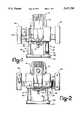
- FIG. 1is a front view of the plunge-type router
- FIG. 2is a rear view of the plunge-type router
- FIG. 3is a partial cross-sectional view of the motor housing 12
- FIG. 4is a partial cross-sectional view taken along lines 4--4 shown in FIG. 3;
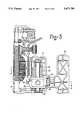
- FIG. 5is an exploded perspective view showing the individual elements of the locking mechanism internal to the motor housing
- FIG. 6is a partial cross-section view of an alternative embodiment of the invention.
- FIG. 7is an exploded perspective view showing the individual elements of the locking mechanism of the alternative embodiment of the invention shown in FIG. 6.
- a plunge-type router 10 incorporating an arrangement according to the inventionis shown in FIGS. 1 and 2.
- the router 10has a motor housing 12 which houses a drive motor 14 as shown in the cross-sectional view of FIG. 3.
- the drive motor 14has a shaft 16 which extends external to the motor housing 12 at a lower end thereof.
- a collet or chuck 18, adapted to hold a cutting tool,is attached to the distal end of the shaft 16 as shown.
- a base plate 20 having a work engaging surface 22is connected to the motor housing 12 by a pair of telescoping guides 24 and 26.
- Each of the telescoping guides 24 and 26consist of a guide sleeve 28 disposed inside the router housing 12 on opposite sides of the drive motor 14 and a guide tube 30 attached to said base plate 20.
- the guide tube 30is slidably received in the guide sleeve 28 as more clearly shown in FIG. 3.
- the guide tubes 30are disposed normal to the work engaging surface 22 of the base plate 20 and guide the displacement of the router 10 normal to the work engaging surface 22.
- the telescoping guides 24 and 26maintain the orientation of the router 10 relative to the base plate 20 and allow the router 10 to be displaced relative thereto.
- a coil spring 34is disposed within the telescoping guides 24 and 26 and resiliently biases the router 10 away from the base plate 20 with a force sufficient to counterbalance the gravitational forces acting on the router 10 when the telescoping guides 24 and 26 are vertically disposed.
- the operatorplaces the work engaging surface 22 of the base plate 20 on a surface of a workpiece.
- the operatorgrasps the handles 38 and 40, which are integral with the motor housing 12, and displaces the router 10 toward the workpiece against the force of the coil springs 34 until the cutting tool attached to collet 18 is at the desired location relative to the workpiece.
- a movable stop bar 42may be attached to the motor housing 12 to preset the location of the cutting tool relative to the workpiece.
- the stop bar 42may be locked in place by a clamp 44.
- a depth of cut locking mechanismfor locking the motor housing 12 to the telescoping guide 26 at the desired location, or any other location within the limits of the telescoping guides 24 and 26.
- the depth of cut locking mechanismconsists of a release lever 46 pivotably mounted to the motor housing 12.
- the release lever 46has an internal portion 48 which is pivotably connected to a pivot pin 50 and an external portion 52 extending through a slot provided in the motor housing 12 and is accessible to the operator when he grasps the handle 40.
- An actuator rod 54connects the internal portion 48 of the release lever 46 to a lock disc 56.
- One end of the actuator rod 54has a first tang received in an appropriate aperture 58 provided in the internal portion 48 of the release lever 46 and the other end of the actuator rod 54 has a second tang received in an appropriate aperture 60 provided through a disc portion 62 of the lock disc 56.
- the disc portion 62 of the lock disc 56has at least two (2) diametrically opposed apertures 60, as shown in FIG. 5.
- the lock disc 56has a left hand threaded boss 64, which is threadably received in a threaded aperture 66 provided in sleeve clamp 68.
- the sleeve clamp 68secures the guide sleeve 28 in the motor housing 12.
- the sleeve clamp 68is secured to an internal boss 70 provided in the motor housing 12 by threaded fasteners, such as bolts 74 and 76.
- the lock disc 56also has a spring guide boss 78 provided on the side of the disc portion 62 opposite the threaded boss 64 and a bore 80 provided therethrough concentric with the spring guide and threaded bosses 78 and 64, respectively.
- the bore 80is threaded at least part way therethrough as shown in FIG. 5.
- a brass plug 82is slidably received in the bore 80 and passes through a concentric clearance aperture 84 provided in the sleeve guide 28 to engage the guide tube 30.
- a set screw 86is threadably received in the threaded bore 80 to urge the brass plug 82 into locking engagement with the guide tube 30 when the release lever 46 is resiliently biased to the position shown in FIG. 4 as shall be explained hereinafter.
- the disc portion 62 of the lock disc 56also has at least one spring tang bore 88.
- the disc portion 62has two diametrically opposed spring tang bores 88, as shown in FIG. 5.
- a torsional spring 90is disposed in a well 92 provided in the motor housing 12.
- the torque spring 90has a first tang 94 provided at one end thereof which extends in an axial direction and is receivable in one of the spring tang bores 88 of the lock disc 56.
- a second tang 96is disposed in an inward radial direction and is received in a slot 98 in a ratchet member 100 disposed at the bottom of the well 92.
- the ratchet member 100has a cylindrical spring guide portion 102 in which is formed a slot 98 and a ratchet portion 104 having a series of radially extending unidirectional ratchet teeth 106 which engage a mating set of unidirectional ratchet teeth 108 provided at the bottom of well 92.
- the torsional spring 90also provides a resilient axial force urging the ratchet teeth 106 of the ratchet member 100 into locking engagement with the ratchet teeth 108 at the bottom of the well 92.
- the ratchet member 100has an axially disposed hexagonally-shaped through bore 110 sized to receive a standard size hexagonal wrench such as a standard size Allen wrench.
- the motor housing 12has a coaxially aligned aperture 112 which permits the Allen wrench to be inserted into the hexagonally-shaped through bore 110 from outside the motor housing 12.
- the set screw 86also has a hexagonally-shaped bore 114 adapted to receive a smaller Allen wrench.
- the hexagonally-shaped bore 114is smaller than hexagonally-shaped bore 110 and is axially aligned with and can rotate within the hexagonally-shaped bore 110 so that the smaller Allen wrench can be inserted into hexagonally-shaped bore 114 through the aperture 112 provided in the motor housing 12 and the hexagonally-shaped through bore 110.
- the location of the brass plug 82is adjusted by rotating set screw 86 so that when the lock disc 56 is rotated to its unlocked position by the displacement of the release lever 46 in a counter-clockwise direction indicated by arrow 32 as shown in FIG. 4 to an unlocked position adjacent to the end 116 of the slot provided in the motor housing 12, the brass plug 82 will be disengaged from the guide tube 30.
- the lock disc 56is rotated in a clockwise direction to its lock position by the torsional spring 90, the brass plug will forcibly engage the guide tube 30 frictionally locking the guide tube 30 within the guide sleeve 28 and the release lever 46 will be returned to the other end 118 of the slot.
- the ratchet member 100With the lock disc in its locked position, the ratchet member 100 is rotated in a counter-clockwise direction until the torque exerted by torsional spring 90 on the lock disc 56 is sufficient to produce an axial force on the brass plug 82 to frictionally lock the guide tube 30 to the guide sleeve 28.
- a release lever locking mechanism 120is also provided to lock the release lever 46 in the unlocked position.
- the release lever locking mechanism 120consists of a spring-loaded button 122 provided on the side of the motor housing 12 opposite the release lever 46.
- the spring-loaded button 122has a shaft 124 which extends into the motor housing 12 through an aperture 126 to a location adjacent to the end of the internal portion 48 of the release lever 46.
- a dog 128is provided on the end of the internal portion 48 of the release lever 46 which is engageable by a dog catch 130 provided on the end of the shaft 124 when the release handle 46 is displaced counter-clockwise to the released position and the button 122 is depressed.
- release lever 46Releasing the release lever 46 from the release position with the button 122 depressed will frictionally engage the dog catch 130 with the dog 128 holding the button in the depressed position. A subsequent displacement of the release lever 48 in a counter-clockwise direction will disengage the dog catch 130 from the dog 128 permitting the spring 132 to return the button 122 to its undepressed location. The release lever 46 then may be fully displaced clockwise to its lock position.
- FIGS. 6 and 7An alternative embodiment of the depth of cut locking mechanism 220 is illustrated in FIGS. 6 and 7.
- the front, rear and cross-sectional views of a plunge type router incorporating the alternative embodiment of the locking mechanismare substantially similar to FIGS. 1, 2 and 3 illustrating the first embodiment and are therefore now repeated. Since many of the components of alternative locking mechanism 220 are identical to first embodiment of locking mechanism 120 to the extent possible, numbers of components have been increased the value of 100 so that the description of the second embodiment can focus on the differences between the two mechanisms.
- Locking mechanism 220 of the second embodimentlooks very similar to locking mechanism 120, however, the locking mechanism maintains the housing in the normally released state so that it can move axially relative to the pair of router guide tubes 126 projecting upwardly from the router base plate.
- Lever 146is pivotably connected to housing 134 by pivot pin 150.
- Lever 146is free to rotatably pivot about pivot axis 210 which extends parallel to guide tube 136.
- Lever 146is provided with an internal portion 148 located within router housing 134 and an external portion 152 located external to the housing adjacent router handle 140.
- Lever external portion 152is located adjacent the handle so that a user grasping the router handle can reach the lever external portion 152 and rotate the lever toward the handle in the direction of arrow 32 thereby causing the locking mechanism 220 to lock the motor housing assembly relative to the base planing end shafts.
- lever 146is coupled to lock disc 156 via an actuator rod 154 which causes the lock disc 156 to rotate in response to the movement of lever 146.
- lock disc 156is simply a matter of design choice and is used main common parts with the prior embodiment. It should be appreciated that a non-circular lock member having an arm extending from a threaded boss would function quite satisfactorily.
- the lock disclocks guide sleeve to the guide tube when the disc was rotated counter-clockwise.
- the lock discwhen rotated clockwise locks the guide sleeve 138 to guide tube 136.
- Guide sleeve clamp 168is provided with a boss having a threaded aperture 166.
- the boss apertureis provided with right hand threads since it is desired to cause the lock disc to move inwardly toward guide tube 136 in response to lever 146 being pulled toward handle 140 by the user.
- Lock disc 156is provided with a threaded boss 164 which cooperates with the threaded aperture 166 in sleeve clamp 168. Like the previous embodiment, lock disc 156 is provided with an internal threaded bore 180 which receives hexagonal drive set screw 186. In the embodiment illustrated, set screw 186 directly engages guide tube 136 to serve as a friction member cooperating with the lock disc to engage the guide tube in response to the axial displacement of the lock disc when the disc is rotated to the locked position.
- a replaceable soft metal plugsuch as brass plug 82 shown in FIG. 5 can be interposed between set screw 186 and guide tube 136.
- the advantage of a soft metal plugis that the plug need not rotate and the surface engaging guide tube 136 can wear to form a semi-cylindrical surface having greater contact are than the line contact inherent with a set screw.
- guide sleeve 138is provided with an aperture generally aligned with threaded aperture 166 and bracket 168 enabling the set screw and/or soft metal plug to directly engage the guide tube 136.
- a return spring 234is provided which biases the lever 146 to an unlocked position, i.e. biased away from handle 140.
- the userwho would extend the finger tips of his or her left hand and pull the lever free end 152 toward handle 140.
- ball 228engages detent recess 230 in lever 146.
- Ball 228is biased by coil spring 232 which urges the ball into engagement with detent recess 230. This detent mechanism provides sufficient load to maintain the lever 146 in the locked position in spite of the load of return spring 234 which urges the lever back to the locked position.
- the detent mechanism of the alternative embodiment shown in FIGS. 6-7is used to retain the lock disc in the locked position, while the detent mechanism described with reference to the first embodiment and shown in FIG. 4, maintains the lock disc in the unlocked position.
- the systemshave much in common.
- Eachuses a lock or detent mechanism to retain the lock disc in one of a lock or release positions and a spring is provided for urging the lock disc to the other offset lock and unlocked positions.
- torsion spring 90acts directly upon lock disc 56
- the torsion spring 234acts upon lever 146. Since the lever and locking disc are interconnected by actuator rod 54 and 154 where the spring is located is simply a matter of design choice.
- Levers 46 and 146 in the first and second embodimentsare each pivotably connected to the router housing and rotatable about a pivot axis which extends parallel and spaced adjacent to guide tube. Pivoting levers 46 and 146 about the lever pivot axis causes lock discs 56 and 156 to rotate upon an axis normal to guide tube then respective guide tubes.
Landscapes
- Life Sciences & Earth Sciences (AREA)
- Engineering & Computer Science (AREA)
- Mechanical Engineering (AREA)
- Wood Science & Technology (AREA)
- Forests & Forestry (AREA)
- Milling, Drilling, And Turning Of Wood (AREA)
Abstract
Description
Claims (16)
Priority Applications (1)
| Application Number | Priority Date | Filing Date | Title |
|---|---|---|---|
| US08/321,149US5671789A (en) | 1993-09-16 | 1994-10-11 | Depth of cut locking mechanism for a plunge-type router |
Applications Claiming Priority (2)
| Application Number | Priority Date | Filing Date | Title |
|---|---|---|---|
| US08/122,390US5353852A (en) | 1993-09-16 | 1993-09-16 | Depth of cut locking mechanism for a plunge-type router |
| US08/321,149US5671789A (en) | 1993-09-16 | 1994-10-11 | Depth of cut locking mechanism for a plunge-type router |
Related Parent Applications (1)
| Application Number | Title | Priority Date | Filing Date |
|---|---|---|---|
| US08/122,390Continuation-In-PartUS5353852A (en) | 1993-09-16 | 1993-09-16 | Depth of cut locking mechanism for a plunge-type router |
Publications (1)
| Publication Number | Publication Date |
|---|---|
| US5671789Atrue US5671789A (en) | 1997-09-30 |
Family
ID=22402430
Family Applications (2)
| Application Number | Title | Priority Date | Filing Date |
|---|---|---|---|
| US08/122,390Expired - Fee RelatedUS5353852A (en) | 1993-09-16 | 1993-09-16 | Depth of cut locking mechanism for a plunge-type router |
| US08/321,149Expired - Fee RelatedUS5671789A (en) | 1993-09-16 | 1994-10-11 | Depth of cut locking mechanism for a plunge-type router |
Family Applications Before (1)
| Application Number | Title | Priority Date | Filing Date |
|---|---|---|---|
| US08/122,390Expired - Fee RelatedUS5353852A (en) | 1993-09-16 | 1993-09-16 | Depth of cut locking mechanism for a plunge-type router |
Country Status (3)
| Country | Link |
|---|---|
| US (2) | US5353852A (en) |
| JP (1) | JPH07100801A (en) |
| DE (1) | DE4432347A1 (en) |
Cited By (54)
| Publication number | Priority date | Publication date | Assignee | Title |
|---|---|---|---|---|
| US5829931A (en)* | 1996-08-09 | 1998-11-03 | S-B Power Tool Company | Removable depth guide for rotary cutting tool |
| USD416460S (en) | 1998-11-16 | 1999-11-16 | Porter-Cable Corporation | Plunge router |
| US5988241A (en)* | 1998-11-16 | 1999-11-23 | Porter-Cable Corporation | Ergonomic router handles |
| US5998897A (en)* | 1998-11-16 | 1999-12-07 | Porter-Cable Corporation | Router chuck mounting system |
| GB2341344A (en)* | 1998-09-12 | 2000-03-15 | Paul Firby | Plug trimmer. |
| US6065912A (en)* | 1998-11-16 | 2000-05-23 | Porter-Cable Corporation | Router switching system |
| US6079915A (en)* | 1998-11-16 | 2000-06-27 | Porter-Cable Corporation | Plunge router depth stop system |
| US6113323A (en)* | 1998-11-16 | 2000-09-05 | Porter-Cable Corporation | Plunge router sub-base alignment |
| US6139229A (en)* | 1998-11-16 | 2000-10-31 | Porter-Cable Corporation | Plunge router fine depth adjustment system |
| USD444364S1 (en) | 2000-06-09 | 2001-07-03 | Black & Decker Inc. | Router |
| US6261036B1 (en) | 1998-11-16 | 2001-07-17 | Porter-Cable Corporation | Plunge router locking system |
| USD450230S1 (en) | 2001-01-29 | 2001-11-13 | One World Technologies, Inc. | Pair of ergonomic router handles |
| US6443676B1 (en)* | 2000-07-11 | 2002-09-03 | Roto Zip Tool Corporation | Automatic locking depth guide for cutting tools and the like |
| US6474378B1 (en)* | 2001-05-07 | 2002-11-05 | S-B Power Tool Company | Plunge router having electronic depth adjustment |
| USD465393S1 (en) | 2001-08-10 | 2002-11-12 | Roto Zip Tool Corporation | Automatic locking depth guide |
| USD465712S1 (en) | 2001-08-10 | 2002-11-19 | Roto Zip Tool Corporation | Power tool with automatic locking depth guide |
| US6488455B1 (en)* | 2000-07-28 | 2002-12-03 | S-B Power Tool Company | Plunge base router |
| USD473770S1 (en) | 2001-08-10 | 2003-04-29 | Roto Zip Tool Corporation | Power tool with automatic locking depth guide |
| USD487009S1 (en) | 2002-08-21 | 2004-02-24 | Milwaukee Electric Tool Corporation | Router base |
| USD489592S1 (en) | 2002-08-21 | 2004-05-11 | Milwaukee Electric Tool Corporation | Handle |
| US20040194854A1 (en)* | 2000-08-11 | 2004-10-07 | Milwaukee Electric Tool Corporation | Router |
| US20040253068A1 (en)* | 2000-08-14 | 2004-12-16 | Graham Gerhardt | Electric power tool |
| US6863480B1 (en) | 2002-08-06 | 2005-03-08 | Porter-Cable Corporation | Router plunge depth adjustment mechanism |
| US20050072490A1 (en)* | 2003-10-07 | 2005-04-07 | Baber Brad M. | Power tool support fixture |
| US20050201839A1 (en)* | 2004-03-11 | 2005-09-15 | Credo Technology Corporation | Plunge-type router having improved plunge return capability |
| US20050211335A1 (en)* | 2001-07-30 | 2005-09-29 | Garcia Jaime E | Planer apparatus |
| USD510246S1 (en)* | 2003-10-27 | 2005-10-04 | Gmca Pty Ltd. | Router |
| US6986369B1 (en) | 2002-11-12 | 2006-01-17 | Porter-Cable Corporation | Router height adjustment apparatus |
| US20060086417A1 (en)* | 2002-10-15 | 2006-04-27 | Griffin Greg K | Router base securing mechanism |
| US20060102248A1 (en)* | 2002-10-15 | 2006-05-18 | Cooper Randy G | Depth adjustment mechanism |
| US20060108024A1 (en)* | 2003-05-01 | 2006-05-25 | Cooper Randy G | Ergonomic router |
| US7108464B2 (en) | 2002-10-15 | 2006-09-19 | Black & Decker Inc. | Switch assembly |
| USD531871S1 (en) | 2005-06-16 | 2006-11-14 | Black & Decker Inc. | Router |
| US20060269377A1 (en)* | 2005-05-24 | 2006-11-30 | Akira Onose | Power tool |
| USD536232S1 (en) | 2003-08-15 | 2007-02-06 | Credo Technology Corporation | Router handles |
| US20070095429A1 (en)* | 2002-08-21 | 2007-05-03 | Hessenberger Jeffrey C | Router |
| USD546654S1 (en) | 2004-01-29 | 2007-07-17 | Black & Decker Inc. | Router with plunge base |
| US7275900B1 (en) | 2003-07-25 | 2007-10-02 | Black & Decker Inc. | Router elevating mechanism |
| US7290575B2 (en) | 2003-07-09 | 2007-11-06 | Credo Technology Corporation | Hybrid router |
| US7316528B2 (en) | 2002-10-15 | 2008-01-08 | Black & Decker Inc. | Ergonomic router assembly |
| US20080008551A1 (en)* | 2005-07-07 | 2008-01-10 | Black & Decker Inc. | Router |
| USD564850S1 (en) | 2006-09-26 | 2008-03-25 | Jinding Group Co., Ltd. | Portion of a tool housing |
| WO2008025350A3 (en)* | 2006-08-28 | 2008-04-17 | Stephan Rieth | Milling tool, in particular hand milling machine for milling bevels |
| US20080237417A1 (en)* | 2007-03-30 | 2008-10-02 | Hsu Hsiu-Kwei Liu | Elevating mechanism for woodworking |
| US7451791B2 (en) | 2002-10-15 | 2008-11-18 | Black & Decker Inc. | Handle assembly |
| USD584590S1 (en)* | 2004-10-29 | 2009-01-13 | Balck & Decker Inc. | Router |
| USD588428S1 (en)* | 2004-10-14 | 2009-03-17 | Black & Decker Inc. | Router |
| USD611509S1 (en)* | 2007-08-20 | 2010-03-09 | Milwaukee Electric Tool Corporation | Portion of a router |
| US20100126627A1 (en)* | 2000-08-11 | 2010-05-27 | Goddard Jay A | Router |
| US7900661B2 (en) | 2007-08-20 | 2011-03-08 | Milwaukee Electric Tool Corporation | Plunge router and kit |
| CN103836068A (en)* | 2014-01-21 | 2014-06-04 | 燕山大学 | Stepless accurate positioning and locking device for large-scale heavy-load guide-rail type mobile platform |
| US20140271015A1 (en)* | 2013-03-14 | 2014-09-18 | Robert Bosch Gmbh | One handed plunge base for a router |
| WO2018184854A1 (en)* | 2017-04-04 | 2018-10-11 | Robert Bosch Gmbh | Lock device for power tool adjustment |
| US12285881B2 (en) | 2019-05-15 | 2025-04-29 | Milwaukee Electric Tool Corporation | Offset base for router |
Families Citing this family (5)
| Publication number | Priority date | Publication date | Assignee | Title |
|---|---|---|---|---|
| GB9404002D0 (en)* | 1994-03-02 | 1994-04-20 | Black & Decker Inc | Improvements relating to power tools |
| US6745449B2 (en)* | 2001-11-06 | 2004-06-08 | Raytheon Company | Method and apparatus for making a lid with an optically transmissive window |
| AU306747S (en)* | 2005-06-22 | 2006-05-12 | Black & Decker Inc | A router |
| USD601396S1 (en)* | 2008-08-20 | 2009-10-06 | Makita Corporation | Portable electric router |
| JP2014148017A (en)* | 2013-02-01 | 2014-08-21 | Makita Corp | Hand-held electric cutter |
Citations (8)
| Publication number | Priority date | Publication date | Assignee | Title |
|---|---|---|---|---|
| US3908510A (en)* | 1974-07-01 | 1975-09-30 | Intertherm | Adjustable depth router |
| US4239428A (en)* | 1979-05-24 | 1980-12-16 | Berzina James A | Router adjustment attachment |
| US4319860A (en)* | 1980-02-29 | 1982-03-16 | Black & Decker Inc. | Plunge type router |
| US4566830A (en)* | 1983-04-21 | 1986-01-28 | Peter Maier | Router with quick depth of cut adjustment |
| US4652191A (en)* | 1986-02-04 | 1987-03-24 | Lucien Bernier | Press router |
| US4770573A (en)* | 1986-10-15 | 1988-09-13 | Ryobi Ltd. | Cutting depth adjusting mechanism of a router |
| US5191921A (en)* | 1991-10-18 | 1993-03-09 | Ryobi Motor Products Corp. | Adjustable depth of cut stop mechanism for a plunge type router |
| US5273089A (en)* | 1991-12-03 | 1993-12-28 | Robert Bosch Gmbh | Routing machine |
Family Cites Families (3)
| Publication number | Priority date | Publication date | Assignee | Title |
|---|---|---|---|---|
| US2867251A (en)* | 1957-05-21 | 1959-01-06 | Millers Falls Co | Router depth adjustment means |
| US4051880A (en)* | 1976-10-29 | 1977-10-04 | The Singer Company | Dustless routers |
| US5143494A (en)* | 1991-10-18 | 1992-09-01 | Ryobi Motor Products Corp. | Depth of cut lock mechanism for a plunge type router |
- 1993
- 1993-09-16USUS08/122,390patent/US5353852A/ennot_activeExpired - Fee Related
- 1994
- 1994-06-23JPJP6164544Apatent/JPH07100801A/enactivePending
- 1994-09-12DEDE4432347Apatent/DE4432347A1/ennot_activeWithdrawn
- 1994-10-11USUS08/321,149patent/US5671789A/ennot_activeExpired - Fee Related
Patent Citations (8)
| Publication number | Priority date | Publication date | Assignee | Title |
|---|---|---|---|---|
| US3908510A (en)* | 1974-07-01 | 1975-09-30 | Intertherm | Adjustable depth router |
| US4239428A (en)* | 1979-05-24 | 1980-12-16 | Berzina James A | Router adjustment attachment |
| US4319860A (en)* | 1980-02-29 | 1982-03-16 | Black & Decker Inc. | Plunge type router |
| US4566830A (en)* | 1983-04-21 | 1986-01-28 | Peter Maier | Router with quick depth of cut adjustment |
| US4652191A (en)* | 1986-02-04 | 1987-03-24 | Lucien Bernier | Press router |
| US4770573A (en)* | 1986-10-15 | 1988-09-13 | Ryobi Ltd. | Cutting depth adjusting mechanism of a router |
| US5191921A (en)* | 1991-10-18 | 1993-03-09 | Ryobi Motor Products Corp. | Adjustable depth of cut stop mechanism for a plunge type router |
| US5273089A (en)* | 1991-12-03 | 1993-12-28 | Robert Bosch Gmbh | Routing machine |
Cited By (102)
| Publication number | Priority date | Publication date | Assignee | Title |
|---|---|---|---|---|
| US5829931A (en)* | 1996-08-09 | 1998-11-03 | S-B Power Tool Company | Removable depth guide for rotary cutting tool |
| GB2341344A (en)* | 1998-09-12 | 2000-03-15 | Paul Firby | Plug trimmer. |
| US6079915A (en)* | 1998-11-16 | 2000-06-27 | Porter-Cable Corporation | Plunge router depth stop system |
| US5998897A (en)* | 1998-11-16 | 1999-12-07 | Porter-Cable Corporation | Router chuck mounting system |
| US5988241A (en)* | 1998-11-16 | 1999-11-23 | Porter-Cable Corporation | Ergonomic router handles |
| US6065912A (en)* | 1998-11-16 | 2000-05-23 | Porter-Cable Corporation | Router switching system |
| US6113323A (en)* | 1998-11-16 | 2000-09-05 | Porter-Cable Corporation | Plunge router sub-base alignment |
| US6139229A (en)* | 1998-11-16 | 2000-10-31 | Porter-Cable Corporation | Plunge router fine depth adjustment system |
| US6261036B1 (en) | 1998-11-16 | 2001-07-17 | Porter-Cable Corporation | Plunge router locking system |
| USD416460S (en) | 1998-11-16 | 1999-11-16 | Porter-Cable Corporation | Plunge router |
| USD444364S1 (en) | 2000-06-09 | 2001-07-03 | Black & Decker Inc. | Router |
| US6443676B1 (en)* | 2000-07-11 | 2002-09-03 | Roto Zip Tool Corporation | Automatic locking depth guide for cutting tools and the like |
| US6854938B2 (en) | 2000-07-11 | 2005-02-15 | Credo Technology Corporation | Automatic locking depth guide for cutting tools and the like |
| US6488455B1 (en)* | 2000-07-28 | 2002-12-03 | S-B Power Tool Company | Plunge base router |
| US6619894B2 (en) | 2000-07-28 | 2003-09-16 | S-B Power Tool Company | Plunge base router |
| US20100126627A1 (en)* | 2000-08-11 | 2010-05-27 | Goddard Jay A | Router |
| US7556070B2 (en) | 2000-08-11 | 2009-07-07 | Milwaukee Electric Tool Corporation | Router |
| US7207362B2 (en) | 2000-08-11 | 2007-04-24 | Milwaukee Electric Tool Corporation | Router |
| US6991008B2 (en) | 2000-08-11 | 2006-01-31 | Milwaukee Electric Tool Corporation | Router |
| US8087437B2 (en) | 2000-08-11 | 2012-01-03 | Techtronic Power Tools Technology Limited | Router |
| US7370679B2 (en) | 2000-08-11 | 2008-05-13 | Milwaukee Electric Tool Corporation | Router |
| US20040194854A1 (en)* | 2000-08-11 | 2004-10-07 | Milwaukee Electric Tool Corporation | Router |
| US20040200543A1 (en)* | 2000-08-11 | 2004-10-14 | Milwaukee Tool Corporation | Router |
| US7523772B2 (en) | 2000-08-11 | 2009-04-28 | Milwaukee Electric Tool Corporation | Router |
| US6951232B2 (en) | 2000-08-11 | 2005-10-04 | Milwaukee Electric Tool Corporation | Router |
| US7677280B2 (en) | 2000-08-11 | 2010-03-16 | Milwaukee Electric Tool Corporation | Router |
| US7669620B2 (en) | 2000-08-11 | 2010-03-02 | Milwaukee Electric Tool Corporation | Router |
| US20050189039A1 (en)* | 2000-08-11 | 2005-09-01 | Milwaukee Electric Tool Corporation | Router |
| US6896454B2 (en)* | 2000-08-14 | 2005-05-24 | Hills Industries Limited | Electric power tool |
| US20040253068A1 (en)* | 2000-08-14 | 2004-12-16 | Graham Gerhardt | Electric power tool |
| USD450230S1 (en) | 2001-01-29 | 2001-11-13 | One World Technologies, Inc. | Pair of ergonomic router handles |
| US6474378B1 (en)* | 2001-05-07 | 2002-11-05 | S-B Power Tool Company | Plunge router having electronic depth adjustment |
| US20050211335A1 (en)* | 2001-07-30 | 2005-09-29 | Garcia Jaime E | Planer apparatus |
| US6951231B2 (en)* | 2001-07-30 | 2005-10-04 | Black And Decker, Inc. | Planer apparatus |
| US20050224140A1 (en)* | 2001-07-30 | 2005-10-13 | Garcia Jaime E | Planer apparatus |
| US20050224141A1 (en)* | 2001-07-30 | 2005-10-13 | Garcia Jaime E | Planer apparatus |
| US7055561B2 (en) | 2001-07-30 | 2006-06-06 | Delta International Machinery Corp. | Planer apparatus |
| US7546859B2 (en) | 2001-07-30 | 2009-06-16 | Black & Decker Inc. | Planer apparatus |
| USD465712S1 (en) | 2001-08-10 | 2002-11-19 | Roto Zip Tool Corporation | Power tool with automatic locking depth guide |
| USD465393S1 (en) | 2001-08-10 | 2002-11-12 | Roto Zip Tool Corporation | Automatic locking depth guide |
| USD473770S1 (en) | 2001-08-10 | 2003-04-29 | Roto Zip Tool Corporation | Power tool with automatic locking depth guide |
| US20060280570A1 (en)* | 2002-08-06 | 2006-12-14 | Black & Decker Inc. | Router plunge depth adjustment mechanism |
| US6863480B1 (en) | 2002-08-06 | 2005-03-08 | Porter-Cable Corporation | Router plunge depth adjustment mechanism |
| US20080069655A1 (en)* | 2002-08-06 | 2008-03-20 | Black & Decker Inc. | Router plunge depth adjustment mechanism |
| US20060140735A1 (en)* | 2002-08-06 | 2006-06-29 | Mike Taylor | Router plunge depth adjustment mechanism |
| US6926479B1 (en) | 2002-08-06 | 2005-08-09 | Porter-Cable Corporation | Router plunge depth adjustment mechanism |
| US7588400B2 (en) | 2002-08-06 | 2009-09-15 | Black & Decker Inc. | Router plunge depth adjustment mechanism |
| US7281887B2 (en)* | 2002-08-06 | 2007-10-16 | Black & Decker Inc. | Router plunge depth adjustment mechanism |
| US7255520B2 (en) | 2002-08-06 | 2007-08-14 | Black & Decker Inc. | Router plunge depth adjustment mechanism |
| USD489592S1 (en) | 2002-08-21 | 2004-05-11 | Milwaukee Electric Tool Corporation | Handle |
| US7637294B2 (en) | 2002-08-21 | 2009-12-29 | Milwaukee Electric Tool Corporation | Router |
| US7438095B2 (en) | 2002-08-21 | 2008-10-21 | Milwaukee Electric Tool Corporation | Router |
| US20070095429A1 (en)* | 2002-08-21 | 2007-05-03 | Hessenberger Jeffrey C | Router |
| US20090010730A1 (en)* | 2002-08-21 | 2009-01-08 | Hessenberger Jeffrey C | Router |
| USD487009S1 (en) | 2002-08-21 | 2004-02-24 | Milwaukee Electric Tool Corporation | Router base |
| US7334614B2 (en) | 2002-10-15 | 2008-02-26 | Black & Decker Inc. | Depth adjustment mechanism |
| US7108464B2 (en) | 2002-10-15 | 2006-09-19 | Black & Decker Inc. | Switch assembly |
| US7316528B2 (en) | 2002-10-15 | 2008-01-08 | Black & Decker Inc. | Ergonomic router assembly |
| US7686046B2 (en) | 2002-10-15 | 2010-03-30 | Black & Decker Inc. | Router base securing mechanism |
| US7334613B2 (en) | 2002-10-15 | 2008-02-26 | Black & Decker Inc. | Router base securing mechanism |
| US20060102248A1 (en)* | 2002-10-15 | 2006-05-18 | Cooper Randy G | Depth adjustment mechanism |
| US7654294B2 (en) | 2002-10-15 | 2010-02-02 | Black & Decker Inc. | Handle assembly |
| US7451791B2 (en) | 2002-10-15 | 2008-11-18 | Black & Decker Inc. | Handle assembly |
| US20060086417A1 (en)* | 2002-10-15 | 2006-04-27 | Griffin Greg K | Router base securing mechanism |
| US6986369B1 (en) | 2002-11-12 | 2006-01-17 | Porter-Cable Corporation | Router height adjustment apparatus |
| US7490642B1 (en) | 2002-11-12 | 2009-02-17 | Black & Decker Inc. | Router height adjustment apparatus |
| US20060108024A1 (en)* | 2003-05-01 | 2006-05-25 | Cooper Randy G | Ergonomic router |
| US7089979B2 (en) | 2003-05-01 | 2006-08-15 | Black & Decker Inc. | Ergonomic router |
| US7290575B2 (en) | 2003-07-09 | 2007-11-06 | Credo Technology Corporation | Hybrid router |
| US7578325B2 (en) | 2003-07-09 | 2009-08-25 | Credo Technology Corporation | Hybrid router |
| US20080000546A1 (en)* | 2003-07-09 | 2008-01-03 | Freese John B | Hybrid router |
| US7275900B1 (en) | 2003-07-25 | 2007-10-02 | Black & Decker Inc. | Router elevating mechanism |
| US7402008B2 (en) | 2003-07-25 | 2008-07-22 | Black & Decker Inc. | Router elevating mechanism |
| USD536232S1 (en) | 2003-08-15 | 2007-02-06 | Credo Technology Corporation | Router handles |
| US20050072490A1 (en)* | 2003-10-07 | 2005-04-07 | Baber Brad M. | Power tool support fixture |
| US7290574B2 (en)* | 2003-10-07 | 2007-11-06 | Credo Technology Corporation | Power tool support fixture |
| USD510246S1 (en)* | 2003-10-27 | 2005-10-04 | Gmca Pty Ltd. | Router |
| USD546654S1 (en) | 2004-01-29 | 2007-07-17 | Black & Decker Inc. | Router with plunge base |
| US20050201839A1 (en)* | 2004-03-11 | 2005-09-15 | Credo Technology Corporation | Plunge-type router having improved plunge return capability |
| US7018149B2 (en)* | 2004-03-11 | 2006-03-28 | Credo Technology Corporation | Plunge-type router having improved plunge return capability |
| USD588428S1 (en)* | 2004-10-14 | 2009-03-17 | Black & Decker Inc. | Router |
| USD584590S1 (en)* | 2004-10-29 | 2009-01-13 | Balck & Decker Inc. | Router |
| US20060269377A1 (en)* | 2005-05-24 | 2006-11-30 | Akira Onose | Power tool |
| US7367760B2 (en)* | 2005-05-24 | 2008-05-06 | Hitachi Koki Co., Ltd. | Power tool |
| US7726918B2 (en) | 2005-05-24 | 2010-06-01 | Hitachi Koki Co., Ltd. | Power tool |
| USD531871S1 (en) | 2005-06-16 | 2006-11-14 | Black & Decker Inc. | Router |
| US20080008551A1 (en)* | 2005-07-07 | 2008-01-10 | Black & Decker Inc. | Router |
| US7484915B2 (en) | 2005-07-07 | 2009-02-03 | Black & Decker Inc. | Router |
| US8146629B2 (en) | 2005-07-07 | 2012-04-03 | Black & Decker, Inc. | Router |
| US20090114314A1 (en)* | 2005-07-07 | 2009-05-07 | Black & Decker Inc. | Router |
| WO2008025350A3 (en)* | 2006-08-28 | 2008-04-17 | Stephan Rieth | Milling tool, in particular hand milling machine for milling bevels |
| USD564850S1 (en) | 2006-09-26 | 2008-03-25 | Jinding Group Co., Ltd. | Portion of a tool housing |
| US20080237417A1 (en)* | 2007-03-30 | 2008-10-02 | Hsu Hsiu-Kwei Liu | Elevating mechanism for woodworking |
| US7900661B2 (en) | 2007-08-20 | 2011-03-08 | Milwaukee Electric Tool Corporation | Plunge router and kit |
| USD611509S1 (en)* | 2007-08-20 | 2010-03-09 | Milwaukee Electric Tool Corporation | Portion of a router |
| US20140271015A1 (en)* | 2013-03-14 | 2014-09-18 | Robert Bosch Gmbh | One handed plunge base for a router |
| US9403221B2 (en)* | 2013-03-14 | 2016-08-02 | Robert Bosch Gmbh | One handed plunge base for a router |
| CN103836068A (en)* | 2014-01-21 | 2014-06-04 | 燕山大学 | Stepless accurate positioning and locking device for large-scale heavy-load guide-rail type mobile platform |
| CN103836068B (en)* | 2014-01-21 | 2016-03-02 | 燕山大学 | The stepless accurate positioning locking device of large-scale heavy duty mobile platform guide rail class |
| WO2018184854A1 (en)* | 2017-04-04 | 2018-10-11 | Robert Bosch Gmbh | Lock device for power tool adjustment |
| US10556311B2 (en)* | 2017-04-04 | 2020-02-11 | Robert Bosch Gmbh | Lock device for power tool adjustment |
| US12285881B2 (en) | 2019-05-15 | 2025-04-29 | Milwaukee Electric Tool Corporation | Offset base for router |
Also Published As
| Publication number | Publication date |
|---|---|
| DE4432347A1 (en) | 1995-03-23 |
| JPH07100801A (en) | 1995-04-18 |
| US5353852A (en) | 1994-10-11 |
Similar Documents
| Publication | Publication Date | Title |
|---|---|---|
| US5671789A (en) | Depth of cut locking mechanism for a plunge-type router | |
| US5143494A (en) | Depth of cut lock mechanism for a plunge type router | |
| EP0554929B1 (en) | Blade collet | |
| US5191921A (en) | Adjustable depth of cut stop mechanism for a plunge type router | |
| US6196554B1 (en) | Locking chuck | |
| US6550786B2 (en) | Removable chuck | |
| US6053076A (en) | Offset head ratchet wrench | |
| US6334743B1 (en) | High-speed rotary machine | |
| USRE41857E1 (en) | Locking mechanism for inclination adjustment of a blade of a cutting device | |
| US7976253B2 (en) | Locking chuck | |
| EP3192620B1 (en) | Miter saw | |
| US5921730A (en) | Rotary power tool with remotely actuated chuck | |
| US8087437B2 (en) | Router | |
| WO2002026453A2 (en) | A hand-held turret drill | |
| CA2627947C (en) | Robust slide adjustable wrench | |
| US4326436A (en) | Combination adjustable/lockable/measuring wrench, and methods of constructing and utilizing same | |
| JPS63290537A (en) | Cleaning apparatus for polishing especially window glass | |
| US6164170A (en) | Semi-automatic screwdriver for collated screws | |
| GB2304067A (en) | Electric hammer drill | |
| WO2021219349A1 (en) | Power tool, locking system and plunge base | |
| US4492370A (en) | Quick release clamping device | |
| US2750829A (en) | Power drive and locking mechanism for | |
| US4234177A (en) | Differential screw device for workholders and the like | |
| JP7755957B2 (en) | Side handle for power tool and power tool | |
| US5893305A (en) | Semi-automatic pistolled screwdriver with thorny rings |
Legal Events
| Date | Code | Title | Description |
|---|---|---|---|
| AS | Assignment | Owner name:RYOBI NORTH AMERICA, INC., SOUTH CAROLINA Free format text:ASSIGNMENT OF ASSIGNORS INTEREST;ASSIGNORS:STOLZER, J. TIMOTHY;MCCURRY, RONALD C.;WINCHESTER, CHARLES D.;REEL/FRAME:007339/0913 Effective date:19941213 | |
| AS | Assignment | Owner name:RYOBI NORTH AMERICA, INC., SOUTH CAROLINA Free format text:ASSIGNMENT OF ASSIGNORS INTEREST;ASSIGNOR:KIKUCHI, NAOKI;REEL/FRAME:007602/0468 Effective date:19950706 | |
| AS | Assignment | Owner name:HSBC BANK USA, NEW YORK Free format text:SECURITY INTEREST;ASSIGNORS:ONE WORLD TECHNOLOGIES INC.;RYOBI TECHNOLOGIES, INC.;OWT INDUSTRIES, INC.;REEL/FRAME:011103/0770 Effective date:20000801 | |
| AS | Assignment | Owner name:ONE WORLD TECHNOLOGIES, INC., SOUTH CAROLINA Free format text:ASSIGNMENT OF ASSIGNORS INTEREST;ASSIGNOR:RYOBI NORTH AMERICA, INC.;REEL/FRAME:011149/0407 Effective date:20000731 | |
| REMI | Maintenance fee reminder mailed | ||
| LAPS | Lapse for failure to pay maintenance fees | ||
| FP | Lapsed due to failure to pay maintenance fee | Effective date:20010930 | |
| AS | Assignment | Owner name:ONE WORLD TECHNOLOGIES LIMITED, BERMUDA Free format text:ASSIGNMENT OF ASSIGNORS INTEREST;ASSIGNOR:ONE WORLD TECHNOLOGIES, INC.;REEL/FRAME:014066/0731 Effective date:20030512 | |
| STCH | Information on status: patent discontinuation | Free format text:PATENT EXPIRED DUE TO NONPAYMENT OF MAINTENANCE FEES UNDER 37 CFR 1.362 |