US5671436A - Versatile RF data capture system - Google Patents
Versatile RF data capture systemDownload PDFInfo
- Publication number
- US5671436A US5671436AUS08/520,136US52013695AUS5671436AUS 5671436 AUS5671436 AUS 5671436AUS 52013695 AUS52013695 AUS 52013695AUS 5671436 AUS5671436 AUS 5671436A
- Authority
- US
- United States
- Prior art keywords
- information
- server
- memory
- data
- radio
- Prior art date
- Legal status (The legal status is an assumption and is not a legal conclusion. Google has not performed a legal analysis and makes no representation as to the accuracy of the status listed.)
- Expired - Lifetime
Links
Images


Classifications
- G—PHYSICS
- G06—COMPUTING OR CALCULATING; COUNTING
- G06F—ELECTRIC DIGITAL DATA PROCESSING
- G06F8/00—Arrangements for software engineering
- G06F8/60—Software deployment
- H—ELECTRICITY
- H04—ELECTRIC COMMUNICATION TECHNIQUE
- H04L—TRANSMISSION OF DIGITAL INFORMATION, e.g. TELEGRAPHIC COMMUNICATION
- H04L1/00—Arrangements for detecting or preventing errors in the information received
- H04L1/0001—Systems modifying transmission characteristics according to link quality, e.g. power backoff
- H04L1/0002—Systems modifying transmission characteristics according to link quality, e.g. power backoff by adapting the transmission rate
- H04L1/0003—Systems modifying transmission characteristics according to link quality, e.g. power backoff by adapting the transmission rate by switching between different modulation schemes
- H—ELECTRICITY
- H04—ELECTRIC COMMUNICATION TECHNIQUE
- H04L—TRANSMISSION OF DIGITAL INFORMATION, e.g. TELEGRAPHIC COMMUNICATION
- H04L1/00—Arrangements for detecting or preventing errors in the information received
- H04L1/0001—Systems modifying transmission characteristics according to link quality, e.g. power backoff
- H04L1/0023—Systems modifying transmission characteristics according to link quality, e.g. power backoff characterised by the signalling
- H04L1/0025—Transmission of mode-switching indication
- H—ELECTRICITY
- H04—ELECTRIC COMMUNICATION TECHNIQUE
- H04L—TRANSMISSION OF DIGITAL INFORMATION, e.g. TELEGRAPHIC COMMUNICATION
- H04L1/00—Arrangements for detecting or preventing errors in the information received
- H04L1/0001—Systems modifying transmission characteristics according to link quality, e.g. power backoff
- H04L1/0023—Systems modifying transmission characteristics according to link quality, e.g. power backoff characterised by the signalling
- H04L1/0032—Without explicit signalling
- H—ELECTRICITY
- H04—ELECTRIC COMMUNICATION TECHNIQUE
- H04L—TRANSMISSION OF DIGITAL INFORMATION, e.g. TELEGRAPHIC COMMUNICATION
- H04L1/00—Arrangements for detecting or preventing errors in the information received
- H04L1/12—Arrangements for detecting or preventing errors in the information received by using return channel
- H04L1/16—Arrangements for detecting or preventing errors in the information received by using return channel in which the return channel carries supervisory signals, e.g. repetition request signals
- H04L1/1607—Details of the supervisory signal
- H04L1/1671—Details of the supervisory signal the supervisory signal being transmitted together with control information
- H—ELECTRICITY
- H04—ELECTRIC COMMUNICATION TECHNIQUE
- H04L—TRANSMISSION OF DIGITAL INFORMATION, e.g. TELEGRAPHIC COMMUNICATION
- H04L1/00—Arrangements for detecting or preventing errors in the information received
- H04L1/12—Arrangements for detecting or preventing errors in the information received by using return channel
- H04L1/16—Arrangements for detecting or preventing errors in the information received by using return channel in which the return channel carries supervisory signals, e.g. repetition request signals
- H04L1/1607—Details of the supervisory signal
- H04L1/1685—Details of the supervisory signal the supervisory signal being transmitted in response to a specific request, e.g. to a polling signal
- H—ELECTRICITY
- H04—ELECTRIC COMMUNICATION TECHNIQUE
- H04W—WIRELESS COMMUNICATION NETWORKS
- H04W4/00—Services specially adapted for wireless communication networks; Facilities therefor
- H—ELECTRICITY
- H04—ELECTRIC COMMUNICATION TECHNIQUE
- H04M—TELEPHONIC COMMUNICATION
- H04M7/00—Arrangements for interconnection between switching centres
- H04M7/006—Networks other than PSTN/ISDN providing telephone service, e.g. Voice over Internet Protocol (VoIP), including next generation networks with a packet-switched transport layer
- H—ELECTRICITY
- H04—ELECTRIC COMMUNICATION TECHNIQUE
- H04W—WIRELESS COMMUNICATION NETWORKS
- H04W88/00—Devices specially adapted for wireless communication networks, e.g. terminals, base stations or access point devices
- H04W88/02—Terminal devices
- H—ELECTRICITY
- H04—ELECTRIC COMMUNICATION TECHNIQUE
- H04W—WIRELESS COMMUNICATION NETWORKS
- H04W88/00—Devices specially adapted for wireless communication networks, e.g. terminals, base stations or access point devices
- H04W88/14—Backbone network devices
Definitions
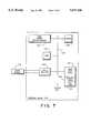
- the present inventionrelates to a data capture system 10 illustrated in FIG. 1 for entering data at a plurality of remote locations using means such as a plurality of portable data collection terminals 12a, b - - - n.
- the data capture system 10is applicable to receive and collect a wide variety of data and has found particular application in warehouses or retail store where a data capture system 10 would be used to keep an up-to-date record of the products to be marketed.
- the system 10would be capable of updating on a real time basis the inventory count of products, and to use stock locator data to identify where each product of the remaining inventory is stored, when a product is moved from one place to another, and which employee has current charge of that product.
- the price and sales person who sold the productare recorded.
- Such datamay be inputted into a terminal 12 by means of its keyboard 13.
- a terminal usercould count the number of one type of product and enter that number via the terminal's keyboard 13.
- datacould be entered to the terminal 10 via a CCD bar code scanner 22, which is electrically coupled by a cable 20 to its terminal 12.
- the scanner as illustratively identified in FIG. 1 by the numeral 22a and its terminal 12acould take the form of that modular scanner/terminal described in PCT international application W090/16033 published Dec. 27, 1990. Differing types of scanners 22b and 22n could also be used with the terminals 12 and may illustratively take the form of those scanners described in U.S. Pat. Nos.
- the data capture system 10utilizes illustratively RF transmission to bilaterally transmit data between each of the plurality of terminals 12a, b - - - n and a base radio transceiver 14.
- the base radio transceivermay illustratively take the form of that model RB3000 base radio transceiver manufactured by Norand Corporation, Cedar Rapids of Iowa.
- the base radio transceiver 14is connected via a communications multiplexer 16a or a communications controller 16b to a host computer 18.
- the multiplexer 16acould take the form of that model RM3200 as manufactured by Norand Corporation and the controller 16b could take the form of that controller identified as model RC2250 of Norand Corporation.
- the host computer 18may illustratively be an International Business Machines Corporation PC of AT class or higher. As illustrated in FIG. 1, the host computer 18 includes a keyboard 28, a display 24 and a system unit 26.
- Each of the portable data collection terminals 12a, b - - - nincludes a transceiver (not shown in FIG. 1) for transmitting RF messages to and from the base radio transceiver 14.
- a transmitted messagecomprises an initialization sequence, an address indicative of the particular terminal 12a, b- or n from or to which the message is directed, a message identifier and system information, the message data and/or control commands, error control, and an end of message indication.
- U.S. Pat. Nos. 4,910,794; 4,924,462; and 4,940,974each assigned to the assignee of this invention and incorporated herein by reference, provide further information on RF data collection terminals and systems.
- a RF data capture systemsimilar to that shown in FIG. 1 known as the RT1200 system of Norand Corporation
- controlled RF transmission between a plurality of terminals and a radio baseis established using a communications multiplexer similar to that of the multiplexer 16a shown in FIG. 1 to provide access to a particular one of the terminals 12a, b - - - n.
- the RT1200 systemutilizes time division multiplexing on a single frequency channel.
- the RT1200 communications protocolis based on a sequential polling method that transmits a query addressed to each portable terminal in succession, and allows a specified amount of time for the addressed terminal to respond when the addressed terminal has a data message ready for transmission.
- 4,940,974describes an improved, adaptive data communications system wherein the base radio transceiver 14 transmits a multi-terminal polling signal to each of its terminals 12a, b - - - n. That multi-terminal polling signal defines a series of successive response time slots in which the terminals 12 may randomly select to respond.
- a terminal 12 having a message to be transmitted to the host computer 18 via the base radio transceiver 14transmits a brief response burst in the selected time slot giving its own unique identification address.
- the base radio transceiver 14polls each of the responding terminals 12, ignoring those terminals without messages to be transmitted.
- This systemis adaptive in that the number of time slots may be changed depending upon the number of active terminals ready to transmit data messages.
- the present inventionis particularly related to adapting such data capture system 10 as shown in FIG. 1 to employ distributed processing concepts.
- Each of the portable data collection terminals 12has a computer processing capability in the illustrative form of a microprocessor, whereby the entire system's processing capability may be distributed between the host computer 18 and the portable terminals 12.
- the system 10is structured in accordance with a client/server architecture whereby the host computer 18 acts as a server to each of the plurality of client terminals 12, whereby programs may be dynamically loaded across that RF (or any serial) data link established between the host computer 18 and its terminals 12.
- relational database technologydepends on organizing data in tables (or relations); each row of the table represents a record and each column represents an attribute.
- Various operationsmay be performed on these relations and, since the mathematics of these operations is very well understood, the results are predictable.
- An example of these operationsis the "join", where two or more relations may be put together based on some common attribute.
- the advantage of this organizationis that data may be easily retrieved in a form not envisioned by the designers; that is, ad hoc retrievals are quite easy to perform.
- a further concept of distributed processingis to partition the system so that data is available to all network users but the data physically resides where it is most likely to be processed. This provides universal access without incurring severe communication overhead penalties.
- datais made available to each of the terminals 12 and to the host computer 18 by the use of the RF transmission between each of terminals 12 and the base radio transceiver 14.
- employing the concept of distributed processingwould direct that more data and application programs be stored within each of the terminals 12, where such data is used or such programs executed. As a result, overhead penalties, primarily in terms of delays as would occur by the transmission of data between the terminals 12 and its host computer 18 are avoided.
- the serverprovides a general function to several client processes.
- Some of the more useful implementations of this conceptare distributed databases, remote procedure calls and networked pipes.
- the distributed databasescurrently rely on some form of communication through Structured Query Language (SQL).
- SQLStructured Query Language
- These databasesare comprised of front-end applications and a database server.
- the applicationinteracts with the user.
- the applicationsends an SQL request to the database server which services the request across a network. This allows most of the processing to be done locally, but provides for a central data store that may be shared by many distributed users.
- the remote procedure call conceptallows systems to become specialized servers so that many applications may use their specialized hardware.
- the application programmakes a procedure call that is like any procedure call to the program's code. The difference is that the call results in a request to a remote system to provide the computation designated by the call.
- pipesrelate to supplying the output of one process to the input of another process. If the two processes are on different computers then this becomes a method of distributed processing.
- a variant of this methodis the named pipe which allows select output to be input to another process over a named connection. This is the primary method of distributed inter-process communications with an OS/2 LAN Manager.
- IBM's solutionis their Distributed Data Management (DDM) protocols. These are a set of published IBM protocols that describe how to access files and databases on a remote system. IBM also developed a System Application Architecture (SAA) with common programming interfaces for program access to remote data on IBM SAA compliant systems. The importance of these protocols (which use LU 6.2 protocols for inter-system communication) is that a remote system such as a PC may access IBM host databases and files without having to program the host computer.
- DDMDistributed Data Management
- SAASystem Application Architecture
- NFSTMNetwork File System
- Novell Corporationis also providing similar services to a wide range of systems with its portable NetwareTM.
- the application programis run in the centrally disposed host computer 18 for real time control of the remote terminals 12. Placing control in the host computer 18 increases significantly the hardware and software complexity forcing the host computer 18 to run multiple processes. Such application programs residing in the host computer 18 are complicated by the need to assure the concurrent control over shared data. Further, the host computer 18 must be fast enough to service all remote terminals 12 in real time. In such current data capture systems, the host computer 18 must normally validate data entry by the user and must respond to all user input, thus requiring significant amounts of data to be sent back and forth over an RF link between each of the terminals 10 and its host computer 18 as well as increasing the number of data transition session between the host computer 18 and its terminals 12.
- the present inventionis related to the use of distributed processing concepts in a RF data capture system 10 as generally shown in FIG. 1 and, in particular, to improve the efficiency of such overall systems by improving the speed and efficiency of data transmission over the RF link between each of the terminals 12a, b - - - n and the base radio transceiver 14.
- a systemfor collecting data from at least one remote site and transmitting the collected data to a main information center.
- the data collecting systemhas information distributed throughout and is divided into first, second, and third portions.
- the systemincludes at least one portable terminal for collecting data at the remote site.
- the terminalcomprises a device for collecting data and a first memory for storing the first information portion.
- the terminaloperates illustratively by a programmed computer to sense the need for information for its use to generate an information call identifying the needed information, and to respond to the information call for searching its first memory for the presence or absence of that needed information. If that needed information is available in the first memory of the terminal, it is supplied for use by the portable terminal.
- the data collecting systemfurther comprises a first mobile server to be transported to various locations with respect to the main information center and the remote cite.
- the first mobile servercomprises a second memory for storing the second information portion, and responds to the information call for searching the second memory for presence or absence of that needed information.
- the data collection systemfurther includes a second server at the main formation center.
- the second servercomprises a third memory for storing the third information portion, and operates as by a programmed computer to search the third memory for the presence or absence of that needed information.
- a first communication pathinterconnects the first mobile server and the data collection terminal for transmitting the collected data from the data collection terminal to the first mobile server.
- the programmed computer of the data collection terminalis responsive to the absence of that needed information within the first memory for transmitting from the calling terminal the information call via the first communication link to the first mobile server.
- the programmed computer of the first mobile serverresponds to the receipt of the transmitted information call to search the second memory for the presence therein of the needed information and, if present, for accessing the needed information from the second memory and for transmitting it via the first communication link for use by the calling terminal.
- the data collection systemfurther includes a second communication link which interconnects the first mobile server and the second server for transmitting the collected data from the first mobile server to the second server.
- the programmed computer of the first mobile serverresponds to the receipt of the transmitted information call from the calling terminal for searching the second memory for that needed information, and if absent, for retransmitting the information call via the second communication link from the first mobile server to the second server.
- the programmed computer of the second serverresponds to the receipt of the retransmitted information call from the first mobile server to search the third memory for that needed information and, if present, for accessing and transmitting that needed information via the first and second communication links for use by the calling terminal.
- the data collecting terminalcomprises a first radio having a first transmission range.
- the first mobile serverhas a second radio of the first transmission range and a third radio of a second transmission range.
- the second serverhas a fourth radio of the second transmission range.
- the second transmission rangeis longer than the first range.
- the second serverhas a fifth radio of the first transmission range.
- the second communication linkoperates alternatively in a first short range mode wherein the second communication means comprises the first radio and the fifth radio when the first mobile server is transported to a location within the first transmission range from the main information center or in second long range mode wherein the second communication link comprises the third and fourth radios when the first mobile server is transported to a location beyond the first range.
- the first mobile servercomprises at least first and second ports.
- the first communication linkis coupled to both of the first and second ports.
- the programmed computer of the first mobile serverperiodically transmits through each of the first and second ports a message that the first mobile server is available to receive and to respond to the transmitted information call.
- the first communication linkconnects the data collecting terminal to one of the first and second ports.
- the data collecting terminalresponds to the available message for transmitting via the connected one port a response message.
- the first mobile serversenses which connected one port received the most recent response message from the data collecting terminal and transmits back to the data collecting terminal that needed information over the sensed one connected port, regardless of whether the data collecting terminal has been recently been reconnected to a different one of the first and second ports.
- FIG. 1is diagrammatic illustration of an existing prior art data capture system which may be upgraded to incorporate features of the present invention
- FIG. 2is diagrammatic illustration of a data capture system configured in a client/server architecture to effect distributed processing in accordance with the teachings of this invention
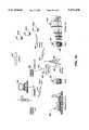
- FIG. 3is a functional block diagram illustrating the architecture of a portable data collection terminal as shown in FIG. 2;
- FIG. 4is diagram of the application program architecture as stored within the ROM of the portable data collection terminal shown in FIG. 3;
- FIG. 5is a flow diagram of the Program Manager program shown in the architecture diagram of FIG. 4;
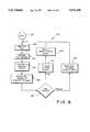
- FIG. 6is a flow diagram of the Transaction Manager program shown in the architecture diagram of FIG. 4;
- FIG. 7is a functional block diagram of the database server shown in FIG. 2;
- FIG. 8is a diagrammatic showing of the architecture of the database server memory
- FIG. 9is a flow diagram of the Presentation Manager program shown in the architecture diagram of FIG. 8;
- FIG. 10is a diagrammatic illustration of an expanded data capture system configured in a manner similar to that of FIG. 2 in a client/server architecture to effect distributed processing between a plurality of portable date collection terminals employing computers for executing programs and a mass storage for storing application programs and/or data to be selectively transmitted under the control of a data base server for use by the computer of a designated terminal, but further including a wide area network to which the mass storage is connected and a mobile access server (MAS) for controlling in response to a call from a determined one of the terminals the flow of application programs and/or data from the mass storage to the determined terminal;
- MASmobile access server
- FIG. 11is a functional block diagram illustrating the architecture of the mobile access server as shown in FIG. 10;
- FIG. 12is a flow diagram of the program executed by a computer included within the mobile access server as shown in FIG. 11;
- FIG. 13is a flow diagram of a subroutine incorporated within the program of FIG. 12 for keeping track of the present location of those determined portable terminals within the system of FIG. 10 which place a call for a further application program or part thereof, and/or data.
- the data capture system 110includes a plurality of portable data collection terminals 112a, b - - - n, which in an illustrative embodiment of this invention may take the form of that terminal RT1100 as manufactured by Norand Corporation.
- Each terminal 112includes, as shown in FIG.3, a radio module 152 which is capable of receiving and transmitting RF signals to a base radio transceiver 114, which may illustratively take the form of that model RB3000 base radio transceiver as manufactured by Norand Corporation.
- the RB3000 base radio transceiver 114is capable of operating at multiple baud rates as described in U.S. Pat. No. 4,910,794.
- the received signalsare transmitted to a database server 130, which in response to the received signals applies signals to the base radio transceiver 114 to be transmitted to a selected one of the plurality of the terminals 112.
- Each message transmitted between one of the terminals 112 and the transceiver 114includes an identification number or ID indicating the originating terminal 112 or its user.
- the database server 130is coupled to a host computer 118.
- the host computer 118may take the form of an IBM 3090 main frame with a DB2 database engine.
- each terminal 112is programmed to compose an SQL request that will cause the database server 130 to return an application program, a memory overlay or application specific data to the requesting terminal 112.
- the host computer 118may also access the database server 130 by generating and transmitting SQL request messages thereto.
- the host computer 118has a database, which is accessible through the database server 130 to respond to the SQL request from one of the terminals 112, supplying to the requesting terminal 112 a computer program, memory overlays or application specific data.
- the host computer 118may illustratively take the form of an IBM 3090 main frame with a DB2 database engine and would have a memory of a capacity many orders greater than that of the terminals 112. Much of the data and software to be used by the terminals 112 need not be stored with in the terminal's memory, but rather may reside in the database of the server 130 or in the memory of the host computer 118.
- the needing terminal 112formulates its SQL request message, transmits that message via the base radio transceiver 14 to be processed by the database server 130, which accesses its database (or the memory of the host computer 118) and retransmits the requested data or programs back to the requesting terminal 112.
- At least two tablesare defined as shown in FIG. 7 in a memory of the database server 130 including a first program table 139 and a second authorization table 141.
- the program table 139keeps track of all of the programs, the overlays and the locations where they are stored in the database of the server 130.
- the programsare typically stored as a "bulk" or "binary" data type.
- the program tablerequires at a minimum the following fields or attributes:
- the first, program table 139 and the second authorization table 141may be established within a hard disk drive 137 of the database server 130.
- the SQL requestincludes an attribute to identify whether a new program or an overlay is to be accessed and sent by the requesting terminal 112, and the address or name of the first program table 139.
- the SQL requestdoes not need to have the address of the requested program or overlay, but accesses the program table 139, which provides an address within the hard disk drive 137 in accordance with the attribute.
- the database server 130in response to the SQL request accesses a particular program or overlay and transmits it back to the requesting terminal 112.
- the second authorization table 141identifies the relationship between a particular user and each of the programs which that user is authorized to access. For example, each user has an ID and the authorization table 141 would list the program names which may be accessed by that particular user ID. Similarly, the SQL includes the ID and an address for the authorization table 141. Thus, the SQL request accesses the authorization table 141 to see if the requesting terminal 112 or its user as identified by the ID is permitted to use a particular program or overlay. If there is a match between the ID and one of the listed programs stored in the authorization table 141, then as will be explained, the database server 130 will access that program or overlay and transmit it back to the requesting terminal 112. On the other hand, if the ID is not found within the authorization table 141, the requested program or overlay is not transmitted back to the requesting terminal 112.
- FIG. 3shows an illustrative embodiment of the hardware architecture of the elements of the portable data collection terminals 112.
- Each terminal 112includes a data bus 142 for interconnecting the element of the terminal 112, which may include a ROM 144 for the bootstrap loader, a flash ROM 150 for storing system and application programs, a static RAM (SRAM) 146 for storing data, programs and dynamically loadable program overlays, a microprocessor 140 which may take the form of that processor made by NEC as a model V25, the radio module 152, a serial communication interface (UART) 148 for the radio module 152, a bar coding scanning interface 149, a manual input system such as a keyboard 113 and a display 115.
- ROM 144for the bootstrap loader
- SRAMstatic RAM
- microprocessor 140which may take the form of that processor made by NEC as a model V25
- the radio module 152the radio module 152
- a serial communication interface (UART) 148for the radio
- the serial communication interface 148permit messages to be transmitted and received via the radio module 152.
- the keyboard 113 and the-bar code scanning interface 149permit data entry respectively by the terminal user and a CCD bar code scanner similar to those identified in FIG. 1 by the numeral 22.
- a scanner 22would be moved across coded data to provide data descriptive of the item to which the bar code was attached, typically including a description of the item, its price and/or other inventory data.
- each terminal 112is battery operated, a plurality of memories 144, 146 and 150 are provided therein to store various types and sizes of data and programs dependent upon their use and to the end, that battery drain be minimized.
- the ROM 144stores the operating system and basic input/output system (BIOS) for the microprocessor 140.
- the SRAM 146stores the dynamically loadable program overlays and data.
- the flash ROM 150stores the system operating program and the application programs to be executed by the microprocessor 140, typically carrying out the various inventory functions for which a terminal 112 may be programmed.
- a portion of the SRAM 146is partitioned into tables for application specific data, i.e., data to be used by the stored application programs.
- the architecture of the software stored in the flash ROM 150is shown in FIG. 4.
- the flash ROM 150stores a plurality of application programs 154, e.g., inventory tracking, a program manager program 156 explained below with respect to FIG. S for transmitting the SQL request to the database server 130 to obtain an overlay module or a new program, a transaction manager 158 as explained below in detail with respect to FIG. 6 for opening a new session to receive or to transmit streams of data thereto, and a radio protocol stack 160 for effecting the RF transmission of a data stream 161a out to the database server 130 and for receiving an RF transmission via a data stream input 161b from the database server 130.
- application programs 154e.g., inventory tracking
- a program manager program 156explained below with respect to FIG. S for transmitting the SQL request to the database server 130 to obtain an overlay module or a new program
- a transaction manager 158as explained below in detail with respect to FIG. 6 for opening a new session to receive or to transmit streams of data thereto
- An application interface 155is established between the application programs 154 and the program manager 156, whereby any of the application programs can request the services of the program manager 156, which may be illustratively thought of as a collection of sub-routine calls for new overlay modules or a new program as will be explained below with respect to FIG. 5.
- the application programs 154have a transaction application programming interface (API) 157 with the transaction manager 158 as will be explained below with respect to FIG. 6.
- the transaction API 157permits an application to transmit a SQL request to the database server 130.
- the transaction manager 158has an interface 159 as exemplified by a NetBIOS with the radio protocol stack 160, which effects by RF transmission the sending and receiving of data to and from the database server 130.
- the radio protocol stack 160is transparent with respect to an application program, i.e., the application program need not be programmed to effect radio transmission but only to place a call to transmit or to receive data.
- Either the program manager 156 or the transaction manager 158carries out that step without any special program of the application programs 154.
- the database server 130may illustratively take the form of an IBM PS/2 model 80 computer running IBM's OS/2 Extended Edition operating system. Generally, the database server 130 responds to a SQL request transmitted by a radio module 152 of a data collection terminal 112 (see FIG. 3), or from the host computer 118. The response of the database server 130 to the SQL request is determined by the semantics of that SQL request, which is formatted in the ANSI standard SQL. The database server 130 need not store state information about each of the terminals 112a, b - - - n.
- Data relating to a particular or specific terminal 112is assigned to its own memory table, which may be illustratively formed at its unique address within a DRAM 136 of the database server 130 as shown in FIG. 7. That table for terminal specific data may be used as a buffer, where the addressed location within the DRAM 1436 acts as a buffer memory to be addressed by a SQL request and in response thereto, to transmit the data stored in that buffer to the requesting terminal 112.
- the terminal specific datacould be stored in the hard disk drive 137 of the database server 130 and could be accessed by assigning an identifier attribute for that data to each terminal 112, whereby the appropriate relation in the hard disk drive 137 of the database server 130 could be defined.
- each SQL requestidentifies a new program, an overlay or application specific data which is required by the requesting terminal 112; the database server 130 responds to that request and transmits in turn the requested program, memory overlay or application specific data to the particular requesting terminal 112.
- FIG. 7shows the hardware architecture of the database server 130, including a data bus 134 for connecting the various elements thereof, a microprocessor 132 illustratively taking the form of that processor manufactured by Intel under its model No. 80386, a ROM 135 for the computer power up program, the diagnostic programs and the BIOS program, the dynamic RAM (DRAM) 136 serving as a memory for a database server program, server data, and a "cache" memory for the database, and a mass storage in the illustrative form of the hard disk drive 137 for storing all of the partitioned application programs and application specific data to be called by the plurality of terminals 112a, b- - - n.
- DRAMdynamic RAM
- the database server 130may provide gateway functions to other databases, e.g., DB2.
- a gateway functionpermits access to a remote database by passing and/or reformatting the request.
- the SQL requestcould be translated into a format that would correspond and be recognized by that format of the remote database.
- the SRAM 146 of a portable data collection terminal 112is significantly smaller than the disk drive 137 of a database server 130 and may have a capacity insufficient to store all of an application program and data to be executed by its microprocessor 140.
- Distributed processingis accomplished in the context of this data capture system 110 employing a plurality of terminals 112 and a database server 130, by partitioning each application program into a plurality of parts or modules.
- the first program partis known as a root module and will be loaded first when a request for a new program is issued by the microprocessor 140 at power up or entered by a user through the terminal's key board 113.
- the root module and the overlay moduleswill be given unique identifiers so that they may be loaded when requested.
- the microprocessor 140When the microprocessor 140 is executing the last instruction of a root module or an overlay module, then it is necessary to request and retrieve the next overlay module to permit the application program to continue to be executed without interruption.
- this data capture system 110is capable of formatting a SQL request for that original program or root module and for the subsequent overlay modules.
- the programmerbuilds into the application program a request to the program manager program 156 (see FIG. 4) to request and load an overlay module and jump to it.
- a program in the development environmentdetermines the external function calls in program and substitutes a call to the program manager program 156.
- the development in partitioning of an application programis accomplished on the database server 130 using a data collection terminal emulator system that emulates the keyboard 113, the display 115 and other possible peripherals of the terminal 112.
- the only programming to be done specific to the database server 130is to create the database tables and load them with any application specific data.
- the software architecture of the DRAM 136 as shown in FIG. 7is further described in FIG. 8, as being partitioned to store a commercial database management system 212 such as the SQL Server (Microsoft), a database gateway 214, e.g., a DB2 Gateway by IBM, a presentation manager 216 to be more fully disclosed in the flow diagram of FIG. 9, a network protocol stack 218, and a radio protocol stack 220.
- a commercial database management system 212such as the SQL Server (Microsoft)
- a database gateway 214e.g., a DB2 Gateway by IBM
- presentation manager 216to be more fully disclosed in the flow diagram of FIG. 9
- a network protocol stack 218, and a radio protocol stack 220e.g., a radio protocol stack 220.
- the program manager program 156generally shown in the software architecture diagram of FIG. 4 is more fully shown in the flow diagram of FIG.5. Basically, the program manager program 156 is disposed in the next lower layer below an application program, e.g., an inventory program, and responds to its request for either a new program or a memory overlay, to configure and transmit an SQL request to the database server 130. Upon receipt of the requested program or memory overlay, the program manager program 156 stores it in SRAM 146 before initiating its execution by the microprocessor 140. A start 162 is initiated in a number of ways by the associated application program. At power up when typically there is no application being executed, the operating system program, which is stored in the ROM 144, places a call to the program manager 156.
- an application programe.g., an inventory program
- a new application programmay be called by the operator by actuating a selected key(s) of the keyboard 113. Appreciating that all of a particular application program need not be stored in the SRAM 146, overlay modules of the application program presently being executed may be stored in the database of the server 130 and may be called by the program manager program 156. The application program continues to be executed until it recognizes that the next step is not available, at which time it places a call through the start step 162 for the next section or overlay module of the application program to be retrieved and placed in the SRAM 146 of the requesting terminal 112.
- step 164determines whether a new program or memory overlay is being requested. If a new program is requested, step 166 accesses the database in the server 130 for the requested program. In particular, step 166 initiates the radio protocol stack program 160, whereby the radio module 152 (see FIG. 3) is activated to transmit the SQL request to the database server 130 via the transceiver 114 (see FIG. 2).
- the SQL request initiated by step 166seeks as will be described below a list of programs which are stored in the database server 130 and is available to this originating terminal 112. Initially, step 166 calls the radio protocol stack program 160 (see FIG. 4), whereby access is made through the UART 148 (see FIG.
- the radio protocol stack 160provides the protocols and media access to allow the SQL request to be sent via the transceiver 114 to the database server 130.
- the radio protocol stack 160would include the RTC system as described in U.S. Pat. No. 4,940,974.
- the radio protocol stack 160is called to initiate transmission, a session is said to be held between the requesting terminal 112 and the database server 130. For example, when a SQL request is generated by the transaction manager 158 (see FIG. 4), a session is opened.
- Each sessionenjoys a logical relationship between the requesting terminal 112 and the database, e.g., the hard disk drive 137, within the database server 130.
- Each sessionincludes one or more data packets, the data packet being the maximum byte size of the data stream appearing on the output 161a that may be transmitted by the radio module 152.
- the radio protocol stack 160functions to segregate a data stream out 161a to be transmitted to the database server 130, into a number of data packets and, in similar fashion, to reassemble the data packets of an incoming data stream appearing at the input 161b into a continuous data stream.
- Each SQL requestincludes an address or ID of its originating terminal 112.
- the database server 130uses a presentation manager program 216 to store the relationship mapping) between the terminal ID and the operating system session identifier, which is stored in a known location within the DRAM 136 of the database server 130. In this way, the database server 130 remembers to which of the plurality of terminals 112a, b - - - n that the requested data or memory overlay, should be transmitted.
- step 166may format an SQL request in the following manner:
- step 168displays the received list of authorized programs on the terminal's display 115.
- step 170 of FIG. 5the terminal user selects from that list of available programs as displayed in step 168 and enters via the terminal keyboard 113 the selected program to be requested from the database of the server 130.
- the transaction manager 158is called to format the SQL request to retrieve from the remote database the particular program selected in step 170.
- An illustrative example of such an SQL requestmay take the form of:
- the SQL requestaccesses the first, program table 139 (see FIG. 7) to obtain the address in the hard disk drive 137 of the requested program, e.g. the "inventory.exe” program, which is an original program or it's root overlay.
- step 174After transmission of the SQL request for a new program, step 174 waits for a returned message to the terminal 112 and will time out after a set period, e.g., 30 seconds. If no response is received by the requesting terminal 112 within this period, step 176 generates a return error message and returns it to the calling application program. On the other hand if the requested original program is received within the period, step 178 updates a mapping memory or table, which may be illustratively included within the SRAM 146 (see FIG. 3) of the terminal 112. A record of the application program or module thereof presently being executed by the microprocessor 140 is recorded in the mapping memory in terms of its starting address and length.
- step 178When a new program is received and loaded into SRAM 146, step 178 records its starting address and length in the mapping memory, before loading the root module of the new program into a designated location of the SRAM 146 and, thereafter, initiates execution of the received and loaded program instead of returning control to the application program.
- the SRAM 146is used as a "cache" memory to receive the 140 programs and memory overlays to be executed by the microprocessor 140.
- the SRAM 146provides a local memory from which the application program may be executed, whereas the remaining sections or memory overlays of the application program and other original programs may be stored distantly in the database of the server 130.
- step 164determines that the application is not requesting a new program, but rather an overlay module
- step 180examines the SRAM 146 and if the requested overlay module is in SRAM 146, the program moves to step 178 to initiate execution of the overlay module and control is passed to the overlay module.
- step 180moves control moves to the transaction manager 158, which formulates and transmits a SQL request via the transceiver 114 to retrieve the needed overlay module from the database of the server 130.
- the requested memory overlayis transmitted back via the transceiver 114 and is loaded into SRAM 146 and, thereafter, the local mapping memory in SRAM 146 is updated in terms of its starting address and length.
- step 178initiates execution of the overlay module before returning control to the application program.
- step 194determines whether the requested data is in the local memory, i.e., SRAM 146, and, if so stored, step 208 returns the local data to be processed by the application program.
- step 196formats an SQL request for the requested data and step 198 calls the radio protocol stack program 160 (see FIG. 4) thus actuating the radio module 152 and transmitting the SQL request via the transceiver 114 to access the requested data in the database of the server 130.
- Step 200waits while the server 130 accesses the requested data and transmits it via the transceiver 114 to the requesting terminal 112.
- Step 200times a response period, e.g., 1 minute, and if that period is exceeded indicating an error condition, step 202 returns an error message to the calling application program.
- step 204formats the requested data in a form usable by the calling application program, before step 206 returns that data to the application program.
- Step 206returns the data to the SRAM 146, whereby control is passed to the application program which uses the returned data.
- the presentation manager program 216processes the SQL request transmitted from one of the terminals 112 (see FIG. 2) via the transceiver 114 and a standard interface, e.g. Unix sockets or IBM NetBIOS, to the database manager program 212 (see FIG. 8).
- the database manager program 212interprets the SQL request and accesses the hard disk drive 137 accordingly (see FIG. 7). This allows an application program being executed by the microprocessor 140 (see FIG. 3) to establish sessions with any SQL accessible database as maybe formed within the hard disk drive 137 of the database server 130.
- the principle function of the presentation manager program 216is to translate between that format used by the transaction manager program 158 of a terminal 112 and the SQL format of the database of the hard disk drive 137, if these formats are different.
- the SQL request to be applied to the database management program 212is semantically configured in accordance with the function to be achieved.
- the SQL requestmay direct that data be inserted into the disk drive 137, that data be accessed and retrieved, that a new program or overlay module be retrieved from the disk drive 137, that data be added to one or more fields in a set of records stored in the disk drive 137 or that data be deleted from one or more records of the disk drive 137. Updating involves the transmitting of new variable values from the originating terminal 112.
- the presentation manager program 216enters through start step 230 to step 232, which waits for a SQL request to be forwarded from the radio protocol stack 220 (see FIG. 8).
- the SQL requestis directed toward the database manager program 212.
- Step 234receives the SQL request as a sequence of bytes.
- Step 236comes into play only if some reformulation of the SQL request is necessary. In a first instance, if the database manager program 212 was not adapted to support the ANSI standard SQL format or if the SQL request was compressed, then step 236 would be necessary to decompress the data or to translate the format of the SQL request into that of the particular database manager program 212 employed in the system.
- step 238provides the data to the database manager program 212 through an interface in the illustrative form of the IBM NetBIOS interface.
- the translation step 236is identical to the formatting request 196 of the transaction manager program 158 of FIG. 6 and, ordinarily, it would be only necessary to perform the formatting or translation step once upon a particular SQL request, preferably in the presentation manager program 216.
- Step 240waits for the database manager program 212 to access the disk drive 137 for a predetermined time period.
- step 242If the requested material, i.e., the application specific data, root overlay or memory overlay, is received within the time period, it is translated in step 242 to the format of the requesting terminal 112, before calling in step 244 the radio protocol stack program 220 to transmit the accessed material back to the requesting terminal 112.
- step 240If the SQL request is one to add or delete data from the hard disk drive 137, step 240 generates a status message indicating that the change of the hard disk drive 137 has been completed, before step 242 translates that status message into the terminal format and the radio protocol stack 220 is called in step 244 to send that message back to the requesting terminal 112. If the time period set in step 240 times out, without receiving the requested material, step 246 transmits an error packet to the radio protocol stack program 220, whereby an error message is returned to the requesting terminal 112.
- a data capture system 110that distributes the application program between the memory of a terminal 112 and a database server 130 serving a plurality of such terminals 112.
- the complexity of the program to be executed upon a terminal 112is minimized by permitting the data base server 130 and its hard disk 137 to store a large variety of application programs to be served to its client terminals 112.
- the above data capture system 110permits dynamic loading of the original programs or root modules and subsequent memory overlays from the hard disk 137, whereby the size of the SRAM 146 of a terminal 112 and the power required by the terminal 112 is minimized. Further, the amount of data transmitted via the RF link between each of the plurality of terminals 112 and the database server 130 is minimized.
- the database server 130provides a "user friendly" environment for the development of application programs for the terminals 112.
- the database server 130is capable of readily developing both the client and server portions of the application programs to be executed by the terminal's microprocessor 140.
- the data capture system 310comprises a plurality of portable data collection terminals 312a, b - - - n, a vehicle 329 for transporting a mobile access server (MAS) 331 as will be described in detail below with respect of FIG. 11, a mass storage as incorporated into an application server 330 and a wide area network 333 to which the application server 330 is connected.
- MASmobile access server
- the purpose of the data capture system 310is similar to that of the system 110.
- the systemconveys data from the data collection terminals 312 as deployed at a remote location in the illustrative form of a warehouse or delivery site 308, to a main information or control center 306.
- the system 310responds to a call from a determined data collection terminal 312 to convey selected portions of a new application program, an application overlay and/or application specific data to the determined, calling terminal 312 for use by a computer incorporated within each of the terminals 312.
- the wide area network 333is illustratively coupled via a bidirectional data/program transmission path, e.g., a leased telephone line 337, to a gateway 339, which in turn is connected to a second bidirectional data/program transmission path in the illustrative form of an ethernet 341.
- the wide area networkis also connected to a long range radio module 347, which in turn is connected to an antenna 335. It is appreciated that any number of antennae 335 and related modules 347 may be also connected to the network, and/or that the wide area network 333 may permit transmission over great distances from each of the antennae to the main information center 306.
- the gateway 339interconnects the transmissions lines 337 and 341. As shown in FIG.
- the ethernet 341is coupled to the application server 330 which incorporates the mass storage, a transceiver 314 and a terminal or remote server 343.
- the remote server 343permits access to the application server via a suitable dial up link such as conventional telephone lines.
- the gateway 339controls or directs the flow of data and/or programs between the leased line 337 and selected of the devices 330, 314 and 343 as may be connected to the ethernet 341. In particular, the gateway 339 functions to address the information flow from the line 337 to selected of the connected devices 330, 314 and 343.
- a first wireless communication capability as identified by the numeral 347exists between the MAS 331 and each of the plurality of data collection terminals 312a, b - - - n.
- a second wireless communication capability as identified by the numeral 349is established between the MAS 331 and the wide area network 335 and, in particular, the antenna 335 connected to one end of the network 335.
- the MAS 331be mobile to permit it to move, e.g., to be transported by the vehicle 329, to any number of sites.
- the data collection system 310in contrast to the system 110 is adapted to collect data at a plurality of sites and from distinct pluralities of terminals 312 as are located at corresponding sites.
- the vehicle 329is capable of transporting its MAS 331 from site to site, whereat the MAS 331 will facilitate the transmission of the collected data from the corresponding set or plurality of data collection terminals 312 to the wide area network 335.
- the vehicle 329may be equipped with docks (not shown) which are coupled by hardwired links to the MAS 331. Such an arrangement would permit the data collection terminals 312 to be brought to the vehicle 329 and loaded into a dock before the collected would be downloaded over the hardwired link to the MAS 331.
- each of the wireless communication capabilities 347, 349 and 351respectively include a single transceiver coupled with and operated under the control of the MAS 331 and a transceiver included within each of the data collection terminals 312a, b - - - n, a transceiver (not shown) as connected with the antenna 335 and the transceiver 314, respectively.
- the wireless communication capabilities 347, 349 and 351are designed to transmit the collected data, the program applications and the application specific data over varying distances.
- the wireless communication capabilities 347 and 351would be designed in terms of power and data rate to transmit over relatively short distances, appreciating that the vehicle 329 would be capable of approaching within 500-1,000 feet of either of the delivery site 308 and the plurality of data collection terminals 312 disposed therein, and the transceiver 314 disposed at the main information center 306.
- the wireless communication capability 349differs from the capabilities 347 and 351 in that it is designed in terms of its power rating and data transmission speed to transmit the information flow over substantially greater distances; such a characteristic permits the MAS 331 to be transported to different delivery sites 308 at significant distances, e.g., 5-30 miles, from the antenna 335 and its radio module 347.
- the transmission distance between the center 306 and the MAS 331may be significantly increased by using utilizing transmission via a satellite 345 from the MAS 331 to the transceiver associated with the antenna 335.
- System of satellites disposed in geosynchronous orbitsare capable of bidirectionally transmitting data between a MAS 331 disposed anywhere in the USA or anywhere in the world, and the main information center 306.
- the MAS 331employs at least two different transceivers or radio modules of different power and data rate specification to permit the transmission of the information flow over these different ranges.
- the DRAM 346is adapted to store the programs controlling the operations of the MAS 331, for example the program as shown in FIG, 12, and any data used by such programs.
- the flash ROM 350is adapted to store the BIOS programs required for the operation of the processor 332.
- the MAS 331includes at least two different types of transceivers or radio modules adapted to transmit the bidirectional data flow over distinct ranges of distance.
- the first transceiver, the wide area radio module 314, and the radio module 347are a part of the wireless communication capacity 349 for transmitting the bidirectional information flow between the MAS 331 and the wide area network 333.
- a serial communication interface (UART) 338interconnects the wide area radio module to the data bus 334.
- the second transceiver, i.e., the radio module 356,is a part of the wireless communication capacity 347 for transmitting the bidirectional information flow between the MAS 331 and each of the plurality of data collection terminals 312.
- a PCMCIA controller 355interconnects the radio module 356 to the data bus 334.
- FIG. 11further illustrates that at least two other data collection terminals 312e and 312g are connected directly to the data bus 334 by a UART 338' and the ethernet 353.
- the high speed data transmission characteristics of the ethernet 353 as compared to those of serial communication interface 338'make it a preferable data link between the MAS 331 and a dock (not shown) for receiving a plurality of the data collection terminals 312.
- the dockwould be permanently mounted on the vehicle 329 thereby permitting the terminals to be securely transported by the vehicle 329, and further to permit downloading of the collected data from the terminals 312 loaded in the dock for transmission to the wide area network 335.
- the flow diagram of FIG. 12illustrates the operation of the MAS 331 as carried out by the processor 332 executing the corresponding control program.
- the MAS 331waits until a call is received from one of the plurality of data collection terminals 312a, b - - - n.
- each callis formatted in the SQL language and further identifies which of the terminals 312 from which it was transmitted.
- the SQL callfurther identifies the information needed to continue the further operation of the identified terminal 312, e.g., a new application program, an overlay and/or application specific data.
- the structure and operation of the terminals 312 in the embodiment of FIGS. 10-14corresponds respectively to the hardware architecture of FIG.
- FIG. 4flash ROM 150
- FIG. 5the memory architecture of FIG. 4 (flash ROM 150), and the program manager program 156 illustrated in FIG. 5 for formulating the SQL call for the next overlay or a new application program and the transaction manager program 158 illustrated in FIG. 6 for formulating the SQL call for application specific data.
- step 402saves in the DRAM 346 the ID of the calling data collection terminal 312, as well an indication of which communication path was used to transmit the received SQL call to the MAS 331.
- the SQL callmay be transmitted to the MAS 331 variously by the radio module 356, or directly from the terminal 312e via the serial communication interface 338' or from the terminal 312g via the ethernet 353.
- the stored communication path indicationidentifies from where the calling terminal 312 is calling and facilitates the transmission of the requested information back to the calling terminal 312.
- step 404it is determined whether the called new program, application overlay or application specific data is locally stored in the MAS 331, i.e., whether the requested information is stored in the mass storage 337. If locally stored, step 416 transmits the requested information back to the calling terminal 312. As will be described below with respect to FIG. 13, step 416 determines where the calling terminal 312 is presently located and selectively actuates one of the radio module 356, ethernet 353 or the serial communication interface 338 to transmit the requested information back to the portable calling terminal 312 at its present location.
- the MAS 331functions as a server to the data collection terminals 312, in a manner similar to the server relationship of the data base server 130 to the plurality of date collection terminals 112a, b - - - n.
- step 406formats a request or SQL call, before step 408 transmits the formulated SQL call from the MAS 331 via the wireless communication capability 349 to the wide area network 335 and, in particular, to the remote or application server 330 which is connected to the wide area network 335 and its ethernet 341 as shown in FIG. 10.
- step 408selectively actuates one of the long range radio module 314 or the short range radio module 356, before transmitting the SQL request to the application server 330 via the actuated radio module.
- the contemplated radio module selectioncould be carried out in different ways. The vehicle operator as he or she is approaching the main information center 306, may enter that indication via a suitable keyed data input device (not shown).
- the transceiver 314 disposed at the main information center 306could continuously transmit a message coded to indicate that it is transmitted from the transceiver 314.
- the MAS 331sets a flag indicating that further communications may be now made via the short range radio 356 to the transceiver 314. It is contemplated that in one illustrative embodiment that steps 406 and 408 would perform functions similar to those carried out by the program manager program 156, the transaction manager program 158 and the radio protocol stack 160 as variously shown in FIGS. 4, 5 and 6.
- the process implemented by the steps 406 and 408functions as a client to the application server 318 in a fashion similar to the client relationship between the plurality of data collection terminal 112a, b - - - n and the data base server 130 as shown in FIG. 2.
- Step 410initiates upon the transmission of the SQL call to the application server 318 the timing of a period in which to receive back from the server 318 the requested new application, application overlay and/or application specific data.
- the application server 330in one illustrative embodiment thereof operates in a manner similar to the database server 130, whose hardware structure, the memory architecture and programming are illustrated respectively in FIGS. 7, 8 and 9. If the requested information is timely received before the period times out, step 414 selectively actuates (in a manner similar to that of step 416 and as will be explained below with respect to FIG.13) one of the long range module 314 and short range module 356 to transmit the requested information to the calling data collection terminal 312. Upon receipt, the calling terminal 312 will continue to operate, using the received information.
- step 412selectively actuates one of the modules 314 or 356 to transmit an error message back to the calling data collection terminal 312 to inform it that the requested information is at least not currently available.
- the response of the calling terminal 312depends on the nature of application currently being run by the calling terminal 312. For example if a particular application can not continue to operate without the requested information, the calling terminal 312 will place calls for that information until it is received. On the other hand if the application can continue to operate without that information, the calling terminal 312 will place a limited number of calls and, if the requested information is not received in response to those calls, then the calling terminal 312 will perform another function or use default information.
- a subroutineis provided to further explain the operation of step 414 or 416.
- the problem solved by the illustrated subroutineis to identify where the calling data collection terminal 312 is presently located and, correspondingly, which link or port serves to presently connect that calling terminal 312 to the MAS 331, i.e., the ethernet 353, the serial communications interface 338' or the radio module 356.
- the MAS 331 in step 422repetitively, e.g., every 2 seconds sends out on all 3 ports a "foreign agent advertisement", i.e., a message that the MAS 331 is presently available as a server to receive its call and to respond by returning the requested information.
- the MAS 331initiates the timing of a period in which a call over any of the three ports of the MAS 331 should be received and listens for a message from a terminal 312 over all of the ports or channels.
- the processor within the data collecting terminal 312is programmed to transmit a registration message, which indicates that the transmitting terminal 312 is responding to a received available message as was generated earlier by the MAS 331 in step 422; the terminal's processor is also programmed to generate an advertisement solicitation or request to generate the "foreign agent advertisement" or available message. If that period set in step 423 times out without receiving any message, a return is made to step 422 prompting a further "advertisement" to be transmitted.
- step 424examines the received message and, if the received signal is a registration message, then step 426 will update the indication stored within the DRAM 346 as to which port has been enabled to transmit information from the MAS 331 to the calling terminal 312. On the other hand if the received message is an advertisement request or solicitation, the subroutine will return to step 422 to again transmit a "foreign agent advertisement.”
- the MAS 331knows the current port by which to transmit the called information to the calling terminal 312, even if the link may have changed between the time when the terminal originally transmitted its call for information to the MAS 331 and the time that collected information is transmitted back to the calling terminal 312.
- the changing of the linkmay oft occur when the size of the requested data and, consequently, the transmission times from the MAS 331 to the calling terminal 312 are large. Noting that typical transmission times for a single packet of data, i.e., 500 bytes, is in the order of 5 seconds, the transmission time of an overlay of 35K bytes would require five minutes and a new application of 0.5 Megabytes would be approximately 11/2 hours.
Landscapes
- Engineering & Computer Science (AREA)
- Computer Networks & Wireless Communication (AREA)
- Signal Processing (AREA)
- Quality & Reliability (AREA)
- Software Systems (AREA)
- General Engineering & Computer Science (AREA)
- Theoretical Computer Science (AREA)
- Physics & Mathematics (AREA)
- General Physics & Mathematics (AREA)
- Computer And Data Communications (AREA)
- Mobile Radio Communication Systems (AREA)
Abstract
Description
______________________________________ attribute type description ______________________________________ program char Name of the program name overlay char root or other named overlay date char or date Date program was created (revision control) program varbinary or The actual program or overlay varchar size integer The size of the binary to be loaded ______________________________________
Claims (28)
Priority Applications (3)
| Application Number | Priority Date | Filing Date | Title |
|---|---|---|---|
| US08/520,136US5671436A (en) | 1991-08-21 | 1995-08-28 | Versatile RF data capture system |
| US08/935,741US6112206A (en) | 1991-08-21 | 1997-09-23 | Data collection and dissemination system |
| US10/779,136US20040162889A1 (en) | 1991-08-21 | 2004-02-13 | Distributed application and data dissemination system |
Applications Claiming Priority (3)
| Application Number | Priority Date | Filing Date | Title |
|---|---|---|---|
| US07/748,150US5349678A (en) | 1991-08-21 | 1991-08-21 | Versatile RF data capture system |
| US08/267,758US5568645A (en) | 1991-08-21 | 1994-07-05 | Versatile RF data capture system |
| US08/520,136US5671436A (en) | 1991-08-21 | 1995-08-28 | Versatile RF data capture system |
Related Parent Applications (1)
| Application Number | Title | Priority Date | Filing Date |
|---|---|---|---|
| US08/267,758Continuation-In-PartUS5568645A (en) | 1989-01-31 | 1994-07-05 | Versatile RF data capture system |
Related Child Applications (1)
| Application Number | Title | Priority Date | Filing Date |
|---|---|---|---|
| US08/935,741ContinuationUS6112206A (en) | 1991-08-21 | 1997-09-23 | Data collection and dissemination system |
Publications (1)
| Publication Number | Publication Date |
|---|---|
| US5671436Atrue US5671436A (en) | 1997-09-23 |
Family
ID=46250720
Family Applications (2)
| Application Number | Title | Priority Date | Filing Date |
|---|---|---|---|
| US08/520,136Expired - LifetimeUS5671436A (en) | 1991-08-21 | 1995-08-28 | Versatile RF data capture system |
| US08/935,741Expired - Fee RelatedUS6112206A (en) | 1991-08-21 | 1997-09-23 | Data collection and dissemination system |
Family Applications After (1)
| Application Number | Title | Priority Date | Filing Date |
|---|---|---|---|
| US08/935,741Expired - Fee RelatedUS6112206A (en) | 1991-08-21 | 1997-09-23 | Data collection and dissemination system |
Country Status (1)
| Country | Link |
|---|---|
| US (2) | US5671436A (en) |
Cited By (101)
| Publication number | Priority date | Publication date | Assignee | Title |
|---|---|---|---|---|
| US5758151A (en)* | 1994-12-09 | 1998-05-26 | Storage Technology Corporation | Serial data storage for multiple access demand |
| US5761500A (en)* | 1996-04-18 | 1998-06-02 | Mci Communications Corp. | Multi-site data communications network database partitioned by network elements |
| US5842210A (en)* | 1996-10-30 | 1998-11-24 | Motorola, Inc. | Method and apparatus for selectively retrieving data from a database in a data communication system |
| DE19801576A1 (en)* | 1998-01-19 | 1999-07-22 | Deutsche Telekom Mobil | Terminal-supported menu guidance for value added service |
| US6084528A (en)* | 1996-09-05 | 2000-07-04 | Symbol Technologies, Inc. | Intranet scanning terminal system |
| WO2001003009A1 (en)* | 1999-07-02 | 2001-01-11 | Toptier, Israel, Ltd. | Relation path viability prediction |
| US20020002039A1 (en)* | 1998-06-12 | 2002-01-03 | Safi Qureshey | Network-enabled audio device |
| US6338045B1 (en) | 1998-01-20 | 2002-01-08 | John Charalambos Pappas | Apparatus for and method of managing and tracking activities and parts |
| US20020033843A1 (en)* | 2000-05-05 | 2002-03-21 | Loos Michael T. | System and method for mobile software application development and deployment |
| US20020073240A1 (en)* | 2000-11-27 | 2002-06-13 | Heikki Kokkinen | Server |
| US20020163592A1 (en)* | 2001-04-18 | 2002-11-07 | Eiji Ueda | Portable terminal, overlay output method, and program therefor |
| EP1219123A4 (en)* | 1999-09-01 | 2003-01-02 | Weblink Wireless Inc | Controlling an end-user application among a plurality of communication units |
| US6523028B1 (en)* | 1998-12-03 | 2003-02-18 | Lockhead Martin Corporation | Method and system for universal querying of distributed databases |
| US20030046451A1 (en)* | 1997-03-07 | 2003-03-06 | Mobile Information System, Inc. | System and method for mobile data processing and transmission |
| WO2002017652A3 (en)* | 2000-08-22 | 2003-10-16 | Symbian Ltd | Database for use with a wireless information device |
| US6694359B1 (en) | 1991-08-21 | 2004-02-17 | Unova, Inc. | Data collection and dissemination system |
| US6754468B1 (en)* | 1998-05-02 | 2004-06-22 | Micronas Intermetall Gmbh | Local communications device |
| US20040229654A1 (en)* | 2003-05-12 | 2004-11-18 | Jp Mobile Operating L.P. | Mobile application builder |
| US20040249833A1 (en)* | 2001-06-25 | 2004-12-09 | Kenneth Oksanen | Copying method and system for copying cells in a database |
| US6856605B1 (en) | 1998-09-01 | 2005-02-15 | Metrocall, Inc. | System and method for controlling an end-user application among a plurality of communication units in a wireless messaging network |
| US6898591B1 (en)* | 1997-11-05 | 2005-05-24 | Billy Gayle Moon | Method and apparatus for server responding to query to obtain information from second database wherein the server parses information to eliminate irrelevant information in updating databases |
| US20050149564A1 (en)* | 2004-01-07 | 2005-07-07 | Nokia Corporation | Remote management and access of databases, services and devices associated with a mobile terminal |
| US20050164704A1 (en)* | 2004-01-23 | 2005-07-28 | Winsor Gerald W. | User profile service |
| US7231380B1 (en)* | 1999-10-09 | 2007-06-12 | Innovaport Llc | Apparatus and method for providing products location information to customers in a store |
| US20070174538A1 (en)* | 2004-02-19 | 2007-07-26 | Telefonaktiebolaget Lm Ericsson (Publ) | Method and arrangement for state memory management |
| US20080043676A1 (en)* | 1998-05-29 | 2008-02-21 | Research In Motion Limited | System and Method for Redirecting Data to a Wireless Device Over a Plurality of Communication Paths |
| US20080154712A1 (en)* | 2006-12-13 | 2008-06-26 | Crown Equipment Corporation | Fleet management system |
| US20080201131A1 (en)* | 2007-02-15 | 2008-08-21 | Gautam Kar | Method and apparatus for automatically discovering features in free form heterogeneous data |
| US7483417B2 (en) | 1996-04-18 | 2009-01-27 | Verizon Services Corp. | Telephony communication via varied redundant networks |
| US7506097B2 (en) | 2001-09-25 | 2009-03-17 | Caterpillar, Inc. | Method and apparatus for installing data in a memory on a work machine |
| US7574480B1 (en)* | 1999-04-26 | 2009-08-11 | Nokia Corporation | Radio terminal |
| US20090210140A1 (en)* | 1997-04-09 | 2009-08-20 | Short Iii Charles F | Database method and system for conducting integrated dispatching |
| US7603360B2 (en) | 2005-09-14 | 2009-10-13 | Jumptap, Inc. | Location influenced search results |
| US7660581B2 (en) | 2005-09-14 | 2010-02-09 | Jumptap, Inc. | Managing sponsored content based on usage history |
| US7664097B2 (en) | 1996-04-18 | 2010-02-16 | Verizon Services Corp. | Telephone service via networking |
| US20100039247A1 (en)* | 2006-12-13 | 2010-02-18 | Ziegler Ronald L | Impact sensing usable with fleet management system |
| US7676394B2 (en) | 2005-09-14 | 2010-03-09 | Jumptap, Inc. | Dynamic bidding and expected value |
| US7702318B2 (en) | 2005-09-14 | 2010-04-20 | Jumptap, Inc. | Presentation of sponsored content based on mobile transaction event |
| US7739361B2 (en) | 1996-08-20 | 2010-06-15 | Thibault Richard L | Methods for remote process control with networked digital data processors and a virtual machine environment |
| US7752209B2 (en) | 2005-09-14 | 2010-07-06 | Jumptap, Inc. | Presenting sponsored content on a mobile communication facility |
| US7769764B2 (en) | 2005-09-14 | 2010-08-03 | Jumptap, Inc. | Mobile advertisement syndication |
| US20100228428A1 (en)* | 2006-12-13 | 2010-09-09 | Crown Equipment Corporation | Information system for industrial vehicles |
| US7813332B1 (en) | 1997-03-19 | 2010-10-12 | Verizon Services Corp. | Voice call alternative routing through PSTN and internet networks |
| US7817619B1 (en) | 1996-12-18 | 2010-10-19 | Verizon Services Corp. | Internet long distance telephone service |
| US7830860B2 (en) | 1997-03-11 | 2010-11-09 | Verizon Services Corp. | Packet data network voice call quality monitoring |
| US7860871B2 (en) | 2005-09-14 | 2010-12-28 | Jumptap, Inc. | User history influenced search results |
| US20110022442A1 (en)* | 2006-12-13 | 2011-01-27 | Crown Equipment Corporation | Information system for industrial vehicles including cyclical recurring vehicle information message |
| US20110040440A1 (en)* | 2009-08-12 | 2011-02-17 | Crown Equipment Corporation | Information system for industrial vehicles |
| US7912458B2 (en) | 2005-09-14 | 2011-03-22 | Jumptap, Inc. | Interaction analysis and prioritization of mobile content |
| US7948968B2 (en) | 1997-09-16 | 2011-05-24 | Verizon Communications Inc. | Network session management |
| US8028275B2 (en) | 1999-05-17 | 2011-09-27 | Invensys Systems, Inc. | Control systems and methods with smart blocks |
| US8027879B2 (en) | 2005-11-05 | 2011-09-27 | Jumptap, Inc. | Exclusivity bidding for mobile sponsored content |
| US8090452B2 (en) | 1999-06-11 | 2012-01-03 | Invensys Systems, Inc. | Methods and apparatus for control using control devices that provide a virtual machine environment and that communicate via an IP network |
| US8103545B2 (en) | 2005-09-14 | 2012-01-24 | Jumptap, Inc. | Managing payment for sponsored content presented to mobile communication facilities |
| US8127060B2 (en) | 2009-05-29 | 2012-02-28 | Invensys Systems, Inc | Methods and apparatus for control configuration with control objects that are fieldbus protocol-aware |
| US8131271B2 (en) | 2005-11-05 | 2012-03-06 | Jumptap, Inc. | Categorization of a mobile user profile based on browse behavior |
| US20120059696A1 (en)* | 2010-09-08 | 2012-03-08 | United Video Properties, Inc. | Systems and methods for providing advertisements to user devices using an advertisement gateway |
| US8156128B2 (en) | 2005-09-14 | 2012-04-10 | Jumptap, Inc. | Contextual mobile content placement on a mobile communication facility |
| US8175585B2 (en) | 2005-11-05 | 2012-05-08 | Jumptap, Inc. | System for targeting advertising content to a plurality of mobile communication facilities |
| US8195133B2 (en) | 2005-09-14 | 2012-06-05 | Jumptap, Inc. | Mobile dynamic advertisement creation and placement |
| US8209344B2 (en) | 2005-09-14 | 2012-06-26 | Jumptap, Inc. | Embedding sponsored content in mobile applications |
| US8229914B2 (en) | 2005-09-14 | 2012-07-24 | Jumptap, Inc. | Mobile content spidering and compatibility determination |
| US8238888B2 (en) | 2006-09-13 | 2012-08-07 | Jumptap, Inc. | Methods and systems for mobile coupon placement |
| US8290810B2 (en) | 2005-09-14 | 2012-10-16 | Jumptap, Inc. | Realtime surveying within mobile sponsored content |
| US8302030B2 (en) | 2005-09-14 | 2012-10-30 | Jumptap, Inc. | Management of multiple advertising inventories using a monetization platform |
| US8311888B2 (en) | 2005-09-14 | 2012-11-13 | Jumptap, Inc. | Revenue models associated with syndication of a behavioral profile using a monetization platform |
| US8364540B2 (en) | 2005-09-14 | 2013-01-29 | Jumptap, Inc. | Contextual targeting of content using a monetization platform |
| US8364521B2 (en) | 2005-09-14 | 2013-01-29 | Jumptap, Inc. | Rendering targeted advertisement on mobile communication facilities |
| US8368640B2 (en) | 1999-05-17 | 2013-02-05 | Invensys Systems, Inc. | Process control configuration system with connection validation and configuration |
| US8433297B2 (en) | 2005-11-05 | 2013-04-30 | Jumptag, Inc. | System for targeting advertising content to a plurality of mobile communication facilities |
| US8463964B2 (en) | 2009-05-29 | 2013-06-11 | Invensys Systems, Inc. | Methods and apparatus for control configuration with enhanced change-tracking |
| US8503995B2 (en) | 2005-09-14 | 2013-08-06 | Jumptap, Inc. | Mobile dynamic advertisement creation and placement |
| US8571999B2 (en) | 2005-11-14 | 2013-10-29 | C. S. Lee Crawford | Method of conducting operations for a social network application including activity list generation |
| US8590013B2 (en) | 2002-02-25 | 2013-11-19 | C. S. Lee Crawford | Method of managing and communicating data pertaining to software applications for processor-based devices comprising wireless communication circuitry |
| US8594814B2 (en) | 2008-06-20 | 2013-11-26 | Invensys Systems, Inc. | Systems and methods for immersive interaction with actual and/or simulated facilities for process, environmental and industrial control |
| US8615719B2 (en) | 2005-09-14 | 2013-12-24 | Jumptap, Inc. | Managing sponsored content for delivery to mobile communication facilities |
| US8660891B2 (en) | 2005-11-01 | 2014-02-25 | Millennial Media | Interactive mobile advertisement banners |
| US8666376B2 (en) | 2005-09-14 | 2014-03-04 | Millennial Media | Location based mobile shopping affinity program |
| US8688671B2 (en) | 2005-09-14 | 2014-04-01 | Millennial Media | Managing sponsored content based on geographic region |
| US8745682B1 (en) | 2000-03-13 | 2014-06-03 | Broadcom Corporation | Integrated cable modem and cable television management system |
| US8805339B2 (en) | 2005-09-14 | 2014-08-12 | Millennial Media, Inc. | Categorization of a mobile user profile based on browse and viewing behavior |
| US8812526B2 (en) | 2005-09-14 | 2014-08-19 | Millennial Media, Inc. | Mobile content cross-inventory yield optimization |
| US8819659B2 (en) | 2005-09-14 | 2014-08-26 | Millennial Media, Inc. | Mobile search service instant activation |
| US8832100B2 (en) | 2005-09-14 | 2014-09-09 | Millennial Media, Inc. | User transaction history influenced search results |
| US8938062B2 (en) | 1995-12-11 | 2015-01-20 | Comcast Ip Holdings I, Llc | Method for accessing service resource items that are for use in a telecommunications system |
| US8989718B2 (en) | 2005-09-14 | 2015-03-24 | Millennial Media, Inc. | Idle screen advertising |
| US8996587B2 (en) | 2007-02-15 | 2015-03-31 | International Business Machines Corporation | Method and apparatus for automatically structuring free form hetergeneous data |
| US9058406B2 (en) | 2005-09-14 | 2015-06-16 | Millennial Media, Inc. | Management of multiple advertising inventories using a monetization platform |
| US9076175B2 (en) | 2005-09-14 | 2015-07-07 | Millennial Media, Inc. | Mobile comparison shopping |
| US9191505B2 (en) | 2009-05-28 | 2015-11-17 | Comcast Cable Communications, Llc | Stateful home phone service |
| US9201979B2 (en) | 2005-09-14 | 2015-12-01 | Millennial Media, Inc. | Syndication of a behavioral profile associated with an availability condition using a monetization platform |
| US9223878B2 (en) | 2005-09-14 | 2015-12-29 | Millenial Media, Inc. | User characteristic influenced search results |
| US9471925B2 (en) | 2005-09-14 | 2016-10-18 | Millennial Media Llc | Increasing mobile interactivity |
| US9516370B1 (en) | 2004-05-05 | 2016-12-06 | Black Hills Media, Llc | Method, device, and system for directing a wireless speaker from a mobile phone to receive and render a playlist from a content server on the internet |
| US9703892B2 (en) | 2005-09-14 | 2017-07-11 | Millennial Media Llc | Predictive text completion for a mobile communication facility |
| US10038756B2 (en) | 2005-09-14 | 2018-07-31 | Millenial Media LLC | Managing sponsored content based on device characteristics |
| US10592930B2 (en) | 2005-09-14 | 2020-03-17 | Millenial Media, LLC | Syndication of a behavioral profile using a monetization platform |
| US10803482B2 (en) | 2005-09-14 | 2020-10-13 | Verizon Media Inc. | Exclusivity bidding for mobile sponsored content |
| US10911894B2 (en) | 2005-09-14 | 2021-02-02 | Verizon Media Inc. | Use of dynamic content generation parameters based on previous performance of those parameters |
| US11225404B2 (en) | 2006-12-13 | 2022-01-18 | Crown Equipment Corporation | Information system for industrial vehicles |
| US12380373B2 (en) | 2009-09-01 | 2025-08-05 | Crown Equipment Corporation | Information system for industrial vehicles including cyclical recurring vehicle information message |
Families Citing this family (68)
| Publication number | Priority date | Publication date | Assignee | Title |
|---|---|---|---|---|
| US6169789B1 (en)* | 1996-12-16 | 2001-01-02 | Sanjay K. Rao | Intelligent keyboard system |
| US6591288B1 (en)* | 1998-05-19 | 2003-07-08 | Nortel Networks Limited | Data network accelerated access system |
| US6148414A (en)* | 1998-09-24 | 2000-11-14 | Seek Systems, Inc. | Methods and systems for implementing shared disk array management functions |
| US6398105B2 (en)* | 1999-01-29 | 2002-06-04 | Intermec Ip Corporation | Automatic data collection device that intelligently switches data based on data type |
| US7266706B2 (en)* | 1999-03-03 | 2007-09-04 | Yottayotta, Inc. | Methods and systems for implementing shared disk array management functions |
| GB9909275D0 (en)* | 1999-04-23 | 1999-06-16 | Philips Electronics Nv | Reconfigurable communications network |
| IL148130A0 (en)* | 1999-08-16 | 2002-09-12 | Force Corp Z | System of reusable software parts and methods of use |
| US6687745B1 (en) | 1999-09-14 | 2004-02-03 | Droplet, Inc | System and method for delivering a graphical user interface of remote applications over a thin bandwidth connection |
| US7062446B1 (en)* | 1999-11-16 | 2006-06-13 | Dana Corporation | Apparatus and method for tracking and managing physical assets |
| US20050131729A1 (en)* | 1999-11-16 | 2005-06-16 | Melby John M. | Apparatus and method for tracking and managing physical assets |
| US6952680B1 (en) | 1999-11-16 | 2005-10-04 | Dana Corporation | Apparatus and method for tracking and managing physical assets |
| US20020077944A1 (en)* | 1999-11-16 | 2002-06-20 | Bly J. Aaron | System and method for disposing of assets |
| US20020082966A1 (en)* | 1999-11-16 | 2002-06-27 | Dana Commercial Credit Corporation | System and method for benchmarking asset characteristics |
| AU2592701A (en)* | 1999-12-23 | 2001-07-03 | My-E-Surveys.Com, Llc | System and methods for internet commerce and communication based on customer interaction and preferences |
| AU2001234758A1 (en)* | 2000-02-04 | 2001-08-14 | America Online Incorporated | High performance "freeze-dried" dynamic web page generation |
| US6519773B1 (en) | 2000-02-08 | 2003-02-11 | Sherjil Ahmed | Method and apparatus for a digitized CATV network for bundled services |
| CA2404095A1 (en)* | 2000-03-22 | 2001-09-27 | Yottayotta, Inc. | Method and system for providing multimedia information on demand over wide area networks |
| US6834285B1 (en) | 2000-03-24 | 2004-12-21 | Numoda Corporation | Computer system for portable digital data capture and data distribution |
| AU2001251104A1 (en)* | 2000-03-30 | 2001-10-15 | Qualcomm Incorporated | Method and apparatus for a mobile station application to identify specified events |
| FI20001514A0 (en)* | 2000-06-26 | 2000-06-26 | Nokia Mobile Phones Ltd | Electronic system |
| US20020022961A1 (en)* | 2000-08-15 | 2002-02-21 | Stefan Sepanaho | Displaying information on a portable digital device by transmission of a universal resource locator over a short-range radio frequency link |
| US7149511B1 (en)* | 2000-08-31 | 2006-12-12 | Rosetta-Wireless Corporation | Wireless intelligent personal server |
| US7155517B1 (en)* | 2000-09-28 | 2006-12-26 | Nokia Corporation | System and method for communicating reference information via a wireless terminal |
| WO2002041165A1 (en)* | 2000-11-14 | 2002-05-23 | Joseph Kozikowski | Time independent, data conferencing system |
| US7080076B1 (en) | 2000-11-28 | 2006-07-18 | Attenex Corporation | System and method for efficiently drafting a legal document using an authenticated clause table |
| KR20010044238A (en)* | 2001-01-19 | 2001-06-05 | 김양환 | Mobil data storage using wireless network |
| GB2372904B (en)* | 2001-03-02 | 2004-09-08 | Nokia Mobile Phones Ltd | Electronic transactions |
| US20020127969A1 (en)* | 2001-03-12 | 2002-09-12 | Meade William Kendall | Wireless network storage device and method |
| US7237017B1 (en) | 2001-03-13 | 2007-06-26 | Panamsat Corporation | Micronode in a satellite based content delivery system |
| US7130908B1 (en) | 2001-03-13 | 2006-10-31 | Intelsat Ltd. | Forward cache management between edge nodes in a satellite based content delivery system |
| US7174373B1 (en) | 2001-03-13 | 2007-02-06 | Panamsat Corporation | Self-contained demonstration node in a satellite based content delivery system |
| US7154898B1 (en) | 2001-03-13 | 2006-12-26 | Intelsat, Ltd. | Scalable edge node |
| KR100464973B1 (en)* | 2001-06-15 | 2005-01-05 | 엘지전자 주식회사 | Method of sharing mutually a data for mobile phone users |
| TW515955B (en)* | 2001-08-30 | 2003-01-01 | Inventec Corp | Authorized data reading method and system thereof |
| US7233960B1 (en) | 2001-10-31 | 2007-06-19 | Numoda Corporation | System and method for mobile wireless electronic data capture and distribution of a merchant card-processing application |
| US20050114285A1 (en)* | 2001-11-16 | 2005-05-26 | Cincotta Frank A. | Data replication system and method |
| US7370077B2 (en)* | 2001-11-21 | 2008-05-06 | Hewlett-Packard Development Company, L.P. | Dynamic generation of a networked information resource |
| US20060053075A1 (en)* | 2001-11-26 | 2006-03-09 | Aaron Roth | System and method for tracking asset usage and performance |
| US20030120956A1 (en)* | 2001-12-20 | 2003-06-26 | Inventec Corporation | Authorization method and system for storing and retrieving data |
| US7599983B2 (en) | 2002-06-18 | 2009-10-06 | Wireless Ink Corporation | Method, apparatus and system for management of information content for enhanced accessibility over wireless communication networks |
| WO2004004236A2 (en)* | 2002-06-27 | 2004-01-08 | Snap-On Incorporated | Portal for distributing business and product information |
| CA2436439A1 (en)* | 2002-08-02 | 2004-02-02 | Retrieval Dynamics Corporation | Remote database access apparatus, method and computer program product |
| US7386601B2 (en)* | 2002-08-28 | 2008-06-10 | Casio Computer Co., Ltd. | Collected data providing apparatus and portable terminal for data collection |
| KR20040022060A (en)* | 2002-09-06 | 2004-03-11 | 엘지전자 주식회사 | Multi-function wireless memory pack |
| US7185006B2 (en)* | 2002-09-23 | 2007-02-27 | Hewlett-Packard Development Company, L.P. | Method and apparatus for reducing the scope of queries that seek information from networked computers |
| US7472135B2 (en)* | 2002-10-18 | 2008-12-30 | Nokia Corporation | Method and system for recalling details regarding past events |
| WO2004044756A1 (en)* | 2002-11-14 | 2004-05-27 | Mobidata Group Pty Limited | System and method relating to remotely accessible securely stored data files |
| US7565688B2 (en)* | 2002-12-23 | 2009-07-21 | Hewlett-Packard Development Company, L.P. | Network demonstration techniques |
| US7363053B2 (en)* | 2003-03-28 | 2008-04-22 | Lockheed Martin Corproation | System for integrated mobile devices |
| WO2004102323A2 (en)* | 2003-05-06 | 2004-11-25 | Dana Corporation | System or method for analyzing information organized in a configurable manner |
| US20050037787A1 (en)* | 2003-06-27 | 2005-02-17 | Rosett-Wireless Corporation | Wireless intelligent portable-server system (WIPSS) |
| US20050058112A1 (en)* | 2003-09-15 | 2005-03-17 | Sony Corporation | Method of and apparatus for adaptively managing connectivity for mobile devices through available interfaces |
| US20050125614A1 (en)* | 2003-12-09 | 2005-06-09 | Royer Robert J.Jr. | Adaptive layout cache organization to enable optimal cache hardware performance |
| US20050149363A1 (en)* | 2004-01-07 | 2005-07-07 | Jonathan Loiterman | Data collection and process control system |
| KR100689746B1 (en) | 2005-02-16 | 2007-03-08 | 주식회사 부강샘스 | Wireless hard disk drive |
| JP4598642B2 (en)* | 2005-10-05 | 2010-12-15 | クラリオン株式会社 | Navigation system, license management apparatus, license management system, license acquisition method, and license acquisition program |
| US7756829B2 (en)* | 2006-04-18 | 2010-07-13 | Sandeep Bhanote | Method and apparatus for mobile data collection and management |
| US20080016183A1 (en)* | 2006-07-17 | 2008-01-17 | Pi-Hui Wang | Library database simultaneous link re-inquiry system and operation method of the re-inquiry system |
| CN100442896C (en)* | 2006-08-02 | 2008-12-10 | 华为技术有限公司 | System and method for realizing wireless terminal data information storage |
| SG140493A1 (en)* | 2006-08-24 | 2008-03-28 | Yokogawa Engineering Asia Pte | Behaviour based safety observation system and method |
| US7849139B2 (en) | 2007-05-02 | 2010-12-07 | Ouri Wolfson | Adaptive search in mobile peer-to-peer databases |
| US8183994B2 (en)* | 2007-09-18 | 2012-05-22 | Los Alamos National Security, Llc | Flexible, scalable, service-oriented surveillance system architecture |
| US9002344B2 (en)* | 2007-12-05 | 2015-04-07 | Microsoft Technology Licensing, Llc | Phone content service |
| US8818992B2 (en) | 2008-09-12 | 2014-08-26 | Nokia Corporation | Method, system, and apparatus for arranging content search results |
| US20100070482A1 (en)* | 2008-09-12 | 2010-03-18 | Murali-Krishna Punaganti Venkata | Method, system, and apparatus for content search on a device |
| NO332765B1 (en)* | 2009-05-13 | 2013-01-07 | Moota Telecom As | Procedure for custom updating and downloading software to a mobile communication device without user interaction |
| US11379594B2 (en)* | 2020-01-20 | 2022-07-05 | International Business Machines Corporation | Media obfuscation |
| US11310311B2 (en) | 2020-01-20 | 2022-04-19 | International Business Machines Corporation | Media obfuscation |
Citations (11)
| Publication number | Priority date | Publication date | Assignee | Title |
|---|---|---|---|---|
| US3942157A (en)* | 1974-01-22 | 1976-03-02 | Azurdata Inc. | Data gathering formatting and transmitting system having portable data collecting device |
| US4125871A (en)* | 1975-08-11 | 1978-11-14 | Arthur D. Little, Inc. | Portable data entry device |
| US4277837A (en)* | 1977-12-30 | 1981-07-07 | International Business Machines Corporation | Personal portable terminal for financial transactions |
| US4821291A (en)* | 1986-09-22 | 1989-04-11 | Stevens John K | Improvements in or relating to signal communication systems |
| US4839854A (en)* | 1985-09-13 | 1989-06-13 | Seiko Instruments & Electronics Ltd. | Data collection system having stationary unit with electromagnetic induction circuitry for bidirectionally relaying data |
| US4905186A (en)* | 1982-04-06 | 1990-02-27 | Sharp Kabushiki Kaisha | Portable data terminal |
| US4910794A (en)* | 1988-08-04 | 1990-03-20 | Norand Corporation | Mobile radio data communication system and method |
| US4924462A (en)* | 1988-11-01 | 1990-05-08 | Norand Corporation | Multiterminal communication system and method |
| US4940974A (en)* | 1988-11-01 | 1990-07-10 | Norand Corporation | Multiterminal communication system and method |
| US5054112A (en)* | 1988-03-16 | 1991-10-01 | Seiko Instruments Inc. | Electronic data collection system |
| US5218187A (en)* | 1990-01-18 | 1993-06-08 | Norand Corporation | Hand-held data capture system with interchangeable modules |
- 1995
- 1995-08-28USUS08/520,136patent/US5671436A/ennot_activeExpired - Lifetime
- 1997
- 1997-09-23USUS08/935,741patent/US6112206A/ennot_activeExpired - Fee Related
Patent Citations (11)
| Publication number | Priority date | Publication date | Assignee | Title |
|---|---|---|---|---|
| US3942157A (en)* | 1974-01-22 | 1976-03-02 | Azurdata Inc. | Data gathering formatting and transmitting system having portable data collecting device |
| US4125871A (en)* | 1975-08-11 | 1978-11-14 | Arthur D. Little, Inc. | Portable data entry device |
| US4277837A (en)* | 1977-12-30 | 1981-07-07 | International Business Machines Corporation | Personal portable terminal for financial transactions |
| US4905186A (en)* | 1982-04-06 | 1990-02-27 | Sharp Kabushiki Kaisha | Portable data terminal |
| US4839854A (en)* | 1985-09-13 | 1989-06-13 | Seiko Instruments & Electronics Ltd. | Data collection system having stationary unit with electromagnetic induction circuitry for bidirectionally relaying data |
| US4821291A (en)* | 1986-09-22 | 1989-04-11 | Stevens John K | Improvements in or relating to signal communication systems |
| US5054112A (en)* | 1988-03-16 | 1991-10-01 | Seiko Instruments Inc. | Electronic data collection system |
| US4910794A (en)* | 1988-08-04 | 1990-03-20 | Norand Corporation | Mobile radio data communication system and method |
| US4924462A (en)* | 1988-11-01 | 1990-05-08 | Norand Corporation | Multiterminal communication system and method |
| US4940974A (en)* | 1988-11-01 | 1990-07-10 | Norand Corporation | Multiterminal communication system and method |
| US5218187A (en)* | 1990-01-18 | 1993-06-08 | Norand Corporation | Hand-held data capture system with interchangeable modules |
Cited By (223)
| Publication number | Priority date | Publication date | Assignee | Title |
|---|---|---|---|---|
| US6694359B1 (en) | 1991-08-21 | 2004-02-17 | Unova, Inc. | Data collection and dissemination system |
| US20040162889A1 (en)* | 1991-08-21 | 2004-08-19 | Morris Michael D. | Distributed application and data dissemination system |
| US5758151A (en)* | 1994-12-09 | 1998-05-26 | Storage Technology Corporation | Serial data storage for multiple access demand |
| US8938062B2 (en) | 1995-12-11 | 2015-01-20 | Comcast Ip Holdings I, Llc | Method for accessing service resource items that are for use in a telecommunications system |
| US5761500A (en)* | 1996-04-18 | 1998-06-02 | Mci Communications Corp. | Multi-site data communications network database partitioned by network elements |
| US7664097B2 (en) | 1996-04-18 | 2010-02-16 | Verizon Services Corp. | Telephone service via networking |
| US7483417B2 (en) | 1996-04-18 | 2009-01-27 | Verizon Services Corp. | Telephony communication via varied redundant networks |
| US8379531B2 (en) | 1996-04-18 | 2013-02-19 | Verizon Services Corp. | Telephony communication via varied redundant networks |
| US8553681B2 (en) | 1996-06-26 | 2013-10-08 | Verizon Services Corp. | Telephone service via packet-switched networking |
| US7882197B2 (en) | 1996-08-20 | 2011-02-01 | Invensys Systems, Inc. | Control system methods that transfer control apparatus information over IP networks in web page-less transfers |
| US7899070B2 (en) | 1996-08-20 | 2011-03-01 | Invensys Systems, Inc. | Control system apparatus with change updates |
| US8023500B2 (en) | 1996-08-20 | 2011-09-20 | Invensys Systems, Inc. | Methods for process control with change updates |
| US8081584B2 (en) | 1996-08-20 | 2011-12-20 | Invensys Systems, Inc. | Control system apparatus and systems using value-based transfers |
| US7739361B2 (en) | 1996-08-20 | 2010-06-15 | Thibault Richard L | Methods for remote process control with networked digital data processors and a virtual machine environment |
| US7979488B2 (en) | 1996-08-20 | 2011-07-12 | Invensys Systems, Inc. | Control system methods using value-based transfers |
| US6084528A (en)* | 1996-09-05 | 2000-07-04 | Symbol Technologies, Inc. | Intranet scanning terminal system |
| US5842210A (en)* | 1996-10-30 | 1998-11-24 | Motorola, Inc. | Method and apparatus for selectively retrieving data from a database in a data communication system |
| US7817619B1 (en) | 1996-12-18 | 2010-10-19 | Verizon Services Corp. | Internet long distance telephone service |
| US6889139B2 (en) | 1997-03-07 | 2005-05-03 | Sidewinder Holdings Ltd. | System and method for mobile data processing and transmission |
| US20030046451A1 (en)* | 1997-03-07 | 2003-03-06 | Mobile Information System, Inc. | System and method for mobile data processing and transmission |
| US7830860B2 (en) | 1997-03-11 | 2010-11-09 | Verizon Services Corp. | Packet data network voice call quality monitoring |
| US7813332B1 (en) | 1997-03-19 | 2010-10-12 | Verizon Services Corp. | Voice call alternative routing through PSTN and internet networks |
| US20090210140A1 (en)* | 1997-04-09 | 2009-08-20 | Short Iii Charles F | Database method and system for conducting integrated dispatching |
| US9215254B1 (en) | 1997-09-16 | 2015-12-15 | Verizon Patent And Licensing Inc. | Network session management for telephony over hybrid networks |
| US8976782B1 (en) | 1997-09-16 | 2015-03-10 | Verizon Patent And Licensing Inc. | Network session management for telephony over hybrid networks |
| US7948968B2 (en) | 1997-09-16 | 2011-05-24 | Verizon Communications Inc. | Network session management |
| US6898591B1 (en)* | 1997-11-05 | 2005-05-24 | Billy Gayle Moon | Method and apparatus for server responding to query to obtain information from second database wherein the server parses information to eliminate irrelevant information in updating databases |
| DE19801576C2 (en)* | 1998-01-19 | 2002-04-11 | Deutsche Telekom Mobil | Process for terminal-supported menu navigation in mobile communication systems |
| DE19801576A1 (en)* | 1998-01-19 | 1999-07-22 | Deutsche Telekom Mobil | Terminal-supported menu guidance for value added service |
| US6338045B1 (en) | 1998-01-20 | 2002-01-08 | John Charalambos Pappas | Apparatus for and method of managing and tracking activities and parts |
| US9552188B1 (en) | 1998-01-22 | 2017-01-24 | Black Hills Media, Llc | Method and device for displaying supplemental information while rendering a playlist |
| US8755763B2 (en) | 1998-01-22 | 2014-06-17 | Black Hills Media | Method and device for an internet radio capable of obtaining playlist content from a content server |
| US20070089135A1 (en)* | 1998-01-22 | 2007-04-19 | Concert Technology Corporation | Network-enabled audio device |
| US9312827B2 (en) | 1998-01-22 | 2016-04-12 | Black Hills Media, Llc | Network enabled audio device and radio site |
| US9397627B2 (en) | 1998-01-22 | 2016-07-19 | Black Hills Media, Llc | Network-enabled audio device |
| US8918480B2 (en) | 1998-01-22 | 2014-12-23 | Black Hills Media, Llc | Method, system, and device for the distribution of internet radio content |
| US9549001B1 (en) | 1998-01-22 | 2017-01-17 | Black Hills Media, Llc | Method and device for sourcing and constructing a playlist |
| US8050652B2 (en) | 1998-01-22 | 2011-11-01 | Horsham Enterprises, Llc | Method and device for an internet radio capable of obtaining playlist content from a content server |
| US8792850B2 (en) | 1998-01-22 | 2014-07-29 | Black Hills Media | Method and device for obtaining playlist content over a network |
| US20070089132A1 (en)* | 1998-01-22 | 2007-04-19 | Concert Technology Corporation | Network-enabled audio device |
| US8045952B2 (en) | 1998-01-22 | 2011-10-25 | Horsham Enterprises, Llc | Method and device for obtaining playlist content over a network |
| US6754468B1 (en)* | 1998-05-02 | 2004-06-22 | Micronas Intermetall Gmbh | Local communications device |
| US20080043676A1 (en)* | 1998-05-29 | 2008-02-21 | Research In Motion Limited | System and Method for Redirecting Data to a Wireless Device Over a Plurality of Communication Paths |
| US8949456B2 (en)* | 1998-05-29 | 2015-02-03 | Blackberry Limited | System and method for redirecting data to a wireless device over a plurality of communication paths |
| US20020002039A1 (en)* | 1998-06-12 | 2002-01-03 | Safi Qureshey | Network-enabled audio device |
| US6856605B1 (en) | 1998-09-01 | 2005-02-15 | Metrocall, Inc. | System and method for controlling an end-user application among a plurality of communication units in a wireless messaging network |
| US6523028B1 (en)* | 1998-12-03 | 2003-02-18 | Lockhead Martin Corporation | Method and system for universal querying of distributed databases |
| US7574480B1 (en)* | 1999-04-26 | 2009-08-11 | Nokia Corporation | Radio terminal |
| US8028275B2 (en) | 1999-05-17 | 2011-09-27 | Invensys Systems, Inc. | Control systems and methods with smart blocks |
| US8368640B2 (en) | 1999-05-17 | 2013-02-05 | Invensys Systems, Inc. | Process control configuration system with connection validation and configuration |
| US8225271B2 (en) | 1999-05-17 | 2012-07-17 | Invensys Systems, Inc. | Apparatus for control systems with objects that are associated with live data |
| US8229579B2 (en) | 1999-05-17 | 2012-07-24 | Invensys Systems, Inc. | Control systems and methods with versioning |
| US8028272B2 (en) | 1999-05-17 | 2011-09-27 | Invensys Systems, Inc. | Control system configurator and methods with edit selection |
| US8090452B2 (en) | 1999-06-11 | 2012-01-03 | Invensys Systems, Inc. | Methods and apparatus for control using control devices that provide a virtual machine environment and that communicate via an IP network |
| USRE45752E1 (en) | 1999-07-02 | 2015-10-13 | Sap Portals Israel, Ltd. | Relation path viability prediction |
| WO2001003009A1 (en)* | 1999-07-02 | 2001-01-11 | Toptier, Israel, Ltd. | Relation path viability prediction |
| US6502094B1 (en) | 1999-07-02 | 2002-12-31 | Sap Portals, Inc. | Relation path viability prediction |
| EP1219123A4 (en)* | 1999-09-01 | 2003-01-02 | Weblink Wireless Inc | Controlling an end-user application among a plurality of communication units |
| US9990670B1 (en) | 1999-10-09 | 2018-06-05 | Innovaport Llc | Apparatus and method for providing product location information to customers in a store |
| US7819315B1 (en)* | 1999-10-09 | 2010-10-26 | Innovaport Llc | Apparatus and method for providing product location information to customers in a store |
| US9489690B1 (en)* | 1999-10-09 | 2016-11-08 | Innovaport Llc | Apparatus and method for providing product location information to customers in a store |
| US8775260B1 (en)* | 1999-10-09 | 2014-07-08 | Innovaport Llc | Apparatus and method for providing product location information to customers in a store |
| US8787933B1 (en)* | 1999-10-09 | 2014-07-22 | Innovaport Llc | Apparatus and method for providing product location information to customers in a store |
| US7231380B1 (en)* | 1999-10-09 | 2007-06-12 | Innovaport Llc | Apparatus and method for providing products location information to customers in a store |
| US8745682B1 (en) | 2000-03-13 | 2014-06-03 | Broadcom Corporation | Integrated cable modem and cable television management system |
| US20090183138A1 (en)* | 2000-05-05 | 2009-07-16 | @Hand Corporation | System and method for mobile software application development and deployment |
| US7313782B2 (en) | 2000-05-05 | 2007-12-25 | @Hand Corporation | Method for distributing, integrating, and hosting a software platform |
| US20020033843A1 (en)* | 2000-05-05 | 2002-03-21 | Loos Michael T. | System and method for mobile software application development and deployment |
| US20020116698A1 (en)* | 2000-05-05 | 2002-08-22 | Marc Lurie | Method for distributing, integrating, and hosting a software platform |
| US20020057803A1 (en)* | 2000-05-05 | 2002-05-16 | Loos Michael T. | System and method for communicating in a mobile domain across non-persistent data links |
| US7331035B2 (en)* | 2000-05-05 | 2008-02-12 | @ Hand Corporation | System and method for mobile software application development and deployment |
| WO2002017652A3 (en)* | 2000-08-22 | 2003-10-16 | Symbian Ltd | Database for use with a wireless information device |
| US10067739B2 (en) | 2000-11-08 | 2018-09-04 | Black Hills Media, Llc | Unitary electronic speaker device for receiving digital audio data and rendering the digital audio data |
| US9369101B2 (en) | 2000-11-08 | 2016-06-14 | Black Hills Media, Llc | Unitary electronic speaker device for receiving an assignment of a playlist from a home personal computer and rendering the playlist |
| US20020073240A1 (en)* | 2000-11-27 | 2002-06-13 | Heikki Kokkinen | Server |
| US7519740B2 (en) | 2000-11-27 | 2009-04-14 | Nokia Siemens Networks Oy | Server |
| US7193635B2 (en)* | 2001-04-18 | 2007-03-20 | Matsushita Electric Industrial Co., Ltd. | Portable terminal, overlay output method, and program therefor |
| US20020163592A1 (en)* | 2001-04-18 | 2002-11-07 | Eiji Ueda | Portable terminal, overlay output method, and program therefor |
| US20040249833A1 (en)* | 2001-06-25 | 2004-12-09 | Kenneth Oksanen | Copying method and system for copying cells in a database |
| US7506097B2 (en) | 2001-09-25 | 2009-03-17 | Caterpillar, Inc. | Method and apparatus for installing data in a memory on a work machine |
| US8590013B2 (en) | 2002-02-25 | 2013-11-19 | C. S. Lee Crawford | Method of managing and communicating data pertaining to software applications for processor-based devices comprising wireless communication circuitry |
| US7184801B2 (en)* | 2003-05-12 | 2007-02-27 | Good Technology, Inc. | Mobile application builder |
| US20040229654A1 (en)* | 2003-05-12 | 2004-11-18 | Jp Mobile Operating L.P. | Mobile application builder |
| US20050149564A1 (en)* | 2004-01-07 | 2005-07-07 | Nokia Corporation | Remote management and access of databases, services and devices associated with a mobile terminal |
| US8996454B2 (en)* | 2004-01-07 | 2015-03-31 | Nokia Corporation | Remote management and access of databases, services and devices associated with a mobile terminal |
| US20050164704A1 (en)* | 2004-01-23 | 2005-07-28 | Winsor Gerald W. | User profile service |
| US8554876B2 (en) | 2004-01-23 | 2013-10-08 | Hewlett-Packard Development Company, L.P. | User profile service |
| US20070174538A1 (en)* | 2004-02-19 | 2007-07-26 | Telefonaktiebolaget Lm Ericsson (Publ) | Method and arrangement for state memory management |
| US9092319B2 (en) | 2004-02-19 | 2015-07-28 | Telefonaktiebolaget Lm Ericsson (Publ) | State memory management, wherein state memory is managed by dividing state memory into portions each portion assigned for storing state information associated with a specific message class |
| US9554405B2 (en) | 2004-05-05 | 2017-01-24 | Black Hills Media, Llc | Wireless speaker for receiving from a mobile phone directions to receive and render a playlist from a content server on the internet |
| US9516370B1 (en) | 2004-05-05 | 2016-12-06 | Black Hills Media, Llc | Method, device, and system for directing a wireless speaker from a mobile phone to receive and render a playlist from a content server on the internet |
| US8351933B2 (en) | 2005-09-14 | 2013-01-08 | Jumptap, Inc. | Managing sponsored content based on usage history |
| US8041717B2 (en) | 2005-09-14 | 2011-10-18 | Jumptap, Inc. | Mobile advertisement syndication |
| US8195513B2 (en) | 2005-09-14 | 2012-06-05 | Jumptap, Inc. | Managing payment for sponsored content presented to mobile communication facilities |
| US8195133B2 (en) | 2005-09-14 | 2012-06-05 | Jumptap, Inc. | Mobile dynamic advertisement creation and placement |
| US8200205B2 (en) | 2005-09-14 | 2012-06-12 | Jumptap, Inc. | Interaction analysis and prioritzation of mobile content |
| US8209344B2 (en) | 2005-09-14 | 2012-06-26 | Jumptap, Inc. | Embedding sponsored content in mobile applications |
| US10911894B2 (en) | 2005-09-14 | 2021-02-02 | Verizon Media Inc. | Use of dynamic content generation parameters based on previous performance of those parameters |
| US8156128B2 (en) | 2005-09-14 | 2012-04-10 | Jumptap, Inc. | Contextual mobile content placement on a mobile communication facility |
| US8229914B2 (en) | 2005-09-14 | 2012-07-24 | Jumptap, Inc. | Mobile content spidering and compatibility determination |
| US10803482B2 (en) | 2005-09-14 | 2020-10-13 | Verizon Media Inc. | Exclusivity bidding for mobile sponsored content |
| US10592930B2 (en) | 2005-09-14 | 2020-03-17 | Millenial Media, LLC | Syndication of a behavioral profile using a monetization platform |
| US8270955B2 (en) | 2005-09-14 | 2012-09-18 | Jumptap, Inc. | Presentation of sponsored content on mobile device based on transaction event |
| US8290810B2 (en) | 2005-09-14 | 2012-10-16 | Jumptap, Inc. | Realtime surveying within mobile sponsored content |
| US8296184B2 (en) | 2005-09-14 | 2012-10-23 | Jumptap, Inc. | Managing payment for sponsored content presented to mobile communication facilities |
| US8302030B2 (en) | 2005-09-14 | 2012-10-30 | Jumptap, Inc. | Management of multiple advertising inventories using a monetization platform |
| US8311888B2 (en) | 2005-09-14 | 2012-11-13 | Jumptap, Inc. | Revenue models associated with syndication of a behavioral profile using a monetization platform |
| US8316031B2 (en) | 2005-09-14 | 2012-11-20 | Jumptap, Inc. | System for targeting advertising content to a plurality of mobile communication facilities |
| US8332397B2 (en) | 2005-09-14 | 2012-12-11 | Jumptap, Inc. | Presenting sponsored content on a mobile communication facility |
| US8340666B2 (en) | 2005-09-14 | 2012-12-25 | Jumptap, Inc. | Managing sponsored content based on usage history |
| US10038756B2 (en) | 2005-09-14 | 2018-07-31 | Millenial Media LLC | Managing sponsored content based on device characteristics |
| US8359019B2 (en) | 2005-09-14 | 2013-01-22 | Jumptap, Inc. | Interaction analysis and prioritization of mobile content |
| US8364540B2 (en) | 2005-09-14 | 2013-01-29 | Jumptap, Inc. | Contextual targeting of content using a monetization platform |
| US8364521B2 (en) | 2005-09-14 | 2013-01-29 | Jumptap, Inc. | Rendering targeted advertisement on mobile communication facilities |
| US9811589B2 (en) | 2005-09-14 | 2017-11-07 | Millennial Media Llc | Presentation of search results to mobile devices based on television viewing history |
| US9785975B2 (en) | 2005-09-14 | 2017-10-10 | Millennial Media Llc | Dynamic bidding and expected value |
| US9754287B2 (en) | 2005-09-14 | 2017-09-05 | Millenial Media LLC | System for targeting advertising content to a plurality of mobile communication facilities |
| US8457607B2 (en) | 2005-09-14 | 2013-06-04 | Jumptap, Inc. | System for targeting advertising content to a plurality of mobile communication facilities |
| US8463249B2 (en) | 2005-09-14 | 2013-06-11 | Jumptap, Inc. | System for targeting advertising content to a plurality of mobile communication facilities |
| US9703892B2 (en) | 2005-09-14 | 2017-07-11 | Millennial Media Llc | Predictive text completion for a mobile communication facility |
| US8467774B2 (en) | 2005-09-14 | 2013-06-18 | Jumptap, Inc. | System for targeting advertising content to a plurality of mobile communication facilities |
| US8484234B2 (en) | 2005-09-14 | 2013-07-09 | Jumptab, Inc. | Embedding sponsored content in mobile applications |
| US8483671B2 (en) | 2005-09-14 | 2013-07-09 | Jumptap, Inc. | System for targeting advertising content to a plurality of mobile communication facilities |
| US8483674B2 (en) | 2005-09-14 | 2013-07-09 | Jumptap, Inc. | Presentation of sponsored content on mobile device based on transaction event |
| US8489077B2 (en) | 2005-09-14 | 2013-07-16 | Jumptap, Inc. | System for targeting advertising content to a plurality of mobile communication facilities |
| US8494500B2 (en) | 2005-09-14 | 2013-07-23 | Jumptap, Inc. | System for targeting advertising content to a plurality of mobile communication facilities |
| US8503995B2 (en) | 2005-09-14 | 2013-08-06 | Jumptap, Inc. | Mobile dynamic advertisement creation and placement |
| US7603360B2 (en) | 2005-09-14 | 2009-10-13 | Jumptap, Inc. | Location influenced search results |
| US8515401B2 (en) | 2005-09-14 | 2013-08-20 | Jumptap, Inc. | System for targeting advertising content to a plurality of mobile communication facilities |
| US8515400B2 (en) | 2005-09-14 | 2013-08-20 | Jumptap, Inc. | System for targeting advertising content to a plurality of mobile communication facilities |
| US8532634B2 (en) | 2005-09-14 | 2013-09-10 | Jumptap, Inc. | System for targeting advertising content to a plurality of mobile communication facilities |
| US8532633B2 (en) | 2005-09-14 | 2013-09-10 | Jumptap, Inc. | System for targeting advertising content to a plurality of mobile communication facilities |
| US8538812B2 (en) | 2005-09-14 | 2013-09-17 | Jumptap, Inc. | Managing payment for sponsored content presented to mobile communication facilities |
| US7660581B2 (en) | 2005-09-14 | 2010-02-09 | Jumptap, Inc. | Managing sponsored content based on usage history |
| US8554192B2 (en) | 2005-09-14 | 2013-10-08 | Jumptap, Inc. | Interaction analysis and prioritization of mobile content |
| US8103545B2 (en) | 2005-09-14 | 2012-01-24 | Jumptap, Inc. | Managing payment for sponsored content presented to mobile communication facilities |
| US8560537B2 (en) | 2005-09-14 | 2013-10-15 | Jumptap, Inc. | Mobile advertisement syndication |
| US7676394B2 (en) | 2005-09-14 | 2010-03-09 | Jumptap, Inc. | Dynamic bidding and expected value |
| US8583089B2 (en) | 2005-09-14 | 2013-11-12 | Jumptap, Inc. | Presentation of sponsored content on mobile device based on transaction event |
| US9471925B2 (en) | 2005-09-14 | 2016-10-18 | Millennial Media Llc | Increasing mobile interactivity |
| US8099434B2 (en) | 2005-09-14 | 2012-01-17 | Jumptap, Inc. | Presenting sponsored content on a mobile communication facility |
| US9454772B2 (en) | 2005-09-14 | 2016-09-27 | Millennial Media Inc. | Interaction analysis and prioritization of mobile content |
| US8615719B2 (en) | 2005-09-14 | 2013-12-24 | Jumptap, Inc. | Managing sponsored content for delivery to mobile communication facilities |
| US8620285B2 (en) | 2005-09-14 | 2013-12-31 | Millennial Media | Methods and systems for mobile coupon placement |
| US8626736B2 (en) | 2005-09-14 | 2014-01-07 | Millennial Media | System for targeting advertising content to a plurality of mobile communication facilities |
| US8631018B2 (en) | 2005-09-14 | 2014-01-14 | Millennial Media | Presenting sponsored content on a mobile communication facility |
| US8655891B2 (en) | 2005-09-14 | 2014-02-18 | Millennial Media | System for targeting advertising content to a plurality of mobile communication facilities |
| US7702318B2 (en) | 2005-09-14 | 2010-04-20 | Jumptap, Inc. | Presentation of sponsored content based on mobile transaction event |
| US8666376B2 (en) | 2005-09-14 | 2014-03-04 | Millennial Media | Location based mobile shopping affinity program |
| US8688088B2 (en) | 2005-09-14 | 2014-04-01 | Millennial Media | System for targeting advertising content to a plurality of mobile communication facilities |
| US8688671B2 (en) | 2005-09-14 | 2014-04-01 | Millennial Media | Managing sponsored content based on geographic region |
| US9390436B2 (en) | 2005-09-14 | 2016-07-12 | Millennial Media, Inc. | System for targeting advertising content to a plurality of mobile communication facilities |
| US9386150B2 (en) | 2005-09-14 | 2016-07-05 | Millennia Media, Inc. | Presentation of sponsored content on mobile device based on transaction event |
| US8050675B2 (en) | 2005-09-14 | 2011-11-01 | Jumptap, Inc. | Managing sponsored content based on usage history |
| US8768319B2 (en) | 2005-09-14 | 2014-07-01 | Millennial Media, Inc. | Presentation of sponsored content on mobile device based on transaction event |
| US8774777B2 (en) | 2005-09-14 | 2014-07-08 | Millennial Media, Inc. | System for targeting advertising content to a plurality of mobile communication facilities |
| US8180332B2 (en) | 2005-09-14 | 2012-05-15 | Jumptap, Inc. | System for targeting advertising content to a plurality of mobile communication facilities |
| US9384500B2 (en) | 2005-09-14 | 2016-07-05 | Millennial Media, Inc. | System for targeting advertising content to a plurality of mobile communication facilities |
| US7970389B2 (en) | 2005-09-14 | 2011-06-28 | Jumptap, Inc. | Presentation of sponsored content based on mobile transaction event |
| US8798592B2 (en) | 2005-09-14 | 2014-08-05 | Jumptap, Inc. | System for targeting advertising content to a plurality of mobile communication facilities |
| US8805339B2 (en) | 2005-09-14 | 2014-08-12 | Millennial Media, Inc. | Categorization of a mobile user profile based on browse and viewing behavior |
| US8812526B2 (en) | 2005-09-14 | 2014-08-19 | Millennial Media, Inc. | Mobile content cross-inventory yield optimization |
| US8819659B2 (en) | 2005-09-14 | 2014-08-26 | Millennial Media, Inc. | Mobile search service instant activation |
| US8832100B2 (en) | 2005-09-14 | 2014-09-09 | Millennial Media, Inc. | User transaction history influenced search results |
| US8843396B2 (en) | 2005-09-14 | 2014-09-23 | Millennial Media, Inc. | Managing payment for sponsored content presented to mobile communication facilities |
| US8843395B2 (en) | 2005-09-14 | 2014-09-23 | Millennial Media, Inc. | Dynamic bidding and expected value |
| US7912458B2 (en) | 2005-09-14 | 2011-03-22 | Jumptap, Inc. | Interaction analysis and prioritization of mobile content |
| US7907940B2 (en) | 2005-09-14 | 2011-03-15 | Jumptap, Inc. | Presentation of sponsored content based on mobile transaction event |
| US7899455B2 (en) | 2005-09-14 | 2011-03-01 | Jumptap, Inc. | Managing sponsored content based on usage history |
| US8958779B2 (en) | 2005-09-14 | 2015-02-17 | Millennial Media, Inc. | Mobile dynamic advertisement creation and placement |
| US7752209B2 (en) | 2005-09-14 | 2010-07-06 | Jumptap, Inc. | Presenting sponsored content on a mobile communication facility |
| US8989718B2 (en) | 2005-09-14 | 2015-03-24 | Millennial Media, Inc. | Idle screen advertising |
| US7769764B2 (en) | 2005-09-14 | 2010-08-03 | Jumptap, Inc. | Mobile advertisement syndication |
| US8995968B2 (en) | 2005-09-14 | 2015-03-31 | Millennial Media, Inc. | System for targeting advertising content to a plurality of mobile communication facilities |
| US8995973B2 (en) | 2005-09-14 | 2015-03-31 | Millennial Media, Inc. | System for targeting advertising content to a plurality of mobile communication facilities |
| US9271023B2 (en) | 2005-09-14 | 2016-02-23 | Millennial Media, Inc. | Presentation of search results to mobile devices based on television viewing history |
| US9058406B2 (en) | 2005-09-14 | 2015-06-16 | Millennial Media, Inc. | Management of multiple advertising inventories using a monetization platform |
| US9076175B2 (en) | 2005-09-14 | 2015-07-07 | Millennial Media, Inc. | Mobile comparison shopping |
| US7865187B2 (en) | 2005-09-14 | 2011-01-04 | Jumptap, Inc. | Managing sponsored content based on usage history |
| US9110996B2 (en) | 2005-09-14 | 2015-08-18 | Millennial Media, Inc. | System for targeting advertising content to a plurality of mobile communication facilities |
| US9223878B2 (en) | 2005-09-14 | 2015-12-29 | Millenial Media, Inc. | User characteristic influenced search results |
| US9201979B2 (en) | 2005-09-14 | 2015-12-01 | Millennial Media, Inc. | Syndication of a behavioral profile associated with an availability condition using a monetization platform |
| US9195993B2 (en) | 2005-09-14 | 2015-11-24 | Millennial Media, Inc. | Mobile advertisement syndication |
| US7860871B2 (en) | 2005-09-14 | 2010-12-28 | Jumptap, Inc. | User history influenced search results |
| US8660891B2 (en) | 2005-11-01 | 2014-02-25 | Millennial Media | Interactive mobile advertisement banners |
| US8175585B2 (en) | 2005-11-05 | 2012-05-08 | Jumptap, Inc. | System for targeting advertising content to a plurality of mobile communication facilities |
| US8131271B2 (en) | 2005-11-05 | 2012-03-06 | Jumptap, Inc. | Categorization of a mobile user profile based on browse behavior |
| US8433297B2 (en) | 2005-11-05 | 2013-04-30 | Jumptag, Inc. | System for targeting advertising content to a plurality of mobile communication facilities |
| US8027879B2 (en) | 2005-11-05 | 2011-09-27 | Jumptap, Inc. | Exclusivity bidding for mobile sponsored content |
| US8509750B2 (en) | 2005-11-05 | 2013-08-13 | Jumptap, Inc. | System for targeting advertising content to a plurality of mobile communication facilities |
| US9147201B2 (en) | 2005-11-14 | 2015-09-29 | C. S. Lee Crawford | Method of conducting social network application operations |
| US9129303B2 (en) | 2005-11-14 | 2015-09-08 | C. S. Lee Crawford | Method of conducting social network application operations |
| US9129304B2 (en) | 2005-11-14 | 2015-09-08 | C. S. Lee Crawford | Method of conducting social network application operations |
| US8571999B2 (en) | 2005-11-14 | 2013-10-29 | C. S. Lee Crawford | Method of conducting operations for a social network application including activity list generation |
| US8238888B2 (en) | 2006-09-13 | 2012-08-07 | Jumptap, Inc. | Methods and systems for mobile coupon placement |
| US20080154712A1 (en)* | 2006-12-13 | 2008-06-26 | Crown Equipment Corporation | Fleet management system |
| US10599160B2 (en) | 2006-12-13 | 2020-03-24 | Crown Equipment Corporation | Fleet management system |
| US12210353B2 (en) | 2006-12-13 | 2025-01-28 | Crown Equipment Corporation | Fleet management system |
| US11947361B2 (en) | 2006-12-13 | 2024-04-02 | Crown Equipment Corporation | Fleet management system |
| US20100039247A1 (en)* | 2006-12-13 | 2010-02-18 | Ziegler Ronald L | Impact sensing usable with fleet management system |
| US11823502B2 (en) | 2006-12-13 | 2023-11-21 | Crown Equipment Corporation | Impact sensing usable with fleet management system |
| US8060400B2 (en) | 2006-12-13 | 2011-11-15 | Crown Equipment Corporation | Fleet management system |
| US11225404B2 (en) | 2006-12-13 | 2022-01-18 | Crown Equipment Corporation | Information system for industrial vehicles |
| US20100228428A1 (en)* | 2006-12-13 | 2010-09-09 | Crown Equipment Corporation | Information system for industrial vehicles |
| US10810521B2 (en) | 2006-12-13 | 2020-10-20 | Crown Equipment Corporation | Information system for industrial vehicles including cyclical recurring vehicle information message |
| US20110022442A1 (en)* | 2006-12-13 | 2011-01-27 | Crown Equipment Corporation | Information system for industrial vehicles including cyclical recurring vehicle information message |
| US10600256B2 (en) | 2006-12-13 | 2020-03-24 | Crown Equipment Corporation | Impact sensing usable with fleet management system |
| US9984341B2 (en) | 2006-12-13 | 2018-05-29 | Crown Equipment Corporation | Information system for industrial vehicles including cyclical recurring vehicle information message |
| US20080154691A1 (en)* | 2006-12-13 | 2008-06-26 | Wellman Timothy A | Fleet management system |
| US10013815B2 (en) | 2006-12-13 | 2018-07-03 | Crown Equipment Corporation | Information system for industrial vehicles |
| US8249910B2 (en) | 2006-12-13 | 2012-08-21 | Crown Equipment Corporation | Fleet management system |
| US8996587B2 (en) | 2007-02-15 | 2015-03-31 | International Business Machines Corporation | Method and apparatus for automatically structuring free form hetergeneous data |
| US20080201131A1 (en)* | 2007-02-15 | 2008-08-21 | Gautam Kar | Method and apparatus for automatically discovering features in free form heterogeneous data |
| US8108413B2 (en)* | 2007-02-15 | 2012-01-31 | International Business Machines Corporation | Method and apparatus for automatically discovering features in free form heterogeneous data |
| US8594814B2 (en) | 2008-06-20 | 2013-11-26 | Invensys Systems, Inc. | Systems and methods for immersive interaction with actual and/or simulated facilities for process, environmental and industrial control |
| US9191505B2 (en) | 2009-05-28 | 2015-11-17 | Comcast Cable Communications, Llc | Stateful home phone service |
| US8127060B2 (en) | 2009-05-29 | 2012-02-28 | Invensys Systems, Inc | Methods and apparatus for control configuration with control objects that are fieldbus protocol-aware |
| US8463964B2 (en) | 2009-05-29 | 2013-06-11 | Invensys Systems, Inc. | Methods and apparatus for control configuration with enhanced change-tracking |
| US20110040440A1 (en)* | 2009-08-12 | 2011-02-17 | Crown Equipment Corporation | Information system for industrial vehicles |
| US8725345B2 (en) | 2009-08-12 | 2014-05-13 | Crown Equipment Corporation | Information system for industrial vehicles |
| US8583314B2 (en) | 2009-08-12 | 2013-11-12 | Crown Equipment Corporation | Information system for industrial vehicles |
| US12380373B2 (en) | 2009-09-01 | 2025-08-05 | Crown Equipment Corporation | Information system for industrial vehicles including cyclical recurring vehicle information message |
| US20120059696A1 (en)* | 2010-09-08 | 2012-03-08 | United Video Properties, Inc. | Systems and methods for providing advertisements to user devices using an advertisement gateway |
Also Published As
| Publication number | Publication date |
|---|---|
| US6112206A (en) | 2000-08-29 |
Similar Documents
| Publication | Publication Date | Title |
|---|---|---|
| US5671436A (en) | Versatile RF data capture system | |
| US6694359B1 (en) | Data collection and dissemination system | |
| US5568645A (en) | Versatile RF data capture system | |
| US6430409B1 (en) | Method and architecture for an interactive two-way data communication network | |
| US5136716A (en) | Session control in network for digital data processing system which supports multiple transfer protocols | |
| US7617325B2 (en) | Protocol conversion using facilities and utilities | |
| US6421716B1 (en) | System for generating context-sensitive hierarchically ordered document service menus | |
| EP0779759B1 (en) | A method and architecture for an interactive two-way data communication network | |
| AU648113B2 (en) | Apparatus and method for providing decoupling of data exchange details for providing high performance communication between software processes | |
| CN1244064C (en) | Communication terminal with browser and system including such terminal | |
| WO2001069888A1 (en) | System, method, and apparatus for automatically and dynamically updating options, features, and/or services available to a client device | |
| JPH11103305A (en) | Data communication network and method for accessing data file | |
| US6349202B1 (en) | Method of storing and transmitting markup language documents in a mobile radio communications system | |
| CA2284063A1 (en) | System and method for selection and retrieval of diverse types of video data on a computer network | |
| US20080141238A1 (en) | Feature manager system for facilitating communication and shared functionality among components | |
| EP1102191A2 (en) | Method and apparatus for reconciling data between devices | |
| AU769963B2 (en) | Remote saving method of the search information on the Internet | |
| US5913027A (en) | Data processing method for a computer system including computers connected via a communication path to each other and computer-readable recording media for use with the computers | |
| CN1156781C (en) | Radio terminal with browser | |
| US6907456B2 (en) | Default portal site access with wireless module | |
| US20050171734A1 (en) | Electronic data collection system and method | |
| WO2001069382A9 (en) | System, method and apparatus for initial configuration of a client device | |
| KR20030026011A (en) | Asymmetric On-Line/Off-Line Searching and Sending System for Mobile | |
| JP2002358255A (en) | Method of converting bar code into url, and system | |
| KR20020032717A (en) | Advertisement and additional service system using a wireless internet and the method therefor |
Legal Events
| Date | Code | Title | Description |
|---|---|---|---|
| AS | Assignment | Owner name:NORAND CORPORATION, IOWA Free format text:ASSIGNMENT OF ASSIGNORS INTEREST;ASSIGNORS:MORRIS, MICHAEL D.;ZUMBACH, LYLE L.;REEL/FRAME:008538/0869 Effective date:19950911 | |
| STCF | Information on status: patent grant | Free format text:PATENTED CASE | |
| FEPP | Fee payment procedure | Free format text:PAYOR NUMBER ASSIGNED (ORIGINAL EVENT CODE: ASPN); ENTITY STATUS OF PATENT OWNER: LARGE ENTITY | |
| AS | Assignment | Owner name:INTERMEC IP CORPORATION, CALIFORNIA Free format text:ASSIGNMENT OF ASSIGNORS INTEREST;ASSIGNOR:INTERMEC TECHNOLOGIES CORPORATION;REEL/FRAME:010164/0766 Effective date:19990721 Owner name:INTERMEC TECHNOLOGIES CORPORATION, WASHINGTON Free format text:MERGER;ASSIGNOR:NORAND CORPORATION;REEL/FRAME:010164/0755 Effective date:19971228 | |
| FPAY | Fee payment | Year of fee payment:4 | |
| AS | Assignment | Owner name:UNOVA, INC., CALIFORNIA Free format text:ASSIGNMENT OF ASSIGNORS INTEREST;ASSIGNOR:INTERMEC IP CORP., A DELAWARE CORPORATION;REEL/FRAME:011485/0693 Effective date:20010206 | |
| AS | Assignment | Owner name:SPECIAL VALUE INVESTMENT MANAGEMENT, LLC, CALIFORN Free format text:SECURITY INTEREST;ASSIGNOR:UNOVA, INC.;REEL/FRAME:012002/0570 Effective date:20010712 | |
| AS | Assignment | Owner name:BANK OF AMERICA, N.A. A NATIONAL BANKING ASSOCIATI Free format text:SECURITY AGREEMENT;ASSIGNOR:UNOVA, INC.;REEL/FRAME:012211/0878 Effective date:20010712 | |
| AS | Assignment | Owner name:UNOVA, INC., CALIFORNIA Free format text:RELEASE BY SECURED PARTY;ASSIGNOR:SPECIAL VALUE INVESTMENT MANAGEMENT, LLC;REEL/FRAME:014797/0782 Effective date:20030228 | |
| FPAY | Fee payment | Year of fee payment:8 | |
| AS | Assignment | Owner name:UNOVA, INC., CALIFORNIA Free format text:RELEASE OF SECURITY INTEREST;ASSIGNOR:BANK OF AMERICA, N.A.;REEL/FRAME:016069/0767 Effective date:20040930 | |
| AS | Assignment | Owner name:INTERMEC TECHNOLOGIES CORPORATION, WASHINGTON Free format text:ASSIGNMENT OF ASSIGNORS INTEREST;ASSIGNOR:UNOVA, INC.;REEL/FRAME:015788/0453 Effective date:20050317 | |
| FPAY | Fee payment | Year of fee payment:12 |