US5670879A - Nondestructive inspection device and method for monitoring defects inside a turbine engine - Google Patents
Nondestructive inspection device and method for monitoring defects inside a turbine engineDownload PDFInfo
- Publication number
- US5670879A US5670879AUS08/165,289US16528993AUS5670879AUS 5670879 AUS5670879 AUS 5670879AUS 16528993 AUS16528993 AUS 16528993AUS 5670879 AUS5670879 AUS 5670879A
- Authority
- US
- United States
- Prior art keywords
- rotating member
- sensor
- ultrasound transducer
- eddy current
- angular position
- Prior art date
- Legal status (The legal status is an assumption and is not a legal conclusion. Google has not performed a legal analysis and makes no representation as to the accuracy of the status listed.)
- Expired - Lifetime
Links
Images


Classifications
- G—PHYSICS
- G01—MEASURING; TESTING
- G01N—INVESTIGATING OR ANALYSING MATERIALS BY DETERMINING THEIR CHEMICAL OR PHYSICAL PROPERTIES
- G01N29/00—Investigating or analysing materials by the use of ultrasonic, sonic or infrasonic waves; Visualisation of the interior of objects by transmitting ultrasonic or sonic waves through the object
- G01N29/22—Details, e.g. general constructional or apparatus details
- G01N29/223—Supports, positioning or alignment in fixed situation
- G—PHYSICS
- G01—MEASURING; TESTING
- G01N—INVESTIGATING OR ANALYSING MATERIALS BY DETERMINING THEIR CHEMICAL OR PHYSICAL PROPERTIES
- G01N27/00—Investigating or analysing materials by the use of electric, electrochemical, or magnetic means
- G01N27/72—Investigating or analysing materials by the use of electric, electrochemical, or magnetic means by investigating magnetic variables
- G01N27/82—Investigating or analysing materials by the use of electric, electrochemical, or magnetic means by investigating magnetic variables for investigating the presence of flaws
- G01N27/90—Investigating or analysing materials by the use of electric, electrochemical, or magnetic means by investigating magnetic variables for investigating the presence of flaws using eddy currents
- G01N27/9013—Arrangements for scanning
- G—PHYSICS
- G01—MEASURING; TESTING
- G01N—INVESTIGATING OR ANALYSING MATERIALS BY DETERMINING THEIR CHEMICAL OR PHYSICAL PROPERTIES
- G01N29/00—Investigating or analysing materials by the use of ultrasonic, sonic or infrasonic waves; Visualisation of the interior of objects by transmitting ultrasonic or sonic waves through the object
- G01N29/04—Analysing solids
- G01N29/06—Visualisation of the interior, e.g. acoustic microscopy
- G01N29/0609—Display arrangements, e.g. colour displays
- G01N29/0618—Display arrangements, e.g. colour displays synchronised with scanning, e.g. in real-time
- G—PHYSICS
- G01—MEASURING; TESTING
- G01N—INVESTIGATING OR ANALYSING MATERIALS BY DETERMINING THEIR CHEMICAL OR PHYSICAL PROPERTIES
- G01N29/00—Investigating or analysing materials by the use of ultrasonic, sonic or infrasonic waves; Visualisation of the interior of objects by transmitting ultrasonic or sonic waves through the object
- G01N29/04—Analysing solids
- G01N29/06—Visualisation of the interior, e.g. acoustic microscopy
- G01N29/0609—Display arrangements, e.g. colour displays
- G01N29/0645—Display representation or displayed parameters, e.g. A-, B- or C-Scan
- G—PHYSICS
- G01—MEASURING; TESTING
- G01N—INVESTIGATING OR ANALYSING MATERIALS BY DETERMINING THEIR CHEMICAL OR PHYSICAL PROPERTIES
- G01N2291/00—Indexing codes associated with group G01N29/00
- G01N2291/26—Scanned objects
- G01N2291/269—Various geometry objects
- G01N2291/2693—Rotor or turbine parts
Definitions
- the present inventionis directed to a nondestructive inspection device and method for monitoring a defective condition of a rotating member. More particularly, the present invention is directed to a nondestructive inspection device and method for identifying the formation of a crack in the air separator of a combustion turbine engine.
- combustion turbinesare very similar to turbine engines on modern jet aircraft.
- Combustion turbines manufactured for the electric utility industryare large in size and generate as much as 200 MW of power.
- the operational environment within a combustion turbine engineis high in temperature, pressure, and vibration. Therefore, the combustion turbine components are susceptible to surface cracking or fracturing and other forms of degradation.
- FIG. 1is a cross-sectional view of a 501F, 140 MW combustion turbine.
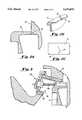
- the air separator 10which maintains an air seal separating compressed air for the burning cycle from cooling air for the turbine blades 22.
- the air separator 10meets with the combustion turbine discs 20 as shown generally at 25. Therefore, one face of the air separator 10 is "hidden" where it meets the first of the combustion turbine discs 20 which is referred to as the row 1 disc 15.
- FIG. 2Ais a enlarged view of the portion of the combustion turbine 25 where the air separator 10 meets with the first of the combustion turbine discs 20.
- FIG. 2Bis a three dimensional representation of the portion of the air separator 10 shown in FIG. 2A having a crack 32 forming on the surface of the air separator 10.
- FIG. 2Cis a top surface view of the same portion of the air separator 10 showing the crack 32 progressing from the contact interface 30 away from the row 1 disc 15.
- a nondestructive inspection devicefulfills this objective by providing an inspection sensor which is positioned near the surface of the rotating member by a holder assembly.
- the inspection sensormonitors the rotating member for a defective condition and outputs a signal related thereto.
- An angular position identification meansgenerates a signal indicating the angular position of the rotating member as it rotates.
- a recorderis also provided to record the signals related to the condition being monitored and the angular position of the rotating member. Based on the recorded signal, a skilled operator could identify a defective condition and its location in the rotating member.
- the inspection sensoris either an eddy current sensor or an ultrasound transducer, and the holder assembly is configured to interchangeably position either of these sensors.
- the recorderis either a strip chart recorder or a data processor having a memory and a display.
- the angular position identification meansprovides a magnetic belt having a plurality of magnets which is wrapped around the rotating member. An additional sensor, such as an eddy current sensor, detects the magnets as they rotate with the rotating member. The additional sensor provides a signal to the recorder indicating each magnet it detects as they rotate.
- the holder assemblycomprises an axial member such as a lead screw.
- a locking device and an attachment apparatusare connected to the axial member.
- the locking deviceclamps the holder assembly in place and the attachment apparatus connects either type of sensor to the axial member.
- the axial membercan be adjustably extended and its vertical position can be adjusted using an axial adjustment means and seating adjustment means, respectively, in a preferred embodiment of the invention. If an ultrasound transducer is used as the sensor, further adjustment means are provided for adjusting the angular skew of the ultrasound transducer and the size of the couplant gap to optimize the transmission of the ultrasound.
- a methodis also provided by the present invention in which a characteristic of a rotating member is sensed by a nondestructive inspection device. A signal indicative of the sensed characteristic is then generated and recorded. That signal is then compared to a known signal representation to identify the existence of a defective condition in the rotating member.
- the known signal representationis preferably generated by calibrating the inspection device using a reference standard having a known defect. A signal is generated from the calibration step and is then recorded. In a further preferred embodiment the angular position of the defect, if one exists, is also determined by monitoring the rotation of the rotating member.
- FIG. 1is a cross-sectional view of a combustion turbine engine
- FIG. 2Ais enlarged cross-sectional view of the air separator and combustion turbine disc interface
- FIG. 2Bis a three dimensional representation of the air separator having a crack formation
- FIG. 2Cis a top surface view of the air separator showing the progression of a crack in the air separator
- FIG. 3is a cross-sectional view of the inspection device according to the present invention positioned within an access port in a combustion turbine engine;
- FIG. 4is a detailed diagram of the inspection device according to a preferred embodiment of the present invention.
- FIG. 5is a block diagram of the inspection device according to a preferred implementation of the present invention.
- nondestructive inspection device of the present inventioncould be used for a number of different applications and for monitoring numerous conditions or characteristics of a rotating member, it will be described herein in connection with its use in monitoring crack formation in a combustion turbine air separator.
- FIG. 3A cross sectional view of a preferred embodiment of the inspection device within the combustion turbine for monitoring the air separator is shown in FIG. 3.
- An access port 40is formed in the torque tube housing 50.
- the inspection device shown generally at 100may be inserted through the opening of the access port 40 so that it extends towards the combustion turbine discs 20 over the surface of the air separator 10.
- FIG. 4is a detailed diagram of a nondestructive inspection device according to a preferred embodiment of the present invention.
- the inspection devicepreferably comprises two primary elements, the holder assembly 101 and a sensor 102a or 102b.
- the sensor 102a or 102bis preferably attached to the holder assembly 101 at one end.
- the sensormay be either an ultrasound transducer 102a or an eddy current sensor 102b. It should be understood that an ultrasound transducer would be used to detect the formation of a crack on the hidden surface of the air separator or the progression of a crack under the surface of the air separator, while the eddy current sensor would be used for monitoring the formation of a crack on the surface of the air separator.
- any appropriate sensor depending upon the desired applicationcould be used.
- an eddy current sensorit is more preferable to use the eddy current sensor described in U.S. Pat. No. 5,442,285.
- an appropriate support positioning devicewith the sensor to permit the sensor to be variably positioned over the surface to be monitored.
- the holder assembly 101comprises an axial member 104 as shown in FIG. 4.
- axial member 104is an axial lead screw.
- a means for attaching the sensor 102a or 102b to the axial member 104is shown as attachment apparatus 106.
- the attachment apparatus 106will provide angular skew adjustments, for example by rotating the sensor in the cylindrical opening in holder 102b. It should be understood that adjustments to the angular position of an ultrasound transducer, for example, would permit optimization of defect detection.
- the attachment apparatus 106should be capable of interchangeably attaching either an eddy current sensor or ultrasound transducer to the axial member 104.
- the attachment apparatus 106may include a specialized sensor holder such as eddy current probe holder 107b or an ultrasound transducer holder 107a as shown in FIG. 4.
- the attachment apparatus 106could be configured to attach two or more sensors to the axial member 104 simultaneously.
- An axial adjustment means 108is preferably provided as shown in FIG. 4 to position the attachment apparatus 106 so that it can extend further into the access port. It should be understood that if an ultrasound transducer is provided, axial adjustments may also be used to determine the location of a defect from a time-of-flight table based on the distance of the transducer from the rotating member, the angle of the ultrasound transmission, and the return time of the ultrasound transmission.
- the back end of the holder assembly 101preferably provides a locking clamp mechanism 110.
- the locking mechanism 110provides three locking clamps, two of which are shown at 111a and 111b.
- the locking mechanism 110holds the holder assembly 101 in place by clamping it to the sides of the access port 40 as shown in FIG. 3.
- fine and coarse vertical adjustments 112 and 114respectively, properly seat the sensor 102a or 102b for inspection.
- a pumping systemprovides couplant to the ultrasound transducer.
- Couplant hoses 115preferably run to each side of the holder assembly 101 and attach to injection ports 116 in the attachment apparatus 106.
- a gapis formed between the attachment apparatus 106 and the ultrasound transducer 102 which is defined as a couplant gap.
- the attachment apparatus 106preferably provides a couplant gap adjustment 118 for allowing the ultrasound transducer to ride on top of the couplant resulting in better transmission of the ultrasound.
- the couplant hoses 115 and sensor cabling 122exit the rear of the holder assembly 101 and are attached to a remote couplant pumping system and appropriate test instrumentation respectively. The appropriate test instrumentation would depend upon the particular sensor used in the nondestructive inspection device. For example, if an eddy current sensor is used, an eddy current test instrument would be provided. If an ultrasound transducer is used, a pulse echo ultrasonic device used for defect detection would be provided.
- the inspection device 102is inserted into the access hole 40 and clamped to the open diameter of the hole formed by access port 40.
- the sensoris positioned to the proper inspection location by adjusting the axial lead screw 104.
- FIG. 3shows the inspection device locked in place. Once the inspection device is locked in place, the inspection begins by initiating the rotor by placing the combustion turbine rotor on turning gear. As the ultrasound transducer or eddy current sensor detects a flaw, the appropriate test instrument generates a signal clearly discernible by a trained nondestructive engineering (NDE) operator that can be compared to reference signals generated from artificial discontinuities in a calibration test block.
- NDEnondestructive engineering
- FIG. 5A block diagram of a preferred implementation of the inspection device is shown in FIG. 5.
- the sensor 130is preferably calibrated against known defects in a section of the air separator known as a reference standard.
- a special calibration fixture and standard collectively shown as the calibration system 132are preferably provided for this calibration.
- the calibration system 132simulates the geometry of the actual field condition i.e., the formation of a crack in the air separator.
- the sensor 130 response from the artificial flawsis observed on a display of the test instrument 134 and the signal from the test instrument 134 is sent to a recorder 136 and used as the reference signal.
- the test instrument 134is a pulse echo ultrasonic device having an A-scan display.
- the test instrument 134is an eddy current defect detector having a polar and time base display. Both the pulse echo ultrasonic device and the eddy current defect detector are commercially available. Other variations and types of test equipment could likewise be used.
- Angular information preferably related to the air separator in a combustion turbineis obtained by placing a magnetic belt 138 around the combustion turbine shaft to monitor the magnetic belt's position as it rotates.
- Cermarium cobalt magnetsare spaced apart approximately every 10 degrees and another eddy current sensor 140 is positioned to sense or count the magnets 141 as the shaft turns.
- the eddy current responseis sent to a second channel of the recorder 136.
- the magnet position and ultrasound/eddy current flaw responsecan then be correlated to a known location on the air separator. It should be understood that encoders could be used on the shaft and decoders provided so that more accurate position information could be obtained.
- the recorder 136in one embodiment may be implemented using any suitable strip chart recorder. Alternatively, a data processor may be used to record and display the inspection data provided by the test instrumentation 134. However, it should be understood that numerous devices may be used to record the reference signal for subsequent use during actual inspection.
Landscapes
- Physics & Mathematics (AREA)
- Chemical & Material Sciences (AREA)
- Analytical Chemistry (AREA)
- Health & Medical Sciences (AREA)
- Life Sciences & Earth Sciences (AREA)
- Biochemistry (AREA)
- General Health & Medical Sciences (AREA)
- General Physics & Mathematics (AREA)
- Immunology (AREA)
- Pathology (AREA)
- Acoustics & Sound (AREA)
- Electrochemistry (AREA)
- Chemical Kinetics & Catalysis (AREA)
- Investigating Or Analyzing Materials By The Use Of Ultrasonic Waves (AREA)
- Investigating Or Analyzing Materials By The Use Of Magnetic Means (AREA)
Abstract
Description
Claims (16)
Priority Applications (1)
| Application Number | Priority Date | Filing Date | Title |
|---|---|---|---|
| US08/165,289US5670879A (en) | 1993-12-13 | 1993-12-13 | Nondestructive inspection device and method for monitoring defects inside a turbine engine |
Applications Claiming Priority (1)
| Application Number | Priority Date | Filing Date | Title |
|---|---|---|---|
| US08/165,289US5670879A (en) | 1993-12-13 | 1993-12-13 | Nondestructive inspection device and method for monitoring defects inside a turbine engine |
Publications (1)
| Publication Number | Publication Date |
|---|---|
| US5670879Atrue US5670879A (en) | 1997-09-23 |
Family
ID=22598285
Family Applications (1)
| Application Number | Title | Priority Date | Filing Date |
|---|---|---|---|
| US08/165,289Expired - LifetimeUS5670879A (en) | 1993-12-13 | 1993-12-13 | Nondestructive inspection device and method for monitoring defects inside a turbine engine |
Country Status (1)
| Country | Link |
|---|---|
| US (1) | US5670879A (en) |
Cited By (41)
| Publication number | Priority date | Publication date | Assignee | Title |
|---|---|---|---|---|
| US6487909B2 (en)* | 2001-02-05 | 2002-12-03 | Siemens Westinghouse Power Corporation | Acoustic waveguide sensing the condition of components within gas turbines |
| US6487922B1 (en) | 2000-09-25 | 2002-12-03 | Siemens Westinghouse Power Corporation | Steam turbine inlet sleeve inspection apparatus and method |
| US20030126928A1 (en)* | 2001-10-01 | 2003-07-10 | Siemens Westinghouse Power Corporation | Monitoring thermal barrier coating deterioration via acoustic response to gas flow, pressure and impact |
| US6619109B1 (en) | 2000-09-25 | 2003-09-16 | Siemens Westinghouse Power Corporation | Steam turbine inlet bell seal inspection apparatus and method |
| EP1302769A3 (en)* | 2001-10-15 | 2004-06-23 | Intermet Neunkirchen GmbH | Method for checking the quality of cast pieces |
| US6792809B1 (en) | 2003-05-02 | 2004-09-21 | Siemens Westinghouse Power Corporation | Self-aligning turbine disc inspection apparatus |
| US20050068050A1 (en)* | 2003-09-26 | 2005-03-31 | Duffy Timothy R. | Device for detecting a crack on a turbine blade of an aircraft engine |
| US20050199832A1 (en)* | 2004-03-10 | 2005-09-15 | Siemens Westinghouse Power Corporation | In situ combustion turbine engine airfoil inspection |
| EP1605259A1 (en)* | 2004-06-11 | 2005-12-14 | Snecma | Installation for non-destructive testing of a workpiece. |
| US20060017434A1 (en)* | 2004-07-23 | 2006-01-26 | Tenley Brenda C | Methods and apparatus for inspecting a component |
| US20060078193A1 (en)* | 2004-10-08 | 2006-04-13 | Siemens Westinghouse Power Corporation | Method of visually inspecting turbine blades and optical inspection system therefor |
| US20060109001A1 (en)* | 2004-11-19 | 2006-05-25 | Suh Ui W | Methods and apparatus for testing a component |
| US20060263216A1 (en)* | 2005-05-23 | 2006-11-23 | Siemens Westinghouse Power Corporation | Detection of gas turbine airfoil failure |
| US20070031242A1 (en)* | 2005-08-02 | 2007-02-08 | Francesco Colonna | Movement system for the inspection of a turbine |
| US20070108973A1 (en)* | 2005-09-28 | 2007-05-17 | Southwest Research Institute | Systems & methods for flaw detection and monitoring at elevated temperatures with wireless communication using surface embedded, monolithically integrated, thin-film, magnetically actuated sensors, and methods for fabricating the sensors |
| US20070129604A1 (en)* | 2005-12-07 | 2007-06-07 | Siemens Power Generation, Inc. | Remote viewing apparatus |
| US20070126422A1 (en)* | 2005-11-03 | 2007-06-07 | The Clock Spring Company L. P. | Conformable Eddy Current Array |
| US7305884B1 (en) | 2004-04-29 | 2007-12-11 | Henkel Corporation | In situ monitoring of reactive material using ultrasound |
| US20080008968A1 (en)* | 2006-07-06 | 2008-01-10 | Siemens Power Generation, Inc. | Coating method for non-destructive examination of articles of manufacture |
| WO2008031585A1 (en)* | 2006-09-15 | 2008-03-20 | Man Diesel Se | Determination of the remaining life of rotors and corresponding rotor |
| US20080079426A1 (en)* | 2006-09-29 | 2008-04-03 | Yutaka Suzuki | Eddy current testing apparatus and eddy current testing method |
| US20080245151A1 (en)* | 2007-04-03 | 2008-10-09 | General Electric Company | Method and apparatus for in-situ inspection of rotary machine components |
| US20100097057A1 (en)* | 2008-10-17 | 2010-04-22 | Thomas Karpen | Inspection apparatus for performing inspections |
| US20100199755A1 (en)* | 2007-06-20 | 2010-08-12 | Daniel Mainville | Aircraft engine pre-dressing unit for testing facility |
| US20100225902A1 (en)* | 2006-09-14 | 2010-09-09 | General Electric Company | Methods and apparatus for robotically inspecting gas turbine combustion components |
| US20100312494A1 (en)* | 2007-12-28 | 2010-12-09 | Sanghamithra Korukonda | Process and apparatus for testing a component using an omni-directional eddy current probe |
| US20110004452A1 (en)* | 2007-12-31 | 2011-01-06 | Sanghamithra Korukonda | Method for compensation of responses from eddy current probes |
| EP2415968A1 (en)* | 2010-08-04 | 2012-02-08 | Alstom Technology Ltd | Method for Checking the Mechanical Integrity of Stabilizing Elements on the Rotor Blades of a Turbine and Scanning Device for Implementing the Method |
| US8365584B1 (en)* | 2011-07-13 | 2013-02-05 | General Electric Company | Apparatus for inspecting turbomachine components in-situ |
| WO2013104900A1 (en)* | 2012-01-09 | 2013-07-18 | Isis Innovation Limited | Monitoring engine components |
| US20130215260A1 (en)* | 2010-05-03 | 2013-08-22 | United Technologies Corporation | Accurate machine tool inspection of turbine airfoil |
| EP2669670A1 (en)* | 2012-06-01 | 2013-12-04 | Siemens Aktiengesellschaft | Method for detecting a crack in rotor blades in the operation of a turboengine |
| US8640531B2 (en)* | 2012-04-17 | 2014-02-04 | General Electric Company | Turbine inspection system and related method of operation |
| WO2015050657A1 (en)* | 2013-10-02 | 2015-04-09 | Siemens Energy, Inc. | Turbine blade-mounted sensor fixture for tip gap measurement |
| US20150107341A1 (en)* | 2013-10-21 | 2015-04-23 | General Electric Company | Method and system for detecting surface features on turbine components |
| US9513117B2 (en) | 2013-10-02 | 2016-12-06 | Siemens Energy, Inc. | Situ blade mounted tip gap measurement for turbines |
| US9556737B2 (en) | 2013-11-18 | 2017-01-31 | Siemens Energy, Inc. | Air separator for gas turbine engine |
| US20170175584A1 (en)* | 2014-02-14 | 2017-06-22 | Harbin Institute Of Technology | Aero engine rotor air floatation assembling method and device based on gantry structure |
| US10222200B2 (en) | 2017-05-12 | 2019-03-05 | Siemens Energy, Inc. | Contactless, blade-tip clearance measurement for turbines |
| CN109580785A (en)* | 2017-09-29 | 2019-04-05 | 上海金艺检测技术有限公司 | Scanning tooling and method for turbine blade root defect |
| US20230314281A1 (en)* | 2022-04-04 | 2023-10-05 | Rolls-Royce Plc | Methods and systems of monitoring a condition of a component of a gas turbine engine |
Citations (14)
| Publication number | Priority date | Publication date | Assignee | Title |
|---|---|---|---|---|
| US4139822A (en)* | 1977-06-14 | 1979-02-13 | General Electric Company | Eddy current probe for inspecting interiors of gas turbines, said probe having pivotal adjustments and a borescope |
| US4380172A (en)* | 1981-02-19 | 1983-04-19 | General Electric Company | On-line rotor crack detection |
| US4507608A (en)* | 1981-03-12 | 1985-03-26 | Rheinmetall Gmbh. | Method and arrangement using a pair of resonant circuits for determining and indicating the position of an uneveness in the inner surface of pipes or other types of cylindrical structures |
| US4646010A (en)* | 1983-06-22 | 1987-02-24 | Jungner Marine Ab | Fluidically mounted apparatus for measuring the torque in a shaft |
| US4685335A (en)* | 1982-03-03 | 1987-08-11 | Hitachi, Ltd. | Method and apparatus for monitoring cracks of a rotatable body |
| US4741203A (en)* | 1986-11-21 | 1988-05-03 | Westinghouse Electric Corp. | Turbine inspection device and associated coil assembly and associated method |
| US4763274A (en)* | 1986-06-24 | 1988-08-09 | Westinghouse Electric Corp. | Machine implemented analysis eddy current data |
| US4866381A (en)* | 1986-04-08 | 1989-09-12 | Diesel Kiki Co., Ltd. | Plural magnet device for magnetically detecting rotation angle of a rotary body |
| US4902971A (en)* | 1988-09-14 | 1990-02-20 | Guzik Technical Enterprises, Inc. | Magnetic head and disc tester employing pivot arm on linearly movable slide |
| US4955269A (en)* | 1988-02-04 | 1990-09-11 | Westinghouse Electric Corp. | Turbine blade fatigue monitor |
| US5041785A (en)* | 1989-03-28 | 1991-08-20 | U.S. Philips Corporation | Device for measuring a relative displacement of two objects, including a magnetic scale and two mutually perpendicular magnetic sensors which produce two independent phase displaced signals |
| US5140264A (en)* | 1991-06-24 | 1992-08-18 | Westinghouse Electric Corp. | Method for non-destructively assessing the condition of a turbine blade using eddy current probes inserted within cooling holes |
| US5287735A (en)* | 1990-12-10 | 1994-02-22 | Sensortech L.P. | Engine misfire or roughness detection method and apparatus |
| US5329230A (en)* | 1991-07-15 | 1994-07-12 | General Electric Company | Carriage for eddy current probe having contact ball engagement between carriage and translation means |
- 1993
- 1993-12-13USUS08/165,289patent/US5670879A/ennot_activeExpired - Lifetime
Patent Citations (14)
| Publication number | Priority date | Publication date | Assignee | Title |
|---|---|---|---|---|
| US4139822A (en)* | 1977-06-14 | 1979-02-13 | General Electric Company | Eddy current probe for inspecting interiors of gas turbines, said probe having pivotal adjustments and a borescope |
| US4380172A (en)* | 1981-02-19 | 1983-04-19 | General Electric Company | On-line rotor crack detection |
| US4507608A (en)* | 1981-03-12 | 1985-03-26 | Rheinmetall Gmbh. | Method and arrangement using a pair of resonant circuits for determining and indicating the position of an uneveness in the inner surface of pipes or other types of cylindrical structures |
| US4685335A (en)* | 1982-03-03 | 1987-08-11 | Hitachi, Ltd. | Method and apparatus for monitoring cracks of a rotatable body |
| US4646010A (en)* | 1983-06-22 | 1987-02-24 | Jungner Marine Ab | Fluidically mounted apparatus for measuring the torque in a shaft |
| US4866381A (en)* | 1986-04-08 | 1989-09-12 | Diesel Kiki Co., Ltd. | Plural magnet device for magnetically detecting rotation angle of a rotary body |
| US4763274A (en)* | 1986-06-24 | 1988-08-09 | Westinghouse Electric Corp. | Machine implemented analysis eddy current data |
| US4741203A (en)* | 1986-11-21 | 1988-05-03 | Westinghouse Electric Corp. | Turbine inspection device and associated coil assembly and associated method |
| US4955269A (en)* | 1988-02-04 | 1990-09-11 | Westinghouse Electric Corp. | Turbine blade fatigue monitor |
| US4902971A (en)* | 1988-09-14 | 1990-02-20 | Guzik Technical Enterprises, Inc. | Magnetic head and disc tester employing pivot arm on linearly movable slide |
| US5041785A (en)* | 1989-03-28 | 1991-08-20 | U.S. Philips Corporation | Device for measuring a relative displacement of two objects, including a magnetic scale and two mutually perpendicular magnetic sensors which produce two independent phase displaced signals |
| US5287735A (en)* | 1990-12-10 | 1994-02-22 | Sensortech L.P. | Engine misfire or roughness detection method and apparatus |
| US5140264A (en)* | 1991-06-24 | 1992-08-18 | Westinghouse Electric Corp. | Method for non-destructively assessing the condition of a turbine blade using eddy current probes inserted within cooling holes |
| US5329230A (en)* | 1991-07-15 | 1994-07-12 | General Electric Company | Carriage for eddy current probe having contact ball engagement between carriage and translation means |
Cited By (76)
| Publication number | Priority date | Publication date | Assignee | Title |
|---|---|---|---|---|
| US6487922B1 (en) | 2000-09-25 | 2002-12-03 | Siemens Westinghouse Power Corporation | Steam turbine inlet sleeve inspection apparatus and method |
| US6619109B1 (en) | 2000-09-25 | 2003-09-16 | Siemens Westinghouse Power Corporation | Steam turbine inlet bell seal inspection apparatus and method |
| US6487909B2 (en)* | 2001-02-05 | 2002-12-03 | Siemens Westinghouse Power Corporation | Acoustic waveguide sensing the condition of components within gas turbines |
| US20030126928A1 (en)* | 2001-10-01 | 2003-07-10 | Siemens Westinghouse Power Corporation | Monitoring thermal barrier coating deterioration via acoustic response to gas flow, pressure and impact |
| US7062971B2 (en)* | 2001-10-01 | 2006-06-20 | Siemens Westinghouse Power Corporation | Monitoring thermal barrier coating deterioration via acoustic response to gas flow, pressure and impact |
| EP1302769A3 (en)* | 2001-10-15 | 2004-06-23 | Intermet Neunkirchen GmbH | Method for checking the quality of cast pieces |
| US6792809B1 (en) | 2003-05-02 | 2004-09-21 | Siemens Westinghouse Power Corporation | Self-aligning turbine disc inspection apparatus |
| US20050068050A1 (en)* | 2003-09-26 | 2005-03-31 | Duffy Timothy R. | Device for detecting a crack on a turbine blade of an aircraft engine |
| US6943570B2 (en) | 2003-09-26 | 2005-09-13 | Honeywell International, Inc. | Device for detecting a crack on a turbine blade of an aircraft engine |
| US20050199832A1 (en)* | 2004-03-10 | 2005-09-15 | Siemens Westinghouse Power Corporation | In situ combustion turbine engine airfoil inspection |
| US6992315B2 (en) | 2004-03-10 | 2006-01-31 | Siemens Westinghouse Power Corporation | In situ combustion turbine engine airfoil inspection |
| US7305884B1 (en) | 2004-04-29 | 2007-12-11 | Henkel Corporation | In situ monitoring of reactive material using ultrasound |
| EP1605259A1 (en)* | 2004-06-11 | 2005-12-14 | Snecma | Installation for non-destructive testing of a workpiece. |
| US20050274188A1 (en)* | 2004-06-11 | 2005-12-15 | Snecma Moteurs | Installation for non-destructive inspection of a part |
| FR2871567A1 (en)* | 2004-06-11 | 2005-12-16 | Snecma Moteurs Sa | NON-DESTRUCTIVE CONTROL INSTALLATION OF A WORKPIECE |
| US7305898B2 (en) | 2004-06-11 | 2007-12-11 | Snecma Moteurs | Installation for non-destructive inspection of a part |
| EP1621878A1 (en)* | 2004-07-23 | 2006-02-01 | General Electric Company | Apparatus for testing a component |
| US7190162B2 (en) | 2004-07-23 | 2007-03-13 | General Electric Company | Methods and apparatus for inspecting a component |
| US20060017434A1 (en)* | 2004-07-23 | 2006-01-26 | Tenley Brenda C | Methods and apparatus for inspecting a component |
| US20060078193A1 (en)* | 2004-10-08 | 2006-04-13 | Siemens Westinghouse Power Corporation | Method of visually inspecting turbine blades and optical inspection system therefor |
| US7489811B2 (en) | 2004-10-08 | 2009-02-10 | Siemens Energy, Inc. | Method of visually inspecting turbine blades and optical inspection system therefor |
| US20060109001A1 (en)* | 2004-11-19 | 2006-05-25 | Suh Ui W | Methods and apparatus for testing a component |
| US8013599B2 (en) | 2004-11-19 | 2011-09-06 | General Electric Company | Methods and apparatus for testing a component |
| US20060263216A1 (en)* | 2005-05-23 | 2006-11-23 | Siemens Westinghouse Power Corporation | Detection of gas turbine airfoil failure |
| US7412320B2 (en) | 2005-05-23 | 2008-08-12 | Siemens Power Generation, Inc. | Detection of gas turbine airfoil failure |
| US20070031242A1 (en)* | 2005-08-02 | 2007-02-08 | Francesco Colonna | Movement system for the inspection of a turbine |
| US7559739B2 (en) | 2005-08-02 | 2009-07-14 | Nuovo Pignone S.P.A. | Movement system for the inspection of a turbine |
| US20070108973A1 (en)* | 2005-09-28 | 2007-05-17 | Southwest Research Institute | Systems & methods for flaw detection and monitoring at elevated temperatures with wireless communication using surface embedded, monolithically integrated, thin-film, magnetically actuated sensors, and methods for fabricating the sensors |
| US8486545B2 (en) | 2005-09-28 | 2013-07-16 | Southwest Research Institute | Systems and methods for flaw detection and monitoring at elevated temperatures with wireless communication using surface embedded, monolithically integrated, thin-film, magnetically actuated sensors, and methods for fabricating the sensors |
| US7557570B2 (en) | 2005-11-03 | 2009-07-07 | The Clock Spring Company L.P. | System and method for producing color contour maps of surface defects of high pressure pipelines |
| US20070126422A1 (en)* | 2005-11-03 | 2007-06-07 | The Clock Spring Company L. P. | Conformable Eddy Current Array |
| US20070129604A1 (en)* | 2005-12-07 | 2007-06-07 | Siemens Power Generation, Inc. | Remote viewing apparatus |
| US8523764B2 (en) | 2005-12-07 | 2013-09-03 | Siemens Energy, Inc. | Remote viewing apparatus |
| US8986778B2 (en)* | 2006-07-06 | 2015-03-24 | Siemens Energy, Inc. | Coating method for non-destructive examination of articles of manufacture |
| US20080008968A1 (en)* | 2006-07-06 | 2008-01-10 | Siemens Power Generation, Inc. | Coating method for non-destructive examination of articles of manufacture |
| US20100225902A1 (en)* | 2006-09-14 | 2010-09-09 | General Electric Company | Methods and apparatus for robotically inspecting gas turbine combustion components |
| WO2008031585A1 (en)* | 2006-09-15 | 2008-03-20 | Man Diesel Se | Determination of the remaining life of rotors and corresponding rotor |
| US7872472B2 (en) | 2006-09-29 | 2011-01-18 | Hitachi, Ltd. | Eddy current testing apparatus and eddy current testing method |
| US7772840B2 (en) | 2006-09-29 | 2010-08-10 | Hitachi, Ltd. | Eddy current testing method |
| US20100085042A1 (en)* | 2006-09-29 | 2010-04-08 | Hitachi, Ltd. | Eddy current testing apparatus and eddy current testing method |
| EP1906181A3 (en)* | 2006-09-29 | 2008-05-21 | Hitachi, Ltd. | Eddy current testing appartus and method |
| US20080079426A1 (en)* | 2006-09-29 | 2008-04-03 | Yutaka Suzuki | Eddy current testing apparatus and eddy current testing method |
| US7654143B2 (en)* | 2007-04-03 | 2010-02-02 | General Electric Company | Method and apparatus for in-situ inspection of rotary machine components |
| US20080245151A1 (en)* | 2007-04-03 | 2008-10-09 | General Electric Company | Method and apparatus for in-situ inspection of rotary machine components |
| US20100199755A1 (en)* | 2007-06-20 | 2010-08-12 | Daniel Mainville | Aircraft engine pre-dressing unit for testing facility |
| US7861579B2 (en)* | 2007-06-20 | 2011-01-04 | Pratt & Whitney Canada Corp. | Aircraft engine pre-dressing unit for testing facility |
| US20100312494A1 (en)* | 2007-12-28 | 2010-12-09 | Sanghamithra Korukonda | Process and apparatus for testing a component using an omni-directional eddy current probe |
| US20110004452A1 (en)* | 2007-12-31 | 2011-01-06 | Sanghamithra Korukonda | Method for compensation of responses from eddy current probes |
| US20100097057A1 (en)* | 2008-10-17 | 2010-04-22 | Thomas Karpen | Inspection apparatus for performing inspections |
| US8217646B2 (en)* | 2008-10-17 | 2012-07-10 | Ge Inspection Technologies, Lp | Inspection apparatus for performing inspections |
| US20130215260A1 (en)* | 2010-05-03 | 2013-08-22 | United Technologies Corporation | Accurate machine tool inspection of turbine airfoil |
| US9976851B2 (en)* | 2010-05-03 | 2018-05-22 | United Technologies Corporation | Accurate machine tool inspection of turbine airfoil |
| US8844360B2 (en) | 2010-08-04 | 2014-09-30 | Alstom Technology Ltd | Method for checking the mechanical integrity of stabilizing elements on the rotor blades of a turbine and scanning device for implementing the method |
| DE102010033302A1 (en)* | 2010-08-04 | 2012-02-09 | Alstom Technology Ltd. | Method for checking the mechanical integrity of stabilizing elements on the blades of a turbine and scanning device for carrying out the method |
| EP2415968A1 (en)* | 2010-08-04 | 2012-02-08 | Alstom Technology Ltd | Method for Checking the Mechanical Integrity of Stabilizing Elements on the Rotor Blades of a Turbine and Scanning Device for Implementing the Method |
| US8365584B1 (en)* | 2011-07-13 | 2013-02-05 | General Electric Company | Apparatus for inspecting turbomachine components in-situ |
| CN104160269B (en)* | 2012-01-09 | 2017-12-12 | 牛津大学创新有限公司 | Monitor engine components |
| JP2015504166A (en)* | 2012-01-09 | 2015-02-05 | アイシス イノベーション リミテッド | Engine component monitoring |
| CN104160269A (en)* | 2012-01-09 | 2014-11-19 | Isis创新有限公司 | Monitoring engine components |
| US10191012B2 (en) | 2012-01-09 | 2019-01-29 | Oxford University Innovation Limited | Monitoring engine components |
| WO2013104900A1 (en)* | 2012-01-09 | 2013-07-18 | Isis Innovation Limited | Monitoring engine components |
| EP2653651A3 (en)* | 2012-04-17 | 2017-11-15 | General Electric Company | Turbine inspection system and related method of operation |
| US8640531B2 (en)* | 2012-04-17 | 2014-02-04 | General Electric Company | Turbine inspection system and related method of operation |
| EP2669670A1 (en)* | 2012-06-01 | 2013-12-04 | Siemens Aktiengesellschaft | Method for detecting a crack in rotor blades in the operation of a turboengine |
| WO2015050657A1 (en)* | 2013-10-02 | 2015-04-09 | Siemens Energy, Inc. | Turbine blade-mounted sensor fixture for tip gap measurement |
| US9068906B2 (en) | 2013-10-02 | 2015-06-30 | Siemens Energy, Inc. | Turbine blade-mounted sensor fixture for tip gap measurement |
| US9513117B2 (en) | 2013-10-02 | 2016-12-06 | Siemens Energy, Inc. | Situ blade mounted tip gap measurement for turbines |
| US9581440B2 (en) | 2013-10-02 | 2017-02-28 | Siemens Energy, Inc. | In-situ blade-mounted optical camera inspected systems for turbine engines |
| US20150107341A1 (en)* | 2013-10-21 | 2015-04-23 | General Electric Company | Method and system for detecting surface features on turbine components |
| US9348001B2 (en)* | 2013-10-21 | 2016-05-24 | General Electric Company | Method and system for detecting surface features on turbine components |
| US9556737B2 (en) | 2013-11-18 | 2017-01-31 | Siemens Energy, Inc. | Air separator for gas turbine engine |
| US20170175584A1 (en)* | 2014-02-14 | 2017-06-22 | Harbin Institute Of Technology | Aero engine rotor air floatation assembling method and device based on gantry structure |
| US9890661B2 (en)* | 2014-02-14 | 2018-02-13 | Harbin Institute Of Technology | Aero engine rotor air floatation assembling device based on gantry structure |
| US10222200B2 (en) | 2017-05-12 | 2019-03-05 | Siemens Energy, Inc. | Contactless, blade-tip clearance measurement for turbines |
| CN109580785A (en)* | 2017-09-29 | 2019-04-05 | 上海金艺检测技术有限公司 | Scanning tooling and method for turbine blade root defect |
| US20230314281A1 (en)* | 2022-04-04 | 2023-10-05 | Rolls-Royce Plc | Methods and systems of monitoring a condition of a component of a gas turbine engine |
Similar Documents
| Publication | Publication Date | Title |
|---|---|---|
| US5670879A (en) | Nondestructive inspection device and method for monitoring defects inside a turbine engine | |
| US4139822A (en) | Eddy current probe for inspecting interiors of gas turbines, said probe having pivotal adjustments and a borescope | |
| US4660419A (en) | Reference standard for calibration of ultrasonic arrays | |
| US7650790B2 (en) | Method of inspecting a component and an apparatus for inspecting a component | |
| US5442285A (en) | NDE eddy current sensor for very high scan rate applications in an operating combustion turbine | |
| JP5492188B2 (en) | Detachable quick disconnect system for non-destructive testing components | |
| CN102648408B (en) | Method and device for ultrasonic testing | |
| US4087749A (en) | Method and apparatus for normalizing the outputs of sequentially scanned magnetic flaw detectors | |
| US20130127452A1 (en) | Remote environment inspection apparatus and method | |
| US20090078742A1 (en) | Method and a device for Inspecting a pipe connection weld by an ultrasound probe | |
| US11733211B2 (en) | Method and device for testing a component non-destructively | |
| US4906927A (en) | Eddy current flaw detecting apparatus and method thereof | |
| US20230258600A1 (en) | Apparatus and method for inspecting an inner wall surface of a pipe | |
| US4194400A (en) | Ultrasonic inspection method | |
| FR2610110A1 (en) | STRUCTURAL DEFECT DETECTION DEVICE | |
| JP2009075101A (en) | Method and apparatus for detecting tooth defects in a generator rotor | |
| KR101787904B1 (en) | Wedge for detecting using ultrasonic and apparatus for detecting using ultrasonic including the wedge | |
| EP1155313A1 (en) | Method and device for measuring in situ the distance between two specific elements in a tubular pipe | |
| JPH036494A (en) | Pressurization measuring device and gauge for nuclear fuel rods, etc. | |
| US4167121A (en) | Precision ultrasonic evaluation and recording system | |
| WO2009094627A1 (en) | Method and apparatus for inspection of gas turbine discs | |
| US5986452A (en) | Apparatus and method for detecting flaws in conductive material | |
| KR200446596Y1 (en) | Leak test device of fuel pipe plug | |
| Heo et al. | A novel magnetic flux leakage sensor system for inspecting large diameter pipeline | |
| JPH05126803A (en) | Automatic ultrasonic flaw detector |
Legal Events
| Date | Code | Title | Description |
|---|---|---|---|
| AS | Assignment | Owner name:WESTINGHOUSE ELECTRIC CORPORATION, PENNSYLVANIA Free format text:ASSIGNMENT OF ASSIGNORS INTEREST;ASSIGNORS:ZOMBO, PAUL J.;GUENTHER, PAUL;MOORE, CHARLES C.;AND OTHERS;REEL/FRAME:006821/0926;SIGNING DATES FROM 19931115 TO 19931130 | |
| STCF | Information on status: patent grant | Free format text:PATENTED CASE | |
| AS | Assignment | Owner name:SIEMENS WESTINGHOUSE POWER CORPORATION, FLORIDA Free format text:ASSIGNMENT NUNC PRO TUNC EFFECTIVE AUGUST 19, 1998;ASSIGNOR:CBS CORPORATION, FORMERLY KNOWN AS WESTINGHOUSE ELECTRIC CORPORATION;REEL/FRAME:009605/0650 Effective date:19980929 | |
| FEPP | Fee payment procedure | Free format text:PAYOR NUMBER ASSIGNED (ORIGINAL EVENT CODE: ASPN); ENTITY STATUS OF PATENT OWNER: LARGE ENTITY | |
| FEPP | Fee payment procedure | Free format text:PAYER NUMBER DE-ASSIGNED (ORIGINAL EVENT CODE: RMPN); ENTITY STATUS OF PATENT OWNER: LARGE ENTITY Free format text:PAYOR NUMBER ASSIGNED (ORIGINAL EVENT CODE: ASPN); ENTITY STATUS OF PATENT OWNER: LARGE ENTITY | |
| FPAY | Fee payment | Year of fee payment:4 | |
| FEPP | Fee payment procedure | Free format text:PAYOR NUMBER ASSIGNED (ORIGINAL EVENT CODE: ASPN); ENTITY STATUS OF PATENT OWNER: LARGE ENTITY Free format text:PAYER NUMBER DE-ASSIGNED (ORIGINAL EVENT CODE: RMPN); ENTITY STATUS OF PATENT OWNER: LARGE ENTITY | |
| FPAY | Fee payment | Year of fee payment:8 | |
| AS | Assignment | Owner name:SIEMENS POWER GENERATION, INC., FLORIDA Free format text:CHANGE OF NAME;ASSIGNOR:SIEMENS WESTINGHOUSE POWER CORPORATION;REEL/FRAME:016996/0491 Effective date:20050801 | |
| FPAY | Fee payment | Year of fee payment:12 | |
| AS | Assignment | Owner name:SIEMENS ENERGY, INC., FLORIDA Free format text:CHANGE OF NAME;ASSIGNOR:SIEMENS POWER GENERATION, INC.;REEL/FRAME:022482/0740 Effective date:20081001 Owner name:SIEMENS ENERGY, INC.,FLORIDA Free format text:CHANGE OF NAME;ASSIGNOR:SIEMENS POWER GENERATION, INC.;REEL/FRAME:022482/0740 Effective date:20081001 |