US5669926A - Surgical instrument - Google Patents
Surgical instrumentDownload PDFInfo
- Publication number
- US5669926A US5669926AUS08/686,571US68657196AUS5669926AUS 5669926 AUS5669926 AUS 5669926AUS 68657196 AUS68657196 AUS 68657196AUS 5669926 AUS5669926 AUS 5669926A
- Authority
- US
- United States
- Prior art keywords
- bendable
- stem section
- surgical instrument
- section
- cutting tool
- Prior art date
- Legal status (The legal status is an assumption and is not a legal conclusion. Google has not performed a legal analysis and makes no representation as to the accuracy of the status listed.)
- Expired - Lifetime
Links
- 238000005452bendingMethods0.000claimsabstractdescription42
- 239000002184metalSubstances0.000claimsdescription4
- 230000000694effectsEffects0.000description3
- 239000012530fluidSubstances0.000description3
- 230000002262irrigationEffects0.000description2
- 238000003973irrigationMethods0.000description2
- 239000000463materialSubstances0.000description2
- 230000004048modificationEffects0.000description2
- 238000012986modificationMethods0.000description2
- XLYOFNOQVPJJNP-UHFFFAOYSA-NwaterSubstancesOXLYOFNOQVPJJNP-UHFFFAOYSA-N0.000description2
- 238000010276constructionMethods0.000description1
- 229920000260silasticPolymers0.000description1
Images


Classifications
- A—HUMAN NECESSITIES
- A61—MEDICAL OR VETERINARY SCIENCE; HYGIENE
- A61B—DIAGNOSIS; SURGERY; IDENTIFICATION
- A61B17/00—Surgical instruments, devices or methods
- A61B17/32—Surgical cutting instruments
- A61B17/320016—Endoscopic cutting instruments, e.g. arthroscopes, resectoscopes
- A61B17/32002—Endoscopic cutting instruments, e.g. arthroscopes, resectoscopes with continuously rotating, oscillating or reciprocating cutting instruments
- A—HUMAN NECESSITIES
- A61—MEDICAL OR VETERINARY SCIENCE; HYGIENE
- A61B—DIAGNOSIS; SURGERY; IDENTIFICATION
- A61B17/00—Surgical instruments, devices or methods
- A61B17/00234—Surgical instruments, devices or methods for minimally invasive surgery
- A61B2017/00292—Surgical instruments, devices or methods for minimally invasive surgery mounted on or guided by flexible, e.g. catheter-like, means
- A61B2017/003—Steerable
- A61B2017/00305—Constructional details of the flexible means
- A61B2017/00309—Cut-outs or slits
- A—HUMAN NECESSITIES
- A61—MEDICAL OR VETERINARY SCIENCE; HYGIENE
- A61B—DIAGNOSIS; SURGERY; IDENTIFICATION
- A61B17/00—Surgical instruments, devices or methods
- A61B17/28—Surgical forceps
- A61B17/29—Forceps for use in minimally invasive surgery
- A61B2017/2901—Details of shaft
- A61B2017/2905—Details of shaft flexible
- A—HUMAN NECESSITIES
- A61—MEDICAL OR VETERINARY SCIENCE; HYGIENE
- A61B—DIAGNOSIS; SURGERY; IDENTIFICATION
- A61B17/00—Surgical instruments, devices or methods
- A61B17/28—Surgical forceps
- A61B17/29—Forceps for use in minimally invasive surgery
- A61B2017/2926—Details of heads or jaws
- A61B2017/2927—Details of heads or jaws the angular position of the head being adjustable with respect to the shaft
- A61B2017/2929—Details of heads or jaws the angular position of the head being adjustable with respect to the shaft with a head rotatable about the longitudinal axis of the shaft
Definitions
- the present inventionrelates to a surgical instrument for removing tissue such as tissue from a human body.
- the present inventionrelates to a surgical instrument which has a rotatable cutting tool, is steerable, and provides suction for removing tissue which is cut.
- the instrumentmay be used, for example, in operations involving a spinal disc.
- the present inventionis a surgical instrument comprising a manually engageable handle.
- a first stem section having a longitudinal axisextends from the handle.
- a second stem sectionis connected between the first stem section and a cutting tool.
- the cutting toolincludes a rotatable cutter.
- the second stem sectionhas at least a portion which is bendable.
- a rotatable drive shaftis connected with the cutter and extends axially through the first stem section and the second stem section.
- the drive shafthas a flexible portion disposed in the flexible stem section.
- a passageextends axially through the drive shaft for conducting tissue from a location adjacent to the cutting tool through the second stem section toward the handle.
- a mechanismis connected to the bendable portion of the second stem section for bending the bendable portion to change the orientation of the cutting tool relative to the axis and to the first stem section from a first orientation to a second orientation.
- the bendable portion of the second stem sectionincludes means for enabling bending movement of the bendable portion by the mechanism to locate the cutting tool at the same angle relative to the longitudinal axis of the first stem section at more than one location along the length of the bendable portion.
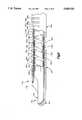
- FIG. 1is an illustration of a surgical instrument constructed in accordance with the present invention
- FIG. 2is an enlarged sectional view of a portion of the surgical instrument of FIG. 1;
- FIG. 3is a sectional view taken along line 3--3 of FIG. 2;
- FIG. 4is a sectional view taken along line 4--4 of FIG. 2;
- FIGS. 5-8are a series of views illustrating a portion of the surgical instrument of FIG. 1 shown in different positions;
- FIG. 9is a view similar to FIG. 2 of a portion of a surgical instrument constructed in accordance with a second embodiment of the present invention.
- FIGS. 1-8illustrate a surgical instrument 10 which is constructed in accordance with a first embodiment of the present invention.
- the surgical instrument 10includes a handle 12 and an actuator assembly 14.
- a stem section 16is connected with and projects from the handle 12.
- the stem section 16includes a first stem section 18 and a second stem section 20.
- a proximal end portion 22 of the first stem section 18is fixed to the handle 12.
- a proximal end portion 24 of the second stem section 20is connected with a distal end portion 26 of the first stem section 18.
- a rotary cutter assembly or shaver assembly 30is connected with a distal end portion 31 of the second stem section 20.
- the shaver assembly 30includes a fixed outer part 32 and a rotatable inner part 34.
- the first stem section 18is constructed so as to be substantially rigid, or non-bendable, during use of the surgical instrument 10.
- the rigid stem section 18has a longitudinal central axis 40 (FIG. 2) which forms a longitudinal central axis of the surgical instrument 10.
- the second stem section 20is constructed to be bendable during use of the surgical instrument 10.
- the actuator assembly 14is manually operable, in a manner described below, to bend the bendable stem section 20 to move the shaver assembly 30 between any one of many positions off the axis 40 relative to the rigid stem section 18.
- a suction pump(not shown) is preferably connected with the handle 12 at a connection indicated at 44 (FIG. 1).
- a source of water or other irrigation fluid(not shown) is preferably connected with the handle 12 at a connection indicated at 46 in FIG. 1.
- a control apparatus 48is connected with the surgical instrument 10 through a cord system 49.
- the stem section 16 (FIGS. 2-4) of the surgical instrument 10includes a main body portion 50.
- the main body portion 50is fixedly secured to the handle 12.
- the main body portion 50is made from a resilient plastic material, preferably Silastic (TRADEMARK) brand plastic available from Dow Corning Corporation.
- the main body portion 50 of the surgical instrument 10has a tubular, cylindrical configuration including parallel inner and outer surfaces 52 and 54.
- the main body portion 50extends along the length of both the rigid stem section 18 and the bendable stem section 20.
- a pair of cylindrical deflection control wire passages 60 and 62are formed in the main body portion 50.
- the passages 60 and 62extend parallel to each other and to the axis 40.
- the passages 60 and 62extend along the length of the rigid stem section 18 and along the length of the bendable stem section 20.
- the main body portion 50 of the instrument 10is selectively slotted or relieved, along at least a portion, and preferably all, of the length of the bendable stem section 20, to lower the bending resistance of the second stem section in a predetermined manner.
- a series of ten openings or slots 70, 72, 74, 76, 78, 80, 82, 84, 86 and 88are formed in the upper (as viewed in FIGS. 2 and 3) sector of the main body portion 50.
- Each one of the slots 70-88has a circumferential extent of about 180°.
- the slots 70-88define a series of ten relatively movable links 90, 92, 94, 96, 98, 100, 102, 104, 106 and 108.
- the links 90-108are the sections of the main body portion 50 which are located axially between adjacent slots 70-88.
- the slots 70-88act as pivot joints or pivot axes between the links 90-108.
- the links 90-108are pivotally interconnected by the material of the main body portion 50 which is not cut away at the slots 70-88.
- the links 90-108enable controlled movement of the shaver assembly 30 to a plurality of positions off the axis 40 as illustrated, for example, in FIGS. 5-8.
- the axially-measured distance between each pair of adjacent slots 70-88is predetermined and is uniform.
- the bending resistance of the main body portion 50, resulting from slot placementis uniform along the length of the bendable stem section 20 of the surgical instrument 10.
- the width (or axial extent) of each one of the slots 70-88is uniform along the length of the bendable stem section 20.
- the bending resistance of the main body portion 50, resulting from slot widthis uniform along the length of the bendable stem section 20 of the surgical instrument 10.
- the outer part 32 of the shaver assembly 30is fixedly secured in a known manner, such as by bonding, to a distal end portion 120 of the main body portion 50 of the instrument 10.
- the outer part 32 of the shaver assembly 30has a generally cylindrical, tubular configuration with a tissue opening 122 defined by a first cutting edge 124.
- the tissue opening 122communicates with a central chamber 126 in the outer part 32 of the shaver assembly 30.
- the shaver assembly 30is preferably made from metal and may be constructed in a manner similar to that disclosed in U.S. Pat. No. 4,598,710.
- a rotatable drive shaft 130is disposed radially inward of the main body portion 50 of the surgical instrument 10.
- a rigid portion 132 of the drive shaft 130is disposed within the rigid stem section 18.
- the rigid portion 132 of the drive shaft 130is a cylindrical metal tube which has parallel cylindrical inner and outer surfaces 134 and 136.
- the inner surface 134 of the rigid portion 132 of the drive shaft 130defines a central passage 138 of the rigid stem section 18.
- the rigid portion 132 of the drive shaft 130is connected with the drive shaft (not shown) of a suitable electric motor in the handle 12 and is rotatable about the longitudinal central axis 40 by operation of the motor.
- a flexible portion 142 of the drive shaft 130is disposed within the bendable portion of the main body portion 50 of the main body portion 50 of the surgical instrument 10.
- the flexible portion 142 of the drive shaft 130is preferably formed as a helical coil spring, preferably made from metal having a rectangular cross-sectional configuration, but could alternatively be formed in a different manner.
- the flexible portion 142 of the drive shaft 130is capable of transmitting rotational force from the rigid portion 132 of the drive shaft to the rotatable inner part 34 of the shaver assembly 30.
- the flexible portion 142 of the drive shaft 130has an axially extending, central passage 144.
- the flexible portion 142 of the drive shaft 132also provides a self-centering effect for the bendable stem section 20 of the surgical instrument 10. Specifically, when the bendable stem section 20 of the instrument 10 is bent to a condition off the axis 40, as described below, the resilience provided by the spring configuration of the flexible portion 124 of the drive shaft 130 returns the bendable stem section 20 to its linear position upon release of the bending force.
- the tubular plastic main body portion 50also has a self-centering effect.
- a plastic inner sheath 160 in the form of a shrink wrapoverlies the flexible portion 142 of the drive shaft 132.
- the sheath 160seals the openings between adjacent turns of the coil spring drive shaft 142.
- the sheath 160is, for clarity, shown with an exaggerated thickness in FIGS. 2 and 3.
- the rotatable inner part 34 of the shaver assembly 30is secured to a distal end 162 of the flexible portion 142 of the drive shaft 130.
- the inner part 34 of the shaver assembly 30has a generally cylindrical configuration and is rotatable within the central chamber 126 in the outer part 32 of the shaver assembly.
- the inner part 34 of the shaver assembly 30has a tissue opening 164 defined by a second cutting edge 166.
- the tissue opening 164 in the inner part 34 of the shaver assembly 30communicates with the central passage 144 in the flexible portion 142 of the drive shaft 130.
- a suction pump(not shown) is connected with the instrument handle 10 at the connection 44. Suction is applied to the shaver assembly 30 through the central passage 138 in the rigid stem section 18 and through the central passage 144 in the bendable stem section 20.
- the second cutting edge 166 on the inner part 34 of the shaver assembly 30cooperates with the first cutting edge 124 on the outer part 32 of the shaver assembly, in a known manner, to remove tissue.
- the removed tissueis drawn into the central chamber 126 of the shaver assembly 30 by suction applied through the central passage 138 of the rigid stem section 18 and through the central passage 144 of the flexible portion 142 of the drive shaft 130.
- the suctiondraws or pulls tissue from the area immediately adjacent to the shaver assembly 30 back through the center of the flexible portion 142 of the drive shaft 130 and through the center of the rigid portion 132 of the drive shaft, to the connection 44 and the suction conduit.
- water or other fluidcan be utilized to irrigate the area where tissue is removed by the shaver assembly 30.
- the irrigation fluidis conducted through the central passage 138 in the rigid stem section 18 and through the central passage 144 in the bendable stem section 20, to the shaver assembly 30.
- rotatable tissue cutting devicesmay be substituted for the shaver assembly 30.
- a generally spherical rotatable burr or routermay be used to abrade tissue.
- the particular type of shaver or shaver assembly which is connected with the bendable stem section 20will depend upon the surgical operation to be performed.
- the actuator assembly 14 of the surgical instrumentincludes a deflection control lever 170 (FIG. 1) which projects from the handle 12.
- the deflection control lever 170is supported for pivotal movement relative to the handle 12.
- the actuator assembly 14also includes two deflection control wires 172 and 174.
- the wires 172 and 174are preferably separate portions of a single loop of wire 176 which has its proximal ends connected for movement with the deflection control lever 170.
- the deflection control wires 172 and 174extend from the deflection control lever 170 through the deflection control wire passages 60 and 62, respectively, in the main body portion 50.
- the deflection control wires 172 and 174are connected in a force-transmitting relationship with the fixed portion 32 of the shaver assembly 30. Specifically, the wires 172 and 174 loop around a fixed portion 178 of the shaver assembly 30. As a result, tensile forces on the wires 172 and 174, resulting from movement of the actuator control lever 170, are transmitted to the shaver assembly 30.
- the surgical instrument 10is typically used in association with a cannula 200 (FIGS. 5-8) having an open distal end 202.
- the cannula 200is a known tubular member of any suitable construction which is used, in a known manner, to provide an open path through body tissue to the operating site.
- the surgical instrument 10is inserted axially through the cannula until at least the shaver assembly 30 protrudes from the distal end 202 of the cannula 200.
- a predetermined amount of the bendable stem section 20 of the surgical instrument 10may also protrude from the distal end 202 of the cannula 200, as described below.
- the second stem section 20 of the surgical instrumentis bendable at about the location of the distal end 202 of the cannula 200, to position the shaver assembly 30 in the desired location.
- the actuation control lever 170is pivoted relative to the handle 12 so as tension the deflection control wires 172 and 174.
- Tension in the wires 172 and 174is effective to pivot the bendable stem section 20 of the instrument in a clockwise direction as viewed in FIGS. 5-8.
- the shaver assembly 30is pulled in a clockwise direction (as viewed in FIGS. 5-8) from the linear position shown in FIG. 2 toward the position shown in FIG. 8.
- one or more of the links 90-108 of the bendable stem section 20pivot about one or more of the slots or pivot axes 70-88.
- the distal end portion 602 of the cannula 200acts as a fulcrum about which the surgical instrument 10 bends.
- the surgical instrument 10bends at different locations along its length, depending on how much of the surgical instrument protrudes from the distal end 202 of the cannula 200.
- the surgical instrument 10bends at different locations along the length of the bendable stem section 20 because of the restrictions on its movement resulting from the presence of the cannula 200.
- the bendable stem section 20 of a surgical instrument 10in accordance with the present invention, can be bent at the same angle relative to the longitudinal axis 40 at more than one location along the length of the bendable stem section 20. For example, as shown in FIG.
- the surgical instrument 10bends at the approximate location of the pivot axis 76.
- the shaver assembly 30 as shown in FIG. 6extends at an angle of 90° to the central axis 40, at the approximate location of the slot or pivot axis 72.
- the surgical instrument 10bends in a manner as shown in FIG. 7.
- the presence of the cannula 200causes the bendable stem section 20 of the surgical instrument 10 to bend at the approximate location of the most proximal pivot axis or slot 88.
- the shaver assembly 30 in FIG. 7extends at an angle of 90° to the central axis 40, at the approximate location of the pivot axis 88. This location is spaced apart from the bending location shown in FIG. 6 by a substantial distance along the length of the bendable stem section 20 of the surgical instrument 10.
- the positioning of the surgical instrument 10 relative to the cannula 200can control and determine the bending location.
- the wall of a body spacecan be used to control the bending.
- the tough outer wall of a spinal disccan act as the fulcrum for bending the surgical instrument 10 to perform work within the spinal disc.
- the bendable stem section 20 of the surgical instrument 10can bend up to 90° to 180°, or more, at almost any location along its length depending on the range of pivotal movement which is available at each pivot axis 70-88.
- the bendable stem section 20might be independently bendable by, for example, 18° at each of ten different locations along the length of the bendable stem section, thus providing a total of 180° of bending movement.
- the bendable stem section 20is shown in FIG. 8 bent through an arc 210 which has a circumferential extent of greater than 180°. The amount of bending of the bendable stem section 20 of the surgical instrument 10 is controlled by the amount of tension on the deflection control wires 172 and 174 and by the amount of movement of the deflection control lever 170.
- the shaver assembly 30can be positioned and used in substantially any position outside the distal end 202 of the cannula 200. This is enhanced by the fact that no portions of the surgical instrument 10 extend radially outward of the links 90-108 and so the surgical instrument can be "pistoned” or moved axially with little restriction even when the bendable stem section 20 is bent at 90° or more. These features provide a much larger operating field than is available with a surgical instrument which bends to 90° at only one location along its length.
- the actuator assembly 14can thus be operated to change the orientation of the shaver assembly 30 relative to the rigid portion 18 of the stem section 16 and relative to body tissue during an operation.
- the actuator assembly 14can be operated to positively change the orientation of the shaver assembly 30 through a range of 180° from the straight initial orientation.
- the drive shaft 130 and the inner shaver part 134are rotatable to effect tissue removal while the bendable stem section 20 is in any orientation.
- the bendable stem section 20can be deflected or bent under the influence of forces applied to the shaver assembly 30, relative to the straight initial orientation shown in FIG. 2.
- Devices constructed in accordance with the present inventionwhich exhibit uniform bending resistance along the length of the bendable stem section 20 bend in one manner only when bent in free space (for example, as viewed in FIG. 6).
- a cannula or a wall of a body spacefor example, is used to restrict and control the movement of the bendable stem section 20 of the device 10.
- devices constructed in accordance with the present inventionwhich are non-uniform along their length, that is, which have features to selectively vary the bending resistance along their length, can bend at different locations along their length even when bent in free space.
- a cannula or a wall of a body spacemay not be necessary to restrict and control the movement of the bendable stem section 20 of the device.
- Such devicesinclude the surgical instrument 10a, a portion of which is illustrated in FIG. 9.
- the surgical instrument 10ais identical to the surgical instrument 10 (FIGS. 1-8) with the exception of the placement and width of the slots in the main body portion.
- parts of the surgical instrument 10a(FIG. 9) which are the same as, or similar to, corresponding parts of the surgical instrument 10 (FIGS. 1-8) are given the same reference numeral with the suffix "a" attached.
- the distance between adjacent pairs of slots 70a-88a in the main body portion 50a along the length of the bendable stem section 20avaries, to vary the bending resistance of the main body portion and thus of the bendable stem section of the surgical instrument.
- the slots 78a-84aare spaced apart by a first distance along the length of the bendable stem section 20a of the surgical instrument 10a.
- the first distanceis relatively large. This tends to increase the bending resistance of the main body portion 50a, and thus of the bendable stem section 20a, at the location of the slots 78a-84a, because the slots are relatively far apart.
- the slots 84a-88aare spaced apart by a second distance along the length of the bendable stem section 20a of the surgical instrument 10a. The second distance is substantially less than the first distance. This tends to decrease the bending resistance of the main body portion 50a, at the location of the slots 84a-88a to a level which is less than the bending resistance at the location of the slots 78a-84a.
- the width (or axial extent) of at least some of the slots 70a-88a on the main body portion 50a of the surgical instrument 10avaries, from slot to slot, along the length of the bendable stem section 20a.
- the width of the slots 70a-76ais relatively great compared to the width of the slots 78a-88a. This tends to lower the bending resistance of the main body portion 50a, and thus of the bendable stem section 20a of the surgical instrument 10a, at the location of the slots 70a-76a.
Landscapes
- Health & Medical Sciences (AREA)
- Surgery (AREA)
- Life Sciences & Earth Sciences (AREA)
- Biomedical Technology (AREA)
- Nuclear Medicine, Radiotherapy & Molecular Imaging (AREA)
- Engineering & Computer Science (AREA)
- Orthopedic Medicine & Surgery (AREA)
- Heart & Thoracic Surgery (AREA)
- Medical Informatics (AREA)
- Molecular Biology (AREA)
- Animal Behavior & Ethology (AREA)
- General Health & Medical Sciences (AREA)
- Public Health (AREA)
- Veterinary Medicine (AREA)
- Surgical Instruments (AREA)
Abstract
Description
Claims (17)
Priority Applications (1)
| Application Number | Priority Date | Filing Date | Title |
|---|---|---|---|
| US08/686,571US5669926A (en) | 1993-01-25 | 1996-07-26 | Surgical instrument |
Applications Claiming Priority (2)
| Application Number | Priority Date | Filing Date | Title |
|---|---|---|---|
| US08/008,670US5540706A (en) | 1993-01-25 | 1993-01-25 | Surgical instrument |
| US08/686,571US5669926A (en) | 1993-01-25 | 1996-07-26 | Surgical instrument |
Related Parent Applications (1)
| Application Number | Title | Priority Date | Filing Date |
|---|---|---|---|
| US08/008,670Continuation-In-PartUS5540706A (en) | 1993-01-25 | 1993-01-25 | Surgical instrument |
Publications (1)
| Publication Number | Publication Date |
|---|---|
| US5669926Atrue US5669926A (en) | 1997-09-23 |
Family
ID=46251093
Family Applications (1)
| Application Number | Title | Priority Date | Filing Date |
|---|---|---|---|
| US08/686,571Expired - LifetimeUS5669926A (en) | 1993-01-25 | 1996-07-26 | Surgical instrument |
Country Status (1)
| Country | Link |
|---|---|
| US (1) | US5669926A (en) |
Cited By (129)
| Publication number | Priority date | Publication date | Assignee | Title |
|---|---|---|---|---|
| US5733298A (en)* | 1994-07-19 | 1998-03-31 | Linvatec Corporation | Endoscopic shaver blade window positioning system |
| WO1998056299A1 (en)* | 1997-06-11 | 1998-12-17 | Endius Incorporated | Surgical instrument |
| WO1999015090A1 (en)* | 1997-09-24 | 1999-04-01 | Smith & Nephew, Inc. | Steerable surgical instrument |
| US6030401A (en)* | 1998-10-07 | 2000-02-29 | Nuvasive, Inc. | Vertebral enplate decorticator and osteophyte resector |
| EP0986989A1 (en)* | 1998-09-17 | 2000-03-22 | Siegfried Hiltebrandt | Flexible shaft and surgical instrument comprising such a shaft |
| US6048339A (en)* | 1998-06-29 | 2000-04-11 | Endius Incorporated | Flexible surgical instruments with suction |
| DE19850520A1 (en)* | 1998-11-03 | 2000-05-18 | Storz Karl Gmbh & Co Kg | Medical instrument for removing tissue |
| US6419641B1 (en)* | 2000-11-28 | 2002-07-16 | Promex, Llc | Flexible tip medical instrument |
| US6423074B1 (en)* | 1999-12-21 | 2002-07-23 | Allergan Sales, Inc. | Flexible irrigation/aspiration tip assembly for providing irrigation to an eye capsule and for aspirating fluid from the eye capsule |
| US6464711B1 (en) | 1999-03-19 | 2002-10-15 | Medtronic Xomed, Inc. | Articulating mechanism for steerable surgical cutting instruments |
| WO2003022163A1 (en)* | 2001-09-12 | 2003-03-20 | Harmonia Medical Technologies, Inc. | Endoscopic cutting instrument |
| US6629986B1 (en)* | 1996-06-07 | 2003-10-07 | Scieran Technologies, Inc. | Apparatus and method for performing opthalmic procedures |
| US6645218B1 (en)* | 2002-08-05 | 2003-11-11 | Endius Incorporated | Surgical instrument |
| US6656195B2 (en) | 2000-09-22 | 2003-12-02 | Medtronic Xomed, Inc. | Flexible inner tubular members and rotary tissue cutting instruments having flexible inner tubular members |
| US20030236549A1 (en)* | 2000-07-21 | 2003-12-25 | Frank Bonadio | Surgical instrument |
| US20040102719A1 (en)* | 2002-11-22 | 2004-05-27 | Velocimed, L.L.C. | Guide wire control catheters for crossing occlusions and related methods of use |
| US20040193140A1 (en)* | 2003-03-27 | 2004-09-30 | Scimed Life Systems,Inc. | Medical device |
| US20050209530A1 (en)* | 2001-03-23 | 2005-09-22 | Stryker Puerto Rico Limited | Micro-invasive tissue removal device |
| WO2006092563A1 (en)* | 2005-03-04 | 2006-09-08 | Gyrus Ent, L.L.C. | Surgical instrument and method |
| US20060264904A1 (en)* | 2005-05-09 | 2006-11-23 | Kerby Walter L | Medical device |
| US20070055272A1 (en)* | 2005-08-16 | 2007-03-08 | Laurent Schaller | Spinal Tissue Distraction Devices |
| US20080004645A1 (en)* | 2006-06-30 | 2008-01-03 | Atheromed, Inc. | Atherectomy devices and methods |
| US20080021487A1 (en)* | 2006-07-19 | 2008-01-24 | Heisler Gary R | Endoscopic cutting instrument with axial and rotary motion |
| US20080064984A1 (en)* | 2001-03-23 | 2008-03-13 | Stryker Puerto Rico Limited | Micro-invasive device |
| EP1383414A4 (en)* | 2001-03-23 | 2008-04-02 | Stryker Puerto Rico Ltd | Micro-invasive nucleotomy device and method |
| US20080154272A1 (en)* | 2005-08-16 | 2008-06-26 | Laurent Schaller | Apparatus and Method for Treating Bone |
| US20080234687A1 (en)* | 2005-08-16 | 2008-09-25 | Laurent Schaller | Devices for treating the spine |
| US20090023988A1 (en)* | 2007-07-20 | 2009-01-22 | Richard Wolf Gmbh | Endoscopic Instrument |
| US7553275B2 (en) | 2004-08-31 | 2009-06-30 | Surgical Solutions Llc | Medical device with articulating shaft |
| US20090275966A1 (en)* | 2008-05-05 | 2009-11-05 | Miroslav Mitusina | Flexible inner members having flexible regions comprising a plurality of intertwined helical cuts |
| WO2010011956A1 (en) | 2008-07-25 | 2010-01-28 | Spine View, Inc. | Systems and methods for cable-based debriders |
| WO2010013059A1 (en) | 2008-07-31 | 2010-02-04 | Surgical Innovations Limited | Endoscopic surgical instrument |
| US7670284B2 (en) | 2004-08-31 | 2010-03-02 | Surgical Solutions Llc | Medical device with articulating shaft |
| WO2010115134A1 (en) | 2009-04-02 | 2010-10-07 | Spine View, Inc. | Minimally invasive discectomy |
| WO2010121172A1 (en) | 2009-04-17 | 2010-10-21 | Spine View, Inc. | Devices and methods for arched roof cutters |
| US7824345B2 (en) | 2003-12-22 | 2010-11-02 | Boston Scientific Scimed, Inc. | Medical device with push force limiter |
| US20100280526A1 (en)* | 2009-04-29 | 2010-11-04 | Arch Day Design, Llc | Medical Device With Articulating Shaft Mechanism |
| US7841994B2 (en) | 2007-11-02 | 2010-11-30 | Boston Scientific Scimed, Inc. | Medical device for crossing an occlusion in a vessel |
| US20100305470A1 (en)* | 2009-05-29 | 2010-12-02 | Promex Technologies, Llc | Flexible biopsy needle |
| US7850623B2 (en) | 2005-10-27 | 2010-12-14 | Boston Scientific Scimed, Inc. | Elongate medical device with continuous reinforcement member |
| US7878984B2 (en) | 2002-07-25 | 2011-02-01 | Boston Scientific Scimed, Inc. | Medical device for navigation through anatomy and method of making same |
| US7914466B2 (en) | 1995-12-07 | 2011-03-29 | Precision Vascular Systems, Inc. | Medical device with collapse-resistant liner and method of making same |
| US7914467B2 (en) | 2002-07-25 | 2011-03-29 | Boston Scientific Scimed, Inc. | Tubular member having tapered transition for use in a medical device |
| US20110184232A1 (en)* | 2008-07-31 | 2011-07-28 | Vhairi Maxwell | Endoscopic surgical instrument |
| US8007506B2 (en) | 2006-06-30 | 2011-08-30 | Atheromed, Inc. | Atherectomy devices and methods |
| US8022331B2 (en) | 2003-02-26 | 2011-09-20 | Boston Scientific Scimed, Inc. | Method of making elongated medical devices |
| US8070762B2 (en) | 2007-10-22 | 2011-12-06 | Atheromed Inc. | Atherectomy devices and methods |
| US8105246B2 (en) | 2007-08-03 | 2012-01-31 | Boston Scientific Scimed, Inc. | Elongate medical device having enhanced torque and methods thereof |
| JP2012502743A (en)* | 2008-09-18 | 2012-02-02 | ボストン サイエンティフィック サイムド,インコーポレイテッド | Medical device with preferential bending |
| US8137293B2 (en) | 2009-11-17 | 2012-03-20 | Boston Scientific Scimed, Inc. | Guidewires including a porous nickel-titanium alloy |
| WO2012068181A2 (en) | 2010-11-15 | 2012-05-24 | Spine View, Inc. | Tissue removal system with retention mechanism |
| WO2012088167A2 (en) | 2010-12-20 | 2012-06-28 | Spine View, Inc. | Articulating tissue removal systems and methods |
| US8236016B2 (en) | 2007-10-22 | 2012-08-07 | Atheromed, Inc. | Atherectomy devices and methods |
| US20120221035A1 (en)* | 2009-08-31 | 2012-08-30 | Harvey Stephen J | Surgical cutting accessory with flexible tube |
| US8361094B2 (en) | 2006-06-30 | 2013-01-29 | Atheromed, Inc. | Atherectomy devices and methods |
| US8377035B2 (en) | 2003-01-17 | 2013-02-19 | Boston Scientific Scimed, Inc. | Unbalanced reinforcement members for medical device |
| US8376961B2 (en) | 2008-04-07 | 2013-02-19 | Boston Scientific Scimed, Inc. | Micromachined composite guidewire structure with anisotropic bending properties |
| US8409114B2 (en) | 2007-08-02 | 2013-04-02 | Boston Scientific Scimed, Inc. | Composite elongate medical device including distal tubular member |
| US8449526B2 (en) | 2001-07-05 | 2013-05-28 | Boston Scientific Scimed, Inc. | Torqueable soft tip medical device and method of usage |
| US20130150831A1 (en)* | 2011-12-13 | 2013-06-13 | Symmetry Medical New Bedford, Inc | System and method for an articulating distal end of an endoscopic medical device |
| US8535243B2 (en) | 2008-09-10 | 2013-09-17 | Boston Scientific Scimed, Inc. | Medical devices and tapered tubular members for use in medical devices |
| US8535327B2 (en) | 2009-03-17 | 2013-09-17 | Benvenue Medical, Inc. | Delivery apparatus for use with implantable medical devices |
| US8551020B2 (en) | 2006-09-13 | 2013-10-08 | Boston Scientific Scimed, Inc. | Crossing guidewire |
| US8551021B2 (en) | 2010-03-31 | 2013-10-08 | Boston Scientific Scimed, Inc. | Guidewire with an improved flexural rigidity profile |
| US8556914B2 (en) | 2006-12-15 | 2013-10-15 | Boston Scientific Scimed, Inc. | Medical device including structure for crossing an occlusion in a vessel |
| US8591583B2 (en) | 2005-08-16 | 2013-11-26 | Benvenue Medical, Inc. | Devices for treating the spine |
| US8628549B2 (en) | 2006-06-30 | 2014-01-14 | Atheromed, Inc. | Atherectomy devices, systems, and methods |
| US8663227B2 (en) | 2011-12-03 | 2014-03-04 | Ouroboros Medical, Inc. | Single-unit cutting head systems for safe removal of nucleus pulposus tissue |
| US8795306B2 (en) | 2011-10-13 | 2014-08-05 | Atheromed, Inc. | Atherectomy apparatus, systems and methods |
| US8795202B2 (en) | 2011-02-04 | 2014-08-05 | Boston Scientific Scimed, Inc. | Guidewires and methods for making and using the same |
| US8795254B2 (en) | 2008-12-10 | 2014-08-05 | Boston Scientific Scimed, Inc. | Medical devices with a slotted tubular member having improved stress distribution |
| US8821477B2 (en) | 2007-08-06 | 2014-09-02 | Boston Scientific Scimed, Inc. | Alternative micromachined structures |
| WO2014158523A1 (en)* | 2013-03-14 | 2014-10-02 | C.R. Bard, Inc. | Articulating surgical instruments |
| US8951288B2 (en) | 2010-11-09 | 2015-02-10 | Benvenue Medical, Inc. | Devices and methods for treatment of a bone fracture |
| US20150080896A1 (en) | 2013-07-19 | 2015-03-19 | Ouroboros Medical, Inc. | Anti-clogging device for a vacuum-assisted, tissue removal system |
| EP2862526A1 (en)* | 2003-04-22 | 2015-04-22 | Covidien LP | Methods and devices for cutting tissue |
| US9072874B2 (en) | 2011-05-13 | 2015-07-07 | Boston Scientific Scimed, Inc. | Medical devices with a heat transfer region and a heat sink region and methods for manufacturing medical devices |
| KR101566766B1 (en) | 2014-04-17 | 2015-11-06 | (주)세신정밀 | Shaver handpiece |
| US9211134B2 (en) | 2012-04-09 | 2015-12-15 | Carefusion 2200, Inc. | Wrist assembly for articulating laparoscopic surgical instruments |
| US9308016B2 (en) | 2006-06-30 | 2016-04-12 | Atheromed, Inc. | Devices, systems, and methods for performing atherectomy including delivery of a bioactive material |
| US9314252B2 (en) | 2011-06-24 | 2016-04-19 | Benvenue Medical, Inc. | Devices and methods for treating bone tissue |
| US9314263B2 (en) | 2006-06-30 | 2016-04-19 | Atheromed, Inc. | Atherectomy devices, systems, and methods |
| US9445825B2 (en) | 2011-02-10 | 2016-09-20 | Wright Medical Technology, Inc. | Expandable surgical device |
| US9445784B2 (en) | 2005-09-22 | 2016-09-20 | Boston Scientific Scimed, Inc | Intravascular ultrasound catheter |
| US9474541B2 (en) | 2013-03-13 | 2016-10-25 | John R Zider | Surgical devices |
| US9492192B2 (en) | 2006-06-30 | 2016-11-15 | Atheromed, Inc. | Atherectomy devices, systems, and methods |
| US9675376B2 (en) | 2006-06-30 | 2017-06-13 | Atheromed, Inc. | Atherectomy devices and methods |
| US9788854B2 (en) | 1999-08-19 | 2017-10-17 | Covidien Lp | Debulking catheters and methods |
| US9788963B2 (en) | 2003-02-14 | 2017-10-17 | DePuy Synthes Products, Inc. | In-situ formed intervertebral fusion device and method |
| US9801647B2 (en) | 2006-05-26 | 2017-10-31 | Covidien Lp | Catheter including cutting element and energy emitting element |
| US9808595B2 (en) | 2007-08-07 | 2017-11-07 | Boston Scientific Scimed, Inc | Microfabricated catheter with improved bonding structure |
| US9901706B2 (en) | 2014-04-11 | 2018-02-27 | Boston Scientific Scimed, Inc. | Catheters and catheter shafts |
| US20180078354A1 (en)* | 2016-09-21 | 2018-03-22 | Ethicon, Inc. | Applicator instruments for dispensing surgical fasteners having articulating shafts |
| US9999438B2 (en) | 2003-04-22 | 2018-06-19 | Covidien Lp | Methods and devices for cutting tissue at a vascular location |
| WO2020115613A1 (en)* | 2018-12-04 | 2020-06-11 | Acclarent, Inc. | Bi-directional articulating surgical shaver |
| US10888433B2 (en) | 2016-12-14 | 2021-01-12 | DePuy Synthes Products, Inc. | Intervertebral implant inserter and related methods |
| US10940016B2 (en) | 2017-07-05 | 2021-03-09 | Medos International Sarl | Expandable intervertebral fusion cage |
| US10966840B2 (en) | 2010-06-24 | 2021-04-06 | DePuy Synthes Products, Inc. | Enhanced cage insertion assembly |
| US10973652B2 (en) | 2007-06-26 | 2021-04-13 | DePuy Synthes Products, Inc. | Highly lordosed fusion cage |
| US11129672B2 (en)* | 2019-04-04 | 2021-09-28 | Covidien Lp | Tissue resecting device including an articulatable cutting member |
| US11207096B2 (en) | 2006-06-30 | 2021-12-28 | Atheromed, Inc. | Devices systems and methods for cutting and removing occlusive material from a body lumen |
| US11273050B2 (en) | 2006-12-07 | 2022-03-15 | DePuy Synthes Products, Inc. | Intervertebral implant |
| US11304723B1 (en) | 2020-12-17 | 2022-04-19 | Avantec Vascular Corporation | Atherectomy devices that are self-driving with controlled deflection |
| US11344424B2 (en) | 2017-06-14 | 2022-05-31 | Medos International Sarl | Expandable intervertebral implant and related methods |
| US11351048B2 (en) | 2015-11-16 | 2022-06-07 | Boston Scientific Scimed, Inc. | Stent delivery systems with a reinforced deployment sheath |
| US11426290B2 (en) | 2015-03-06 | 2022-08-30 | DePuy Synthes Products, Inc. | Expandable intervertebral implant, system, kit and method |
| US11426286B2 (en) | 2020-03-06 | 2022-08-30 | Eit Emerging Implant Technologies Gmbh | Expandable intervertebral implant |
| US11446156B2 (en) | 2018-10-25 | 2022-09-20 | Medos International Sarl | Expandable intervertebral implant, inserter instrument, and related methods |
| US11446155B2 (en) | 2017-05-08 | 2022-09-20 | Medos International Sarl | Expandable cage |
| US11452607B2 (en) | 2010-10-11 | 2022-09-27 | DePuy Synthes Products, Inc. | Expandable interspinous process spacer implant |
| US11497619B2 (en) | 2013-03-07 | 2022-11-15 | DePuy Synthes Products, Inc. | Intervertebral implant |
| US11510788B2 (en) | 2016-06-28 | 2022-11-29 | Eit Emerging Implant Technologies Gmbh | Expandable, angularly adjustable intervertebral cages |
| JP2022550914A (en)* | 2019-10-07 | 2022-12-05 | ニコ コーポレイション | In-plane rotation cannula |
| US11596523B2 (en) | 2016-06-28 | 2023-03-07 | Eit Emerging Implant Technologies Gmbh | Expandable and angularly adjustable articulating intervertebral cages |
| US11602438B2 (en) | 2008-04-05 | 2023-03-14 | DePuy Synthes Products, Inc. | Expandable intervertebral implant |
| US11607321B2 (en) | 2009-12-10 | 2023-03-21 | DePuy Synthes Products, Inc. | Bellows-like expandable interbody fusion cage |
| US11612491B2 (en) | 2009-03-30 | 2023-03-28 | DePuy Synthes Products, Inc. | Zero profile spinal fusion cage |
| US11654033B2 (en) | 2010-06-29 | 2023-05-23 | DePuy Synthes Products, Inc. | Distractible intervertebral implant |
| US11737881B2 (en) | 2008-01-17 | 2023-08-29 | DePuy Synthes Products, Inc. | Expandable intervertebral implant and associated method of manufacturing the same |
| US11752009B2 (en) | 2021-04-06 | 2023-09-12 | Medos International Sarl | Expandable intervertebral fusion cage |
| US11793536B2 (en) | 2014-04-17 | 2023-10-24 | Stryker Corporation | Surgical tool having cables for selectively steering and locking a shaft in a bend |
| US11850160B2 (en) | 2021-03-26 | 2023-12-26 | Medos International Sarl | Expandable lordotic intervertebral fusion cage |
| US11911287B2 (en) | 2010-06-24 | 2024-02-27 | DePuy Synthes Products, Inc. | Lateral spondylolisthesis reduction cage |
| USRE49973E1 (en) | 2013-02-28 | 2024-05-21 | DePuy Synthes Products, Inc. | Expandable intervertebral implant, system, kit and method |
| US12090064B2 (en) | 2022-03-01 | 2024-09-17 | Medos International Sarl | Stabilization members for expandable intervertebral implants, and related systems and methods |
| US12220140B1 (en) | 2023-08-16 | 2025-02-11 | Avantec Vascular Corporation | Thrombectomy devices with lateral and vertical bias |
| US12290279B2 (en) | 2021-06-07 | 2025-05-06 | Avantec Vascular Corporation | Hybrid atherectomy devices |
| US12414785B1 (en) | 2025-03-17 | 2025-09-16 | Avantec Vascular Corporation | Cutters with pulsating vacuum control |
| US12440346B2 (en) | 2023-03-31 | 2025-10-14 | DePuy Synthes Products, Inc. | Expandable intervertebral implant |
Citations (13)
| Publication number | Priority date | Publication date | Assignee | Title |
|---|---|---|---|---|
| US4274414A (en)* | 1979-02-21 | 1981-06-23 | Dyonics, Inc. | Surgical instrument |
| US4362160A (en)* | 1979-07-24 | 1982-12-07 | Richard Wolf Gmbh | Endoscopes |
| US4499899A (en)* | 1983-01-21 | 1985-02-19 | Brimfield Precision, Inc. | Fiber-optic illuminated microsurgical scissors |
| US4517977A (en)* | 1981-07-24 | 1985-05-21 | Unisearch Limited | Co-axial tube surgical infusion/suction cutter tip |
| US4649919A (en)* | 1985-01-23 | 1987-03-17 | Precision Surgical Instruments, Inc. | Surgical instrument |
| US4763669A (en)* | 1986-01-09 | 1988-08-16 | Jaeger John C | Surgical instrument with adjustable angle of operation |
| US4834729A (en)* | 1986-12-30 | 1989-05-30 | Dyonics, Inc. | Arthroscopic surgical instrument |
| US4834069A (en)* | 1987-09-03 | 1989-05-30 | Kabushiki Kaisha Machida Seisakusho | Endoscope with improved inserting portion |
| US5025804A (en)* | 1989-07-12 | 1991-06-25 | Fuji Photo Optical Co., Ltd. | Endoscope angling mechanism |
| US5100426A (en)* | 1989-07-26 | 1992-03-31 | Fts Engineering, Inc. | Catheter for performing an atherectomy procedure |
| US5143475A (en)* | 1990-03-14 | 1992-09-01 | Kabushiki Kaisha Machida Seisakusho | Bending device |
| US5178129A (en)* | 1989-12-28 | 1993-01-12 | Kabushiki Kaisha Machida Seisakusho | Method of producing bending device |
| US5354311A (en)* | 1991-07-29 | 1994-10-11 | Smith & Nephew Dyonics Inc. | Deflecting forceps |
- 1996
- 1996-07-26USUS08/686,571patent/US5669926A/ennot_activeExpired - Lifetime
Patent Citations (13)
| Publication number | Priority date | Publication date | Assignee | Title |
|---|---|---|---|---|
| US4274414A (en)* | 1979-02-21 | 1981-06-23 | Dyonics, Inc. | Surgical instrument |
| US4362160A (en)* | 1979-07-24 | 1982-12-07 | Richard Wolf Gmbh | Endoscopes |
| US4517977A (en)* | 1981-07-24 | 1985-05-21 | Unisearch Limited | Co-axial tube surgical infusion/suction cutter tip |
| US4499899A (en)* | 1983-01-21 | 1985-02-19 | Brimfield Precision, Inc. | Fiber-optic illuminated microsurgical scissors |
| US4649919A (en)* | 1985-01-23 | 1987-03-17 | Precision Surgical Instruments, Inc. | Surgical instrument |
| US4763669A (en)* | 1986-01-09 | 1988-08-16 | Jaeger John C | Surgical instrument with adjustable angle of operation |
| US4834729A (en)* | 1986-12-30 | 1989-05-30 | Dyonics, Inc. | Arthroscopic surgical instrument |
| US4834069A (en)* | 1987-09-03 | 1989-05-30 | Kabushiki Kaisha Machida Seisakusho | Endoscope with improved inserting portion |
| US5025804A (en)* | 1989-07-12 | 1991-06-25 | Fuji Photo Optical Co., Ltd. | Endoscope angling mechanism |
| US5100426A (en)* | 1989-07-26 | 1992-03-31 | Fts Engineering, Inc. | Catheter for performing an atherectomy procedure |
| US5178129A (en)* | 1989-12-28 | 1993-01-12 | Kabushiki Kaisha Machida Seisakusho | Method of producing bending device |
| US5143475A (en)* | 1990-03-14 | 1992-09-01 | Kabushiki Kaisha Machida Seisakusho | Bending device |
| US5354311A (en)* | 1991-07-29 | 1994-10-11 | Smith & Nephew Dyonics Inc. | Deflecting forceps |
Cited By (291)
| Publication number | Priority date | Publication date | Assignee | Title |
|---|---|---|---|---|
| US5733298A (en)* | 1994-07-19 | 1998-03-31 | Linvatec Corporation | Endoscopic shaver blade window positioning system |
| US7914466B2 (en) | 1995-12-07 | 2011-03-29 | Precision Vascular Systems, Inc. | Medical device with collapse-resistant liner and method of making same |
| US6629986B1 (en)* | 1996-06-07 | 2003-10-07 | Scieran Technologies, Inc. | Apparatus and method for performing opthalmic procedures |
| WO1998056299A1 (en)* | 1997-06-11 | 1998-12-17 | Endius Incorporated | Surgical instrument |
| US5851212A (en)* | 1997-06-11 | 1998-12-22 | Endius Incorporated | Surgical instrument |
| WO1999015090A1 (en)* | 1997-09-24 | 1999-04-01 | Smith & Nephew, Inc. | Steerable surgical instrument |
| US5921956A (en)* | 1997-09-24 | 1999-07-13 | Smith & Nephew, Inc. | Surgical instrument |
| US6048339A (en)* | 1998-06-29 | 2000-04-11 | Endius Incorporated | Flexible surgical instruments with suction |
| EP0986989A1 (en)* | 1998-09-17 | 2000-03-22 | Siegfried Hiltebrandt | Flexible shaft and surgical instrument comprising such a shaft |
| US6030401A (en)* | 1998-10-07 | 2000-02-29 | Nuvasive, Inc. | Vertebral enplate decorticator and osteophyte resector |
| US6251120B1 (en) | 1998-11-03 | 2001-06-26 | Karl Storz Gmbh & Co., Kg | Medical instrument for removing tissue |
| DE19850520A1 (en)* | 1998-11-03 | 2000-05-18 | Storz Karl Gmbh & Co Kg | Medical instrument for removing tissue |
| DE19850520B4 (en)* | 1998-11-03 | 2004-10-14 | Karl Storz Gmbh & Co. Kg | Medical instrument for removing tissue |
| US6464711B1 (en) | 1999-03-19 | 2002-10-15 | Medtronic Xomed, Inc. | Articulating mechanism for steerable surgical cutting instruments |
| US9486237B2 (en) | 1999-08-19 | 2016-11-08 | Covidien Lp | Methods and devices for cutting tissue |
| US9532799B2 (en) | 1999-08-19 | 2017-01-03 | Covidien Lp | Method and devices for cutting tissue |
| US9788854B2 (en) | 1999-08-19 | 2017-10-17 | Covidien Lp | Debulking catheters and methods |
| US10022145B2 (en) | 1999-08-19 | 2018-07-17 | Covidien Lp | Methods and devices for cutting tissue |
| US6423074B1 (en)* | 1999-12-21 | 2002-07-23 | Allergan Sales, Inc. | Flexible irrigation/aspiration tip assembly for providing irrigation to an eye capsule and for aspirating fluid from the eye capsule |
| US8157817B2 (en) | 2000-07-21 | 2012-04-17 | Atropos Limited | Surgical instrument |
| US20030236549A1 (en)* | 2000-07-21 | 2003-12-25 | Frank Bonadio | Surgical instrument |
| US6656195B2 (en) | 2000-09-22 | 2003-12-02 | Medtronic Xomed, Inc. | Flexible inner tubular members and rotary tissue cutting instruments having flexible inner tubular members |
| US20050113714A1 (en)* | 2000-11-28 | 2005-05-26 | Promex Technologies, Llc | Flexible tip medical instrument |
| US20030208136A1 (en)* | 2000-11-28 | 2003-11-06 | Promex, Inc. | Flexible tip medical instrument |
| US7048694B2 (en)* | 2000-11-28 | 2006-05-23 | Promex Technologies, Llc | Flexible tip medical instrument |
| US20060184153A1 (en)* | 2000-11-28 | 2006-08-17 | Promex Technologies, Llc | Flexible tip medical instrument |
| US6419641B1 (en)* | 2000-11-28 | 2002-07-16 | Promex, Llc | Flexible tip medical instrument |
| US7841990B2 (en) | 2000-11-28 | 2010-11-30 | Promex Technologies, Llc | Flexible tip medical instrument |
| WO2002060312A3 (en)* | 2000-11-28 | 2003-04-17 | Promex Inc | Flexible tip medical instrument |
| US20080064984A1 (en)* | 2001-03-23 | 2008-03-13 | Stryker Puerto Rico Limited | Micro-invasive device |
| US20050209530A1 (en)* | 2001-03-23 | 2005-09-22 | Stryker Puerto Rico Limited | Micro-invasive tissue removal device |
| US7591790B2 (en) | 2001-03-23 | 2009-09-22 | Stryker Puerto Rico Limited | Micro-invasive device |
| EP1383414A4 (en)* | 2001-03-23 | 2008-04-02 | Stryker Puerto Rico Ltd | Micro-invasive nucleotomy device and method |
| US8449526B2 (en) | 2001-07-05 | 2013-05-28 | Boston Scientific Scimed, Inc. | Torqueable soft tip medical device and method of usage |
| WO2003022163A1 (en)* | 2001-09-12 | 2003-03-20 | Harmonia Medical Technologies, Inc. | Endoscopic cutting instrument |
| US8048004B2 (en) | 2002-07-25 | 2011-11-01 | Precision Vascular Systems, Inc. | Medical device for navigation through anatomy and method of making same |
| US7914467B2 (en) | 2002-07-25 | 2011-03-29 | Boston Scientific Scimed, Inc. | Tubular member having tapered transition for use in a medical device |
| US8939916B2 (en) | 2002-07-25 | 2015-01-27 | Precision Vascular Systems, Inc. | Medical device for navigation through anatomy and method of making same |
| US8257279B2 (en) | 2002-07-25 | 2012-09-04 | Boston Scientific Scimed, Inc. | Medical device for navigation through anatomy and method of making same |
| US7878984B2 (en) | 2002-07-25 | 2011-02-01 | Boston Scientific Scimed, Inc. | Medical device for navigation through anatomy and method of making same |
| US8936558B2 (en) | 2002-07-25 | 2015-01-20 | Precision Vascular Systems, Inc. | Medical device for navigation through anatomy and method of making same |
| US8932235B2 (en) | 2002-07-25 | 2015-01-13 | Precision Vascular Systems, Inc. | Medical device for navigation through anatomy and method of making same |
| US8900163B2 (en) | 2002-07-25 | 2014-12-02 | Precision Vascular Systems, Inc. | Medical device for navigation through anatomy and method of making same |
| US8870790B2 (en) | 2002-07-25 | 2014-10-28 | Boston Scientific Scimed, Inc. | Medical device for navigation through anatomy and method of making same |
| US8915865B2 (en) | 2002-07-25 | 2014-12-23 | Precision Vascular Systems, Inc. | Medical device for navigation through anatomy and method of making same |
| US6645218B1 (en)* | 2002-08-05 | 2003-11-11 | Endius Incorporated | Surgical instrument |
| US20040102719A1 (en)* | 2002-11-22 | 2004-05-27 | Velocimed, L.L.C. | Guide wire control catheters for crossing occlusions and related methods of use |
| US20090005755A1 (en)* | 2002-11-22 | 2009-01-01 | Keith Peter T | Guide wire control catheter for crossing occlusions and related methods of use |
| US8377035B2 (en) | 2003-01-17 | 2013-02-19 | Boston Scientific Scimed, Inc. | Unbalanced reinforcement members for medical device |
| US10583013B2 (en) | 2003-02-14 | 2020-03-10 | DePuy Synthes Products, Inc. | In-situ formed intervertebral fusion device and method |
| US10555817B2 (en) | 2003-02-14 | 2020-02-11 | DePuy Synthes Products, Inc. | In-situ formed intervertebral fusion device and method |
| US10085843B2 (en) | 2003-02-14 | 2018-10-02 | DePuy Synthes Products, Inc. | In-situ formed intervertebral fusion device and method |
| US11432938B2 (en) | 2003-02-14 | 2022-09-06 | DePuy Synthes Products, Inc. | In-situ intervertebral fusion device and method |
| US11207187B2 (en) | 2003-02-14 | 2021-12-28 | DePuy Synthes Products, Inc. | In-situ formed intervertebral fusion device and method |
| US11096794B2 (en) | 2003-02-14 | 2021-08-24 | DePuy Synthes Products, Inc. | In-situ formed intervertebral fusion device and method |
| US10786361B2 (en) | 2003-02-14 | 2020-09-29 | DePuy Synthes Products, Inc. | In-situ formed intervertebral fusion device and method |
| US10639164B2 (en) | 2003-02-14 | 2020-05-05 | DePuy Synthes Products, Inc. | In-situ formed intervertebral fusion device and method |
| US9925060B2 (en) | 2003-02-14 | 2018-03-27 | DePuy Synthes Products, Inc. | In-situ formed intervertebral fusion device and method |
| US9814589B2 (en) | 2003-02-14 | 2017-11-14 | DePuy Synthes Products, Inc. | In-situ formed intervertebral fusion device and method |
| US10575959B2 (en) | 2003-02-14 | 2020-03-03 | DePuy Synthes Products, Inc. | In-situ formed intervertebral fusion device and method |
| US9814590B2 (en) | 2003-02-14 | 2017-11-14 | DePuy Synthes Products, Inc. | In-situ formed intervertebral fusion device and method |
| US9808351B2 (en) | 2003-02-14 | 2017-11-07 | DePuy Synthes Products, Inc. | In-situ formed intervertebral fusion device and method |
| US10376372B2 (en) | 2003-02-14 | 2019-08-13 | DePuy Synthes Products, Inc. | In-situ formed intervertebral fusion device and method |
| US9801729B2 (en) | 2003-02-14 | 2017-10-31 | DePuy Synthes Products, Inc. | In-situ formed intervertebral fusion device and method |
| US9788963B2 (en) | 2003-02-14 | 2017-10-17 | DePuy Synthes Products, Inc. | In-situ formed intervertebral fusion device and method |
| US10405986B2 (en) | 2003-02-14 | 2019-09-10 | DePuy Synthes Products, Inc. | In-situ formed intervertebral fusion device and method |
| US10420651B2 (en) | 2003-02-14 | 2019-09-24 | DePuy Synthes Products, Inc. | In-situ formed intervertebral fusion device and method |
| US10433971B2 (en) | 2003-02-14 | 2019-10-08 | DePuy Synthes Products, Inc. | In-situ formed intervertebral fusion device and method |
| US10492918B2 (en) | 2003-02-14 | 2019-12-03 | DePuy Synthes Products, Inc. | In-situ formed intervertebral fusion device and method |
| US8022331B2 (en) | 2003-02-26 | 2011-09-20 | Boston Scientific Scimed, Inc. | Method of making elongated medical devices |
| US9592363B2 (en) | 2003-03-27 | 2017-03-14 | Boston Scientific Scimed, Inc. | Medical device |
| US10207077B2 (en) | 2003-03-27 | 2019-02-19 | Boston Scientific Scimed, Inc. | Medical device |
| US7001369B2 (en)* | 2003-03-27 | 2006-02-21 | Scimed Life Systems, Inc. | Medical device |
| US8182465B2 (en) | 2003-03-27 | 2012-05-22 | Boston Scientific Scimed, Inc. | Medical device |
| US7540865B2 (en) | 2003-03-27 | 2009-06-02 | Boston Scientific Scimed, Inc. | Medical device |
| US9023011B2 (en) | 2003-03-27 | 2015-05-05 | Boston Scientific Scimed, Inc. | Medical device |
| US8636716B2 (en) | 2003-03-27 | 2014-01-28 | Boston Scientific Scimed, Inc. | Medical device |
| US20040193140A1 (en)* | 2003-03-27 | 2004-09-30 | Scimed Life Systems,Inc. | Medical device |
| US8048060B2 (en) | 2003-03-27 | 2011-11-01 | Boston Scientific Scimed, Inc. | Medical device |
| US9999438B2 (en) | 2003-04-22 | 2018-06-19 | Covidien Lp | Methods and devices for cutting tissue at a vascular location |
| EP2862526A1 (en)* | 2003-04-22 | 2015-04-22 | Covidien LP | Methods and devices for cutting tissue |
| US7824345B2 (en) | 2003-12-22 | 2010-11-02 | Boston Scientific Scimed, Inc. | Medical device with push force limiter |
| US20100160736A1 (en)* | 2004-08-31 | 2010-06-24 | Surgical Solutions Llc | Medical Device With Articulating Shaft |
| US7670284B2 (en) | 2004-08-31 | 2010-03-02 | Surgical Solutions Llc | Medical device with articulating shaft |
| US9339286B2 (en) | 2004-08-31 | 2016-05-17 | Surgical Solutions Llc | Medical device with articulating shaft |
| US7553275B2 (en) | 2004-08-31 | 2009-06-30 | Surgical Solutions Llc | Medical device with articulating shaft |
| US7699846B2 (en) | 2005-03-04 | 2010-04-20 | Gyrus Ent L.L.C. | Surgical instrument and method |
| US20060264927A1 (en)* | 2005-03-04 | 2006-11-23 | Gyrus Ent, L.L.C. | Surgical instrument and method |
| WO2006092563A1 (en)* | 2005-03-04 | 2006-09-08 | Gyrus Ent, L.L.C. | Surgical instrument and method |
| US20060264904A1 (en)* | 2005-05-09 | 2006-11-23 | Kerby Walter L | Medical device |
| US9066808B2 (en) | 2005-08-16 | 2015-06-30 | Benvenue Medical, Inc. | Method of interdigitating flowable material with bone tissue |
| US8882836B2 (en) | 2005-08-16 | 2014-11-11 | Benvenue Medical, Inc. | Apparatus and method for treating bone |
| US10028840B2 (en) | 2005-08-16 | 2018-07-24 | Izi Medical Products, Llc | Spinal tissue distraction devices |
| US7785368B2 (en) | 2005-08-16 | 2010-08-31 | Benvenue Medical, Inc. | Spinal tissue distraction devices |
| US8979929B2 (en) | 2005-08-16 | 2015-03-17 | Benvenue Medical, Inc. | Spinal tissue distraction devices |
| US7670375B2 (en) | 2005-08-16 | 2010-03-02 | Benvenue Medical, Inc. | Methods for limiting the movement of material introduced between layers of spinal tissue |
| US9044338B2 (en) | 2005-08-16 | 2015-06-02 | Benvenue Medical, Inc. | Spinal tissue distraction devices |
| US8961609B2 (en) | 2005-08-16 | 2015-02-24 | Benvenue Medical, Inc. | Devices for distracting tissue layers of the human spine |
| US8366773B2 (en) | 2005-08-16 | 2013-02-05 | Benvenue Medical, Inc. | Apparatus and method for treating bone |
| US9788974B2 (en) | 2005-08-16 | 2017-10-17 | Benvenue Medical, Inc. | Spinal tissue distraction devices |
| US20080154272A1 (en)* | 2005-08-16 | 2008-06-26 | Laurent Schaller | Apparatus and Method for Treating Bone |
| US8057544B2 (en) | 2005-08-16 | 2011-11-15 | Benvenue Medical, Inc. | Methods of distracting tissue layers of the human spine |
| US20080234687A1 (en)* | 2005-08-16 | 2008-09-25 | Laurent Schaller | Devices for treating the spine |
| US8454617B2 (en) | 2005-08-16 | 2013-06-04 | Benvenue Medical, Inc. | Devices for treating the spine |
| US7955391B2 (en) | 2005-08-16 | 2011-06-07 | Benvenue Medical, Inc. | Methods for limiting the movement of material introduced between layers of spinal tissue |
| US7670374B2 (en) | 2005-08-16 | 2010-03-02 | Benvenue Medical, Inc. | Methods of distracting tissue layers of the human spine |
| US7963993B2 (en) | 2005-08-16 | 2011-06-21 | Benvenue Medical, Inc. | Methods of distracting tissue layers of the human spine |
| US20070123986A1 (en)* | 2005-08-16 | 2007-05-31 | Laurent Schaller | Methods of Distracting Tissue Layers of the Human Spine |
| US9259326B2 (en) | 2005-08-16 | 2016-02-16 | Benvenue Medical, Inc. | Spinal tissue distraction devices |
| US8808376B2 (en) | 2005-08-16 | 2014-08-19 | Benvenue Medical, Inc. | Intravertebral implants |
| US8556978B2 (en) | 2005-08-16 | 2013-10-15 | Benvenue Medical, Inc. | Devices and methods for treating the vertebral body |
| US7967865B2 (en) | 2005-08-16 | 2011-06-28 | Benvenue Medical, Inc. | Devices for limiting the movement of material introduced between layers of spinal tissue |
| US8591583B2 (en) | 2005-08-16 | 2013-11-26 | Benvenue Medical, Inc. | Devices for treating the spine |
| US8801787B2 (en) | 2005-08-16 | 2014-08-12 | Benvenue Medical, Inc. | Methods of distracting tissue layers of the human spine |
| US20070055272A1 (en)* | 2005-08-16 | 2007-03-08 | Laurent Schaller | Spinal Tissue Distraction Devices |
| US9326866B2 (en) | 2005-08-16 | 2016-05-03 | Benvenue Medical, Inc. | Devices for treating the spine |
| US7666226B2 (en) | 2005-08-16 | 2010-02-23 | Benvenue Medical, Inc. | Spinal tissue distraction devices |
| US7666227B2 (en) | 2005-08-16 | 2010-02-23 | Benvenue Medical, Inc. | Devices for limiting the movement of material introduced between layers of spinal tissue |
| US7967864B2 (en) | 2005-08-16 | 2011-06-28 | Benvenue Medical, Inc. | Spinal tissue distraction devices |
| US9445784B2 (en) | 2005-09-22 | 2016-09-20 | Boston Scientific Scimed, Inc | Intravascular ultrasound catheter |
| US7850623B2 (en) | 2005-10-27 | 2010-12-14 | Boston Scientific Scimed, Inc. | Elongate medical device with continuous reinforcement member |
| US8231551B2 (en) | 2005-10-27 | 2012-07-31 | Boston Scientific Scimed, Inc. | Elongate medical device with continuous reinforcement member |
| US11666355B2 (en) | 2006-05-26 | 2023-06-06 | Covidien Lp | Catheter including cutting element and energy emitting element |
| US9801647B2 (en) | 2006-05-26 | 2017-10-31 | Covidien Lp | Catheter including cutting element and energy emitting element |
| US10588653B2 (en) | 2006-05-26 | 2020-03-17 | Covidien Lp | Catheter including cutting element and energy emitting element |
| US8888801B2 (en) | 2006-06-30 | 2014-11-18 | Atheromed, Inc. | Atherectomy devices and methods |
| US9675376B2 (en) | 2006-06-30 | 2017-06-13 | Atheromed, Inc. | Atherectomy devices and methods |
| US11207096B2 (en) | 2006-06-30 | 2021-12-28 | Atheromed, Inc. | Devices systems and methods for cutting and removing occlusive material from a body lumen |
| US9308016B2 (en) | 2006-06-30 | 2016-04-12 | Atheromed, Inc. | Devices, systems, and methods for performing atherectomy including delivery of a bioactive material |
| US9492193B2 (en) | 2006-06-30 | 2016-11-15 | Atheromed, Inc. | Devices, systems, and methods for cutting and removing occlusive material from a body lumen |
| US9668767B2 (en) | 2006-06-30 | 2017-06-06 | Atheromed, Inc. | Atherectomy devices and methods |
| US8628549B2 (en) | 2006-06-30 | 2014-01-14 | Atheromed, Inc. | Atherectomy devices, systems, and methods |
| US8920448B2 (en) | 2006-06-30 | 2014-12-30 | Atheromed, Inc. | Atherectomy devices and methods |
| US7981128B2 (en) | 2006-06-30 | 2011-07-19 | Atheromed, Inc. | Atherectomy devices and methods |
| US9492192B2 (en) | 2006-06-30 | 2016-11-15 | Atheromed, Inc. | Atherectomy devices, systems, and methods |
| US20080004645A1 (en)* | 2006-06-30 | 2008-01-03 | Atheromed, Inc. | Atherectomy devices and methods |
| US10154854B2 (en) | 2006-06-30 | 2018-12-18 | Atheromed, Inc. | Atherectomy devices and methods |
| US8361094B2 (en) | 2006-06-30 | 2013-01-29 | Atheromed, Inc. | Atherectomy devices and methods |
| US10154853B2 (en) | 2006-06-30 | 2018-12-18 | Atheromed, Inc. | Devices, systems, and methods for cutting and removing occlusive material from a body lumen |
| US9314263B2 (en) | 2006-06-30 | 2016-04-19 | Atheromed, Inc. | Atherectomy devices, systems, and methods |
| US10226275B2 (en) | 2006-06-30 | 2019-03-12 | Atheromed, Inc. | Devices, systems, and methods for debulking restenosis of a blood vessel |
| US8007506B2 (en) | 2006-06-30 | 2011-08-30 | Atheromed, Inc. | Atherectomy devices and methods |
| US20080021487A1 (en)* | 2006-07-19 | 2008-01-24 | Heisler Gary R | Endoscopic cutting instrument with axial and rotary motion |
| US20100198242A1 (en)* | 2006-07-19 | 2010-08-05 | Target Medical Innovations, LLC | Endoscopic cutting instrument with axial and rotary motion |
| US8088135B2 (en) | 2006-07-19 | 2012-01-03 | Target Medical Innovations, LLC | Endoscopic cutting instrument with axial and rotary motion |
| US7666200B2 (en)* | 2006-07-19 | 2010-02-23 | Target Medical Innovations Llc | Endoscopic cutting instrument with axial and rotary motion |
| US8551020B2 (en) | 2006-09-13 | 2013-10-08 | Boston Scientific Scimed, Inc. | Crossing guidewire |
| US11273050B2 (en) | 2006-12-07 | 2022-03-15 | DePuy Synthes Products, Inc. | Intervertebral implant |
| US11712345B2 (en) | 2006-12-07 | 2023-08-01 | DePuy Synthes Products, Inc. | Intervertebral implant |
| US11660206B2 (en) | 2006-12-07 | 2023-05-30 | DePuy Synthes Products, Inc. | Intervertebral implant |
| US11642229B2 (en) | 2006-12-07 | 2023-05-09 | DePuy Synthes Products, Inc. | Intervertebral implant |
| US11497618B2 (en) | 2006-12-07 | 2022-11-15 | DePuy Synthes Products, Inc. | Intervertebral implant |
| US11432942B2 (en) | 2006-12-07 | 2022-09-06 | DePuy Synthes Products, Inc. | Intervertebral implant |
| US9375234B2 (en) | 2006-12-15 | 2016-06-28 | Boston Scientific Scimed, Inc. | Medical device including structure for crossing an occlusion in a vessel |
| US8556914B2 (en) | 2006-12-15 | 2013-10-15 | Boston Scientific Scimed, Inc. | Medical device including structure for crossing an occlusion in a vessel |
| US8968408B2 (en) | 2007-02-21 | 2015-03-03 | Benvenue Medical, Inc. | Devices for treating the spine |
| US9642712B2 (en) | 2007-02-21 | 2017-05-09 | Benvenue Medical, Inc. | Methods for treating the spine |
| US10426629B2 (en) | 2007-02-21 | 2019-10-01 | Benvenue Medical, Inc. | Devices for treating the spine |
| US10575963B2 (en) | 2007-02-21 | 2020-03-03 | Benvenue Medical, Inc. | Devices for treating the spine |
| US10285821B2 (en) | 2007-02-21 | 2019-05-14 | Benvenue Medical, Inc. | Devices for treating the spine |
| US11622868B2 (en) | 2007-06-26 | 2023-04-11 | DePuy Synthes Products, Inc. | Highly lordosed fusion cage |
| US10973652B2 (en) | 2007-06-26 | 2021-04-13 | DePuy Synthes Products, Inc. | Highly lordosed fusion cage |
| US9211135B2 (en) | 2007-07-20 | 2015-12-15 | Richard Wolf Gmbh | Endoscopic instrument |
| US20090023988A1 (en)* | 2007-07-20 | 2009-01-22 | Richard Wolf Gmbh | Endoscopic Instrument |
| US8409114B2 (en) | 2007-08-02 | 2013-04-02 | Boston Scientific Scimed, Inc. | Composite elongate medical device including distal tubular member |
| US8105246B2 (en) | 2007-08-03 | 2012-01-31 | Boston Scientific Scimed, Inc. | Elongate medical device having enhanced torque and methods thereof |
| US8821477B2 (en) | 2007-08-06 | 2014-09-02 | Boston Scientific Scimed, Inc. | Alternative micromachined structures |
| US9808595B2 (en) | 2007-08-07 | 2017-11-07 | Boston Scientific Scimed, Inc | Microfabricated catheter with improved bonding structure |
| US9198679B2 (en) | 2007-10-22 | 2015-12-01 | Atheromed, Inc. | Atherectomy devices and methods |
| US8647355B2 (en) | 2007-10-22 | 2014-02-11 | Atheromed, Inc. | Atherectomy devices and methods |
| US9333007B2 (en) | 2007-10-22 | 2016-05-10 | Atheromed, Inc. | Atherectomy devices and methods |
| US9095371B2 (en) | 2007-10-22 | 2015-08-04 | Atheromed, Inc. | Atherectomy devices and methods |
| US8236016B2 (en) | 2007-10-22 | 2012-08-07 | Atheromed, Inc. | Atherectomy devices and methods |
| US8337516B2 (en) | 2007-10-22 | 2012-12-25 | Atheromed, Inc. | Atherectomy devices and methods |
| US8070762B2 (en) | 2007-10-22 | 2011-12-06 | Atheromed Inc. | Atherectomy devices and methods |
| US7841994B2 (en) | 2007-11-02 | 2010-11-30 | Boston Scientific Scimed, Inc. | Medical device for crossing an occlusion in a vessel |
| US11737881B2 (en) | 2008-01-17 | 2023-08-29 | DePuy Synthes Products, Inc. | Expandable intervertebral implant and associated method of manufacturing the same |
| US11602438B2 (en) | 2008-04-05 | 2023-03-14 | DePuy Synthes Products, Inc. | Expandable intervertebral implant |
| US11712341B2 (en) | 2008-04-05 | 2023-08-01 | DePuy Synthes Products, Inc. | Expandable intervertebral implant |
| US11712342B2 (en) | 2008-04-05 | 2023-08-01 | DePuy Synthes Products, Inc. | Expandable intervertebral implant |
| US11707359B2 (en) | 2008-04-05 | 2023-07-25 | DePuy Synthes Products, Inc. | Expandable intervertebral implant |
| US12011361B2 (en) | 2008-04-05 | 2024-06-18 | DePuy Synthes Products, Inc. | Expandable intervertebral implant |
| US12023255B2 (en) | 2008-04-05 | 2024-07-02 | DePuy Synthes Products, Inc. | Expandable inter vertebral implant |
| US11701234B2 (en) | 2008-04-05 | 2023-07-18 | DePuy Synthes Products, Inc. | Expandable intervertebral implant |
| US11617655B2 (en) | 2008-04-05 | 2023-04-04 | DePuy Synthes Products, Inc. | Expandable intervertebral implant |
| US8376961B2 (en) | 2008-04-07 | 2013-02-19 | Boston Scientific Scimed, Inc. | Micromachined composite guidewire structure with anisotropic bending properties |
| US20090275966A1 (en)* | 2008-05-05 | 2009-11-05 | Miroslav Mitusina | Flexible inner members having flexible regions comprising a plurality of intertwined helical cuts |
| WO2010011956A1 (en) | 2008-07-25 | 2010-01-28 | Spine View, Inc. | Systems and methods for cable-based debriders |
| US20110184232A1 (en)* | 2008-07-31 | 2011-07-28 | Vhairi Maxwell | Endoscopic surgical instrument |
| WO2010013059A1 (en) | 2008-07-31 | 2010-02-04 | Surgical Innovations Limited | Endoscopic surgical instrument |
| US8535243B2 (en) | 2008-09-10 | 2013-09-17 | Boston Scientific Scimed, Inc. | Medical devices and tapered tubular members for use in medical devices |
| JP2012502743A (en)* | 2008-09-18 | 2012-02-02 | ボストン サイエンティフィック サイムド,インコーポレイテッド | Medical device with preferential bending |
| US8795254B2 (en) | 2008-12-10 | 2014-08-05 | Boston Scientific Scimed, Inc. | Medical devices with a slotted tubular member having improved stress distribution |
| US8535327B2 (en) | 2009-03-17 | 2013-09-17 | Benvenue Medical, Inc. | Delivery apparatus for use with implantable medical devices |
| US11612491B2 (en) | 2009-03-30 | 2023-03-28 | DePuy Synthes Products, Inc. | Zero profile spinal fusion cage |
| US12097124B2 (en) | 2009-03-30 | 2024-09-24 | DePuy Synthes Products, Inc. | Zero profile spinal fusion cage |
| WO2010115134A1 (en) | 2009-04-02 | 2010-10-07 | Spine View, Inc. | Minimally invasive discectomy |
| CN102802544B (en)* | 2009-04-02 | 2015-06-24 | 脊柱诊察公司 | Minimally invasive discectomy |
| CN102802544A (en)* | 2009-04-02 | 2012-11-28 | 脊柱诊察公司 | Minimally invasive discectomy |
| US9788849B2 (en) | 2009-04-17 | 2017-10-17 | Spine View, Inc. | Devices and methods for arched roof cutters |
| US20110054507A1 (en)* | 2009-04-17 | 2011-03-03 | David Batten | Devices and methods for arched roof cutters |
| US8808320B2 (en) | 2009-04-17 | 2014-08-19 | Spine View, Inc. | Devices and methods for arched roof cutters |
| WO2010121172A1 (en) | 2009-04-17 | 2010-10-21 | Spine View, Inc. | Devices and methods for arched roof cutters |
| US8702739B2 (en) | 2009-04-17 | 2014-04-22 | David Batten | Devices and methods for arched roof cutters |
| US20100280526A1 (en)* | 2009-04-29 | 2010-11-04 | Arch Day Design, Llc | Medical Device With Articulating Shaft Mechanism |
| US20100305470A1 (en)* | 2009-05-29 | 2010-12-02 | Promex Technologies, Llc | Flexible biopsy needle |
| US20120065543A1 (en)* | 2009-05-29 | 2012-03-15 | Promex Technologies, Llc | Flexible biopsy needle |
| US9579087B2 (en)* | 2009-05-29 | 2017-02-28 | Promex Technologies, Llc | Flexible biopsy needle |
| US8057403B2 (en) | 2009-05-29 | 2011-11-15 | Promex Technologies, Inc. | Flexible biopsy needle |
| US20120221035A1 (en)* | 2009-08-31 | 2012-08-30 | Harvey Stephen J | Surgical cutting accessory with flexible tube |
| US8137293B2 (en) | 2009-11-17 | 2012-03-20 | Boston Scientific Scimed, Inc. | Guidewires including a porous nickel-titanium alloy |
| US11607321B2 (en) | 2009-12-10 | 2023-03-21 | DePuy Synthes Products, Inc. | Bellows-like expandable interbody fusion cage |
| US8784337B2 (en) | 2010-03-31 | 2014-07-22 | Boston Scientific Scimed, Inc. | Catheter with an improved flexural rigidity profile |
| US8551021B2 (en) | 2010-03-31 | 2013-10-08 | Boston Scientific Scimed, Inc. | Guidewire with an improved flexural rigidity profile |
| US12318304B2 (en) | 2010-06-24 | 2025-06-03 | DePuy Synthes Products, Inc. | Lateral spondylolisthesis reduction cage |
| US10966840B2 (en) | 2010-06-24 | 2021-04-06 | DePuy Synthes Products, Inc. | Enhanced cage insertion assembly |
| US11872139B2 (en) | 2010-06-24 | 2024-01-16 | DePuy Synthes Products, Inc. | Enhanced cage insertion assembly |
| US11911287B2 (en) | 2010-06-24 | 2024-02-27 | DePuy Synthes Products, Inc. | Lateral spondylolisthesis reduction cage |
| US11654033B2 (en) | 2010-06-29 | 2023-05-23 | DePuy Synthes Products, Inc. | Distractible intervertebral implant |
| US11452607B2 (en) | 2010-10-11 | 2022-09-27 | DePuy Synthes Products, Inc. | Expandable interspinous process spacer implant |
| US8951288B2 (en) | 2010-11-09 | 2015-02-10 | Benvenue Medical, Inc. | Devices and methods for treatment of a bone fracture |
| WO2012068181A2 (en) | 2010-11-15 | 2012-05-24 | Spine View, Inc. | Tissue removal system with retention mechanism |
| WO2012088167A2 (en) | 2010-12-20 | 2012-06-28 | Spine View, Inc. | Articulating tissue removal systems and methods |
| WO2012088167A3 (en)* | 2010-12-20 | 2013-09-26 | Spine View, Inc. | Articulating tissue removal systems and methods |
| US8795202B2 (en) | 2011-02-04 | 2014-08-05 | Boston Scientific Scimed, Inc. | Guidewires and methods for making and using the same |
| US9445825B2 (en) | 2011-02-10 | 2016-09-20 | Wright Medical Technology, Inc. | Expandable surgical device |
| US9072874B2 (en) | 2011-05-13 | 2015-07-07 | Boston Scientific Scimed, Inc. | Medical devices with a heat transfer region and a heat sink region and methods for manufacturing medical devices |
| US9314252B2 (en) | 2011-06-24 | 2016-04-19 | Benvenue Medical, Inc. | Devices and methods for treating bone tissue |
| US10226277B2 (en) | 2011-10-13 | 2019-03-12 | Atheromed, Inc. | Atherectomy apparatus, systems, and methods |
| US8795306B2 (en) | 2011-10-13 | 2014-08-05 | Atheromed, Inc. | Atherectomy apparatus, systems and methods |
| US11259835B2 (en) | 2011-10-13 | 2022-03-01 | Atheromed, Inc. | Atherectomy apparatus systems and methods |
| US9345511B2 (en) | 2011-10-13 | 2016-05-24 | Atheromed, Inc. | Atherectomy apparatus, systems and methods |
| US8663227B2 (en) | 2011-12-03 | 2014-03-04 | Ouroboros Medical, Inc. | Single-unit cutting head systems for safe removal of nucleus pulposus tissue |
| US9119659B2 (en) | 2011-12-03 | 2015-09-01 | Ouroboros Medical, Inc. | Safe cutting heads and systems for fast removal of a target tissue |
| US9220528B2 (en) | 2011-12-03 | 2015-12-29 | Ouroboros Medical, Inc. | Tubular cutter having a talon with opposing, lateral cutting surfaces |
| US9265521B2 (en) | 2011-12-03 | 2016-02-23 | Ouroboros Medical, Inc. | Tissue removal systems with articulating cutting heads |
| US10448967B2 (en) | 2011-12-03 | 2019-10-22 | DePuy Synthes Products, Inc. | Discectomy kits with an obturator, guard cannula |
| US20130150831A1 (en)* | 2011-12-13 | 2013-06-13 | Symmetry Medical New Bedford, Inc | System and method for an articulating distal end of an endoscopic medical device |
| US9211134B2 (en) | 2012-04-09 | 2015-12-15 | Carefusion 2200, Inc. | Wrist assembly for articulating laparoscopic surgical instruments |
| US9717517B2 (en) | 2012-04-09 | 2017-08-01 | Carefusion 2200, Inc. | Wrist assembly for articulating laparoscopic surgical instruments |
| USRE49973E1 (en) | 2013-02-28 | 2024-05-21 | DePuy Synthes Products, Inc. | Expandable intervertebral implant, system, kit and method |
| US11850164B2 (en) | 2013-03-07 | 2023-12-26 | DePuy Synthes Products, Inc. | Intervertebral implant |
| US11497619B2 (en) | 2013-03-07 | 2022-11-15 | DePuy Synthes Products, Inc. | Intervertebral implant |
| US9474541B2 (en) | 2013-03-13 | 2016-10-25 | John R Zider | Surgical devices |
| JP2016510651A (en)* | 2013-03-14 | 2016-04-11 | シー・アール・バード・インコーポレーテッドC R Bard Incorporated | Articulated surgical instrument |
| EP3682823A1 (en)* | 2013-03-14 | 2020-07-22 | C.R. Bard Inc. | Articulating surgical instruments |
| US10231719B2 (en) | 2013-03-14 | 2019-03-19 | C.R. Bard, Inc. | Articulating surgical instruments |
| US11653906B2 (en) | 2013-03-14 | 2023-05-23 | C.R. Bard, Inc. | Articulating surgical instruments |
| EP3375389A1 (en)* | 2013-03-14 | 2018-09-19 | C.R. Bard Inc. | Articulating surgical instruments |
| US11013502B2 (en) | 2013-03-14 | 2021-05-25 | C.R. Bard, Inc. | Articulating surgical instruments |
| JP2019018091A (en)* | 2013-03-14 | 2019-02-07 | シー・アール・バード・インコーポレーテッドC R Bard Incorporated | Articulated surgical instrument |
| US9339271B2 (en) | 2013-03-14 | 2016-05-17 | C.R. Bard, Inc. | Articulating surgical instruments |
| WO2014158523A1 (en)* | 2013-03-14 | 2014-10-02 | C.R. Bard, Inc. | Articulating surgical instruments |
| US10342563B2 (en) | 2013-07-19 | 2019-07-09 | DePuy Synthes Products, Inc. | Anti-clogging device for a vacuum-assisted, tissue removal system |
| US20150080896A1 (en) | 2013-07-19 | 2015-03-19 | Ouroboros Medical, Inc. | Anti-clogging device for a vacuum-assisted, tissue removal system |
| US9901706B2 (en) | 2014-04-11 | 2018-02-27 | Boston Scientific Scimed, Inc. | Catheters and catheter shafts |
| US11793536B2 (en) | 2014-04-17 | 2023-10-24 | Stryker Corporation | Surgical tool having cables for selectively steering and locking a shaft in a bend |
| KR101566766B1 (en) | 2014-04-17 | 2015-11-06 | (주)세신정밀 | Shaver handpiece |
| US11426290B2 (en) | 2015-03-06 | 2022-08-30 | DePuy Synthes Products, Inc. | Expandable intervertebral implant, system, kit and method |
| US11351048B2 (en) | 2015-11-16 | 2022-06-07 | Boston Scientific Scimed, Inc. | Stent delivery systems with a reinforced deployment sheath |
| US11596522B2 (en) | 2016-06-28 | 2023-03-07 | Eit Emerging Implant Technologies Gmbh | Expandable and angularly adjustable intervertebral cages with articulating joint |
| US12390343B2 (en) | 2016-06-28 | 2025-08-19 | Eit Emerging Implant Technologies Gmbh | Expandable, angularly adjustable intervertebral cages |
| US11596523B2 (en) | 2016-06-28 | 2023-03-07 | Eit Emerging Implant Technologies Gmbh | Expandable and angularly adjustable articulating intervertebral cages |
| US12433757B2 (en) | 2016-06-28 | 2025-10-07 | Eit Emerging Implant Technologies Gmbh | Expandable, angularly adjustable and articulating intervertebral cages |
| US11510788B2 (en) | 2016-06-28 | 2022-11-29 | Eit Emerging Implant Technologies Gmbh | Expandable, angularly adjustable intervertebral cages |
| US10610345B2 (en)* | 2016-09-21 | 2020-04-07 | Ethicon, Inc. | Applicator instruments for dispensing surgical fasteners having articulating shafts |
| US20180078354A1 (en)* | 2016-09-21 | 2018-03-22 | Ethicon, Inc. | Applicator instruments for dispensing surgical fasteners having articulating shafts |
| US10888433B2 (en) | 2016-12-14 | 2021-01-12 | DePuy Synthes Products, Inc. | Intervertebral implant inserter and related methods |
| US11446155B2 (en) | 2017-05-08 | 2022-09-20 | Medos International Sarl | Expandable cage |
| US12427031B2 (en) | 2017-05-08 | 2025-09-30 | Medos International Sarl | Expandable cage |
| US11344424B2 (en) | 2017-06-14 | 2022-05-31 | Medos International Sarl | Expandable intervertebral implant and related methods |
| US10940016B2 (en) | 2017-07-05 | 2021-03-09 | Medos International Sarl | Expandable intervertebral fusion cage |
| US11446156B2 (en) | 2018-10-25 | 2022-09-20 | Medos International Sarl | Expandable intervertebral implant, inserter instrument, and related methods |
| JP2022515024A (en)* | 2018-12-04 | 2022-02-17 | アクラレント インコーポレイテッド | Bidirectional range of motion surgical shaver |
| WO2020115613A1 (en)* | 2018-12-04 | 2020-06-11 | Acclarent, Inc. | Bi-directional articulating surgical shaver |
| CN113164187A (en)* | 2018-12-04 | 2021-07-23 | 阿克拉伦特公司 | Bidirectional articulation type surgical razor |
| US11129672B2 (en)* | 2019-04-04 | 2021-09-28 | Covidien Lp | Tissue resecting device including an articulatable cutting member |
| JP2022550914A (en)* | 2019-10-07 | 2022-12-05 | ニコ コーポレイション | In-plane rotation cannula |
| US12369936B2 (en) | 2019-10-07 | 2025-07-29 | Stryker Corporation | In-plane rotation cannula |
| US11806245B2 (en) | 2020-03-06 | 2023-11-07 | Eit Emerging Implant Technologies Gmbh | Expandable intervertebral implant |
| US11426286B2 (en) | 2020-03-06 | 2022-08-30 | Eit Emerging Implant Technologies Gmbh | Expandable intervertebral implant |
| US11304723B1 (en) | 2020-12-17 | 2022-04-19 | Avantec Vascular Corporation | Atherectomy devices that are self-driving with controlled deflection |
| US12089867B2 (en) | 2020-12-17 | 2024-09-17 | Avantec Vascular Corporation | Telescoping atherectomy device |
| US11850160B2 (en) | 2021-03-26 | 2023-12-26 | Medos International Sarl | Expandable lordotic intervertebral fusion cage |
| US11752009B2 (en) | 2021-04-06 | 2023-09-12 | Medos International Sarl | Expandable intervertebral fusion cage |
| US12023258B2 (en) | 2021-04-06 | 2024-07-02 | Medos International Sarl | Expandable intervertebral fusion cage |
| US12290279B2 (en) | 2021-06-07 | 2025-05-06 | Avantec Vascular Corporation | Hybrid atherectomy devices |
| US12090064B2 (en) | 2022-03-01 | 2024-09-17 | Medos International Sarl | Stabilization members for expandable intervertebral implants, and related systems and methods |
| US12440346B2 (en) | 2023-03-31 | 2025-10-14 | DePuy Synthes Products, Inc. | Expandable intervertebral implant |
| US12220140B1 (en) | 2023-08-16 | 2025-02-11 | Avantec Vascular Corporation | Thrombectomy devices with lateral and vertical bias |
| US12414785B1 (en) | 2025-03-17 | 2025-09-16 | Avantec Vascular Corporation | Cutters with pulsating vacuum control |
Similar Documents
| Publication | Publication Date | Title |
|---|---|---|
| US5669926A (en) | Surgical instrument | |
| US5851212A (en) | Surgical instrument | |
| US6645218B1 (en) | Surgical instrument | |
| US5540706A (en) | Surgical instrument | |
| EP0835637B1 (en) | Treatment accessories for an endoscope | |
| US5885288A (en) | Surgical instrument | |
| US6048339A (en) | Flexible surgical instruments with suction | |
| US5766196A (en) | Surgical instrument with steerable distal end | |
| EP0892621B1 (en) | Surgical instrument | |
| JP7199829B2 (en) | bendable razor tool | |
| US6015381A (en) | Endoscopic treatment tool | |
| JP4653919B2 (en) | Multi-strand flexible rotary shaft | |
| EP1017323B1 (en) | Steerable surgical instrument | |
| EP0729730A1 (en) | Surgical instrument | |
| US5922003A (en) | Angled rotary tissue cutting instrument and method of fabricating the same | |
| EP0809466B1 (en) | Surgical instrument | |
| USRE38335E1 (en) | Surgical instrument | |
| EP1325709B1 (en) | Flexible microsurgical instrument with rotatable clevis | |
| US5618294A (en) | Surgical instrument | |
| US5620447A (en) | Surgical instrument | |
| WO1999030622A9 (en) | Low profile endoscopic surgical instruments | |
| US10702285B2 (en) | Method and apparatus for performing minimally invasive arthroscopic procedures | |
| WO1996039956A1 (en) | Surgical instrument with flexible drive shaft | |
| JP3344812B2 (en) | Endoscope |
Legal Events
| Date | Code | Title | Description |
|---|---|---|---|
| AS | Assignment | Owner name:AUST & TAYLOR MEDICAL CORPORATION, ALABAMA Free format text:ASSIGNMENT OF ASSIGNORS INTEREST;ASSIGNORS:AUST, GILBERT M.;TAYLOR, TIMOTHY E.;REEL/FRAME:008145/0542;SIGNING DATES FROM 19960806 TO 19960820 | |
| STCF | Information on status: patent grant | Free format text:PATENTED CASE | |
| AS | Assignment | Owner name:ENDIUS INCORPORATED, MASSACHUSETTS Free format text:ASSIGNMENT OF ASSIGNORS INTEREST;ASSIGNOR:AUST & TAYLOR MEDICAL CORPORATION;REEL/FRAME:010437/0356 Effective date:19991115 | |
| FEPP | Fee payment procedure | Free format text:PAT HLDR NO LONGER CLAIMS SMALL ENT STAT AS SMALL BUSINESS (ORIGINAL EVENT CODE: LSM2); ENTITY STATUS OF PATENT OWNER: LARGE ENTITY | |
| FPAY | Fee payment | Year of fee payment:4 | |
| FEPP | Fee payment procedure | Free format text:PAT HOLDER CLAIMS SMALL ENTITY STATUS, ENTITY STATUS SET TO SMALL (ORIGINAL EVENT CODE: LTOS); ENTITY STATUS OF PATENT OWNER: LARGE ENTITY | |
| REFU | Refund | Free format text:REFUND - PAYMENT OF MAINTENANCE FEE, 8TH YEAR, LARGE ENTITY (ORIGINAL EVENT CODE: R1552); ENTITY STATUS OF PATENT OWNER: LARGE ENTITY | |
| FPAY | Fee payment | Year of fee payment:8 | |
| SULP | Surcharge for late payment | Year of fee payment:7 | |
| FEPP | Fee payment procedure | Free format text:PAYOR NUMBER ASSIGNED (ORIGINAL EVENT CODE: ASPN); ENTITY STATUS OF PATENT OWNER: LARGE ENTITY | |
| FEPP | Fee payment procedure | Free format text:PAT HOLDER NO LONGER CLAIMS SMALL ENTITY STATUS, ENTITY STATUS SET TO UNDISCOUNTED (ORIGINAL EVENT CODE: STOL); ENTITY STATUS OF PATENT OWNER: LARGE ENTITY | |
| AS | Assignment | Owner name:ZIMMER SPINE, INC., MINNESOTA Free format text:MERGER;ASSIGNOR:ENDIUS INCORPORATED;REEL/FRAME:022143/0280 Effective date:20071221 Owner name:ZIMMER SPINE, INC.,MINNESOTA Free format text:MERGER;ASSIGNOR:ENDIUS INCORPORATED;REEL/FRAME:022143/0280 Effective date:20071221 | |
| FPAY | Fee payment | Year of fee payment:12 |