US5669880A - Stent delivery system - Google Patents
Stent delivery systemDownload PDFInfo
- Publication number
- US5669880A US5669880AUS08/491,136US49113695AUS5669880AUS 5669880 AUS5669880 AUS 5669880AUS 49113695 AUS49113695 AUS 49113695AUS 5669880 AUS5669880 AUS 5669880A
- Authority
- US
- United States
- Prior art keywords
- lumen
- balloon
- distal
- catheter
- proximal
- Prior art date
- Legal status (The legal status is an assumption and is not a legal conclusion. Google has not performed a legal analysis and makes no representation as to the accuracy of the status listed.)
- Expired - Lifetime
Links
- 239000012530fluidSubstances0.000claimsabstractdescription14
- 238000000034methodMethods0.000claimsdescription47
- 230000010412perfusionEffects0.000claimsdescription17
- 239000003550markerSubstances0.000claimsdescription11
- 239000000463materialSubstances0.000claimsdescription10
- 230000017531blood circulationEffects0.000claimsdescription6
- 239000002184metalSubstances0.000claimsdescription4
- 230000003902lesionEffects0.000description23
- 208000031481Pathologic ConstrictionDiseases0.000description19
- 230000036262stenosisEffects0.000description13
- 208000037804stenosisDiseases0.000description13
- 238000013461designMethods0.000description10
- 239000003814drugSubstances0.000description6
- 239000008280bloodSubstances0.000description5
- 210000004369bloodAnatomy0.000description5
- 229940079593drugDrugs0.000description5
- -1polyethylenePolymers0.000description4
- 230000000916dilatatory effectEffects0.000description3
- 230000010339dilationEffects0.000description3
- 238000001802infusionMethods0.000description3
- 230000007704transitionEffects0.000description3
- 206010018910HaemolysisDiseases0.000description2
- 239000004698PolyethyleneSubstances0.000description2
- 210000004204blood vesselAnatomy0.000description2
- 238000010276constructionMethods0.000description2
- 239000002872contrast mediaSubstances0.000description2
- 229940039231contrast mediaDrugs0.000description2
- 230000000694effectsEffects0.000description2
- 230000008588hemolysisEffects0.000description2
- 238000003780insertionMethods0.000description2
- 230000037431insertionEffects0.000description2
- 239000007788liquidSubstances0.000description2
- 238000012986modificationMethods0.000description2
- 230000004048modificationEffects0.000description2
- 229920000573polyethylenePolymers0.000description2
- 238000002360preparation methodMethods0.000description2
- 239000007787solidSubstances0.000description2
- 230000002966stenotic effectEffects0.000description2
- 210000005166vasculatureAnatomy0.000description2
- 229920006362Teflon®Polymers0.000description1
- 208000007536ThrombosisDiseases0.000description1
- 238000002399angioplastyMethods0.000description1
- 210000001367arteryAnatomy0.000description1
- 230000008081blood perfusionEffects0.000description1
- 230000008859changeEffects0.000description1
- 239000011248coating agentSubstances0.000description1
- 238000000576coating methodMethods0.000description1
- 239000002131composite materialSubstances0.000description1
- 229920001577copolymerPolymers0.000description1
- 210000004351coronary vesselAnatomy0.000description1
- 238000012217deletionMethods0.000description1
- 230000037430deletionEffects0.000description1
- 238000002224dissectionMethods0.000description1
- 238000012377drug deliveryMethods0.000description1
- 239000000976inkSubstances0.000description1
- 239000003973paintSubstances0.000description1
- 229920000728polyesterPolymers0.000description1
- 229920000139polyethylene terephthalatePolymers0.000description1
- 229920000098polyolefinPolymers0.000description1
- 229920001296polysiloxanePolymers0.000description1
- 229920001343polytetrafluoroethylenePolymers0.000description1
- 239000004810polytetrafluoroethyleneSubstances0.000description1
- 229920002635polyurethanePolymers0.000description1
- 239000004814polyurethaneSubstances0.000description1
- 239000011148porous materialSubstances0.000description1
- 230000009467reductionEffects0.000description1
- 229910001220stainless steelInorganic materials0.000description1
- 239000010935stainless steelSubstances0.000description1
- 229940124597therapeutic agentDrugs0.000description1
- 230000001225therapeutic effectEffects0.000description1
- 231100000331toxicToxicity0.000description1
- 230000002588toxic effectEffects0.000description1
- 230000000007visual effectEffects0.000description1
Images


Classifications
- A—HUMAN NECESSITIES
- A61—MEDICAL OR VETERINARY SCIENCE; HYGIENE
- A61F—FILTERS IMPLANTABLE INTO BLOOD VESSELS; PROSTHESES; DEVICES PROVIDING PATENCY TO, OR PREVENTING COLLAPSING OF, TUBULAR STRUCTURES OF THE BODY, e.g. STENTS; ORTHOPAEDIC, NURSING OR CONTRACEPTIVE DEVICES; FOMENTATION; TREATMENT OR PROTECTION OF EYES OR EARS; BANDAGES, DRESSINGS OR ABSORBENT PADS; FIRST-AID KITS
- A61F2/00—Filters implantable into blood vessels; Prostheses, i.e. artificial substitutes or replacements for parts of the body; Appliances for connecting them with the body; Devices providing patency to, or preventing collapsing of, tubular structures of the body, e.g. stents
- A61F2/95—Instruments specially adapted for placement or removal of stents or stent-grafts
- A61F2/958—Inflatable balloons for placing stents or stent-grafts
- A—HUMAN NECESSITIES
- A61—MEDICAL OR VETERINARY SCIENCE; HYGIENE
- A61M—DEVICES FOR INTRODUCING MEDIA INTO, OR ONTO, THE BODY; DEVICES FOR TRANSDUCING BODY MEDIA OR FOR TAKING MEDIA FROM THE BODY; DEVICES FOR PRODUCING OR ENDING SLEEP OR STUPOR
- A61M25/00—Catheters; Hollow probes
- A61M25/10—Balloon catheters
- A61M25/1002—Balloon catheters characterised by balloon shape
- A—HUMAN NECESSITIES
- A61—MEDICAL OR VETERINARY SCIENCE; HYGIENE
- A61M—DEVICES FOR INTRODUCING MEDIA INTO, OR ONTO, THE BODY; DEVICES FOR TRANSDUCING BODY MEDIA OR FOR TAKING MEDIA FROM THE BODY; DEVICES FOR PRODUCING OR ENDING SLEEP OR STUPOR
- A61M25/00—Catheters; Hollow probes
- A61M25/01—Introducing, guiding, advancing, emplacing or holding catheters
- A61M2025/0177—Introducing, guiding, advancing, emplacing or holding catheters having external means for receiving guide wires, wires or stiffening members, e.g. loops, clamps or lateral tubes
- A—HUMAN NECESSITIES
- A61—MEDICAL OR VETERINARY SCIENCE; HYGIENE
- A61M—DEVICES FOR INTRODUCING MEDIA INTO, OR ONTO, THE BODY; DEVICES FOR TRANSDUCING BODY MEDIA OR FOR TAKING MEDIA FROM THE BODY; DEVICES FOR PRODUCING OR ENDING SLEEP OR STUPOR
- A61M25/00—Catheters; Hollow probes
- A61M25/01—Introducing, guiding, advancing, emplacing or holding catheters
- A61M2025/0183—Rapid exchange or monorail catheters
- A—HUMAN NECESSITIES
- A61—MEDICAL OR VETERINARY SCIENCE; HYGIENE
- A61M—DEVICES FOR INTRODUCING MEDIA INTO, OR ONTO, THE BODY; DEVICES FOR TRANSDUCING BODY MEDIA OR FOR TAKING MEDIA FROM THE BODY; DEVICES FOR PRODUCING OR ENDING SLEEP OR STUPOR
- A61M25/00—Catheters; Hollow probes
- A61M25/10—Balloon catheters
- A61M2025/1043—Balloon catheters with special features or adapted for special applications
- A61M2025/1079—Balloon catheters with special features or adapted for special applications having radio-opaque markers in the region of the balloon
Definitions
- This inventionis directed to a catheter that utilizes a balloon to dilate structures or stenoses within the human body. More particularly, this invention is directed to a dilatation catheter having an eccentrically positioned balloon.
- balloon catheterscan be used to dilate stenoses in blood vessels.
- the balloonhas a generally cylindrical shape, positioned in a concentric manner in relation to the catheter shaft, and bonded distally and/or proximally to the shaft.
- the balloonmay bunch up, i.e., fold up longitudinally like an accordion, as shown in FIG. 1, and the catheter will not pass through the stenosis.
- a balloon catheter in which the balloon is bonded to the shaft for its entire lengthwould eliminate this problem.
- Inflation of a concentrically mounted balloonresults in a uniform force circumferentially applied to the stenotic lesion.
- the structure or morphology of the lesionis rarely uniform, and harder portions will require more force to dilate than will softer areas. This has necessitated the practice of inflating the balloon at very high pressures, causing overdistention, dissection, and tearing.
- a dilatation balloonmay rupture, resulting in serious complications.
- a balloon catheterwhich can apply a focused, variable force for dilatation, at lower pressures.
- the shaft segment within the balloonmay be a solid wire (Frisbee and Samson), or it may be a hollow and open-ended tube which allows the catheter to be moved over a guidewire (Simpson/Robert, Bonzel, Yock).
- the catheter of Mueller et al.a representative structure of which is shown in FIG. 2, has small holes in the shaft proximal to the balloon to allow blood to enter, for the intended purpose of allowing blood to perfuse the vessel while the balloon is inflated. Since the blood impacts the balloon, turns to enter the small holes in the shaft, and then turns again to exit the catheter in the proximal direction, this design promotes turbulent blood flow of the type that often results in hemolysis and thrombosis.
- the balloon of Walinskyis porous and is intended to deliver a therapeutic agent to the lesion while the balloon is inflated. Since the inflation pressure of the balloon is often high to effect dilatation, the drug may exit the pores in the balloon at a velocity that would injure or even perforate the vessel.
- a balloon dilatation catheterwith a lumen positioned external to the balloon, such that the lumen could be used for therapeutic means (e.g., blood perfusion, drug delivery) during balloon inflation.
- therapeutic meanse.g., blood perfusion, drug delivery
- FIG. 1is a cross-sectional representation of the distal portion of a prior art balloon catheter attempting to cross a tight stenosis;
- FIG. 2is a cross-sectional view of a prior art perfusion catheter
- FIGS. 3 and 3aare each a cross-sectional view of the distal portion of the invention illustrating the basic structure of the design.
- FIG. 4is a cross-sectional view of the distal portion of an embodiment of a dilatation balloon catheter according to the invention.
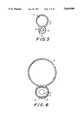
- FIG. 5is a cross-sectional view in the proximal direction of the embodiment shown in FIG. 4;
- FIG. 6is a cross-sectional view through the balloon of the embodiment shown in FIG. 4;
- FIGS. 7 and 8are representations of cross-sections of dilatation balloon catheters according to the prior art and the invention, respectively, within a stricture to be dilated.
- FIG. 9is a cross-sectional view of the distal portion of another embodiment of the invention.
- FIG. 10is a longitudinal cross-sectional view of a further embodiment of the invention.
- FIG. 11is a cross-sectional view of the line 11--11 of the embodiment shown in FIG. 10;
- FIG. 12is a longitudinal cross-sectional view of a yet further embodiment of the invention.
- FIG. 13is a longitudinal cross-section view of another embodiment of the invention.
- FIG. 14is a cross-sectional view of the line 14--14 of the embodiment shown in FIG. 13;
- FIG. 15is a cross-sectional view of a modification of the embodiment shown in FIG. 4;
- FIG. 16is a cross-sectional view of a modification of the embodiment shown in FIG. 12.
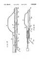
- FIGS. 17 and 18,are schematic cross-sectional views of a stent delivery system according to the invention.
- the balloon of a balloon dilatation catheteris mounted eccentric to the catheter shaft, and/or the distal section of the guidewire lumen.
- the distal section of the cathetercomprises two or more substantially coextensive lumens wherein the distal portion of one lumen terminates in a dilatation balloon.
- Another, second lumenhas proximal and distal openings to receive a guidewire in a sliding fit.
- the second lumenmay be of substantially equivalent length to the first lumen, or, alternatively, be shorter, such that the proximal opening of the second lumen is substantially distal to the proximal opening of the first lumen.
- the cathetercomprises two substantially coextensive lumens of equal length, wherein the distal portion of one lumen terminates in a dilatation balloon, and the second lumen is open at its distal end and is interrupted near its distal end to provide an opening for a guidewire that extends distally through the open distal end.
- the second lumenmay have a pushing wire that extends from the proximal portion of the catheter to a point proximal, adjacent, or distal to the opening.
- the second lumenengages a radiopaque marker that functions to help break plaque as well as to provide means for locating the position of the catheter balloon within the vessel.
- FIGS. 3 and 3adepict the distal portion of a balloon dilatation catheter 1 having coextensively extending lumens 2 and 3.
- Lumen 2terminates in a dilatation balloon 4 which is inflated and deflated through lumen 2.
- Lumen 3may be bonded to balloon 4 as shown in FIG. 3a or preferably formed from one piece as shown in FIG. 3.
- lumen 3contains pushing wire 5, which extends from the proximal end (not shown) of catheter 1 to a position 6 proximal, adjacent to, or within balloon 4.
- the distal portion of pushing wire 5is secured by closure, e.g., heat-shrinking of lumen 3, by insertion of a plug, or by other holding or fixation means.
- the distal portion 7 of pushing wire 5is preferably tapered distally to provide a smooth transition in axial stiffness.
- the pushing wire 5will become less stiff as the diameter of pushing wire 5 narrows in the distal direction.
- the taperingis substantially linear over the distal portion of the pushing wire 5.
- the taperingmay be stepped, in discrete reductions, or otherwise nonlinear.
- the distal portion 10 of lumen 3is enlarged, beginning at a location proximal to the balloon 4. Opening 9 allows a guidewire 8 to enter and extend distally through the open distal end of lumen 3.
- a lubricious lining 14 and a radiopaque marker 15are included in the enlarged section 10.
- Lubricious lining 14may function to hold the distal portion of pushing wire 5 between the inner surface of lumen 3 and the outer surface of lubricious lining 14.
- Optionally lining 14could comprise a metal or polymeric coil with a lubricious lining.
- FIG. 5represents a cross-sectional view showing how lumens 2 and 3 relate to one another and how pushing wire 5 is positioned within lumen 3.
- Lumen walls 12 and 13can each have a thickness of from about 0.3 to 20 mil, preferably from about 0.5 to 10 mil.
- FIG. 6represents a cross-sectional view through the center of the balloon of this embodiment. This figure shows how the balloon relates to the enlarged section 10 of lumen 3, and to guidewire 8.
- a radiopaque marker 15is sandwiched between the outer surface of lubricious lining 14 and the inner surface of the wall of enlarged section 10.
- the cathetermay have more than one external lumen, preferably two.
- FIGS. 5 and 6each appear to represent a one-piece construction, as shown in FIG. 3a, lumens 2 and 3 may be defined by tubes adhesively or otherwise bonded together.
- FIGS. 7 and 8show dilatation balloon catheters, according to the prior art and the invention, respectively, in the application of dilating a stenotic lesion 40 in a blood vessel 41.
- Fforce
- the pressure that is exerted against the lesionis proportional to this force, F, divided by the area upon which the force is acting (the "contact area").
- the contact areais equal to the lateral surface area of the balloon 42.
- the contact areais not coextensive with the lateral surface area of the balloon 4.
- the contact areais equal to the lateral surface area of balloon 4. However, at another point, the contact area is equal to the lateral surface area of the tube that defines lumen 3. Since lumen 3 has a much smaller area of contact against the lesion than does the balloon 4, the pressure exerted at that point is much greater. Therefore, unnecessarily high balloon inflation pressures can be avoided since this design accentuates and focuses the radial force against the lesion adjacent to lumen 3.
- the pressure exerted against the portion of the lesion adjacent lumen 3is greater than that exerted against the portion of the lesion adjacent to the balloon.
- FIGS. 9 to 11, 13, and 14provide for alternate means to achieve the concentration or focusing of the dilating force.
- the section in the eccentric lumen 3 that is associated with the dilatation, i.e., adjacent to the balloon,has means that form an even smaller contact area with the lesion.
- Such meansprovide somewhat of a sharp edge, similar to a knife edge, to cut the lesion as the balloon is inflated.
- the metal band 17 that serves as a radiopaque markerhas a triangular shape, and is positioned within lumen 3 such that one side of the triangle 17 is located under the balloon, and the opposite apex of the triangle is against the lesion.
- FIGS. 9illustrates the embodiment of FIGS.
- a section of lumen 3 under the balloonis cut away.
- a triangularly shaped wire or guidewire, or some other knife edge or cutting instrument 19,can be safely passed through lumen 3 and positioned directly at the lesion through the opening 18. This opening in lumen 3 will also allow drugs to be delivered directly to the lesion.
- FIGS. 13 and 14Another embodiment of the invention is shown in FIGS. 13 and 14, where lumen 43 contains pushing wire 45, which extends from the proximal end (not shown) of catheter 41 to a position 46 proximal, adjacent to, or within dilatation balloon 44.
- the distal portion of pushing wire 45is secured by closure, e.g., heat-shrinking of lumen of lumen 43, by insertion of a plug, or by other holding or fixation means.
- the distal portion 50 of lumen 43is enlarged, beginning at a location proximal to the balloon 44. Opening 49 allows guidewire 48 to enter and extend distally through the open distal end 47 of lumen 43.
- Enlarged section 50contains a rigid or substantially rigid, lubricious liner 51 of triangular shape, where one corner of liner 51 extends radially away from balloon 44.
- liner 51will be of uniform cross-section, the cross-section being an equilateral or isosceles triangle, with a flat surface adjacent balloon 44.
- the triangular-shaped liner 51will function to focus the dilatation forces, as explained above for FIG. 8.
- liner 51may optionally function to hold the distal portion of pushing wire 45 between the inner surface of lumen 43 and the outer surface of liner 51.
- the rapid exchange embodiment of the inventioncan also function as an improved, more efficient perfusion catheter.
- bloodWith the guidewire removed from lumen 3, blood will flow through lumen 3 while the balloon is inflated. Since the openings in lumen 3 are collinear with the artery, i.e., collinear with the direction of the flow of blood, and are large (compared to the side-hole openings of previously described perfusion catheters), there will be significantly less turbulence in the blood flow through lumen 3. As a result, there will be significantly greater blood flow, and reduced hemolysis compared to previously described perfusion catheters.
- a guidewiremay be left in place (i.e., in a lumen) while blood flows through an open lumen.
- FIGS. 15 and 16have the ability to exhibit rapid/single operator exchange capability while functioning as perfusion catheters.
- the catheter shaftcomprises inflation lumen 62, for balloon 4, and second lumen 63, which extends proximally from its distal opening 64.
- a guidewire 66slidably fits within lumen 63, extending from proximal opening 68 through distal opening 64.
- the distal end of a push wire 65is secured against the wall surface 70 separating lumens 62 and 63 by lubricious lining 72.
- Enlarged portion 73 of lumen 63optionally has a radiopaque marker 75.
- a perfusion opening 76corresponds to a transition from enlarged portion 73 to less enlarged portion 78. Perfusion can occur with guidewire 66 in place in lumen 63 or when guidewire 66 is partly or wholly withdrawn proximally. Guidewire 66 could be withdrawn partly so that its distal portion still remained within less enlarged portion 78 and then advanced distally when desired.
- the catheter shafthas inflation lumen 82 and lumen 83, which extends from proximal opening 85 to distal opening 86.
- Guidewire 88extends into lumen 83 through opening 85.
- Lumen 83comprises enlarged portion 89 and less enlarged portion 90.
- Perfusion opening 92is positioned at or about the transition from enlarged portion 89 to less enlarged portion 90. Perfusion can occur with guidewire 88 in place in lumen 83 or when guidewire 88 is partly or wholly withdrawn from lumen 83.
- Guidewire 88could be withdrawn partly so that its distal portion still remains in less enlarged portion 90 and then can be advanced distally.
- the distal section of a balloon dilatation cathetercomprises at least two substantially, longitudinal coextensive lumens wherein one lumen terminates in a dilatation balloon and at least one other lumen is positioned outside, i.e., eccentric to the balloon.
- the lumen walls 12 and 13are comprised of materials conventional to balloon dilatation catheters. Suitable materials include polyolefins such as polyethylene, polyethylene terepthalate, polyurethanes, polyesters, and various copolymers thereof.
- pushing wire 5can be made from any rigid, medically acceptable material suitable for such use, including, but not limited to wires or hypotubes comprised of stainless steel or other rigid materials.
- the construction according to the inventionleads to flexibility in product design.
- the choice of pushing wireallows the designer to impart various features to the catheter in the form of various flexibility and pushability combinations.
- a hollow pushing wire, or deletion or removal of the pushing wirewould facilitate infusion of fluids, drugs, and/or contrast media through the catheter into the distal vasculature.
- lumen 2, used to inflate the ballooncould have a composite structure, for example, with a distal segment coextensive with lumen 3 as described above, and a proximal segment made from a hollow wire, such as a hypotube 50. An example of such an embodiment is shown in FIG. 12.
- catheter 1may have at least one additional, coextensive lumen that would similarly facilitate infusion of liquids, drugs and/or contrast media.
- a catheter 1 with a third, coextensive lumen open at its distal endcould have several possible applications.
- Lumen 3 or 43, and/or respective distal portions 10 or 50,can be sufficiently rigid to maintain a lumen for perfusion when dilatation balloon 4 or 44 is inflated. Rigidity may be effected by various methods known in the art, such as, for example, material selection, geometric configuration, a liner, a coiled wire, etc.
- a lubricious coating or a section of thin tubing 14 of lubricious materialis sealed into enlarged section 10.
- a lubricious coating or a section of thin tubing 14 of lubricious materialis sealed into enlarged section 10.
- materials suitable for this purposesuch as polytetrafluoroethylene (available as TEFLON® from dupont), polyethylenes, polysiloxanes, etc.
- the tubing section 14can hold the distal portion 7 of pushing wire 5, as well as radiopaque marker 15 or 17, in position.
- a slitting means(not shown) is mounted proximally on guidewire 8. Then, as the catheter 1 is withdrawn, the enlarged section engages the slitting means, the enlarged section 10 is slit, and catheter 1 is separated from guidewire 8. This would eliminate the requirement for the operator to change hands as catheter 1 is removed.
- the catheter 1may have visual length markings along its shaft that would enable the operator to predict when the catheter 1 would exit the guiding catheter into the vasculature. This would reduce the fluoroscope time.
- the preferred designwould put the markings directly on the pushing wire 5 (heat shrink tubing rings, inks, paints, etc.). Since pushing wire 5 is encapsulated within the second lumen 3, the markings would not be exposed to the patient (i.e., markings would not come off, and materials which could be toxic if exposed may be used).
- preparation of a catheter 1 according to the inventioncan be carried out by methods and techniques known to or discernible by those skilled in the art. Furthermore, preparation of a catheter 1 is described and taught in Applicant's co-pending, commonly assigned, U.S. patent application Ser. No. 07/969,946, filed Oct. 30, 1992, and U.S. patent application Ser. No. 08/087,428, filed Jul. 2, 1993, both of which are incorporated herein by reference.
- Guidewire 8may be a conventional guidewire, preferably a spring guidewire, as is well known. Typical guidewires are shown in U.S. Pat. Nos. 4,757,827, 4,815,478, 4,813,434, 4,619,274, 4,554,929, 4,545,390, 4,538,622, 3,906,938, 3,973,556, and 4,719,924, all of which are incorporated herein by reference.
- the shaft of guidewire 8could be solid or hollow, such as a hypotube, with an open distal end, to facilitate drug infusion.
- a guiding catheteris inserted into the coronary artery in a conventional manner.
- the guidewire 8is then introduced into the guiding catheter and advanced to and across the lesion.
- the balloon dilatation catheteris inserted onto the guidewire and then advanced along the guidewire 8 to and across the lesion.
- the balloon 4After the balloon 4 has crossed the stenosis or lesion, the balloon 4 can be inflated in a conventional manner by introducing a radiopaque contrast liquid through the lumen 2. After the inflation has occurred and the desired operation has been performed by enlarging the opening in the stenosis, the balloon dilatation catheter 1 can be removed very rapidly by holding the guidewire 8 stationary and withdrawing the balloon dilation catheter.
- the balloon dilatation cathetercan be removed and thereafter the guiding catheter can be removed.
- the eccentric balloon dilatation cathetercan be used to deliver to a desired site, e.g., within a patient's body, a "balloon expandable" stent.
- a desired sitee.g., within a patient's body
- a "balloon expandable" stentSuch stents are known in the art, as evidenced by, for example, U.S. Pat. Nos. 4,733,665, 4,739,762, 4,776,337, 4,800,882, 4,856,516, 4,878,906, 4,886,062, 4,969,458, 5,037,392, 5,133,732, 5,158,548, 5,161, 547, 5,258,020, 5,266,073, 5,382,261, and 5,403,341, all of which are incorporated herein by reference.
- the eccentric balloon catheter described hereinis especially suitable for delivering such stents because the eccentric balloon tends to retain its position relative to the catheter shaft and increases the likelihood of more accurate positioning (the accordion effect shown in FIG. 1 is an example of the movement that could occur with a concentric balloon design for a stent delivery catheter.)
- the focused force aspects of the eccentric dilatation balloon designare believed to be more effective in expanding or opening some types of balloon expandable stents than concentric balloon catheter would be.
- the stent in its non-expanded configurationis positioned around the deflated eccentric balloon at the distal portion of the catheter shaft. Then, the distal portion of the catheter is advanced percutaneously through a guide catheter, optionally over a guidewire, to a desired site, e.g., adjacent or across a stenosis or across a segment where an stenosis was removed or treated.
- the balloonis expanded to expand the stent, the balloon is deflated, and the catheter is removed proximally.
- FIGS. 17 and 18A representative embodiment of the stent delivery system can been seen in FIGS. 17 and 18.
- the balloonis inflated, as shown in FIG. 18, the stent 100 expands or dilates, causing the opening in stenosis 106 to dilate as well.
- Balloon 102is then deflated and the catheter is removed proximally, leaving expanded stent 100 in place across stenosis 106.
Landscapes
- Health & Medical Sciences (AREA)
- Heart & Thoracic Surgery (AREA)
- Engineering & Computer Science (AREA)
- Biomedical Technology (AREA)
- Life Sciences & Earth Sciences (AREA)
- Veterinary Medicine (AREA)
- Animal Behavior & Ethology (AREA)
- Public Health (AREA)
- General Health & Medical Sciences (AREA)
- Cardiology (AREA)
- Oral & Maxillofacial Surgery (AREA)
- Vascular Medicine (AREA)
- Transplantation (AREA)
- Child & Adolescent Psychology (AREA)
- Biophysics (AREA)
- Pulmonology (AREA)
- Anesthesiology (AREA)
- Hematology (AREA)
- Media Introduction/Drainage Providing Device (AREA)
Abstract
Description
A.sub.B =CA.sub.L3 (4)
Claims (43)
Priority Applications (4)
| Application Number | Priority Date | Filing Date | Title |
|---|---|---|---|
| US08/491,136US5669880A (en) | 1993-08-24 | 1995-06-16 | Stent delivery system |
| CA002197461ACA2197461C (en) | 1995-06-16 | 1996-06-13 | Stent delivery system |
| PCT/US1996/010345WO1997000094A1 (en) | 1993-08-24 | 1996-06-13 | Stent delivery system |
| EP96919432AEP0785807A4 (en) | 1995-06-16 | 1996-06-13 | Stent delivery system |
Applications Claiming Priority (3)
| Application Number | Priority Date | Filing Date | Title |
|---|---|---|---|
| US08/111,304US5413557A (en) | 1993-08-24 | 1993-08-24 | Dilatation catheter with eccentric balloon |
| US08/418,536US5569199A (en) | 1993-08-24 | 1995-04-07 | Dilatation catheter with eccentric balloon |
| US08/491,136US5669880A (en) | 1993-08-24 | 1995-06-16 | Stent delivery system |
Related Parent Applications (1)
| Application Number | Title | Priority Date | Filing Date |
|---|---|---|---|
| US08/418,536Continuation-In-PartUS5569199A (en) | 1993-08-24 | 1995-04-07 | Dilatation catheter with eccentric balloon |
Publications (1)
| Publication Number | Publication Date |
|---|---|
| US5669880Atrue US5669880A (en) | 1997-09-23 |
Family
ID=56289694
Family Applications (1)
| Application Number | Title | Priority Date | Filing Date |
|---|---|---|---|
| US08/491,136Expired - LifetimeUS5669880A (en) | 1993-08-24 | 1995-06-16 | Stent delivery system |
Country Status (2)
| Country | Link |
|---|---|
| US (1) | US5669880A (en) |
| WO (1) | WO1997000094A1 (en) |
Cited By (70)
| Publication number | Priority date | Publication date | Assignee | Title |
|---|---|---|---|---|
| WO1999048439A1 (en)* | 1997-03-13 | 1999-09-30 | Solar Ronald J | Hydraulic method and apparatus for uniform radial compression and catheter mounting of radially expandable intraluminal stents and stented grafts |
| US6248100B1 (en) | 1997-08-14 | 2001-06-19 | Scimed Life Systems, Inc. | Drainage catheter delivery system |
| US6264624B1 (en) | 1997-08-14 | 2001-07-24 | Boston Scientific Coporation | Drainage catheter delivery system |
| WO2001060284A1 (en)* | 2000-02-18 | 2001-08-23 | E.V.R. Endovascular Researches S.A. | Endolumenal device for delivering and deploying an endolumenal expandable prosthesis |
| US6287314B1 (en)* | 1998-04-21 | 2001-09-11 | Advanced Cardiovascular Systems, Inc. | Stent deploying catheter system |
| US6440161B1 (en) | 1999-07-07 | 2002-08-27 | Endologix, Inc. | Dual wire placement catheter |
| US6500202B1 (en) | 1998-12-11 | 2002-12-31 | Endologix, Inc. | Bifurcation graft deployment catheter |
| US6508835B1 (en) | 1998-12-11 | 2003-01-21 | Endologix, Inc. | Endoluminal vascular prosthesis |
| US20030114912A1 (en)* | 2000-05-30 | 2003-06-19 | Jacques Sequin | Endoprosthesis deployment system for treating vascular bifurcations |
| US20030120208A1 (en)* | 2001-11-08 | 2003-06-26 | Houser Russell A. | Rapid exchange catheter with stent deployment, therapeutic infusion, and lesion sampling features |
| US20030191436A1 (en)* | 2002-04-05 | 2003-10-09 | Horvers Ronald Adrianus Maria | Balloon catheter |
| US6660030B2 (en) | 1998-12-11 | 2003-12-09 | Endologix, Inc. | Bifurcation graft deployment catheter |
| US20040006381A1 (en)* | 2000-05-30 | 2004-01-08 | Jacques Sequin | Noncylindrical drug eluting stent for treating vascular bifurcations |
| US20040073239A1 (en)* | 2001-01-26 | 2004-04-15 | Takasumi Nakamura | Blood vessel anastomosing auxiliary tool |
| US6733523B2 (en) | 1998-12-11 | 2004-05-11 | Endologix, Inc. | Implantable vascular graft |
| US6743219B1 (en) | 2000-08-02 | 2004-06-01 | Cordis Corporation | Delivery apparatus for a self-expanding stent |
| US20050119686A1 (en)* | 2003-12-01 | 2005-06-02 | Clubb Thomas L. | Rapid exchange catheters with tandem lumens |
| US20050154440A1 (en)* | 2004-01-13 | 2005-07-14 | Limon Timothy A. | Balloon catheter having a textured member for enhancing balloon or stent retention |
| US6951572B1 (en) | 1997-02-20 | 2005-10-04 | Endologix, Inc. | Bifurcated vascular graft and method and apparatus for deploying same |
| US6953431B2 (en) | 2002-04-11 | 2005-10-11 | University Of South Florida | Eccentric dilation balloons for use with endoscopes |
| US20060036309A1 (en)* | 2002-02-28 | 2006-02-16 | Counter Clockwise, Inc. | Guidewire loaded stent for delivery through a catheter |
| US20070005099A1 (en)* | 2005-06-30 | 2007-01-04 | Jones Donald K | Chemically based vascular occlusion device deployment |
| US7169170B2 (en) | 2002-02-22 | 2007-01-30 | Cordis Corporation | Self-expanding stent delivery system |
| US20070213663A1 (en)* | 1995-03-02 | 2007-09-13 | Boston Scientific Scimed, Inc. | Balloon catheter with molded stepped balloon |
| US20070265564A1 (en)* | 2006-05-15 | 2007-11-15 | Medtronic Vascular, Inc. | Catheter Having Non-Blood-Contacting Exit Markers |
| US20080082050A1 (en)* | 2006-05-11 | 2008-04-03 | Solar Ronald J | Systems and methods for treating a vessel using focused force |
| US20080300667A1 (en)* | 2007-05-31 | 2008-12-04 | Bay Street Medical | System for delivering a stent |
| US20090143728A1 (en)* | 2007-11-30 | 2009-06-04 | Numed, Inc. | Balloon catheter with safety feature |
| US20100234800A1 (en)* | 2004-03-04 | 2010-09-16 | Y Med, Inc. | Vessel treatment devices |
| US20100241212A1 (en)* | 2004-03-04 | 2010-09-23 | Y Med, Inc. | Vessel treatment devices |
| US20100286720A1 (en)* | 2004-03-04 | 2010-11-11 | Y Med, Inc. | Vessel treatment devices |
| US20110034949A1 (en)* | 2006-05-11 | 2011-02-10 | Y-Med, Inc. | Systems and methods for treating a vessel using focused force |
| US7892469B2 (en) | 1998-04-21 | 2011-02-22 | Advanced Cardiovascular Systems, Inc. | Method of making a non-compliant balloon for a catheter |
| US20110077622A1 (en)* | 2009-09-25 | 2011-03-31 | Boston Scientific Scimed, Inc. | Delivery system having stent locking structure |
| US20110160739A1 (en)* | 2009-12-30 | 2011-06-30 | Boston Scientific Scimed, Inc. | Rotatable Connection Between a Tubular Member and an Elongate Wire of a Catheter |
| US20110190708A1 (en)* | 2004-03-04 | 2011-08-04 | YMED, Inc. | Positioning device for ostial lesions |
| US8167925B2 (en) | 1999-03-11 | 2012-05-01 | Endologix, Inc. | Single puncture bifurcation graft deployment system |
| US8216295B2 (en) | 2008-07-01 | 2012-07-10 | Endologix, Inc. | Catheter system and methods of using same |
| US8231667B2 (en) | 2002-11-08 | 2012-07-31 | Jacques Séguin | Endoprosthesis for vascular bifurcation |
| US8236040B2 (en) | 2008-04-11 | 2012-08-07 | Endologix, Inc. | Bifurcated graft deployment systems and methods |
| US8414635B2 (en) | 1999-02-01 | 2013-04-09 | Idev Technologies, Inc. | Plain woven stents |
| US8419788B2 (en) | 2006-10-22 | 2013-04-16 | Idev Technologies, Inc. | Secured strand end devices |
| US8523931B2 (en) | 2007-01-12 | 2013-09-03 | Endologix, Inc. | Dual concentric guidewire and methods of bifurcated graft deployment |
| US8808350B2 (en) | 2011-03-01 | 2014-08-19 | Endologix, Inc. | Catheter system and methods of using same |
| US8821564B2 (en) | 2009-07-27 | 2014-09-02 | Endologix, Inc. | Stent graft |
| US8876881B2 (en) | 2006-10-22 | 2014-11-04 | Idev Technologies, Inc. | Devices for stent advancement |
| US20150005805A1 (en)* | 2013-03-15 | 2015-01-01 | Acclarent, Inc. | Uncinate process support for ethmoid infundibulum illumination |
| US9023095B2 (en) | 2010-05-27 | 2015-05-05 | Idev Technologies, Inc. | Stent delivery system with pusher assembly |
| US20150133780A1 (en)* | 2013-03-08 | 2015-05-14 | Endobar Solutions, LLC | Selectively Delivering Particles into the Distal Portion of the Left Gastric Artery |
| US9095465B2 (en) | 2012-12-20 | 2015-08-04 | Sanford Health | Stent deployment device and methods for use |
| US9101501B2 (en) | 1996-06-06 | 2015-08-11 | Biosensors International Group, Ltd. | Bifurcation stent and method of positioning in a body lumen |
| US9233015B2 (en) | 2012-06-15 | 2016-01-12 | Trivascular, Inc. | Endovascular delivery system with an improved radiopaque marker scheme |
| US9265637B2 (en) | 2010-11-19 | 2016-02-23 | Boston Scientific Scimed, Inc. | Rapid exchange stent delivery system |
| US9339631B2 (en) | 2009-09-25 | 2016-05-17 | Boston Scientific Scimed, Inc. | Locking mechanism for a medical device |
| US9393100B2 (en) | 2010-11-17 | 2016-07-19 | Endologix, Inc. | Devices and methods to treat vascular dissections |
| JP2016220861A (en)* | 2015-05-28 | 2016-12-28 | 日本ライフライン株式会社 | Balloon catheter |
| CN106310495A (en)* | 2016-08-22 | 2017-01-11 | 苗立夫 | Perfusion and dilation balloon system |
| US9579103B2 (en) | 2009-05-01 | 2017-02-28 | Endologix, Inc. | Percutaneous method and device to treat dissections |
| US9615959B2 (en) | 2013-03-15 | 2017-04-11 | Acclarent, Inc. | Uncinate process support for ethmoid infundibulum illumination |
| US9757262B2 (en) | 2009-07-15 | 2017-09-12 | Endologix, Inc. | Stent graft |
| US10245166B2 (en) | 2008-02-22 | 2019-04-02 | Endologix, Inc. | Apparatus and method of placement of a graft or graft system |
| US10603196B2 (en) | 2009-04-28 | 2020-03-31 | Endologix, Inc. | Fenestrated prosthesis |
| US10772717B2 (en) | 2009-05-01 | 2020-09-15 | Endologix, Inc. | Percutaneous method and device to treat dissections |
| WO2020219265A1 (en)* | 2019-04-22 | 2020-10-29 | Edwards Lifesciences Corporation | Anchor for transcatheter access into the coronary sinus |
| US10849771B2 (en) | 2011-06-27 | 2020-12-01 | Boston Scientific Scimed, Inc. | Stent delivery systems and methods for making and using stent delivery systems |
| US11129737B2 (en) | 2015-06-30 | 2021-09-28 | Endologix Llc | Locking assembly for coupling guidewire to delivery system |
| US11406518B2 (en) | 2010-11-02 | 2022-08-09 | Endologix Llc | Apparatus and method of placement of a graft or graft system |
| US12274467B2 (en) | 2019-12-20 | 2025-04-15 | Kaneka Corporation | Balloon catheter |
| US12408907B1 (en) | 2019-11-14 | 2025-09-09 | Edwards Lifesciences Corporation | Method of reducing left atrial pressure |
| US12414797B2 (en) | 2019-08-22 | 2025-09-16 | Edwards Lifesciences Corporation | Puncture needles |
Citations (17)
| Publication number | Priority date | Publication date | Assignee | Title |
|---|---|---|---|---|
| US3811448A (en)* | 1972-10-25 | 1974-05-21 | A Morton | Urinary drainage catheter |
| US4195637A (en)* | 1977-10-21 | 1980-04-01 | Schneider Medintag Ag | Catheter arrangement, method of catheterization, and method of manufacturing a dilatation element |
| US4323071A (en)* | 1978-04-24 | 1982-04-06 | Advanced Catheter Systems, Inc. | Vascular guiding catheter assembly and vascular dilating catheter assembly and a combination thereof and methods of making the same |
| US4493711A (en)* | 1982-06-25 | 1985-01-15 | Thomas J. Fogarty | Tubular extrusion catheter |
| US4573470A (en)* | 1984-05-30 | 1986-03-04 | Advanced Cardiovascular Systems, Inc. | Low-profile steerable intraoperative balloon dilitation catheter |
| US4641649A (en)* | 1985-10-30 | 1987-02-10 | Rca Corporation | Method and apparatus for high frequency catheter ablation |
| US4643186A (en)* | 1985-10-30 | 1987-02-17 | Rca Corporation | Percutaneous transluminal microwave catheter angioplasty |
| US4762129A (en)* | 1984-11-23 | 1988-08-09 | Tassilo Bonzel | Dilatation catheter |
| US4790315A (en)* | 1986-09-02 | 1988-12-13 | Advanced Cardiovascular Systems, Inc. | Perfusion dilatation catheter and method of manufacture |
| US5040548A (en)* | 1989-06-01 | 1991-08-20 | Yock Paul G | Angioplasty mehtod |
| US5045061A (en)* | 1990-02-02 | 1991-09-03 | C. R. Bard, Inc. | Balloon catheter and locking guidewire system |
| US5061273A (en)* | 1989-06-01 | 1991-10-29 | Yock Paul G | Angioplasty apparatus facilitating rapid exchanges |
| US5090958A (en)* | 1988-11-23 | 1992-02-25 | Harvinder Sahota | Balloon catheters |
| US5439446A (en)* | 1994-06-30 | 1995-08-08 | Boston Scientific Corporation | Stent and therapeutic delivery system |
| US5507768A (en)* | 1991-01-28 | 1996-04-16 | Advanced Cardiovascular Systems, Inc. | Stent delivery system |
| US5545135A (en)* | 1994-10-31 | 1996-08-13 | Boston Scientific Corporation | Perfusion balloon stent |
| US5593412A (en)* | 1994-03-01 | 1997-01-14 | Cordis Corporation | Stent delivery method and apparatus |
- 1995
- 1995-06-16USUS08/491,136patent/US5669880A/ennot_activeExpired - Lifetime
- 1996
- 1996-06-13WOPCT/US1996/010345patent/WO1997000094A1/ennot_activeApplication Discontinuation
Patent Citations (19)
| Publication number | Priority date | Publication date | Assignee | Title |
|---|---|---|---|---|
| US3811448A (en)* | 1972-10-25 | 1974-05-21 | A Morton | Urinary drainage catheter |
| US4195637A (en)* | 1977-10-21 | 1980-04-01 | Schneider Medintag Ag | Catheter arrangement, method of catheterization, and method of manufacturing a dilatation element |
| US4323071A (en)* | 1978-04-24 | 1982-04-06 | Advanced Catheter Systems, Inc. | Vascular guiding catheter assembly and vascular dilating catheter assembly and a combination thereof and methods of making the same |
| US4323071B1 (en)* | 1978-04-24 | 1990-05-29 | Advanced Cardiovascular System | |
| US4493711A (en)* | 1982-06-25 | 1985-01-15 | Thomas J. Fogarty | Tubular extrusion catheter |
| US4573470A (en)* | 1984-05-30 | 1986-03-04 | Advanced Cardiovascular Systems, Inc. | Low-profile steerable intraoperative balloon dilitation catheter |
| US4762129B1 (en)* | 1984-11-23 | 1991-07-02 | Tassilo Bonzel | |
| US4762129A (en)* | 1984-11-23 | 1988-08-09 | Tassilo Bonzel | Dilatation catheter |
| US4641649A (en)* | 1985-10-30 | 1987-02-10 | Rca Corporation | Method and apparatus for high frequency catheter ablation |
| US4643186A (en)* | 1985-10-30 | 1987-02-17 | Rca Corporation | Percutaneous transluminal microwave catheter angioplasty |
| US4790315A (en)* | 1986-09-02 | 1988-12-13 | Advanced Cardiovascular Systems, Inc. | Perfusion dilatation catheter and method of manufacture |
| US5090958A (en)* | 1988-11-23 | 1992-02-25 | Harvinder Sahota | Balloon catheters |
| US5040548A (en)* | 1989-06-01 | 1991-08-20 | Yock Paul G | Angioplasty mehtod |
| US5061273A (en)* | 1989-06-01 | 1991-10-29 | Yock Paul G | Angioplasty apparatus facilitating rapid exchanges |
| US5045061A (en)* | 1990-02-02 | 1991-09-03 | C. R. Bard, Inc. | Balloon catheter and locking guidewire system |
| US5507768A (en)* | 1991-01-28 | 1996-04-16 | Advanced Cardiovascular Systems, Inc. | Stent delivery system |
| US5593412A (en)* | 1994-03-01 | 1997-01-14 | Cordis Corporation | Stent delivery method and apparatus |
| US5439446A (en)* | 1994-06-30 | 1995-08-08 | Boston Scientific Corporation | Stent and therapeutic delivery system |
| US5545135A (en)* | 1994-10-31 | 1996-08-13 | Boston Scientific Corporation | Perfusion balloon stent |
Cited By (144)
| Publication number | Priority date | Publication date | Assignee | Title |
|---|---|---|---|---|
| US20070213663A1 (en)* | 1995-03-02 | 2007-09-13 | Boston Scientific Scimed, Inc. | Balloon catheter with molded stepped balloon |
| US8728143B2 (en) | 1996-06-06 | 2014-05-20 | Biosensors International Group, Ltd. | Endoprosthesis deployment system for treating vascular bifurcations |
| US8603157B2 (en) | 1996-06-06 | 2013-12-10 | Biosensors International Group, Ltd. | Endoprosthesis deployment methods for treating vascular bifurcations |
| US9101501B2 (en) | 1996-06-06 | 2015-08-11 | Biosensors International Group, Ltd. | Bifurcation stent and method of positioning in a body lumen |
| US6951572B1 (en) | 1997-02-20 | 2005-10-04 | Endologix, Inc. | Bifurcated vascular graft and method and apparatus for deploying same |
| WO1999048439A1 (en)* | 1997-03-13 | 1999-09-30 | Solar Ronald J | Hydraulic method and apparatus for uniform radial compression and catheter mounting of radially expandable intraluminal stents and stented grafts |
| US6264624B1 (en) | 1997-08-14 | 2001-07-24 | Boston Scientific Coporation | Drainage catheter delivery system |
| US6248100B1 (en) | 1997-08-14 | 2001-06-19 | Scimed Life Systems, Inc. | Drainage catheter delivery system |
| US6562024B2 (en) | 1997-08-14 | 2003-05-13 | Scimed Life Systems, Inc. | Drainage catheter delivery system |
| US6287314B1 (en)* | 1998-04-21 | 2001-09-11 | Advanced Cardiovascular Systems, Inc. | Stent deploying catheter system |
| US6319259B1 (en)* | 1998-04-21 | 2001-11-20 | Advanced Cardiovascular Systems | Stent deploying catheter system |
| US6488688B2 (en) | 1998-04-21 | 2002-12-03 | Advanced Cardiovascular Systems, Inc. | Stent deploying catheter system and balloon catheter |
| US7892469B2 (en) | 1998-04-21 | 2011-02-22 | Advanced Cardiovascular Systems, Inc. | Method of making a non-compliant balloon for a catheter |
| US6953475B2 (en) | 1998-12-11 | 2005-10-11 | Endologix, Inc. | Bifurcation graft deployment catheter |
| US8147535B2 (en) | 1998-12-11 | 2012-04-03 | Endologix, Inc. | Bifurcation graft deployment catheter |
| US6660030B2 (en) | 1998-12-11 | 2003-12-09 | Endologix, Inc. | Bifurcation graft deployment catheter |
| US6500202B1 (en) | 1998-12-11 | 2002-12-31 | Endologix, Inc. | Bifurcation graft deployment catheter |
| US6508835B1 (en) | 1998-12-11 | 2003-01-21 | Endologix, Inc. | Endoluminal vascular prosthesis |
| US6733523B2 (en) | 1998-12-11 | 2004-05-11 | Endologix, Inc. | Implantable vascular graft |
| US8414635B2 (en) | 1999-02-01 | 2013-04-09 | Idev Technologies, Inc. | Plain woven stents |
| US8876880B2 (en) | 1999-02-01 | 2014-11-04 | Board Of Regents, The University Of Texas System | Plain woven stents |
| US8974516B2 (en) | 1999-02-01 | 2015-03-10 | Board Of Regents, The University Of Texas System | Plain woven stents |
| US9925074B2 (en) | 1999-02-01 | 2018-03-27 | Board Of Regents, The University Of Texas System | Plain woven stents |
| US8167925B2 (en) | 1999-03-11 | 2012-05-01 | Endologix, Inc. | Single puncture bifurcation graft deployment system |
| US6689157B2 (en) | 1999-07-07 | 2004-02-10 | Endologix, Inc. | Dual wire placement catheter |
| US6440161B1 (en) | 1999-07-07 | 2002-08-27 | Endologix, Inc. | Dual wire placement catheter |
| US20090299457A1 (en)* | 2000-02-18 | 2009-12-03 | Alessandro Lualdi | Endolumenal device for delivering and deploying an endolumenal expandable prosthesis |
| US20030187494A1 (en)* | 2000-02-18 | 2003-10-02 | Alessandro Loaldi | Endolumenal device for delivering and deploying an endolumenal expandable prosthesis |
| WO2001060284A1 (en)* | 2000-02-18 | 2001-08-23 | E.V.R. Endovascular Researches S.A. | Endolumenal device for delivering and deploying an endolumenal expandable prosthesis |
| KR100767848B1 (en) | 2000-02-18 | 2007-10-17 | 이.브이.알 엔도배스큘라 리서치스 에스.에이 | Intraluminal device for transporting and placing inflatable prosthetics in the lumen |
| US7540879B2 (en) | 2000-02-18 | 2009-06-02 | E.V.R. Endovascular Researches S.A. | Endolumenal device for delivering and deploying an endolumenal expandable prosthesis |
| AU2001237264B2 (en)* | 2000-02-18 | 2005-09-15 | EVR Medical S.a R.L. | Endolumenal device for delivering and deploying an endolumenal expandable prosthesis |
| US8012199B2 (en) | 2000-02-18 | 2011-09-06 | Alessandro Lualdi | Endolumenal device for delivering and deploying an endolumental expandable prosthesis |
| US7125419B2 (en) | 2000-05-30 | 2006-10-24 | Devax, Inc. | Noncylindrical stent deployment for treating vascular bifurcations |
| US8236041B2 (en) | 2000-05-30 | 2012-08-07 | Biosensors International Group, Ltd. | Noncylindrical stent deployment system for treating vascular bifurcations |
| US7238197B2 (en) | 2000-05-30 | 2007-07-03 | Devax, Inc. | Endoprosthesis deployment system for treating vascular bifurcations |
| US7344556B2 (en) | 2000-05-30 | 2008-03-18 | Devax, Inc. | Noncylindrical drug eluting stent for treating vascular bifurcations |
| US20040006381A1 (en)* | 2000-05-30 | 2004-01-08 | Jacques Sequin | Noncylindrical drug eluting stent for treating vascular bifurcations |
| US20030114912A1 (en)* | 2000-05-30 | 2003-06-19 | Jacques Sequin | Endoprosthesis deployment system for treating vascular bifurcations |
| US6743219B1 (en) | 2000-08-02 | 2004-06-01 | Cordis Corporation | Delivery apparatus for a self-expanding stent |
| US6773446B1 (en) | 2000-08-02 | 2004-08-10 | Cordis Corporation | Delivery apparatus for a self-expanding stent |
| US7632290B2 (en)* | 2001-01-26 | 2009-12-15 | Jms Co. Ltd. | Blood vessel anastomosing auxiliary tool |
| US20040073239A1 (en)* | 2001-01-26 | 2004-04-15 | Takasumi Nakamura | Blood vessel anastomosing auxiliary tool |
| US20030120208A1 (en)* | 2001-11-08 | 2003-06-26 | Houser Russell A. | Rapid exchange catheter with stent deployment, therapeutic infusion, and lesion sampling features |
| US7229431B2 (en) | 2001-11-08 | 2007-06-12 | Russell A. Houser | Rapid exchange catheter with stent deployment, therapeutic infusion, and lesion sampling features |
| US7169170B2 (en) | 2002-02-22 | 2007-01-30 | Cordis Corporation | Self-expanding stent delivery system |
| US8641748B2 (en) | 2002-02-28 | 2014-02-04 | Bay Street Medical, Inc. | Guidewire loaded stent for delivery through a catheter |
| US20070299502A1 (en)* | 2002-02-28 | 2007-12-27 | Counter Clockwise, Inc. | Guidewire loaded stent for delivery through a catheter |
| US20060116750A1 (en)* | 2002-02-28 | 2006-06-01 | Counter Clockwise, Inc. | Guidewire loaded stent for delivery through a catheter |
| US20060036309A1 (en)* | 2002-02-28 | 2006-02-16 | Counter Clockwise, Inc. | Guidewire loaded stent for delivery through a catheter |
| US9114038B2 (en)* | 2002-02-28 | 2015-08-25 | Back Bay Medical Inc. | Method of delivering a stent |
| US20030191436A1 (en)* | 2002-04-05 | 2003-10-09 | Horvers Ronald Adrianus Maria | Balloon catheter |
| US8298134B2 (en) | 2002-04-11 | 2012-10-30 | University Of South Florida | Eccentric dilation balloons for use with endoscopes |
| US20050288552A1 (en)* | 2002-04-11 | 2005-12-29 | Barthel James S | Eccentric dilation balloons for use with endoscopes |
| US6953431B2 (en) | 2002-04-11 | 2005-10-11 | University Of South Florida | Eccentric dilation balloons for use with endoscopes |
| US8864817B2 (en) | 2002-11-08 | 2014-10-21 | Jacques Séguin | Endoprosthesis for vascular bifurcation |
| US8231667B2 (en) | 2002-11-08 | 2012-07-31 | Jacques Séguin | Endoprosthesis for vascular bifurcation |
| US20050119686A1 (en)* | 2003-12-01 | 2005-06-02 | Clubb Thomas L. | Rapid exchange catheters with tandem lumens |
| US7695491B2 (en) | 2003-12-01 | 2010-04-13 | Ev3 Inc. | Rapid exchange catheters with tandem lumens |
| US20050154440A1 (en)* | 2004-01-13 | 2005-07-14 | Limon Timothy A. | Balloon catheter having a textured member for enhancing balloon or stent retention |
| US7316709B2 (en) | 2004-01-13 | 2008-01-08 | Advanced Cardiovascular Systems, Inc. | Balloon catheter having a textured member for enhancing balloon or stent retention |
| US20100241212A1 (en)* | 2004-03-04 | 2010-09-23 | Y Med, Inc. | Vessel treatment devices |
| US20100234800A1 (en)* | 2004-03-04 | 2010-09-16 | Y Med, Inc. | Vessel treatment devices |
| US9504473B2 (en) | 2004-03-04 | 2016-11-29 | Y Med Inc. | Vessel treatment devices |
| US11744723B2 (en) | 2004-03-04 | 2023-09-05 | Y Med, Inc. | Vessel treatment devices |
| US9050437B2 (en) | 2004-03-04 | 2015-06-09 | YMED, Inc. | Positioning device for ostial lesions |
| US20100286720A1 (en)* | 2004-03-04 | 2010-11-11 | Y Med, Inc. | Vessel treatment devices |
| US20110190708A1 (en)* | 2004-03-04 | 2011-08-04 | YMED, Inc. | Positioning device for ostial lesions |
| US7780695B2 (en)* | 2005-06-30 | 2010-08-24 | Codman & Shurtleff, Inc. | Chemically based vascular occlusion device deployment |
| US20070005099A1 (en)* | 2005-06-30 | 2007-01-04 | Jones Donald K | Chemically based vascular occlusion device deployment |
| US8206413B2 (en) | 2005-06-30 | 2012-06-26 | Codman & Shurtleff, Inc. | Chemically based vascular occlusion device deployment |
| US8262621B2 (en) | 2006-05-11 | 2012-09-11 | YMED, Inc. | Systems and methods for treating a vessel using focused force |
| US7901378B2 (en) | 2006-05-11 | 2011-03-08 | Y-Med, Inc. | Systems and methods for treating a vessel using focused force |
| US20090275920A1 (en)* | 2006-05-11 | 2009-11-05 | Solar Ronald J | Systems and methods for treating a vessel using focused force |
| US20110034949A1 (en)* | 2006-05-11 | 2011-02-10 | Y-Med, Inc. | Systems and methods for treating a vessel using focused force |
| US8486025B2 (en) | 2006-05-11 | 2013-07-16 | Ronald J. Solar | Systems and methods for treating a vessel using focused force |
| US20110118774A1 (en)* | 2006-05-11 | 2011-05-19 | YMED, Inc. | Systems and methods for treating a vessel using focused force |
| US20080082050A1 (en)* | 2006-05-11 | 2008-04-03 | Solar Ronald J | Systems and methods for treating a vessel using focused force |
| US8070729B2 (en) | 2006-05-11 | 2011-12-06 | YMED, Inc. | Systems and methods for treating a vessel using focused force |
| US20070265564A1 (en)* | 2006-05-15 | 2007-11-15 | Medtronic Vascular, Inc. | Catheter Having Non-Blood-Contacting Exit Markers |
| US9149374B2 (en) | 2006-10-22 | 2015-10-06 | Idev Technologies, Inc. | Methods for manufacturing secured strand end devices |
| US10470902B2 (en) | 2006-10-22 | 2019-11-12 | Idev Technologies, Inc. | Secured strand end devices |
| US9585776B2 (en) | 2006-10-22 | 2017-03-07 | Idev Technologies, Inc. | Secured strand end devices |
| US9629736B2 (en) | 2006-10-22 | 2017-04-25 | Idev Technologies, Inc. | Secured strand end devices |
| US9408730B2 (en) | 2006-10-22 | 2016-08-09 | Idev Technologies, Inc. | Secured strand end devices |
| US8739382B2 (en) | 2006-10-22 | 2014-06-03 | Idev Technologies, Inc. | Secured strand end devices |
| US8876881B2 (en) | 2006-10-22 | 2014-11-04 | Idev Technologies, Inc. | Devices for stent advancement |
| US9408729B2 (en) | 2006-10-22 | 2016-08-09 | Idev Technologies, Inc. | Secured strand end devices |
| US8966733B2 (en) | 2006-10-22 | 2015-03-03 | Idev Technologies, Inc. | Secured strand end devices |
| US8419788B2 (en) | 2006-10-22 | 2013-04-16 | Idev Technologies, Inc. | Secured strand end devices |
| US9895242B2 (en) | 2006-10-22 | 2018-02-20 | Idev Technologies, Inc. | Secured strand end devices |
| US8523931B2 (en) | 2007-01-12 | 2013-09-03 | Endologix, Inc. | Dual concentric guidewire and methods of bifurcated graft deployment |
| US20080300667A1 (en)* | 2007-05-31 | 2008-12-04 | Bay Street Medical | System for delivering a stent |
| US20090143728A1 (en)* | 2007-11-30 | 2009-06-04 | Numed, Inc. | Balloon catheter with safety feature |
| US10245166B2 (en) | 2008-02-22 | 2019-04-02 | Endologix, Inc. | Apparatus and method of placement of a graft or graft system |
| US8764812B2 (en) | 2008-04-11 | 2014-07-01 | Endologix, Inc. | Bifurcated graft deployment systems and methods |
| US8357192B2 (en) | 2008-04-11 | 2013-01-22 | Endologix, Inc. | Bifurcated graft deployment systems and methods |
| US8236040B2 (en) | 2008-04-11 | 2012-08-07 | Endologix, Inc. | Bifurcated graft deployment systems and methods |
| US9700701B2 (en) | 2008-07-01 | 2017-07-11 | Endologix, Inc. | Catheter system and methods of using same |
| US8216295B2 (en) | 2008-07-01 | 2012-07-10 | Endologix, Inc. | Catheter system and methods of using same |
| US10512758B2 (en) | 2008-07-01 | 2019-12-24 | Endologix, Inc. | Catheter system and methods of using same |
| US10603196B2 (en) | 2009-04-28 | 2020-03-31 | Endologix, Inc. | Fenestrated prosthesis |
| US9579103B2 (en) | 2009-05-01 | 2017-02-28 | Endologix, Inc. | Percutaneous method and device to treat dissections |
| US10772717B2 (en) | 2009-05-01 | 2020-09-15 | Endologix, Inc. | Percutaneous method and device to treat dissections |
| US9757262B2 (en) | 2009-07-15 | 2017-09-12 | Endologix, Inc. | Stent graft |
| US9907642B2 (en) | 2009-07-27 | 2018-03-06 | Endologix, Inc. | Stent graft |
| US8821564B2 (en) | 2009-07-27 | 2014-09-02 | Endologix, Inc. | Stent graft |
| US10874502B2 (en) | 2009-07-27 | 2020-12-29 | Endologix Llc | Stent graft |
| US9597207B2 (en) | 2009-09-25 | 2017-03-21 | Boston Scientific Scimed, Inc. | Delivery system having stent locking structure |
| US9339631B2 (en) | 2009-09-25 | 2016-05-17 | Boston Scientific Scimed, Inc. | Locking mechanism for a medical device |
| US8753303B2 (en) | 2009-09-25 | 2014-06-17 | Boston Scientific Scimed, Inc. | Delivery system having stent locking structure |
| US20110077622A1 (en)* | 2009-09-25 | 2011-03-31 | Boston Scientific Scimed, Inc. | Delivery system having stent locking structure |
| US20110160739A1 (en)* | 2009-12-30 | 2011-06-30 | Boston Scientific Scimed, Inc. | Rotatable Connection Between a Tubular Member and an Elongate Wire of a Catheter |
| US9408733B2 (en) | 2009-12-30 | 2016-08-09 | Michael Devon Amos | Rotatable connection between a tubular member and an elongate wire of a catheter |
| US12121460B2 (en) | 2010-05-27 | 2024-10-22 | Idev Technologies, Inc. | Stent delivery system with pusher assembly |
| US9023095B2 (en) | 2010-05-27 | 2015-05-05 | Idev Technologies, Inc. | Stent delivery system with pusher assembly |
| US11406518B2 (en) | 2010-11-02 | 2022-08-09 | Endologix Llc | Apparatus and method of placement of a graft or graft system |
| US9393100B2 (en) | 2010-11-17 | 2016-07-19 | Endologix, Inc. | Devices and methods to treat vascular dissections |
| US9265637B2 (en) | 2010-11-19 | 2016-02-23 | Boston Scientific Scimed, Inc. | Rapid exchange stent delivery system |
| US12239558B2 (en) | 2011-03-01 | 2025-03-04 | Endologix Llc | Catheter system and methods of using same |
| US9687374B2 (en) | 2011-03-01 | 2017-06-27 | Endologix, Inc. | Catheter system and methods of using same |
| US9549835B2 (en) | 2011-03-01 | 2017-01-24 | Endologix, Inc. | Catheter system and methods of using same |
| US10660775B2 (en) | 2011-03-01 | 2020-05-26 | Endologix, Inc. | Catheter system and methods of using same |
| US8808350B2 (en) | 2011-03-01 | 2014-08-19 | Endologix, Inc. | Catheter system and methods of using same |
| US10849771B2 (en) | 2011-06-27 | 2020-12-01 | Boston Scientific Scimed, Inc. | Stent delivery systems and methods for making and using stent delivery systems |
| US10034787B2 (en) | 2012-06-15 | 2018-07-31 | Trivascular, Inc. | Endovascular delivery system with an improved radiopaque marker scheme |
| US9233015B2 (en) | 2012-06-15 | 2016-01-12 | Trivascular, Inc. | Endovascular delivery system with an improved radiopaque marker scheme |
| US11013626B2 (en) | 2012-06-15 | 2021-05-25 | Trivascular, Inc. | Endovascular delivery system with an improved radiopaque marker scheme |
| US9095465B2 (en) | 2012-12-20 | 2015-08-04 | Sanford Health | Stent deployment device and methods for use |
| US20150133780A1 (en)* | 2013-03-08 | 2015-05-14 | Endobar Solutions, LLC | Selectively Delivering Particles into the Distal Portion of the Left Gastric Artery |
| US11964111B2 (en) | 2013-03-08 | 2024-04-23 | Endobar Solutions Llc | Selectively delivering particles into the distal portion of the left gastric artery |
| US11273287B2 (en)* | 2013-03-08 | 2022-03-15 | Endobar Solutions Llc | Selectively delivering particles into the distal portion of the left gastric artery |
| US10549076B2 (en) | 2013-03-15 | 2020-02-04 | Acclarent, Inc. | Uncinate process support for ethmoid infundibulum illumination |
| US20150005805A1 (en)* | 2013-03-15 | 2015-01-01 | Acclarent, Inc. | Uncinate process support for ethmoid infundibulum illumination |
| US9623213B2 (en)* | 2013-03-15 | 2017-04-18 | Acclarent, Inc. | Uncinate process support for ethmoid infundibulum illumination |
| US9615959B2 (en) | 2013-03-15 | 2017-04-11 | Acclarent, Inc. | Uncinate process support for ethmoid infundibulum illumination |
| JP2016220861A (en)* | 2015-05-28 | 2016-12-28 | 日本ライフライン株式会社 | Balloon catheter |
| US11129737B2 (en) | 2015-06-30 | 2021-09-28 | Endologix Llc | Locking assembly for coupling guidewire to delivery system |
| US12186215B2 (en) | 2015-06-30 | 2025-01-07 | Endologix Llc | Locking assembly for coupling guidewire to delivery system |
| CN106310495A (en)* | 2016-08-22 | 2017-01-11 | 苗立夫 | Perfusion and dilation balloon system |
| WO2020219265A1 (en)* | 2019-04-22 | 2020-10-29 | Edwards Lifesciences Corporation | Anchor for transcatheter access into the coronary sinus |
| US12414797B2 (en) | 2019-08-22 | 2025-09-16 | Edwards Lifesciences Corporation | Puncture needles |
| US12408907B1 (en) | 2019-11-14 | 2025-09-09 | Edwards Lifesciences Corporation | Method of reducing left atrial pressure |
| US12274467B2 (en) | 2019-12-20 | 2025-04-15 | Kaneka Corporation | Balloon catheter |
Also Published As
| Publication number | Publication date |
|---|---|
| WO1997000094A1 (en) | 1997-01-03 |
Similar Documents
| Publication | Publication Date | Title |
|---|---|---|
| US5669880A (en) | Stent delivery system | |
| US5569199A (en) | Dilatation catheter with eccentric balloon | |
| USRE36104E (en) | Dilation catheter with eccentric balloon | |
| US5531690A (en) | Rapid exchange catheter | |
| US6099497A (en) | Dilatation and stent delivery system for bifurcation lesions | |
| US5800393A (en) | Wire perfusion catheter | |
| US5766203A (en) | Sheath with expandable distal extremity and balloon catheters and stents for use therewith and method | |
| US6007543A (en) | Stent delivery system with stent securement means | |
| JP3225225B2 (en) | Catheter for stent delivery system | |
| US5520647A (en) | Rapid withdrawal catheter | |
| US6527741B1 (en) | Angioplasty catheter system with adjustable balloon length | |
| JPH1170170A (en) | Sheath for stent feeding system and use method therefor | |
| WO1996040349A1 (en) | Sheath for an adjustable length balloon | |
| JPH10511873A (en) | Catheter shaft with oval cross section | |
| EP0537278B1 (en) | Ptca catheter having an optionally fixated corewire | |
| EP0595308B1 (en) | Rapid exchange catheter | |
| US6932836B2 (en) | Catheter and stent delivery system | |
| CA2197461C (en) | Stent delivery system |
Legal Events
| Date | Code | Title | Description |
|---|---|---|---|
| AS | Assignment | Owner name:PAMEDA N.V., NETHERLANDS ANTILLES Free format text:ASSIGNMENT OF ASSIGNORS INTEREST;ASSIGNOR:SOLAR, RONALD J.;REEL/FRAME:007694/0908 Effective date:19950810 | |
| AS | Assignment | Owner name:CORDIS CORPORATION, FLORIDA Free format text:ASSIGNMENT OF ASSIGNORS INTEREST;ASSIGNOR:PAMEDA, N.V., C/O CTF CORPORATION, N.V.;REEL/FRAME:007852/0393 Effective date:19960220 | |
| STCF | Information on status: patent grant | Free format text:PATENTED CASE | |
| FEPP | Fee payment procedure | Free format text:PAT HLDR NO LONGER CLAIMS SMALL ENT STAT AS SMALL BUSINESS (ORIGINAL EVENT CODE: LSM2); ENTITY STATUS OF PATENT OWNER: LARGE ENTITY | |
| REFU | Refund | Free format text:REFUND - PAYMENT OF MAINTENANCE FEE, 4TH YR, SMALL ENTITY (ORIGINAL EVENT CODE: R283); ENTITY STATUS OF PATENT OWNER: LARGE ENTITY | |
| FEPP | Fee payment procedure | Free format text:PAYOR NUMBER ASSIGNED (ORIGINAL EVENT CODE: ASPN); ENTITY STATUS OF PATENT OWNER: LARGE ENTITY | |
| FPAY | Fee payment | Year of fee payment:4 | |
| FPAY | Fee payment | Year of fee payment:8 | |
| FPAY | Fee payment | Year of fee payment:12 |