US5668911A - Storage holders for optical fibers - Google Patents
Storage holders for optical fibersDownload PDFInfo
- Publication number
- US5668911A US5668911AUS08/680,285US68028596AUS5668911AUS 5668911 AUS5668911 AUS 5668911AUS 68028596 AUS68028596 AUS 68028596AUS 5668911 AUS5668911 AUS 5668911A
- Authority
- US
- United States
- Prior art keywords
- chamber
- storage
- winding
- lid
- rib
- Prior art date
- Legal status (The legal status is an assumption and is not a legal conclusion. Google has not performed a legal analysis and makes no representation as to the accuracy of the status listed.)
- Expired - Lifetime
Links
Images


Classifications
- G—PHYSICS
- G02—OPTICS
- G02B—OPTICAL ELEMENTS, SYSTEMS OR APPARATUS
- G02B6/00—Light guides; Structural details of arrangements comprising light guides and other optical elements, e.g. couplings
- G02B6/44—Mechanical structures for providing tensile strength and external protection for fibres, e.g. optical transmission cables
- G02B6/4439—Auxiliary devices
- G02B6/444—Systems or boxes with surplus lengths
- G02B6/4441—Boxes
- G02B6/445—Boxes with lateral pivoting cover
- G—PHYSICS
- G02—OPTICS
- G02B—OPTICAL ELEMENTS, SYSTEMS OR APPARATUS
- G02B6/00—Light guides; Structural details of arrangements comprising light guides and other optical elements, e.g. couplings
- G02B6/44—Mechanical structures for providing tensile strength and external protection for fibres, e.g. optical transmission cables
- G02B6/4439—Auxiliary devices
- G02B6/444—Systems or boxes with surplus lengths
- G02B6/4441—Boxes
- G02B6/4446—Cable boxes, e.g. splicing boxes with two or more multi fibre cables
- G02B6/44465—Seals
- G—PHYSICS
- G02—OPTICS
- G02B—OPTICAL ELEMENTS, SYSTEMS OR APPARATUS
- G02B6/00—Light guides; Structural details of arrangements comprising light guides and other optical elements, e.g. couplings
- G02B6/44—Mechanical structures for providing tensile strength and external protection for fibres, e.g. optical transmission cables
- G02B6/4439—Auxiliary devices
- G02B6/444—Systems or boxes with surplus lengths
- G02B6/4441—Boxes
- G02B6/44515—Fibre drop terminals with surplus length
- G—PHYSICS
- G02—OPTICS
- G02B—OPTICAL ELEMENTS, SYSTEMS OR APPARATUS
- G02B6/00—Light guides; Structural details of arrangements comprising light guides and other optical elements, e.g. couplings
- G02B6/44—Mechanical structures for providing tensile strength and external protection for fibres, e.g. optical transmission cables
- G02B6/4439—Auxiliary devices
- G02B6/444—Systems or boxes with surplus lengths
- G02B6/4453—Cassettes
- G02B6/4454—Cassettes with splices
Definitions
- This inventionrelates to storage holders for optical fibers.
- Storage holders for optical fibershave been developed during the recent past for use within the telecommunications industry. These holders have storage chambers for accommodating storage windings of superfluous lengths of fiber which are being directed either to optical fiber connectors or to optical fiber splices. Such holders are stored normally in a particular orientation. In this orientation, the holders, which are tray-shaped, are disposed horizontally and are open at the top for insertion of the fibers as windings into the storage chambers. The holders may have tops to close the trays and may also have fingers extending partly across the storage chambers to define gaps for insertion or removal of fibers.
- the fiber windingsWhile being held at their desired radii and configurations upon bases of the holders, are not inclined to move upwards through the gaps and out from the storage chambers. Hence, no problem is found in controlling a fiber in its windings and the fiber may be removed manually by unwinding it from a storage chamber through the gaps. Absolute fiber control is thus guaranteed.
- optical fiber cableshould be used in an outside plant uncontrolled environment to transmit multimedia transmission signals (broadband services and cable television signals) to the home or other buildings.
- multimedia transmission signalsbroadband services and cable television signals
- some systemshave been developed and are in use. These systems incorporate optical fiber storage holders having design concepts similar to those used in telecommunication optical fiber systems.
- the use requirementsare different for holders to be used to transmit broadband data and cable television signals in the outside plant environment from those for telecommunications systems in the inside plant environment and as a result, known holders are not particularly successful in retaining optical fibers in the bases of the storage chambers.
- a reason for thisis that when such holders are used for the purpose of transmitting multimedia signals or cable television signals, the holders are necessarily carried in an outside plant environment within weatherproofed containers provided for the conversion of optical fiber signal reception into electrical signals.
- These containersare mounted in various positions, either upon telephone poles, slung beneath carrier cables extending between the poles, above ground in pedestal housings or below ground in hand holes. Movement of the containers under ground vibrations, wind conditions, accessing other components and also temperature change conditions effect deformation of the fiber storage holders. Unlikely as it may seem, under such conditions, the fibers in the windings in the storage chambers are found to move out from the chambers, presumably through the insertion and removal gaps provided.
- the present inventionseeks to provide a storage holder for optical fibers in which the above problem is at least minimized.
- the present inventionprovides a storage holder for optical fibers comprising a base and a lid movable for opening or closing an access side to a storage chamber provided within the base for storing the fibers in the form of at least one winding with a minimum bend radius to the winding, and having an inlet and an outlet to the chamber for fibers and the base and lid having cooperable means to ensure that the at least one winding remains within the storage chamber with the holder closed and remains within the storage chamber with the holder open until removed manually from within the chamber.
- the storage holderprovides a winding insertion and removal gap for the windings of fiber, and the lid cooperates with the base so as to protect this gap against any movement of the winding through the gap which could result in escape of fiber from the storage chamber.
- the basehas spaced winding retaining means extending across the access side to the chamber for retaining the windings within the chamber with the winding retaining means providing the winding insertion and removal gap for lateral insertion and removal of a winding from the chamber.
- the lid in this structurehas at least one rib extending to a position adjacent to each of the retaining means so as to prevent the fiber in the winding from entering laterally into the removal gap.
- each retaining meanscomprises a cantilever retaining finger extending across the access side to the storage chamber and this finger terminates at its free end at one side of the insertion and removal gap.
- the lidmay have a rib extending either alongside the finger and adjacent to it or the rib may be aligned with or extend into the insertion and removal gap. With either construction, the rib will hold the winding of fiber downwardly away from the cantilever retaining finger and thus away from the insertion and removal gap. It is also to be preferred that the lid has two ribs which extend laterally of the chamber one along each side of and adjacent to each of the fingers. These ribs may be integral with an intermediate rib region which passes from side-to-side of the finger through the insertion and removal gap.
- the lidcomprises a plurality of ribs which are associated with upstanding walls of the base, the upstanding walls defining boundaries to the storage chamber. These ribs which are associated with the walls lie adjacent to and are substantially parallel to each of the upstanding walls while being disposed within the access side of the chamber. Conveniently, each of the ribs associated with an upstanding wall is integrally formed and extends into the ribs which extend laterally of the chamber and lie adjacent to and alongside the finger.
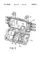
- FIG. 1is an isometric view of an aerial mounted housing within which optical signals translated into electrical signals for television usage;
- FIG. 2is an isometric view of the housing of FIG. 1 and in an open condition
- FIG. 3is a view similar to FIG. 2 and also showing an optical fiber storage holder opened;
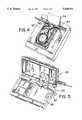
- FIG. 4is an isometric view similar to FIG. 3 but showing only a part of the housing to illustrate the manner in which optical fibers are stored within the holder;
- FIG. 5is a view similar to FIG. 3 to show how the optical fiber storage holder in different orientation
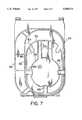
- FIG. 6is a plan view of a base of the holder
- FIG. 7is a plan view of the inside of the lid of the holder.
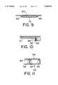
- FIG. 8is a view similar to FIG. 6 and showing relative positions of ribs on the lid to walls of the base of the holder;
- FIGS. 9, 10 and 11are cross-sectional views taken respectively along lines IX--IX, X--X and XI--XI in FIG. 8.
- the systemIn a telecommunications cable system employing optical fibers for transmitting television signals to locations adjacent to buildings, the system is intended to transmit the signals for a short distance between the optical fibers and the television receivers, by use of coaxial electrical cable of known form.
- the signalsare converted from optical to electrical signals within a housing 10 as shown by FIG. 1, the housing 10 being environmentally sealed to prevent moisture and dust ingress.
- the closed container 10is mounted by two brackets 12 to an aerial carrying strand 14 between poles 16 (only one of which is shown).
- a suitable ground wire 18is provided.
- the housing 10comprises two housing parts 20 and 22 which are hingedly connected together along an upper edge so that the housing when in a closed condition hangs about the upper edge substantially vertically from the brackets 12.
- the housing part 20is provided at remote ends, with six inlets 24 for cable, three inlets at each end. Five of the inlets 24 may be used as required for electrical power and television signal requirements by the use of coaxial electrical cables 26 as shown by FIGS. 1, 2 and 3.
- the remaining inlet 24carries an optical fiber cable 26.
- optical fibers 28 of the cable 26extend into the housing 10 to pass to a tray shaped fiber storage holder 30. Ends 32 of the fibers are then brought to connectors 34 exteriorly of the holder 30.
- the connectors 34pass signals from the fibers 32 to a printed circuit board arrangement (not shown) which is contained beneath a lid 36 mounted below the holder 30. From the printed circuit board arrangement, electrical television signals corresponding to the optical signals within the optical fibers 32 are conveyed to one or other of power units 38 carried by the housing part 20 from connectors 40 by electrical cables (not shown).
- the storage holder 30comprises a base and a lid which are pivoted together about one end upon a mounting bracket 42 (see FIG. 5) which is in turn secured within the housing part 22. As shown by FIG. 5 the bracket 42 enables pivotal movement of the storage holder 30 between its operational position on top of the cover 36 in FIG. 2 and a position removed from that position so as to enable the cover 36 to be removed for access to the printed circuit board arrangement.
- the housing 10 in hanging from the strand 14may be subject to any weather conditions which are prevailing.
- the housingmay be subjected to widely differing temperatures and also to wind forces which will have the effect of moving the housing 10 and its contents about the carrying strand 14 which itself will also be movable between the poles 16.
- the storage holder 30may suffer temperature variations and will certainly change in angular orientation to the vertical in an extremely haphazard fashion.
- the optical fibers 28 in passing through the holder 30are caused to move within and possibly out of their storage areas unless positive steps are taken to ensure that this cannot happen.
- the structure of the holder 30 to ensure that the fiber is retained correctly in positionwill now be described.
- the storage holder 30comprises a base 50 with side walls 52 and a lid 54.
- the lidis pivotally mounted to the base about a hinge position coaxial with the hinge for the mounting bracket 42.
- the baseis provided with a plurality of walls 56 which are arcuate and define the outside limits of a storage area 58 for storing windings of optical fiber 60 (see FIG. 4) which are wound around a central substantially circular wall 60.
- the wall 60is disposed at a radius corresponding to the minimum bend radius of the windings of the fiber, at which radius it is believed that no attenuation or physical damage can result to the fiber.
- Other walls 62(FIG.
- the optical cable 26is secured at its end to the associated inlet 24 and optical fibers 28 (only one of which is shown in FIGS. 2 and 4) extend through the container 10 to enter into the holder 30. These fibers then pass into the storage chamber 58 while passing around the internal wall 60 and then to the outlet 64 before being connected to the two optical connectors 34.
- the base and the lidare provided with means for ensuring that the windings remain within the storage chamber with the holder closed and also remain within the storage chamber with the holder open until manually removed therefrom.
- This meanscomprises spaced winding and retaining means of the base in the form of a plurality (namely two) parallel cantilever retaining fingers 70 extending part-way across the widest portion of the storage chamber from the inside wall 60.
- the winding retaining means for the storage chamberalso comprises a plurality (namely five) cantilever retaining fingers 72 which extend radially inwardly of the chamber from chamber boundary walls 56.
- One of the boundary walls 56is spaced from an edge wall 52 to define a splicing region 74 within the base.
- Two further cantilever retaining fingers 76extending outwardly from a wall of the base outwardly of ends of the splicing region.
- This structure of the holder 30 as so far describedis comparable to structures previously used for holding fibers with the holders in permanently horizontal positions. With such holders it has been found that with a base having storage chamber defining walls such as the walls 56 and also incorporating cantilever retaining fingers such as the fingers 70, 72 and 76, that optical fibers have remained in position until manually removed.
- a basehaving storage chamber defining walls such as the walls 56 and also incorporating cantilever retaining fingers such as the fingers 70, 72 and 76, that optical fibers have remained in position until manually removed.
- there is a permanent problemin that with the movement of the container 10 and the subjection of the holder 30 to temperature changes that the stored fibers tend to move from beneath the retaining fingers whereby, when the lid opened upon the holder, the fibers tend to fall out in uncontrollable fashion and are difficult to store once again within the holder.
- the liditself is provided with part of the means for retaining the windings of fiber within the holder particularly when the holder is in the open position.
- the lidis provided with a plurality of ribs which briefly, are positioned to extend alongside and around the fingers 70, 72 and 76 and also to lie closely adjacent to the walls 52, 56 and 62.
- a substantially continuous rib 80is disposed so as to lie completely around the inner wall 60 so as to be directed downwardly into the storage chamber 58.
- This rib 80is provided with two pairs of radially outwardly extending ribs 82.
- the ribs 82 of each pairare disposed closely adjacent to and lie alongside an associated rib 70 (see FIG. 8).
- the ribs 82extend outwards to a further rib 84 which lies closely adjacent to a base wall 56.
- each of the ribs 82depend one down on each side of a finger 70.
- the rib 84 to which the ribs 82 extendis provided integrally with two U-shaped rib formations comprising two parallel rib sides 85 and a base rib 86, the U-shaped rib formation extending completely around and lying closely adjacent to two of the cantilever fingers 72.
- the fibersmay be easily placed in their wound storage positions within the chamber 58 by following the path illustrated in FIG. 3.
- the fiberis moved laterally through the gap provided between the free end of each finger and an opposing wall within the base.
- the windings of the fiberare then positioned within the chamber 58 and also within the passages of the base and are generally located in position by the retaining fingers.
- the various ribs of the lideither lie alongside the top regions of the walls of the base or depend downwardly around the sides and end of the retaining fingers as shown in FIGS. 9, 10 and 11.
Landscapes
- Physics & Mathematics (AREA)
- General Physics & Mathematics (AREA)
- Optics & Photonics (AREA)
- Mechanical Coupling Of Light Guides (AREA)
- Light Guides In General And Applications Therefor (AREA)
Abstract
Description
Claims (9)
Priority Applications (2)
| Application Number | Priority Date | Filing Date | Title |
|---|---|---|---|
| US08/680,285US5668911A (en) | 1996-07-11 | 1996-07-11 | Storage holders for optical fibers |
| CA002202223ACA2202223C (en) | 1996-07-11 | 1997-04-09 | Storage holders for optical fibers |
Applications Claiming Priority (1)
| Application Number | Priority Date | Filing Date | Title |
|---|---|---|---|
| US08/680,285US5668911A (en) | 1996-07-11 | 1996-07-11 | Storage holders for optical fibers |
Publications (1)
| Publication Number | Publication Date |
|---|---|
| US5668911Atrue US5668911A (en) | 1997-09-16 |
Family
ID=24730479
Family Applications (1)
| Application Number | Title | Priority Date | Filing Date |
|---|---|---|---|
| US08/680,285Expired - LifetimeUS5668911A (en) | 1996-07-11 | 1996-07-11 | Storage holders for optical fibers |
Country Status (2)
| Country | Link |
|---|---|
| US (1) | US5668911A (en) |
| CA (1) | CA2202223C (en) |
Cited By (84)
| Publication number | Priority date | Publication date | Assignee | Title |
|---|---|---|---|---|
| DE29722349U1 (en)* | 1997-12-18 | 1998-03-26 | Rehau Ag + Co, 95111 Rehau | Housing for optical components |
| US5781686A (en)* | 1996-02-23 | 1998-07-14 | Leviton Manufacturing Co., Inc. | Multi-media connection housing |
| US5787219A (en)* | 1996-03-20 | 1998-07-28 | Siemens Aktiengesellschaft | Cable closure |
| US5915061A (en)* | 1996-04-05 | 1999-06-22 | Pirelli Cavi S.P.A. | Apparatus and method for housing optical components |
| US5917984A (en)* | 1996-03-14 | 1999-06-29 | Krone Aktiengesellschaft | Management-capable splice cassette |
| US5987207A (en)* | 1997-06-27 | 1999-11-16 | Siecor Corporation | Fiber organizer |
| US6269212B1 (en)* | 1997-09-18 | 2001-07-31 | Pirelli Cavi E Sistemi S.P.A. | Method for performing fixing inside a container for optical connection components |
| GB2367379A (en)* | 2000-09-27 | 2002-04-03 | Krone Gmbh | Fibre optic organiser mounted to a wall |
| US6546180B1 (en)* | 1999-01-06 | 2003-04-08 | Sumitomo Electric Industries, Ltd. | Coiled optical assembly and fabricating method for the same |
| EP1333303A1 (en)* | 2002-01-31 | 2003-08-06 | Moeller Gebäudeautomation KG | Splice cassette system |
| US6650821B1 (en)* | 1999-01-06 | 2003-11-18 | Sumitomo Electric Industries, Ltd. | Optical device and a making method thereof |
| US6661961B1 (en)* | 2000-11-01 | 2003-12-09 | Tyco Electronics Corporation | Fiber low profile network interface device |
| US20040062508A1 (en)* | 2002-09-27 | 2004-04-01 | Blankenship Aaron I. | Fiber optic network interface device |
| US20040175090A1 (en)* | 2001-04-02 | 2004-09-09 | Kristof Vastmans | Optical fibre organiser |
| US20050145522A1 (en)* | 2003-12-24 | 2005-07-07 | Bloodworth Stephen G. | Fiber optic drop cable slack storage receptacle |
| US20050254767A1 (en)* | 2004-05-11 | 2005-11-17 | Chun Hong G | Clips for holding fiber optic cables of a security fence |
| EP1626300A1 (en)* | 2004-08-12 | 2006-02-15 | Genexis B.V. | Housing for optical network interface device |
| US20060153362A1 (en)* | 2005-01-13 | 2006-07-13 | Bloodworth Stephen G | Network interface device for fiber optic communications network |
| WO2008112179A1 (en)* | 2007-03-12 | 2008-09-18 | Corning Cable Systems Llc | Fiber optic local convergence points for multiple dwelling units |
| WO2008149017A1 (en)* | 2007-05-14 | 2008-12-11 | Free | Optical fibre protection hood |
| US20090238531A1 (en)* | 2008-01-09 | 2009-09-24 | Adc Telecommunications, Inc. | Wall box adapted to be mounted at a mid-span access location of a telecommunications cable |
| US20090304342A1 (en)* | 2008-06-09 | 2009-12-10 | Adc Gmbh | Terminal box for fiberoptic cables and panel |
| DE102009008068A1 (en)* | 2009-02-09 | 2010-08-19 | Kathrein-Werke Kg | Network termination enclosure for optical network termination |
| US20110019967A1 (en)* | 2008-04-02 | 2011-01-27 | Adc Gmbh | Cable housing and method for receiving optical fibers and fibers of a fiber optic cable |
| US20110211798A1 (en)* | 2010-02-26 | 2011-09-01 | Connection Technology Systems Inc. | Optical fiber communication conversion device and installing method thereof |
| US8020813B1 (en)* | 2009-07-24 | 2011-09-20 | Cisco Technology, Inc. | Apparatus for routing cable across housing |
| US20110268408A1 (en)* | 2010-04-30 | 2011-11-03 | Giraud William J | Door fiber management for fiber optic housings, and related components and methods |
| AU2011101278B4 (en)* | 2007-03-12 | 2012-02-23 | Corning Cable Systems Llc | Improved optical splitter module |
| US8385711B2 (en) | 2010-04-30 | 2013-02-26 | Corning Cable Systems Llc | Multi-configurable splice holder |
| US8538226B2 (en) | 2009-05-21 | 2013-09-17 | Corning Cable Systems Llc | Fiber optic equipment guides and rails configured with stopping position(s), and related equipment and methods |
| US8542973B2 (en) | 2010-04-23 | 2013-09-24 | Ccs Technology, Inc. | Fiber optic distribution device |
| US8593828B2 (en) | 2010-02-04 | 2013-11-26 | Corning Cable Systems Llc | Communications equipment housings, assemblies, and related alignment features and methods |
| US8625950B2 (en) | 2009-12-18 | 2014-01-07 | Corning Cable Systems Llc | Rotary locking apparatus for fiber optic equipment trays and related methods |
| US8660397B2 (en) | 2010-04-30 | 2014-02-25 | Corning Cable Systems Llc | Multi-layer module |
| US8662760B2 (en) | 2010-10-29 | 2014-03-04 | Corning Cable Systems Llc | Fiber optic connector employing optical fiber guide member |
| US20140101709A1 (en)* | 2012-10-05 | 2014-04-10 | General Instrument Corporation | Optical Fiber Management Bridge |
| US8699838B2 (en) | 2009-05-14 | 2014-04-15 | Ccs Technology, Inc. | Fiber optic furcation module |
| US8705926B2 (en) | 2010-04-30 | 2014-04-22 | Corning Optical Communications LLC | Fiber optic housings having a removable top, and related components and methods |
| US8712206B2 (en) | 2009-06-19 | 2014-04-29 | Corning Cable Systems Llc | High-density fiber optic modules and module housings and related equipment |
| US8718436B2 (en) | 2010-08-30 | 2014-05-06 | Corning Cable Systems Llc | Methods, apparatuses for providing secure fiber optic connections |
| US8879881B2 (en) | 2010-04-30 | 2014-11-04 | Corning Cable Systems Llc | Rotatable routing guide and assembly |
| US8913866B2 (en) | 2010-03-26 | 2014-12-16 | Corning Cable Systems Llc | Movable adapter panel |
| US8953924B2 (en) | 2011-09-02 | 2015-02-10 | Corning Cable Systems Llc | Removable strain relief brackets for securing fiber optic cables and/or optical fibers to fiber optic equipment, and related assemblies and methods |
| US8965168B2 (en) | 2010-04-30 | 2015-02-24 | Corning Cable Systems Llc | Fiber management devices for fiber optic housings, and related components and methods |
| US8985862B2 (en) | 2013-02-28 | 2015-03-24 | Corning Cable Systems Llc | High-density multi-fiber adapter housings |
| US8989547B2 (en) | 2011-06-30 | 2015-03-24 | Corning Cable Systems Llc | Fiber optic equipment assemblies employing non-U-width-sized housings and related methods |
| US8995812B2 (en) | 2012-10-26 | 2015-03-31 | Ccs Technology, Inc. | Fiber optic management unit and fiber optic distribution device |
| US9008485B2 (en) | 2011-05-09 | 2015-04-14 | Corning Cable Systems Llc | Attachment mechanisms employed to attach a rear housing section to a fiber optic housing, and related assemblies and methods |
| US9020320B2 (en) | 2008-08-29 | 2015-04-28 | Corning Cable Systems Llc | High density and bandwidth fiber optic apparatuses and related equipment and methods |
| US9022814B2 (en) | 2010-04-16 | 2015-05-05 | Ccs Technology, Inc. | Sealing and strain relief device for data cables |
| US9042702B2 (en) | 2012-09-18 | 2015-05-26 | Corning Cable Systems Llc | Platforms and systems for fiber optic cable attachment |
| US9038832B2 (en) | 2011-11-30 | 2015-05-26 | Corning Cable Systems Llc | Adapter panel support assembly |
| US9059578B2 (en) | 2009-02-24 | 2015-06-16 | Ccs Technology, Inc. | Holding device for a cable or an assembly for use with a cable |
| US9075217B2 (en) | 2010-04-30 | 2015-07-07 | Corning Cable Systems Llc | Apparatuses and related components and methods for expanding capacity of fiber optic housings |
| US9116324B2 (en) | 2010-10-29 | 2015-08-25 | Corning Cable Systems Llc | Stacked fiber optic modules and fiber optic equipment configured to support stacked fiber optic modules |
| CN104965273A (en)* | 2015-06-30 | 2015-10-07 | 许继集团有限公司 | Fiber adapter box body, fiber adapter box, and prefabricated cabin front-wiring screen cabinet |
| US9213161B2 (en) | 2010-11-05 | 2015-12-15 | Corning Cable Systems Llc | Fiber body holder and strain relief device |
| US9250409B2 (en) | 2012-07-02 | 2016-02-02 | Corning Cable Systems Llc | Fiber-optic-module trays and drawers for fiber-optic equipment |
| US20160033056A1 (en)* | 2014-07-31 | 2016-02-04 | Tyco Electronics Corporation | Enclosure hanger assembly and cable management system |
| US9279951B2 (en) | 2010-10-27 | 2016-03-08 | Corning Cable Systems Llc | Fiber optic module for limited space applications having a partially sealed module sub-assembly |
| US20160091681A1 (en)* | 2014-09-23 | 2016-03-31 | Ppc Broadband, Inc. | Universal multi-purpose compartmentalized telecommunications box |
| WO2016050815A1 (en)* | 2014-09-30 | 2016-04-07 | Tyco Electronics Raychem Bvba | System and method of fiber distribution |
| US9519118B2 (en) | 2010-04-30 | 2016-12-13 | Corning Optical Communications LLC | Removable fiber management sections for fiber optic housings, and related components and methods |
| CN102884466B (en)* | 2010-05-07 | 2016-12-14 | 康宁光缆系统有限责任公司 | Door fiber management for fiber optic housings, and related assemblies and methods |
| WO2017001582A3 (en)* | 2015-06-30 | 2017-02-09 | CommScope Connectivity Belgium BVBA | System for compensation of expansion/contraction of a cooling medium inside a sealed closure |
| US9612416B2 (en)* | 2014-12-31 | 2017-04-04 | All Systems Broadband, Inc. | Fiber demarcation box for layering and storing coiled fiber optic cabling |
| US9632270B2 (en) | 2010-04-30 | 2017-04-25 | Corning Optical Communications LLC | Fiber optic housings configured for tool-less assembly, and related components and methods |
| US9645317B2 (en) | 2011-02-02 | 2017-05-09 | Corning Optical Communications LLC | Optical backplane extension modules, and related assemblies suitable for establishing optical connections to information processing modules disposed in equipment racks |
| US9720195B2 (en) | 2010-04-30 | 2017-08-01 | Corning Optical Communications LLC | Apparatuses and related components and methods for attachment and release of fiber optic housings to and from an equipment rack |
| EP2156228B1 (en)* | 2007-06-07 | 2017-08-09 | Free | Junction box for optical fibres |
| USRE46525E1 (en) | 2007-01-12 | 2017-08-29 | Corning Optical Communications LLC | Fiber optic local convergence points for multiple dwelling units |
| US9835814B2 (en)* | 2013-11-06 | 2017-12-05 | Adc Czech Republic S.R.O. | Fiber termination point with overlength storage |
| EP2561389A4 (en)* | 2010-04-23 | 2017-12-13 | CCS Technology, Inc. | Removable fiber optic splice tray |
| US9882362B2 (en)* | 2014-09-23 | 2018-01-30 | Ppc Broadband, Inc. | Enclosure for controling access to different telecommunication components |
| US9939602B2 (en) | 2014-12-09 | 2018-04-10 | Commscope Technologies Llc | Mounting system and kit for aerial mounting of a fiber optic enclosure |
| US10094996B2 (en) | 2008-08-29 | 2018-10-09 | Corning Optical Communications, Llc | Independently translatable modules and fiber optic equipment trays in fiber optic equipment |
| US10509187B2 (en) | 2014-09-23 | 2019-12-17 | Ppc Broadband, Inc. | Universal multi-purpose compartmentalized telecommunications box |
| US10976512B2 (en) | 2014-09-23 | 2021-04-13 | Ppc Broadband, Inc. | House box with mounting surface for mounted access |
| US20210373270A1 (en)* | 2018-09-07 | 2021-12-02 | Go!Foton Holdings, Inc. | Optical Fiber Distribution System |
| US11294136B2 (en) | 2008-08-29 | 2022-04-05 | Corning Optical Communications LLC | High density and bandwidth fiber optic apparatuses and related equipment and methods |
| US20230026759A1 (en)* | 2018-04-23 | 2023-01-26 | Commscope Technologies Llc | Mounting bracket system for telecommunications equipment |
| US20230164367A1 (en)* | 2021-11-23 | 2023-05-25 | Applied Optoelectronics, Inc. | Node housing with lid-based mounting of node components for use in a broadband distribution network |
| US12222573B2 (en) | 2020-08-07 | 2025-02-11 | Commscope Technologies Llc | Adjustable cable management system |
| US12235503B2 (en) | 2019-11-07 | 2025-02-25 | Commscope Technologies Llc | Telecommunications enclosure mounting system |
Citations (3)
| Publication number | Priority date | Publication date | Assignee | Title |
|---|---|---|---|---|
| US5067784A (en)* | 1990-11-19 | 1991-11-26 | George Debortoli | Connector holders |
| US5337400A (en)* | 1992-10-28 | 1994-08-09 | Northern Telecom Limited | Distribution frame and optical connector holder combination |
| US5353367A (en)* | 1993-11-29 | 1994-10-04 | Northern Telecom Limited | Distribution frame and optical connector holder combination |
- 1996
- 1996-07-11USUS08/680,285patent/US5668911A/ennot_activeExpired - Lifetime
- 1997
- 1997-04-09CACA002202223Apatent/CA2202223C/ennot_activeExpired - Fee Related
Patent Citations (3)
| Publication number | Priority date | Publication date | Assignee | Title |
|---|---|---|---|---|
| US5067784A (en)* | 1990-11-19 | 1991-11-26 | George Debortoli | Connector holders |
| US5337400A (en)* | 1992-10-28 | 1994-08-09 | Northern Telecom Limited | Distribution frame and optical connector holder combination |
| US5353367A (en)* | 1993-11-29 | 1994-10-04 | Northern Telecom Limited | Distribution frame and optical connector holder combination |
Cited By (147)
| Publication number | Priority date | Publication date | Assignee | Title |
|---|---|---|---|---|
| US5781686A (en)* | 1996-02-23 | 1998-07-14 | Leviton Manufacturing Co., Inc. | Multi-media connection housing |
| US5917984A (en)* | 1996-03-14 | 1999-06-29 | Krone Aktiengesellschaft | Management-capable splice cassette |
| US5787219A (en)* | 1996-03-20 | 1998-07-28 | Siemens Aktiengesellschaft | Cable closure |
| US5915061A (en)* | 1996-04-05 | 1999-06-22 | Pirelli Cavi S.P.A. | Apparatus and method for housing optical components |
| AU716127B2 (en)* | 1996-04-05 | 2000-02-17 | Corning O.T.I Inc. | Apparatus and method for housing optical components |
| US5987207A (en)* | 1997-06-27 | 1999-11-16 | Siecor Corporation | Fiber organizer |
| US6269212B1 (en)* | 1997-09-18 | 2001-07-31 | Pirelli Cavi E Sistemi S.P.A. | Method for performing fixing inside a container for optical connection components |
| DE29722349U1 (en)* | 1997-12-18 | 1998-03-26 | Rehau Ag + Co, 95111 Rehau | Housing for optical components |
| US6650821B1 (en)* | 1999-01-06 | 2003-11-18 | Sumitomo Electric Industries, Ltd. | Optical device and a making method thereof |
| US7043131B2 (en) | 1999-01-06 | 2006-05-09 | Sumitomo Electric Industries, Ltd. | Optical device and a making method thereof |
| US6546180B1 (en)* | 1999-01-06 | 2003-04-08 | Sumitomo Electric Industries, Ltd. | Coiled optical assembly and fabricating method for the same |
| US20030142938A1 (en)* | 1999-01-06 | 2003-07-31 | Sumitomo Electric Industries, Ltd. | Coiled optical assembly and fabricating method for the same |
| GB2367379B (en)* | 2000-09-27 | 2004-08-25 | Krone Gmbh | Opitcal fibre connection housing |
| WO2002027883A3 (en)* | 2000-09-27 | 2003-05-15 | Krone Gmbh | Optical fiber connection housing |
| GB2367379A (en)* | 2000-09-27 | 2002-04-03 | Krone Gmbh | Fibre optic organiser mounted to a wall |
| US20040013389A1 (en)* | 2000-09-27 | 2004-01-22 | Taylor Christopher Charles | Optical fiber connection housing |
| KR100816317B1 (en)* | 2000-09-27 | 2008-03-24 | 에이디씨 게엠베하 | Fiber optic connection housing |
| US6788871B2 (en) | 2000-09-27 | 2004-09-07 | Krone Gmbh | Optical fiber connection housing with an outlet connector element and a splice connection to an optical line group |
| CN1327257C (en)* | 2000-09-27 | 2007-07-18 | Adc有限责任公司 | Optical fiber connection housing |
| US6661961B1 (en)* | 2000-11-01 | 2003-12-09 | Tyco Electronics Corporation | Fiber low profile network interface device |
| US20040175090A1 (en)* | 2001-04-02 | 2004-09-09 | Kristof Vastmans | Optical fibre organiser |
| EP1333303A1 (en)* | 2002-01-31 | 2003-08-06 | Moeller Gebäudeautomation KG | Splice cassette system |
| US6721484B1 (en)* | 2002-09-27 | 2004-04-13 | Corning Cable Systems Llc | Fiber optic network interface device |
| US20040062508A1 (en)* | 2002-09-27 | 2004-04-01 | Blankenship Aaron I. | Fiber optic network interface device |
| US20050145522A1 (en)* | 2003-12-24 | 2005-07-07 | Bloodworth Stephen G. | Fiber optic drop cable slack storage receptacle |
| US7346253B2 (en) | 2003-12-24 | 2008-03-18 | Corning Cable Systems Llc | Fiber optic drop cable slack storage receptacle |
| US20050254767A1 (en)* | 2004-05-11 | 2005-11-17 | Chun Hong G | Clips for holding fiber optic cables of a security fence |
| US7177518B2 (en)* | 2004-05-11 | 2007-02-13 | Fomguard Inc. | Clips for holding fiber optic cables of a security fence |
| EP1626300A1 (en)* | 2004-08-12 | 2006-02-15 | Genexis B.V. | Housing for optical network interface device |
| US20060153362A1 (en)* | 2005-01-13 | 2006-07-13 | Bloodworth Stephen G | Network interface device for fiber optic communications network |
| USRE46701E1 (en) | 2007-01-12 | 2018-02-06 | Corning Cable Systems Llc | Fiber optic local convergence points for multiple dwelling units |
| USRE48082E1 (en) | 2007-01-12 | 2020-07-07 | Corning Optical Communications LLP | Fiber optic local convergence points for multiple dwelling units |
| USRE50042E1 (en) | 2007-01-12 | 2024-07-16 | Corning Optical Communications LLC | Fiber optic local convergence points for multiple dwelling units |
| USRE48937E1 (en) | 2007-01-12 | 2022-02-22 | Corning Optical Communications LLC | Fiber optic local convergence points for multiple dwelling units |
| USRE46525E1 (en) | 2007-01-12 | 2017-08-29 | Corning Optical Communications LLC | Fiber optic local convergence points for multiple dwelling units |
| WO2008112179A1 (en)* | 2007-03-12 | 2008-09-18 | Corning Cable Systems Llc | Fiber optic local convergence points for multiple dwelling units |
| AU2011101278B4 (en)* | 2007-03-12 | 2012-02-23 | Corning Cable Systems Llc | Improved optical splitter module |
| WO2008149017A1 (en)* | 2007-05-14 | 2008-12-11 | Free | Optical fibre protection hood |
| EP2156228B1 (en)* | 2007-06-07 | 2017-08-09 | Free | Junction box for optical fibres |
| US8837894B2 (en) | 2008-01-09 | 2014-09-16 | Adc Telecommunications, Inc. | Wall box adapted to be mounted at a mid-span access location of a telecommunications cable |
| US10422970B2 (en) | 2008-01-09 | 2019-09-24 | Commscope Technologies Llc | Wall box adapted to be mounted at a mid-span access location of a telecommunications cable |
| US8111966B2 (en)* | 2008-01-09 | 2012-02-07 | Adc Telecommunications, Inc. | Wall box adapted to be mounted at a mid-span access location of a telecommunications cable |
| US9557504B2 (en) | 2008-01-09 | 2017-01-31 | Commscope Technologies Llc | Wall box adapted to be mounted at a mid-span access location of a telecommunications cable |
| US11592636B2 (en) | 2008-01-09 | 2023-02-28 | Commscope Technologies Llc | Wall box adapted to be mounted at a mid-span access location of a telecommunications cable |
| US20090238531A1 (en)* | 2008-01-09 | 2009-09-24 | Adc Telecommunications, Inc. | Wall box adapted to be mounted at a mid-span access location of a telecommunications cable |
| US11036018B2 (en)* | 2008-01-09 | 2021-06-15 | Commscope Technologies Llc | Wall box adapted to be mounted at a mid-span access location of a telecommunications cable |
| US8606068B2 (en)* | 2008-04-02 | 2013-12-10 | Adc Gmbh | Cable housing and method for receiving optical fibers and fibers of a fiber optic cable |
| US20110019967A1 (en)* | 2008-04-02 | 2011-01-27 | Adc Gmbh | Cable housing and method for receiving optical fibers and fibers of a fiber optic cable |
| US8509586B2 (en) | 2008-06-09 | 2013-08-13 | Adc Gmbh | Terminal box for fiberoptic cables and panel |
| US20090304342A1 (en)* | 2008-06-09 | 2009-12-10 | Adc Gmbh | Terminal box for fiberoptic cables and panel |
| WO2009149814A1 (en) | 2008-06-09 | 2009-12-17 | Adc Gmbh | Termination box for glass fiber cables, and panel |
| US10422971B2 (en) | 2008-08-29 | 2019-09-24 | Corning Optical Communicatinos LLC | High density and bandwidth fiber optic apparatuses and related equipment and methods |
| US10416405B2 (en) | 2008-08-29 | 2019-09-17 | Corning Optical Communications LLC | Independently translatable modules and fiber optic equipment trays in fiber optic equipment |
| US11294135B2 (en) | 2008-08-29 | 2022-04-05 | Corning Optical Communications LLC | High density and bandwidth fiber optic apparatuses and related equipment and methods |
| US10606014B2 (en) | 2008-08-29 | 2020-03-31 | Corning Optical Communications LLC | Independently translatable modules and fiber optic equipment trays in fiber optic equipment |
| US10564378B2 (en) | 2008-08-29 | 2020-02-18 | Corning Optical Communications LLC | High density and bandwidth fiber optic apparatuses and related equipment and methods |
| US10459184B2 (en) | 2008-08-29 | 2019-10-29 | Corning Optical Communications LLC | High density and bandwidth fiber optic apparatuses and related equipment and methods |
| US10444456B2 (en) | 2008-08-29 | 2019-10-15 | Corning Optical Communications LLC | High density and bandwidth fiber optic apparatuses and related equipment and methods |
| US11609396B2 (en) | 2008-08-29 | 2023-03-21 | Corning Optical Communications LLC | High density and bandwidth fiber optic apparatuses and related equipment and methods |
| US9020320B2 (en) | 2008-08-29 | 2015-04-28 | Corning Cable Systems Llc | High density and bandwidth fiber optic apparatuses and related equipment and methods |
| US10852499B2 (en) | 2008-08-29 | 2020-12-01 | Corning Optical Communications LLC | High density and bandwidth fiber optic apparatuses and related equipment and methods |
| US11754796B2 (en) | 2008-08-29 | 2023-09-12 | Corning Optical Communications LLC | Independently translatable modules and fiber optic equipment trays in fiber optic equipment |
| US10222570B2 (en) | 2008-08-29 | 2019-03-05 | Corning Optical Communications LLC | Independently translatable modules and fiber optic equipment trays in fiber optic equipment |
| US10126514B2 (en) | 2008-08-29 | 2018-11-13 | Corning Optical Communications, Llc | Independently translatable modules and fiber optic equipment trays in fiber optic equipment |
| US10120153B2 (en) | 2008-08-29 | 2018-11-06 | Corning Optical Communications, Llc | Independently translatable modules and fiber optic equipment trays in fiber optic equipment |
| US10094996B2 (en) | 2008-08-29 | 2018-10-09 | Corning Optical Communications, Llc | Independently translatable modules and fiber optic equipment trays in fiber optic equipment |
| US9910236B2 (en) | 2008-08-29 | 2018-03-06 | Corning Optical Communications LLC | High density and bandwidth fiber optic apparatuses and related equipment and methods |
| US12072545B2 (en) | 2008-08-29 | 2024-08-27 | Corning Optical Communications LLC | High density and bandwidth fiber optic apparatuses and related equipment and methods |
| US11294136B2 (en) | 2008-08-29 | 2022-04-05 | Corning Optical Communications LLC | High density and bandwidth fiber optic apparatuses and related equipment and methods |
| US11086089B2 (en) | 2008-08-29 | 2021-08-10 | Corning Optical Communications LLC | High density and bandwidth fiber optic apparatuses and related equipment and methods |
| US11092767B2 (en) | 2008-08-29 | 2021-08-17 | Corning Optical Communications LLC | High density and bandwidth fiber optic apparatuses and related equipment and methods |
| DE102009008068A1 (en)* | 2009-02-09 | 2010-08-19 | Kathrein-Werke Kg | Network termination enclosure for optical network termination |
| DE102009008068B4 (en)* | 2009-02-09 | 2014-03-27 | Kathrein-Werke Kg | Network termination enclosure for optical network termination |
| US9059578B2 (en) | 2009-02-24 | 2015-06-16 | Ccs Technology, Inc. | Holding device for a cable or an assembly for use with a cable |
| US8699838B2 (en) | 2009-05-14 | 2014-04-15 | Ccs Technology, Inc. | Fiber optic furcation module |
| US8538226B2 (en) | 2009-05-21 | 2013-09-17 | Corning Cable Systems Llc | Fiber optic equipment guides and rails configured with stopping position(s), and related equipment and methods |
| US9075216B2 (en) | 2009-05-21 | 2015-07-07 | Corning Cable Systems Llc | Fiber optic housings configured to accommodate fiber optic modules/cassettes and fiber optic panels, and related components and methods |
| US8712206B2 (en) | 2009-06-19 | 2014-04-29 | Corning Cable Systems Llc | High-density fiber optic modules and module housings and related equipment |
| US8020813B1 (en)* | 2009-07-24 | 2011-09-20 | Cisco Technology, Inc. | Apparatus for routing cable across housing |
| US8625950B2 (en) | 2009-12-18 | 2014-01-07 | Corning Cable Systems Llc | Rotary locking apparatus for fiber optic equipment trays and related methods |
| US8593828B2 (en) | 2010-02-04 | 2013-11-26 | Corning Cable Systems Llc | Communications equipment housings, assemblies, and related alignment features and methods |
| US8992099B2 (en) | 2010-02-04 | 2015-03-31 | Corning Cable Systems Llc | Optical interface cards, assemblies, and related methods, suited for installation and use in antenna system equipment |
| TWI408431B (en)* | 2010-02-26 | 2013-09-11 | Connection Technology Systems Inc | Fiber communication conversion device and the installing method therefor |
| US20110211798A1 (en)* | 2010-02-26 | 2011-09-01 | Connection Technology Systems Inc. | Optical fiber communication conversion device and installing method thereof |
| US8355616B2 (en)* | 2010-02-26 | 2013-01-15 | Connection Technology Systems Inc. | Optical fiber communication conversion device and installing method thereof |
| US8913866B2 (en) | 2010-03-26 | 2014-12-16 | Corning Cable Systems Llc | Movable adapter panel |
| US9022814B2 (en) | 2010-04-16 | 2015-05-05 | Ccs Technology, Inc. | Sealing and strain relief device for data cables |
| US8542973B2 (en) | 2010-04-23 | 2013-09-24 | Ccs Technology, Inc. | Fiber optic distribution device |
| EP2561389A4 (en)* | 2010-04-23 | 2017-12-13 | CCS Technology, Inc. | Removable fiber optic splice tray |
| US8965168B2 (en) | 2010-04-30 | 2015-02-24 | Corning Cable Systems Llc | Fiber management devices for fiber optic housings, and related components and methods |
| US8705926B2 (en) | 2010-04-30 | 2014-04-22 | Corning Optical Communications LLC | Fiber optic housings having a removable top, and related components and methods |
| US8660397B2 (en) | 2010-04-30 | 2014-02-25 | Corning Cable Systems Llc | Multi-layer module |
| US8879881B2 (en) | 2010-04-30 | 2014-11-04 | Corning Cable Systems Llc | Rotatable routing guide and assembly |
| US9632270B2 (en) | 2010-04-30 | 2017-04-25 | Corning Optical Communications LLC | Fiber optic housings configured for tool-less assembly, and related components and methods |
| US8385711B2 (en) | 2010-04-30 | 2013-02-26 | Corning Cable Systems Llc | Multi-configurable splice holder |
| US9720195B2 (en) | 2010-04-30 | 2017-08-01 | Corning Optical Communications LLC | Apparatuses and related components and methods for attachment and release of fiber optic housings to and from an equipment rack |
| US20110268408A1 (en)* | 2010-04-30 | 2011-11-03 | Giraud William J | Door fiber management for fiber optic housings, and related components and methods |
| US9519118B2 (en) | 2010-04-30 | 2016-12-13 | Corning Optical Communications LLC | Removable fiber management sections for fiber optic housings, and related components and methods |
| US9075217B2 (en) | 2010-04-30 | 2015-07-07 | Corning Cable Systems Llc | Apparatuses and related components and methods for expanding capacity of fiber optic housings |
| CN102884466B (en)* | 2010-05-07 | 2016-12-14 | 康宁光缆系统有限责任公司 | Door fiber management for fiber optic housings, and related assemblies and methods |
| WO2011140540A1 (en)* | 2010-05-07 | 2011-11-10 | Corning Cable Systems Llc | Door fiber management for fiber optic housings, and related components and methods |
| CN102884466A (en)* | 2010-05-07 | 2013-01-16 | 康宁光缆系统有限责任公司 | Door fiber management for fiber optic housings, and related assemblies and methods |
| US8718436B2 (en) | 2010-08-30 | 2014-05-06 | Corning Cable Systems Llc | Methods, apparatuses for providing secure fiber optic connections |
| US9279951B2 (en) | 2010-10-27 | 2016-03-08 | Corning Cable Systems Llc | Fiber optic module for limited space applications having a partially sealed module sub-assembly |
| US9116324B2 (en) | 2010-10-29 | 2015-08-25 | Corning Cable Systems Llc | Stacked fiber optic modules and fiber optic equipment configured to support stacked fiber optic modules |
| US8662760B2 (en) | 2010-10-29 | 2014-03-04 | Corning Cable Systems Llc | Fiber optic connector employing optical fiber guide member |
| US9213161B2 (en) | 2010-11-05 | 2015-12-15 | Corning Cable Systems Llc | Fiber body holder and strain relief device |
| US9645317B2 (en) | 2011-02-02 | 2017-05-09 | Corning Optical Communications LLC | Optical backplane extension modules, and related assemblies suitable for establishing optical connections to information processing modules disposed in equipment racks |
| US10481335B2 (en) | 2011-02-02 | 2019-11-19 | Corning Optical Communications, Llc | Dense shuttered fiber optic connectors and assemblies suitable for establishing optical connections for optical backplanes in equipment racks |
| US9008485B2 (en) | 2011-05-09 | 2015-04-14 | Corning Cable Systems Llc | Attachment mechanisms employed to attach a rear housing section to a fiber optic housing, and related assemblies and methods |
| US8989547B2 (en) | 2011-06-30 | 2015-03-24 | Corning Cable Systems Llc | Fiber optic equipment assemblies employing non-U-width-sized housings and related methods |
| US8953924B2 (en) | 2011-09-02 | 2015-02-10 | Corning Cable Systems Llc | Removable strain relief brackets for securing fiber optic cables and/or optical fibers to fiber optic equipment, and related assemblies and methods |
| US9038832B2 (en) | 2011-11-30 | 2015-05-26 | Corning Cable Systems Llc | Adapter panel support assembly |
| US9250409B2 (en) | 2012-07-02 | 2016-02-02 | Corning Cable Systems Llc | Fiber-optic-module trays and drawers for fiber-optic equipment |
| US9042702B2 (en) | 2012-09-18 | 2015-05-26 | Corning Cable Systems Llc | Platforms and systems for fiber optic cable attachment |
| US9002167B2 (en)* | 2012-10-05 | 2015-04-07 | Google Technology Holdings LLC | Optical fiber management bridge |
| US20140101709A1 (en)* | 2012-10-05 | 2014-04-10 | General Instrument Corporation | Optical Fiber Management Bridge |
| US8995812B2 (en) | 2012-10-26 | 2015-03-31 | Ccs Technology, Inc. | Fiber optic management unit and fiber optic distribution device |
| US8985862B2 (en) | 2013-02-28 | 2015-03-24 | Corning Cable Systems Llc | High-density multi-fiber adapter housings |
| US9835814B2 (en)* | 2013-11-06 | 2017-12-05 | Adc Czech Republic S.R.O. | Fiber termination point with overlength storage |
| US20160033056A1 (en)* | 2014-07-31 | 2016-02-04 | Tyco Electronics Corporation | Enclosure hanger assembly and cable management system |
| US9377132B2 (en)* | 2014-07-31 | 2016-06-28 | Commscope Technologies Llc | Enclosure hanger assembly and cable management system |
| US10509187B2 (en) | 2014-09-23 | 2019-12-17 | Ppc Broadband, Inc. | Universal multi-purpose compartmentalized telecommunications box |
| US10914908B2 (en) | 2014-09-23 | 2021-02-09 | Ppc Broadband, Inc. | Access control device for permitting access to a component while selectively blocking access to another type of component |
| US10976512B2 (en) | 2014-09-23 | 2021-04-13 | Ppc Broadband, Inc. | House box with mounting surface for mounted access |
| US20160091681A1 (en)* | 2014-09-23 | 2016-03-31 | Ppc Broadband, Inc. | Universal multi-purpose compartmentalized telecommunications box |
| US9882362B2 (en)* | 2014-09-23 | 2018-01-30 | Ppc Broadband, Inc. | Enclosure for controling access to different telecommunication components |
| US11719900B2 (en)* | 2014-09-23 | 2023-08-08 | Ppc Broadband, Inc. | Universal multi-purpose compartmentalized telecommunications box |
| US11698500B2 (en) | 2014-09-23 | 2023-07-11 | Ppc Broadband, Inc. | Access control device for permitting access to a component while selectively blocking access to another type of component |
| US9952397B2 (en)* | 2014-09-23 | 2018-04-24 | Ppc Broadband Inc. | Universal multi-purpose compartmentalized telecommunications box |
| US9952396B2 (en)* | 2014-09-30 | 2018-04-24 | CommScope Connectivity Belgium BVBA | System and method of fiber distribution |
| US10509188B2 (en) | 2014-09-30 | 2019-12-17 | CommScope Connectivity Belgium BVBA | System and method of fiber distribution |
| WO2016050815A1 (en)* | 2014-09-30 | 2016-04-07 | Tyco Electronics Raychem Bvba | System and method of fiber distribution |
| US9939602B2 (en) | 2014-12-09 | 2018-04-10 | Commscope Technologies Llc | Mounting system and kit for aerial mounting of a fiber optic enclosure |
| US10768390B2 (en) | 2014-12-09 | 2020-09-08 | Commscope Technologies Llc | Mounting system and kit for aerial mounting of a fiber optic enclosure |
| US9612416B2 (en)* | 2014-12-31 | 2017-04-04 | All Systems Broadband, Inc. | Fiber demarcation box for layering and storing coiled fiber optic cabling |
| WO2017001582A3 (en)* | 2015-06-30 | 2017-02-09 | CommScope Connectivity Belgium BVBA | System for compensation of expansion/contraction of a cooling medium inside a sealed closure |
| CN104965273B (en)* | 2015-06-30 | 2018-09-21 | 许继集团有限公司 | Wiring screen cabinet before optic fibre switching box body, optic fibre switching case and prefabricated cabin |
| CN104965273A (en)* | 2015-06-30 | 2015-10-07 | 许继集团有限公司 | Fiber adapter box body, fiber adapter box, and prefabricated cabin front-wiring screen cabinet |
| US20230026759A1 (en)* | 2018-04-23 | 2023-01-26 | Commscope Technologies Llc | Mounting bracket system for telecommunications equipment |
| US12222568B2 (en)* | 2018-04-23 | 2025-02-11 | Commscope Technologies Llc | Mounting bracket system for telecommunications equipment |
| US20210373270A1 (en)* | 2018-09-07 | 2021-12-02 | Go!Foton Holdings, Inc. | Optical Fiber Distribution System |
| US11630278B2 (en)* | 2018-09-07 | 2023-04-18 | Go!Foton Holdings, Inc. | Optical fiber distribution system |
| US12235503B2 (en) | 2019-11-07 | 2025-02-25 | Commscope Technologies Llc | Telecommunications enclosure mounting system |
| US12222573B2 (en) | 2020-08-07 | 2025-02-11 | Commscope Technologies Llc | Adjustable cable management system |
| US11812072B2 (en)* | 2021-11-23 | 2023-11-07 | Applied Optoelectronics, Inc. | Node housing with lid-based mounting of node components for use in a broadband distribution network |
| US20230164367A1 (en)* | 2021-11-23 | 2023-05-25 | Applied Optoelectronics, Inc. | Node housing with lid-based mounting of node components for use in a broadband distribution network |
Also Published As
| Publication number | Publication date |
|---|---|
| CA2202223C (en) | 2004-06-01 |
| CA2202223A1 (en) | 1998-01-11 |
Similar Documents
| Publication | Publication Date | Title |
|---|---|---|
| US5668911A (en) | Storage holders for optical fibers | |
| EP1579258B1 (en) | Unitary splice and drop wire closure | |
| US5696864A (en) | Aerial enclosure for coupling data signals to a customer site | |
| US4595255A (en) | Optical fiber wiring center | |
| JP4728249B2 (en) | Systems and methods for optical fiber placement and management | |
| EP1929347B1 (en) | Enclosure for telecommunication lines and splices | |
| US7562779B2 (en) | Cable management rack with pass-through tray | |
| EP0531628A1 (en) | Device for dividing optical fibre cables and wires | |
| US9723733B2 (en) | Metro cell aggregator enclosure | |
| WO2006076115A1 (en) | Network interface device having integral slack storage compartment | |
| WO2006076120A1 (en) | Network interface device for fiber optic communications network | |
| WO1991007680A2 (en) | Telecommunication closures | |
| EP1929346A2 (en) | Enclosure and organizer for telecommunication lines and splices | |
| US20240036281A1 (en) | Telecommunications cable termination box | |
| US7848608B2 (en) | Fiber routing system with drop-in device | |
| US5515435A (en) | Network interface device with apertures for holding flexible coaxial cable connector | |
| KR20150078321A (en) | Terminal box for optical fiber and power line composite cable | |
| JPH08507387A (en) | Hermetic fiber optic closure | |
| US20080292249A1 (en) | Electronic equipment | |
| KR100962257B1 (en) | Optical box | |
| KR20020027322A (en) | Handling of optical fibres in confinded or limited spaces | |
| US6330389B1 (en) | System for organizing optical fibers | |
| WO2018203888A1 (en) | Fiber optic connection box with fluid drainage chute for preventing water ingress | |
| US7289625B2 (en) | Portable sealable telecommunications exchange equipment structure | |
| EP1293815A1 (en) | Cover for fiber optic splice cassette |
Legal Events
| Date | Code | Title | Description |
|---|---|---|---|
| AS | Assignment | Owner name:BELL-NORTHERN RESEARCH LTD., CANADA Free format text:ASSIGNMENT OF ASSIGNORS INTEREST;ASSIGNOR:DEBORTOLI, GEORGE;REEL/FRAME:008109/0392 Effective date:19960709 | |
| AS | Assignment | Owner name:NORTHERN TELECOM LIMITED, CANADA Free format text:ASSIGNMENT OF ASSIGNORS INTEREST;ASSIGNOR:BEELL-NORTHERN RESEARCH LTD.;REEL/FRAME:008323/0511 Effective date:19961231 | |
| STCF | Information on status: patent grant | Free format text:PATENTED CASE | |
| AS | Assignment | Owner name:NORTEL NETWORKS CORPORATION, CANADA Free format text:CHANGE OF NAME;ASSIGNOR:NORTHERN TELECOM LIMITED;REEL/FRAME:010567/0001 Effective date:19990429 | |
| AS | Assignment | Owner name:NORTEL NETWORKS LIMITED, CANADA Free format text:CHANGE OF NAME;ASSIGNOR:NORTEL NETWORKS CORPORATION;REEL/FRAME:011195/0706 Effective date:20000830 Owner name:NORTEL NETWORKS LIMITED,CANADA Free format text:CHANGE OF NAME;ASSIGNOR:NORTEL NETWORKS CORPORATION;REEL/FRAME:011195/0706 Effective date:20000830 | |
| FPAY | Fee payment | Year of fee payment:4 | |
| FPAY | Fee payment | Year of fee payment:8 | |
| AS | Assignment | Owner name:INDEPENDENCE MANZANAR LLC, NEVADA Free format text:ASSIGNMENT OF ASSIGNORS INTEREST;ASSIGNOR:NORTEL NETWORKS LIMITED;REEL/FRAME:017286/0465 Effective date:20050406 | |
| FPAY | Fee payment | Year of fee payment:12 | |
| AS | Assignment | Owner name:ZARBANA DIGITAL FUND LLC, DELAWARE Free format text:MERGER;ASSIGNOR:INDEPENDENCE MANZANAR LLC;REEL/FRAME:036638/0544 Effective date:20150811 | |
| AS | Assignment | Owner name:HANGER SOLUTIONS, LLC, GEORGIA Free format text:ASSIGNMENT OF ASSIGNORS INTEREST;ASSIGNOR:INTELLECTUAL VENTURES ASSETS 161 LLC;REEL/FRAME:052159/0509 Effective date:20191206 |