US5668562A - Measurement-based method of optimizing the placement of antennas in a RF distribution system - Google Patents
Measurement-based method of optimizing the placement of antennas in a RF distribution systemDownload PDFInfo
- Publication number
- US5668562A US5668562AUS08/635,300US63530096AUS5668562AUS 5668562 AUS5668562 AUS 5668562AUS 63530096 AUS63530096 AUS 63530096AUS 5668562 AUS5668562 AUS 5668562A
- Authority
- US
- United States
- Prior art keywords
- coverage
- antennas
- subset
- coverage area
- permanent
- Prior art date
- Legal status (The legal status is an assumption and is not a legal conclusion. Google has not performed a legal analysis and makes no representation as to the accuracy of the status listed.)
- Expired - Lifetime
Links
- 238000005259measurementMethods0.000titleclaimsabstractdescription73
- 238000000034methodMethods0.000titleclaimsabstractdescription69
- 238000009826distributionMethods0.000titleclaimsdescription22
- 238000012360testing methodMethods0.000claimsabstractdescription72
- 238000004891communicationMethods0.000claimsabstractdescription42
- 238000009434installationMethods0.000claimsdescription38
- 238000005457optimizationMethods0.000abstractdescription12
- 238000004088simulationMethods0.000abstractdescription3
- 238000013459approachMethods0.000description7
- 230000005855radiationEffects0.000description4
- RYGMFSIKBFXOCR-UHFFFAOYSA-NCopperChemical compound[Cu]RYGMFSIKBFXOCR-UHFFFAOYSA-N0.000description3
- 230000001413cellular effectEffects0.000description3
- 229910052802copperInorganic materials0.000description3
- 239000010949copperSubstances0.000description3
- 230000003993interactionEffects0.000description3
- 238000010586diagramMethods0.000description2
- 230000000694effectsEffects0.000description2
- 239000000835fiberSubstances0.000description2
- 238000000342Monte Carlo simulationMethods0.000description1
- 230000001154acute effectEffects0.000description1
- 230000005540biological transmissionEffects0.000description1
- 238000004364calculation methodMethods0.000description1
- 238000013461designMethods0.000description1
- 230000005672electromagnetic fieldEffects0.000description1
- 238000011156evaluationMethods0.000description1
- 238000011900installation processMethods0.000description1
- 230000003287optical effectEffects0.000description1
- 239000013307optical fiberSubstances0.000description1
Images


Classifications
- G—PHYSICS
- G01—MEASURING; TESTING
- G01R—MEASURING ELECTRIC VARIABLES; MEASURING MAGNETIC VARIABLES
- G01R29/00—Arrangements for measuring or indicating electric quantities not covered by groups G01R19/00 - G01R27/00
- G01R29/08—Measuring electromagnetic field characteristics
- G01R29/10—Radiation diagrams of antennas
Definitions
- the present inventionrelates to the field of distributed antenna networks for communications, and in particular to a method and apparatus for optimizing the placement of antennas in a RF distribution system.
- Wireless service providersare increasingly searching for new techniques for extending their wireless services inside of buildings and complex urban areas. By extending service into these areas the service providers aim to supply ubiquitous radio coverage, allowing the provision of service at all locations and at all times.
- RFradio frequency
- Typical communications unitsinclude cellular and cordless phones, and pagers.
- Hubsare usually located on the roof or in the basement of a building, and collect and send signals to/from a plurality of antennas in the building.
- Installation of a distributed indoor network of antennasis very costly. Installation costs include the hardware costs of antennas and links connecting antennas to the hub, and labor and other costs associated with placing antennas and links at sites within the building. Often, the building owner is compensated for the disruption caused by the installation process. Since installation costs are substantial, it is important to optimize the placement of antennas within the building in order to provide uniform radio coverage with an optimum (low) number of antennas and links. Moreover, since post-installation changes in the distribution system configuration are also costly, it is desirable for a system engineer to ensure that a distribution system will perform to specified values before the system is installed.
- U.S. Patentsaddress the issue of antenna placement optimization, and the use of on-site measurements of coverage parameters.
- Beasleydescribes a distributed RF repeater arrangement for increasing the coverage area of a base station.
- the placement of the RF repeatersis optimized so as to reduce the number of call hand-offs required as the user of a handset roams around from the coverage area of one repeater to those of other repeaters.
- the optimizationis done by connecting repeater antennas along a traffic path (such as a walkway in a mall) together, so that call hand-offs are not required while the handset moves along the traffic path.
- the disclosed methodoptimizes the antenna placement using measurements of the traffic patterns in the coverage area.
- the Beasley patentdoes not discuss, however, optimizing the placement of repeaters based on the signal quality and cost of the coverage provided by the antennas.
- U.S. patentsdiscuss the optimization of the performance of RF distribution networks using field measurements of signal strengths from existing base stations.
- U.S. Pat. No. 5,151,704Gunmar et al. disclose a method of deriving simulated field strength values for a proposed base station antenna to be placed at the site of an existing antenna, using measured field strength values from the existing antenna.
- An operatorfirst measures the signal strengths from an existing base station antenna at many locations within the coverage area; the signal strengths depend on the ideal radiation pattern of the antenna (the radiation pattern in the absence of obstacles), and on the obstacle geometry in the coverage area.
- the collected data and known ideal radiation patterns for other types of antennasone can simulate expected field strengths within the coverage area for such other types of antennas placed at the site of the existing antenna.
- a simulated field strengthis obtained by scaling the actual field strength measurement (for the existing antenna) by the ratio of the known ideal field strength for the new antenna to the ideal field strength of the existing type of antenna.
- the methodis aimed at optimizing the type (i.e. power, ideal radiation pattern) and orientation of an antenna placed at a particular site, and not at optimizing the installation site.
- Gunmar et al.discuss a method of assessing interference in a coverage area of a communications distribution system, using field strength measurements in the area. The measurements are used to optimize channel allocations between the base stations of the distribution network.
- Gunmar et al.disclose a method of planning radio cells using field measurements of signal strengths from existing base stations.
- the primary goal of the inventionis to optimize channel and coverage area allocations between different radio cells.
- the type and power of the antennas used, and the channel allocationsare used as parameters in the system optimization. If coverage cannot be adequately provided by an existing configuration, at least one radio cell is divided into two smaller cells.
- the disclosed methodfocuses on optimizing the performance of a base station network already in place, and does not address optimizing the system performance by determining the most suitable antenna placement. Also, measuring the signal strengths from only a small number of existing installed base stations cannot be used for adequately determining the optimal placement of new antennas in a coverage area.
- a method and apparatus for optimizing the placement of repeater or base station antennas in a wireless communications distribution networkare disclosed.
- Test antennasare placed at a number of sites within the coverage area, and the signal from each test antenna is measured at measurement locations within the coverage area. The measurement allows the simulation of the coverage provided by different arrangements of antennas.
- An optimum arrangementis then chosen. In a preferred embodiment, the optimum arrangement of antennas is chosen by maximizing a utility function that depends on the quality of the coverage within the area and on the cost of installing an arrangement.
- a database of architectural categories (building or urban area plans) and measurement results for each categoryis built by a method of the present invention. A new building is then matched to the closest component categories in the database, thus allowing the optimization of coverage in a coverage area without the measurement of signals from test antennas in the new building.
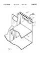
- FIG. 1is a perspective view of part of a coverage area, showing antennas and antenna connections.
- FIG. 2shows an in-building coverage area and a typical prior-art permanent antenna arrangement within the coverage area.
- FIG. 3illustrates a possible placement of test antennas within the coverage area of FIG. 2, according to the present invention.
- FIG. 4is a schematic diagram showing the strengths at a measurement location of the signals from test antennas such as the ones shown in FIG. 3, according to the present invention.
- FIG. 5shows a coverage area including part of an urban area, test antennas and measurement locations, according to the present invention.
- FIG. 6shows a possible optimum arrangement of permanent antennas in the in-building coverage area of FIG. 2, according to the present invention.
- FIG. 7is a schematic flowchart illustrating a method of selection of an optimal subset, according to the present invention.
- FIG. 8is a flowchart similar to that of FIG. 6, illustrating in more detail possible coverage parameters that can be used by a utility function, according to the present invention.
- FIG. 9is a schematic diagram of an apparatus of the present invention.
- FIG. 10shows a simplified plan of a building where test measurements were performed according to the present invention.
- FIG. 11-Ashows the power received from an antenna, along a path within the building illustrated in FIG. 10.
- FIG. 11-Bshows the power received form one another antenna, along the path of FIG. 11-A.
- FIG. 12-Ashows the total power received from a configuration of two antennas, along the path of FIG. 11-A.
- FIG. 12-Bshows the total power received from a configuration of three antennas, along the path of FIG. 11-A.
- FIG. 1shows a part of an in-building coverage area 20 for wireless communications, having a wall 22 and a floor 24.
- Coverage area 20is covered by a communications distribution system having a hub 26, a number of permanent antennas 30 and a number of links 32 connecting hub 26 to antennas 30.
- Links 32are typically copper cables, but in general can comprise any combination of copper cables and optical fibers. If the distance between hub 26 and an antenna 30 is short (tens of meters), link 34 is preferably a copper cable.
- Permanent antennas 30are typically antennas capable of sending and receiving signals in the radio-frequency (RF) range (up to 30 GHz), but can in general be antennas capable of communicating in millimeter wave (30-300 GHz) or optical (300 GHz-3 THz) frequencies.
- Hub 26is typically a base station for cellular or cordless telephony, although in general each of antennas 30 can be a base station.
- Coverage area 20comprises part of a building, including parts of different rooms within a floor, and parts of different floors.
- a method of the present inventioncan be applied as well in a complex urban or suburban area.
- a complex areais understood to mean any area having obstacles that shield a mobile user from electromagnetic fields. In such an area, the a priori prediction of the coverage provided by permanent antennas placed within the coverage area is very difficult.
- a permanent antennais understood to mean a base station antenna or a repeater antenna used during the normal operation of the communications distribution system.
- a method of the present inventionis particularly suited for the optimization of repeater placement inside buildings, and of base station placement in complex urban areas.
- FIG. 2shows schematically an in-building coverage area 40 having rooms 42, hallways 44 and walls 46.
- the coverage area showncomprises part of a single floor.
- FIG. 2illustrates a typical approach to providing coverage within an area such as area 40: permanent antennas 48 similar to antennas 30 are placed essentially in each room and hallway to ensure adequate coverage within area 40.
- an experienced engineerqualitatively decides on the placement of permanent antennas 48 using a floor plan of coverage area 40.
- a number of links 50connect antennas 48 to a hub 52 similar to hub 26.
- the typical approaches to antenna placementcan be costlier than necessary, and can lead to undesired interference between signals from different antennas 48, or to inadequate coverage of area 40 if too few antennas 48 are installed.
- a method of the present inventionallows the determination, before the installation of antennas 48, of an optimal subset from the set of potential installation sites for permanent antennas 48 in a coverage area such as area 40.
- test antennas 60are placed at test antenna sites within coverage area 40, as shown in FIG. 3.
- test antennas 60are similar in output characteristics (e.g. power, order of magnitude of frequency) to the permanent antennas to be installed.
- the test antenna sitesare chosen from the set of potential installation sites for permanent antennas 48 and the set of potential communication unit locations.
- the set of potential installation sitesincludes sites on ceilings, high on walls, above suspended ceilings, and in general any site where a permanent antenna 48 can be installed.
- the set of potential communications unit locationsincludes locations within coverage area 40 where a person having a communications unit may need to use the unit.
- An operatortemporarily attaches (for example with stick-on tape) test antennas 60 at test antenna sites, with one test antenna per site.
- a map or floor plan of coverage area 40is available to the operator.
- the maptypically comprises the walls of a building, but generally may include any obstacles that can influence the transmission of waves of the frequencies used in the communications network; for many applications, such frequencies are radio frequencies (up to 30 GHz).
- the operatorrecords the test antenna sites on the map, and the identity of the test antenna at each antenna site.
- one or two test antennasare placed in each room or hallway.
- a test antenna 60emits radio frequency (RF) signals distinguishable from those of other test antennas by a distinguishing factor.
- the distinguishing factorcan be the frequency of the signal from the antenna: a test antenna T 1 emits at a frequency f 1 , an antenna T 2 at f 2 , and an antenna T n at a frequency f n .
- the operatorwalks around coverage area 40 and measures the signal strengths from each of test antennas 60 at measurement locations 62, using an apparatus of the present invention.
- the signal strengths from test antennas 60 at a measurement location 62are then stored, and the measurement locations are preferably recorded on the map.
- Measurement locations 62are chosen from the set of potential installation sites for permanent antennas 48 and the set of potential communication unit locations. Allowing the test antenna sites to include potential communications unit locations, and measurement locations 62 to include potential installation sites is important because of the equivalence of test antenna sites and measurement locations.
- FIG. 4A schematic example of signal strengths at a measurement location from a set of fifteen antennas 60 is shown in FIG. 4. Antennas close to a measurement location 62 will yield a strong signal at that measurement location, while antennas far away will yield a weaker signal.
- the measurement stepis repeated at other measurement locations within the coverage area. Since the coverage provided by a typical test antenna arrangement (e.g. one test antenna per room) does not vary significantly over distances on the order of meters, it is usually enough to choose one or two measurement locations in each room or hallway in order to simulate the coverage provided virtually everywhere in the coverage area. In general, however, any number of measurement locations can be chosen, depending on the complexity of the coverage area and on the desired accuracy of the coverage simulation.
- FIG. 5shows a hypothetical map of part of a city including a coverage area 66 and roads 68. The part of the city shown is expected to be serviced by one or two base stations whose placement is to be determined.
- Test antennas 72are placed at test antenna sites within coverage area 66, and the signal strengths from test antennas 72 are measured at measurement locations 74.
- An operator having a measurement apparatus of the present inventionpreferably drives or walks along roads 68 and takes measurements of signal strengths.
- measurement locationsare not restricted to locations on roads. Suitable test antenna sites and measurement locations can easily be determined by the skilled artisan.
- FIG. 6shows a possible optimized arrangement for coverage area 40, where permanent antennas 48 are connected by a number of links 64 to hub 52.
- a preferred way to quantify a particular definition of an optimal subsetis to compute a utility function f for many subsets of sites, where f depends on a set of coverage parameters p1, p2, . . . , pm.
- the optimal subset (or subsets)is then defined as the subset(s) having an optimal (e.g. maximum) value of f.
- FIG. 7 and 8show simplified flowcharts of a method designed to select an optimal subset of installation sites based on a set of coverage parameters.
- a likely range for the number of permanent antennas needed to provide coverage to a coverage areacan be estimated from the size of the coverage area and the power output and effective range of a permanent antenna.
- the programchooses one number i in that range, and a subset of i test antennas/test antenna sites.
- the programthen calculates the value of a utility function f for that subset. If the number of test antenna sites and of measurement locations is so large as to make the evaluation of all subsets computationally impractical, it is possible to evaluate only a representative fraction of all possible subsets, for example by a Monte Carlo method.
- Some of the parameters that function f can depend onare shown in FIG. 8: they include the dimension of part of the coverage area, the relative communications importance/weight of part of the coverage area, the cost of a permanent antenna, the cost of installing permanent antennas at the sites of a given subset, performance parameters (such as dynamic range) of a link, the cost of a given link length, the coverage quality within part of the coverage area as measured by the signal strengths from test antennas at measurement points within that part, as well as any other parameters that are relevant to the performance and/or cost of the distributed network.
- the location of the hubcan be taken to be a fixed parameter, or can be factored in the utility function so as to minimize link lengths.
- the programdetermines for which subset(s) the utility function has an optimal value; that subset (or subsets) is/are then the optimal subset(s).
- the programfirst chooses coverage subsets for which the coverage provided meets a predetermined condition, and then selects an optimal subset from the coverage subsets as described above. For example, the program computes a coverage function; the subsets for which the coverage function meets a given condition (e.g., the value of the coverage function is non-zero) are then selected as coverage subsets.
- a database of measurements performed according to a method of the present inventionallows the prediction of coverage in new coverage areas without the need for measurements within the new coverage area.
- Parts of typical buildingscan be categorized in a finite number of architectural categories common to many buildings. Such categories include, among others: a hallway with a line of offices on either side of the hallway; a large open office space area with partitioned work areas; an elevator shaft leading into a lobby or reception area; a part of a building having a plan similar to that shown in FIG. 2; etc.
- Each categorycan have subcategories having narrower defining characteristics.
- the category offices on e with offices on either sidecan include a subcategory having a 6 foot wide hallway and a 10 foot high ceiling.
- many other categories and subcategoriescan be defined. In the ensuing description, the word category is understood for simplicity to encompass categories and subcategories.
- a coverage databasecontains indicators to maps of coverage categories, measurement locations and test antenna sites within the map, as well as the measured signal strengths at each location.
- An indicator to a mapmay be the map itself, or a reference to a map stored elsewhere.
- the databasealso contains computed optimal installation sites for each category.
- a coverage areamay include a hallway with offices on both sides, and a large open space office area.
- the stored coverage categories closest to the coverage area architectural categoriesare determined. In principle, there are many ways to determine which stored category is closest to an architectural category of interest. In a simple implementation such a determination can be performed by a comparison of building plans.
- the optimal subset of installation sites for the coverage areais then determined as described above, with the measurement data taken from the database instead of site measurements.
- the optimal subset for the coverage areamay be taken to be the union of the optimal subsets for each of the component categories of the coverage area; this approach, however, does not take into consideration the interactions between antennas within different categories, and can lead to a less than optimal antenna and link placement.
- an apparatus 80 of the present inventionpreferably includes test antennas 60 or 72, a receiver 82 for receiving signals from test antennas 60 or 72, measuring means 84 for measuring the strengths of the signals from test antennas 60 or 72, and storage means 86 for storing the signal strengths measured at each measurement location 62 or 74.
- Apparatus 80can also include a display 88 for displaying to the operator the signal strengths as they are measured. The measurement results are transferred to selection means 90 and an optimal subset of installation sites is selected as described above.
- receiver 82is an antenna suitable for receiving signals from test antennas 60 or 72.
- Measuring means 84can include an analog-to-digital converter, and storage means 86 can be a disk or computer memory.
- selection means 90is computer software used to practically implement a method of the present invention. Receivers, storage means, displays, and ways to make them are well known in the art. Methods and tools needed to build an apparatus of the present invention are well known to a person of average skill in the art.
- a maximal value of fis taken to be optimal.
- a set of measurement points m jand a set of signal strengths s jk , where s jk is the signal strength at point m j from a test antenna a k .
- a coverage subfunction C for a subset of antenna sitescan be ##EQU1##
- q jis a parameter measuring the quality of coverage at the point m j .
- q jcan be ##EQU2##
- S jis the second highest signal strength at m j . That is, the quality coefficient q j for a given point is: zero if the signal from at least one test antenna does not exceed a predetermined value a (condition 1); zero if the signal from at least one test antenna exceeds a predetermined value b (condition 2); zero if the second highest signal strength S j approaches the maximum signal strength at m j (condition 3); and the maximum signal strength at m j otherwise (condition 4).
- Condition 1ensures that at least one test antenna provides a strong enough signal at m j , while condition 2 marks the subsets that produce too strong a signal at m j .
- Condition 3is designed to penalize subsets that produce excessive interference at m j , while condition 4 assigns a value to q j.
- a parameter such as q jcan have many forms, depending on the application.
- Conditions such as 1-4can also have many forms; in particular, a more sophisticated condition than condition 3 can be used to check for interference between antennas. Methods for evaluating coverage quality and interference are well known in the art.
- a utility function fcan consider only those subsets for which the coverage subfunction C is non-zero; such a method would in effect choose coverage subsets from the set of all subsets, where test antennas placed at the sites of a coverage subset provide coverage at all measurement points 62 or 74.
- a utility function fcan also depend on other parameters or subfunctions for each subset.
- fmay have a cost subfunction D depending on the cost of installing permanent antennas 48 at the sites of a subset, including the hardware costs of permanent antennas 48 and the costs of links 64.
- a coverage subfunctionsuch as the subfunction C described in Example 1 may also depend on a link subfunction L that estimates the effects of the lengths of links 64 on the signals from permanent antennas 48.
- a subfunction Lmay correct the signal strengths s jk in formula 2 using a set of factors l k , where l k depends on the distance between hub 52 and antenna a k .
- a quality coefficient q jcould then have a form similar to [2], with s jk replaced by l k sj k .
- a fiber optic link with 120 db dynamic rangecosts about 10 times more, and can deliver signals three orders of magnitude stronger than a fiber optic link with a 90 db dynamic range.
- Using 120 db links instead of 90 db linksthus reduces the number of links and permanent antennas to be installed, but raises the cost per link.
- FIG. 10shows a simplified plan of a building where test measurements were performed. Test antennas 100, 102, and 104 were placed at sites in a hallway, and the signals from the test antennas were measured at measurement locations along a path 106.
- FIG. 11-A and FIG. 11-Bshow the received powers from antennas 100 and 102 along path 106; for clarity of presentation, the graphs shown are space-averaged.
- antenna 100 alone configuration 1antennas 100 and 102 (configuration 2) and antennas 100, 102 and 104 (configuration 3).
- the total received powers along path 106 for configurations 2 and 3are shown in FIG. 12-A and FIG. 12-B, respectively.
- the ranges of the received powers, the required spur-free dynamic ranges (SFDR), and the percentages of path 106 defined to be "over-covered”are listed in Table 1 for each configuration:
- the choice of configurationdepends in general on what is considered optimal for the particular application. For the example above, the optimal configuration was chosen to be configuration 2.
- Previous field strength measurementscan be used in many ways for the determination of an optimal subset in a new area. Some possible ways include, listed in increasing order of sophistication and accuracy:
- the optimal subset for the new areais chosen to be substantially identical to a previously determined optimal subset for the old area.
- the optimal subset for the new areais chosen using a new utility function tailored to the new area. For example, architecturally similar rooms may have different functions in the new area than in the old area; such functions would be reflected in the weighting coefficients w j described in Example 1.
- the old field strength measurementsare scaled to the dimensions of the new area. Such a scaling can be done for example by taking into account the 1/r 2 decay of signals in free space.
- the new optimal subsetis computed using the scaled measurements.
- the new areais broken down into stored architectural categories.
- the stored architectural categoriesare overlapping, so that interactions between antennas in different categories can be taken into account.
- a utility functionis then optimized using the stored results from all the component categories. Such an optimization method takes into account interactions between antennas in different categories.
Landscapes
- Physics & Mathematics (AREA)
- Electromagnetism (AREA)
- General Physics & Mathematics (AREA)
- Mobile Radio Communication Systems (AREA)
Abstract
Description
TABLE 1 ______________________________________CONFIGURATION 1 2 3 ______________________________________ Range of Received 68.0 35.7 23.0 Powers (db) Required SFDR 115.8 83.5 70.8 (db-Hz.sup.2/3) Percent of Path 0 2.8 39.5 Over-Covered (%) ______________________________________
Claims (30)
Priority Applications (3)
| Application Number | Priority Date | Filing Date | Title |
|---|---|---|---|
| US08/635,300US5668562A (en) | 1996-04-19 | 1996-04-19 | Measurement-based method of optimizing the placement of antennas in a RF distribution system |
| AU27419/97AAU2741997A (en) | 1996-04-19 | 1997-04-18 | Antennas in an rf distribution system |
| PCT/US1997/006878WO1997040547A1 (en) | 1996-04-19 | 1997-04-18 | Antennas in an rf distribution system |
Applications Claiming Priority (1)
| Application Number | Priority Date | Filing Date | Title |
|---|---|---|---|
| US08/635,300US5668562A (en) | 1996-04-19 | 1996-04-19 | Measurement-based method of optimizing the placement of antennas in a RF distribution system |
Publications (1)
| Publication Number | Publication Date |
|---|---|
| US5668562Atrue US5668562A (en) | 1997-09-16 |
Family
ID=24547236
Family Applications (1)
| Application Number | Title | Priority Date | Filing Date |
|---|---|---|---|
| US08/635,300Expired - LifetimeUS5668562A (en) | 1996-04-19 | 1996-04-19 | Measurement-based method of optimizing the placement of antennas in a RF distribution system |
Country Status (3)
| Country | Link |
|---|---|
| US (1) | US5668562A (en) |
| AU (1) | AU2741997A (en) |
| WO (1) | WO1997040547A1 (en) |
Cited By (136)
| Publication number | Priority date | Publication date | Assignee | Title |
|---|---|---|---|---|
| US6104936A (en)* | 1997-09-30 | 2000-08-15 | Telefonaktiebolaget Lm Ericsson | Method and apparatus for optimizing antenna tilt |
| WO2000057510A1 (en)* | 1999-03-24 | 2000-09-28 | Diator Netcom Consultants Ab | Method and device at a transmitter and receiver unit in a mobile telephone system |
| US6151480A (en)* | 1997-06-27 | 2000-11-21 | Adc Telecommunications, Inc. | System and method for distributing RF signals over power lines within a substantially closed environment |
| WO2001041486A1 (en)* | 1999-12-03 | 2001-06-07 | Nokia Corporation | Measuring of the coverage area of a base transceiver station |
| US20010051503A1 (en)* | 2000-06-12 | 2001-12-13 | Lush Christa S. | System and method of planning and designing a broadband wireless network |
| WO2001078326A3 (en)* | 2000-04-10 | 2002-08-08 | Univ Carnegie Mellon | Method for configuring and assigning channels for a wireless network |
| US6445912B1 (en) | 1999-06-23 | 2002-09-03 | At&T Wireless Services, Inc. | System and method for checking service availability |
| WO2001078327A3 (en)* | 2000-04-10 | 2002-09-19 | Univ Carnegie Mellon | Method for configuring a wireless network |
| WO2001080500A3 (en)* | 2000-04-10 | 2002-10-10 | Univ Carnegie Mellon | Method for assigning channels for access points of a wireless network |
| US6487414B1 (en) | 2000-08-10 | 2002-11-26 | Schema Ltd. | System and method for frequency planning in wireless communication networks |
| WO2002060206A3 (en)* | 2000-10-26 | 2003-01-03 | Bellsouth Intellect Pty Corp | Mobile transmitter locator |
| US20030040329A1 (en)* | 2001-05-10 | 2003-02-27 | Eli Yona | Method and an apparatus for installing a communication system using active combiner/splitters |
| US20030157940A1 (en)* | 2000-04-13 | 2003-08-21 | Justin Howard | Method of mapping into triangles an area of wireless lan and portable device thereof |
| US6684055B1 (en)* | 2000-01-18 | 2004-01-27 | Otis Elevator Company | System for remotely communicating voice and data to and from an elevator controller |
| US6687640B1 (en)* | 2001-10-23 | 2004-02-03 | Sandia Corporation | Airborne agent concentration analysis |
| US6771966B1 (en)* | 1999-03-29 | 2004-08-03 | Carriercomm, Inc. | System and method for an automated radio network planning tool |
| US20050164712A1 (en)* | 2001-01-16 | 2005-07-28 | Kennedy Joseph P.Jr. | Method and system for applying wireless geolocation technology |
| US6940838B1 (en) | 1999-08-19 | 2005-09-06 | Invertix Corporation | Wireless telephone network optimization |
| US20060046646A1 (en)* | 2004-08-27 | 2006-03-02 | International Business Machines Corporation | Method and system for deploying a wireless repeater |
| US20060287762A1 (en)* | 2005-06-16 | 2006-12-21 | Masatoshi Takada | Method and apparatus for planning the installation position of RFID tags |
| US7177650B1 (en) | 1999-08-04 | 2007-02-13 | Clearwire Corporation | Method and apparatus for use in reducing overutilization of RF communication system resources |
| US20070286599A1 (en)* | 2006-06-12 | 2007-12-13 | Michael Sauer | Centralized optical-fiber-based wireless picocellular systems and methods |
| US20080014948A1 (en)* | 2006-07-14 | 2008-01-17 | Lgc Wireless, Inc. | System for and method of for providing dedicated capacity in a cellular network |
| US20080057873A1 (en)* | 2005-08-29 | 2008-03-06 | International Business Machines Corporation | Method of indoor radio planning |
| US20080058018A1 (en)* | 2006-08-29 | 2008-03-06 | Lgc Wireless, Inc. | Distributed antenna communications system and methods of implementing thereof |
| US20080151846A1 (en)* | 2006-12-22 | 2008-06-26 | Stefan Scheinert | System for and method of providing remote coverage area for wireless communications |
| US20080181171A1 (en)* | 2007-01-25 | 2008-07-31 | Adc Telecommunications, Inc. | Distributed remote base station system |
| US20080181282A1 (en)* | 2007-01-25 | 2008-07-31 | Adc Telecommunications, Inc. | Modular wireless communications platform |
| US20080232328A1 (en)* | 2007-03-23 | 2008-09-25 | Stefan Scheinert | Localization of a mobile device in distributed antenna communications system |
| US20080232305A1 (en)* | 2006-12-19 | 2008-09-25 | Yair Oren | Distributed Antenna System for MIMO Technologies |
| US20090005096A1 (en)* | 2007-06-26 | 2009-01-01 | Stefan Scheinert | Distributed antenna communications system |
| US20090061939A1 (en)* | 2007-08-29 | 2009-03-05 | Telefonaktiebolaget Lm Ericsson (Publ) | System and method for indoor coverage of user equipment terminals |
| US20090061940A1 (en)* | 2007-08-31 | 2009-03-05 | Stefan Scheinert | System for and method of configuring distributed antenna communications system |
| US7590354B2 (en) | 2006-06-16 | 2009-09-15 | Corning Cable Systems Llc | Redundant transponder array for a radio-over-fiber optical fiber cable |
| AU2004260484B2 (en)* | 2003-07-21 | 2009-11-19 | Google Llc | Multi-user call waiting |
| US7627250B2 (en) | 2006-08-16 | 2009-12-01 | Corning Cable Systems Llc | Radio-over-fiber transponder with a dual-band patch antenna system |
| US7693042B1 (en)* | 1999-06-23 | 2010-04-06 | At&T Mobility Ii Llc | Intelligent presentation network management system |
| US7787823B2 (en) | 2006-09-15 | 2010-08-31 | Corning Cable Systems Llc | Radio-over-fiber (RoF) optical fiber cable system with transponder diversity and RoF wireless picocellular system using same |
| US7805073B2 (en) | 2006-04-28 | 2010-09-28 | Adc Telecommunications, Inc. | Systems and methods of optical path protection for distributed antenna systems |
| US7848654B2 (en) | 2006-09-28 | 2010-12-07 | Corning Cable Systems Llc | Radio-over-fiber (RoF) wireless picocellular system with combined picocells |
| US7873363B1 (en)* | 2006-02-22 | 2011-01-18 | Hieb Mario K | Method for identifying unique FM transmitter locations with enhanced transmission coverage |
| US20110200325A1 (en)* | 2010-02-15 | 2011-08-18 | Andrey Kobyakov | Dynamic Cell Bonding (DCB) for Radio-over-Fiber (RoF)-Based Networks and Communication Systems and Related Methods |
| US8111998B2 (en) | 2007-02-06 | 2012-02-07 | Corning Cable Systems Llc | Transponder systems and methods for radio-over-fiber (RoF) wireless picocellular systems |
| WO2012036640A1 (en)* | 2010-09-17 | 2012-03-22 | Consistel Pte Ltd | Automatic network design |
| US8175459B2 (en) | 2007-10-12 | 2012-05-08 | Corning Cable Systems Llc | Hybrid wireless/wired RoF transponder and hybrid RoF communication system using same |
| US8224241B1 (en) | 2007-07-05 | 2012-07-17 | Nextel Communications Inc. | System and method for antenna orientation for mobile applications |
| US8254848B1 (en)* | 2011-12-09 | 2012-08-28 | At&T Intellectual Property I, Lp | Monitoring system for distributed antenna systems |
| US8295777B1 (en)* | 2009-06-19 | 2012-10-23 | Sprint Spectrum L.P. | Method and system for automated handoff testing |
| US8428511B1 (en) | 2007-08-10 | 2013-04-23 | Nextel Communications Inc. | System and method for a high available and survivable communication system |
| US8532492B2 (en) | 2009-02-03 | 2013-09-10 | Corning Cable Systems Llc | Optical fiber-based distributed antenna systems, components, and related methods for calibration thereof |
| US8548330B2 (en) | 2009-07-31 | 2013-10-01 | Corning Cable Systems Llc | Sectorization in distributed antenna systems, and related components and methods |
| US20130260705A1 (en)* | 2012-03-29 | 2013-10-03 | Lgc Wireless, Llc | Systems and methods for adjusting system tests based on detected interference |
| US8639121B2 (en) | 2009-11-13 | 2014-01-28 | Corning Cable Systems Llc | Radio-over-fiber (RoF) system for protocol-independent wired and/or wireless communication |
| US8644844B2 (en) | 2007-12-20 | 2014-02-04 | Corning Mobileaccess Ltd. | Extending outdoor location based services and applications into enclosed areas |
| US20140129293A1 (en)* | 2012-11-08 | 2014-05-08 | xAd, Inc. | Method and Apparatus for Dynamic Fencing |
| US8867919B2 (en) | 2007-07-24 | 2014-10-21 | Corning Cable Systems Llc | Multi-port accumulator for radio-over-fiber (RoF) wireless picocellular systems |
| US8983301B2 (en) | 2010-03-31 | 2015-03-17 | Corning Optical Communications LLC | Localization services in optical fiber-based distributed communications components and systems, and related methods |
| US9037143B2 (en) | 2010-08-16 | 2015-05-19 | Corning Optical Communications LLC | Remote antenna clusters and related systems, components, and methods supporting digital data signal propagation between remote antenna units |
| US9042732B2 (en) | 2010-05-02 | 2015-05-26 | Corning Optical Communications LLC | Providing digital data services in optical fiber-based distributed radio frequency (RF) communication systems, and related components and methods |
| US9106286B2 (en) | 2000-06-13 | 2015-08-11 | Comcast Cable Communications, Llc | Network communication using diversity |
| US9158864B2 (en) | 2012-12-21 | 2015-10-13 | Corning Optical Communications Wireless Ltd | Systems, methods, and devices for documenting a location of installed equipment |
| US9178635B2 (en) | 2014-01-03 | 2015-11-03 | Corning Optical Communications Wireless Ltd | Separation of communication signal sub-bands in distributed antenna systems (DASs) to reduce interference |
| US9185674B2 (en) | 2010-08-09 | 2015-11-10 | Corning Cable Systems Llc | Apparatuses, systems, and methods for determining location of a mobile device(s) in a distributed antenna system(s) |
| US9184843B2 (en) | 2011-04-29 | 2015-11-10 | Corning Optical Communications LLC | Determining propagation delay of communications in distributed antenna systems, and related components, systems, and methods |
| US9240835B2 (en) | 2011-04-29 | 2016-01-19 | Corning Optical Communications LLC | Systems, methods, and devices for increasing radio frequency (RF) power in distributed antenna systems |
| US9247543B2 (en) | 2013-07-23 | 2016-01-26 | Corning Optical Communications Wireless Ltd | Monitoring non-supported wireless spectrum within coverage areas of distributed antenna systems (DASs) |
| US9258052B2 (en) | 2012-03-30 | 2016-02-09 | Corning Optical Communications LLC | Reducing location-dependent interference in distributed antenna systems operating in multiple-input, multiple-output (MIMO) configuration, and related components, systems, and methods |
| US9325429B2 (en) | 2011-02-21 | 2016-04-26 | Corning Optical Communications LLC | Providing digital data services as electrical signals and radio-frequency (RF) communications over optical fiber in distributed communications systems, and related components and methods |
| US9357551B2 (en) | 2014-05-30 | 2016-05-31 | Corning Optical Communications Wireless Ltd | Systems and methods for simultaneous sampling of serial digital data streams from multiple analog-to-digital converters (ADCS), including in distributed antenna systems |
| US9385810B2 (en) | 2013-09-30 | 2016-07-05 | Corning Optical Communications Wireless Ltd | Connection mapping in distributed communication systems |
| US9420542B2 (en) | 2014-09-25 | 2016-08-16 | Corning Optical Communications Wireless Ltd | System-wide uplink band gain control in a distributed antenna system (DAS), based on per band gain control of remote uplink paths in remote units |
| US9419712B2 (en) | 2010-10-13 | 2016-08-16 | Ccs Technology, Inc. | Power management for remote antenna units in distributed antenna systems |
| US9455784B2 (en) | 2012-10-31 | 2016-09-27 | Corning Optical Communications Wireless Ltd | Deployable wireless infrastructures and methods of deploying wireless infrastructures |
| US9497706B2 (en) | 2013-02-20 | 2016-11-15 | Corning Optical Communications Wireless Ltd | Power management in distributed antenna systems (DASs), and related components, systems, and methods |
| US9509133B2 (en) | 2014-06-27 | 2016-11-29 | Corning Optical Communications Wireless Ltd | Protection of distributed antenna systems |
| US9525472B2 (en) | 2014-07-30 | 2016-12-20 | Corning Incorporated | Reducing location-dependent destructive interference in distributed antenna systems (DASS) operating in multiple-input, multiple-output (MIMO) configuration, and related components, systems, and methods |
| US9525488B2 (en) | 2010-05-02 | 2016-12-20 | Corning Optical Communications LLC | Digital data services and/or power distribution in optical fiber-based distributed communications systems providing digital data and radio frequency (RF) communications services, and related components and methods |
| US9531452B2 (en) | 2012-11-29 | 2016-12-27 | Corning Optical Communications LLC | Hybrid intra-cell / inter-cell remote unit antenna bonding in multiple-input, multiple-output (MIMO) distributed antenna systems (DASs) |
| US9565596B2 (en) | 2011-08-29 | 2017-02-07 | Commscope Technologies Llc | Configuring a distributed antenna system |
| US20170041807A1 (en)* | 2015-08-03 | 2017-02-09 | Nextivity, Inc. | Determining the optimum coverage position in a building for externally provided rf signals |
| US9590733B2 (en) | 2009-07-24 | 2017-03-07 | Corning Optical Communications LLC | Location tracking using fiber optic array cables and related systems and methods |
| US9602210B2 (en) | 2014-09-24 | 2017-03-21 | Corning Optical Communications Wireless Ltd | Flexible head-end chassis supporting automatic identification and interconnection of radio interface modules and optical interface modules in an optical fiber-based distributed antenna system (DAS) |
| US9621293B2 (en) | 2012-08-07 | 2017-04-11 | Corning Optical Communications Wireless Ltd | Distribution of time-division multiplexed (TDM) management services in a distributed antenna system, and related components, systems, and methods |
| US9647758B2 (en) | 2012-11-30 | 2017-05-09 | Corning Optical Communications Wireless Ltd | Cabling connectivity monitoring and verification |
| US9648580B1 (en) | 2016-03-23 | 2017-05-09 | Corning Optical Communications Wireless Ltd | Identifying remote units in a wireless distribution system (WDS) based on assigned unique temporal delay patterns |
| US9653861B2 (en) | 2014-09-17 | 2017-05-16 | Corning Optical Communications Wireless Ltd | Interconnection of hardware components |
| US9661781B2 (en) | 2013-07-31 | 2017-05-23 | Corning Optical Communications Wireless Ltd | Remote units for distributed communication systems and related installation methods and apparatuses |
| US9673904B2 (en) | 2009-02-03 | 2017-06-06 | Corning Optical Communications LLC | Optical fiber-based distributed antenna systems, components, and related methods for calibration thereof |
| US9681313B2 (en) | 2015-04-15 | 2017-06-13 | Corning Optical Communications Wireless Ltd | Optimizing remote antenna unit performance using an alternative data channel |
| US9681396B2 (en) | 2014-01-30 | 2017-06-13 | Commscope Technologies Llc | Power allocation in distributed antenna systems based on key performance indicators |
| US9685782B2 (en) | 2010-11-24 | 2017-06-20 | Corning Optical Communications LLC | Power distribution module(s) capable of hot connection and/or disconnection for distributed antenna systems, and related power units, components, and methods |
| US9699723B2 (en) | 2010-10-13 | 2017-07-04 | Ccs Technology, Inc. | Local power management for remote antenna units in distributed antenna systems |
| US9715157B2 (en) | 2013-06-12 | 2017-07-25 | Corning Optical Communications Wireless Ltd | Voltage controlled optical directional coupler |
| US9730228B2 (en) | 2014-08-29 | 2017-08-08 | Corning Optical Communications Wireless Ltd | Individualized gain control of remote uplink band paths in a remote unit in a distributed antenna system (DAS), based on combined uplink power level in the remote unit |
| US9729251B2 (en) | 2012-07-31 | 2017-08-08 | Corning Optical Communications LLC | Cooling system control in distributed antenna systems |
| US9729267B2 (en) | 2014-12-11 | 2017-08-08 | Corning Optical Communications Wireless Ltd | Multiplexing two separate optical links with the same wavelength using asymmetric combining and splitting |
| US9775123B2 (en) | 2014-03-28 | 2017-09-26 | Corning Optical Communications Wireless Ltd. | Individualized gain control of uplink paths in remote units in a distributed antenna system (DAS) based on individual remote unit contribution to combined uplink power |
| WO2017106046A3 (en)* | 2015-12-17 | 2017-09-28 | Belkin International, Inc. | Optimizing placement of a wireless range extender |
| US9781553B2 (en) | 2012-04-24 | 2017-10-03 | Corning Optical Communications LLC | Location based services in a distributed communication system, and related components and methods |
| US9785175B2 (en) | 2015-03-27 | 2017-10-10 | Corning Optical Communications Wireless, Ltd. | Combining power from electrically isolated power paths for powering remote units in a distributed antenna system(s) (DASs) |
| US9807700B2 (en) | 2015-02-19 | 2017-10-31 | Corning Optical Communications Wireless Ltd | Offsetting unwanted downlink interference signals in an uplink path in a distributed antenna system (DAS) |
| US9843947B2 (en) | 2015-01-14 | 2017-12-12 | Kcf Technologies, Inc. | Visual signal strength indication for a wireless device |
| US9948349B2 (en) | 2015-07-17 | 2018-04-17 | Corning Optical Communications Wireless Ltd | IOT automation and data collection system |
| US9974074B2 (en) | 2013-06-12 | 2018-05-15 | Corning Optical Communications Wireless Ltd | Time-division duplexing (TDD) in distributed communications systems, including distributed antenna systems (DASs) |
| US9980269B2 (en) | 2014-01-30 | 2018-05-22 | Commscope Technologies Llc | Optimizing power allocation in signal distribution systems using variable and static gains |
| US10050728B2 (en) | 2015-04-08 | 2018-08-14 | Corning Optical Communications LLC | Simulating service changes in an application module (AM) in a wireless communications system (WCS) to simulate site walks in the wireless communications system |
| WO2018182823A1 (en)* | 2017-03-31 | 2018-10-04 | Intel IP Corporation | Communication network controller and method |
| US10096909B2 (en) | 2014-11-03 | 2018-10-09 | Corning Optical Communications Wireless Ltd. | Multi-band monopole planar antennas configured to facilitate improved radio frequency (RF) isolation in multiple-input multiple-output (MIMO) antenna arrangement |
| US10110308B2 (en) | 2014-12-18 | 2018-10-23 | Corning Optical Communications Wireless Ltd | Digital interface modules (DIMs) for flexibly distributing digital and/or analog communications signals in wide-area analog distributed antenna systems (DASs) |
| US10128951B2 (en) | 2009-02-03 | 2018-11-13 | Corning Optical Communications LLC | Optical fiber-based distributed antenna systems, components, and related methods for monitoring and configuring thereof |
| US10136200B2 (en) | 2012-04-25 | 2018-11-20 | Corning Optical Communications LLC | Distributed antenna system architectures |
| US10135533B2 (en) | 2014-11-13 | 2018-11-20 | Corning Optical Communications Wireless Ltd | Analog distributed antenna systems (DASS) supporting distribution of digital communications signals interfaced from a digital signal source and analog radio frequency (RF) communications signals |
| US10153814B1 (en)* | 2017-06-13 | 2018-12-11 | Corning Incorporated | Massive multiple-input multiple-output (M-MIMO) wireless distribution system (WDS) and related methods for optimizing the M-MIMO WDS |
| EP3415934A1 (en)* | 2017-06-13 | 2018-12-19 | Swiss Timing Ltd. | Method for estimating the covered area of a directive antenna of a local positioning system while setting up said system |
| US10187151B2 (en) | 2014-12-18 | 2019-01-22 | Corning Optical Communications Wireless Ltd | Digital-analog interface modules (DAIMs) for flexibly distributing digital and/or analog communications signals in wide-area analog distributed antenna systems (DASs) |
| US10230326B2 (en) | 2015-03-24 | 2019-03-12 | Carrier Corporation | System and method for energy harvesting system planning and performance |
| US10236924B2 (en) | 2016-03-31 | 2019-03-19 | Corning Optical Communications Wireless Ltd | Reducing out-of-channel noise in a wireless distribution system (WDS) |
| US10257056B2 (en) | 2012-11-28 | 2019-04-09 | Corning Optical Communications LLC | Power management for distributed communication systems, and related components, systems, and methods |
| CN109862586A (en)* | 2019-03-02 | 2019-06-07 | 湖南城市学院 | A simulation system and method for realizing wireless network communication field strength coverage |
| US10455497B2 (en) | 2013-11-26 | 2019-10-22 | Corning Optical Communications LLC | Selective activation of communications services on power-up of a remote unit(s) in a wireless communication system (WCS) based on power consumption |
| US10459593B2 (en) | 2015-03-24 | 2019-10-29 | Carrier Corporation | Systems and methods for providing a graphical user interface indicating intruder threat levels for a building |
| US10499269B2 (en) | 2015-11-12 | 2019-12-03 | Commscope Technologies Llc | Systems and methods for assigning controlled nodes to channel interfaces of a controller |
| US10560214B2 (en) | 2015-09-28 | 2020-02-11 | Corning Optical Communications LLC | Downlink and uplink communication path switching in a time-division duplex (TDD) distributed antenna system (DAS) |
| US10606963B2 (en) | 2015-03-24 | 2020-03-31 | Carrier Corporation | System and method for capturing and analyzing multidimensional building information |
| US10621527B2 (en) | 2015-03-24 | 2020-04-14 | Carrier Corporation | Integrated system for sales, installation, and maintenance of building systems |
| US10654588B2 (en) | 2014-04-02 | 2020-05-19 | Sikorsky Aircraft Corporation | Rotor wireless load and motion monitoring sensor network |
| US10659163B2 (en) | 2014-09-25 | 2020-05-19 | Corning Optical Communications LLC | Supporting analog remote antenna units (RAUs) in digital distributed antenna systems (DASs) using analog RAU digital adaptors |
| US10756830B2 (en) | 2015-03-24 | 2020-08-25 | Carrier Corporation | System and method for determining RF sensor performance relative to a floor plan |
| US10756818B2 (en) | 2014-06-02 | 2020-08-25 | Belkin International, Inc. | Optimizing placement of a wireless range extender |
| US10928785B2 (en) | 2015-03-24 | 2021-02-23 | Carrier Corporation | Floor plan coverage based auto pairing and parameter setting |
| US10944837B2 (en) | 2015-03-24 | 2021-03-09 | Carrier Corporation | Floor-plan based learning and registration of distributed devices |
| US10992484B2 (en) | 2013-08-28 | 2021-04-27 | Corning Optical Communications LLC | Power management for distributed communication systems, and related components, systems, and methods |
| US11036897B2 (en) | 2015-03-24 | 2021-06-15 | Carrier Corporation | Floor plan based planning of building systems |
| US11163921B1 (en)* | 2020-09-01 | 2021-11-02 | TeleqoTech | Managing a smart city |
| US11296504B2 (en) | 2010-11-24 | 2022-04-05 | Corning Optical Communications LLC | Power distribution module(s) capable of hot connection and/or disconnection for wireless communication systems, and related power units, components, and methods |
| US11445379B2 (en)* | 2020-09-29 | 2022-09-13 | At&T Intellectual Property I, L.P. | Facilitating heterogeneous network analysis and resource planning for advanced networks |
Families Citing this family (4)
| Publication number | Priority date | Publication date | Assignee | Title |
|---|---|---|---|---|
| KR20020073013A (en)* | 2001-03-14 | 2002-09-19 | 에스케이 텔레콤주식회사 | In-building wireless call quality management method on website |
| EP1806559A1 (en)* | 2006-01-10 | 2007-07-11 | Leica Geosystems AG | Surveying procedure and system for a high-rise structure |
| CN101183893B (en)* | 2007-12-17 | 2011-06-01 | 中国移动通信集团北京有限公司 | Simulation method and device for wireless communication network |
| CN101247613B (en)* | 2008-03-11 | 2012-07-18 | 中兴通讯股份有限公司 | Wireless signal propagation model test approach and system used for honeycomb network |
Citations (6)
| Publication number | Priority date | Publication date | Assignee | Title |
|---|---|---|---|---|
| US5151704A (en)* | 1989-09-29 | 1992-09-29 | Televerket | Method for simulating the effect of alternative antenna patterns on the coverage and interference pattern of a mobile radio system |
| US5179722A (en)* | 1989-12-18 | 1993-01-12 | Krister Gunmar | Method for determining multiple interference in a mobile radio system |
| US5293640A (en)* | 1989-03-03 | 1994-03-08 | Televerket | Method for planning radio cells |
| US5321736A (en)* | 1992-01-03 | 1994-06-14 | Pcs Microcell International Inc. | Distributed RF repeater arrangement for cordless telephones |
| US5381444A (en)* | 1991-10-31 | 1995-01-10 | Fujitsu Limited | Radio environment measuring system |
| US5507010A (en)* | 1992-12-30 | 1996-04-09 | Nokia Telecommunications Oy | Arrangement for measuring at frequencies actually used for signalling, the condition of a receiving antenna positioned apart from other base station equipment at a base station of a radio system |
- 1996
- 1996-04-19USUS08/635,300patent/US5668562A/ennot_activeExpired - Lifetime
- 1997
- 1997-04-18WOPCT/US1997/006878patent/WO1997040547A1/enactiveApplication Filing
- 1997-04-18AUAU27419/97Apatent/AU2741997A/ennot_activeAbandoned
Patent Citations (6)
| Publication number | Priority date | Publication date | Assignee | Title |
|---|---|---|---|---|
| US5293640A (en)* | 1989-03-03 | 1994-03-08 | Televerket | Method for planning radio cells |
| US5151704A (en)* | 1989-09-29 | 1992-09-29 | Televerket | Method for simulating the effect of alternative antenna patterns on the coverage and interference pattern of a mobile radio system |
| US5179722A (en)* | 1989-12-18 | 1993-01-12 | Krister Gunmar | Method for determining multiple interference in a mobile radio system |
| US5381444A (en)* | 1991-10-31 | 1995-01-10 | Fujitsu Limited | Radio environment measuring system |
| US5321736A (en)* | 1992-01-03 | 1994-06-14 | Pcs Microcell International Inc. | Distributed RF repeater arrangement for cordless telephones |
| US5507010A (en)* | 1992-12-30 | 1996-04-09 | Nokia Telecommunications Oy | Arrangement for measuring at frequencies actually used for signalling, the condition of a receiving antenna positioned apart from other base station equipment at a base station of a radio system |
Cited By (276)
| Publication number | Priority date | Publication date | Assignee | Title |
|---|---|---|---|---|
| US6151480A (en)* | 1997-06-27 | 2000-11-21 | Adc Telecommunications, Inc. | System and method for distributing RF signals over power lines within a substantially closed environment |
| US6104936A (en)* | 1997-09-30 | 2000-08-15 | Telefonaktiebolaget Lm Ericsson | Method and apparatus for optimizing antenna tilt |
| AU767813B2 (en)* | 1999-03-24 | 2003-11-27 | Diator Netcom Consultants Ab | Method and device at a transmitter and receiver unit in a mobile telephone system |
| WO2000057510A1 (en)* | 1999-03-24 | 2000-09-28 | Diator Netcom Consultants Ab | Method and device at a transmitter and receiver unit in a mobile telephone system |
| US6801753B1 (en) | 1999-03-24 | 2004-10-05 | Diator Netcom Consultants Ab | Method and device at a transmitter and receiver unit in a mobile telephone system |
| RU2237321C2 (en)* | 1999-03-24 | 2004-09-27 | Диатор Нетком Консультантс Аб | Method and device for using mobile telephone communication system transceiver unit |
| US6771966B1 (en)* | 1999-03-29 | 2004-08-03 | Carriercomm, Inc. | System and method for an automated radio network planning tool |
| US6445912B1 (en) | 1999-06-23 | 2002-09-03 | At&T Wireless Services, Inc. | System and method for checking service availability |
| US7693042B1 (en)* | 1999-06-23 | 2010-04-06 | At&T Mobility Ii Llc | Intelligent presentation network management system |
| US7177650B1 (en) | 1999-08-04 | 2007-02-13 | Clearwire Corporation | Method and apparatus for use in reducing overutilization of RF communication system resources |
| US6940838B1 (en) | 1999-08-19 | 2005-09-06 | Invertix Corporation | Wireless telephone network optimization |
| US7248876B2 (en) | 1999-12-03 | 2007-07-24 | Nokia Corporation | Measuring of the coverage area of a base transceiver station |
| US20060234640A1 (en)* | 1999-12-03 | 2006-10-19 | Nokia Corporation | Measuring of the coverage area of a base transceiver station |
| WO2001041486A1 (en)* | 1999-12-03 | 2001-06-07 | Nokia Corporation | Measuring of the coverage area of a base transceiver station |
| US7076252B1 (en) | 1999-12-03 | 2006-07-11 | Nokia Corporation | Measuring of the coverage area of a base transceiver station |
| US6684055B1 (en)* | 2000-01-18 | 2004-01-27 | Otis Elevator Company | System for remotely communicating voice and data to and from an elevator controller |
| US6711148B1 (en)* | 2000-04-10 | 2004-03-23 | Carnegie Mellon University | Method for configuring a wireless network |
| US6505045B1 (en) | 2000-04-10 | 2003-01-07 | Carnegie Mellon University | Method for configuring and assigning channels for a wireless network |
| WO2001080500A3 (en)* | 2000-04-10 | 2002-10-10 | Univ Carnegie Mellon | Method for assigning channels for access points of a wireless network |
| WO2001078327A3 (en)* | 2000-04-10 | 2002-09-19 | Univ Carnegie Mellon | Method for configuring a wireless network |
| WO2001078326A3 (en)* | 2000-04-10 | 2002-08-08 | Univ Carnegie Mellon | Method for configuring and assigning channels for a wireless network |
| US6636737B1 (en) | 2000-04-10 | 2003-10-21 | Carnegie Mellon University | Method for assigning channels for access points of a wireless network |
| US7205992B2 (en)* | 2000-04-13 | 2007-04-17 | Nokia Corporation | Method of mapping into triangles an area of wireless lan and portable device thereof |
| US20030157940A1 (en)* | 2000-04-13 | 2003-08-21 | Justin Howard | Method of mapping into triangles an area of wireless lan and portable device thereof |
| US20010051503A1 (en)* | 2000-06-12 | 2001-12-13 | Lush Christa S. | System and method of planning and designing a broadband wireless network |
| US9209871B2 (en) | 2000-06-13 | 2015-12-08 | Comcast Cable Communications, Llc | Network communication using diversity |
| US9356666B1 (en) | 2000-06-13 | 2016-05-31 | Comcast Cable Communications, Llc | Originator and recipient based transmissions in wireless communications |
| US9654323B2 (en) | 2000-06-13 | 2017-05-16 | Comcast Cable Communications, Llc | Data routing for OFDM transmission based on observed node capacities |
| USRE45775E1 (en) | 2000-06-13 | 2015-10-20 | Comcast Cable Communications, Llc | Method and system for robust, secure, and high-efficiency voice and packet transmission over ad-hoc, mesh, and MIMO communication networks |
| US9820209B1 (en) | 2000-06-13 | 2017-11-14 | Comcast Cable Communications, Llc | Data routing for OFDM transmissions |
| US9344233B2 (en) | 2000-06-13 | 2016-05-17 | Comcast Cable Communications, Llc | Originator and recipient based transmissions in wireless communications |
| US10257765B2 (en) | 2000-06-13 | 2019-04-09 | Comcast Cable Communications, Llc | Transmission of OFDM symbols |
| US10349332B2 (en) | 2000-06-13 | 2019-07-09 | Comcast Cable Communications, Llc | Network communication using selected resources |
| US9106286B2 (en) | 2000-06-13 | 2015-08-11 | Comcast Cable Communications, Llc | Network communication using diversity |
| US9515788B2 (en) | 2000-06-13 | 2016-12-06 | Comcast Cable Communications, Llc | Originator and recipient based transmissions in wireless communications |
| US9722842B2 (en) | 2000-06-13 | 2017-08-01 | Comcast Cable Communications, Llc | Transmission of data using a plurality of radio frequency channels |
| US9197297B2 (en) | 2000-06-13 | 2015-11-24 | Comcast Cable Communications, Llc | Network communication using diversity |
| USRE45807E1 (en) | 2000-06-13 | 2015-11-17 | Comcast Cable Communications, Llc | Apparatus for transmitting a signal including transmit data to a multiple-input capable node |
| US9391745B2 (en) | 2000-06-13 | 2016-07-12 | Comcast Cable Communications, Llc | Multi-user transmissions |
| US9401783B1 (en) | 2000-06-13 | 2016-07-26 | Comcast Cable Communications, Llc | Transmission of data to multiple nodes |
| US6487414B1 (en) | 2000-08-10 | 2002-11-26 | Schema Ltd. | System and method for frequency planning in wireless communication networks |
| WO2002060206A3 (en)* | 2000-10-26 | 2003-01-03 | Bellsouth Intellect Pty Corp | Mobile transmitter locator |
| US7668552B2 (en)* | 2001-01-16 | 2010-02-23 | Allen Telecom Llc | Method and system for applying wireless geolocation technology |
| US20100120413A1 (en)* | 2001-01-16 | 2010-05-13 | Kennedy Jr Joseph P | Method and system for applying wireless geolocation technology |
| US7949340B2 (en) | 2001-01-16 | 2011-05-24 | Andrew, Llc | Method and system for applying wireless geolocation technology |
| US20050164712A1 (en)* | 2001-01-16 | 2005-07-28 | Kennedy Joseph P.Jr. | Method and system for applying wireless geolocation technology |
| US8515339B2 (en)* | 2001-05-10 | 2013-08-20 | Qualcomm Incorporated | Method and an apparatus for installing a communication system using active combiner/splitters |
| US20030040329A1 (en)* | 2001-05-10 | 2003-02-27 | Eli Yona | Method and an apparatus for installing a communication system using active combiner/splitters |
| US6687640B1 (en)* | 2001-10-23 | 2004-02-03 | Sandia Corporation | Airborne agent concentration analysis |
| AU2004260484B2 (en)* | 2003-07-21 | 2009-11-19 | Google Llc | Multi-user call waiting |
| US20060046646A1 (en)* | 2004-08-27 | 2006-03-02 | International Business Machines Corporation | Method and system for deploying a wireless repeater |
| US7546094B2 (en)* | 2004-08-27 | 2009-06-09 | International Business Machines Corporation | Method and system for deploying a wireless repeater |
| CN1741415B (en)* | 2004-08-27 | 2010-05-05 | 国际商业机器公司 | Method and system for deploying a wireless repeater |
| US8131210B2 (en) | 2004-08-27 | 2012-03-06 | International Business Machines Corporation | Method and system for deploying a wireless repeater |
| US20090209200A1 (en)* | 2004-08-27 | 2009-08-20 | International Business Machines Corporation | Method and system for deploying a wireless repeater |
| US20060287762A1 (en)* | 2005-06-16 | 2006-12-21 | Masatoshi Takada | Method and apparatus for planning the installation position of RFID tags |
| US20080057873A1 (en)* | 2005-08-29 | 2008-03-06 | International Business Machines Corporation | Method of indoor radio planning |
| US7881720B2 (en)* | 2005-08-29 | 2011-02-01 | International Business Machines Corporation | Method of indoor radio planning |
| US7873363B1 (en)* | 2006-02-22 | 2011-01-18 | Hieb Mario K | Method for identifying unique FM transmitter locations with enhanced transmission coverage |
| US10411805B2 (en) | 2006-04-28 | 2019-09-10 | Commscope Technologies Llc | Systems and methods of optical path protection for distributed antenna systems |
| US20110002687A1 (en)* | 2006-04-28 | 2011-01-06 | Adc Telecommunications, Inc. | Systems and methods of optical path protection for distributed antenna systems |
| US8805182B2 (en) | 2006-04-28 | 2014-08-12 | Adc Telecommunications Inc. | Systems and methods of optical path protection for distributed antenna systems |
| US7805073B2 (en) | 2006-04-28 | 2010-09-28 | Adc Telecommunications, Inc. | Systems and methods of optical path protection for distributed antenna systems |
| US8135273B2 (en) | 2006-04-28 | 2012-03-13 | Adc Telecommunications, Inc. | Systems and methods of optical path protection for distributed antenna systems |
| US9843391B2 (en) | 2006-04-28 | 2017-12-12 | Commscope Technologies Llc | Systems and methods of optical path protection for distributed antenna systems |
| US20070286599A1 (en)* | 2006-06-12 | 2007-12-13 | Michael Sauer | Centralized optical-fiber-based wireless picocellular systems and methods |
| US7590354B2 (en) | 2006-06-16 | 2009-09-15 | Corning Cable Systems Llc | Redundant transponder array for a radio-over-fiber optical fiber cable |
| US7844273B2 (en) | 2006-07-14 | 2010-11-30 | Lgc Wireless, Inc. | System for and method of for providing dedicated capacity in a cellular network |
| US20080014948A1 (en)* | 2006-07-14 | 2008-01-17 | Lgc Wireless, Inc. | System for and method of for providing dedicated capacity in a cellular network |
| US7627250B2 (en) | 2006-08-16 | 2009-12-01 | Corning Cable Systems Llc | Radio-over-fiber transponder with a dual-band patch antenna system |
| US7848770B2 (en) | 2006-08-29 | 2010-12-07 | Lgc Wireless, Inc. | Distributed antenna communications system and methods of implementing thereof |
| US20080058018A1 (en)* | 2006-08-29 | 2008-03-06 | Lgc Wireless, Inc. | Distributed antenna communications system and methods of implementing thereof |
| US7787823B2 (en) | 2006-09-15 | 2010-08-31 | Corning Cable Systems Llc | Radio-over-fiber (RoF) optical fiber cable system with transponder diversity and RoF wireless picocellular system using same |
| US7848654B2 (en) | 2006-09-28 | 2010-12-07 | Corning Cable Systems Llc | Radio-over-fiber (RoF) wireless picocellular system with combined picocells |
| US20080232305A1 (en)* | 2006-12-19 | 2008-09-25 | Yair Oren | Distributed Antenna System for MIMO Technologies |
| US8873585B2 (en) | 2006-12-19 | 2014-10-28 | Corning Optical Communications Wireless Ltd | Distributed antenna system for MIMO technologies |
| US9130613B2 (en) | 2006-12-19 | 2015-09-08 | Corning Optical Communications Wireless Ltd | Distributed antenna system for MIMO technologies |
| US7817958B2 (en) | 2006-12-22 | 2010-10-19 | Lgc Wireless Inc. | System for and method of providing remote coverage area for wireless communications |
| US20080151846A1 (en)* | 2006-12-22 | 2008-06-26 | Stefan Scheinert | System for and method of providing remote coverage area for wireless communications |
| US20080181171A1 (en)* | 2007-01-25 | 2008-07-31 | Adc Telecommunications, Inc. | Distributed remote base station system |
| US8737454B2 (en) | 2007-01-25 | 2014-05-27 | Adc Telecommunications, Inc. | Modular wireless communications platform |
| US20080181282A1 (en)* | 2007-01-25 | 2008-07-31 | Adc Telecommunications, Inc. | Modular wireless communications platform |
| US10554242B2 (en) | 2007-01-25 | 2020-02-04 | Commscope Technologies Llc | Modular wireless communications platform |
| US8583100B2 (en) | 2007-01-25 | 2013-11-12 | Adc Telecommunications, Inc. | Distributed remote base station system |
| US9941921B2 (en) | 2007-01-25 | 2018-04-10 | Commscope Technologies Llc | Modular wireless communications platform |
| US9585193B2 (en) | 2007-01-25 | 2017-02-28 | Commscope Technologies Llc | Modular wireless communications platform |
| US8111998B2 (en) | 2007-02-06 | 2012-02-07 | Corning Cable Systems Llc | Transponder systems and methods for radio-over-fiber (RoF) wireless picocellular systems |
| US20080232328A1 (en)* | 2007-03-23 | 2008-09-25 | Stefan Scheinert | Localization of a mobile device in distributed antenna communications system |
| US8005050B2 (en) | 2007-03-23 | 2011-08-23 | Lgc Wireless, Inc. | Localization of a mobile device in distributed antenna communications system |
| USRE45505E1 (en) | 2007-03-23 | 2015-05-05 | Adc Telecommunications, Inc. | Localization of a mobile device in distributed antenna communications system |
| US20090005096A1 (en)* | 2007-06-26 | 2009-01-01 | Stefan Scheinert | Distributed antenna communications system |
| US8010116B2 (en) | 2007-06-26 | 2011-08-30 | Lgc Wireless, Inc. | Distributed antenna communications system |
| US8532698B2 (en) | 2007-06-26 | 2013-09-10 | Adc Telecommunications, Inc. | Distributed antenna communications system |
| US8229497B2 (en) | 2007-06-26 | 2012-07-24 | Lgc Wireless, Llc | Distributed antenna communications system |
| US8224241B1 (en) | 2007-07-05 | 2012-07-17 | Nextel Communications Inc. | System and method for antenna orientation for mobile applications |
| US8867919B2 (en) | 2007-07-24 | 2014-10-21 | Corning Cable Systems Llc | Multi-port accumulator for radio-over-fiber (RoF) wireless picocellular systems |
| US8428511B1 (en) | 2007-08-10 | 2013-04-23 | Nextel Communications Inc. | System and method for a high available and survivable communication system |
| US20090061939A1 (en)* | 2007-08-29 | 2009-03-05 | Telefonaktiebolaget Lm Ericsson (Publ) | System and method for indoor coverage of user equipment terminals |
| US8055300B2 (en)* | 2007-08-29 | 2011-11-08 | Telefonaktiebolaget Lm Ericsson (Publ) | System and method for indoor coverage of user equipment terminals |
| US9112547B2 (en) | 2007-08-31 | 2015-08-18 | Adc Telecommunications, Inc. | System for and method of configuring distributed antenna communications system |
| US20090061940A1 (en)* | 2007-08-31 | 2009-03-05 | Stefan Scheinert | System for and method of configuring distributed antenna communications system |
| US8175459B2 (en) | 2007-10-12 | 2012-05-08 | Corning Cable Systems Llc | Hybrid wireless/wired RoF transponder and hybrid RoF communication system using same |
| US8718478B2 (en) | 2007-10-12 | 2014-05-06 | Corning Cable Systems Llc | Hybrid wireless/wired RoF transponder and hybrid RoF communication system using same |
| US8644844B2 (en) | 2007-12-20 | 2014-02-04 | Corning Mobileaccess Ltd. | Extending outdoor location based services and applications into enclosed areas |
| US10128951B2 (en) | 2009-02-03 | 2018-11-13 | Corning Optical Communications LLC | Optical fiber-based distributed antenna systems, components, and related methods for monitoring and configuring thereof |
| US9112611B2 (en) | 2009-02-03 | 2015-08-18 | Corning Optical Communications LLC | Optical fiber-based distributed antenna systems, components, and related methods for calibration thereof |
| US9673904B2 (en) | 2009-02-03 | 2017-06-06 | Corning Optical Communications LLC | Optical fiber-based distributed antenna systems, components, and related methods for calibration thereof |
| US8532492B2 (en) | 2009-02-03 | 2013-09-10 | Corning Cable Systems Llc | Optical fiber-based distributed antenna systems, components, and related methods for calibration thereof |
| US10153841B2 (en) | 2009-02-03 | 2018-12-11 | Corning Optical Communications LLC | Optical fiber-based distributed antenna systems, components, and related methods for calibration thereof |
| US9900097B2 (en) | 2009-02-03 | 2018-02-20 | Corning Optical Communications LLC | Optical fiber-based distributed antenna systems, components, and related methods for calibration thereof |
| US8295777B1 (en)* | 2009-06-19 | 2012-10-23 | Sprint Spectrum L.P. | Method and system for automated handoff testing |
| US9590733B2 (en) | 2009-07-24 | 2017-03-07 | Corning Optical Communications LLC | Location tracking using fiber optic array cables and related systems and methods |
| US10070258B2 (en) | 2009-07-24 | 2018-09-04 | Corning Optical Communications LLC | Location tracking using fiber optic array cables and related systems and methods |
| US8548330B2 (en) | 2009-07-31 | 2013-10-01 | Corning Cable Systems Llc | Sectorization in distributed antenna systems, and related components and methods |
| US8639121B2 (en) | 2009-11-13 | 2014-01-28 | Corning Cable Systems Llc | Radio-over-fiber (RoF) system for protocol-independent wired and/or wireless communication |
| US9729238B2 (en) | 2009-11-13 | 2017-08-08 | Corning Optical Communications LLC | Radio-over-fiber (ROF) system for protocol-independent wired and/or wireless communication |
| US9219879B2 (en) | 2009-11-13 | 2015-12-22 | Corning Optical Communications LLC | Radio-over-fiber (ROF) system for protocol-independent wired and/or wireless communication |
| US9485022B2 (en) | 2009-11-13 | 2016-11-01 | Corning Optical Communications LLC | Radio-over-fiber (ROF) system for protocol-independent wired and/or wireless communication |
| US20110200325A1 (en)* | 2010-02-15 | 2011-08-18 | Andrey Kobyakov | Dynamic Cell Bonding (DCB) for Radio-over-Fiber (RoF)-Based Networks and Communication Systems and Related Methods |
| US8831428B2 (en) | 2010-02-15 | 2014-09-09 | Corning Optical Communications LLC | Dynamic cell bonding (DCB) for radio-over-fiber (RoF)-based networks and communication systems and related methods |
| US9319138B2 (en) | 2010-02-15 | 2016-04-19 | Corning Optical Communications LLC | Dynamic cell bonding (DCB) for radio-over-fiber (RoF)-based networks and communication systems and related methods |
| US8275265B2 (en) | 2010-02-15 | 2012-09-25 | Corning Cable Systems Llc | Dynamic cell bonding (DCB) for radio-over-fiber (RoF)-based networks and communication systems and related methods |
| US9967032B2 (en) | 2010-03-31 | 2018-05-08 | Corning Optical Communications LLC | Localization services in optical fiber-based distributed communications components and systems, and related methods |
| US8983301B2 (en) | 2010-03-31 | 2015-03-17 | Corning Optical Communications LLC | Localization services in optical fiber-based distributed communications components and systems, and related methods |
| US9853732B2 (en) | 2010-05-02 | 2017-12-26 | Corning Optical Communications LLC | Digital data services and/or power distribution in optical fiber-based distributed communications systems providing digital data and radio frequency (RF) communications services, and related components and methods |
| US9270374B2 (en) | 2010-05-02 | 2016-02-23 | Corning Optical Communications LLC | Providing digital data services in optical fiber-based distributed radio frequency (RF) communications systems, and related components and methods |
| US9525488B2 (en) | 2010-05-02 | 2016-12-20 | Corning Optical Communications LLC | Digital data services and/or power distribution in optical fiber-based distributed communications systems providing digital data and radio frequency (RF) communications services, and related components and methods |
| US9042732B2 (en) | 2010-05-02 | 2015-05-26 | Corning Optical Communications LLC | Providing digital data services in optical fiber-based distributed radio frequency (RF) communication systems, and related components and methods |
| US9913094B2 (en) | 2010-08-09 | 2018-03-06 | Corning Optical Communications LLC | Apparatuses, systems, and methods for determining location of a mobile device(s) in a distributed antenna system(s) |
| US10959047B2 (en) | 2010-08-09 | 2021-03-23 | Corning Optical Communications LLC | Apparatuses, systems, and methods for determining location of a mobile device(s) in a distributed antenna system(s) |
| US11653175B2 (en) | 2010-08-09 | 2023-05-16 | Corning Optical Communications LLC | Apparatuses, systems, and methods for determining location of a mobile device(s) in a distributed antenna system(s) |
| US9185674B2 (en) | 2010-08-09 | 2015-11-10 | Corning Cable Systems Llc | Apparatuses, systems, and methods for determining location of a mobile device(s) in a distributed antenna system(s) |
| US12160789B2 (en) | 2010-08-09 | 2024-12-03 | Corning Optical Communications LLC | Apparatuses, systems, and methods for determining location of a mobile device(s) in a distributed antenna system(s) |
| US10448205B2 (en) | 2010-08-09 | 2019-10-15 | Corning Optical Communications LLC | Apparatuses, systems, and methods for determining location of a mobile device(s) in a distributed antenna system(s) |
| US10014944B2 (en) | 2010-08-16 | 2018-07-03 | Corning Optical Communications LLC | Remote antenna clusters and related systems, components, and methods supporting digital data signal propagation between remote antenna units |
| US9037143B2 (en) | 2010-08-16 | 2015-05-19 | Corning Optical Communications LLC | Remote antenna clusters and related systems, components, and methods supporting digital data signal propagation between remote antenna units |
| WO2012036640A1 (en)* | 2010-09-17 | 2012-03-22 | Consistel Pte Ltd | Automatic network design |
| US9699723B2 (en) | 2010-10-13 | 2017-07-04 | Ccs Technology, Inc. | Local power management for remote antenna units in distributed antenna systems |
| US11212745B2 (en) | 2010-10-13 | 2021-12-28 | Corning Optical Communications LLC | Power management for remote antenna units in distributed antenna systems |
| US11224014B2 (en) | 2010-10-13 | 2022-01-11 | Corning Optical Communications LLC | Power management for remote antenna units in distributed antenna systems |
| US9419712B2 (en) | 2010-10-13 | 2016-08-16 | Ccs Technology, Inc. | Power management for remote antenna units in distributed antenna systems |
| US10425891B2 (en) | 2010-10-13 | 2019-09-24 | Corning Optical Communications LLC | Power management for remote antenna units in distributed antenna systems |
| US10420025B2 (en) | 2010-10-13 | 2019-09-17 | Corning Optical Communications LLC | Local power management for remote antenna units in distributed antenna systems |
| US10104610B2 (en) | 2010-10-13 | 2018-10-16 | Corning Optical Communications LLC | Local power management for remote antenna units in distributed antenna systems |
| US11178609B2 (en) | 2010-10-13 | 2021-11-16 | Corning Optical Communications LLC | Power management for remote antenna units in distributed antenna systems |
| US10045288B2 (en) | 2010-10-13 | 2018-08-07 | Corning Optical Communications LLC | Power management for remote antenna units in distributed antenna systems |
| US11671914B2 (en) | 2010-10-13 | 2023-06-06 | Corning Optical Communications LLC | Power management for remote antenna units in distributed antenna systems |
| US8913892B2 (en) | 2010-10-28 | 2014-12-16 | Coring Optical Communications LLC | Sectorization in distributed antenna systems, and related components and methods |
| US11114852B2 (en) | 2010-11-24 | 2021-09-07 | Corning Optical Communications LLC | Power distribution module(s) capable of hot connection and/or disconnection for wireless communication systems, and related power units, components, and methods |
| US10454270B2 (en) | 2010-11-24 | 2019-10-22 | Corning Optical Communicatons LLC | Power distribution module(s) capable of hot connection and/or disconnection for wireless communication systems, and related power units, components, and methods |
| US11715949B2 (en) | 2010-11-24 | 2023-08-01 | Corning Optical Communications LLC | Power distribution module(s) capable of hot connection and/or disconnection for wireless communication systems, and related power units, components, and methods |
| US9685782B2 (en) | 2010-11-24 | 2017-06-20 | Corning Optical Communications LLC | Power distribution module(s) capable of hot connection and/or disconnection for distributed antenna systems, and related power units, components, and methods |
| US11296504B2 (en) | 2010-11-24 | 2022-04-05 | Corning Optical Communications LLC | Power distribution module(s) capable of hot connection and/or disconnection for wireless communication systems, and related power units, components, and methods |
| US10205538B2 (en) | 2011-02-21 | 2019-02-12 | Corning Optical Communications LLC | Providing digital data services as electrical signals and radio-frequency (RF) communications over optical fiber in distributed communications systems, and related components and methods |
| US9325429B2 (en) | 2011-02-21 | 2016-04-26 | Corning Optical Communications LLC | Providing digital data services as electrical signals and radio-frequency (RF) communications over optical fiber in distributed communications systems, and related components and methods |
| US9813164B2 (en) | 2011-02-21 | 2017-11-07 | Corning Optical Communications LLC | Providing digital data services as electrical signals and radio-frequency (RF) communications over optical fiber in distributed communications systems, and related components and methods |
| US9806797B2 (en) | 2011-04-29 | 2017-10-31 | Corning Optical Communications LLC | Systems, methods, and devices for increasing radio frequency (RF) power in distributed antenna systems |
| US10148347B2 (en) | 2011-04-29 | 2018-12-04 | Corning Optical Communications LLC | Systems, methods, and devices for increasing radio frequency (RF) power in distributed antenna systems |
| US9184843B2 (en) | 2011-04-29 | 2015-11-10 | Corning Optical Communications LLC | Determining propagation delay of communications in distributed antenna systems, and related components, systems, and methods |
| US9369222B2 (en) | 2011-04-29 | 2016-06-14 | Corning Optical Communications LLC | Determining propagation delay of communications in distributed antenna systems, and related components, systems, and methods |
| US9240835B2 (en) | 2011-04-29 | 2016-01-19 | Corning Optical Communications LLC | Systems, methods, and devices for increasing radio frequency (RF) power in distributed antenna systems |
| US9807722B2 (en) | 2011-04-29 | 2017-10-31 | Corning Optical Communications LLC | Determining propagation delay of communications in distributed antenna systems, and related components, systems, and methods |
| US9565596B2 (en) | 2011-08-29 | 2017-02-07 | Commscope Technologies Llc | Configuring a distributed antenna system |
| US10840976B2 (en) | 2011-08-29 | 2020-11-17 | Commscope Technologies Llc | Configuring a distributed antenna system |
| US8254848B1 (en)* | 2011-12-09 | 2012-08-28 | At&T Intellectual Property I, Lp | Monitoring system for distributed antenna systems |
| US8532580B2 (en) | 2011-12-09 | 2013-09-10 | At&T Intellectual Property I, Lp | Monitoring system for distributed antenna systems |
| US8744390B2 (en)* | 2012-03-29 | 2014-06-03 | Adc Telecommunications, Inc. | Systems and methods for adjusting system tests based on detected interference |
| USRE48113E1 (en)* | 2012-03-29 | 2020-07-21 | Commscope Technologies Llc | Systems and methods for adjusting system tests based on detected interference |
| USRE47357E1 (en)* | 2012-03-29 | 2019-04-16 | Commscope Technologies Llc | Systems and methods for adjusting system tests based on detected interference |
| US20130260705A1 (en)* | 2012-03-29 | 2013-10-03 | Lgc Wireless, Llc | Systems and methods for adjusting system tests based on detected interference |
| US9258052B2 (en) | 2012-03-30 | 2016-02-09 | Corning Optical Communications LLC | Reducing location-dependent interference in distributed antenna systems operating in multiple-input, multiple-output (MIMO) configuration, and related components, systems, and methods |
| US9813127B2 (en) | 2012-03-30 | 2017-11-07 | Corning Optical Communications LLC | Reducing location-dependent interference in distributed antenna systems operating in multiple-input, multiple-output (MIMO) configuration, and related components, systems, and methods |
| US9781553B2 (en) | 2012-04-24 | 2017-10-03 | Corning Optical Communications LLC | Location based services in a distributed communication system, and related components and methods |
| US10349156B2 (en) | 2012-04-25 | 2019-07-09 | Corning Optical Communications LLC | Distributed antenna system architectures |
| US10136200B2 (en) | 2012-04-25 | 2018-11-20 | Corning Optical Communications LLC | Distributed antenna system architectures |
| US9729251B2 (en) | 2012-07-31 | 2017-08-08 | Corning Optical Communications LLC | Cooling system control in distributed antenna systems |
| US9621293B2 (en) | 2012-08-07 | 2017-04-11 | Corning Optical Communications Wireless Ltd | Distribution of time-division multiplexed (TDM) management services in a distributed antenna system, and related components, systems, and methods |
| US9973968B2 (en) | 2012-08-07 | 2018-05-15 | Corning Optical Communications Wireless Ltd | Distribution of time-division multiplexed (TDM) management services in a distributed antenna system, and related components, systems, and methods |
| US9455784B2 (en) | 2012-10-31 | 2016-09-27 | Corning Optical Communications Wireless Ltd | Deployable wireless infrastructures and methods of deploying wireless infrastructures |
| US20140129293A1 (en)* | 2012-11-08 | 2014-05-08 | xAd, Inc. | Method and Apparatus for Dynamic Fencing |
| US11665069B2 (en) | 2012-11-28 | 2023-05-30 | Corning Optical Communications LLC | Power management for distributed communication systems, and related components, systems, and methods |
| US10530670B2 (en) | 2012-11-28 | 2020-01-07 | Corning Optical Communications LLC | Power management for distributed communication systems, and related components, systems, and methods |
| US10257056B2 (en) | 2012-11-28 | 2019-04-09 | Corning Optical Communications LLC | Power management for distributed communication systems, and related components, systems, and methods |
| US10999166B2 (en) | 2012-11-28 | 2021-05-04 | Corning Optical Communications LLC | Power management for distributed communication systems, and related components, systems, and methods |
| US9531452B2 (en) | 2012-11-29 | 2016-12-27 | Corning Optical Communications LLC | Hybrid intra-cell / inter-cell remote unit antenna bonding in multiple-input, multiple-output (MIMO) distributed antenna systems (DASs) |
| US10361782B2 (en) | 2012-11-30 | 2019-07-23 | Corning Optical Communications LLC | Cabling connectivity monitoring and verification |
| US9647758B2 (en) | 2012-11-30 | 2017-05-09 | Corning Optical Communications Wireless Ltd | Cabling connectivity monitoring and verification |
| US9158864B2 (en) | 2012-12-21 | 2015-10-13 | Corning Optical Communications Wireless Ltd | Systems, methods, and devices for documenting a location of installed equipment |
| US9414192B2 (en) | 2012-12-21 | 2016-08-09 | Corning Optical Communications Wireless Ltd | Systems, methods, and devices for documenting a location of installed equipment |
| US9497706B2 (en) | 2013-02-20 | 2016-11-15 | Corning Optical Communications Wireless Ltd | Power management in distributed antenna systems (DASs), and related components, systems, and methods |
| US11291001B2 (en) | 2013-06-12 | 2022-03-29 | Corning Optical Communications LLC | Time-division duplexing (TDD) in distributed communications systems, including distributed antenna systems (DASs) |
| US9974074B2 (en) | 2013-06-12 | 2018-05-15 | Corning Optical Communications Wireless Ltd | Time-division duplexing (TDD) in distributed communications systems, including distributed antenna systems (DASs) |
| US11792776B2 (en) | 2013-06-12 | 2023-10-17 | Corning Optical Communications LLC | Time-division duplexing (TDD) in distributed communications systems, including distributed antenna systems (DASs) |
| US9715157B2 (en) | 2013-06-12 | 2017-07-25 | Corning Optical Communications Wireless Ltd | Voltage controlled optical directional coupler |
| US9247543B2 (en) | 2013-07-23 | 2016-01-26 | Corning Optical Communications Wireless Ltd | Monitoring non-supported wireless spectrum within coverage areas of distributed antenna systems (DASs) |
| US9967754B2 (en) | 2013-07-23 | 2018-05-08 | Corning Optical Communications Wireless Ltd | Monitoring non-supported wireless spectrum within coverage areas of distributed antenna systems (DASs) |
| US9526020B2 (en) | 2013-07-23 | 2016-12-20 | Corning Optical Communications Wireless Ltd | Monitoring non-supported wireless spectrum within coverage areas of distributed antenna systems (DASs) |
| US10292056B2 (en) | 2013-07-23 | 2019-05-14 | Corning Optical Communications LLC | Monitoring non-supported wireless spectrum within coverage areas of distributed antenna systems (DASs) |
| US9661781B2 (en) | 2013-07-31 | 2017-05-23 | Corning Optical Communications Wireless Ltd | Remote units for distributed communication systems and related installation methods and apparatuses |
| US10992484B2 (en) | 2013-08-28 | 2021-04-27 | Corning Optical Communications LLC | Power management for distributed communication systems, and related components, systems, and methods |
| US11516030B2 (en) | 2013-08-28 | 2022-11-29 | Corning Optical Communications LLC | Power management for distributed communication systems, and related components, systems, and methods |
| US9385810B2 (en) | 2013-09-30 | 2016-07-05 | Corning Optical Communications Wireless Ltd | Connection mapping in distributed communication systems |
| US10455497B2 (en) | 2013-11-26 | 2019-10-22 | Corning Optical Communications LLC | Selective activation of communications services on power-up of a remote unit(s) in a wireless communication system (WCS) based on power consumption |
| US9178635B2 (en) | 2014-01-03 | 2015-11-03 | Corning Optical Communications Wireless Ltd | Separation of communication signal sub-bands in distributed antenna systems (DASs) to reduce interference |
| US10375696B2 (en) | 2014-01-30 | 2019-08-06 | Commscope Technologies Llc | Optimizing power allocation in signal distribution systems using variable and static gains |
| US9980269B2 (en) | 2014-01-30 | 2018-05-22 | Commscope Technologies Llc | Optimizing power allocation in signal distribution systems using variable and static gains |
| US10149251B2 (en) | 2014-01-30 | 2018-12-04 | Commscope Technologies Llc | Power allocation in distributed antenna systems based on key performance indicators |
| US9681396B2 (en) | 2014-01-30 | 2017-06-13 | Commscope Technologies Llc | Power allocation in distributed antenna systems based on key performance indicators |
| US9775123B2 (en) | 2014-03-28 | 2017-09-26 | Corning Optical Communications Wireless Ltd. | Individualized gain control of uplink paths in remote units in a distributed antenna system (DAS) based on individual remote unit contribution to combined uplink power |
| US10654588B2 (en) | 2014-04-02 | 2020-05-19 | Sikorsky Aircraft Corporation | Rotor wireless load and motion monitoring sensor network |
| US9807772B2 (en) | 2014-05-30 | 2017-10-31 | Corning Optical Communications Wireless Ltd. | Systems and methods for simultaneous sampling of serial digital data streams from multiple analog-to-digital converters (ADCs), including in distributed antenna systems |
| US9357551B2 (en) | 2014-05-30 | 2016-05-31 | Corning Optical Communications Wireless Ltd | Systems and methods for simultaneous sampling of serial digital data streams from multiple analog-to-digital converters (ADCS), including in distributed antenna systems |
| US10756818B2 (en) | 2014-06-02 | 2020-08-25 | Belkin International, Inc. | Optimizing placement of a wireless range extender |
| US9509133B2 (en) | 2014-06-27 | 2016-11-29 | Corning Optical Communications Wireless Ltd | Protection of distributed antenna systems |
| US9525472B2 (en) | 2014-07-30 | 2016-12-20 | Corning Incorporated | Reducing location-dependent destructive interference in distributed antenna systems (DASS) operating in multiple-input, multiple-output (MIMO) configuration, and related components, systems, and methods |
| US9929786B2 (en) | 2014-07-30 | 2018-03-27 | Corning Incorporated | Reducing location-dependent destructive interference in distributed antenna systems (DASS) operating in multiple-input, multiple-output (MIMO) configuration, and related components, systems, and methods |
| US10256879B2 (en) | 2014-07-30 | 2019-04-09 | Corning Incorporated | Reducing location-dependent destructive interference in distributed antenna systems (DASS) operating in multiple-input, multiple-output (MIMO) configuration, and related components, systems, and methods |
| US10397929B2 (en) | 2014-08-29 | 2019-08-27 | Corning Optical Communications LLC | Individualized gain control of remote uplink band paths in a remote unit in a distributed antenna system (DAS), based on combined uplink power level in the remote unit |
| US9730228B2 (en) | 2014-08-29 | 2017-08-08 | Corning Optical Communications Wireless Ltd | Individualized gain control of remote uplink band paths in a remote unit in a distributed antenna system (DAS), based on combined uplink power level in the remote unit |
| US9653861B2 (en) | 2014-09-17 | 2017-05-16 | Corning Optical Communications Wireless Ltd | Interconnection of hardware components |
| US9929810B2 (en) | 2014-09-24 | 2018-03-27 | Corning Optical Communications Wireless Ltd | Flexible head-end chassis supporting automatic identification and interconnection of radio interface modules and optical interface modules in an optical fiber-based distributed antenna system (DAS) |
| US9602210B2 (en) | 2014-09-24 | 2017-03-21 | Corning Optical Communications Wireless Ltd | Flexible head-end chassis supporting automatic identification and interconnection of radio interface modules and optical interface modules in an optical fiber-based distributed antenna system (DAS) |
| US9788279B2 (en) | 2014-09-25 | 2017-10-10 | Corning Optical Communications Wireless Ltd | System-wide uplink band gain control in a distributed antenna system (DAS), based on per-band gain control of remote uplink paths in remote units |
| US10659163B2 (en) | 2014-09-25 | 2020-05-19 | Corning Optical Communications LLC | Supporting analog remote antenna units (RAUs) in digital distributed antenna systems (DASs) using analog RAU digital adaptors |
| US9420542B2 (en) | 2014-09-25 | 2016-08-16 | Corning Optical Communications Wireless Ltd | System-wide uplink band gain control in a distributed antenna system (DAS), based on per band gain control of remote uplink paths in remote units |
| US10096909B2 (en) | 2014-11-03 | 2018-10-09 | Corning Optical Communications Wireless Ltd. | Multi-band monopole planar antennas configured to facilitate improved radio frequency (RF) isolation in multiple-input multiple-output (MIMO) antenna arrangement |
| US10135533B2 (en) | 2014-11-13 | 2018-11-20 | Corning Optical Communications Wireless Ltd | Analog distributed antenna systems (DASS) supporting distribution of digital communications signals interfaced from a digital signal source and analog radio frequency (RF) communications signals |
| US10523326B2 (en) | 2014-11-13 | 2019-12-31 | Corning Optical Communications LLC | Analog distributed antenna systems (DASS) supporting distribution of digital communications signals interfaced from a digital signal source and analog radio frequency (RF) communications signals |
| US10135561B2 (en) | 2014-12-11 | 2018-11-20 | Corning Optical Communications Wireless Ltd | Multiplexing two separate optical links with the same wavelength using asymmetric combining and splitting |
| US9729267B2 (en) | 2014-12-11 | 2017-08-08 | Corning Optical Communications Wireless Ltd | Multiplexing two separate optical links with the same wavelength using asymmetric combining and splitting |
| US10187151B2 (en) | 2014-12-18 | 2019-01-22 | Corning Optical Communications Wireless Ltd | Digital-analog interface modules (DAIMs) for flexibly distributing digital and/or analog communications signals in wide-area analog distributed antenna systems (DASs) |
| US10523327B2 (en) | 2014-12-18 | 2019-12-31 | Corning Optical Communications LLC | Digital-analog interface modules (DAIMs) for flexibly distributing digital and/or analog communications signals in wide-area analog distributed antenna systems (DASs) |
| US10361783B2 (en) | 2014-12-18 | 2019-07-23 | Corning Optical Communications LLC | Digital interface modules (DIMs) for flexibly distributing digital and/or analog communications signals in wide-area analog distributed antenna systems (DASs) |
| US10110308B2 (en) | 2014-12-18 | 2018-10-23 | Corning Optical Communications Wireless Ltd | Digital interface modules (DIMs) for flexibly distributing digital and/or analog communications signals in wide-area analog distributed antenna systems (DASs) |
| US9843947B2 (en) | 2015-01-14 | 2017-12-12 | Kcf Technologies, Inc. | Visual signal strength indication for a wireless device |
| US10292114B2 (en) | 2015-02-19 | 2019-05-14 | Corning Optical Communications LLC | Offsetting unwanted downlink interference signals in an uplink path in a distributed antenna system (DAS) |
| US9807700B2 (en) | 2015-02-19 | 2017-10-31 | Corning Optical Communications Wireless Ltd | Offsetting unwanted downlink interference signals in an uplink path in a distributed antenna system (DAS) |
| US11036897B2 (en) | 2015-03-24 | 2021-06-15 | Carrier Corporation | Floor plan based planning of building systems |
| US10459593B2 (en) | 2015-03-24 | 2019-10-29 | Carrier Corporation | Systems and methods for providing a graphical user interface indicating intruder threat levels for a building |
| US10944837B2 (en) | 2015-03-24 | 2021-03-09 | Carrier Corporation | Floor-plan based learning and registration of distributed devices |
| US10928785B2 (en) | 2015-03-24 | 2021-02-23 | Carrier Corporation | Floor plan coverage based auto pairing and parameter setting |
| US10230326B2 (en) | 2015-03-24 | 2019-03-12 | Carrier Corporation | System and method for energy harvesting system planning and performance |
| US10756830B2 (en) | 2015-03-24 | 2020-08-25 | Carrier Corporation | System and method for determining RF sensor performance relative to a floor plan |
| US10606963B2 (en) | 2015-03-24 | 2020-03-31 | Carrier Corporation | System and method for capturing and analyzing multidimensional building information |
| US10621527B2 (en) | 2015-03-24 | 2020-04-14 | Carrier Corporation | Integrated system for sales, installation, and maintenance of building systems |
| US11356519B2 (en) | 2015-03-24 | 2022-06-07 | Carrier Corporation | Floor-plan based learning and registration of distributed devices |
| US9785175B2 (en) | 2015-03-27 | 2017-10-10 | Corning Optical Communications Wireless, Ltd. | Combining power from electrically isolated power paths for powering remote units in a distributed antenna system(s) (DASs) |
| US10608758B2 (en) | 2015-04-08 | 2020-03-31 | Corning Optical Communications LLC | Simulating service changes in an application module (AM) in a wireless communications system (WCS) to simulate site walks in the wireless communications system |
| US10050728B2 (en) | 2015-04-08 | 2018-08-14 | Corning Optical Communications LLC | Simulating service changes in an application module (AM) in a wireless communications system (WCS) to simulate site walks in the wireless communications system |
| US9681313B2 (en) | 2015-04-15 | 2017-06-13 | Corning Optical Communications Wireless Ltd | Optimizing remote antenna unit performance using an alternative data channel |
| US10009094B2 (en) | 2015-04-15 | 2018-06-26 | Corning Optical Communications Wireless Ltd | Optimizing remote antenna unit performance using an alternative data channel |
| US9948349B2 (en) | 2015-07-17 | 2018-04-17 | Corning Optical Communications Wireless Ltd | IOT automation and data collection system |
| US10045225B2 (en)* | 2015-08-03 | 2018-08-07 | Nextivity, Inc. | Determining the optimum coverage position in a building for externally provided RF signals |
| US20170041807A1 (en)* | 2015-08-03 | 2017-02-09 | Nextivity, Inc. | Determining the optimum coverage position in a building for externally provided rf signals |
| US20180317096A1 (en)* | 2015-08-03 | 2018-11-01 | Nextivity, Inc. | Determining the optimum coverage position in a building for externally provided rf signals |
| US10405195B2 (en)* | 2015-08-03 | 2019-09-03 | Nextivity, Inc. | Determining the optimum coverage position in a building for externally provided RF signals |
| US10560214B2 (en) | 2015-09-28 | 2020-02-11 | Corning Optical Communications LLC | Downlink and uplink communication path switching in a time-division duplex (TDD) distributed antenna system (DAS) |
| US10499269B2 (en) | 2015-11-12 | 2019-12-03 | Commscope Technologies Llc | Systems and methods for assigning controlled nodes to channel interfaces of a controller |
| US10313892B2 (en) | 2015-12-17 | 2019-06-04 | Belkin International, Inc. | Optimizing placement of a wireless range extender |
| EP3391557A2 (en)* | 2015-12-17 | 2018-10-24 | Belkin International, Inc. | Optimizing placement of a wireless range extender |
| WO2017106046A3 (en)* | 2015-12-17 | 2017-09-28 | Belkin International, Inc. | Optimizing placement of a wireless range extender |
| CN109155665A (en)* | 2015-12-17 | 2019-01-04 | 贝尔金国际公司 | Optimize the placement of wireless range expander |
| US9648580B1 (en) | 2016-03-23 | 2017-05-09 | Corning Optical Communications Wireless Ltd | Identifying remote units in a wireless distribution system (WDS) based on assigned unique temporal delay patterns |
| US10236924B2 (en) | 2016-03-31 | 2019-03-19 | Corning Optical Communications Wireless Ltd | Reducing out-of-channel noise in a wireless distribution system (WDS) |
| US10419945B2 (en) | 2017-03-31 | 2019-09-17 | Intel IP Corporation | Communication network controller and method |
| WO2018182823A1 (en)* | 2017-03-31 | 2018-10-04 | Intel IP Corporation | Communication network controller and method |
| US20180367190A1 (en)* | 2017-06-13 | 2018-12-20 | Corning Incorporated | Massive multiple-input multiple-output (m-mimo) wireless distribution system (wds) and related methods for optimizing the m-mimo wds |
| US11573255B2 (en)* | 2017-06-13 | 2023-02-07 | Swiss Timing Ltd | Method for estimating the covered area of a directive antenna of a local positioning system while setting up said system |
| EP3415934A1 (en)* | 2017-06-13 | 2018-12-19 | Swiss Timing Ltd. | Method for estimating the covered area of a directive antenna of a local positioning system while setting up said system |
| US10153814B1 (en)* | 2017-06-13 | 2018-12-11 | Corning Incorporated | Massive multiple-input multiple-output (M-MIMO) wireless distribution system (WDS) and related methods for optimizing the M-MIMO WDS |
| WO2018229014A1 (en)* | 2017-06-13 | 2018-12-20 | Swiss Timing Ltd | Method for estimating the covered area of a directive antenna of a local positioning system while setting up said system |
| US10419083B2 (en)* | 2017-06-13 | 2019-09-17 | Corning Incorporated | Massive multiple-input multiple-output (M-MIMO) wireless distribution system (WDS) and related methods for optimizing the M-MIMO WDS |
| CN109862586B (en)* | 2019-03-02 | 2023-03-24 | 湖南城市学院 | Simulation system and method for realizing wireless network communication field intensity coverage |
| CN109862586A (en)* | 2019-03-02 | 2019-06-07 | 湖南城市学院 | A simulation system and method for realizing wireless network communication field strength coverage |
| US11163921B1 (en)* | 2020-09-01 | 2021-11-02 | TeleqoTech | Managing a smart city |
| US11445379B2 (en)* | 2020-09-29 | 2022-09-13 | At&T Intellectual Property I, L.P. | Facilitating heterogeneous network analysis and resource planning for advanced networks |
Also Published As
| Publication number | Publication date |
|---|---|
| WO1997040547A1 (en) | 1997-10-30 |
| AU2741997A (en) | 1997-11-12 |
Similar Documents
| Publication | Publication Date | Title |
|---|---|---|
| US5668562A (en) | Measurement-based method of optimizing the placement of antennas in a RF distribution system | |
| RU2236705C2 (en) | Method and system for analysis and development of communications net(variants) | |
| AU749334B2 (en) | Method for determining organization parameters in a wireless communication system | |
| US7085697B1 (en) | Method and system for designing or deploying a communications network which considers component attributes | |
| US7933605B2 (en) | Method and system, with component kits for designing or deploying a communications network which considers frequency dependent effects | |
| US6041236A (en) | Method and apparatus for minimizing the number of samples needed to determine cell area coverage reliability in a radiotelephone system | |
| EP1191804B1 (en) | Path loss data normalization for growth management of a cellular system | |
| US6477376B1 (en) | Method for designing wireless communications cell sites using uplink parameters | |
| US7680644B2 (en) | Method and system, with component kits, for designing or deploying a communications network which considers frequency dependent effects | |
| JPH09187063A (en) | Method and device for radio communication system organization | |
| Wu et al. | Propagation measurements and modeling in Jinan city | |
| KR100946774B1 (en) | Signal Strength Prediction Method for WLAN-based Positioning | |
| EP1727300A1 (en) | Electric wave propagation characteristic estimation system, method thereof, and program | |
| US6006095A (en) | Method and apparatus for estimating cell radius and area coverage reliability in a radiotelephone system | |
| Skidmore et al. | Interactive coverage region and system design simulation for wireless communication systems in multifloored indoor environments: SMT Plus | |
| CN115002791B (en) | Intelligent home space deployment prediction method and device based on wireless signal intensity distribution | |
| US6173185B1 (en) | Method and apparatus for minimizing the area sampled to determine cell area coverage reliability in a radiotelephone system | |
| US5983106A (en) | Method and apparatus for minimizing the number of samples needed to determine cell radius coverage contour reliability in a radiotelephone system | |
| EP1302783A1 (en) | Location of a mobile terminal | |
| WO1998027773A2 (en) | Method and apparatus for a radiotelephone system optimized for cell boundary coverage reliability | |
| US8620304B2 (en) | Systems and methods for determining potential locations for new cellular transmitter sites | |
| AU728718B2 (en) | Method and apparatus for estimating field strength | |
| Barry et al. | Modelling of UHF radiowave signals within externally illuminated multi-storey buildings | |
| Olatinwo et al. | Wireless Network Modelling and Analysis using Path Loss Models | |
| KR100456306B1 (en) | System for setting position of Base Transceiver Station |
Legal Events
| Date | Code | Title | Description |
|---|---|---|---|
| AS | Assignment | Owner name:LGC TECHNOLOGIES, INC., CALIFORNIA Free format text:ASSIGNMENT OF ASSIGNORS INTEREST;ASSIGNORS:CUTRER, DAVID M.;LAU, KAM Y.;GEORGES, JOHN B.;REEL/FRAME:007960/0822 Effective date:19960417 | |
| STCF | Information on status: patent grant | Free format text:PATENTED CASE | |
| AS | Assignment | Owner name:LGC WIRELESS, INC., CALIFORNIA Free format text:CHANGE OF NAME OF ASSIGNEE OF ENTIRE INTEREST IN PATENT APPLICATION;ASSIGNOR:LGC TECHNOLOGIES, INC.;REEL/FRAME:009732/0417 Effective date:19960417 | |
| FPAY | Fee payment | Year of fee payment:4 | |
| FPAY | Fee payment | Year of fee payment:8 | |
| FEPP | Fee payment procedure | Free format text:PAT HOLDER NO LONGER CLAIMS SMALL ENTITY STATUS, ENTITY STATUS SET TO UNDISCOUNTED (ORIGINAL EVENT CODE: STOL); ENTITY STATUS OF PATENT OWNER: LARGE ENTITY | |
| FPAY | Fee payment | Year of fee payment:12 | |
| SULP | Surcharge for late payment | ||
| AS | Assignment | Owner name:ADC TELECOMMUNICATIONS, INC., MINNESOTA Free format text:MERGER;ASSIGNOR:LGC WIRELESS, LLC;REEL/FRAME:028756/0734 Effective date:20110926 Owner name:LGC WIRELESS, LLC, CALIFORNIA Free format text:CHANGE OF NAME;ASSIGNOR:LGC WIRELESS, INC.;REEL/FRAME:028756/0251 Effective date:20101208 | |
| AS | Assignment | Owner name:ADC TELECOMMUNICATIONS, INC., PENNSYLVANIA Free format text:MERGER AND CHANGE OF NAME;ASSIGNORS:LGC WIRELESS, LLC;ADC TELECOMMUNICATIONS, INC.;REEL/FRAME:035950/0327 Effective date:20110926 Owner name:TYCO ELECTRONICS SERVICES GMBH, SWITZERLAND Free format text:ASSIGNMENT OF ASSIGNORS INTEREST;ASSIGNOR:ADC TELECOMMUNICATIONS, INC.;REEL/FRAME:036041/0541 Effective date:20110930 | |
| AS | Assignment | Owner name:COMMSCOPE EMEA LIMITED, IRELAND Free format text:ASSIGNMENT OF ASSIGNORS INTEREST;ASSIGNOR:TYCO ELECTRONICS SERVICES GMBH;REEL/FRAME:036956/0001 Effective date:20150828 | |
| AS | Assignment | Owner name:COMMSCOPE TECHNOLOGIES LLC, NORTH CAROLINA Free format text:ASSIGNMENT OF ASSIGNORS INTEREST;ASSIGNOR:COMMSCOPE EMEA LIMITED;REEL/FRAME:037012/0001 Effective date:20150828 | |
| AS | Assignment | Owner name:JPMORGAN CHASE BANK, N.A., AS COLLATERAL AGENT, ILLINOIS Free format text:PATENT SECURITY AGREEMENT (TERM);ASSIGNOR:COMMSCOPE TECHNOLOGIES LLC;REEL/FRAME:037513/0709 Effective date:20151220 Owner name:JPMORGAN CHASE BANK, N.A., AS COLLATERAL AGENT, ILLINOIS Free format text:PATENT SECURITY AGREEMENT (ABL);ASSIGNOR:COMMSCOPE TECHNOLOGIES LLC;REEL/FRAME:037514/0196 Effective date:20151220 Owner name:JPMORGAN CHASE BANK, N.A., AS COLLATERAL AGENT, IL Free format text:PATENT SECURITY AGREEMENT (TERM);ASSIGNOR:COMMSCOPE TECHNOLOGIES LLC;REEL/FRAME:037513/0709 Effective date:20151220 Owner name:JPMORGAN CHASE BANK, N.A., AS COLLATERAL AGENT, IL Free format text:PATENT SECURITY AGREEMENT (ABL);ASSIGNOR:COMMSCOPE TECHNOLOGIES LLC;REEL/FRAME:037514/0196 Effective date:20151220 | |
| AS | Assignment | Owner name:ALLEN TELECOM LLC, ILLINOIS Free format text:RELEASE BY SECURED PARTY;ASSIGNOR:JPMORGAN CHASE BANK, N.A.;REEL/FRAME:048840/0001 Effective date:20190404 Owner name:REDWOOD SYSTEMS, INC., NORTH CAROLINA Free format text:RELEASE BY SECURED PARTY;ASSIGNOR:JPMORGAN CHASE BANK, N.A.;REEL/FRAME:048840/0001 Effective date:20190404 Owner name:ANDREW LLC, NORTH CAROLINA Free format text:RELEASE BY SECURED PARTY;ASSIGNOR:JPMORGAN CHASE BANK, N.A.;REEL/FRAME:048840/0001 Effective date:20190404 Owner name:COMMSCOPE TECHNOLOGIES LLC, NORTH CAROLINA Free format text:RELEASE BY SECURED PARTY;ASSIGNOR:JPMORGAN CHASE BANK, N.A.;REEL/FRAME:048840/0001 Effective date:20190404 Owner name:COMMSCOPE, INC. OF NORTH CAROLINA, NORTH CAROLINA Free format text:RELEASE BY SECURED PARTY;ASSIGNOR:JPMORGAN CHASE BANK, N.A.;REEL/FRAME:048840/0001 Effective date:20190404 Owner name:COMMSCOPE, INC. OF NORTH CAROLINA, NORTH CAROLINA Free format text:RELEASE BY SECURED PARTY;ASSIGNOR:JPMORGAN CHASE BANK, N.A.;REEL/FRAME:049260/0001 Effective date:20190404 Owner name:ALLEN TELECOM LLC, ILLINOIS Free format text:RELEASE BY SECURED PARTY;ASSIGNOR:JPMORGAN CHASE BANK, N.A.;REEL/FRAME:049260/0001 Effective date:20190404 Owner name:ANDREW LLC, NORTH CAROLINA Free format text:RELEASE BY SECURED PARTY;ASSIGNOR:JPMORGAN CHASE BANK, N.A.;REEL/FRAME:049260/0001 Effective date:20190404 Owner name:COMMSCOPE TECHNOLOGIES LLC, NORTH CAROLINA Free format text:RELEASE BY SECURED PARTY;ASSIGNOR:JPMORGAN CHASE BANK, N.A.;REEL/FRAME:049260/0001 Effective date:20190404 Owner name:REDWOOD SYSTEMS, INC., NORTH CAROLINA Free format text:RELEASE BY SECURED PARTY;ASSIGNOR:JPMORGAN CHASE BANK, N.A.;REEL/FRAME:049260/0001 Effective date:20190404 |