US5667512A - Patellar resection guide - Google Patents
Patellar resection guideDownload PDFInfo
- Publication number
- US5667512A US5667512AUS08/642,696US64269696AUS5667512AUS 5667512 AUS5667512 AUS 5667512AUS 64269696 AUS64269696 AUS 64269696AUS 5667512 AUS5667512 AUS 5667512A
- Authority
- US
- United States
- Prior art keywords
- patella
- gripping
- resection guide
- guide
- gripping elements
- Prior art date
- Legal status (The legal status is an assumption and is not a legal conclusion. Google has not performed a legal analysis and makes no representation as to the accuracy of the status listed.)
- Expired - Fee Related
Links
Images


Classifications
- A—HUMAN NECESSITIES
- A61—MEDICAL OR VETERINARY SCIENCE; HYGIENE
- A61B—DIAGNOSIS; SURGERY; IDENTIFICATION
- A61B17/00—Surgical instruments, devices or methods
- A61B17/14—Surgical saws
- A61B17/15—Guides therefor
- A61B17/154—Guides therefor for preparing bone for knee prosthesis
- A61B17/158—Cutting patella
Definitions
- the present inventionrelates to apparatus and methods for its use during orthopaedic surgery. More particularly, it is directed to apparatus and methods used to enable a surgeon to precisely resect or trim a patella in connection with knee joint replacement procedures.
- Surgical procedures to replace a complete or partial knee joint with a prosthetic implantare becoming increasingly common, with high rates of success.
- Total joint replacementis usually performed to relieve pain and restore function caused by damaged or malfunctioning joints.
- the knee joint replacement proceduretypically involves resurfacing the articular surface of the patella because in some cases the natural bone of the patella does not interface well with the materials used in constructing the prosthesis, and this can result in great pain to the patient.
- the patellais resurfaced with a prosthetic component, or patellar button which may be made from ultra high molecular weight polyethylene.
- Implantation of resurfacing components to the patella, in combination with the prosthetic knee joint if improperly aligned,can result in an undesirable alteration of the load distribution imparted to the prosthesis and supporting bone structures.
- Normal daily activitysuch as walking, causes flexion and extension of the quadriceps mechanism, patellar ligament, and associated tendons. These movements in turn exert loads on the attached and surrounding anatomical or prosthetic structures.
- the present inventionmakes use of a device which is capable of offering the surgeon great precision, simplicity and reliability in resecting or trimming the patella as required in knee replacement surgery.
- the inventionprovides a patella resection guide comprising a body carrying a pair of parallel cradle surfaces spaced so as to encounter and support respectively the posterior surfaces of the quadriceps tendon and the patella ligament of a patella received between the cradle surfaces.
- the parallel cradle surfacesdefine a reference plane, and the resection guide includes means for resecting the patellar at a desired orientation with respect to the reference plane.
- the inventioncomprises a patella resection guide that comprising gripping means including a pair of gripping elements having respective confronting gripping surfaces spaced to receive and grip a patella between them. Means are provided for supporting the gripping elements and maintaining the orientation of the gripping surfaces while enabling them to be advanced toward each other to grip a patella between them. At least one of the gripping elements includes saw guide means for guiding a bone saw during resection of a patella gripped between the gripping surfaces.
- the inventioncomprises a cradle designed to support posterior surfaces of the quadriceps tendon and patellar ligament during resection procedures.
- the cradlealso acts as a frame to mount the gripping elements and permit them to move together and apart.
- Different sized cradles and platesare contemplated and within the scope of the invention.
- the gripping elementsOn either side of the cradle and opposing each other are the gripping elements which may be in the form of movable plates which act to secure the patella in the device. Means are also provided to advance or retract, and to secure and lock the position of the plates.
- the inventionin yet another embodiment, relates to a method for resecting a patella in which the patella, quadriceps tendon and patellar ligament are first surgically exposed.
- a resection guideis provided, the guide including a saw blade guide such as a slot.
- the resection guidehas parallel cradle surfaces defining a reference plane and spaced to encounter posterior surfaces of the quadriceps tendon and the patella ligament of the patellar to support the patella in a fixed orientation with respect to the reference plane.
- the resection guideincludes means for gripping and holding the patella in that orientation.
- the patellais supported in the resection guide with the cradle surfaces contacting and supporting respectively the posterior surfaces of the quadriceps tendon and patellar ligament.
- the patellais then gripped in that orientation, and the patella is resected with a bone saw guided by the saw guide.
- the patellais resurfaced in the course of performing total knee replacement surgery.
- An incisionis made which runs medial to the patella and which exposes the patella and attached quadriceps tendon and patella ligament structures.
- the patellofemoral jointis disarticulated, following which the patella is rotated laterally. This exposes the inner or articular surface of the patella.
- the patellar resection guide of the inventionis placed over the exposed articular surface of the patella. When this step is complete, the patella and resection guide together are reversed again, the patella being suspended between the parallel cradle supporting surfaces.
- the guideis positioned between the patella and the femur, with the patellar ligament and quadriceps tendon suspended in the cradle support of the patellar resection guide.
- the kneeis then slightly bent to draw the posterior surfaces of the quadriceps tendon and ligament firmly against the cradle surfaces and into the resection guide.
- the gripping elementsare then drawn toward each other, firmly securing between them the patella.
- the patella and guideare re-rotated to expose the articular surface of the patella.
- the resection procedureis performed at this stage through the use of an oscillating saw guided by the saw guide. Following resection of the patella and removal of the resection guide, established procedures may be followed to prepare the resected surface of the patella for reception of an implant or patellar button.
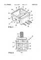
- FIG. 1is a perspective view, partially exploded, of a patellar resection guide of the present invention
- FIG. 2is a top view of the assembled patellar resection guide of FIG. 1;
- FIG. 3is an end view of the patellar resection guide of FIG. 1;
- FIG. 4is a side view of the patellar resection guide of FIG. 1;
- FIG. 5is a perspective view of a cradle of the patellar resection guide shown in FIGS. 1-4;
- FIG. 6is a perspective view of a modified cradle
- FIG. 7is a front end view of an embodiment of a bone guide plate of the patellar resection guide of FIG. 1 with a plurality of saw blade slots;
- FIG. 8is a front end view similar to FIG. 7 showing a bone guide plate with an alternate arrangement of saw blade slots;
- FIG. 9is a side view of a stop plate showing an adjustment bolt and guide rods
- FIG. 10is a side view of a captured adjustment nut employed in the patellar resection guide of FIG. 1;
- FIG. 11is a bottom view of a blade guide plate showing a T shaped channel to accommodate the removable captured nut shown in FIG. 10;
- FIG. 12is a front view of the stop plate of the patellar resection guide of FIG. 1;
- FIG. 13shows a diagrammatic side view of the patellar resection guide of FIG. 1 as used during a surgical procedure
- FIGS. 14 and 15are diagrammatic views showing steps in a surgical method using the resection guide of FIG. 1.
- a patellar resection guideis designated 10, and comprises a cradle 12 and a pair of gripping elements such as plates 14, 20.
- the cradle 12is used to suspend the patella in a desired orientation established by supporting posterior surfaces of the quadriceps tendon and patellar ligament between the surfaces of spaced, parallel first and second cradle supports 30, 31, locating the articular surface of the patella in a position where it can be accessed by the surgeon's bone saw blade for resection.
- the gripping platescomprise a blade guide plate 14 and a stop plate 20, both generally rectangular in shape and having patella gripping surfaces 21, 23.
- the gripping platesare sized and positioned to fit between the cradle supports 30, 31 to permit adjustable positioning of the distance between their respective gripping surfaces.
- the cradle supports 30, 31are joined by a body defined by cross members 29.
- An adjustment bolt 16passes through an aperture 36 in the cross members 29 of the cradle 12, as do two guide rods 17 arranged in parallel with the adjustment bolt 16.
- One or more saw blade slots 24are formed through the blade guide plate 14 at positions designed to represent the proper depth required for resecting the articular surface of the patella.
- Stop plate 20is positioned with its gripping surface 21 opposed to and confronting the gripping surface 23 of the guide plate 14, the surfaces 21 and 23 desirably being parallel. Adjustment bolt 16 passes through the apertures 36 in the cross members 29 of the cradle 12, and guide rods 17 pass snugly through the apertures 34 in the cross members 29 and through the apertures 35 in the blade guide plate 14 to allow for controlled, supportive convergent and divergent travel of the blade guide plate 14 and stop plate 20. Blade guide plate similarly possesses an aperture 33 sized to receive adjustment bolt 16. Stop plate 20 is of similar size and shape to the blade guide plate 14, but may or may not contain a slot for guiding a saw blade. Stop plate 20 may be shallower in depth than blade guide plate 14.
- Adjustment bolt 16 and guide rods 17are rigidly affixed to the stop plate 20. Adjustment bolt 16 is threaded from the portion extending from its free end to a point toward the stop plate 20 where the size limitations of the patella or cradle 12 obviate the need for further threading.
- the stop plate 20 and affixed adjustment bolt 16 and affixed guide rods 17are fitted through apertures 36, 34 in the cross members 29 forming the base of cradle 12, the blade guide plate 14 confront each other, as shown in FIG. 1.
- the blade guide plate 14has a T shaped channel 15 cut into its bottom side to receive a nut 19 that is threaded onto the adjustment bolt 16.
- the nutis restrained by the walls of the crossbar portion of the T channel from movement parallel to its axis, and includes a tubular portion exuding through the leg of the T and terminating in an external, preferably knurled handle 25.
- Manual rotation of the handle 25rotates the nut upon the threaded portion of the bolt to cause the blade guide plate 14 and stop plate 20 to be selectively moved toward and away from each other to accommodate and secure various sized patellae which may be encountered.
- the guide rods 17ensure parallel movement of the blade guide plate 14 and stop plate 20.
- the gripping surfaces 21, 23 of the blade guide plate 14 and stop plate 20may be provided with teeth 18, 22 or other irregular surfaces to facilitate grasping of the patella during the resection procedure.
- the supports 30, 31have at their distal ends angled end portions that define end stops 32, the latter preferably being substantially at right angles to the cradle supports 30, 31.
- the cradle supports 30, 31are connected in a substantially perpendicular manner to upright members 28.
- the upright members 28are connected at substantially right angles to cross members 29.
- Cradle 12is substantially symmetrical in configuration and serves as the framework for the other components of the invention.
- the patellar resection guide 10quickly disassembles for easy cleaning or replacement of components.
- Cradle 12is provided with apertures 34, 36 which are adapted so as to slidably receive the guide rods 17.
- Aperture 36is adapted to slidably receive adjustment bolt 16.
- Apertures 34, 36are sized to allow blade guide plate 14 and stop plate 20 to adjust the distance from each other which will occur with rotating the adjustment nut 16. Tolerances between apertures 34, 36 and the respective guide rods 17 and adjustment bolt 16 should be great enough to allow free movement, but close enough to prevent unnecessary looseness during the operation of the patellar resection guide and to maintain the plates in their parallel orientation as they are drawn together.
- the cradle supports 30, 31are on opposite ends of the cradle 12 and desirably are parallel to each other; that is, they have outer surfaces 48, 50 that are congruent to each other.
- Support surfaces 48, 50may be slightly curved (concave outwardly), but preferably are straight in the medial-lateral direction to define between them a reference plane. They are used to suspend the quadriceps tendon and patella ligament in a plane which is parallel to but not necessarily coplanar with the desired resection plane.
- the distance between cradle supports 30, 31is sufficient to accommodate between them a human patella with the posterior surfaces of the attached quadriceps tendon and patellar ligament resting on the cradle supports.
- the spacing between the cradle supportsis slightly greater than the superior-inferior dimension of the patella so that when the patella is drawn between the cradle supports as by flexing the knee, the supports do not contact the patella itself.
- the end-to-end dimension of the gripping platesis sufficiently small as to enable the plates to fit between cradle supports separated by varying distances.
- the resection guideis modular in construction so that a cradle of any particular chosen size can be assembled with a standard sized pair of gripping plates. Of course, if desired, gripping plates of varying dimensions can be supplied as well.
- FIG. 6shows an embodiment in which the frame structure supporting the cradles is itself adjustable to enable the cradles to move toward and away from each other while maintaining their mutually parallel orientation.
- each of the cradle cross members 29is formed with telescoping ends, one end 38 of each cross member being telescopingly received in the adjacent hollow end 40. Set screws 42 may be used to join the ends 38, 40 together once the correct length of these members has been set.
- the confronting surfaces 44, 46 of the respective cradle supports 30, 31may serve as gripping surfaces (and may be provided with teeth or the like) to grip between them a patella, the quadriceps tendon and patellar ligament of which rest against the outer support surfaces 48, 50 of the cradle supports.
- Saw blade guiding surfaces or slotsmay be provided to guide a saw blade.
- FIGS. 7 and 8show an embodiment of the blade guide plate 14 having a plurality of saw blade guide slots 24.
- the saw blade slots 24 as shownillustrate how the invention is able to accommodate various depths of resection the surgeon may require due to differing sized patellae or conditions.
- the blade guide plate 14must also provide stability and orientation to the oscillating saw blade to ensure that the resection is done in the proper plane. This is accomplished by employing a slot depth sufficient to prevent significant tilting of the saw blade during the resection procedure. Slot depth dimensions of approximately 0.25 inch to 0.5 inches have been shown to be adequate for this purpose. These dimensions, however, are intended to be illustrative and not limiting.
- the patellamay be resected by forming holes, grooves or other shapes in or on the posterior patellar surface.
- the end-to-end length of the blade guide plate 14 and stop plate 20are less than the distance between the cradle supports 30, 31 to enable blade guide plate 14 and stop plate 20 to move toward each other sufficiently close to effectively grasp the patella during the resection procedure. It is contemplated and within the scope of this invention to manufacture the cradle 12 in various sizes, to be able to accommodate differently sized patellae. Similarly, blade guide plate 14 and stop plate 20 would be sized to be able to be compatible with the contemplated variously sized cradles 12.
- FIG. 9shows the stop plate 20 with rigidly affixed guide rods 17 and adjustment bolt 16.
- FIG. 12shows the stop plate 20 and affixed adjustment bolt 16 and guide rods 17 prior to assembly.
- the preferred material for all components of this inventionis stainless steel.
- FIG. 13shows the patellar resection guide 10 as it would be used during an actual procedure. It can be seen that the quadriceps tendon T and patellar ligament L are suspended in a plane defined by first cradle support 30 and second cradle support 31 of the cradle 12. The patella P is secured in the patellar resection guide 10 by means of force exerted by the gripping surfaces 21, 23. Flexion of the knee joint causes the quadriceps tendon T and patellar ligament L to press against the cradle supports, properly orienting the patella between the gripping plates before they are moved to their gripping position. The procedure for using the guide is discussed in detail below.
- the surgeonfirst creates a longitudinal incision medial to the patella to expose the patella and quadriceps mechanism which includes the quadriceps tendon and patellar ligament. This is done to a degree allowing exposure of sufficient quadriceps tissue and patellar ligament to permit the surgeon to rotate the patella laterally prior to insertion of the resection guide 10.
- the patellais disarticulated from the femur and is turned upside down, that is, it is rotated laterally through about 180°, resulting in the articular surface A of the patella facing forward or anteriorly (that is, outwardly).
- the surgeonplaces the patellar resection guide 10 over the exposed articular surface of the patella, with the cradle supports adjacent the quadriceps tendon and patellar ligament.
- the patella and patellar resection guide togetherare re-rotated medially through about 180° to position the resection guide 10 between the patella and the femur.
- the kneeis slightly flexed to tension the quadriceps mechanism, thereby applying a compressive load between the patella and femur. This draws the quadriceps ligament and patella tendon firmly into the cradle supports of the guide 10.
- the patellar tendon and ligamentare firmly seated in the cradle 12, as shown in FIG.
- the patellais positioned in a repeatable or reference position with respect to the reference plane defined by the cradle support surfaces. This position is defined by the posterior aspect of the inferior and superior margins of the ligament and tendon attachment of the patella, respectively, which, when they are firmly seated against the support surfaces, lie in the reference plane defined by the cradle supports. This plane is typically perpendicular to the resultant forces acting on the patella and is parallel to the plane of the intended resection. The preferred orientation of the patellar resection plane is perpendicular to the resultant forces acting across the patellar femoral joint. While maintaining slight flexion on the knee, the captured nut 19 is rotated in a direction causing the blade guide plate 14 and stop plate 20 to move closer together. The blade guide plate 14 and stop plate 20 move in a mediolateral sense. This procedure is followed until the patella is securely gripped in the patellar resection guide 10.
- the patella and resection guideare again rotated laterally to again orient the resection guide 10 and articular surface of the patella outwardly, as shown in FIG. 15.
- the surgeonplaces an oscillating bone saw of a type commonly known into the saw blade slot 24 and advances the saw to resect the patella.
- the articular surface of the patellais resected at a level posterior to the ligament and tendon insertions. This permits the surgeon to resect only bone tissue, avoiding the ligaments and tendons.
- the depth of resection beneath the ligament and tendon insertion levelsmay vary depending on surgeon preference. In one embodiment the invention accommodates for this requirement by providing multiple saw blade slots 24 at differing levels in the blade guide plate 14. In one embodiment, a level of one millimeter is used. The level may range from a level matching that of the ligament and tendon insertion level, to a level posterior to it, or anterior to it.
- the patellar resection guide 10is removed. After removal of the guide 10, the surgeon will follow established procedures to further prepare the resected articular surface of the patella to accept a patellar button or other implant.
Landscapes
- Health & Medical Sciences (AREA)
- Life Sciences & Earth Sciences (AREA)
- Surgery (AREA)
- Dentistry (AREA)
- Biomedical Technology (AREA)
- Oral & Maxillofacial Surgery (AREA)
- Nuclear Medicine, Radiotherapy & Molecular Imaging (AREA)
- Physical Education & Sports Medicine (AREA)
- Orthopedic Medicine & Surgery (AREA)
- Engineering & Computer Science (AREA)
- Transplantation (AREA)
- Heart & Thoracic Surgery (AREA)
- Medical Informatics (AREA)
- Molecular Biology (AREA)
- Animal Behavior & Ethology (AREA)
- General Health & Medical Sciences (AREA)
- Public Health (AREA)
- Veterinary Medicine (AREA)
- Surgical Instruments (AREA)
Abstract
Description
Claims (29)
Priority Applications (1)
| Application Number | Priority Date | Filing Date | Title |
|---|---|---|---|
| US08/642,696US5667512A (en) | 1996-05-03 | 1996-05-03 | Patellar resection guide |
Applications Claiming Priority (1)
| Application Number | Priority Date | Filing Date | Title |
|---|---|---|---|
| US08/642,696US5667512A (en) | 1996-05-03 | 1996-05-03 | Patellar resection guide |
Publications (1)
| Publication Number | Publication Date |
|---|---|
| US5667512Atrue US5667512A (en) | 1997-09-16 |
Family
ID=24577641
Family Applications (1)
| Application Number | Title | Priority Date | Filing Date |
|---|---|---|---|
| US08/642,696Expired - Fee RelatedUS5667512A (en) | 1996-05-03 | 1996-05-03 | Patellar resection guide |
Country Status (1)
| Country | Link |
|---|---|
| US (1) | US5667512A (en) |
Cited By (74)
| Publication number | Priority date | Publication date | Assignee | Title |
|---|---|---|---|---|
| WO2000035359A1 (en)* | 1998-12-15 | 2000-06-22 | Waddell David D | In situ patellar resection guide |
| US20030176867A1 (en)* | 2002-03-12 | 2003-09-18 | Long Jack F. | Blade for resection of bone for prosthesis implantation, blade stop and method |
| US6702821B2 (en) | 2000-01-14 | 2004-03-09 | The Bonutti 2003 Trust A | Instrumentation for minimally invasive joint replacement and methods for using same |
| WO2004075767A1 (en)* | 2003-02-26 | 2004-09-10 | Aesculap Ag & Co. Kg | Patella-referencing device |
| US6855150B1 (en) | 2001-07-13 | 2005-02-15 | Timothy R. Linehan | Patellar trial and drill guide for use in knee replacement surgery |
| US20060161165A1 (en)* | 2002-05-10 | 2006-07-20 | Swanson Todd V | Patellar cutting guide |
| US7104996B2 (en) | 2000-01-14 | 2006-09-12 | Marctec. Llc | Method of performing surgery |
| GB2434747A (en)* | 2006-02-01 | 2007-08-08 | Biomet Uk Ltd | Surgical jig for the knee |
| US20070233142A1 (en)* | 2006-03-14 | 2007-10-04 | Oliver Ralph S | Apparatus and method for implementing patella resection guide during minimally invasive surgery |
| US20080114369A1 (en)* | 2006-11-14 | 2008-05-15 | Howmedica Osteonics Corp. | Adjustable resection guide |
| US20080306484A1 (en)* | 2003-02-03 | 2008-12-11 | Zimmer, Inc. | Apparatus for knee surgery and method of use |
| US7488324B1 (en) | 2003-12-08 | 2009-02-10 | Biomet Manufacturing Corporation | Femoral guide for implanting a femoral knee prosthesis |
| US7510557B1 (en) | 2000-01-14 | 2009-03-31 | Bonutti Research Inc. | Cutting guide |
| US7566335B1 (en) | 2004-11-22 | 2009-07-28 | Biomet Manufacturing Corp. | Method and apparatus for patella resection |
| US7695520B2 (en) | 2006-05-31 | 2010-04-13 | Biomet Manufacturing Corp. | Prosthesis and implementation system |
| US7695479B1 (en) | 2005-04-12 | 2010-04-13 | Biomet Manufacturing Corp. | Femoral sizer |
| US7708741B1 (en) | 2001-08-28 | 2010-05-04 | Marctec, Llc | Method of preparing bones for knee replacement surgery |
| US7780672B2 (en) | 2006-02-27 | 2010-08-24 | Biomet Manufacturing Corp. | Femoral adjustment device and associated method |
| US7789885B2 (en) | 2003-01-15 | 2010-09-07 | Biomet Manufacturing Corp. | Instrumentation for knee resection |
| US7799084B2 (en) | 2002-10-23 | 2010-09-21 | Mako Surgical Corp. | Modular femoral component for a total knee joint replacement for minimally invasive implantation |
| US7837690B2 (en) | 2003-01-15 | 2010-11-23 | Biomet Manufacturing Corp. | Method and apparatus for less invasive knee resection |
| US7887542B2 (en) | 2003-01-15 | 2011-02-15 | Biomet Manufacturing Corp. | Method and apparatus for less invasive knee resection |
| US8070752B2 (en) | 2006-02-27 | 2011-12-06 | Biomet Manufacturing Corp. | Patient specific alignment guide and inter-operative adjustment |
| US8152846B2 (en)* | 2008-03-06 | 2012-04-10 | Musculoskeletal Transplant Foundation | Instrumentation and method for repair of meniscus tissue |
| USD666721S1 (en) | 2011-06-30 | 2012-09-04 | Depuy Products, Inc. | Patella resection guide |
| USD666720S1 (en) | 2011-06-30 | 2012-09-04 | Depuy Products, Inc. | Patella resection guide |
| US8265949B2 (en) | 2007-09-27 | 2012-09-11 | Depuy Products, Inc. | Customized patient surgical plan |
| USD667110S1 (en) | 2011-06-30 | 2012-09-11 | Depuy Products, Inc. | Multifunctional handle |
| USD667953S1 (en) | 2011-06-30 | 2012-09-25 | Depuy Products, Inc. | Combination patella drill guide and clamp |
| US8343159B2 (en) | 2007-09-30 | 2013-01-01 | Depuy Products, Inc. | Orthopaedic bone saw and method of use thereof |
| US8357111B2 (en) | 2007-09-30 | 2013-01-22 | Depuy Products, Inc. | Method and system for designing patient-specific orthopaedic surgical instruments |
| US20130035693A1 (en)* | 2011-06-30 | 2013-02-07 | Wright Abraham P | Patella resection guide with locating features and method of using the same |
| USD679395S1 (en) | 2011-06-30 | 2013-04-02 | Depuy (Ireland) | Combination patella clamp and drill guide |
| US8551100B2 (en) | 2003-01-15 | 2013-10-08 | Biomet Manufacturing, Llc | Instrumentation for knee resection |
| US8747410B2 (en) | 2010-10-26 | 2014-06-10 | Zimmer, Inc. | Patellar resection instrument with variable depth guide |
| US8821501B2 (en) | 2010-09-24 | 2014-09-02 | Depuy (Ireland) | Patella resectioning guide and assembly |
| US8915923B2 (en) | 2011-09-28 | 2014-12-23 | Depuy (Ireland) | Patella resection assembly |
| US8951262B2 (en) | 2011-06-30 | 2015-02-10 | Depuy (Ireland) | Patella clamp and drill guide surgical instrument |
| US8979854B2 (en) | 2011-06-30 | 2015-03-17 | Depuy (Ireland) | Patella orthopaedic surgical instrument assembly |
| US8986306B2 (en) | 2011-06-30 | 2015-03-24 | Depuy (Ireland) | Patella orthopaedic surgical method |
| US8998912B2 (en) | 2011-09-28 | 2015-04-07 | Depuy (Ireland) | Clamping patella drill guide |
| US8998913B2 (en) | 2011-09-28 | 2015-04-07 | Depuy (Ireland) | Patella resection assembly |
| US9078676B2 (en) | 2011-09-28 | 2015-07-14 | Depuy (Ireland) | Patella drilling system |
| US9078772B2 (en) | 2011-09-28 | 2015-07-14 | Depuy (Ireland) | Rotatable patella drill guide |
| US20150297361A1 (en)* | 2014-04-18 | 2015-10-22 | Biomet Manufacturing, Llc | Orthopaedic instrument for securing a bone |
| WO2017002085A1 (en)* | 2015-07-02 | 2017-01-05 | University Of Cape Town | Accessory for conducting patella surgery |
| US9554813B2 (en) | 2012-09-28 | 2017-01-31 | Depuy Ireland Unlimited Company | Patella drill guide and trial surgical instrument |
| CN106618678A (en)* | 2017-01-24 | 2017-05-10 | 丽水市人民医院 | Infrapatellar fat pad excision device |
| CN106725744A (en)* | 2017-01-24 | 2017-05-31 | 丽水市人民医院 | A kind of subpatellar fat pad resectoscope and its application method |
| US9700329B2 (en) | 2006-02-27 | 2017-07-11 | Biomet Manufacturing, Llc | Patient-specific orthopedic instruments |
| US9743935B2 (en) | 2011-03-07 | 2017-08-29 | Biomet Manufacturing, Llc | Patient-specific femoral version guide |
| US9795399B2 (en) | 2006-06-09 | 2017-10-24 | Biomet Manufacturing, Llc | Patient-specific knee alignment guide and associated method |
| US9913734B2 (en) | 2006-02-27 | 2018-03-13 | Biomet Manufacturing, Llc | Patient-specific acetabular alignment guides |
| US9968376B2 (en) | 2010-11-29 | 2018-05-15 | Biomet Manufacturing, Llc | Patient-specific orthopedic instruments |
| CN108524015A (en)* | 2018-02-12 | 2018-09-14 | 沈阳尚贤健康科学技术股份有限公司 | A kind of bone clamping device |
| US10085758B2 (en) | 2012-09-28 | 2018-10-02 | Depuy Ireland Unlimited Company | Patella drill guide and trial surgical instrument having an alignment bore formed therein and method of using the same |
| US10159498B2 (en) | 2008-04-16 | 2018-12-25 | Biomet Manufacturing, Llc | Method and apparatus for manufacturing an implant |
| US10206695B2 (en) | 2006-02-27 | 2019-02-19 | Biomet Manufacturing, Llc | Femoral acetabular impingement guide |
| US10278714B2 (en) | 2015-03-27 | 2019-05-07 | Depuy Ireland Unlimted Company | Orthopaedic surgical instrument system for implanting a prosthetic patella component and method of use |
| US10278711B2 (en) | 2006-02-27 | 2019-05-07 | Biomet Manufacturing, Llc | Patient-specific femoral guide |
| US10335163B2 (en) | 2013-03-05 | 2019-07-02 | Depuy Ireland Unlimited Company | Polymer 4-in-2 femoral cutting instrument having separable A/P and chamfer cutting blocks |
| US10390845B2 (en) | 2006-02-27 | 2019-08-27 | Biomet Manufacturing, Llc | Patient-specific shoulder guide |
| US10426492B2 (en) | 2006-02-27 | 2019-10-01 | Biomet Manufacturing, Llc | Patient specific alignment guide with cutting surface and laser indicator |
| US10507029B2 (en) | 2006-02-27 | 2019-12-17 | Biomet Manufacturing, Llc | Patient-specific acetabular guides and associated instruments |
| US10603179B2 (en) | 2006-02-27 | 2020-03-31 | Biomet Manufacturing, Llc | Patient-specific augments |
| US10722310B2 (en) | 2017-03-13 | 2020-07-28 | Zimmer Biomet CMF and Thoracic, LLC | Virtual surgery planning system and method |
| US10743937B2 (en) | 2006-02-27 | 2020-08-18 | Biomet Manufacturing, Llc | Backup surgical instrument system and method |
| US20210068967A1 (en)* | 2019-09-10 | 2021-03-11 | Depuy Ireland Unlimited Company | Orthopaedic knee prosthesis system and methods for using same |
| US11051829B2 (en) | 2018-06-26 | 2021-07-06 | DePuy Synthes Products, Inc. | Customized patient-specific orthopaedic surgical instrument |
| US11534313B2 (en) | 2006-02-27 | 2022-12-27 | Biomet Manufacturing, Llc | Patient-specific pre-operative planning |
| US11554019B2 (en) | 2007-04-17 | 2023-01-17 | Biomet Manufacturing, Llc | Method and apparatus for manufacturing an implant |
| US12076025B2 (en) | 2022-05-11 | 2024-09-03 | DePuy Synthes Products, Inc. | Polymer cutting block |
| US12279960B2 (en) | 2020-07-10 | 2025-04-22 | Depuy Ireland Unlimited Company | Medial stabilized orthopaedic tibial insert |
| US12419753B2 (en) | 2019-03-12 | 2025-09-23 | Depuy Ireland Unlimited Company | Orthopaedic system with medial pivoting femoral component and insert |
Citations (15)
| Publication number | Priority date | Publication date | Assignee | Title |
|---|---|---|---|---|
| US4335715A (en)* | 1980-06-20 | 1982-06-22 | Kirkley William H | Osteotomy guide |
| US4349018A (en)* | 1980-12-29 | 1982-09-14 | Chambers Gary R | Osteotomy apparatus |
| US4421112A (en)* | 1982-05-20 | 1983-12-20 | Minnesota Mining And Manufacturing Company | Tibial osteotomy guide assembly and method |
| US4565191A (en)* | 1984-01-12 | 1986-01-21 | Slocum D Barclay | Apparatus and method for performing cuneiform osteotomy |
| US4633862A (en)* | 1985-05-30 | 1987-01-06 | Petersen Thomas D | Patellar resection sawguide |
| US4706660A (en)* | 1985-05-30 | 1987-11-17 | Petersen Thomas D | Patellar clamp |
| US4757810A (en)* | 1986-07-23 | 1988-07-19 | Reese Hewitt W | Osteotomy apparatus and method |
| US5002547A (en)* | 1987-02-07 | 1991-03-26 | Pfizer Hospital Products Group, Inc. | Apparatus for knee prosthesis |
| US5021056A (en)* | 1989-09-14 | 1991-06-04 | Intermedics Orthopedics, Inc. | Upper tibial osteotomy system |
| US5053039A (en)* | 1989-09-14 | 1991-10-01 | Intermedics Orthopedics | Upper tibial osteotomy system |
| US5108401A (en)* | 1991-04-12 | 1992-04-28 | New York Society For The Relief Of The Ruptured And Crippled, Maintaining The Hospital For Special Surgery | Patella cutting clamp |
| US5116338A (en)* | 1988-02-03 | 1992-05-26 | Pfizer Hospital Products Group, Inc. | Apparatus for knee prosthesis |
| US5246444A (en)* | 1990-01-08 | 1993-09-21 | Schreiber Saul N | Osteotomy device and method |
| US5486177A (en)* | 1994-12-20 | 1996-01-23 | Intermedics Orthopedics, Inc. | Patella planer with adjustable stop |
| US5542947A (en)* | 1995-05-12 | 1996-08-06 | Huwmedica Inc. | Slotted patella resection guide and stylus |
- 1996
- 1996-05-03USUS08/642,696patent/US5667512A/ennot_activeExpired - Fee Related
Patent Citations (15)
| Publication number | Priority date | Publication date | Assignee | Title |
|---|---|---|---|---|
| US4335715A (en)* | 1980-06-20 | 1982-06-22 | Kirkley William H | Osteotomy guide |
| US4349018A (en)* | 1980-12-29 | 1982-09-14 | Chambers Gary R | Osteotomy apparatus |
| US4421112A (en)* | 1982-05-20 | 1983-12-20 | Minnesota Mining And Manufacturing Company | Tibial osteotomy guide assembly and method |
| US4565191A (en)* | 1984-01-12 | 1986-01-21 | Slocum D Barclay | Apparatus and method for performing cuneiform osteotomy |
| US4633862A (en)* | 1985-05-30 | 1987-01-06 | Petersen Thomas D | Patellar resection sawguide |
| US4706660A (en)* | 1985-05-30 | 1987-11-17 | Petersen Thomas D | Patellar clamp |
| US4757810A (en)* | 1986-07-23 | 1988-07-19 | Reese Hewitt W | Osteotomy apparatus and method |
| US5002547A (en)* | 1987-02-07 | 1991-03-26 | Pfizer Hospital Products Group, Inc. | Apparatus for knee prosthesis |
| US5116338A (en)* | 1988-02-03 | 1992-05-26 | Pfizer Hospital Products Group, Inc. | Apparatus for knee prosthesis |
| US5021056A (en)* | 1989-09-14 | 1991-06-04 | Intermedics Orthopedics, Inc. | Upper tibial osteotomy system |
| US5053039A (en)* | 1989-09-14 | 1991-10-01 | Intermedics Orthopedics | Upper tibial osteotomy system |
| US5246444A (en)* | 1990-01-08 | 1993-09-21 | Schreiber Saul N | Osteotomy device and method |
| US5108401A (en)* | 1991-04-12 | 1992-04-28 | New York Society For The Relief Of The Ruptured And Crippled, Maintaining The Hospital For Special Surgery | Patella cutting clamp |
| US5486177A (en)* | 1994-12-20 | 1996-01-23 | Intermedics Orthopedics, Inc. | Patella planer with adjustable stop |
| US5542947A (en)* | 1995-05-12 | 1996-08-06 | Huwmedica Inc. | Slotted patella resection guide and stylus |
Cited By (151)
| Publication number | Priority date | Publication date | Assignee | Title |
|---|---|---|---|---|
| WO2000035359A1 (en)* | 1998-12-15 | 2000-06-22 | Waddell David D | In situ patellar resection guide |
| US6174314B1 (en)* | 1998-12-15 | 2001-01-16 | David D. Waddell | In situ pattellar resection guide |
| US9101443B2 (en) | 2000-01-14 | 2015-08-11 | Bonutti Skeletal Innovations Llc | Methods for robotic arthroplasty |
| US9192459B2 (en) | 2000-01-14 | 2015-11-24 | Bonutti Skeletal Innovations Llc | Method of performing total knee arthroplasty |
| US8425522B2 (en) | 2000-01-14 | 2013-04-23 | Bonutti Skeletal Innovations Llc | Joint replacement method |
| US7892236B1 (en) | 2000-01-14 | 2011-02-22 | Marctec, Llc | System and method for total joint replacement |
| US9795394B2 (en) | 2000-01-14 | 2017-10-24 | Bonutti Skeletal Innovations Llc | Method for placing implant using robotic system |
| US7959635B1 (en) | 2000-01-14 | 2011-06-14 | Marctec, Llc. | Limited incision total joint replacement methods |
| US8632552B2 (en) | 2000-01-14 | 2014-01-21 | Bonutti Skeletal Innovations Llc | Method of preparing a femur and tibia in knee arthroplasty |
| US7104996B2 (en) | 2000-01-14 | 2006-09-12 | Marctec. Llc | Method of performing surgery |
| US7828852B2 (en) | 2000-01-14 | 2010-11-09 | Marctec, Llc. | Inlaid articular implant |
| US7635390B1 (en) | 2000-01-14 | 2009-12-22 | Marctec, Llc | Joint replacement component having a modular articulating surface |
| US8784495B2 (en) | 2000-01-14 | 2014-07-22 | Bonutti Skeletal Innovations Llc | Segmental knee arthroplasty |
| US6702821B2 (en) | 2000-01-14 | 2004-03-09 | The Bonutti 2003 Trust A | Instrumentation for minimally invasive joint replacement and methods for using same |
| US7806896B1 (en) | 2000-01-14 | 2010-10-05 | Marctec, Llc | Knee arthroplasty method |
| US8133229B1 (en) | 2000-01-14 | 2012-03-13 | Marctec, Llc. | Knee arthroplasty method |
| US7510557B1 (en) | 2000-01-14 | 2009-03-31 | Bonutti Research Inc. | Cutting guide |
| US7931690B1 (en) | 2000-01-14 | 2011-04-26 | Marctec, Llc | Method of resurfacing an articular surface of a bone |
| US7806897B1 (en) | 2000-01-14 | 2010-10-05 | Marctec, Llc | Knee arthroplasty and preservation of the quadriceps mechanism |
| US7615054B1 (en) | 2000-01-14 | 2009-11-10 | Martec, LLC | Bicompartmental knee implant and method |
| US7837736B2 (en) | 2000-01-14 | 2010-11-23 | Marctec, Llc | Minimally invasive surgical systems and methods |
| US7749229B1 (en) | 2000-01-14 | 2010-07-06 | Marctec, Llc | Total knee arthroplasty through shortened incision |
| US7708740B1 (en) | 2000-01-14 | 2010-05-04 | Marctec, Llc | Method for total knee arthroplasty and resecting bone in situ |
| US6855150B1 (en) | 2001-07-13 | 2005-02-15 | Timothy R. Linehan | Patellar trial and drill guide for use in knee replacement surgery |
| US10470780B2 (en) | 2001-08-28 | 2019-11-12 | Bonutti Skeletal Innovations Llc | Systems and methods for ligament balancing in robotic surgery |
| US10231739B1 (en) | 2001-08-28 | 2019-03-19 | Bonutti Skeletal Innovations Llc | System and method for robotic surgery |
| US8858557B2 (en) | 2001-08-28 | 2014-10-14 | Bonutti Skeletal Innovations Llc | Method of preparing a femur and tibia in knee arthroplasty |
| US8840629B2 (en) | 2001-08-28 | 2014-09-23 | Bonutti Skeletal Innovations Llc | Robotic arthroplasty system including navigation |
| US8834490B2 (en) | 2001-08-28 | 2014-09-16 | Bonutti Skeletal Innovations Llc | Method for robotic arthroplasty using navigation |
| US10321918B2 (en) | 2001-08-28 | 2019-06-18 | Bonutti Skeletal Innovations Llc | Methods for robotic surgery using a cannula |
| US9763683B2 (en) | 2001-08-28 | 2017-09-19 | Bonutti Skeletal Innovations Llc | Method for performing surgical procedures using optical cutting guides |
| US9060797B2 (en) | 2001-08-28 | 2015-06-23 | Bonutti Skeletal Innovations Llc | Method of preparing a femur and tibia in knee arthroplasty |
| US8641726B2 (en) | 2001-08-28 | 2014-02-04 | Bonutti Skeletal Innovations Llc | Method for robotic arthroplasty using navigation |
| US8623030B2 (en) | 2001-08-28 | 2014-01-07 | Bonutti Skeletal Innovations Llc | Robotic arthroplasty system including navigation |
| US7708741B1 (en) | 2001-08-28 | 2010-05-04 | Marctec, Llc | Method of preparing bones for knee replacement surgery |
| US20030176867A1 (en)* | 2002-03-12 | 2003-09-18 | Long Jack F. | Blade for resection of bone for prosthesis implantation, blade stop and method |
| US6875222B2 (en) | 2002-03-12 | 2005-04-05 | Depuy Products, Inc. | Blade for resection of bone for prosthesis implantation, blade stop and method |
| US7604639B2 (en)* | 2002-05-10 | 2009-10-20 | Smith & Nephew, Inc. | Patellar cutting guide |
| US20060161165A1 (en)* | 2002-05-10 | 2006-07-20 | Swanson Todd V | Patellar cutting guide |
| US7799084B2 (en) | 2002-10-23 | 2010-09-21 | Mako Surgical Corp. | Modular femoral component for a total knee joint replacement for minimally invasive implantation |
| US9023053B2 (en) | 2003-01-15 | 2015-05-05 | Biomet Manufacturing, Llc | Instrumentation for knee resection |
| US8870883B2 (en) | 2003-01-15 | 2014-10-28 | Biomet Manufacturing, Llc | Method for less invasive knee resection |
| US8551100B2 (en) | 2003-01-15 | 2013-10-08 | Biomet Manufacturing, Llc | Instrumentation for knee resection |
| US7837690B2 (en) | 2003-01-15 | 2010-11-23 | Biomet Manufacturing Corp. | Method and apparatus for less invasive knee resection |
| US9693788B2 (en) | 2003-01-15 | 2017-07-04 | Biomet Manufacturing, Llc | Instrumentation for knee resection |
| US7789885B2 (en) | 2003-01-15 | 2010-09-07 | Biomet Manufacturing Corp. | Instrumentation for knee resection |
| US8518047B2 (en) | 2003-01-15 | 2013-08-27 | Biomet Manufacturing, Llc | Method and apparatus for less invasive knee resection |
| US7887542B2 (en) | 2003-01-15 | 2011-02-15 | Biomet Manufacturing Corp. | Method and apparatus for less invasive knee resection |
| US8118811B2 (en) | 2003-02-03 | 2012-02-21 | Zimmer, Inc. | Apparatus for knee surgery and method of use |
| US20080306484A1 (en)* | 2003-02-03 | 2008-12-11 | Zimmer, Inc. | Apparatus for knee surgery and method of use |
| US20060052792A1 (en)* | 2003-02-26 | 2006-03-09 | Aesculap Ag & Co. Kg | Patella reference device |
| WO2004075767A1 (en)* | 2003-02-26 | 2004-09-10 | Aesculap Ag & Co. Kg | Patella-referencing device |
| US7488324B1 (en) | 2003-12-08 | 2009-02-10 | Biomet Manufacturing Corporation | Femoral guide for implanting a femoral knee prosthesis |
| US8834486B2 (en) | 2003-12-08 | 2014-09-16 | Biomet Manufacturing, Llc | Femoral guide for implanting a femoral knee prosthesis |
| US8123758B2 (en) | 2003-12-08 | 2012-02-28 | Biomet Manufacturing Corp. | Femoral guide for implanting a femoral knee prosthesis |
| US7566335B1 (en) | 2004-11-22 | 2009-07-28 | Biomet Manufacturing Corp. | Method and apparatus for patella resection |
| US7695479B1 (en) | 2005-04-12 | 2010-04-13 | Biomet Manufacturing Corp. | Femoral sizer |
| US20070233139A1 (en)* | 2006-02-01 | 2007-10-04 | Metcalfe Nick J T | Surgical Jig |
| GB2434747A (en)* | 2006-02-01 | 2007-08-08 | Biomet Uk Ltd | Surgical jig for the knee |
| GB2434747B (en)* | 2006-02-01 | 2010-12-22 | Biomet Uk Ltd | Surgical jig for a knee |
| US10206695B2 (en) | 2006-02-27 | 2019-02-19 | Biomet Manufacturing, Llc | Femoral acetabular impingement guide |
| US10390845B2 (en) | 2006-02-27 | 2019-08-27 | Biomet Manufacturing, Llc | Patient-specific shoulder guide |
| US10603179B2 (en) | 2006-02-27 | 2020-03-31 | Biomet Manufacturing, Llc | Patient-specific augments |
| US8070752B2 (en) | 2006-02-27 | 2011-12-06 | Biomet Manufacturing Corp. | Patient specific alignment guide and inter-operative adjustment |
| US10743937B2 (en) | 2006-02-27 | 2020-08-18 | Biomet Manufacturing, Llc | Backup surgical instrument system and method |
| US9913734B2 (en) | 2006-02-27 | 2018-03-13 | Biomet Manufacturing, Llc | Patient-specific acetabular alignment guides |
| US9700329B2 (en) | 2006-02-27 | 2017-07-11 | Biomet Manufacturing, Llc | Patient-specific orthopedic instruments |
| US10426492B2 (en) | 2006-02-27 | 2019-10-01 | Biomet Manufacturing, Llc | Patient specific alignment guide with cutting surface and laser indicator |
| US7780672B2 (en) | 2006-02-27 | 2010-08-24 | Biomet Manufacturing Corp. | Femoral adjustment device and associated method |
| US10507029B2 (en) | 2006-02-27 | 2019-12-17 | Biomet Manufacturing, Llc | Patient-specific acetabular guides and associated instruments |
| US10278711B2 (en) | 2006-02-27 | 2019-05-07 | Biomet Manufacturing, Llc | Patient-specific femoral guide |
| US11534313B2 (en) | 2006-02-27 | 2022-12-27 | Biomet Manufacturing, Llc | Patient-specific pre-operative planning |
| US8182488B2 (en) | 2006-03-14 | 2012-05-22 | Ralph Scott Oliver | Apparatus and method for implementing patella resection guide during minimally invasive surgery |
| US20070233142A1 (en)* | 2006-03-14 | 2007-10-04 | Oliver Ralph S | Apparatus and method for implementing patella resection guide during minimally invasive surgery |
| US7695520B2 (en) | 2006-05-31 | 2010-04-13 | Biomet Manufacturing Corp. | Prosthesis and implementation system |
| US11576689B2 (en) | 2006-06-09 | 2023-02-14 | Biomet Manufacturing, Llc | Patient-specific knee alignment guide and associated method |
| US9795399B2 (en) | 2006-06-09 | 2017-10-24 | Biomet Manufacturing, Llc | Patient-specific knee alignment guide and associated method |
| US10206697B2 (en) | 2006-06-09 | 2019-02-19 | Biomet Manufacturing, Llc | Patient-specific knee alignment guide and associated method |
| US10893879B2 (en) | 2006-06-09 | 2021-01-19 | Biomet Manufacturing, Llc | Patient-specific knee alignment guide and associated method |
| US20080114369A1 (en)* | 2006-11-14 | 2008-05-15 | Howmedica Osteonics Corp. | Adjustable resection guide |
| US7938833B2 (en) | 2006-11-14 | 2011-05-10 | Howmedica Osteonics Corp. | Adjustable resection guide |
| US11554019B2 (en) | 2007-04-17 | 2023-01-17 | Biomet Manufacturing, Llc | Method and apparatus for manufacturing an implant |
| US8265949B2 (en) | 2007-09-27 | 2012-09-11 | Depuy Products, Inc. | Customized patient surgical plan |
| US12070231B2 (en) | 2007-09-27 | 2024-08-27 | DePuy Synthes Products, Inc. | Customized patient surgical plan |
| US11931049B2 (en) | 2007-09-30 | 2024-03-19 | DePuy Synthes Products, Inc. | Apparatus and method for fabricating a customized patient-specific orthopaedic instrument |
| US10028750B2 (en) | 2007-09-30 | 2018-07-24 | DePuy Synthes Products, Inc. | Apparatus and method for fabricating a customized patient-specific orthopaedic instrument |
| US8398645B2 (en) | 2007-09-30 | 2013-03-19 | DePuy Synthes Products, LLC | Femoral tibial customized patient-specific orthopaedic surgical instrumentation |
| US8377068B2 (en) | 2007-09-30 | 2013-02-19 | DePuy Synthes Products, LLC. | Customized patient-specific instrumentation for use in orthopaedic surgical procedures |
| US10828046B2 (en) | 2007-09-30 | 2020-11-10 | DePuy Synthes Products, Inc. | Apparatus and method for fabricating a customized patient-specific orthopaedic instrument |
| US11696768B2 (en) | 2007-09-30 | 2023-07-11 | DePuy Synthes Products, Inc. | Apparatus and method for fabricating a customized patient-specific orthopaedic instrument |
| US8343159B2 (en) | 2007-09-30 | 2013-01-01 | Depuy Products, Inc. | Orthopaedic bone saw and method of use thereof |
| US8357111B2 (en) | 2007-09-30 | 2013-01-22 | Depuy Products, Inc. | Method and system for designing patient-specific orthopaedic surgical instruments |
| US8357166B2 (en) | 2007-09-30 | 2013-01-22 | Depuy Products, Inc. | Customized patient-specific instrumentation and method for performing a bone re-cut |
| US8361076B2 (en) | 2007-09-30 | 2013-01-29 | Depuy Products, Inc. | Patient-customizable device and system for performing an orthopaedic surgical procedure |
| US8152846B2 (en)* | 2008-03-06 | 2012-04-10 | Musculoskeletal Transplant Foundation | Instrumentation and method for repair of meniscus tissue |
| US10159498B2 (en) | 2008-04-16 | 2018-12-25 | Biomet Manufacturing, Llc | Method and apparatus for manufacturing an implant |
| US11324522B2 (en) | 2009-10-01 | 2022-05-10 | Biomet Manufacturing, Llc | Patient specific alignment guide with cutting surface and laser indicator |
| US10893876B2 (en) | 2010-03-05 | 2021-01-19 | Biomet Manufacturing, Llc | Method and apparatus for manufacturing an implant |
| US8821501B2 (en) | 2010-09-24 | 2014-09-02 | Depuy (Ireland) | Patella resectioning guide and assembly |
| US8747410B2 (en) | 2010-10-26 | 2014-06-10 | Zimmer, Inc. | Patellar resection instrument with variable depth guide |
| US11234719B2 (en) | 2010-11-03 | 2022-02-01 | Biomet Manufacturing, Llc | Patient-specific shoulder guide |
| US9968376B2 (en) | 2010-11-29 | 2018-05-15 | Biomet Manufacturing, Llc | Patient-specific orthopedic instruments |
| US9743935B2 (en) | 2011-03-07 | 2017-08-29 | Biomet Manufacturing, Llc | Patient-specific femoral version guide |
| US9414851B2 (en) | 2011-06-30 | 2016-08-16 | Depuy (Ireland) | Patella clamp and drill guide surgical instrument and method of use |
| USD679395S1 (en) | 2011-06-30 | 2013-04-02 | Depuy (Ireland) | Combination patella clamp and drill guide |
| US20130035693A1 (en)* | 2011-06-30 | 2013-02-07 | Wright Abraham P | Patella resection guide with locating features and method of using the same |
| USD667953S1 (en) | 2011-06-30 | 2012-09-25 | Depuy Products, Inc. | Combination patella drill guide and clamp |
| USD667110S1 (en) | 2011-06-30 | 2012-09-11 | Depuy Products, Inc. | Multifunctional handle |
| US8951262B2 (en) | 2011-06-30 | 2015-02-10 | Depuy (Ireland) | Patella clamp and drill guide surgical instrument |
| US8968321B2 (en)* | 2011-06-30 | 2015-03-03 | Depuy (Ireland) | Patella resection guide with locating features and method of using the same |
| US8979854B2 (en) | 2011-06-30 | 2015-03-17 | Depuy (Ireland) | Patella orthopaedic surgical instrument assembly |
| US8986306B2 (en) | 2011-06-30 | 2015-03-24 | Depuy (Ireland) | Patella orthopaedic surgical method |
| USD666720S1 (en) | 2011-06-30 | 2012-09-04 | Depuy Products, Inc. | Patella resection guide |
| USD666721S1 (en) | 2011-06-30 | 2012-09-04 | Depuy Products, Inc. | Patella resection guide |
| US8998913B2 (en) | 2011-09-28 | 2015-04-07 | Depuy (Ireland) | Patella resection assembly |
| US8915923B2 (en) | 2011-09-28 | 2014-12-23 | Depuy (Ireland) | Patella resection assembly |
| US8998912B2 (en) | 2011-09-28 | 2015-04-07 | Depuy (Ireland) | Clamping patella drill guide |
| US9078676B2 (en) | 2011-09-28 | 2015-07-14 | Depuy (Ireland) | Patella drilling system |
| US9295483B2 (en) | 2011-09-28 | 2016-03-29 | Depuy (Ireland) | Rotatable patella drill guide |
| US9078772B2 (en) | 2011-09-28 | 2015-07-14 | Depuy (Ireland) | Rotatable patella drill guide |
| US11925365B2 (en) | 2012-09-28 | 2024-03-12 | Depuy Ireland Unlimited Company | Patella drill guide and trial surgical instrument |
| US11109873B2 (en) | 2012-09-28 | 2021-09-07 | Depuy Ireland Unlimited Company | Patella drill guide and trial surgical instrument system and method of using the same |
| US10085758B2 (en) | 2012-09-28 | 2018-10-02 | Depuy Ireland Unlimited Company | Patella drill guide and trial surgical instrument having an alignment bore formed therein and method of using the same |
| US9554813B2 (en) | 2012-09-28 | 2017-01-31 | Depuy Ireland Unlimited Company | Patella drill guide and trial surgical instrument |
| US9855065B2 (en) | 2012-09-28 | 2018-01-02 | Depuy Ireland Unlimited Company | Orthopaedic surgical instrument assembly for implanting a prosthetic patella component |
| US9700330B2 (en) | 2012-09-28 | 2017-07-11 | Depuy Ireland Unlimited Company | Method for surgically implanting a prosthetic patella component |
| US10335163B2 (en) | 2013-03-05 | 2019-07-02 | Depuy Ireland Unlimited Company | Polymer 4-in-2 femoral cutting instrument having separable A/P and chamfer cutting blocks |
| US11234711B2 (en) | 2013-03-05 | 2022-02-01 | Depuy Ireland Unlimited Company | Polymer 4-in-2 femoral cutting instrument having separable A/P and chamfer cutting blocks |
| US20150297361A1 (en)* | 2014-04-18 | 2015-10-22 | Biomet Manufacturing, Llc | Orthopaedic instrument for securing a bone |
| US9700438B2 (en)* | 2014-04-18 | 2017-07-11 | Biomet Manufacturing, Llc | Orthopaedic instrument for securing a bone |
| US11304711B2 (en) | 2015-03-27 | 2022-04-19 | Depuy Ireland Unlimited Company | Orthopaedic surgical instrument system for implanting a prosthetic patella component and method of use |
| US12167862B2 (en) | 2015-03-27 | 2024-12-17 | Depuy Ireland Unlimited Company | Orthopaedic surgical instrument system for implanting a prosthetic patella component and method of use |
| US12156663B2 (en) | 2015-03-27 | 2024-12-03 | Depuy Ireland Unlimited Company | Orthopaedic surgical instrument system for implanting a prosthetic patella component and method of use |
| US10278714B2 (en) | 2015-03-27 | 2019-05-07 | Depuy Ireland Unlimted Company | Orthopaedic surgical instrument system for implanting a prosthetic patella component and method of use |
| CN108366802A (en)* | 2015-07-02 | 2018-08-03 | 开普敦大学 | Assistive devices for performing patella surgery |
| WO2017002085A1 (en)* | 2015-07-02 | 2017-01-05 | University Of Cape Town | Accessory for conducting patella surgery |
| US10524807B2 (en) | 2015-07-02 | 2020-01-07 | Sarthak Patnaik | Accessory for conducting patella surgery |
| GB2540136A (en)* | 2015-07-02 | 2017-01-11 | Univ Cape Town | Accessory for conducting patella surgery |
| CN106725744A (en)* | 2017-01-24 | 2017-05-31 | 丽水市人民医院 | A kind of subpatellar fat pad resectoscope and its application method |
| CN106618678A (en)* | 2017-01-24 | 2017-05-10 | 丽水市人民医院 | Infrapatellar fat pad excision device |
| CN106725744B (en)* | 2017-01-24 | 2023-11-10 | 丽水市人民医院 | Infrapatellar fat pad resection device and method of use thereof |
| CN106618678B (en)* | 2017-01-24 | 2023-11-10 | 丽水市人民医院 | An infrapatellar fat pad resection device |
| US10722310B2 (en) | 2017-03-13 | 2020-07-28 | Zimmer Biomet CMF and Thoracic, LLC | Virtual surgery planning system and method |
| CN108524015A (en)* | 2018-02-12 | 2018-09-14 | 沈阳尚贤健康科学技术股份有限公司 | A kind of bone clamping device |
| US11950786B2 (en) | 2018-06-26 | 2024-04-09 | DePuy Synthes Products, Inc. | Customized patient-specific orthopaedic surgical instrument |
| US11051829B2 (en) | 2018-06-26 | 2021-07-06 | DePuy Synthes Products, Inc. | Customized patient-specific orthopaedic surgical instrument |
| US12419753B2 (en) | 2019-03-12 | 2025-09-23 | Depuy Ireland Unlimited Company | Orthopaedic system with medial pivoting femoral component and insert |
| US11957591B2 (en)* | 2019-09-10 | 2024-04-16 | Depuy Ireland Unlimited Company | Orthopaedic knee prosthesis system and methods for using same |
| US20210068967A1 (en)* | 2019-09-10 | 2021-03-11 | Depuy Ireland Unlimited Company | Orthopaedic knee prosthesis system and methods for using same |
| US12279960B2 (en) | 2020-07-10 | 2025-04-22 | Depuy Ireland Unlimited Company | Medial stabilized orthopaedic tibial insert |
| US12076025B2 (en) | 2022-05-11 | 2024-09-03 | DePuy Synthes Products, Inc. | Polymer cutting block |
Similar Documents
| Publication | Publication Date | Title |
|---|---|---|
| US5667512A (en) | Patellar resection guide | |
| EP1082943B1 (en) | Prothesis positioning apparatus | |
| US5147365A (en) | Patellar osteotomy guide | |
| US10987110B2 (en) | Surgical instrumentation and methods of use for implanting a prosthesis | |
| US6858032B2 (en) | Rotating track cutting guide system | |
| US6945976B2 (en) | Method and apparatus for resecting bone from an ulna in preparation for prosthetic implantation | |
| US4926847A (en) | Surgical cutting block | |
| US7282054B2 (en) | Adjustable cut block | |
| US5520695A (en) | Instruments for use in knee replacement surgery | |
| US4759350A (en) | Instruments for shaping distal femoral and proximal tibial surfaces | |
| US8002841B2 (en) | Method of preparing an ankle joint for replacement, joint prosthesis, and cutting alignment apparatus for use in performing an arthroplasty procedure | |
| DK2668931T3 (en) | Tibia test instrument | |
| AU661177B1 (en) | Instrumentation for preparing a distal femur | |
| US6645215B1 (en) | Tibial rotation guide | |
| AU595265B2 (en) | Femoral surface shaping apparatus for posterior- stabilized knee implants | |
| EP3215070B1 (en) | Apparatus for joint reconstruction | |
| US5683397A (en) | Distal femoral cutting guide apparatus for use in knee joint replacement surgery | |
| US7935151B2 (en) | Femoral prosthetic implant | |
| JP3217426B2 (en) | Modular guide for femoral cutting | |
| EP0189253A2 (en) | Press fit knee prosthesis and instrumentation | |
| US4964861A (en) | Instrumentation for implanting prosthetic devices | |
| EP0339050A1 (en) | Bone cutting guide. | |
| JPH0880312A (en) | Trochlea enthesis member for femur patella prothesis and itsequipment for enthesis | |
| EP0322363A1 (en) | Positioning device for total condylar knee prostheses | |
| JPH07136200A (en) | Bone forming instrument set for receiving a prosthetic implant |
Legal Events
| Date | Code | Title | Description |
|---|---|---|---|
| AS | Assignment | Owner name:METAGEN, LLC, WISCONSIN Free format text:ASSIGNMENT OF ASSIGNORS INTEREST;ASSIGNOR:JOHNSON, WESLEY D.;REEL/FRAME:007990/0214 Effective date:19960503 | |
| AS | Assignment | Owner name:ORTHOPAEDIC INNOVATIONS, INC, MINNESOTA Free format text:ASSIGNMENT OF ASSIGNORS INTEREST;ASSIGNOR:METAGEN, LLC;REEL/FRAME:009883/0512 Effective date:19990203 Owner name:ORTHOPAEDIC INNOVATIONS, INC,MINNESOTA Free format text:ASSIGNMENT OF ASSIGNORS INTEREST;ASSIGNOR:METAGEN, LLC;REEL/FRAME:009883/0512 Effective date:19990203 | |
| REMI | Maintenance fee reminder mailed | ||
| LAPS | Lapse for failure to pay maintenance fees | ||
| FP | Lapsed due to failure to pay maintenance fee | Effective date:20010916 | |
| AS | Assignment | Owner name:ORTHOPAEDIC INNOVATIONS, INC.,MINNESOTA Free format text:RELEASE BY SECURED PARTY;ASSIGNOR:GUSTILO, RAMON B., M.D.;REEL/FRAME:018323/0204 Effective date:20060928 Owner name:GUSTILO, RAMON B., M.D.,MINNESOTA Free format text:ASSIGNMENT OF ASSIGNORS INTEREST;ASSIGNOR:ORTHOPAEDIC INNOVATIONS, INC.;REEL/FRAME:018323/0210 Effective date:20060929 Owner name:GUSTILO, RAMON B., M.D., MINNESOTA Free format text:ASSIGNMENT OF ASSIGNORS INTEREST;ASSIGNOR:ORTHOPAEDIC INNOVATIONS, INC.;REEL/FRAME:018323/0210 Effective date:20060929 Owner name:ORTHOPAEDIC INNOVATIONS, INC., MINNESOTA Free format text:RELEASE BY SECURED PARTY;ASSIGNOR:GUSTILO, RAMON B., M.D.;REEL/FRAME:018323/0204 Effective date:20060928 | |
| STCH | Information on status: patent discontinuation | Free format text:PATENT EXPIRED DUE TO NONPAYMENT OF MAINTENANCE FEES UNDER 37 CFR 1.362 |