US5667508A - Unitary locking cap for use with a pedicle screw - Google Patents
Unitary locking cap for use with a pedicle screwDownload PDFInfo
- Publication number
- US5667508A US5667508AUS08/641,504US64150496AUS5667508AUS 5667508 AUS5667508 AUS 5667508AUS 64150496 AUS64150496 AUS 64150496AUS 5667508 AUS5667508 AUS 5667508A
- Authority
- US
- United States
- Prior art keywords
- post
- upwardly extending
- extending members
- threading
- rod
- Prior art date
- Legal status (The legal status is an assumption and is not a legal conclusion. Google has not performed a legal analysis and makes no representation as to the accuracy of the status listed.)
- Expired - Lifetime
Links
Images


Classifications
- A—HUMAN NECESSITIES
- A61—MEDICAL OR VETERINARY SCIENCE; HYGIENE
- A61B—DIAGNOSIS; SURGERY; IDENTIFICATION
- A61B17/00—Surgical instruments, devices or methods
- A61B17/56—Surgical instruments or methods for treatment of bones or joints; Devices specially adapted therefor
- A61B17/58—Surgical instruments or methods for treatment of bones or joints; Devices specially adapted therefor for osteosynthesis, e.g. bone plates, screws or setting implements
- A61B17/68—Internal fixation devices, including fasteners and spinal fixators, even if a part thereof projects from the skin
- A61B17/70—Spinal positioners or stabilisers, e.g. stabilisers comprising fluid filler in an implant
- A61B17/7001—Screws or hooks combined with longitudinal elements which do not contact vertebrae
- A61B17/7032—Screws or hooks with U-shaped head or back through which longitudinal rods pass
- A—HUMAN NECESSITIES
- A61—MEDICAL OR VETERINARY SCIENCE; HYGIENE
- A61B—DIAGNOSIS; SURGERY; IDENTIFICATION
- A61B17/00—Surgical instruments, devices or methods
- A61B17/56—Surgical instruments or methods for treatment of bones or joints; Devices specially adapted therefor
- A61B17/58—Surgical instruments or methods for treatment of bones or joints; Devices specially adapted therefor for osteosynthesis, e.g. bone plates, screws or setting implements
- A61B17/68—Internal fixation devices, including fasteners and spinal fixators, even if a part thereof projects from the skin
- A61B17/84—Fasteners therefor or fasteners being internal fixation devices
- A61B17/86—Pins or screws or threaded wires; nuts therefor
- A61B17/8665—Nuts
- A61B2017/867—Nuts with integral locking or clamping means
Definitions
- This inventionrelates generally to a unitary locking cap device with secures a rod in the head portion of a pedicle screw, and more particularly to a locking cap having concentric post and outer cylindrical rim portions which are rotationally freely coupled with one portion being threaded and the other being smooth.
- the spinal columnis highly complex system of bones and connective tissues which houses and protects critical elements of the nervous system and the arterial and veinous bodies in close proximity thereto.
- the spineis a highly flexible structure, capable of a high degree of curvature and twist through a wide range of motion.
- a class of these devicesincludes screws which have head portions which are polyaxial inasmuch as the heads can be angulated with respect to the shaft.
- One such polyaxial pedicle screwis described in U.S. Ser. No. 08/559,196, entitled “A Polyaxial Locking Screw And Rod Coupling Element", filed Nov. 13, 1995.
- the insertion of the rod in the U-shaped channel, and subsequent locking of the rod thereincauses the head and the shaft to be locked in position relative to one another.
- the locking of the rod in the channelis accomplished by the application of a threaded nut onto the outer top of the U-shaped channel, and/or by the insertion of a threaded post downwardly between the upwardly extending members.
- the principal object of the present inventionto provide a unitary locking mechanism which securely retains the rod in the channel of the head of a pedicle screw.
- the present inventionis a unitary locking cap for use with bone-to-rod coupling devices, and especially for use with rod stabilization and immobilization systems in the spine.
- a unitary locking capfor use with bone-to-rod coupling devices, and especially for use with rod stabilization and immobilization systems in the spine.
- the unitary locking caphas two distinct variations; the first variation being utilized with pedicle screws having a threading on the outer upper surfaces of the upwardly extending members which define the U-shaped channel; the second variation being used with screws having a threading on the interior of the upwardly extending members.
- Each of these variationsincludes a concentric pair of rotationally freely coupled central post and outer rim members. The various ways in which these elements may be coupled to provide rotationally independent movement is set forth herein as well.
- the membercomprises a cylindrical body having a first end and a second end.
- the first endis entirely open, having substantially the same diameter as the cylindrical body portion itself.
- the second endmay be entirely closed or only have an inwardly directed annular flange portion which defines a concentric hole.
- the post portionis a cylindrical element having a substantially uniform diameter along most of its axial length, from a first (bottom) end to a position which is below the second top end of the post.
- the top of the postmay have a variety of different conformations which permit it to engage the second end of the outer rim member such that the two portions may be permanently coupled, but remain able to rotate relative to one another.
- the interior surface of the cylindrical portion of the elementhas a threading which corresponds to the threading on the outer surfaces of the upwardly extending members of the head of the screw.
- the central postis smooth, and is concentrically and coaxially mounted in the second end of the cylindrical body.
- the mutual means by which rotational freedom, but secure retention of the post within the rim portion is achievedincludes an annular recess in the inner wall of the cylindrical body portion of the outer rim element and a plurality of outwardly extending spring deflecting arm elements which seat in the annular recess to permit the post to rotate, yet be retained and not removed.
- Assembly of this embodimentis envisioned as occurring at the manufacturing site, where the cylindrical rim body portion and the post elements are made.
- the outwardly extending spring deflecting arm elements of the post portionare inwardly deflected as they seat in the threads of the inner wall of the body portion.
- the post portionis then rotated up and into the closed end of the body until the arms reach the annular recess. At this point, the arms resiliently snap into the recess, therein making removal impossible by virtue of the inability of the arms to reseat into the threads.
- the unitary capUpon the proper placement of a pedicle screw into the posterior of the patient's spine, and the seating of the rod in the U-shaped channel in the upper portion of the head of the pedicle screw, the unitary cap is placed over the upwardly extending members of the head, the concentric post providing self-centering for the cap.
- the engagement of the threads on the outer portion of the upwardly extending members and the inner wall of the cylindrical rim portionpermits the cap to be advanced into contact with the rod.
- either the post or the rimcontacts the rod.
- this embodimentwhich utilizes a plurality of deflecting arms of the post, and a corresponding annular recession on the inner surface of the rim member may be modified such that the post is threaded and the inner surface of the cylindrical rim portion is smooth.
- the second end of the rim portionwould have to be of the type which included a concentric hole, such that the post could be easily rotated and threadably advanced independently from the rim.
- the assembly of the devicewould have to provide a means for deflecting the arms inwardly during insertion such that they may snap into the annular recess.
- the second end of the outer rim portionmust include the concentric hole.
- the diameter of the holeis approximately equal to that of the post portion.
- the annular flange of the second end of the rim portionfurther includes radial slots, thereby dividing the rim into pie-shaped wedge sections. These radial slots permit the concentric hole to be expanded and contracted via deflection of the flanges.
- the post portion in this embodimenthas a generally cylindrical shape having first and second ends, with a small annular recess formed in the side wall near the second end.
- the second end of the posthas a thickened diameter which is substantially larger than the concentric hole so that the post does not readily fall through the hole.
- the diameter of the shaft of the postis also larger, but not by as much as the thickened second end, than the undeflected diameter of the concentric hole in the second end of the rim portion, however, the diameter of the annular recession in the post is smaller than this undeflected hole. Therefore, by deflecting the flanges initially, it is possible to insert the post through the concentric hole until the slotted flange wedges snap into the annular recess. As above, this coupling permits the post and the rim to rotate independently and freely of one another.
- this aspect of the inventionmay be modified in the alternative to permit the post or the inner surface of the rim to have a threading.
- the present inventioncomprises a rim portion which includes the inwardly directed flange defining a concentric hole in the second end, but without the slots as described with respect to the second aspect above.
- the second end of the post portionis thickened, however, the diameter of the shaft is less that the diameter of the concentric hole.
- the shaftincludes an annular recession near the thickened second end thereof. This annular recession is provided to receive and retain a snap-ring (an annular element which includes a single slot such that it may expand or contract upon the application of a radial force).
- Assembly of this deviceincludes insertion of the post through the concentric hole until the thickened second end seats against the lip of the concentric hole.
- a retaining snap-ringis then expanded and advanced up the shaft of the post portion from the first end thereof until it resiliently snaps into the annular recession in the post.
- the outer diameter of the snap-ringis larger than the diameter of the concentric hole, such that the post cannot be either advanced or retracted from the hole, but each portion remains rotationally free relative to the other.
- this assemblymay be modified, alternatively, to have a threaded post or threaded interior surface of the rim portion.
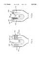
- FIGS. 1a and 1bare side perspective views of the heads of pedicle screws having threading on the outer and inner surfaces, respectively, of the upwardly extending, U-shaped channel defining, members.
- FIG. 2is a side cross-section view the rim portion which is an aspect of one embodiment of the present invention.
- FIGS. 3a and 3bare side and top views, respectively, of the post portion which is an aspect of one embodiment of the present invention.
- FIG. 4is an assembled view of the embodiment of the unitary locking cap device of the present invention which includes the rim and post portions shown in FIGS. 2, 3a, and 3b, shown mounted to the head of the pedicle screw shown in FIG. 1a.
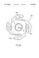
- FIGS. 5a and 5bare side cross-section and top views, respectively, of the rim portion which is an aspect of another embodiment of the present invention.
- FIG. 6is a side view of the post portion which is an aspect of another embodiment of the present invention.
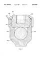
- FIG. 7is an assembled view of the embodiment of the unitary locking cap device of the present invention which includes the rim and post portions shown in FIGS. 5a, 5b, and 6, shown mounted to the head of the pedicle screw shown in FIG. 1b.
- FIGS. 1a and 1bit is instructive, for understanding the function and utility of the present invention, in its various embodiments, to describe the corresponding variance in the upper conformation of pedicle screws with which this invention may be used. More specifically, with reference to FIG. 1a, there is shown the head of a pedicle screw 100a which includes a pair of upwardly extending members 102a,104a, which define therebetween a U-shaped channel 105a. A rod of a posterior spinal implant apparatus is ideally seated in this channel 105a and is locked therein by a locking nut (not shown).
- the upwardly extending members 102a,104bare semi-circular in cross-section; mutually defining two parts of an incomplete circle (the incomplete middle portion being the channel).
- the interior surfaces 106a,108a of the upwardly extending members 102a,104aare shown as being straight and mutually parallel, however, it shall be understood that the only requirements of the interior surfaces 106a,108a is that they be smooth and sufficiently spaced apart to receive the rod.
- the exterior surfaces 110a,112a of the upwardly extending members 102a,104ahave a threading 114a thereon for receiving the locking nut for securing the rod in the channel (the locking nut preferably being the unitary locking cap of the present invention).
- a second and alternative head of a pedicle screw 100bis described.
- the head of this second pedicle screw 100bis similar to the first 100a inasmuch as it has upwardly extending members 102b,104b which define a rod receiving channel 105b therebetween.
- the outer cross-sectional conformation of these members 102b,104bdefines a partial circle as in the first pedicle screw, as well, however the outer surfaces 110b,112b of the members 102b,104b are smooth, and do not include a threading.
- the inner surfaces 106b,108b of this pedicle screw 100bare curvate and threaded, mutually defining an incomplete circle (with the channel between the two members dividing the circle).
- the threading 114b in the interior surfacesis designed to receive a threaded post, as will be set forth more fully hereinbelow with respect to the second embodiment.
- the rim portion 120 of a first embodiment of the present inventionis shown in a side cross-section view.
- This embodimentshall be understood to be used for securing rods in the receiving channels of pedicle screws of the type shown in FIG. 1a (with the threading on the outer surfaces of the upwardly extending members).
- the elementhas a generally cylindrical body 122 which has a first open end 124 and a second semi-closed end 126.
- the second end 126is defined by an inwardly directed annular flange 128 which in turn defines a concentric hole 130 through the end (hereinafter referred to as the top 126 of the rim portion).
- the inner surface wall 132 of the cylindrical body 122includes a threading 134 which is engageable with the threading 114a of a pedicle screw 100a of the type shown in FIG. 1a.
- This threading 134terminates at an axial distance which is spaced from the semi-closed end 126 of the rim portion 120.
- This unthreaded regionincludes an annular recession 136.
- the post portion 140 of this embodiment of the present inventionis shown in side and top views, respectively.
- the post portion 140includes a cylindrical shaped body having a bottom section 142 which is wider than the top section 144 thereof.
- the bottom section 142has a diameter which is substantially equal to the spacing between the upwardly extending members 102a,104a of the pedicle screw 100a with which it is utilized. (As described above, the purpose of the post portion 140 is to prevent the upwardly extending members 102a,104a from deflecting inward, thereby permitting a loosening of the threaded locking mechanism from the members.)
- the top section 144has a diameter which is slightly less than the concentric hole 130 in the top 126 of the rim portion 120. This top section 144 is provided to seat in the concentric hole 130 so as to self-center the post in the rim.
- the post portion 140further includes a plurality of deflecting arms 146 which extend radially outward from uppermost extent of the bottom section 142 (at the interface of the top and bottom sections 144,142, respectively).
- the deflecting armsextend outward to a diameter which permits them to engage the threading 134 of the rim portion 120 if deflected inwardly slightly. Therefore, during insertion, the arms 146 are deflected inward and the post 140 is threaded upwardly into the rim 120 from the bottom 124.
- the arms 146spring back into their undeflected conformation, therein seating the post within the rim securely. Inasmuch as there is no means to redeflect the arms 146 inwardly so as to reengage the threading 134, the post 140 is securely retained in the rim 120. However, becuase the diameter of the annular recess is slightly larger than the undeflected diameter of the arms 146, the post 140 is free to rotate within the rim 120, thus allowing the post to remain motionless as the combined cap assembly is threaded onto the pedicle screw 100a.
- the post portion 140is inserted into the rim portion 120 by threading the arms 146 of the post along the threading 114a of the inner surface of the rim.
- the post portionis ultimately retained within the rim by engagement of the arms 146 of the post seating in the annular recess 136 of the rim.
- This insertion processis ideally carried out at the manufacturing site such that the surgeon and operating room staff is relieved of the burden of assembling the unitary cap either pre-operatively, or during the operation.
- the unitary capis then introduced over the upwardly extending members 102a,104a of the pedicle screw head 100a.
- the inner threading 134 of the rimengages the threading 114a on the outer surfaces of the members (it being understood that the outer surface of the rim portion 120 has a conformation which permits its engagement by a wrench or other nut tightening means), and the bottom section 142 of the post 140 engages the smooth inner surfaces 106a,108a of the members 102a,104a.
- the membersare thereby locked in place such that they may not deflect inwardly and the bottom of the rim portion 120 presses against the rod 75.
- FIGS. 5a and 5bthe rim portion of a second embodiment of the present invention is shown in side and top views, respectively.
- This embodimentis illustrated in a variation which is used with pedicle screw heads 100b having a threading 114b on the interior surfaces 106b,108b of the upwardly extending members 102b,104b.
- the rim portion 220 of this embodimentit comprises a generally cylindrical body 222 having smooth interior and exterior surfaces 232,221, respectively.
- the bottom end 224is open; the top end 226 including an inward and upwardly extending flange 228 which defines a concentric hole 230 in the top 226.
- This flange 228includes radial slots 231 such that it comprises pie-shaped wedges 229.
- the cylindrical body 222is has a thinned sidewall thickness at its circumferential junction 223 with the flange 228. This thinned sidewall and the radial slots 231 in the flange permit the pie-shaped wedges 229 of the flange 228 to deflect so that the concentric hole 230 may expand or contract upon the application of a force upward or downward, respectively.
- the post portion 240 of this embodimentis shown in a side cross-section view.
- the post portion 240comprises a cylindrical body 242 having an axial bore 244 extending down from the top 248 thereof which is designed to receive a screwdriving tool for selectively rotating the post.
- the external conformation of the post 240includes a threading 246 extending from the bottom 245 thereof to a point axially spaced from the top 248 of the post.
- the post 240further includes an annular recess 250.
- the exterior diameter of the postis larger than the undeflected diameter of the concentric hole 230 formed by the pie-shaped wedges of the flange 228 of the rim.
- the diameter of the annualr recess 250is smaller than the undeflected diameter of the hole 230.
- the bottom 245 of the postis shown in this preferred embodiment as having a plurality of gripping ribs 252 which are provided for securely gripping the rod which it is to engage.
- the post portion 240 of this embodimentis coupled to the rim portion 220 by upwardly deflecting pie-shaped wedges 229 of the flange 228 of the rim and inserting the top 248 of the post through the hole 230. Releasing the wedges 229 such that they snap into the annular recess 250 of the post, the post 240 and the rim 220 are coupled together inasmuch as they are co-xaially mated, but each remains rotationally independent and able to spin relative to the other.
- a retaining snap-ringmay be seated in the annular recess 250 rather than the flange 228.
- the diameter of the hole 230would be larger than the diameter of the upper portion of the post such that the retaining ring would hold the post in the rim, not the engagement of the flange in the annular recess.
- FIG. 7the fully assembled unitary cap of this embodiment is shown having been mated to the top of a pedicle screw 100b of the type shown in FIG. 1b.
- the surgeonsimply places the unitary cap assembly over the upwardly extending members 102b,104b and threadably advances the post portion along the inner threading 114b of the screw head.
- the downward force applied by the postcauses the rim portion to advance downward along the smooth exterior of the upwardly extending arms 102b,104b.
- This downward forcealso causes the wedges 229 of the flange 228 to deflect downward slightly, into the annular recess 250, further securing the rim 220 and post 240 and the rod 75 between the extending arms.
Landscapes
- Health & Medical Sciences (AREA)
- Orthopedic Medicine & Surgery (AREA)
- Life Sciences & Earth Sciences (AREA)
- Neurology (AREA)
- Surgery (AREA)
- Molecular Biology (AREA)
- General Health & Medical Sciences (AREA)
- Biomedical Technology (AREA)
- Heart & Thoracic Surgery (AREA)
- Medical Informatics (AREA)
- Nuclear Medicine, Radiotherapy & Molecular Imaging (AREA)
- Animal Behavior & Ethology (AREA)
- Engineering & Computer Science (AREA)
- Public Health (AREA)
- Veterinary Medicine (AREA)
- Surgical Instruments (AREA)
- Prostheses (AREA)
- Closures For Containers (AREA)
- Materials For Medical Uses (AREA)
- Dowels (AREA)
Abstract
Description
Claims (8)
Priority Applications (12)
| Application Number | Priority Date | Filing Date | Title |
|---|---|---|---|
| US08/641,504US5667508A (en) | 1996-05-01 | 1996-05-01 | Unitary locking cap for use with a pedicle screw |
| JP53921897AJP4087450B2 (en) | 1996-05-01 | 1997-04-30 | Single lock cap used with pedicle screw |
| HK99103177.1AHK1018196B (en) | 1996-05-01 | 1997-04-30 | A unitary locking cap for use with a pedicle screw |
| AT97921473TATE283669T1 (en) | 1996-05-01 | 1997-04-30 | CAP FOR A PEDICLE SCREW |
| EP97921473AEP0904026B1 (en) | 1996-05-01 | 1997-04-30 | A unitary locking cap for use with a pedicle screw |
| AU27500/97AAU2750097A (en) | 1996-05-01 | 1997-04-30 | A unitary locking cap for use with a pedicle screw |
| KR1019980708825AKR20000065181A (en) | 1996-05-01 | 1997-04-30 | Single locking cap for use with pedicle screws |
| PCT/US1997/007328WO1997040762A1 (en) | 1996-05-01 | 1997-04-30 | A unitary locking cap for use with a pedicle screw |
| DE69731831TDE69731831T2 (en) | 1996-05-01 | 1997-04-30 | LOCK CAP FOR A PEDICLE SCREW |
| ES97921473TES2230602T3 (en) | 1996-05-01 | 1997-04-30 | DEVICE FOR UNIT FIXING CAP THAT FIXES A ROD LOCATED IN THE HEAD PART OF A SCREW OF PEDICLE. |
| JP2006016970AJP2006142047A (en) | 1996-05-01 | 2006-01-25 | Unitary locking cap for use with pedicle screw |
| JP2007156806AJP2007275615A (en) | 1996-05-01 | 2007-06-13 | Unitary locking cap for use with pedicle screw |
Applications Claiming Priority (1)
| Application Number | Priority Date | Filing Date | Title |
|---|---|---|---|
| US08/641,504US5667508A (en) | 1996-05-01 | 1996-05-01 | Unitary locking cap for use with a pedicle screw |
Publications (1)
| Publication Number | Publication Date |
|---|---|
| US5667508Atrue US5667508A (en) | 1997-09-16 |
Family
ID=24572668
Family Applications (1)
| Application Number | Title | Priority Date | Filing Date |
|---|---|---|---|
| US08/641,504Expired - LifetimeUS5667508A (en) | 1996-05-01 | 1996-05-01 | Unitary locking cap for use with a pedicle screw |
Country Status (9)
| Country | Link |
|---|---|
| US (1) | US5667508A (en) |
| EP (1) | EP0904026B1 (en) |
| JP (3) | JP4087450B2 (en) |
| KR (1) | KR20000065181A (en) |
| AT (1) | ATE283669T1 (en) |
| AU (1) | AU2750097A (en) |
| DE (1) | DE69731831T2 (en) |
| ES (1) | ES2230602T3 (en) |
| WO (1) | WO1997040762A1 (en) |
Cited By (189)
| Publication number | Priority date | Publication date | Assignee | Title |
|---|---|---|---|---|
| US5928243A (en) | 1997-07-16 | 1999-07-27 | Spinal Concepts, Inc. | Pedicle probe and depth gage |
| US5935133A (en) | 1997-08-26 | 1999-08-10 | Spinal Concepts, Inc. | Surgical cable system and method |
| US5989250A (en) | 1996-10-24 | 1999-11-23 | Spinal Concepts, Inc. | Method and apparatus for spinal fixation |
| US6030389A (en) | 1997-08-04 | 2000-02-29 | Spinal Concepts, Inc. | System and method for stabilizing the human spine with a bone plate |
| US6045579A (en)* | 1997-05-01 | 2000-04-04 | Spinal Concepts, Inc. | Adjustable height fusion device |
| US6053921A (en) | 1997-08-26 | 2000-04-25 | Spinal Concepts, Inc. | Surgical cable system and method |
| US6132430A (en) | 1996-10-24 | 2000-10-17 | Spinal Concepts, Inc. | Spinal fixation system |
| EP0956828A3 (en)* | 1998-04-07 | 2001-03-14 | Bernd Schäfer | Osteosynthesis device with correction rod |
| FR2799949A1 (en)* | 1999-10-22 | 2001-04-27 | Abder Benazza | Spinal osteosynthesis apparatus has lengthwise supports in form of single or double spiral springs to allow for movement |
| US6238396B1 (en) | 1999-10-07 | 2001-05-29 | Blackstone Medical, Inc. | Surgical cross-connecting apparatus and related methods |
| WO2001058370A1 (en)* | 2000-02-08 | 2001-08-16 | Cross Medical Products, Inc. | Self-aligning cap nut for use with a spinal rod anchor |
| US6387097B1 (en)* | 1997-05-16 | 2002-05-14 | Scient'x Societe A Responsabilite Limitee | Implant for osteosynthesis device with hook |
| US6440137B1 (en)* | 2000-04-18 | 2002-08-27 | Andres A. Horvath | Medical fastener cap system |
| US20020120272A1 (en)* | 1998-06-17 | 2002-08-29 | Hansen Yuan | Device for securing spinal rods |
| US6454769B2 (en) | 1997-08-04 | 2002-09-24 | Spinal Concepts, Inc. | System and method for stabilizing the human spine with a bone plate |
| US20020156474A1 (en)* | 2001-04-20 | 2002-10-24 | Michael Wack | Polyaxial locking plate |
| US6524310B1 (en) | 2000-08-18 | 2003-02-25 | Blackstone Medical, Inc. | Surgical cross-connecting apparatus having locking lever |
| US6540748B2 (en) | 1999-09-27 | 2003-04-01 | Blackstone Medical, Inc. | Surgical screw system and method of use |
| US6585737B1 (en)* | 1998-04-30 | 2003-07-01 | Stryker Spine | Backbone osteosynthesis system with collar and lock |
| WO2003032863A3 (en)* | 2001-10-15 | 2003-10-02 | Gary J Reed | Orthopedic stabilization device and method |
| US6641586B2 (en) | 2002-02-01 | 2003-11-04 | Depuy Acromed, Inc. | Closure system for spinal fixation instrumentation |
| US6692500B2 (en)* | 2001-10-15 | 2004-02-17 | Gary Jack Reed | Orthopedic stabilization device and method |
| US6755830B2 (en)* | 2001-07-04 | 2004-06-29 | Sofamor S.N.C. | Connector for a spinal fixation member |
| US20040162560A1 (en)* | 2003-02-19 | 2004-08-19 | Raynor Donald E. | Implant device including threaded locking mechanism |
| US20040186473A1 (en)* | 2003-03-21 | 2004-09-23 | Cournoyer John R. | Spinal fixation devices of improved strength and rigidity |
| US6800079B2 (en)* | 2002-03-15 | 2004-10-05 | Lock-N-Stitch, Inc. | Orthopedic stabilization device and method |
| US6800078B2 (en)* | 2001-11-07 | 2004-10-05 | Lock-N-Stitch, Inc. | Orthopedic stabilization device and method |
| US6802844B2 (en) | 2001-03-26 | 2004-10-12 | Nuvasive, Inc | Spinal alignment apparatus and methods |
| US20050004678A1 (en)* | 2003-07-03 | 2005-01-06 | Richards Mark Isom | Acetabular component |
| US20050008448A1 (en)* | 2003-07-09 | 2005-01-13 | Doubler Robert L. | Precise linear fastener system and method for use |
| US20050038430A1 (en)* | 2003-08-11 | 2005-02-17 | Mckinley Laurence M. | Low profile vertebral alignment and fixation assembly |
| US20050055026A1 (en)* | 2002-10-02 | 2005-03-10 | Biedermann Motech Gmbh | Bone anchoring element |
| US20050228379A1 (en)* | 2003-06-18 | 2005-10-13 | Jackson Roger P | Upload shank swivel head bone screw spinal implant |
| US6964664B2 (en) | 2000-01-06 | 2005-11-15 | Spinal Concepts Inc. | System and method for stabilizing the human spine with a bone plate |
| US20050277924A1 (en)* | 2004-06-09 | 2005-12-15 | Centerpulse Spine-Tech, Inc. | Orthopedic fixation connector |
| US20060122610A1 (en)* | 2004-12-08 | 2006-06-08 | Culbert Brad S | Method and apparatus for spinal stabilization |
| US20060122609A1 (en)* | 2004-12-08 | 2006-06-08 | Srdjan Mirkovic | Method and apparatus for spinal stabilization |
| US20060155278A1 (en)* | 2004-10-25 | 2006-07-13 | Alphaspine, Inc. | Pedicle screw systems and methods of assembling/installing the same |
| US20060173456A1 (en)* | 2005-01-31 | 2006-08-03 | Hawkes David T | Polyaxial pedicle screw assembly |
| US7141051B2 (en) | 2003-02-05 | 2006-11-28 | Pioneer Laboratories, Inc. | Low profile spinal fixation system |
| US7179261B2 (en) | 2003-12-16 | 2007-02-20 | Depuy Spine, Inc. | Percutaneous access devices and bone anchor assemblies |
| US20070043357A1 (en)* | 2005-07-29 | 2007-02-22 | X-Spine Systems, Inc. | Capless multiaxial screw and spinal fixation assembly and method |
| US20070055242A1 (en)* | 2005-07-27 | 2007-03-08 | Bailly Frank E | Device for securing spinal rods |
| US20070073291A1 (en)* | 2005-09-12 | 2007-03-29 | Seaspine, Inc. | Implant system for Osteosynthesis |
| US20070118132A1 (en)* | 2002-07-19 | 2007-05-24 | Triage Medical, Inc. | Method and apparatus for spinal fixation |
| US20070118123A1 (en)* | 2005-11-21 | 2007-05-24 | Strausbaugh William L | Polyaxial bone anchors with increased angulation |
| US20070198062A1 (en)* | 2003-09-25 | 2007-08-23 | Nuvasive, Inc. | Surgical access system and related methods |
| US20070208344A1 (en)* | 2006-03-01 | 2007-09-06 | Sdgi Holdings, Inc. | Devices for securing elongated spinal connecting elements in bone anchors |
| US20080015584A1 (en)* | 2002-04-18 | 2008-01-17 | Aesculap Implant Systems | Screw and rod fixation assembly and device |
| EP1372539A4 (en)* | 2001-03-06 | 2008-05-14 | Sung-Kon Kim | Screw for fixing spine |
| US20080119857A1 (en)* | 2006-11-16 | 2008-05-22 | Spine Wave, Inc. | Multi-Axial Spinal Fixation System |
| US7470236B1 (en) | 1999-11-24 | 2008-12-30 | Nuvasive, Inc. | Electromyography system |
| US20090088809A1 (en)* | 2007-09-28 | 2009-04-02 | Michael Alan Fisher | Anti-Microbial Implant |
| US20090105715A1 (en)* | 2007-10-23 | 2009-04-23 | Karl Pierre Belliard | Bone fixation tensioning tool and method |
| US20090138048A1 (en)* | 2005-09-21 | 2009-05-28 | Abbott Laboratories | Instrument for tensioning a flexible tie |
| EP2082697A1 (en)* | 2008-01-28 | 2009-07-29 | Spinelab AG | Pedicular screw with a locking device |
| US7582058B1 (en) | 2002-06-26 | 2009-09-01 | Nuvasive, Inc. | Surgical access system and related methods |
| US7604655B2 (en) | 2004-10-25 | 2009-10-20 | X-Spine Systems, Inc. | Bone fixation system and method for using the same |
| EP2111810A1 (en)* | 2008-04-24 | 2009-10-28 | Zimmer Spine | System for stabilizing at least a portion of the spine |
| US20090292317A1 (en)* | 2008-05-20 | 2009-11-26 | Zimmer Spine S.A.S. | System for stabilizing at least two vertebrae |
| US7637952B2 (en) | 2002-03-11 | 2009-12-29 | Zimmer Spine, Inc. | Instrumentation and procedure for implanting spinal implant devices |
| US20090326585A1 (en)* | 2005-09-20 | 2009-12-31 | Abbott Spine | Vertebral fixing system |
| US7686835B2 (en) | 2005-10-04 | 2010-03-30 | X-Spine Systems, Inc. | Pedicle screw system with provisional locking aspects |
| US7691057B2 (en) | 2003-01-16 | 2010-04-06 | Nuvasive, Inc. | Surgical access system and related methods |
| US7766947B2 (en) | 2001-10-31 | 2010-08-03 | Ortho Development Corporation | Cervical plate for stabilizing the human spine |
| US20100211102A1 (en)* | 2007-09-25 | 2010-08-19 | Karl Pierre Belliard | Device for clamping two portions of a braid and an intervertebral implant comprising a spacer, a braid, and such a clamping device |
| US20100241175A1 (en)* | 2009-03-20 | 2010-09-23 | Spinal USA LLC | Pedicle screws and methods of using the same |
| US20100249845A1 (en)* | 2007-10-23 | 2010-09-30 | Alain Meunier | Fixing devices and stabilization systems using said fixing devices |
| US7819801B2 (en) | 2003-02-27 | 2010-10-26 | Nuvasive, Inc. | Surgical access system and related methods |
| US7833251B1 (en) | 2004-01-06 | 2010-11-16 | Nuvasive, Inc. | System and method for performing spinal fixation |
| US7905840B2 (en) | 2003-10-17 | 2011-03-15 | Nuvasive, Inc. | Surgical access system and related methods |
| US7918858B2 (en) | 2006-09-26 | 2011-04-05 | Depuy Spine, Inc. | Minimally invasive bone anchor extensions |
| US7962191B2 (en) | 1998-12-23 | 2011-06-14 | Nuvasive, Inc. | Nerve surveillance cannulae systems |
| US7959654B2 (en) | 2002-07-23 | 2011-06-14 | Zimmer Spine S.A.S. | Vertebral fixing system |
| US20110184308A1 (en)* | 2001-07-11 | 2011-07-28 | Nuvasive, Inc. | System and methods for determining nerve proximity, direction, and pathology during surgery |
| US7998176B2 (en) | 2007-06-08 | 2011-08-16 | Interventional Spine, Inc. | Method and apparatus for spinal stabilization |
| US8000782B2 (en) | 2001-09-25 | 2011-08-16 | Nuvasive, Inc. | System and methods for performing surgical procedures and assessments |
| US20110218579A1 (en)* | 2003-06-18 | 2011-09-08 | Jackson Roger P | Polyaxial bone anchor with helical capture connection, insert and dual locking assembly |
| US8062340B2 (en) | 2006-08-16 | 2011-11-22 | Pioneer Surgical Technology, Inc. | Spinal rod anchor device and method |
| US8097025B2 (en) | 2005-10-25 | 2012-01-17 | X-Spine Systems, Inc. | Pedicle screw system configured to receive a straight or curved rod |
| US8137284B2 (en) | 2002-10-08 | 2012-03-20 | Nuvasive, Inc. | Surgical access system and related methods |
| US8147421B2 (en) | 2003-01-15 | 2012-04-03 | Nuvasive, Inc. | System and methods for determining nerve direction to a surgical instrument |
| US20120150239A1 (en)* | 2010-10-15 | 2012-06-14 | Laszlo Garamszegi | Fixation screw assembly |
| US8287597B1 (en) | 2009-04-16 | 2012-10-16 | Nuvasive, Inc. | Method and apparatus for performing spine surgery |
| US8313430B1 (en) | 2006-01-11 | 2012-11-20 | Nuvasive, Inc. | Surgical access system and related methods |
| US8328851B2 (en) | 2005-07-28 | 2012-12-11 | Nuvasive, Inc. | Total disc replacement system and related methods |
| FR2980098A1 (en)* | 2011-09-15 | 2013-03-22 | Hassan Razian | SYSTEM FOR OSTEOSYNTHESIS |
| US8414588B2 (en) | 2007-10-04 | 2013-04-09 | Depuy Spine, Inc. | Methods and devices for minimally invasive spinal connection element delivery |
| US8480715B2 (en) | 2007-05-22 | 2013-07-09 | Zimmer Spine, Inc. | Spinal implant system and method |
| US8715284B2 (en) | 2001-03-30 | 2014-05-06 | Interventional Spine, Inc. | Method and apparatus for bone fixation with secondary compression |
| US8721645B2 (en) | 2007-10-11 | 2014-05-13 | Zimmer Spine | Bone fixing system and method of use |
| US8790406B1 (en) | 2011-04-01 | 2014-07-29 | William D. Smith | Systems and methods for performing spine surgery |
| WO2014147104A1 (en)* | 2013-03-22 | 2014-09-25 | Aesculap Ag | Vertebral column-stabilizing system and surgical fastening element for a vertebral column-stabilizing system |
| US8852239B2 (en) | 2013-02-15 | 2014-10-07 | Roger P Jackson | Sagittal angle screw with integral shank and receiver |
| US8870928B2 (en) | 2002-09-06 | 2014-10-28 | Roger P. Jackson | Helical guide and advancement flange with radially loaded lip |
| US8911478B2 (en) | 2012-11-21 | 2014-12-16 | Roger P. Jackson | Splay control closure for open bone anchor |
| US8926672B2 (en) | 2004-11-10 | 2015-01-06 | Roger P. Jackson | Splay control closure for open bone anchor |
| US8926670B2 (en) | 2003-06-18 | 2015-01-06 | Roger P. Jackson | Polyaxial bone screw assembly |
| US8998960B2 (en) | 2004-11-10 | 2015-04-07 | Roger P. Jackson | Polyaxial bone screw with helically wound capture connection |
| US8998959B2 (en) | 2009-06-15 | 2015-04-07 | Roger P Jackson | Polyaxial bone anchors with pop-on shank, fully constrained friction fit retainer and lock and release insert |
| US9060813B1 (en) | 2008-02-29 | 2015-06-23 | Nuvasive, Inc. | Surgical fixation system and related methods |
| US9095378B2 (en) | 2012-11-13 | 2015-08-04 | K2M, Inc. | Spinal stabilization system |
| US9131947B2 (en) | 2003-05-08 | 2015-09-15 | Nuvasive, Inc. | Neurophysiological apparatus and procedures |
| US9168069B2 (en) | 2009-06-15 | 2015-10-27 | Roger P. Jackson | Polyaxial bone anchor with pop-on shank and winged insert with lower skirt for engaging a friction fit retainer |
| US9168068B2 (en) | 2012-11-13 | 2015-10-27 | K2M, Inc. | Spinal stabilization system |
| US9186182B2 (en) | 2012-11-13 | 2015-11-17 | K2M, Inc. | Spinal stabilization system |
| US9198765B1 (en) | 2011-10-31 | 2015-12-01 | Nuvasive, Inc. | Expandable spinal fusion implants and related methods |
| US9198696B1 (en) | 2010-05-27 | 2015-12-01 | Nuvasive, Inc. | Cross-connector and related methods |
| US9247964B1 (en) | 2011-03-01 | 2016-02-02 | Nuasive, Inc. | Spinal Cross-connector |
| US9271759B2 (en) | 2012-03-09 | 2016-03-01 | Institute Of Musculoskeletal Science And Education, Ltd. | Pedicle screw assembly with locking cap |
| US9295494B2 (en) | 2010-06-28 | 2016-03-29 | K2M, Inc. | Spine stabilization system |
| US9308027B2 (en) | 2005-05-27 | 2016-04-12 | Roger P Jackson | Polyaxial bone screw with shank articulation pressure insert and method |
| US9351845B1 (en) | 2009-04-16 | 2016-05-31 | Nuvasive, Inc. | Method and apparatus for performing spine surgery |
| US20160151101A1 (en)* | 2013-07-12 | 2016-06-02 | Tama Medical Co., LTD. | Medical screw, and extraction jig for medical screw |
| US9387013B1 (en) | 2011-03-01 | 2016-07-12 | Nuvasive, Inc. | Posterior cervical fixation system |
| US9393047B2 (en) | 2009-06-15 | 2016-07-19 | Roger P. Jackson | Polyaxial bone anchor with pop-on shank and friction fit retainer with low profile edge lock |
| US9439683B2 (en) | 2007-01-26 | 2016-09-13 | Roger P Jackson | Dynamic stabilization member with molded connection |
| US9451993B2 (en) | 2014-01-09 | 2016-09-27 | Roger P. Jackson | Bi-radial pop-on cervical bone anchor |
| US9504496B2 (en) | 2009-06-15 | 2016-11-29 | Roger P. Jackson | Polyaxial bone anchor with pop-on shank, friction fit retainer and winged insert |
| US9522070B2 (en) | 2013-03-07 | 2016-12-20 | Interventional Spine, Inc. | Intervertebral implant |
| US9522028B2 (en) | 2013-07-03 | 2016-12-20 | Interventional Spine, Inc. | Method and apparatus for sacroiliac joint fixation |
| US9566092B2 (en) | 2013-10-29 | 2017-02-14 | Roger P. Jackson | Cervical bone anchor with collet retainer and outer locking sleeve |
| US9597119B2 (en) | 2014-06-04 | 2017-03-21 | Roger P. Jackson | Polyaxial bone anchor with polymer sleeve |
| US9622732B2 (en) | 2004-10-08 | 2017-04-18 | Nuvasive, Inc. | Surgical access system and related methods |
| US9636146B2 (en) | 2012-01-10 | 2017-05-02 | Roger P. Jackson | Multi-start closures for open implants |
| US9662143B2 (en) | 2004-02-27 | 2017-05-30 | Roger P Jackson | Dynamic fixation assemblies with inner core and outer coil-like member |
| US9668771B2 (en) | 2009-06-15 | 2017-06-06 | Roger P Jackson | Soft stabilization assemblies with off-set connector |
| US9707100B2 (en) | 2015-06-25 | 2017-07-18 | Institute for Musculoskeletal Science and Education, Ltd. | Interbody fusion device and system for implantation |
| US9717533B2 (en) | 2013-12-12 | 2017-08-01 | Roger P. Jackson | Bone anchor closure pivot-splay control flange form guide and advancement structure |
| US9801662B2 (en) | 2012-11-13 | 2017-10-31 | K2M, Inc. | Spinal stabilization system |
| US9808292B2 (en) | 2003-06-18 | 2017-11-07 | Roger P. Jackson | Cannulated polyaxial screw |
| US9827018B2 (en) | 2012-11-13 | 2017-11-28 | K2M, Inc. | Spinal stabilization system |
| US9827109B2 (en) | 1999-03-07 | 2017-11-28 | Nuvasive, Inc. | Methods and apparatus for performing spine surgery |
| US9839530B2 (en) | 2007-06-26 | 2017-12-12 | DePuy Synthes Products, Inc. | Highly lordosed fusion cage |
| US9877747B2 (en) | 2009-09-02 | 2018-01-30 | Globus Medical, Inc. | Spine stabilization system |
| US9883951B2 (en) | 2012-08-30 | 2018-02-06 | Interventional Spine, Inc. | Artificial disc |
| US9895236B2 (en) | 2010-06-24 | 2018-02-20 | DePuy Synthes Products, Inc. | Enhanced cage insertion assembly |
| US9907574B2 (en) | 2008-08-01 | 2018-03-06 | Roger P. Jackson | Polyaxial bone anchors with pop-on shank, friction fit fully restrained retainer, insert and tool receiving features |
| US9913727B2 (en) | 2015-07-02 | 2018-03-13 | Medos International Sarl | Expandable implant |
| US9918745B2 (en) | 2009-06-15 | 2018-03-20 | Roger P. Jackson | Polyaxial bone anchor with pop-on shank and winged insert with friction fit compressive collet |
| US9931223B2 (en) | 2008-04-05 | 2018-04-03 | DePuy Synthes Products, Inc. | Expandable intervertebral implant |
| US9974571B2 (en) | 2008-09-12 | 2018-05-22 | DePuy Synthes Products, Inc. | Spinal stabilizing and guiding fixation system |
| US9993349B2 (en) | 2002-06-27 | 2018-06-12 | DePuy Synthes Products, Inc. | Intervertebral disc |
| US10058354B2 (en) | 2013-01-28 | 2018-08-28 | Roger P. Jackson | Pivotal bone anchor assembly with frictional shank head seating surfaces |
| US10058433B2 (en) | 2012-07-26 | 2018-08-28 | DePuy Synthes Products, Inc. | Expandable implant |
| US10064658B2 (en) | 2014-06-04 | 2018-09-04 | Roger P. Jackson | Polyaxial bone anchor with insert guides |
| US10105163B2 (en) | 2009-04-15 | 2018-10-23 | DePuy Synthes Products, Inc. | Revision connector for spinal constructs |
| US10111695B2 (en) | 2001-03-30 | 2018-10-30 | DePuy Synthes Products, Inc. | Distal bone anchors for bone fixation with secondary compression |
| US10136923B2 (en) | 2007-07-20 | 2018-11-27 | DePuy Synthes Products, Inc. | Polyaxial bone fixation element |
| US10154859B2 (en) | 2008-09-29 | 2018-12-18 | DePuy Synthes Products, Inc. | Polyaxial bottom-loading screw and rod assembly |
| US10349983B2 (en) | 2003-05-22 | 2019-07-16 | Alphatec Spine, Inc. | Pivotal bone anchor assembly with biased bushing for pre-lock friction fit |
| US10390963B2 (en) | 2006-12-07 | 2019-08-27 | DePuy Synthes Products, Inc. | Intervertebral implant |
| US10398563B2 (en) | 2017-05-08 | 2019-09-03 | Medos International Sarl | Expandable cage |
| US10405892B2 (en) | 2008-11-03 | 2019-09-10 | DePuy Synthes Products, Inc. | Uni-planer bone fixation assembly |
| US10433977B2 (en) | 2008-01-17 | 2019-10-08 | DePuy Synthes Products, Inc. | Expandable intervertebral implant and associated method of manufacturing the same |
| US10500062B2 (en) | 2009-12-10 | 2019-12-10 | DePuy Synthes Products, Inc. | Bellows-like expandable interbody fusion cage |
| US10537436B2 (en) | 2016-11-01 | 2020-01-21 | DePuy Synthes Products, Inc. | Curved expandable cage |
| US10548741B2 (en) | 2010-06-29 | 2020-02-04 | DePuy Synthes Products, Inc. | Distractible intervertebral implant |
| US10888433B2 (en) | 2016-12-14 | 2021-01-12 | DePuy Synthes Products, Inc. | Intervertebral implant inserter and related methods |
| US10925647B2 (en) | 2000-12-08 | 2021-02-23 | Roger P. Jackson | Threaded closure with inwardly-facing tool engaging concave radiused structures and axial through-aperture |
| US10940016B2 (en) | 2017-07-05 | 2021-03-09 | Medos International Sarl | Expandable intervertebral fusion cage |
| US10959860B2 (en) | 2008-12-26 | 2021-03-30 | Pantheon Spinal, Llc | Method of retroperitoneal lateral insertion of spinal implants |
| US11006978B2 (en) | 2009-06-17 | 2021-05-18 | DePuy Synthes Products, Inc. | Revision connector for spinal constructs |
| US20210236172A1 (en)* | 2015-10-15 | 2021-08-05 | Seth K. WILLIAMS | Spinal rod implant extension |
| US11224464B2 (en) | 2002-05-09 | 2022-01-18 | Roger P. Jackson | Threaded closure with inwardly-facing tool engaging concave radiused structures and axial through-aperture |
| US11229457B2 (en) | 2009-06-15 | 2022-01-25 | Roger P. Jackson | Pivotal bone anchor assembly with insert tool deployment |
| US11234745B2 (en) | 2005-07-14 | 2022-02-01 | Roger P. Jackson | Polyaxial bone screw assembly with partially spherical screw head and twist in place pressure insert |
| US11298170B2 (en)* | 2019-05-17 | 2022-04-12 | Warsaw Orthopedic, Inc. | Spinal implant system and methods of use |
| US11331125B1 (en) | 2021-10-07 | 2022-05-17 | Ortho Inventions, Llc | Low profile rod-to-rod coupler |
| US11344424B2 (en) | 2017-06-14 | 2022-05-31 | Medos International Sarl | Expandable intervertebral implant and related methods |
| US20220192717A1 (en)* | 2019-04-03 | 2022-06-23 | Orthopediatrics Corp. | Bone anchor head converter |
| US11419642B2 (en) | 2003-12-16 | 2022-08-23 | Medos International Sarl | Percutaneous access devices and bone anchor assemblies |
| US11426290B2 (en) | 2015-03-06 | 2022-08-30 | DePuy Synthes Products, Inc. | Expandable intervertebral implant, system, kit and method |
| US11426286B2 (en) | 2020-03-06 | 2022-08-30 | Eit Emerging Implant Technologies Gmbh | Expandable intervertebral implant |
| US11426216B2 (en) | 2003-12-16 | 2022-08-30 | DePuy Synthes Products, Inc. | Methods and devices for minimally invasive spinal fixation element placement |
| US11446156B2 (en) | 2018-10-25 | 2022-09-20 | Medos International Sarl | Expandable intervertebral implant, inserter instrument, and related methods |
| US11452607B2 (en) | 2010-10-11 | 2022-09-27 | DePuy Synthes Products, Inc. | Expandable interspinous process spacer implant |
| US11510788B2 (en) | 2016-06-28 | 2022-11-29 | Eit Emerging Implant Technologies Gmbh | Expandable, angularly adjustable intervertebral cages |
| US11596523B2 (en) | 2016-06-28 | 2023-03-07 | Eit Emerging Implant Technologies Gmbh | Expandable and angularly adjustable articulating intervertebral cages |
| US11612491B2 (en) | 2009-03-30 | 2023-03-28 | DePuy Synthes Products, Inc. | Zero profile spinal fusion cage |
| US11752009B2 (en) | 2021-04-06 | 2023-09-12 | Medos International Sarl | Expandable intervertebral fusion cage |
| US11793504B2 (en) | 2011-08-19 | 2023-10-24 | Nuvasive, Inc. | Surgical retractor system and methods of use |
| US11850160B2 (en) | 2021-03-26 | 2023-12-26 | Medos International Sarl | Expandable lordotic intervertebral fusion cage |
| US11872143B2 (en) | 2016-10-25 | 2024-01-16 | Camber Spine Technologies, LLC | Spinal fusion implant |
| US11877935B2 (en) | 2016-10-18 | 2024-01-23 | Camber Spine Technologies, LLC | Implant with deployable blades |
| US11911287B2 (en) | 2010-06-24 | 2024-02-27 | DePuy Synthes Products, Inc. | Lateral spondylolisthesis reduction cage |
| USRE49973E1 (en) | 2013-02-28 | 2024-05-21 | DePuy Synthes Products, Inc. | Expandable intervertebral implant, system, kit and method |
| US12090064B2 (en) | 2022-03-01 | 2024-09-17 | Medos International Sarl | Stabilization members for expandable intervertebral implants, and related systems and methods |
| US12440346B2 (en) | 2023-03-31 | 2025-10-14 | DePuy Synthes Products, Inc. | Expandable intervertebral implant |
Families Citing this family (2)
| Publication number | Priority date | Publication date | Assignee | Title |
|---|---|---|---|---|
| KR100509885B1 (en)* | 2002-10-28 | 2005-08-23 | 주식회사 솔고 바이오메디칼 | Fixing apparatus in a vertebra |
| EP2977017A1 (en) | 2014-07-22 | 2016-01-27 | LfC sp. z o.o. | Pedicle anchor assembly |
Citations (3)
| Publication number | Priority date | Publication date | Assignee | Title |
|---|---|---|---|---|
| US5129388A (en)* | 1989-02-09 | 1992-07-14 | Vignaud Jean Louis | Device for supporting the spinal column |
| US5217497A (en)* | 1990-07-04 | 1993-06-08 | Mehdian Seyed M H | Apparatus for use in the treatment of spinal disorders |
| US5261912A (en)* | 1990-08-21 | 1993-11-16 | Synthes (U.S.A.) | Implant for an osteosynthesis device, in particular for spinal column correction |
Family Cites Families (1)
| Publication number | Priority date | Publication date | Assignee | Title |
|---|---|---|---|---|
| DE4307576C1 (en) | 1993-03-10 | 1994-04-21 | Biedermann Motech Gmbh | Bone screw esp. for spinal column correction - has U=shaped holder section for receiving straight or bent rod |
- 1996
- 1996-05-01USUS08/641,504patent/US5667508A/ennot_activeExpired - Lifetime
- 1997
- 1997-04-30JPJP53921897Apatent/JP4087450B2/ennot_activeExpired - Fee Related
- 1997-04-30WOPCT/US1997/007328patent/WO1997040762A1/ennot_activeApplication Discontinuation
- 1997-04-30EPEP97921473Apatent/EP0904026B1/ennot_activeExpired - Lifetime
- 1997-04-30AUAU27500/97Apatent/AU2750097A/ennot_activeAbandoned
- 1997-04-30ATAT97921473Tpatent/ATE283669T1/ennot_activeIP Right Cessation
- 1997-04-30ESES97921473Tpatent/ES2230602T3/ennot_activeExpired - Lifetime
- 1997-04-30DEDE69731831Tpatent/DE69731831T2/ennot_activeExpired - Lifetime
- 1997-04-30KRKR1019980708825Apatent/KR20000065181A/ennot_activeCeased
- 2006
- 2006-01-25JPJP2006016970Apatent/JP2006142047A/ennot_activeWithdrawn
- 2007
- 2007-06-13JPJP2007156806Apatent/JP2007275615A/ennot_activeWithdrawn
Patent Citations (3)
| Publication number | Priority date | Publication date | Assignee | Title |
|---|---|---|---|---|
| US5129388A (en)* | 1989-02-09 | 1992-07-14 | Vignaud Jean Louis | Device for supporting the spinal column |
| US5217497A (en)* | 1990-07-04 | 1993-06-08 | Mehdian Seyed M H | Apparatus for use in the treatment of spinal disorders |
| US5261912A (en)* | 1990-08-21 | 1993-11-16 | Synthes (U.S.A.) | Implant for an osteosynthesis device, in particular for spinal column correction |
Cited By (511)
| Publication number | Priority date | Publication date | Assignee | Title |
|---|---|---|---|---|
| US6613050B1 (en) | 1996-10-24 | 2003-09-02 | Spinal Concepts, Inc. | Method and apparatus for spinal fixation |
| US6595992B1 (en) | 1996-10-24 | 2003-07-22 | Spinal Concepts, Inc. | Method and apparatus for spinal fixation |
| US5989250A (en) | 1996-10-24 | 1999-11-23 | Spinal Concepts, Inc. | Method and apparatus for spinal fixation |
| US6562040B1 (en) | 1996-10-24 | 2003-05-13 | Spinal Concepts, Inc. | Spinal fixation system |
| US6132430A (en) | 1996-10-24 | 2000-10-17 | Spinal Concepts, Inc. | Spinal fixation system |
| US6416515B1 (en) | 1996-10-24 | 2002-07-09 | Spinal Concepts, Inc. | Spinal fixation system |
| US6576016B1 (en) | 1997-05-01 | 2003-06-10 | Spinal Concepts, Inc. | Adjustable height fusion device |
| US6045579A (en)* | 1997-05-01 | 2000-04-04 | Spinal Concepts, Inc. | Adjustable height fusion device |
| US6080193A (en) | 1997-05-01 | 2000-06-27 | Spinal Concepts, Inc. | Adjustable height fusion device |
| US6387097B1 (en)* | 1997-05-16 | 2002-05-14 | Scient'x Societe A Responsabilite Limitee | Implant for osteosynthesis device with hook |
| US5928243A (en) | 1997-07-16 | 1999-07-27 | Spinal Concepts, Inc. | Pedicle probe and depth gage |
| US6454769B2 (en) | 1997-08-04 | 2002-09-24 | Spinal Concepts, Inc. | System and method for stabilizing the human spine with a bone plate |
| US6030389A (en) | 1997-08-04 | 2000-02-29 | Spinal Concepts, Inc. | System and method for stabilizing the human spine with a bone plate |
| US6682533B1 (en) | 1997-08-26 | 2004-01-27 | Spinal Concepts, Inc. | Surgical cable system and method |
| US6053921A (en) | 1997-08-26 | 2000-04-25 | Spinal Concepts, Inc. | Surgical cable system and method |
| US5935133A (en) | 1997-08-26 | 1999-08-10 | Spinal Concepts, Inc. | Surgical cable system and method |
| US5964769A (en) | 1997-08-26 | 1999-10-12 | Spinal Concepts, Inc. | Surgical cable system and method |
| US6391030B1 (en) | 1997-08-26 | 2002-05-21 | Spinal Concepts, Inc. | Surgical cable system and method |
| EP0956828A3 (en)* | 1998-04-07 | 2001-03-14 | Bernd Schäfer | Osteosynthesis device with correction rod |
| US6585737B1 (en)* | 1998-04-30 | 2003-07-01 | Stryker Spine | Backbone osteosynthesis system with collar and lock |
| US7909856B2 (en) | 1998-06-17 | 2011-03-22 | Howmedica Osteonics Corp. | Methods for securing spinal rods |
| US6565565B1 (en) | 1998-06-17 | 2003-05-20 | Howmedica Osteonics Corp. | Device for securing spinal rods |
| US7780703B2 (en)* | 1998-06-17 | 2010-08-24 | Howmedica Osteonics Corp. | Device for securing spinal rods |
| US7608095B2 (en) | 1998-06-17 | 2009-10-27 | Howmedica Osteonics Corp. | Device for securing spinal rods |
| US20020120272A1 (en)* | 1998-06-17 | 2002-08-29 | Hansen Yuan | Device for securing spinal rods |
| US8038702B2 (en) | 1998-06-17 | 2011-10-18 | Howmedica Osteonics Corp. | Device for securing spinal rods |
| US8313510B2 (en) | 1998-06-17 | 2012-11-20 | Howmedica Osteonics Corp. | Device for securing spinal rods |
| US20100268280A1 (en)* | 1998-06-17 | 2010-10-21 | Howmedica Osteonics Corp. | Device for securing spinal rods |
| US7819901B2 (en) | 1998-06-17 | 2010-10-26 | Howmedica Osteonics Corp. | Device for securing spinal rods |
| US8808327B2 (en) | 1998-06-17 | 2014-08-19 | Howmedica Osteonics Corp. | Device for securing spinal rods |
| US8165653B2 (en) | 1998-12-23 | 2012-04-24 | Nuvasive, Inc. | Surgical access and nerve surveillance |
| US7962191B2 (en) | 1998-12-23 | 2011-06-14 | Nuvasive, Inc. | Nerve surveillance cannulae systems |
| US9014776B2 (en) | 1998-12-23 | 2015-04-21 | Nuvasive, Inc. | Surgical access and nerve surveillance |
| US9827109B2 (en) | 1999-03-07 | 2017-11-28 | Nuvasive, Inc. | Methods and apparatus for performing spine surgery |
| US6540748B2 (en) | 1999-09-27 | 2003-04-01 | Blackstone Medical, Inc. | Surgical screw system and method of use |
| US6238396B1 (en) | 1999-10-07 | 2001-05-29 | Blackstone Medical, Inc. | Surgical cross-connecting apparatus and related methods |
| FR2799949A1 (en)* | 1999-10-22 | 2001-04-27 | Abder Benazza | Spinal osteosynthesis apparatus has lengthwise supports in form of single or double spiral springs to allow for movement |
| US9743853B2 (en) | 1999-11-24 | 2017-08-29 | Nuvasive, Inc. | Electromyography system |
| US7963927B2 (en) | 1999-11-24 | 2011-06-21 | Nuvasive, Inc. | Electromyography system |
| US7470236B1 (en) | 1999-11-24 | 2008-12-30 | Nuvasive, Inc. | Electromyography system |
| US8025677B2 (en) | 2000-01-06 | 2011-09-27 | Zimmer Spine, Inc. | System and method for stabilizing the human spine with a bone plate |
| US6964664B2 (en) | 2000-01-06 | 2005-11-15 | Spinal Concepts Inc. | System and method for stabilizing the human spine with a bone plate |
| WO2001058370A1 (en)* | 2000-02-08 | 2001-08-16 | Cross Medical Products, Inc. | Self-aligning cap nut for use with a spinal rod anchor |
| US6440137B1 (en)* | 2000-04-18 | 2002-08-27 | Andres A. Horvath | Medical fastener cap system |
| US6524310B1 (en) | 2000-08-18 | 2003-02-25 | Blackstone Medical, Inc. | Surgical cross-connecting apparatus having locking lever |
| US10925647B2 (en) | 2000-12-08 | 2021-02-23 | Roger P. Jackson | Threaded closure with inwardly-facing tool engaging concave radiused structures and axial through-aperture |
| US10993745B2 (en) | 2000-12-08 | 2021-05-04 | Roger P. Jackson | Threaded closure mechanism having a closed body with inwardly-facing concave radiused tool engaging surfaces and a downwardly extending rod-engaging structure |
| EP1372539A4 (en)* | 2001-03-06 | 2008-05-14 | Sung-Kon Kim | Screw for fixing spine |
| US6802844B2 (en) | 2001-03-26 | 2004-10-12 | Nuvasive, Inc | Spinal alignment apparatus and methods |
| US20080071275A1 (en)* | 2001-03-26 | 2008-03-20 | Nu Vasive, Inc. | Spinal alignment system and related methods |
| US20040260287A1 (en)* | 2001-03-26 | 2004-12-23 | Nuvasive, Inc. | Spinal alignment system and related methods |
| US9408648B2 (en) | 2001-03-30 | 2016-08-09 | Interventional Spine, Inc. | Method and apparatus for bone fixation with secondary compression |
| US10111695B2 (en) | 2001-03-30 | 2018-10-30 | DePuy Synthes Products, Inc. | Distal bone anchors for bone fixation with secondary compression |
| US8715284B2 (en) | 2001-03-30 | 2014-05-06 | Interventional Spine, Inc. | Method and apparatus for bone fixation with secondary compression |
| US20020156474A1 (en)* | 2001-04-20 | 2002-10-24 | Michael Wack | Polyaxial locking plate |
| US20040030339A1 (en)* | 2001-04-20 | 2004-02-12 | Wack Michael A. | Dual locking plate and associated method |
| US6755830B2 (en)* | 2001-07-04 | 2004-06-29 | Sofamor S.N.C. | Connector for a spinal fixation member |
| US8050769B2 (en) | 2001-07-11 | 2011-11-01 | Nuvasive, Inc. | System and methods for determining nerve proximity, direction, and pathology during surgery |
| US20110184308A1 (en)* | 2001-07-11 | 2011-07-28 | Nuvasive, Inc. | System and methods for determining nerve proximity, direction, and pathology during surgery |
| US9931077B2 (en) | 2001-07-11 | 2018-04-03 | Nuvasive, Inc. | System and methods for determining nerve proximity, direction and pathology during surgery |
| US9456783B2 (en) | 2001-07-11 | 2016-10-04 | Nuvasive, Inc. | System and methods for determining nerve proximity, direction and pathology during surgery |
| US8055349B2 (en) | 2001-07-11 | 2011-11-08 | Nuvasive, Inc. | System and methods for determining nerve proximity, direction, and pathology during surgery |
| US9037250B2 (en) | 2001-07-11 | 2015-05-19 | Nuvasive, Inc. | System and methods for determining nerve proximity, direction and pathology during surgery |
| US10716509B2 (en) | 2001-07-11 | 2020-07-21 | Nuvasive, Inc. | System and methods for determining nerve proximity, direction and pathology during surgery |
| US8812116B2 (en) | 2001-07-11 | 2014-08-19 | Nuvasive, Inc. | System and methods for determining nerve proximity, direction, and pathology during surgery |
| US8634904B2 (en) | 2001-07-11 | 2014-01-21 | Nuvasive, Inc. | System and methods for determining nerve proximity, direction, and pathology during surgery |
| US8244343B2 (en) | 2001-09-25 | 2012-08-14 | Nuvasive, Inc. | System and methods for performing surgical procedures and assessments |
| US8265744B2 (en) | 2001-09-25 | 2012-09-11 | Nuvasive, Inc. | Systems and methods for performing surgical procedures and assessments |
| US8027716B2 (en) | 2001-09-25 | 2011-09-27 | Nuvasive, Inc. | System and methods for performing surgical procedures and assessments |
| US8768450B2 (en) | 2001-09-25 | 2014-07-01 | Nuvasive, Inc. | System and methods for performing surgical procedures and assessments |
| US8005535B2 (en) | 2001-09-25 | 2011-08-23 | Nuvasive, Inc. | System and methods for performing surgical procedures and assessments |
| US8000782B2 (en) | 2001-09-25 | 2011-08-16 | Nuvasive, Inc. | System and methods for performing surgical procedures and assessments |
| US8977352B2 (en) | 2001-09-25 | 2015-03-10 | Nuvasive, Inc. | Systems and methods for performing surgical procedures and assessments |
| US10507120B2 (en) | 2001-09-25 | 2019-12-17 | Nuvasive, Inc. | Systems and methods for performing surgical procedures and assessments |
| US8548579B2 (en) | 2001-09-25 | 2013-10-01 | Nuvasive, Inc. | System and methods for performing surgical procedures and assessments |
| US8738123B2 (en) | 2001-09-25 | 2014-05-27 | Nuvasive, Inc. | System and methods for performing surgical procedures and assessments |
| US6692500B2 (en)* | 2001-10-15 | 2004-02-17 | Gary Jack Reed | Orthopedic stabilization device and method |
| WO2003032863A3 (en)* | 2001-10-15 | 2003-10-02 | Gary J Reed | Orthopedic stabilization device and method |
| US7766947B2 (en) | 2001-10-31 | 2010-08-03 | Ortho Development Corporation | Cervical plate for stabilizing the human spine |
| US6800078B2 (en)* | 2001-11-07 | 2004-10-05 | Lock-N-Stitch, Inc. | Orthopedic stabilization device and method |
| US6641586B2 (en) | 2002-02-01 | 2003-11-04 | Depuy Acromed, Inc. | Closure system for spinal fixation instrumentation |
| US7637952B2 (en) | 2002-03-11 | 2009-12-29 | Zimmer Spine, Inc. | Instrumentation and procedure for implanting spinal implant devices |
| US6800079B2 (en)* | 2002-03-15 | 2004-10-05 | Lock-N-Stitch, Inc. | Orthopedic stabilization device and method |
| US7955363B2 (en) | 2002-04-18 | 2011-06-07 | Aesculap Implant Systems, Llc | Screw and rod fixation assembly and device |
| US8409255B2 (en) | 2002-04-18 | 2013-04-02 | Aesculap Implant Systems, Llc | Screw and rod fixation assembly and device |
| US20080015584A1 (en)* | 2002-04-18 | 2008-01-17 | Aesculap Implant Systems | Screw and rod fixation assembly and device |
| US11224464B2 (en) | 2002-05-09 | 2022-01-18 | Roger P. Jackson | Threaded closure with inwardly-facing tool engaging concave radiused structures and axial through-aperture |
| US9833227B2 (en) | 2002-06-26 | 2017-12-05 | Nuvasive, Inc. | Surgical access system and related methods |
| US9848861B2 (en) | 2002-06-26 | 2017-12-26 | Nuvasive, Inc. | Surgical access system and related methods |
| US8192356B2 (en) | 2002-06-26 | 2012-06-05 | Nuvasive, Inc. | Surgical access system and related methods |
| US8672840B2 (en) | 2002-06-26 | 2014-03-18 | Nuvasive, Inc. | Surgical access system and related methods |
| US10251633B2 (en) | 2002-06-26 | 2019-04-09 | Nuvasive, Inc. | Surgical access system and related methods |
| US9750490B2 (en) | 2002-06-26 | 2017-09-05 | Nuvasive, Inc. | Surgical access system and related methods |
| US7582058B1 (en) | 2002-06-26 | 2009-09-01 | Nuvasive, Inc. | Surgical access system and related methods |
| US9826968B2 (en) | 2002-06-26 | 2017-11-28 | Nuvasive, Inc. | Surgical access system and related methods |
| US8182423B2 (en) | 2002-06-26 | 2012-05-22 | Nuvasive, Inc. | Surgical access system and related methods |
| US8187179B2 (en) | 2002-06-26 | 2012-05-29 | Nuvasive, Inc. | Surgical access system and related methods |
| US8708899B2 (en) | 2002-06-26 | 2014-04-29 | Nuvasive, Inc. | Surgical access system and related methods |
| US8915846B2 (en) | 2002-06-26 | 2014-12-23 | Nuvasive, Inc. | Surgical access system and related methods |
| US7935051B2 (en) | 2002-06-26 | 2011-05-03 | Nuvasive, Inc. | Surgical access system and related methods |
| US10980524B2 (en) | 2002-06-26 | 2021-04-20 | Nuvasive, Inc. | Surgical access system and related methods |
| US9993349B2 (en) | 2002-06-27 | 2018-06-12 | DePuy Synthes Products, Inc. | Intervertebral disc |
| US7824429B2 (en) | 2002-07-19 | 2010-11-02 | Interventional Spine, Inc. | Method and apparatus for spinal fixation |
| US20070118132A1 (en)* | 2002-07-19 | 2007-05-24 | Triage Medical, Inc. | Method and apparatus for spinal fixation |
| US8109977B2 (en) | 2002-07-19 | 2012-02-07 | Interventional Spine, Inc. | Method and apparatus for spinal fixation |
| US20070123868A1 (en)* | 2002-07-19 | 2007-05-31 | Culbert Brad S | Method and apparatus for spinal fixation |
| US7993377B2 (en) | 2002-07-19 | 2011-08-09 | Interventional Spine, Inc. | Method and apparatus for spinal fixation |
| US8945190B2 (en) | 2002-07-19 | 2015-02-03 | Interventional Spine, Inc. | Method and apparatus for spinal fixation |
| US9713486B2 (en) | 2002-07-19 | 2017-07-25 | DePuy Synthes Products, Inc. | Method and apparatus for spinal fixation |
| US7959654B2 (en) | 2002-07-23 | 2011-06-14 | Zimmer Spine S.A.S. | Vertebral fixing system |
| US9848921B2 (en) | 2002-07-23 | 2017-12-26 | Zimmer Spine S.A.S. | Vertebral fixing system |
| US8801759B2 (en) | 2002-07-23 | 2014-08-12 | Zimmer Spine S.A.S. | Vertebral fixing system |
| US8870928B2 (en) | 2002-09-06 | 2014-10-28 | Roger P. Jackson | Helical guide and advancement flange with radially loaded lip |
| US20050055026A1 (en)* | 2002-10-02 | 2005-03-10 | Biedermann Motech Gmbh | Bone anchoring element |
| US9848892B2 (en)* | 2002-10-02 | 2017-12-26 | Biedermann Technologies Gmbh & Co. Kg | Bone anchoring element |
| US9820729B2 (en) | 2002-10-08 | 2017-11-21 | Nuvasive, Inc. | Surgical access system and related methods |
| US8663100B2 (en) | 2002-10-08 | 2014-03-04 | Nuvasive, Inc. | Surgical access system and related methods |
| US8956283B2 (en) | 2002-10-08 | 2015-02-17 | Nuvasive, Inc. | Surgical access system and related methods |
| US8679006B2 (en) | 2002-10-08 | 2014-03-25 | Nuvasive, Inc. | Surgical access system and related methods |
| US8137284B2 (en) | 2002-10-08 | 2012-03-20 | Nuvasive, Inc. | Surgical access system and related methods |
| US9572562B2 (en) | 2002-10-08 | 2017-02-21 | Nuvasive, Inc. | Surgical access system and related methods |
| US9204871B2 (en) | 2002-10-08 | 2015-12-08 | Nuvasive, Inc. | Surgical access system and related methods |
| US8512235B2 (en) | 2002-10-08 | 2013-08-20 | Nuvasive, Inc. | Surgical access system and related methods |
| US10695044B2 (en) | 2002-10-08 | 2020-06-30 | Nuvasive, Inc. | Surgical access system and related methods |
| US8192357B2 (en) | 2002-10-08 | 2012-06-05 | Nuvasive, Inc. | Surgical access system and related methods |
| US8147421B2 (en) | 2003-01-15 | 2012-04-03 | Nuvasive, Inc. | System and methods for determining nerve direction to a surgical instrument |
| US10993650B2 (en) | 2003-01-15 | 2021-05-04 | Nuvasive, Inc. | System for determining nerve direction to a surgical instrument |
| US8133173B2 (en) | 2003-01-16 | 2012-03-13 | Nuvasive, Inc. | Surgical access system and related methods |
| US8562521B2 (en) | 2003-01-16 | 2013-10-22 | Nuvasive, Inc. | Surgical access system and related methods |
| US8753270B2 (en) | 2003-01-16 | 2014-06-17 | Nuvasive, Inc. | Surgical access system and related methods |
| US7691057B2 (en) | 2003-01-16 | 2010-04-06 | Nuvasive, Inc. | Surgical access system and related methods |
| US8343046B2 (en) | 2003-01-16 | 2013-01-01 | Nuvasive, Inc. | Surgical access system and related methods |
| US9795371B2 (en) | 2003-01-16 | 2017-10-24 | Nuvasive, Inc. | Surgical access system and related methods |
| US8403841B2 (en) | 2003-01-16 | 2013-03-26 | Nuvasive, Inc. | Surgical access system and related methods |
| US8114019B2 (en) | 2003-01-16 | 2012-02-14 | Nuvasive, Inc. | Surgical access system and related methods |
| US8523768B2 (en) | 2003-01-16 | 2013-09-03 | Nuvasive, Inc. | Surgical access system and related methods |
| US8602982B2 (en) | 2003-01-16 | 2013-12-10 | Nuvasive, Inc. | Surgical access system and related methods |
| US8747307B2 (en) | 2003-01-16 | 2014-06-10 | Nuvasive, Inc. | Surgical access system and related methods |
| US11219440B2 (en) | 2003-01-16 | 2022-01-11 | Nuvasive, Inc. | Surgical access system and related methods |
| US9301743B2 (en) | 2003-01-16 | 2016-04-05 | Nuvasive, Inc. | Surgical access system and related methods |
| US8439832B2 (en) | 2003-01-16 | 2013-05-14 | Nuvasive, Inc. | Surgical access system and related methods |
| US10357238B2 (en) | 2003-01-16 | 2019-07-23 | Nuvasive, Inc. | Surgical access system and related methods |
| US8172750B2 (en) | 2003-01-16 | 2012-05-08 | Nuvasive, Inc. | Surgical access system and related methods |
| US8075590B2 (en) | 2003-02-05 | 2011-12-13 | Pioneer Surgical Technology, Inc. | Low profile spinal fixation system |
| US7141051B2 (en) | 2003-02-05 | 2006-11-28 | Pioneer Laboratories, Inc. | Low profile spinal fixation system |
| US20070055235A1 (en)* | 2003-02-05 | 2007-03-08 | Pioneer Laboratories, Inc. | Low profile spinal fixation system |
| US20070179502A1 (en)* | 2003-02-19 | 2007-08-02 | Aesculap, Inc. | Implant device including threaded locking mechanism |
| US20040162560A1 (en)* | 2003-02-19 | 2004-08-19 | Raynor Donald E. | Implant device including threaded locking mechanism |
| US8550994B2 (en) | 2003-02-27 | 2013-10-08 | Nuvasive, Inc. | Surgical access system and related methods |
| US8303498B2 (en) | 2003-02-27 | 2012-11-06 | Nuvasive, Inc. | Surgical access system and related methods |
| US7819801B2 (en) | 2003-02-27 | 2010-10-26 | Nuvasive, Inc. | Surgical access system and related methods |
| US9468405B2 (en) | 2003-02-27 | 2016-10-18 | Nuvasive, Inc. | Surgical access system and related methods |
| US7892173B2 (en) | 2003-02-27 | 2011-02-22 | Nuvasive, Inc. | Surgical access system and related methods |
| US8696559B2 (en) | 2003-02-27 | 2014-04-15 | Nuvasive, Inc. | Surgical access system and related methods |
| US20040186473A1 (en)* | 2003-03-21 | 2004-09-23 | Cournoyer John R. | Spinal fixation devices of improved strength and rigidity |
| US10695108B1 (en) | 2003-05-08 | 2020-06-30 | Nuvasive, Inc. | Neurophysiological apparatus and procedures |
| US9131947B2 (en) | 2003-05-08 | 2015-09-15 | Nuvasive, Inc. | Neurophysiological apparatus and procedures |
| US10349983B2 (en) | 2003-05-22 | 2019-07-16 | Alphatec Spine, Inc. | Pivotal bone anchor assembly with biased bushing for pre-lock friction fit |
| US8936623B2 (en) | 2003-06-18 | 2015-01-20 | Roger P. Jackson | Polyaxial bone screw assembly |
| US8926670B2 (en) | 2003-06-18 | 2015-01-06 | Roger P. Jackson | Polyaxial bone screw assembly |
| US9808292B2 (en) | 2003-06-18 | 2017-11-07 | Roger P. Jackson | Cannulated polyaxial screw |
| US9144444B2 (en) | 2003-06-18 | 2015-09-29 | Roger P Jackson | Polyaxial bone anchor with helical capture connection, insert and dual locking assembly |
| USRE46431E1 (en) | 2003-06-18 | 2017-06-13 | Roger P Jackson | Polyaxial bone anchor with helical capture connection, insert and dual locking assembly |
| US20110218579A1 (en)* | 2003-06-18 | 2011-09-08 | Jackson Roger P | Polyaxial bone anchor with helical capture connection, insert and dual locking assembly |
| US11000314B2 (en) | 2003-06-18 | 2021-05-11 | Roger P. Jackson | Cannulated polyaxial screw |
| US11426207B2 (en) | 2003-06-18 | 2022-08-30 | Roger P. Jackson | Pivotal bone anchor assembly with centrally open screw shank |
| US20050228379A1 (en)* | 2003-06-18 | 2005-10-13 | Jackson Roger P | Upload shank swivel head bone screw spinal implant |
| US8052724B2 (en)* | 2003-06-18 | 2011-11-08 | Jackson Roger P | Upload shank swivel head bone screw spinal implant |
| US7115145B2 (en)* | 2003-07-03 | 2006-10-03 | Zimmer, Inc. | Acetabular component |
| US20050004678A1 (en)* | 2003-07-03 | 2005-01-06 | Richards Mark Isom | Acetabular component |
| AU2004202927B2 (en)* | 2003-07-03 | 2009-04-23 | Zimmer, Inc. | Acetabular component |
| US7862281B2 (en) | 2003-07-09 | 2011-01-04 | Spinal, Llc | Precise linear fastener system and method for use |
| US20070286703A1 (en)* | 2003-07-09 | 2007-12-13 | Zimmer Spine, Inc. | Precise linear fastener system and method for use |
| US20050008448A1 (en)* | 2003-07-09 | 2005-01-13 | Doubler Robert L. | Precise linear fastener system and method for use |
| US7658582B2 (en) | 2003-07-09 | 2010-02-09 | Ortho Innovations, Llc | Precise linear fastener system and method for use |
| US6981973B2 (en)* | 2003-08-11 | 2006-01-03 | Mckinley Laurence M | Low profile vertebral alignment and fixation assembly |
| US20050038430A1 (en)* | 2003-08-11 | 2005-02-17 | Mckinley Laurence M. | Low profile vertebral alignment and fixation assembly |
| US8628469B2 (en) | 2003-09-25 | 2014-01-14 | Nuvasive, Inc. | Surgical access system and related methods |
| US11064934B2 (en) | 2003-09-25 | 2021-07-20 | Nuvasive, Inc. | Surgical access system and related methods |
| US8753271B1 (en) | 2003-09-25 | 2014-06-17 | Nuvasive, Inc. | Surgical access system and related methods |
| US8945004B2 (en) | 2003-09-25 | 2015-02-03 | Nuvasive, Inc. | Surgical access system and related methods |
| US20070198062A1 (en)* | 2003-09-25 | 2007-08-23 | Nuvasive, Inc. | Surgical access system and related methods |
| US8764649B2 (en) | 2003-09-25 | 2014-07-01 | Nuvasive, Inc. | Surgical access system and related methods |
| US8303515B2 (en) | 2003-09-25 | 2012-11-06 | Nuvasive, Inc. | Surgical access system and related methods |
| US8016767B2 (en) | 2003-09-25 | 2011-09-13 | Nuvasive, Inc. | Surgical access system and related methods |
| US8942801B2 (en) | 2003-09-25 | 2015-01-27 | Nuvasive, Inc. | Surgical access system and related methods |
| US10357233B2 (en) | 2003-09-25 | 2019-07-23 | Nuvasive, Inc. | Surgical access system and related methods |
| US9610071B2 (en) | 2003-09-25 | 2017-04-04 | Nuvasive, Inc. | Surgical access system and related methods |
| US9974531B2 (en) | 2003-09-25 | 2018-05-22 | Nuvasive, Inc. | Surgical access system and related methods |
| US8355780B2 (en) | 2003-09-25 | 2013-01-15 | Nuvasive, Inc. | Surgical access system and related methods |
| US9265493B2 (en) | 2003-09-25 | 2016-02-23 | Nuvasive, Inc. | Surgical access system and related methods |
| US8388527B2 (en) | 2003-09-25 | 2013-03-05 | Nuvasive, Inc. | Surgical access system and related method |
| US9314152B2 (en) | 2003-09-25 | 2016-04-19 | Nuvasive, Inc. | Surgical access system and related methods |
| US8591432B2 (en) | 2003-09-25 | 2013-11-26 | Nuvasive, Inc. | Surgical access system and related methods |
| US8556808B2 (en) | 2003-09-25 | 2013-10-15 | Nuvasive, Inc. | Surgical access system and related methods |
| US8821396B1 (en) | 2003-09-25 | 2014-09-02 | Nuvasive, Inc. | Surgical access system and related methods |
| US9788822B2 (en) | 2003-09-25 | 2017-10-17 | Nuvasive, Inc. | Surgical access system and related methods |
| US8500634B2 (en) | 2003-09-25 | 2013-08-06 | Nuvasive, Inc. | Surgical access system and related methods |
| US7905840B2 (en) | 2003-10-17 | 2011-03-15 | Nuvasive, Inc. | Surgical access system and related methods |
| US10653308B2 (en) | 2003-10-17 | 2020-05-19 | Nuvasive, Inc. | Surgical access system and related methods |
| US11419642B2 (en) | 2003-12-16 | 2022-08-23 | Medos International Sarl | Percutaneous access devices and bone anchor assemblies |
| US10299839B2 (en) | 2003-12-16 | 2019-05-28 | Medos International Sárl | Percutaneous access devices and bone anchor assemblies |
| EP2292169A3 (en)* | 2003-12-16 | 2012-10-17 | DePuy Spine Sàrl | Bone anchor assemblies |
| US9439699B2 (en) | 2003-12-16 | 2016-09-13 | Medos International Sarl | Percutaneous access devices and bone anchor assemblies |
| US11426216B2 (en) | 2003-12-16 | 2022-08-30 | DePuy Synthes Products, Inc. | Methods and devices for minimally invasive spinal fixation element placement |
| US8518082B2 (en) | 2003-12-16 | 2013-08-27 | Depuy Spine, Sarl | Percutaneous access devices and bone anchor assemblies |
| US7179261B2 (en) | 2003-12-16 | 2007-02-20 | Depuy Spine, Inc. | Percutaneous access devices and bone anchor assemblies |
| US8617210B2 (en) | 2003-12-16 | 2013-12-31 | Depuy Spine, Sarl | Percutaneous access devices and bone anchor assemblies |
| US7854751B2 (en) | 2003-12-16 | 2010-12-21 | Dupuy Spine, Inc. | Percutaneous access devices and bone anchor assemblies |
| US7833251B1 (en) | 2004-01-06 | 2010-11-16 | Nuvasive, Inc. | System and method for performing spinal fixation |
| US9662143B2 (en) | 2004-02-27 | 2017-05-30 | Roger P Jackson | Dynamic fixation assemblies with inner core and outer coil-like member |
| US7763049B2 (en)* | 2004-06-09 | 2010-07-27 | Zimmer Spine, Inc. | Orthopedic fixation connector |
| US20050277924A1 (en)* | 2004-06-09 | 2005-12-15 | Centerpulse Spine-Tech, Inc. | Orthopedic fixation connector |
| US11723644B2 (en) | 2004-10-08 | 2023-08-15 | Nuvasive, Inc. | Surgical access system and related methods |
| US9622732B2 (en) | 2004-10-08 | 2017-04-18 | Nuvasive, Inc. | Surgical access system and related methods |
| US8092504B2 (en) | 2004-10-25 | 2012-01-10 | X-Spine Systems, Inc. | Pedicle screw systems and methods of assembling/installing the same |
| US8012185B2 (en) | 2004-10-25 | 2011-09-06 | X-Spine Systems, Inc. | Pedicle screw systems and methods of assembling/installing the same |
| US8142481B2 (en) | 2004-10-25 | 2012-03-27 | X-Spine Systems, Inc. | Pedicle screw systems and methods of assembling/installing the same |
| US8147522B2 (en) | 2004-10-25 | 2012-04-03 | X-Spine Systems, Inc. | Bone fixation method |
| US7604655B2 (en) | 2004-10-25 | 2009-10-20 | X-Spine Systems, Inc. | Bone fixation system and method for using the same |
| US20060155278A1 (en)* | 2004-10-25 | 2006-07-13 | Alphaspine, Inc. | Pedicle screw systems and methods of assembling/installing the same |
| US7662172B2 (en) | 2004-10-25 | 2010-02-16 | X-Spine Systems, Inc. | Pedicle screw systems and methods of assembling/installing the same |
| US20100063553A1 (en)* | 2004-10-25 | 2010-03-11 | X-Spine Systems, Inc. | Bone fixation method |
| US20100179603A1 (en)* | 2004-10-25 | 2010-07-15 | X-Spine Systems, Inc. | Pedicle screw systems and methods of assembling/installing the same |
| US8998960B2 (en) | 2004-11-10 | 2015-04-07 | Roger P. Jackson | Polyaxial bone screw with helically wound capture connection |
| US9743957B2 (en) | 2004-11-10 | 2017-08-29 | Roger P. Jackson | Polyaxial bone screw with shank articulation pressure insert and method |
| US8926672B2 (en) | 2004-11-10 | 2015-01-06 | Roger P. Jackson | Splay control closure for open bone anchor |
| US11147591B2 (en) | 2004-11-10 | 2021-10-19 | Roger P Jackson | Pivotal bone anchor receiver assembly with threaded closure |
| US11564714B2 (en) | 2004-11-10 | 2023-01-31 | Roger P. Jackson | Spinal stabilization implant assemblies with interchangeable threaded closures |
| US11278327B2 (en) | 2004-11-10 | 2022-03-22 | Roger P. Jackson | Pivotal bone anchor receiver assembly with unitary and multi-part interchangeable threaded closures |
| US9522021B2 (en) | 2004-11-23 | 2016-12-20 | Roger P. Jackson | Polyaxial bone anchor with retainer with notch for mono-axial motion |
| US9226758B2 (en) | 2004-12-08 | 2016-01-05 | Decima Spine, Inc. | Method and apparatus for spinal stabilization |
| US20110152933A1 (en)* | 2004-12-08 | 2011-06-23 | Interventional Spine, Inc. | Method and apparatus for spinal stabilization |
| AU2005314079B2 (en)* | 2004-12-08 | 2012-07-12 | Interventional Spine, Inc. | Method and apparatus for spinal stabilization |
| WO2006063083A1 (en)* | 2004-12-08 | 2006-06-15 | Triage Medical, Inc. | Method and apparatus for spinal stabilization |
| US20060122609A1 (en)* | 2004-12-08 | 2006-06-08 | Srdjan Mirkovic | Method and apparatus for spinal stabilization |
| US7857832B2 (en) | 2004-12-08 | 2010-12-28 | Interventional Spine, Inc. | Method and apparatus for spinal stabilization |
| US7901438B2 (en) | 2004-12-08 | 2011-03-08 | Interventional Spine, Inc. | Method and apparatus for spinal stabilization |
| US9445826B2 (en) | 2004-12-08 | 2016-09-20 | Decima Spine, Inc. | Method and apparatus for spinal stabilization |
| US20060122610A1 (en)* | 2004-12-08 | 2006-06-08 | Culbert Brad S | Method and apparatus for spinal stabilization |
| US20100174314A1 (en)* | 2004-12-08 | 2010-07-08 | Srdjan Mirkovic | Method and apparatus for spinal stabilization |
| US9962189B2 (en) | 2004-12-08 | 2018-05-08 | Decima Spine, Inc. | Method and apparatus for spinal stabilization |
| US10639074B2 (en) | 2004-12-08 | 2020-05-05 | Decima Spine, Inc. | Method and apparatus for spinal stabilization |
| US7648523B2 (en) | 2004-12-08 | 2010-01-19 | Interventional Spine, Inc. | Method and apparatus for spinal stabilization |
| US10070893B2 (en) | 2004-12-08 | 2018-09-11 | Decima Spine, Inc. | Method and apparatus for spinal stabilization |
| US10667844B2 (en) | 2004-12-08 | 2020-06-02 | Decima Spine, Inc. | Method and apparatus for spinal stabilization |
| US20070016191A1 (en)* | 2004-12-08 | 2007-01-18 | Culbert Brad S | Method and apparatus for spinal stabilization |
| US20090018591A1 (en)* | 2005-01-31 | 2009-01-15 | Hawkes David T | Polyaxial Pedicle Screw Assembly |
| US7445627B2 (en) | 2005-01-31 | 2008-11-04 | Alpinespine, Llc | Polyaxial pedicle screw assembly |
| US20060173456A1 (en)* | 2005-01-31 | 2006-08-03 | Hawkes David T | Polyaxial pedicle screw assembly |
| US9308027B2 (en) | 2005-05-27 | 2016-04-12 | Roger P Jackson | Polyaxial bone screw with shank articulation pressure insert and method |
| US11234745B2 (en) | 2005-07-14 | 2022-02-01 | Roger P. Jackson | Polyaxial bone screw assembly with partially spherical screw head and twist in place pressure insert |
| US7766946B2 (en) | 2005-07-27 | 2010-08-03 | Frank Emile Bailly | Device for securing spinal rods |
| US20070055242A1 (en)* | 2005-07-27 | 2007-03-08 | Bailly Frank E | Device for securing spinal rods |
| US9168149B2 (en) | 2005-07-28 | 2015-10-27 | NaVasive, Inc. | Total disc replacement system and related methods |
| US8328851B2 (en) | 2005-07-28 | 2012-12-11 | Nuvasive, Inc. | Total disc replacement system and related methods |
| US8870960B2 (en) | 2005-07-28 | 2014-10-28 | Nuvasive, Inc. | Total disc replacement system and related methods |
| US9610171B2 (en) | 2005-07-28 | 2017-04-04 | Nuvasive, Inc. | Total disc replacement system and related methods |
| US8066745B2 (en) | 2005-07-29 | 2011-11-29 | X-Spine Systems, Inc. | Capless multiaxial screw and spinal fixation assembly and method |
| US20070043357A1 (en)* | 2005-07-29 | 2007-02-22 | X-Spine Systems, Inc. | Capless multiaxial screw and spinal fixation assembly and method |
| US8382806B2 (en) | 2005-07-29 | 2013-02-26 | X-Spine Systems, Inc. | Capless multiaxial screw and spinal fixation assembly and method |
| US20070123867A1 (en)* | 2005-07-29 | 2007-05-31 | X-Spine Systems, Inc. | Capless multiaxial screw and spinal fixation assembly and method |
| US7717943B2 (en) | 2005-07-29 | 2010-05-18 | X-Spine Systems, Inc. | Capless multiaxial screw and spinal fixation assembly and method |
| US20100204738A1 (en)* | 2005-07-29 | 2010-08-12 | X-Spine Systems, Inc. | Capless multiaxial screw and spinal fixation assembly and method |
| US7695497B2 (en) | 2005-09-12 | 2010-04-13 | Seaspine, Inc. | Implant system for osteosynthesis |
| US20070073291A1 (en)* | 2005-09-12 | 2007-03-29 | Seaspine, Inc. | Implant system for Osteosynthesis |
| US8870870B2 (en) | 2005-09-20 | 2014-10-28 | Zimmer Spine S.A.S. | Vertebral fixing system |
| US20090326585A1 (en)* | 2005-09-20 | 2009-12-31 | Abbott Spine | Vertebral fixing system |
| US8172843B2 (en) | 2005-09-20 | 2012-05-08 | Zimmer Spine S.A.S. | Vertebral fixing system |
| US9113966B2 (en) | 2005-09-20 | 2015-08-25 | Zimmer Spine S.A.S. | Vertebral fixing system |
| US9717536B2 (en) | 2005-09-20 | 2017-08-01 | Zimmer Spine S.A.S. | Vertebral fixing system |
| US9949778B2 (en) | 2005-09-21 | 2018-04-24 | Zimmer Spine S.A.S. | Spinal implant with flexible tie |
| US20090182379A1 (en)* | 2005-09-21 | 2009-07-16 | Abbott Spine | Flexible tie fastening system |
| US20110238118A1 (en)* | 2005-09-21 | 2011-09-29 | Zimmer Spine S.A.S. | Spinal implant with flexible tie |
| US8162946B2 (en) | 2005-09-21 | 2012-04-24 | Zimmer Spine S.A.S. | Instrument for tensioning a flexible tie |
| US8814910B2 (en) | 2005-09-21 | 2014-08-26 | Zimmer Spine S.A.S. | Method and instrument for tensioning a flexible tie |
| US10426537B2 (en) | 2005-09-21 | 2019-10-01 | Zimmer Spine, S.A.S. | Method and instrument for tensioning a flexible tie |
| US20090138048A1 (en)* | 2005-09-21 | 2009-05-28 | Abbott Laboratories | Instrument for tensioning a flexible tie |
| US8323318B2 (en) | 2005-09-21 | 2012-12-04 | Zimmer Spine S.A.S. | Flexible tie fastening system |
| US20110238125A1 (en)* | 2005-09-21 | 2011-09-29 | Zimmer Spine S.A.S. | Method and instrument for tensioning a flexible tie |
| US20100152788A1 (en)* | 2005-10-04 | 2010-06-17 | X-Spine Systems, Inc. | Pedicle screw system with provisional locking aspects |
| US7686835B2 (en) | 2005-10-04 | 2010-03-30 | X-Spine Systems, Inc. | Pedicle screw system with provisional locking aspects |
| US8016866B2 (en) | 2005-10-04 | 2011-09-13 | X-Spine Systems, Inc. | Pedicle screw system with provisional locking aspects |
| US8097025B2 (en) | 2005-10-25 | 2012-01-17 | X-Spine Systems, Inc. | Pedicle screw system configured to receive a straight or curved rod |
| US11432850B2 (en) | 2005-11-21 | 2022-09-06 | DePuy Synthes Products, Inc. | Polyaxial bone anchors with increased angulation |
| US20070118123A1 (en)* | 2005-11-21 | 2007-05-24 | Strausbaugh William L | Polyaxial bone anchors with increased angulation |
| US8679162B2 (en) | 2005-11-21 | 2014-03-25 | DePuy Synthes Products, LLC | Polyaxial bone anchors with increased angulation |
| US9848918B2 (en) | 2005-11-21 | 2017-12-26 | DePuy Synthes Products, Inc. | Polyaxial bone anchors with increased angulation |
| US8100946B2 (en) | 2005-11-21 | 2012-01-24 | Synthes Usa, Llc | Polyaxial bone anchors with increased angulation |
| US10595908B2 (en) | 2005-11-21 | 2020-03-24 | DePuy Sythes Products, Inc. | Polaxial bone anchors with increased angulation |
| US9504498B2 (en) | 2005-11-21 | 2016-11-29 | DePuy Synthes Products, Inc. | Polyaxial bone anchors with increased angulation |
| US8827900B1 (en) | 2006-01-11 | 2014-09-09 | Nuvasive, Inc. | Surgical access system and related methods |
| US8313430B1 (en) | 2006-01-11 | 2012-11-20 | Nuvasive, Inc. | Surgical access system and related methods |
| US20070208344A1 (en)* | 2006-03-01 | 2007-09-06 | Sdgi Holdings, Inc. | Devices for securing elongated spinal connecting elements in bone anchors |
| WO2007101268A1 (en)* | 2006-03-01 | 2007-09-07 | Warsaw Orthopedic, Inc. | Devices for securing elongated spinal connecting elements in bone anchors |
| US7641674B2 (en) | 2006-03-01 | 2010-01-05 | Warsaw Orthopedic, Inc. | Devices for securing elongated spinal connecting elements in bone anchors |
| US8062340B2 (en) | 2006-08-16 | 2011-11-22 | Pioneer Surgical Technology, Inc. | Spinal rod anchor device and method |
| US7918858B2 (en) | 2006-09-26 | 2011-04-05 | Depuy Spine, Inc. | Minimally invasive bone anchor extensions |
| US8828007B2 (en) | 2006-09-26 | 2014-09-09 | DePuy Synthes Products, LLC | Minimally invasive bone anchor extensions |
| US7918857B2 (en) | 2006-09-26 | 2011-04-05 | Depuy Spine, Inc. | Minimally invasive bone anchor extensions |
| US10448975B2 (en) | 2006-11-16 | 2019-10-22 | Spine Wave, Inc. | Multi-axial spinal fixation system |
| US20080119857A1 (en)* | 2006-11-16 | 2008-05-22 | Spine Wave, Inc. | Multi-Axial Spinal Fixation System |
| US9861395B2 (en) | 2006-11-16 | 2018-01-09 | Spine Wave, Inc. | Multi-axial spinal fixation system |
| US8162990B2 (en)* | 2006-11-16 | 2012-04-24 | Spine Wave, Inc. | Multi-axial spinal fixation system |
| US11432942B2 (en) | 2006-12-07 | 2022-09-06 | DePuy Synthes Products, Inc. | Intervertebral implant |
| US11273050B2 (en) | 2006-12-07 | 2022-03-15 | DePuy Synthes Products, Inc. | Intervertebral implant |
| US11712345B2 (en) | 2006-12-07 | 2023-08-01 | DePuy Synthes Products, Inc. | Intervertebral implant |
| US11660206B2 (en) | 2006-12-07 | 2023-05-30 | DePuy Synthes Products, Inc. | Intervertebral implant |
| US11497618B2 (en) | 2006-12-07 | 2022-11-15 | DePuy Synthes Products, Inc. | Intervertebral implant |
| US11642229B2 (en) | 2006-12-07 | 2023-05-09 | DePuy Synthes Products, Inc. | Intervertebral implant |
| US10583015B2 (en) | 2006-12-07 | 2020-03-10 | DePuy Synthes Products, Inc. | Intervertebral implant |
| US10390963B2 (en) | 2006-12-07 | 2019-08-27 | DePuy Synthes Products, Inc. | Intervertebral implant |
| US10398566B2 (en) | 2006-12-07 | 2019-09-03 | DePuy Synthes Products, Inc. | Intervertebral implant |
| US9439683B2 (en) | 2007-01-26 | 2016-09-13 | Roger P Jackson | Dynamic stabilization member with molded connection |
| US8480715B2 (en) | 2007-05-22 | 2013-07-09 | Zimmer Spine, Inc. | Spinal implant system and method |
| US11504164B2 (en) | 2007-05-23 | 2022-11-22 | Roger P. Jackson | Pivotal bone anchor assembly with horizontal tool engagement grooves and insert control surfaces |
| US7998176B2 (en) | 2007-06-08 | 2011-08-16 | Interventional Spine, Inc. | Method and apparatus for spinal stabilization |
| US9839530B2 (en) | 2007-06-26 | 2017-12-12 | DePuy Synthes Products, Inc. | Highly lordosed fusion cage |
| US10973652B2 (en) | 2007-06-26 | 2021-04-13 | DePuy Synthes Products, Inc. | Highly lordosed fusion cage |
| US11622868B2 (en) | 2007-06-26 | 2023-04-11 | DePuy Synthes Products, Inc. | Highly lordosed fusion cage |
| US10136923B2 (en) | 2007-07-20 | 2018-11-27 | DePuy Synthes Products, Inc. | Polyaxial bone fixation element |
| US11998246B2 (en) | 2007-07-20 | 2024-06-04 | DePuy Synthes Products, Inc. | Polyaxial bone fixation element |
| US10898234B2 (en) | 2007-07-20 | 2021-01-26 | DePuy Synthes Products, Inc. | Polyaxial bone fixation element |
| US11819247B2 (en) | 2007-07-20 | 2023-11-21 | DePuy Synthes Products, Inc. | Polyaxial bone fixation element |
| US11357550B2 (en) | 2007-07-20 | 2022-06-14 | DePuy Synthes Products, Inc. | Polyaxial bone fixation element |
| US8221464B2 (en) | 2007-09-25 | 2012-07-17 | Zimmer Spine, S.A.S. | Device for clamping two portions of a braid and an intervertebral implant comprising a spacer, a braid, and such a clamping device |
| US20100211102A1 (en)* | 2007-09-25 | 2010-08-19 | Karl Pierre Belliard | Device for clamping two portions of a braid and an intervertebral implant comprising a spacer, a braid, and such a clamping device |
| US10064655B2 (en) | 2007-09-28 | 2018-09-04 | DePuy Synthes Products, Inc. | Anti-microbial implant |
| US11389202B2 (en) | 2007-09-28 | 2022-07-19 | De Puy Synthes Products. Inc. | Anti-microbial implant |
| US9247973B2 (en)* | 2007-09-28 | 2016-02-02 | DePuy Synthes Products, Inc. | Anti-microbial implant |
| US20090088809A1 (en)* | 2007-09-28 | 2009-04-02 | Michael Alan Fisher | Anti-Microbial Implant |
| US10786282B2 (en) | 2007-09-28 | 2020-09-29 | DePuy Synthes Products, Inc. | Anti-microbial implant |
| US8414588B2 (en) | 2007-10-04 | 2013-04-09 | Depuy Spine, Inc. | Methods and devices for minimally invasive spinal connection element delivery |
| US8747405B2 (en) | 2007-10-11 | 2014-06-10 | Zimmer Spine | Bone fixing system and method of use |
| US9101406B2 (en) | 2007-10-11 | 2015-08-11 | Zimmer Spine | Bone fixing system and method of use |
| US8721645B2 (en) | 2007-10-11 | 2014-05-13 | Zimmer Spine | Bone fixing system and method of use |
| US8128635B2 (en) | 2007-10-23 | 2012-03-06 | Zimmer Spine S.A.S. | Bone fixation tensioning tool and method |
| US20100249845A1 (en)* | 2007-10-23 | 2010-09-30 | Alain Meunier | Fixing devices and stabilization systems using said fixing devices |
| US9204902B2 (en) | 2007-10-23 | 2015-12-08 | Zimmer Spine S.A.S | Bone fixation tensioning tool and method |
| US20090105715A1 (en)* | 2007-10-23 | 2009-04-23 | Karl Pierre Belliard | Bone fixation tensioning tool and method |
| US9204903B2 (en) | 2007-10-23 | 2015-12-08 | Zimmer Spine S.A.S. | Bone fixation tensioning tool and method |
| US8870869B2 (en) | 2007-10-23 | 2014-10-28 | Zimmer Spine | Fixing devices and stabilization systems using said fixing devices |
| US10278740B2 (en) | 2007-10-30 | 2019-05-07 | Roger P. Jackson | Pivotal bone anchor assembly with cannulated shank threaded capture connection and compression insert |
| US11197696B2 (en) | 2007-10-30 | 2021-12-14 | Roger P. Jackson | Pivotal bone anchor assembly with threaded spherical shank head having a planar top surface |
| US11051856B2 (en) | 2007-10-30 | 2021-07-06 | Roger P. Jackson | Pivotal bone anchor receiver with upper tool engagement grooves and inwardly protruding insert engaging structures |
| US10799272B2 (en) | 2007-10-30 | 2020-10-13 | Roger P. Jackson | Pivotal bone anchor assembly with cannulated shank threaded capture connection and compression insert |
| US10561445B2 (en) | 2007-10-30 | 2020-02-18 | Roger P. Jackson | Pivotal bone anchor assembly with cannulated shank threaded capture connection and compression insert |
| US10433977B2 (en) | 2008-01-17 | 2019-10-08 | DePuy Synthes Products, Inc. | Expandable intervertebral implant and associated method of manufacturing the same |
| US10449058B2 (en) | 2008-01-17 | 2019-10-22 | DePuy Synthes Products, Inc. | Expandable intervertebral implant and associated method of manufacturing the same |
| US11737881B2 (en) | 2008-01-17 | 2023-08-29 | DePuy Synthes Products, Inc. | Expandable intervertebral implant and associated method of manufacturing the same |
| EP2082697A1 (en)* | 2008-01-28 | 2009-07-29 | Spinelab AG | Pedicular screw with a locking device |
| US20090254128A1 (en)* | 2008-01-28 | 2009-10-08 | Thomas Zehnder | Pedicle screw with a closure device |
| US8075598B2 (en) | 2008-01-28 | 2011-12-13 | Spinelab Ag | Pedicle screw with a closure device |
| US9060813B1 (en) | 2008-02-29 | 2015-06-23 | Nuvasive, Inc. | Surgical fixation system and related methods |
| US9931223B2 (en) | 2008-04-05 | 2018-04-03 | DePuy Synthes Products, Inc. | Expandable intervertebral implant |
| US11712341B2 (en) | 2008-04-05 | 2023-08-01 | DePuy Synthes Products, Inc. | Expandable intervertebral implant |
| US11712342B2 (en) | 2008-04-05 | 2023-08-01 | DePuy Synthes Products, Inc. | Expandable intervertebral implant |
| US9993350B2 (en) | 2008-04-05 | 2018-06-12 | DePuy Synthes Products, Inc. | Expandable intervertebral implant |
| US10449056B2 (en) | 2008-04-05 | 2019-10-22 | DePuy Synthes Products, Inc. | Expandable intervertebral implant |
| US11617655B2 (en) | 2008-04-05 | 2023-04-04 | DePuy Synthes Products, Inc. | Expandable intervertebral implant |
| US12023255B2 (en) | 2008-04-05 | 2024-07-02 | DePuy Synthes Products, Inc. | Expandable inter vertebral implant |
| US11602438B2 (en) | 2008-04-05 | 2023-03-14 | DePuy Synthes Products, Inc. | Expandable intervertebral implant |
| US11701234B2 (en) | 2008-04-05 | 2023-07-18 | DePuy Synthes Products, Inc. | Expandable intervertebral implant |
| US12011361B2 (en) | 2008-04-05 | 2024-06-18 | DePuy Synthes Products, Inc. | Expandable intervertebral implant |
| US11707359B2 (en) | 2008-04-05 | 2023-07-25 | DePuy Synthes Products, Inc. | Expandable intervertebral implant |
| US20090270920A1 (en)* | 2008-04-24 | 2009-10-29 | Zimmer Spine S.A.S. | System for Stabilizing at Least a Portion of the Spine |
| US8845689B2 (en) | 2008-04-24 | 2014-09-30 | Zimmer Spine S.A.S. | System for stabilizing at least a portion of the spine |
| EP2111810A1 (en)* | 2008-04-24 | 2009-10-28 | Zimmer Spine | System for stabilizing at least a portion of the spine |
| WO2009130276A1 (en)* | 2008-04-24 | 2009-10-29 | Zimmer Spine | System for stabilizing at least a portion of the spine |
| US20090292317A1 (en)* | 2008-05-20 | 2009-11-26 | Zimmer Spine S.A.S. | System for stabilizing at least two vertebrae |
| US8663283B2 (en) | 2008-05-20 | 2014-03-04 | Zimmer Spine S.A.S. | System for stabilizing at least two vertebrae |
| US9907574B2 (en) | 2008-08-01 | 2018-03-06 | Roger P. Jackson | Polyaxial bone anchors with pop-on shank, friction fit fully restrained retainer, insert and tool receiving features |
| US9974571B2 (en) | 2008-09-12 | 2018-05-22 | DePuy Synthes Products, Inc. | Spinal stabilizing and guiding fixation system |
| US11890037B2 (en) | 2008-09-12 | 2024-02-06 | DePuy Synthes Products, Inc. | Spinal stabilizing and guiding fixation system |
| US11129648B2 (en) | 2008-09-12 | 2021-09-28 | DePuy Synthes Products, Inc. | Spinal stabilizing and guiding fixation system |
| US10154859B2 (en) | 2008-09-29 | 2018-12-18 | DePuy Synthes Products, Inc. | Polyaxial bottom-loading screw and rod assembly |
| US10709479B2 (en) | 2008-09-29 | 2020-07-14 | DePuy Synthes Products, Inc. | Polyaxial bottom-loading screw and rod assembly |
| US10405892B2 (en) | 2008-11-03 | 2019-09-10 | DePuy Synthes Products, Inc. | Uni-planer bone fixation assembly |
| US11484348B2 (en) | 2008-11-03 | 2022-11-01 | DePuy Synthes Products, Inc. | Uni-planer bone fixation assembly |
| US12383411B2 (en) | 2008-12-26 | 2025-08-12 | Pantheon Spinal, Llc | Spinal surgery methods and devices |
| US10959860B2 (en) | 2008-12-26 | 2021-03-30 | Pantheon Spinal, Llc | Method of retroperitoneal lateral insertion of spinal implants |
| US11969359B2 (en) | 2008-12-26 | 2024-04-30 | Pantheon Spinal, Llc | Method of retroperitoneal lateral insertion of spinal implants |
| US8882809B2 (en) | 2009-03-20 | 2014-11-11 | Spinal Usa, Inc. | Pedicle screws and methods of using the same |
| US8241341B2 (en) | 2009-03-20 | 2012-08-14 | Spinal Usa, Inc. | Pedicle screws and methods of using the same |
| US20100241175A1 (en)* | 2009-03-20 | 2010-09-23 | Spinal USA LLC | Pedicle screws and methods of using the same |
| US9254151B2 (en) | 2009-03-20 | 2016-02-09 | Spinal Usa, Inc. | Pedicle screws and methods of using the same |
| US12097124B2 (en) | 2009-03-30 | 2024-09-24 | DePuy Synthes Products, Inc. | Zero profile spinal fusion cage |
| US11612491B2 (en) | 2009-03-30 | 2023-03-28 | DePuy Synthes Products, Inc. | Zero profile spinal fusion cage |
| US11020152B2 (en) | 2009-04-15 | 2021-06-01 | DePuy Synthes Products, Inc. | Revision connector for spinal constructs |
| US10105163B2 (en) | 2009-04-15 | 2018-10-23 | DePuy Synthes Products, Inc. | Revision connector for spinal constructs |
| US12064145B2 (en) | 2009-04-15 | 2024-08-20 | DePuy Synthes Products, Inc. | Revision connector for spinal constructs |
| US11246713B2 (en) | 2009-04-16 | 2022-02-15 | Nuvasive, Inc. | Methods and apparatus for performing spine surgery |
| US10426627B2 (en) | 2009-04-16 | 2019-10-01 | Nuvasive, Inc. | Methods and apparatus for performing spine surgery |
| US8920500B1 (en) | 2009-04-16 | 2014-12-30 | Nuvasive, Inc. | Methods and apparatus for performing spine surgery |
| US8287597B1 (en) | 2009-04-16 | 2012-10-16 | Nuvasive, Inc. | Method and apparatus for performing spine surgery |
| US10327750B1 (en) | 2009-04-16 | 2019-06-25 | Nuvasive, Inc. | Method and apparatus for performing spine surgery |
| US11647999B1 (en) | 2009-04-16 | 2023-05-16 | Nuvasive, Inc. | Method and apparatus for performing spine surgery |
| US9351845B1 (en) | 2009-04-16 | 2016-05-31 | Nuvasive, Inc. | Method and apparatus for performing spine surgery |
| US12396863B2 (en) | 2009-04-16 | 2025-08-26 | Globus Medical Inc. | Methods and apparatus for performing spine surgery |
| US9192482B1 (en) | 2009-04-16 | 2015-11-24 | Nuvasive, Inc. | Methods and apparatus for performing spine surgery |
| US9757246B1 (en) | 2009-04-16 | 2017-09-12 | Nuvasive, Inc. | Methods and apparatus for performing spine surgery |
| US9504496B2 (en) | 2009-06-15 | 2016-11-29 | Roger P. Jackson | Polyaxial bone anchor with pop-on shank, friction fit retainer and winged insert |
| US9393047B2 (en) | 2009-06-15 | 2016-07-19 | Roger P. Jackson | Polyaxial bone anchor with pop-on shank and friction fit retainer with low profile edge lock |
| US9668771B2 (en) | 2009-06-15 | 2017-06-06 | Roger P Jackson | Soft stabilization assemblies with off-set connector |
| US9168069B2 (en) | 2009-06-15 | 2015-10-27 | Roger P. Jackson | Polyaxial bone anchor with pop-on shank and winged insert with lower skirt for engaging a friction fit retainer |
| US9918745B2 (en) | 2009-06-15 | 2018-03-20 | Roger P. Jackson | Polyaxial bone anchor with pop-on shank and winged insert with friction fit compressive collet |
| US9717534B2 (en) | 2009-06-15 | 2017-08-01 | Roger P. Jackson | Polyaxial bone anchor with pop-on shank and friction fit retainer with low profile edge lock |
| US8998959B2 (en) | 2009-06-15 | 2015-04-07 | Roger P Jackson | Polyaxial bone anchors with pop-on shank, fully constrained friction fit retainer and lock and release insert |
| US11229457B2 (en) | 2009-06-15 | 2022-01-25 | Roger P. Jackson | Pivotal bone anchor assembly with insert tool deployment |
| US11006978B2 (en) | 2009-06-17 | 2021-05-18 | DePuy Synthes Products, Inc. | Revision connector for spinal constructs |
| US12089877B2 (en) | 2009-06-17 | 2024-09-17 | DePuy Synthes Products, Inc. | Revision connector for spinal constructs |
| US9877747B2 (en) | 2009-09-02 | 2018-01-30 | Globus Medical, Inc. | Spine stabilization system |
| US10524841B2 (en) | 2009-09-02 | 2020-01-07 | Globus Medical, Inc. | Spine stabilization system |
| US10500062B2 (en) | 2009-12-10 | 2019-12-10 | DePuy Synthes Products, Inc. | Bellows-like expandable interbody fusion cage |
| US11607321B2 (en) | 2009-12-10 | 2023-03-21 | DePuy Synthes Products, Inc. | Bellows-like expandable interbody fusion cage |
| US9198696B1 (en) | 2010-05-27 | 2015-12-01 | Nuvasive, Inc. | Cross-connector and related methods |
| US10966840B2 (en) | 2010-06-24 | 2021-04-06 | DePuy Synthes Products, Inc. | Enhanced cage insertion assembly |
| US9895236B2 (en) | 2010-06-24 | 2018-02-20 | DePuy Synthes Products, Inc. | Enhanced cage insertion assembly |
| US11872139B2 (en) | 2010-06-24 | 2024-01-16 | DePuy Synthes Products, Inc. | Enhanced cage insertion assembly |
| US12318304B2 (en) | 2010-06-24 | 2025-06-03 | DePuy Synthes Products, Inc. | Lateral spondylolisthesis reduction cage |
| US11911287B2 (en) | 2010-06-24 | 2024-02-27 | DePuy Synthes Products, Inc. | Lateral spondylolisthesis reduction cage |
| US9295494B2 (en) | 2010-06-28 | 2016-03-29 | K2M, Inc. | Spine stabilization system |
| US9820779B2 (en) | 2010-06-28 | 2017-11-21 | K2M, Inc. | Spinal stabilization system |
| US11654033B2 (en) | 2010-06-29 | 2023-05-23 | DePuy Synthes Products, Inc. | Distractible intervertebral implant |
| US10548741B2 (en) | 2010-06-29 | 2020-02-04 | DePuy Synthes Products, Inc. | Distractible intervertebral implant |
| US11452607B2 (en) | 2010-10-11 | 2022-09-27 | DePuy Synthes Products, Inc. | Expandable interspinous process spacer implant |
| US20120150239A1 (en)* | 2010-10-15 | 2012-06-14 | Laszlo Garamszegi | Fixation screw assembly |
| US10433875B2 (en) | 2010-10-15 | 2019-10-08 | Phygen, Llc | Fixation screw assembly |
| US9510867B2 (en)* | 2010-10-15 | 2016-12-06 | Phygen, Llc | Fixation screw assembly |
| US10368918B2 (en) | 2011-03-01 | 2019-08-06 | Nuvasive, Inc. | Posterior cervical fixation system |
| US9247964B1 (en) | 2011-03-01 | 2016-02-02 | Nuasive, Inc. | Spinal Cross-connector |
| US10136925B2 (en) | 2011-03-01 | 2018-11-27 | Nuvasive, Inc. | Spinal cross-connector |
| US11478282B2 (en) | 2011-03-01 | 2022-10-25 | Nuvasive, Inc. | Spinal cross connector |
| US11123110B2 (en) | 2011-03-01 | 2021-09-21 | Nuvasive, Inc. | Posterior cervical fixation system |
| US9387013B1 (en) | 2011-03-01 | 2016-07-12 | Nuvasive, Inc. | Posterior cervical fixation system |
| US9770269B1 (en) | 2011-03-01 | 2017-09-26 | Nuvasive, Inc. | Spinal Cross-connector |
| US9956009B1 (en) | 2011-03-01 | 2018-05-01 | Nuvasive, Inc. | Posterior cervical fixation system |
| US10779865B2 (en) | 2011-03-01 | 2020-09-22 | Nuvasive, Inc. | Spinal cross connector |
| US9949840B1 (en) | 2011-04-01 | 2018-04-24 | William D. Smith | Systems and methods for performing spine surgery |
| US8790406B1 (en) | 2011-04-01 | 2014-07-29 | William D. Smith | Systems and methods for performing spine surgery |
| US11793504B2 (en) | 2011-08-19 | 2023-10-24 | Nuvasive, Inc. | Surgical retractor system and methods of use |
| US12256916B2 (en) | 2011-08-19 | 2025-03-25 | Nuvasive, Inc. | Surgical retractor system and methods of use |
| FR2980098A1 (en)* | 2011-09-15 | 2013-03-22 | Hassan Razian | SYSTEM FOR OSTEOSYNTHESIS |
| US9655744B1 (en) | 2011-10-31 | 2017-05-23 | Nuvasive, Inc. | Expandable spinal fusion implants and related methods |
| US9198765B1 (en) | 2011-10-31 | 2015-12-01 | Nuvasive, Inc. | Expandable spinal fusion implants and related methods |
| US10898233B2 (en) | 2012-01-10 | 2021-01-26 | Roger P. Jackson | Medical implant receivers having dual lead in closure mating thread forms and curvate extending instrument engaging grooves |
| US11399873B2 (en) | 2012-01-10 | 2022-08-02 | Roger P. Jackson | Medical implant threaded plug having a start structure |
| US9636146B2 (en) | 2012-01-10 | 2017-05-02 | Roger P. Jackson | Multi-start closures for open implants |
| US11129646B2 (en) | 2012-01-10 | 2021-09-28 | Roger P. Jackson | Medical implant threaded plug having a start structure with symmetrically shaped concave and convex leading surfaces |
| US9271759B2 (en) | 2012-03-09 | 2016-03-01 | Institute Of Musculoskeletal Science And Education, Ltd. | Pedicle screw assembly with locking cap |
| US10058433B2 (en) | 2012-07-26 | 2018-08-28 | DePuy Synthes Products, Inc. | Expandable implant |
| US9883951B2 (en) | 2012-08-30 | 2018-02-06 | Interventional Spine, Inc. | Artificial disc |
| US9186182B2 (en) | 2012-11-13 | 2015-11-17 | K2M, Inc. | Spinal stabilization system |
| US9095378B2 (en) | 2012-11-13 | 2015-08-04 | K2M, Inc. | Spinal stabilization system |
| US9801662B2 (en) | 2012-11-13 | 2017-10-31 | K2M, Inc. | Spinal stabilization system |
| US9827018B2 (en) | 2012-11-13 | 2017-11-28 | K2M, Inc. | Spinal stabilization system |
| US9168068B2 (en) | 2012-11-13 | 2015-10-27 | K2M, Inc. | Spinal stabilization system |
| US10813670B2 (en) | 2012-11-13 | 2020-10-27 | K2M, Inc. | Spinal stabilization system |
| US8911478B2 (en) | 2012-11-21 | 2014-12-16 | Roger P. Jackson | Splay control closure for open bone anchor |
| US10687855B2 (en) | 2012-11-21 | 2020-06-23 | Roger P. Jackson | Bone anchor receiver with extension portions having controlled splay allowance helically wound flange forms |
| US9770265B2 (en) | 2012-11-21 | 2017-09-26 | Roger P. Jackson | Splay control closure for open bone anchor |
| US10058354B2 (en) | 2013-01-28 | 2018-08-28 | Roger P. Jackson | Pivotal bone anchor assembly with frictional shank head seating surfaces |
| US8852239B2 (en) | 2013-02-15 | 2014-10-07 | Roger P Jackson | Sagittal angle screw with integral shank and receiver |
| USRE49973E1 (en) | 2013-02-28 | 2024-05-21 | DePuy Synthes Products, Inc. | Expandable intervertebral implant, system, kit and method |
| US11497619B2 (en) | 2013-03-07 | 2022-11-15 | DePuy Synthes Products, Inc. | Intervertebral implant |
| US10413422B2 (en) | 2013-03-07 | 2019-09-17 | DePuy Synthes Products, Inc. | Intervertebral implant |
| US11850164B2 (en) | 2013-03-07 | 2023-12-26 | DePuy Synthes Products, Inc. | Intervertebral implant |
| US9522070B2 (en) | 2013-03-07 | 2016-12-20 | Interventional Spine, Inc. | Intervertebral implant |
| WO2014147104A1 (en)* | 2013-03-22 | 2014-09-25 | Aesculap Ag | Vertebral column-stabilizing system and surgical fastening element for a vertebral column-stabilizing system |
| US9655653B2 (en) | 2013-03-22 | 2017-05-23 | Aesculap Ag | Vertebral column-stabilizing system and surgical fastening element for a vertebral column-stabilizing system |
| US10166056B2 (en) | 2013-07-03 | 2019-01-01 | DePuy Synthes Products, Inc. | Method and apparatus for sacroiliac joint fixation |
| US11006991B2 (en) | 2013-07-03 | 2021-05-18 | DePuy Synthes Products, Inc. | Method and apparatus for sacroiliac joint fixation |
| US9522028B2 (en) | 2013-07-03 | 2016-12-20 | Interventional Spine, Inc. | Method and apparatus for sacroiliac joint fixation |
| US10143509B2 (en)* | 2013-07-12 | 2018-12-04 | Tama Medical Co. LTD. | Medical screw |
| US20160151101A1 (en)* | 2013-07-12 | 2016-06-02 | Tama Medical Co., LTD. | Medical screw, and extraction jig for medical screw |
| US9566092B2 (en) | 2013-10-29 | 2017-02-14 | Roger P. Jackson | Cervical bone anchor with collet retainer and outer locking sleeve |
| US9717533B2 (en) | 2013-12-12 | 2017-08-01 | Roger P. Jackson | Bone anchor closure pivot-splay control flange form guide and advancement structure |
| US9451993B2 (en) | 2014-01-09 | 2016-09-27 | Roger P. Jackson | Bi-radial pop-on cervical bone anchor |
| US9597119B2 (en) | 2014-06-04 | 2017-03-21 | Roger P. Jackson | Polyaxial bone anchor with polymer sleeve |
| US10064658B2 (en) | 2014-06-04 | 2018-09-04 | Roger P. Jackson | Polyaxial bone anchor with insert guides |
| US11426290B2 (en) | 2015-03-06 | 2022-08-30 | DePuy Synthes Products, Inc. | Expandable intervertebral implant, system, kit and method |
| US9707100B2 (en) | 2015-06-25 | 2017-07-18 | Institute for Musculoskeletal Science and Education, Ltd. | Interbody fusion device and system for implantation |
| US9913727B2 (en) | 2015-07-02 | 2018-03-13 | Medos International Sarl | Expandable implant |
| US12185985B2 (en)* | 2015-10-15 | 2025-01-07 | Seth K. WILLIAMS | Spinal rod implant extension |
| US20210236172A1 (en)* | 2015-10-15 | 2021-08-05 | Seth K. WILLIAMS | Spinal rod implant extension |
| US11596522B2 (en) | 2016-06-28 | 2023-03-07 | Eit Emerging Implant Technologies Gmbh | Expandable and angularly adjustable intervertebral cages with articulating joint |
| US11596523B2 (en) | 2016-06-28 | 2023-03-07 | Eit Emerging Implant Technologies Gmbh | Expandable and angularly adjustable articulating intervertebral cages |
| US11510788B2 (en) | 2016-06-28 | 2022-11-29 | Eit Emerging Implant Technologies Gmbh | Expandable, angularly adjustable intervertebral cages |
| US12390343B2 (en) | 2016-06-28 | 2025-08-19 | Eit Emerging Implant Technologies Gmbh | Expandable, angularly adjustable intervertebral cages |
| US12433757B2 (en) | 2016-06-28 | 2025-10-07 | Eit Emerging Implant Technologies Gmbh | Expandable, angularly adjustable and articulating intervertebral cages |
| US12329656B2 (en) | 2016-10-18 | 2025-06-17 | Camber Spine Technologies, LLC | Implant with deployable blades |
| US11877935B2 (en) | 2016-10-18 | 2024-01-23 | Camber Spine Technologies, LLC | Implant with deployable blades |
| US11872143B2 (en) | 2016-10-25 | 2024-01-16 | Camber Spine Technologies, LLC | Spinal fusion implant |
| US10537436B2 (en) | 2016-11-01 | 2020-01-21 | DePuy Synthes Products, Inc. | Curved expandable cage |
| US10888433B2 (en) | 2016-12-14 | 2021-01-12 | DePuy Synthes Products, Inc. | Intervertebral implant inserter and related methods |
| US11446155B2 (en) | 2017-05-08 | 2022-09-20 | Medos International Sarl | Expandable cage |
| US10398563B2 (en) | 2017-05-08 | 2019-09-03 | Medos International Sarl | Expandable cage |
| US12427031B2 (en) | 2017-05-08 | 2025-09-30 | Medos International Sarl | Expandable cage |
| US11344424B2 (en) | 2017-06-14 | 2022-05-31 | Medos International Sarl | Expandable intervertebral implant and related methods |
| US10940016B2 (en) | 2017-07-05 | 2021-03-09 | Medos International Sarl | Expandable intervertebral fusion cage |
| US11446156B2 (en) | 2018-10-25 | 2022-09-20 | Medos International Sarl | Expandable intervertebral implant, inserter instrument, and related methods |
| US20220192717A1 (en)* | 2019-04-03 | 2022-06-23 | Orthopediatrics Corp. | Bone anchor head converter |
| US11298170B2 (en)* | 2019-05-17 | 2022-04-12 | Warsaw Orthopedic, Inc. | Spinal implant system and methods of use |
| US11806245B2 (en) | 2020-03-06 | 2023-11-07 | Eit Emerging Implant Technologies Gmbh | Expandable intervertebral implant |
| US11426286B2 (en) | 2020-03-06 | 2022-08-30 | Eit Emerging Implant Technologies Gmbh | Expandable intervertebral implant |
| US11850160B2 (en) | 2021-03-26 | 2023-12-26 | Medos International Sarl | Expandable lordotic intervertebral fusion cage |
| US12023258B2 (en) | 2021-04-06 | 2024-07-02 | Medos International Sarl | Expandable intervertebral fusion cage |
| US11752009B2 (en) | 2021-04-06 | 2023-09-12 | Medos International Sarl | Expandable intervertebral fusion cage |
| US11331125B1 (en) | 2021-10-07 | 2022-05-17 | Ortho Inventions, Llc | Low profile rod-to-rod coupler |
| US12090064B2 (en) | 2022-03-01 | 2024-09-17 | Medos International Sarl | Stabilization members for expandable intervertebral implants, and related systems and methods |
| US12440346B2 (en) | 2023-03-31 | 2025-10-14 | DePuy Synthes Products, Inc. | Expandable intervertebral implant |
Also Published As
| Publication number | Publication date |
|---|---|
| DE69731831D1 (en) | 2005-01-05 |
| ATE283669T1 (en) | 2004-12-15 |
| KR20000065181A (en) | 2000-11-06 |
| JP2006142047A (en) | 2006-06-08 |
| ES2230602T3 (en) | 2005-05-01 |
| JP4087450B2 (en) | 2008-05-21 |
| JP2007275615A (en) | 2007-10-25 |
| EP0904026A4 (en) | 2000-06-14 |
| EP0904026A1 (en) | 1999-03-31 |
| AU2750097A (en) | 1997-11-19 |
| DE69731831T2 (en) | 2005-12-15 |
| HK1018196A1 (en) | 1999-12-17 |
| JP2000509303A (en) | 2000-07-25 |
| EP0904026B1 (en) | 2004-12-01 |
| WO1997040762A1 (en) | 1997-11-06 |
Similar Documents
| Publication | Publication Date | Title |
|---|---|---|
| US5667508A (en) | Unitary locking cap for use with a pedicle screw | |
| US5584834A (en) | Polyaxial locking screw and coupling element assembly for use with side loading rod fixation apparatus | |
| USRE42545E1 (en) | Polyaxial pedicle screw having a threaded and tapered compression locking mechanism | |
| US5586984A (en) | Polyaxial locking screw and coupling element assembly for use with rod fixation apparatus | |
| US10463412B2 (en) | Multi-rod bone attachment member | |
| US5876402A (en) | Anterior spinal polyaxial locking screw plate assembly having recessed retaining rings | |
| US7722646B2 (en) | Polyaxial pedicle screw having a rotating locking element | |
| US5947969A (en) | Rotatable locking vertebral body screw, staple and rod assembly | |
| US5690630A (en) | Polyaxial pedicle screw | |
| US5899905A (en) | Expansion locking vertebral body screw, staple, and rod assembly | |
| US5961518A (en) | Polyaxial pedicle screw having a through bar clamp locking mechanism | |
| EP0949887B1 (en) | A modular polyaxial locking pedicle screw | |
| US5549608A (en) | Advanced polyaxial locking screw and coupling element device for use with rod fixation apparatus | |
| US5810818A (en) | Spinal hook implant having a low blade and S swivel hook | |
| US5733285A (en) | Polyaxial locking mechanism | |
| US5554157A (en) | Rod securing polyaxial locking screw and coupling element assembly | |
| JP5080622B2 (en) | Fitting element for stem screw assembly | |
| US6482207B1 (en) | Efficient assembling modular locking pedicle screw | |
| US5735851A (en) | Modular polyaxial locking pedicle screw | |
| EP0837656B1 (en) | A polyaxial locking mechanism | |
| US20170224386A1 (en) | Orthopedic fixation devices and methods of installation thereof | |
| JP2019195631A (en) | Orthopedic fixation devices and methods of installation thereof | |
| HK1018196B (en) | A unitary locking cap for use with a pedicle screw |
Legal Events
| Date | Code | Title | Description |
|---|---|---|---|
| AS | Assignment | Owner name:FASTENETIX, L.L.C., NEW JERSEY Free format text:ASSIGNMENT OF ASSIGNORS INTEREST;ASSIGNORS:ERRICO, THOMAS J.;RALPH, JAMES D.;TATAR, STEVEN;REEL/FRAME:008326/0186 Effective date:19960422 | |
| STCF | Information on status: patent grant | Free format text:PATENTED CASE | |
| AS | Assignment | Owner name:STRYKER TECHNOLOGIES CORPORATION, MICHIGAN Free format text:ASSIGNMENT OF ASSIGNORS INTEREST;ASSIGNOR:HOWMEDICA INC.;REEL/FRAME:009781/0191 Effective date:19981202 | |
| AS | Assignment | Owner name:BANK OF AMERICA NATIONAL TRUST AND SAVINGS ASSOCIA Free format text:SECURITY AGREEMENT;ASSIGNORS:STRYKER CORPORATION;STRYKER FAR EAST, INC.;REEL/FRAME:014137/0212 Effective date:19981204 Owner name:BANK OF AMERICA NATIONAL TRUST AND SAVINGS ASSOCIA Free format text:SECURITY INTEREST;ASSIGNORS:STRYKER CORPORATION;STRYKER FAR EAST, INC.;STRYKER INTERNATIONAL INC.;AND OTHERS;REEL/FRAME:009817/0001 Effective date:19981204 | |
| FPAY | Fee payment | Year of fee payment:4 | |
| SULP | Surcharge for late payment | ||
| AS | Assignment | Owner name:STRYKER CORPORATION, MICHIGAN Free format text:RELEASE OF SECURITY INTEREST;ASSIGNOR:BANK OF AMERICA, N.A. (F/K/A BANK OF AMERICA NATIONAL TRUST AND SAVINGS ASSOCIATION);REEL/FRAME:012539/0557 Effective date:20020124 Owner name:STRYKER FAR EAST, INC., MICHIGAN Free format text:RELEASE OF SECURITY INTEREST;ASSIGNOR:BANK OF AMERICA, N.A. (F/K/A BANK OF AMERICA NATIONAL TRUST AND SAVINGS ASSOCIATION);REEL/FRAME:012539/0557 Effective date:20020124 Owner name:STRYKER INTERNATIONAL, INC., MICHIGAN Free format text:RELEASE OF SECURITY INTEREST;ASSIGNOR:BANK OF AMERICA, N.A. (F/K/A BANK OF AMERICA NATIONAL TRUST AND SAVINGS ASSOCIATION);REEL/FRAME:012539/0557 Effective date:20020124 Owner name:HOWMEDICA OSTEONICS CORPORATION, MICHIGAN Free format text:RELEASE OF SECURITY INTEREST;ASSIGNOR:BANK OF AMERICA, N.A. (F/K/A BANK OF AMERICA NATIONAL TRUST AND SAVINGS ASSOCIATION);REEL/FRAME:012539/0557 Effective date:20020124 Owner name:PHYSIOTHERAPY ASSOCIATES, INC., MICHIGAN Free format text:RELEASE OF SECURITY INTEREST;ASSIGNOR:BANK OF AMERICA, N.A. (F/K/A BANK OF AMERICA NATIONAL TRUST AND SAVINGS ASSOCIATION);REEL/FRAME:012539/0557 Effective date:20020124 Owner name:STRYKER PUERTO RICO INC., MICHIGAN Free format text:RELEASE OF SECURITY INTEREST;ASSIGNOR:BANK OF AMERICA, N.A. (F/K/A BANK OF AMERICA NATIONAL TRUST AND SAVINGS ASSOCIATION);REEL/FRAME:012539/0557 Effective date:20020124 Owner name:STRYKER SALES CORPORATION, MICHIGAN Free format text:RELEASE OF SECURITY INTEREST;ASSIGNOR:BANK OF AMERICA, N.A. (F/K/A BANK OF AMERICA NATIONAL TRUST AND SAVINGS ASSOCIATION);REEL/FRAME:012539/0557 Effective date:20020124 Owner name:STRYKER TECHNOLOGIES CORPORATION, MICHIGAN Free format text:RELEASE OF SECURITY INTEREST;ASSIGNOR:BANK OF AMERICA, N.A. (F/K/A BANK OF AMERICA NATIONAL TRUST AND SAVINGS ASSOCIATION);REEL/FRAME:012539/0557 Effective date:20020124 Owner name:STRYKER FOREIGN HOLDCO, INC., MICHIGAN Free format text:RELEASE OF SECURITY INTEREST;ASSIGNOR:BANK OF AMERICA, N.A. (F/K/A BANK OF AMERICA NATIONAL TRUST AND SAVINGS ASSOCIATION);REEL/FRAME:012539/0557 Effective date:20020124 Owner name:SMD CORPORATION, MICHIGAN Free format text:RELEASE OF SECURITY INTEREST;ASSIGNOR:BANK OF AMERICA, N.A. (F/K/A BANK OF AMERICA NATIONAL TRUST AND SAVINGS ASSOCIATION);REEL/FRAME:012539/0557 Effective date:20020124 Owner name:HOWMEDICAL LEIBINGER, INC., MICHIGAN Free format text:RELEASE OF SECURITY INTEREST;ASSIGNOR:BANK OF AMERICA, N.A. (F/K/A BANK OF AMERICA NATIONAL TRUST AND SAVINGS ASSOCIATION);REEL/FRAME:012539/0557 Effective date:20020124 | |
| AS | Assignment | Owner name:K2 MEDICAL, LLC, VIRGINIA Free format text:ASSIGNMENT OF ASSIGNORS INTEREST;ASSIGNOR:FASTENETIX, LLC;REEL/FRAME:015603/0803 Effective date:20040709 | |
| FEPP | Fee payment procedure | Free format text:PAT HOLDER CLAIMS SMALL ENTITY STATUS, ENTITY STATUS SET TO SMALL (ORIGINAL EVENT CODE: LTOS); ENTITY STATUS OF PATENT OWNER: LARGE ENTITY | |
| REFU | Refund | Free format text:REFUND - PAYMENT OF MAINTENANCE FEE, 8TH YEAR, LARGE ENTITY (ORIGINAL EVENT CODE: R1552); ENTITY STATUS OF PATENT OWNER: LARGE ENTITY | |
| FPAY | Fee payment | Year of fee payment:8 | |
| FEPP | Fee payment procedure | Free format text:ENTITY STATUS SET TO SMALL (ORIGINAL EVENT CODE: SMAL); ENTITY STATUS OF PATENT OWNER: LARGE ENTITY | |
| AS | Assignment | Owner name:K2M, INC.,VIRGINIA Free format text:ASSIGNMENT OF ASSIGNORS INTEREST;ASSIGNOR:K2 MEDICAL, LLC;REEL/FRAME:018645/0554 Effective date:20061117 Owner name:K2M, INC., VIRGINIA Free format text:ASSIGNMENT OF ASSIGNORS INTEREST;ASSIGNOR:K2 MEDICAL, LLC;REEL/FRAME:018645/0554 Effective date:20061117 | |
| FEPP | Fee payment procedure | Free format text:PAT HOLDER NO LONGER CLAIMS SMALL ENTITY STATUS, ENTITY STATUS SET TO UNDISCOUNTED (ORIGINAL EVENT CODE: STOL); ENTITY STATUS OF PATENT OWNER: LARGE ENTITY | |
| FPAY | Fee payment | Year of fee payment:12 | |
| AS | Assignment | Owner name:SILICON VALLEY BANK, CALIFORNIA Free format text:SECURITY AGREEMENT;ASSIGNOR:K2M, INC.;REEL/FRAME:023032/0109 Effective date:20090729 Owner name:SILICON VALLEY BANK,CALIFORNIA Free format text:SECURITY AGREEMENT;ASSIGNOR:K2M, INC.;REEL/FRAME:023032/0109 Effective date:20090729 | |
| AS | Assignment | Owner name:K2M, LLC, VIRGINIA Free format text:CHANGE OF NAME;ASSIGNOR:K2 MEDICAL, LLC;REEL/FRAME:023427/0785 Effective date:20041128 | |
| AS | Assignment | Owner name:FATENETIX, LLC, NEW JERSEY Free format text:LETTER TERMINATING LICENSE AGREEMENT, HOWMEDICA LICENSE AGREEMENT, AND STATEMENT OF FACTS;ASSIGNOR:STRYKER CORPORATION;REEL/FRAME:023449/0320 Effective date:20040331 | |
| AS | Assignment | Owner name:FASTENETIX, LLC, NEW JERSEY Free format text:CORRECTIVE ASSIGNMENT TO CORRECT THE ASSIGNEE NAME IS INCORRECT AND SHOULD READ FASTENETIX, LLC PREVIOUSLY RECORDED ON REEL 023449 FRAME 0320;ASSIGNOR:STRYKER CORPORATION;REEL/FRAME:023456/0030 Effective date:20040331 | |
| SULP | Surcharge for late payment | ||
| AS | Assignment | Owner name:SILICON VALLEY BANK, MASSACHUSETTS Free format text:SECURITY INTEREST;ASSIGNORS:K2M, INC.;K2M HOLDING, INC.;K2M UK LIMITED;REEL/FRAME:029489/0327 Effective date:20121029 | |
| AS | Assignment | Owner name:K2M, INC., VIRGINIA Free format text:TERMINATION;ASSIGNOR:SILICON VALLEY BANK;REEL/FRAME:030918/0426 Effective date:20121029 | |
| AS | Assignment | Owner name:SILICON VALLEY BANK, CALIFORNIA Free format text:FIRST AMENDMENT TO PATENT SECURITY AGREEMENT;ASSIGNORS:K2M, INC.;K2M UNLIMITED;K2M HOLDINGS, INC.;REEL/FRAME:034034/0097 Effective date:20141021 | |
| AS | Assignment | Owner name:K2M UK LIMITED, UNITED KINGDOM Free format text:RELEASE BY SECURED PARTY;ASSIGNOR:SILICON VALLEY BANK;REEL/FRAME:047496/0001 Effective date:20181109 Owner name:K2M, INC., VIRGINIA Free format text:RELEASE BY SECURED PARTY;ASSIGNOR:SILICON VALLEY BANK;REEL/FRAME:047496/0001 Effective date:20181109 Owner name:K2M HOLDINGS, INC., VIRGINIA Free format text:RELEASE BY SECURED PARTY;ASSIGNOR:SILICON VALLEY BANK;REEL/FRAME:047496/0001 Effective date:20181109 |