US5667499A - Guide catheter unibody - Google Patents
Guide catheter unibodyDownload PDFInfo
- Publication number
- US5667499A US5667499AUS08/317,724US31772494AUS5667499AUS 5667499 AUS5667499 AUS 5667499AUS 31772494 AUS31772494 AUS 31772494AUS 5667499 AUS5667499 AUS 5667499A
- Authority
- US
- United States
- Prior art keywords
- strands
- catheter
- layer
- guide catheter
- cross
- Prior art date
- Legal status (The legal status is an assumption and is not a legal conclusion. Google has not performed a legal analysis and makes no representation as to the accuracy of the status listed.)
- Expired - Lifetime
Links
Images


Classifications
- A—HUMAN NECESSITIES
- A61—MEDICAL OR VETERINARY SCIENCE; HYGIENE
- A61M—DEVICES FOR INTRODUCING MEDIA INTO, OR ONTO, THE BODY; DEVICES FOR TRANSDUCING BODY MEDIA OR FOR TAKING MEDIA FROM THE BODY; DEVICES FOR PRODUCING OR ENDING SLEEP OR STUPOR
- A61M25/00—Catheters; Hollow probes
- A61M25/0009—Making of catheters or other medical or surgical tubes
- A61M25/0012—Making of catheters or other medical or surgical tubes with embedded structures, e.g. coils, braids, meshes, strands or radiopaque coils
- A—HUMAN NECESSITIES
- A61—MEDICAL OR VETERINARY SCIENCE; HYGIENE
- A61M—DEVICES FOR INTRODUCING MEDIA INTO, OR ONTO, THE BODY; DEVICES FOR TRANSDUCING BODY MEDIA OR FOR TAKING MEDIA FROM THE BODY; DEVICES FOR PRODUCING OR ENDING SLEEP OR STUPOR
- A61M25/00—Catheters; Hollow probes
- A61M25/0043—Catheters; Hollow probes characterised by structural features
- A61M25/005—Catheters; Hollow probes characterised by structural features with embedded materials for reinforcement, e.g. wires, coils, braids
Definitions
- the present inventionrelates to guide catheters and method of manufacturing guide catheters.
- the present inventionrelates to an improved guide catheter unibody which resists kinking and provides better torque control.
- Percutaneous transluminal angioplastyis widely accepted as an efficient and effective method for treating various obstructive disorders and vascular diseases.
- angioplastyis widely used for opening stenosis in coronary arteries, although it is also used for treatment of stenosis in other parts of the vascular system.
- Guide cathetersare well known for use in angioplasty procedures.
- the guide catheteris initially inserted into an artery, such as the femoral artery or axial artery. Subsequently, the catheter is advanced transluminally to a point where the distal tip of the guide catheter is positioned within a blood vessel, near the obstructive lesion or stenosis to be treated.
- the guide cathetermay be inserted preloaded, and contain a dilatation balloon and guide wire when it is initially inserted.
- a flexible guide wireis inserted through the lumen of the guide catheter with the distal end of the guide wire extending beyond the distal tip of the guide catheter.
- the guide wireis advanced, while monitored using fluoroscopy, to a point where the distal end of the guide wire is advanced past the arterial obstruction or stenosis.
- a dilatation balloon catheteris then inserted and advanced over the guide wire through the lumen of the guide catheter to a point where the balloon of the dilatation balloon catheter is positioned across the stenosis.
- the balloonis then inflated by supplying a fluid under pressure through an inflation lumen to the balloon.
- the balloonis inflated and deflated, pressing the lesion into the artery wall to reestablish acceptable blood flow through the artery.
- the deflated dilatation balloon catheter and guide wireare withdrawn from the patient's body using the guide catheter lumen.
- the guide catheter itselfis removed from the patient's body.
- the guide catheterIn angioplasty procedures, the guide catheter must be able to traverse tortuous pathways through blood vessels to the stenosis, in a manner atraumatic as possible. Therefore, to limit insertion time and discomfort to the patient, the guide catheter must be stiff enough to resist the formation of kinks, while at the same time possess flexibility to be responsive to maneuvering forces when guiding the catheter through the vascular system. It is important that the guide catheter exhibit good torque control such that manipulation of a proximal portion of the guide catheter is responsively translated to the tip or distal end of the catheter to curve and guide the guide catheter through the tortuous pathways.
- U.S. Pat. No. 4,665,604 to Dubowiksuggests a guide catheter which includes a base strand, a braided layer, and a final layer.
- the base strandis formed by extruding a material onto a wire mandril.
- stainless steel wireis braided over the base strand to form the braided layer. Sections of the braid which will form the body of the catheter are imbedded in the base strand by passing the base strand through a heated dye.
- the final coatingis extruded over the braided layer.
- U.S. Pat. No. 4,321,226 to Marklingsuggests a method of catheter body construction which includes a first plastic layer extruded on a core wire, a wire braid applied onto the first plastic layer, and finally, a second plastic layer extruded over the wire braid.
- the wire braidis formed of cross-wound individual stainless steel wires.
- U.S. Pat. No. 4,577,543 to Wilsonsuggests another similar method of catheter body construction which includes a generally cylindrical body having reinforcement material braided over the body.
- the body, with reinforcing strands,passes through a heated dye so that the braided strands adhere to the surface of the body.
- Wilsonsuggests that the strands may be of reinforcing material such as metal wire (steel wire) or synthetic fibers (fiberglass or aramid).
- the above types of catheter constructionstill tend to form kinks when traversing tortuous blood vessel pathways.
- the braided layerlacks a tight fitting braid and evenness of joinder at the points where the wires cross in the braid. This problem results in lack of good torque control necessary for manipulation of a proximal portion of the guide catheter to impart forces at the catheter's distal end needed to curve and guide the catheter through the blood vessels.
- a guide catheterhaving a three-layered tubular body which includes an inner sheath, a rigid intermediate sheath, and a flexible outer sheath.
- the rigid intermediate sheathis formed from extruding polymeric materials such as polycarbonates and polyamides over the interior sheath.
- Such catheterslack the structural integrity and torque response provided by a reinforcing braided layer for maneuvering the catheter through tortuous pathways of a patient's vascular system.
- the present inventionis a unibody guide catheter for use in percutaneous transluminal angioplasty procedures and a method of manufacturing such a catheter.
- the catheterincludes a base layer and a structural layer formed over the base layer.
- the structural layerincludes a plurality of strands which cross at a plurality of points. The strands are attached to each other at a substantial number of points where they cross. Additionally, a cover layer is formed over the structural layer.
- the present inventionincludes a torque control guide catheter having a unibody.
- the unibodyincludes a tubular base member, a reinforcement member and a flexible cover.
- the tubular base memberis formed from extruded plastic and has a lubricous inner surface.
- the reinforcement memberincludes strands which are bonded together and may be at least partially embedded in the tubular base member.
- the flexible coveris extruded over the tubular base member.
- the present inventionincludes a unibody guide catheter for use in percutaneous transluminal angioplasty procedures, having a multilayered unibody.
- the unibodyincludes a flexible tubular base member, a reinforcement layer, and a cover layer.
- the reinforcement layerincludes a plurality of strands which are braided onto the tubular base member. The strands are attached to each other at a substantial number of points where they cross. Additionally, the cover layer is formed over the structural layer.
- the strandsinclude a core wire having a coating.
- the coremay be formed of any metal wire, such as a stainless steel wire.
- the coatingis formed from a suitable polymeric material, such as a thermoplastic polymer.
- the strandsare attached to each other at a substantial number of points in the braid where they cross by passing the tubular member having a braided reinforcement layer through a heated dye which bonds the thermoplastic polymer coating of the strands together at the points where they cross.
- the braided reinforcement layermay be at least partially embedded in the tubular base member.
- the coatingis formed from Nylon, which is a trademark of DuPont.
- the coatingmay be formed of other suitable material.
- the coatingmay be formed from polyether block amide (PEBA) or a Nylon-PEBA blend.
- the strandsmay have a nonmetallic core.
- the strand coresmay be formed from a hard polyamide, such as a Kevlar, or Liquid Crystal Polymer (LCP).
- the present inventionincludes a method for preparing a guide catheter used in percutaneous transluminal angioplasty procedures, the method includes a plurality of steps.
- the first stepincludes forming a tubular base layer around a mandrel.
- a structural layeris formed over the base layer.
- the structural layerincludes a plurality of strands, wherein the strands cross at a plurality of points.
- the structural layer strandsare attached together.
- the structural layermay be at least partially embedded in the base layer.
- the mandrelis removed resulting in a tubular guide catheter.
- the structural layer strandsmay be formed over the base layer by known methods, such as braiding or helical wrapping.
- the strandsinclude a core wire, such as stainless steel, which has a cover layer.
- the cover layeris formed of a different material.
- the cover layeris a polymeric material, such as nylon.
- the structural layer strandsmay be attached together by many methods.
- the strandsare attached together by passing the guide catheter through a heated dye which bonds the thermoplastic polymer coatings of the strands together at a substantial number of points where they cross. It is recognized that many known methods of thermal heating may be used to bond the strand coatings together at the points where they cross.
- the strandsinclude a core having a thermoset polymer coating.
- the strandsare attached together by passing the guide catheter through a heated dye.
- the strandsare chemically bonded together at a substantial number of points where they cross.
- Upon reheating, the strandsremain chemically bonded together at a substantial number of points where they cross.
- an electrical currentmay be passed through the wire braid, heating the wire braid and attaching the strands together at the point where they cross.
- Other methodsmay be used, such as spot welding the strands together at a substantial number of points where they cross, or through the use of laser welding methods.
- the present inventionincludes a unibody catheter having a base layer and a structural layer formed over the base layer.
- the structural layerincludes a plurality of strands, wherein the strands cross at a plurality of points.
- the strandsare attached together at a substantial number of points where they cross by a metallurgical connection.
- the strandsare attached together by forming a metallic substrate over the strands.
- the metallic substratemay be formed of metal, such as nickel, or a metal blend.
- a mechanismis provided for varying the thickness of the metallic substrate.
- the metallic substrateis formed on the structural layer strands by an electrochemical process, such as an electrolytic bath.
- the strandsare attached together at a substantial number of points where they cross by a metallurgical connection.
- the metallic substrateprovides a more rigid connection with a higher tensile strength, resulting in a more responsive catheter.
- the braided strandsmay be at least partially embedded in the base layer for additional structural integrity.
- the braided structural layermay be first at least partially embedded in the base layer, and then the braided structural layer strands may be attached together. Finally, the cover layer is formed over the structural layer.
- Attaching the strands of the structural layer to each other at a substantial number of points where they crossimproves the structural integrity and improves angioplasty procedure performance response of the guide catheter.
- the improved guide catheteris less likely to kink when being guided through a patient's tortuous vascular system, leading to more successful angioplasty procedures.
- the physical looseness in the braids of the structural layeris reduced due to the fixed attachments of the strands at the points in the braid where they cross. This results in better catheter performance due to a better transmission of torque from manipulation forces at a proximal end of the catheter to the distal end of the catheter for guiding the catheter through tortuous blood vessels.
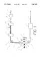
- FIG. 1is a schematic view illustrating a method of manufacturing a guide catheter according to the present invention
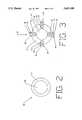
- FIG. 2is a cross-sectional view of a braid strand taken along line 2--2 of FIG. 1;
- FIG. 3is a cross-sectional view of the guide catheter taken along line 3--3 of FIG. 1;
- FIG. 4is a side view of the guide catheter taken at Area A of FIG. 1;
- FIG. 5is a cross-sectional view of the guide catheter taken along line 5--5 of FIG. 1;
- FIG. 6is a partial schematic view illustrating a method of manufacturing another embodiment of a guide catheter according to the present invention.
- FIG. 6Ais an expanded partial side view of the guide catheter of FIG. 6 showing the metallic substrate
- FIG. 7is a schematic view of the substrate process of FIG. 6;
- FIG. 8is a schematic view of an alternative embodiment of the substrate process of FIG. 6.
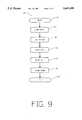
- FIG. 9is a flow diagram of the substrate process of FIG. 8.
- FIG. 1shows a schematic view of a guide catheter method of construction at 10, for manufacturing a guide catheter 12.
- Guide catheter 12is multi-layered within a single unibody, and includes a base layer 14, a structural layer 16 and a coating 18.
- base layer 14is formed by passing a mandril 20 through a first extruder 22.
- First extruder 22extrudes a suitable plastic onto mandril 20 using a commonly known conventional extrusion process.
- mandril 20is formed of silver-coated copper wire
- base layer 14is formed of a thin coat of semi-soft plastic elastomeric material having a lubricous inner surface.
- the base layer 14is formed from polytetrafluoroethylene (PTFE).
- First extruder 22extrudes a thin base layer 14 onto mandril 20.
- Mandril 20forms base layer 14 in a tubular shape, and is sized such that later removal of the mandril 20 will provide guide catheter 12 with a lumen sized to carry various intravascular catheter devices.
- FIG. 2is a sectional view of strand 28 taken along line 2--2 of FIG. 1.
- Strand 28includes a core 30 having a thermoplastic polymer coating 32.
- core 30consists of stainless steel wire, and coating 32 is a thermoplastic polymer coating, such as Nylon, approximately 0.001 inches thick.
- Braiding machine 24As catheter 12 is run through braiding machine 24, strands 28 are tightly braided onto base layer 14 to form structural layer 16.
- Braiding machine 24includes sixteen spools 26 (six shown). Braiding machine 24 tightly wraps strands 28 from spools 26 over base layer 14 in a braided pattern at, for example, a forty per inch crossings (PIC) count, to form structural layer 16.
- PICforty per inch crossings
- braiding machine 24may be a conventional wrapping device which wraps strands around a tubular body by braiding or helical wrapping.
- Heated dye 34performs two main functions. Heated dye 34 functions to embed structural layer 16 in base layer 14. Also, heated dye 34 functions to improve the structural integrity of guide catheter 12 by bonding together the braided strands of structural layer 16.
- Structural layer 16As catheter 12 passes through heated dye 34, structural layer 16 is embedded in base layer 14, as shown in FIG. 3. Structural layer 16 may be fully embedded or partially embedded in base layer 14, or alternatively, may remain flush with the base layer 14 surface. As known in the art, selected sections of structural layer 16 may be left unembedded in base layer 14 and later removed by a mechanical or electrical process to form the tip for a non-fused catheter.
- heated dye 34also performs an important function of bonding braided strands 28 together at the points where they cross.
- Bonded structural layeris indicated at 36.
- FIG. 3shows a cross section along line 3--3 of FIG. 1 of bonded structural layer 36 at a point where braided strands 28 cross. As shown in FIG. 3, strands 28 are partially embedded in base layer 14. After passing through heated dye 34, strands 28 are bonded or fused together at the locations where they cross. The bonding of braided strands 28 adds structural integrity to structural layer 16 and the finished guide catheter 12.
- braided strands 28Before braided strands 28 pass through heated dye 34, braided strands 28 overlap at the locations where they cross. The overlapping of braided strands 28 results in loose crossings in guide catheter 12 and results in a physically loose structural layer 16. It is necessary for a guide catheter to maintain a certain degree of stiffness to avoid kinking problems. Lack of structural integrity from the loose guide catheter braid leads to kinking of the guide catheter during an angioplasty procedure. When kinking occurs, the time required for successful insertion of the catheter greatly increases, thereby decreasing the patient's chance of a successful angioplasty procedure. Additionally, catheter performance is decreased from the lack of structural integrity due to torque forces being inefficiently transmitted from manipulation of a proximal end of the catheter to a distal end of the catheter for guiding the catheter through a patient's tortuous vascular system.
- FIG. 4shows a side view of catheter 12 bonded structural layer 36 at area A in FIG. 1.
- braided strands 28are coupled together at the locations where they cross.
- Heated dye 34bonds or fuses the coating 32 of strands 28 together, resulting in evenness of joinder and the braided strands 28 being fixedly secured together at their joints.
- All the strands 28may be bonded together at the point where they cross, or they may be attached to each other at a substantial number of points where they cross.
- Coupled strands 28improve the structural integrity and improve angioplasty procedure performance response of guide catheter 12.
- guide catheter 12With bonded structural layer 36, guide catheter 12 is less likely to kink when being guided through a patient's tortuous vascular system, leading to more successful angioplasty procedures. Additionally, the physical looseness in the braids is gone due to the fixed attachments of the strands at the points in the braids where they cross, resulting in better catheter performance due to a better transmission of torque from manipulation forces at a proximal end of the catheter to the distal end of the catheter for guiding the catheter through tortuous blood vessels.
- the braided strandsmay be attached together bypassing an electrical current through the braided structural layer.
- the braided strandsmay be spot welded or laser welded at the points where they cross for fusing or bonding the strands together.
- the braided strandsmay be attached together while also bonding to the guide catheter base layer. Similar methods may be used which will not deviate from the scope of this invention.
- the structural layermay be woven, or alteratively, knots may be formed by the strands in at least a substantial number of points where they cross.
- the strandsinclude a core having a thermoset polymer coating.
- the strandsare attached together by passing the guide catheter through a heated dye.
- the strandsmay be attached together by other methods which provide a cross link reaction such as other heating methods, exposure to a light source such as UV light, or by chemical means.
- the strandsare chemically bonded together at a substantial number of points where they cross. Upon reheating, the strands remain chemically bonded together at a substantial number of points where they cross.
- the strandsmay have a nonmetallic core.
- the strand coresmay be formed from a hard polyamide, such as Kevlar, or Liquid Crystal Polymer (LCP).
- FIG. 5is a sectional view of guide catheter 12 taken along line 5--5 of FIG. 1, showing coating 18 extruded over bonded structural layer 36.
- guide catheter unibody 40has improved performance characteristics for angioplasty procedures, due to the added structural integrity of the bonded structural layer which limits kinking and greatly improves torque performance.
- Guide catheter unibody 40maintains high flexibility having a lubricious tubular inner surface formed from soft extruded plastic or PEBA for passing angioplasty devices through the catheter lumen, and further including a thin, smooth cover layer for passing the guide catheter unibody through a patient's tortuous vascular system.
- a metallic substrate 102is placed over the braided strands 28.
- the metallic substrate 102may consist of nickel or other metallic substances or metallic blend of materials.
- the metallic substrateis plated onto braided strands 28 by substrate process 104.
- Substrate process 104may be a process, such as plating, extrusion, or other continuous coating processes.
- the metallic substrate 102bonds or fuses the strands 28 together, resulting in the strands 28 being fixedly secured together at a substantial number of points where they cross.
- FIG. 6Ais an expanded partial view of the guide catheter of FIG. 6 showing the metallic substrate 102.
- FIG. 6Aincludes a cutaway C showing strands 28 at a point where they cross.
- Metallic substrate 102is plated around strands 28, securely attaching strands 28 together at the points where they cross.
- the substrate process 104is an electrochemical process as shown generally at 106 in FIG. 7.
- the electrochemical process 106includes an electrolyte bath 108, metal anode 110, and power supply 112 having a positive terminal 114 and a negative terminal 116.
- Guide catheter 12, having braided structural layer 16,is routed through electrolyte bath 108 for plating a metallic substrate 102 on guide catheter 12.
- Electrolyte bath 108includes a solution of nickel chloride, hydrochloric acid, and deionized water.
- Anode 110is located within electrolyte bath 108.
- Anode 110is formed of metal, such as nickel, tin, or copper, or a combination of metals. In one preferred embodiment, anode 110 is 99.9% pure nickel.
- Power supply 112provides a positive and negative charge to electrochemical process 106.
- Negative terminal 116is electrically coupled to guide catheter 12 structural layer 16, indicated at 118.
- Positive terminal 114is electrically coupled to anode 110, indicated at 120.
- the amount of power supplied by power supply 112 to the electrochemical process 106may be variable, or alternatively, may be constant.
- guide catheter 12is moved through electrolyte bath 108 at a desired rate as indicated by directional arrow 122.
- Power supply 112provides a positive charge to anode 110 and a negative charge to the guide catheter structural layer 16.
- nickel atomsflow from the positive charged anode 110 to the negative charged braided structural layer 116 and attach themselves to the braided strands 28.
- This electrochemical process 106results in a metallic substrate 102 plated on structural layer 116.
- the degree of metallic substrate plating 102 on structural layer 16may be varied by varying the amount of power supplied by power supply 112. Increasing the power to electrolyte bath 108, increases the flow of nickel atoms from anode 110 to structural layer 16. Additionally, the amount of metallic substance 102 plated on guide catheter 12 may be varied by varying the rate at which guide catheter 12 passes through electrolyte bath 108. A slower rate results in an increased metallic substrate 102.
- the electrochemical process 106attaches the structural layer 16 braids to each other at a substantial number of points where they cross.
- Plating a metal, such as nickel, onto structural layer 16provides a metallurgical connection between the structural braids at a substantial number of points where they cross.
- the metallurgical connectionis a rigid connection, providing increased tensile strength over less rigid non-metals.
- Plating metals, such as nickelare tough, ductile, and easy to plate.
- Plating metallic substrate 102 on guide catheter 12results in a more responsive guide catheter 12.
- Electrochemical process 130includes clean bath 132, water rinse 134, strike bath 136, plate bath 138, and water rinse 140.
- Guide catheter 12moves through electrochemical process 130 at a desired rate, as indicated by directional arrows 131.
- a metallic substrate 102is plated onto the guide catheter structural layer 16 for attaching the structural layer 16 braids together at a substantial number of points where they cross.
- Clean bath 132includes power supply A having positive terminal 142 and negative terminal 144, moveable track 146, clean bath enclosure 148, and clean bath solution 150.
- Positive terminal 142is electrically coupled to track 146, indicated at 152.
- Track 146is electrically coupled to the guide catheter 12 structural layer 16 braids, indicated at 154. Track 146 is moveable and provides a continuous electrical connection between positive terminal 142 and guide catheter 12 structural layer 16 while guide catheter 12 moves through clean bath 132.
- Negative terminal 144is electrically coupled to clean bath enclosure 148, indicated at 156.
- Clean bath solution 150contained within enclosure 148, is an electrochemical cleaning solution mixture which includes a mixture of sodium hydroxide and water.
- the electrochemical cleaning solution 150electrically scrubs the surface of guide catheter 12 as guide catheter 12 moves through the clean bath 132.
- Power supply Aprovides a positive charge on structural layer 16 and a negative charge on clean bath enclosure 148. In operation, as guide catheter 12 moves through the clean bath solution 150, unwanted materials flow from the positively charged guide catheter structural layer 16 to the negatively charged clean bath enclosure 148.
- Water rinse 134includes enclosure 160 which contains deionized water 162. Guide catheter 12 moves through enclosure 160 and deionized water 162 for rinsing unwanted particles from guide catheter 12. Water rinse 134 contains cleaned and filtered water that rinses away contaminants which may effect the electrical conductivity of structural layer 16.
- Strike bath 136includes power supply B having a positive terminal 164 and negative terminal 166, track 168, enclosure 170, strike bath solution 172, and anode 174. As guide catheter 12 moves through strike bath 136, strike bath 136 operates to provide a thin layer of metal substrate 102 on structural layer 16. The thin layer of metallic substrate 102 operates as an introducer, providing for adherence of a greater mass of metallic substrate 102 in the plate bath 138.
- power supply B positive terminal 164is electrically coupled to anode 174, indicated at 176.
- Negative terminal 166is electrically coupled to moveable track 168 indicated at 178.
- Moveable track 168is electrically coupled to guide catheter structural layer 16 indicated at 180. Moveable track 168 allows a negative charge to be induced on structural layer 16 while guide catheter 12 moves through the strike bath solution 172.
- Anode 174is formed of a metal or a mixture of metals, such as nickel, tin, stainless steel, or copper. In a preferred embodiment, anode 174 is formed of 99.95% pure nickel.
- Guide catheter 12moves at a continuous rate through strike bath solution 172.
- strike bath solution 172contained within enclosure 188, is a nickel chloride solution which includes hydrochloric acid and deionized water.
- Plate bath 138includes a power supply C having a positive terminal 182, a negative terminal 184, a moveable track 186, an enclosure 188, a plate bath solution 190, and an anode 192. Plate bath 138 plates a greater mass of nickel over guide catheter 12 than strike bath 136, to form metallic substrate 102.
- Power supply C positive terminal 182is electrically coupled to anode 192 at 194.
- Power supply C negative terminal 184is electrically coupled to moveable track 186 at 196.
- Moveable track 186is electrically coupled to guide catheter 12 structural layer 16 at 198. Moveable track 186 allows for a continuous electrical connection between negative terminal 184 and structural layer 16 as guide catheter 12 moves through plate bath solution 190.
- anode 192is formed of a metallic substance, such as nickel.
- anode 192is formed of 99.95% pure nickel.
- plate bath solution 190contained within enclosure 188, may be a solution which includes a mixture of nickel chloride, nickel sulfamate, boric acid, and deionized water.
- nickel atomsflow from the positively charged anode 192 to the negatively charged structural layer 16.
- power supply CBy increasing the power supplied by power supply C and resulting current to structural layer 16, a greater amount of nickel flows from anode 192 to structural layer 16 in the plate bath 138.
- water rinse 140includes an enclosure 160 containing deionized water 162. The water rinses unwanted material from metallic substrate 102 formed over structural layer 16.
- Power supplies B and Care variable power supplies. By increasing the amount of power supplied to strike bath 136 and plate bath 138, the amount of nickel plated on structural layer 16 is increased.
- Guide catheter 12moves through electrochemical process 130 at a constant rate. In one embodiment, the guide catheter 12 moves through the electrochemical process 130 at a rate of one foot per minute. The rate at which guide catheter 12 moves through process 130 also corresponds to the thickness of metallic substrate 102 plated on structural layer 16.
- portions of guide catheter 12 structural layer 16may be plated with varying degrees of thickness of metallic substrate 102.
- the area forming the body of guide catheter 12would include a metallic substrate 102 of greater thickness than the area of guide catheter 12 forming the tip.
- a metallurgical connectionforms between the braided strands 28 at a substantial number of points where they cross.
- the metallurgical connectionprovides increased tensile strength over less rigid non-metal connection, resulting in a more responsive guide catheter.
- FIG. 9is a flow diagram of the electrochemical process 130 in FIG. 8, shown generally at 200.
- Electrochemical process 130begins at 202. First, guide catheter 12 moves through clean bath 132 to prepare guide catheter 12 for plating a metallic substrate 102 over structural layer 16 (204). As guide catheter 12 moves through clean bath 132, clean bath 132 electrically scrubs and removes unwanted particles from the surface of structural layer 16.
- guide catheter 12moves through water rinse 134 (206).
- Water rinse 134rinses off the surface of guide catheter 12 for improving electrical conductivity of structural layer 16.
- Strike bath 136lays down a thin layer of metal, such as nickel, on structural layer 16. The thin layer of nickel provides for adherence of a greater mass of nickel in plate bath 138.
- nickelis plated onto structural layer 16.
- the amount of nickel plated onto structural layer 16is controlled by the power supplied from power supply C and the speed of guide catheter 12 moving through plate bath 138.
- guide catheter 12receives a final rinsing as it moves through water rinse 140 (212).
- the electrochemical process 130is now complete (214).
- Metallic substrate 102attaches the structural layer 16 strands together at a substantial number of points where they cross, resulting in a highly responsive guide catheter 12.
- the metal substratemay be applied to the structural layer by other methods to attach the braided strands together, such as passing an electrical current through the braided structural layer, spot welding or laser welding the braided strands, or by the use of other heating methods or chemical means.
Landscapes
- Health & Medical Sciences (AREA)
- Life Sciences & Earth Sciences (AREA)
- Biophysics (AREA)
- Pulmonology (AREA)
- Engineering & Computer Science (AREA)
- Anesthesiology (AREA)
- Biomedical Technology (AREA)
- Heart & Thoracic Surgery (AREA)
- Hematology (AREA)
- Animal Behavior & Ethology (AREA)
- General Health & Medical Sciences (AREA)
- Public Health (AREA)
- Veterinary Medicine (AREA)
- Media Introduction/Drainage Providing Device (AREA)
Abstract
Description
Claims (30)
Priority Applications (1)
| Application Number | Priority Date | Filing Date | Title |
|---|---|---|---|
| US08/317,724US5667499A (en) | 1994-10-04 | 1994-10-04 | Guide catheter unibody |
Applications Claiming Priority (1)
| Application Number | Priority Date | Filing Date | Title |
|---|---|---|---|
| US08/317,724US5667499A (en) | 1994-10-04 | 1994-10-04 | Guide catheter unibody |
Publications (1)
| Publication Number | Publication Date |
|---|---|
| US5667499Atrue US5667499A (en) | 1997-09-16 |
Family
ID=23234995
Family Applications (1)
| Application Number | Title | Priority Date | Filing Date |
|---|---|---|---|
| US08/317,724Expired - LifetimeUS5667499A (en) | 1994-10-04 | 1994-10-04 | Guide catheter unibody |
Country Status (1)
| Country | Link |
|---|---|
| US (1) | US5667499A (en) |
Cited By (86)
| Publication number | Priority date | Publication date | Assignee | Title |
|---|---|---|---|---|
| US5824026A (en)* | 1996-06-12 | 1998-10-20 | The Spectranetics Corporation | Catheter for delivery of electric energy and a process for manufacturing same |
| US5851464A (en)* | 1996-05-13 | 1998-12-22 | Cordis Corporation | Method of making a fuseless soft tip catheter |
| US5972143A (en)* | 1996-11-12 | 1999-10-26 | Stevens; Robert C. | Angiographic catheter with unitary body and tip sections and method for making same from a continuous feedstock |
| JP2002315834A (en)* | 2001-04-20 | 2002-10-29 | Asahi Intecc Co Ltd | Catheter tube |
| WO2002053219A3 (en)* | 2000-12-13 | 2003-01-03 | Advanced Cardiovascular System | Catheter with enhanced reinforcement |
| US6607010B1 (en)* | 2001-05-10 | 2003-08-19 | Southeastern Universities Res. Assn, Inc. | Flexible collapse-resistant and length-stable vaccum hose |
| US6616651B1 (en) | 2000-11-17 | 2003-09-09 | Robert C. Stevens | Intravascular microcatheter with embedded helical coil reinforcement member and methods and apparatus for making same |
| US20030216642A1 (en)* | 2002-05-16 | 2003-11-20 | Pepin Henry J. | Radiopaque and MRI compatible catheter braid |
| US6730377B2 (en) | 2002-01-23 | 2004-05-04 | Scimed Life Systems, Inc. | Balloons made from liquid crystal polymer blends |
| US20050137519A1 (en)* | 2003-12-17 | 2005-06-23 | Scimed Life Systems, Inc. | Composite catheter braid |
| US20060200110A1 (en)* | 2005-03-02 | 2006-09-07 | Cook Incorporated | Introducer sheath |
| US7232433B1 (en) | 1999-09-22 | 2007-06-19 | Siemens Medical Solutions Usa, Inc. | Medical diagnostic ultrasound catheter with dielectric isolation |
| US7615043B2 (en) | 2003-08-20 | 2009-11-10 | Boston Scientific Scimed, Inc. | Medical device incorporating a polymer blend |
| US7824392B2 (en) | 2003-08-20 | 2010-11-02 | Boston Scientific Scimed, Inc. | Catheter with thin-walled braid |
| US7841994B2 (en) | 2007-11-02 | 2010-11-30 | Boston Scientific Scimed, Inc. | Medical device for crossing an occlusion in a vessel |
| US20110166497A1 (en)* | 2007-07-18 | 2011-07-07 | Enrique Criado | Methods and systems for establishing retrograde carotid arterial blood flow |
| US20120035591A1 (en)* | 2004-03-25 | 2012-02-09 | Boston Scientific Scimed, Inc. | Thermoplastic medical device |
| US8377035B2 (en)* | 2003-01-17 | 2013-02-19 | Boston Scientific Scimed, Inc. | Unbalanced reinforcement members for medical device |
| EP2695635A1 (en)* | 2012-08-07 | 2014-02-12 | Asahi Intecc Co., Ltd. | Catheter |
| US8858490B2 (en) | 2007-07-18 | 2014-10-14 | Silk Road Medical, Inc. | Systems and methods for treating a carotid artery |
| US9126018B1 (en) | 2014-09-04 | 2015-09-08 | Silk Road Medical, Inc. | Methods and devices for transcarotid access |
| US20150292651A1 (en)* | 2012-11-16 | 2015-10-15 | Kongsberg Actuation Systems Ii, Inc. | Method of forming a hose assembly |
| US9265512B2 (en) | 2013-12-23 | 2016-02-23 | Silk Road Medical, Inc. | Transcarotid neurovascular catheter |
| US9286673B2 (en) | 2012-10-05 | 2016-03-15 | Volcano Corporation | Systems for correcting distortions in a medical image and methods of use thereof |
| US9292918B2 (en) | 2012-10-05 | 2016-03-22 | Volcano Corporation | Methods and systems for transforming luminal images |
| US9301687B2 (en) | 2013-03-13 | 2016-04-05 | Volcano Corporation | System and method for OCT depth calibration |
| US9307926B2 (en) | 2012-10-05 | 2016-04-12 | Volcano Corporation | Automatic stent detection |
| US9324141B2 (en) | 2012-10-05 | 2016-04-26 | Volcano Corporation | Removal of A-scan streaking artifact |
| US9360630B2 (en) | 2011-08-31 | 2016-06-07 | Volcano Corporation | Optical-electrical rotary joint and methods of use |
| US9367965B2 (en) | 2012-10-05 | 2016-06-14 | Volcano Corporation | Systems and methods for generating images of tissue |
| US9383263B2 (en) | 2012-12-21 | 2016-07-05 | Volcano Corporation | Systems and methods for narrowing a wavelength emission of light |
| US9478940B2 (en) | 2012-10-05 | 2016-10-25 | Volcano Corporation | Systems and methods for amplifying light |
| US9486143B2 (en) | 2012-12-21 | 2016-11-08 | Volcano Corporation | Intravascular forward imaging device |
| US9596993B2 (en) | 2007-07-12 | 2017-03-21 | Volcano Corporation | Automatic calibration systems and methods of use |
| US9612105B2 (en) | 2012-12-21 | 2017-04-04 | Volcano Corporation | Polarization sensitive optical coherence tomography system |
| US9622706B2 (en) | 2007-07-12 | 2017-04-18 | Volcano Corporation | Catheter for in vivo imaging |
| US9669191B2 (en) | 2008-02-05 | 2017-06-06 | Silk Road Medical, Inc. | Interventional catheter system and methods |
| US9709379B2 (en) | 2012-12-20 | 2017-07-18 | Volcano Corporation | Optical coherence tomography system that is reconfigurable between different imaging modes |
| US9730613B2 (en) | 2012-12-20 | 2017-08-15 | Volcano Corporation | Locating intravascular images |
| US9770172B2 (en) | 2013-03-07 | 2017-09-26 | Volcano Corporation | Multimodal segmentation in intravascular images |
| US9858668B2 (en) | 2012-10-05 | 2018-01-02 | Volcano Corporation | Guidewire artifact removal in images |
| US9867530B2 (en) | 2006-08-14 | 2018-01-16 | Volcano Corporation | Telescopic side port catheter device with imaging system and method for accessing side branch occlusions |
| US9999749B2 (en) | 2013-01-30 | 2018-06-19 | Asahi Intecc Co., Ltd. | Catheter |
| US10058284B2 (en) | 2012-12-21 | 2018-08-28 | Volcano Corporation | Simultaneous imaging, monitoring, and therapy |
| US10070827B2 (en) | 2012-10-05 | 2018-09-11 | Volcano Corporation | Automatic image playback |
| US10166003B2 (en) | 2012-12-21 | 2019-01-01 | Volcano Corporation | Ultrasound imaging with variable line density |
| US10191220B2 (en) | 2012-12-21 | 2019-01-29 | Volcano Corporation | Power-efficient optical circuit |
| US10219887B2 (en) | 2013-03-14 | 2019-03-05 | Volcano Corporation | Filters with echogenic characteristics |
| US10219780B2 (en) | 2007-07-12 | 2019-03-05 | Volcano Corporation | OCT-IVUS catheter for concurrent luminal imaging |
| US10226563B2 (en) | 2008-12-23 | 2019-03-12 | Silk Road Medical, Inc. | Methods and systems for treatment of acute ischemic stroke |
| US10226597B2 (en) | 2013-03-07 | 2019-03-12 | Volcano Corporation | Guidewire with centering mechanism |
| US10238367B2 (en) | 2012-12-13 | 2019-03-26 | Volcano Corporation | Devices, systems, and methods for targeted cannulation |
| US10292677B2 (en) | 2013-03-14 | 2019-05-21 | Volcano Corporation | Endoluminal filter having enhanced echogenic properties |
| US10327790B2 (en) | 2011-08-05 | 2019-06-25 | Route 92 Medical, Inc. | Methods and systems for treatment of acute ischemic stroke |
| US10332228B2 (en) | 2012-12-21 | 2019-06-25 | Volcano Corporation | System and method for graphical processing of medical data |
| US10413317B2 (en) | 2012-12-21 | 2019-09-17 | Volcano Corporation | System and method for catheter steering and operation |
| US10420530B2 (en) | 2012-12-21 | 2019-09-24 | Volcano Corporation | System and method for multipath processing of image signals |
| US10426590B2 (en) | 2013-03-14 | 2019-10-01 | Volcano Corporation | Filters with echogenic characteristics |
| US10568586B2 (en) | 2012-10-05 | 2020-02-25 | Volcano Corporation | Systems for indicating parameters in an imaging data set and methods of use |
| US10595820B2 (en) | 2012-12-20 | 2020-03-24 | Philips Image Guided Therapy Corporation | Smooth transition catheters |
| US10638939B2 (en) | 2013-03-12 | 2020-05-05 | Philips Image Guided Therapy Corporation | Systems and methods for diagnosing coronary microvascular disease |
| US10724082B2 (en) | 2012-10-22 | 2020-07-28 | Bio-Rad Laboratories, Inc. | Methods for analyzing DNA |
| US10758207B2 (en) | 2013-03-13 | 2020-09-01 | Philips Image Guided Therapy Corporation | Systems and methods for producing an image from a rotational intravascular ultrasound device |
| US10779855B2 (en) | 2011-08-05 | 2020-09-22 | Route 92 Medical, Inc. | Methods and systems for treatment of acute ischemic stroke |
| US10939826B2 (en) | 2012-12-20 | 2021-03-09 | Philips Image Guided Therapy Corporation | Aspirating and removing biological material |
| US10942022B2 (en) | 2012-12-20 | 2021-03-09 | Philips Image Guided Therapy Corporation | Manual calibration of imaging system |
| US10993694B2 (en) | 2012-12-21 | 2021-05-04 | Philips Image Guided Therapy Corporation | Rotational ultrasound imaging catheter with extended catheter body telescope |
| US11026591B2 (en) | 2013-03-13 | 2021-06-08 | Philips Image Guided Therapy Corporation | Intravascular pressure sensor calibration |
| US11027104B2 (en) | 2014-09-04 | 2021-06-08 | Silk Road Medical, Inc. | Methods and devices for transcarotid access |
| US11040140B2 (en) | 2010-12-31 | 2021-06-22 | Philips Image Guided Therapy Corporation | Deep vein thrombosis therapeutic methods |
| US11141063B2 (en) | 2010-12-23 | 2021-10-12 | Philips Image Guided Therapy Corporation | Integrated system architectures and methods of use |
| US11154313B2 (en) | 2013-03-12 | 2021-10-26 | The Volcano Corporation | Vibrating guidewire torquer and methods of use |
| US11229770B2 (en) | 2018-05-17 | 2022-01-25 | Route 92 Medical, Inc. | Aspiration catheter systems and methods of use |
| US11272845B2 (en) | 2012-10-05 | 2022-03-15 | Philips Image Guided Therapy Corporation | System and method for instant and automatic border detection |
| EP3852691A4 (en)* | 2018-09-17 | 2022-06-15 | Seigla Medical, Inc. | SYSTEMS, METHODS AND DEVICE FOR GUIDING AND SUPPORTING CATHETER SUCH AS STENT DELIVERY CATHETER |
| US11406498B2 (en) | 2012-12-20 | 2022-08-09 | Philips Image Guided Therapy Corporation | Implant delivery system and implants |
| US11547835B2 (en) | 2018-09-17 | 2023-01-10 | Seigla Medical, Inc. | Systems, methods and apparatus for guiding and supporting catheters and methods of manufacture |
| US11660420B2 (en) | 2018-09-17 | 2023-05-30 | Seigla Medical, Inc. | Catheters and related devices and methods of manufacture |
| US11793529B2 (en) | 2015-02-04 | 2023-10-24 | Route 92 Medical, Inc. | Aspiration catheter systems and methods of use |
| US11904107B2 (en) | 2018-03-20 | 2024-02-20 | Lightningcath, Inc. | Polymer coated wires for reinforced catheter systems |
| US12144940B2 (en) | 2020-10-09 | 2024-11-19 | Route 92 Medical, Inc. | Aspiration catheter systems and methods of use |
| US12194247B2 (en) | 2017-01-20 | 2025-01-14 | Route 92 Medical, Inc. | Single operator intracranial medical device delivery systems and methods of use |
| US12201477B2 (en) | 2012-10-05 | 2025-01-21 | Philips Image Guided Therapy Corporation | Methods and systems for establishing parameters for three-dimensional imaging |
| US12213688B2 (en) | 2015-07-24 | 2025-02-04 | Route 92 Medical, Inc. | Anchoring delivery system and methods |
| US12295595B2 (en) | 2017-01-10 | 2025-05-13 | Route 92 Medical, Inc. | Aspiration catheter systems and methods of use |
| US12343198B2 (en) | 2013-03-14 | 2025-07-01 | Philips Image Guided Therapy Corporation | Delivery catheter having imaging capabilities |
Citations (52)
| Publication number | Priority date | Publication date | Assignee | Title |
|---|---|---|---|---|
| US419926A (en)* | 1890-01-21 | Cpiarles arthur chapman | ||
| US2472483A (en)* | 1944-05-05 | 1949-06-07 | American Catheter Corp | Catheter-type instrument |
| US3416531A (en)* | 1964-01-02 | 1968-12-17 | Edwards Miles Lowell | Catheter |
| US3485234A (en)* | 1966-04-13 | 1969-12-23 | Cordis Corp | Tubular products and method of making same |
| US3924632A (en)* | 1972-12-07 | 1975-12-09 | William A Cook | Fiber glass reinforced catheter |
| US3965909A (en)* | 1975-04-22 | 1976-06-29 | Medrad, Inc. | Angiographic catheter and method of manufacture |
| US4100309A (en)* | 1977-08-08 | 1978-07-11 | Biosearch Medical Products, Inc. | Coated substrate having a low coefficient of friction hydrophilic coating and a method of making the same |
| US4321226A (en)* | 1979-02-19 | 1982-03-23 | A/S Surgimed | Method and apparatus for making tubular products such as catheters |
| US4425919A (en)* | 1981-07-27 | 1984-01-17 | Raychem Corporation | Torque transmitting catheter apparatus |
| US4516972A (en)* | 1982-01-28 | 1985-05-14 | Advanced Cardiovascular Systems, Inc. | Guiding catheter and method of manufacture |
| US4547193A (en)* | 1984-04-05 | 1985-10-15 | Angiomedics Incorporated | Catheter having embedded multi-apertured film |
| US4563181A (en)* | 1983-02-18 | 1986-01-07 | Mallinckrodt, Inc. | Fused flexible tip catheter |
| US4577543A (en)* | 1983-08-18 | 1986-03-25 | American Hospital Supply Corporation | Construction of a monolithic reinforced catheter with flexible portions |
| US4596563A (en)* | 1983-06-09 | 1986-06-24 | Cordis Corporation | Thin-walled multi-layered catheter having a fuseless tip |
| US4636346A (en)* | 1984-03-08 | 1987-01-13 | Cordis Corporation | Preparing guiding catheter |
| US4655771A (en)* | 1982-04-30 | 1987-04-07 | Shepherd Patents S.A. | Prosthesis comprising an expansible or contractile tubular body |
| US4665604A (en)* | 1982-02-16 | 1987-05-19 | Cordis Corporation | Non-fused torque control catheter |
| US4737153A (en)* | 1986-02-07 | 1988-04-12 | Kuraray Co., Ltd. | Reinforced therapeutic tube |
| US4817613A (en)* | 1987-07-13 | 1989-04-04 | Devices For Vascular Intervention, Inc. | Guiding catheter |
| US4842590A (en)* | 1983-12-14 | 1989-06-27 | Terumo Kabushiki Kaisha | Catheter and method for making |
| US4863442A (en)* | 1987-08-14 | 1989-09-05 | C. R. Bard, Inc. | Soft tip catheter |
| US4898591A (en)* | 1988-08-09 | 1990-02-06 | Mallinckrodt, Inc. | Nylon-PEBA copolymer catheter |
| US4904431A (en)* | 1988-08-12 | 1990-02-27 | Baxter International, Inc. | Process for manufacturing catheters |
| US4907624A (en)* | 1978-07-07 | 1990-03-13 | Inpipe Aktiebolag | Thermosetting resin pipe |
| US4923061A (en)* | 1986-07-30 | 1990-05-08 | C. R. Bard, Inc. | Catheter curve retention device |
| US4935017A (en)* | 1988-04-29 | 1990-06-19 | C. R. Bard, Inc. | Variable shaped catheter system and method for catheterization |
| US4994047A (en)* | 1988-05-06 | 1991-02-19 | Menlo Care, Inc. | Multi-layer cannula structure |
| US5019057A (en)* | 1989-10-23 | 1991-05-28 | Cordis Corporation | Catheter having reinforcing strands |
| US5045072A (en)* | 1989-06-13 | 1991-09-03 | Cordis Corporation | Catheter having highly radiopaque, flexible tip |
| US5057092A (en)* | 1990-04-04 | 1991-10-15 | Webster Wilton W Jr | Braided catheter with low modulus warp |
| US5061257A (en)* | 1990-04-30 | 1991-10-29 | Cordis Corporation | Apertured, reinforced catheter |
| US5069674A (en)* | 1988-11-23 | 1991-12-03 | Medical Engineering And Development Institute, Inc. | Flexible, kink-resistant catheter |
| US5078702A (en)* | 1988-03-25 | 1992-01-07 | Baxter International Inc. | Soft tip catheters |
| US5163431A (en)* | 1990-04-09 | 1992-11-17 | Cordis Corporation | Angiographic catheter |
| US5176660A (en)* | 1989-10-23 | 1993-01-05 | Cordis Corporation | Catheter having reinforcing strands |
| US5221270A (en)* | 1991-06-28 | 1993-06-22 | Cook Incorporated | Soft tip guiding catheter |
| US5222949A (en)* | 1991-07-23 | 1993-06-29 | Intermed, Inc. | Flexible, noncollapsible catheter tube with hard and soft regions |
| US5234416A (en)* | 1991-06-06 | 1993-08-10 | Advanced Cardiovascular Systems, Inc. | Intravascular catheter with a nontraumatic distal tip |
| US5248305A (en)* | 1989-08-04 | 1993-09-28 | Cordis Corporation | Extruded tubing and catheters having helical liquid crystal fibrils |
| US5254107A (en)* | 1991-03-06 | 1993-10-19 | Cordis Corporation | Catheter having extended braid reinforced transitional tip |
| US5279596A (en)* | 1990-07-27 | 1994-01-18 | Cordis Corporation | Intravascular catheter with kink resistant tip |
| US5290230A (en)* | 1992-05-11 | 1994-03-01 | Advanced Cardiovascular Systems, Inc. | Intraluminal catheter with a composite shaft |
| US5290229A (en)* | 1991-07-15 | 1994-03-01 | Paskar Larry D | Transformable catheter and method |
| US5306263A (en)* | 1992-05-01 | 1994-04-26 | Jan Voda | Catheter |
| US5318032A (en)* | 1992-02-05 | 1994-06-07 | Devices For Vascular Intervention | Guiding catheter having soft tip |
| US5322509A (en)* | 1993-01-06 | 1994-06-21 | Iowa Methodist Medical Center | Cardiac catheter |
| US5334168A (en)* | 1993-06-11 | 1994-08-02 | Catheter Research, Inc. | Variable shape guide apparatus |
| US5334169A (en)* | 1992-05-11 | 1994-08-02 | American Interventional Technologies, Inc. | Reinforced catheter with thin monolithic walls |
| US5335410A (en)* | 1993-03-15 | 1994-08-09 | Burnham Warren R | Method of making ultra small diameter catheters and of reinforced tubular product |
| US5383923A (en)* | 1990-10-20 | 1995-01-24 | Webster Laboratories, Inc. | Steerable catheter having puller wire with shape memory |
| US5389090A (en)* | 1994-02-07 | 1995-02-14 | Cathco, Inc. | Guiding catheter with straightening dilator |
| US5423773A (en)* | 1994-01-21 | 1995-06-13 | Exonix Research Corp. | Catheter with gear body and progressively compliant tip |
- 1994
- 1994-10-04USUS08/317,724patent/US5667499A/ennot_activeExpired - Lifetime
Patent Citations (56)
| Publication number | Priority date | Publication date | Assignee | Title |
|---|---|---|---|---|
| US419926A (en)* | 1890-01-21 | Cpiarles arthur chapman | ||
| US2472483A (en)* | 1944-05-05 | 1949-06-07 | American Catheter Corp | Catheter-type instrument |
| US3416531A (en)* | 1964-01-02 | 1968-12-17 | Edwards Miles Lowell | Catheter |
| US3485234A (en)* | 1966-04-13 | 1969-12-23 | Cordis Corp | Tubular products and method of making same |
| US3924632A (en)* | 1972-12-07 | 1975-12-09 | William A Cook | Fiber glass reinforced catheter |
| US3965909A (en)* | 1975-04-22 | 1976-06-29 | Medrad, Inc. | Angiographic catheter and method of manufacture |
| US4100309A (en)* | 1977-08-08 | 1978-07-11 | Biosearch Medical Products, Inc. | Coated substrate having a low coefficient of friction hydrophilic coating and a method of making the same |
| US4907624A (en)* | 1978-07-07 | 1990-03-13 | Inpipe Aktiebolag | Thermosetting resin pipe |
| US4321226A (en)* | 1979-02-19 | 1982-03-23 | A/S Surgimed | Method and apparatus for making tubular products such as catheters |
| US4425919A (en)* | 1981-07-27 | 1984-01-17 | Raychem Corporation | Torque transmitting catheter apparatus |
| US4516972A (en)* | 1982-01-28 | 1985-05-14 | Advanced Cardiovascular Systems, Inc. | Guiding catheter and method of manufacture |
| US4665604A (en)* | 1982-02-16 | 1987-05-19 | Cordis Corporation | Non-fused torque control catheter |
| US4655771A (en)* | 1982-04-30 | 1987-04-07 | Shepherd Patents S.A. | Prosthesis comprising an expansible or contractile tubular body |
| US4655771B1 (en)* | 1982-04-30 | 1996-09-10 | Medinvent Ams Sa | Prosthesis comprising an expansible or contractile tubular body |
| US4563181A (en)* | 1983-02-18 | 1986-01-07 | Mallinckrodt, Inc. | Fused flexible tip catheter |
| US4596563A (en)* | 1983-06-09 | 1986-06-24 | Cordis Corporation | Thin-walled multi-layered catheter having a fuseless tip |
| US4577543A (en)* | 1983-08-18 | 1986-03-25 | American Hospital Supply Corporation | Construction of a monolithic reinforced catheter with flexible portions |
| US4842590A (en)* | 1983-12-14 | 1989-06-27 | Terumo Kabushiki Kaisha | Catheter and method for making |
| US4636346A (en)* | 1984-03-08 | 1987-01-13 | Cordis Corporation | Preparing guiding catheter |
| US4547193A (en)* | 1984-04-05 | 1985-10-15 | Angiomedics Incorporated | Catheter having embedded multi-apertured film |
| US4737153A (en)* | 1986-02-07 | 1988-04-12 | Kuraray Co., Ltd. | Reinforced therapeutic tube |
| US4923061A (en)* | 1986-07-30 | 1990-05-08 | C. R. Bard, Inc. | Catheter curve retention device |
| US4817613A (en)* | 1987-07-13 | 1989-04-04 | Devices For Vascular Intervention, Inc. | Guiding catheter |
| US4863442A (en)* | 1987-08-14 | 1989-09-05 | C. R. Bard, Inc. | Soft tip catheter |
| US5078702A (en)* | 1988-03-25 | 1992-01-07 | Baxter International Inc. | Soft tip catheters |
| US4935017A (en)* | 1988-04-29 | 1990-06-19 | C. R. Bard, Inc. | Variable shaped catheter system and method for catheterization |
| US5267982A (en)* | 1988-04-29 | 1993-12-07 | C. R. Bard, Inc. | Variable shaped catheter system and method for catheterization |
| US4994047A (en)* | 1988-05-06 | 1991-02-19 | Menlo Care, Inc. | Multi-layer cannula structure |
| US4898591A (en)* | 1988-08-09 | 1990-02-06 | Mallinckrodt, Inc. | Nylon-PEBA copolymer catheter |
| US4904431A (en)* | 1988-08-12 | 1990-02-27 | Baxter International, Inc. | Process for manufacturing catheters |
| US5069674A (en)* | 1988-11-23 | 1991-12-03 | Medical Engineering And Development Institute, Inc. | Flexible, kink-resistant catheter |
| US5045072A (en)* | 1989-06-13 | 1991-09-03 | Cordis Corporation | Catheter having highly radiopaque, flexible tip |
| US5171232B1 (en)* | 1989-06-13 | 1997-10-28 | Cordis Corp | Catheter having highly radiopaque flexible tip |
| US5171232A (en)* | 1989-06-13 | 1992-12-15 | Cordis Corporation | Catheter having highly radiopaque, flexible tip |
| US5248305A (en)* | 1989-08-04 | 1993-09-28 | Cordis Corporation | Extruded tubing and catheters having helical liquid crystal fibrils |
| US5019057A (en)* | 1989-10-23 | 1991-05-28 | Cordis Corporation | Catheter having reinforcing strands |
| US5176660A (en)* | 1989-10-23 | 1993-01-05 | Cordis Corporation | Catheter having reinforcing strands |
| US5057092A (en)* | 1990-04-04 | 1991-10-15 | Webster Wilton W Jr | Braided catheter with low modulus warp |
| US5163431A (en)* | 1990-04-09 | 1992-11-17 | Cordis Corporation | Angiographic catheter |
| US5061257A (en)* | 1990-04-30 | 1991-10-29 | Cordis Corporation | Apertured, reinforced catheter |
| US5279596A (en)* | 1990-07-27 | 1994-01-18 | Cordis Corporation | Intravascular catheter with kink resistant tip |
| US5383923A (en)* | 1990-10-20 | 1995-01-24 | Webster Laboratories, Inc. | Steerable catheter having puller wire with shape memory |
| US5254107A (en)* | 1991-03-06 | 1993-10-19 | Cordis Corporation | Catheter having extended braid reinforced transitional tip |
| US5234416A (en)* | 1991-06-06 | 1993-08-10 | Advanced Cardiovascular Systems, Inc. | Intravascular catheter with a nontraumatic distal tip |
| US5221270A (en)* | 1991-06-28 | 1993-06-22 | Cook Incorporated | Soft tip guiding catheter |
| US5290229A (en)* | 1991-07-15 | 1994-03-01 | Paskar Larry D | Transformable catheter and method |
| US5222949A (en)* | 1991-07-23 | 1993-06-29 | Intermed, Inc. | Flexible, noncollapsible catheter tube with hard and soft regions |
| US5318032A (en)* | 1992-02-05 | 1994-06-07 | Devices For Vascular Intervention | Guiding catheter having soft tip |
| US5306263A (en)* | 1992-05-01 | 1994-04-26 | Jan Voda | Catheter |
| US5334169A (en)* | 1992-05-11 | 1994-08-02 | American Interventional Technologies, Inc. | Reinforced catheter with thin monolithic walls |
| US5290230A (en)* | 1992-05-11 | 1994-03-01 | Advanced Cardiovascular Systems, Inc. | Intraluminal catheter with a composite shaft |
| US5322509A (en)* | 1993-01-06 | 1994-06-21 | Iowa Methodist Medical Center | Cardiac catheter |
| US5335410A (en)* | 1993-03-15 | 1994-08-09 | Burnham Warren R | Method of making ultra small diameter catheters and of reinforced tubular product |
| US5334168A (en)* | 1993-06-11 | 1994-08-02 | Catheter Research, Inc. | Variable shape guide apparatus |
| US5423773A (en)* | 1994-01-21 | 1995-06-13 | Exonix Research Corp. | Catheter with gear body and progressively compliant tip |
| US5389090A (en)* | 1994-02-07 | 1995-02-14 | Cathco, Inc. | Guiding catheter with straightening dilator |
Cited By (163)
| Publication number | Priority date | Publication date | Assignee | Title |
|---|---|---|---|---|
| US5851464A (en)* | 1996-05-13 | 1998-12-22 | Cordis Corporation | Method of making a fuseless soft tip catheter |
| US5824026A (en)* | 1996-06-12 | 1998-10-20 | The Spectranetics Corporation | Catheter for delivery of electric energy and a process for manufacturing same |
| US5972143A (en)* | 1996-11-12 | 1999-10-26 | Stevens; Robert C. | Angiographic catheter with unitary body and tip sections and method for making same from a continuous feedstock |
| US7232433B1 (en) | 1999-09-22 | 2007-06-19 | Siemens Medical Solutions Usa, Inc. | Medical diagnostic ultrasound catheter with dielectric isolation |
| US6616651B1 (en) | 2000-11-17 | 2003-09-09 | Robert C. Stevens | Intravascular microcatheter with embedded helical coil reinforcement member and methods and apparatus for making same |
| WO2002053219A3 (en)* | 2000-12-13 | 2003-01-03 | Advanced Cardiovascular System | Catheter with enhanced reinforcement |
| US6562022B2 (en)* | 2000-12-13 | 2003-05-13 | Advanced Cardiovascular Systems, Inc. | Catheter with enhanced reinforcement |
| JP2002315834A (en)* | 2001-04-20 | 2002-10-29 | Asahi Intecc Co Ltd | Catheter tube |
| US6607010B1 (en)* | 2001-05-10 | 2003-08-19 | Southeastern Universities Res. Assn, Inc. | Flexible collapse-resistant and length-stable vaccum hose |
| US6730377B2 (en) | 2002-01-23 | 2004-05-04 | Scimed Life Systems, Inc. | Balloons made from liquid crystal polymer blends |
| US20030216642A1 (en)* | 2002-05-16 | 2003-11-20 | Pepin Henry J. | Radiopaque and MRI compatible catheter braid |
| US8377035B2 (en)* | 2003-01-17 | 2013-02-19 | Boston Scientific Scimed, Inc. | Unbalanced reinforcement members for medical device |
| US7615043B2 (en) | 2003-08-20 | 2009-11-10 | Boston Scientific Scimed, Inc. | Medical device incorporating a polymer blend |
| US7824392B2 (en) | 2003-08-20 | 2010-11-02 | Boston Scientific Scimed, Inc. | Catheter with thin-walled braid |
| US8251976B2 (en) | 2003-08-20 | 2012-08-28 | Boston Scientific Scimed, Inc. | Medical device incorporating a polymer blend |
| US20050137519A1 (en)* | 2003-12-17 | 2005-06-23 | Scimed Life Systems, Inc. | Composite catheter braid |
| US7955313B2 (en) | 2003-12-17 | 2011-06-07 | Boston Scientific Scimed, Inc. | Composite catheter braid |
| US20120035591A1 (en)* | 2004-03-25 | 2012-02-09 | Boston Scientific Scimed, Inc. | Thermoplastic medical device |
| US20060200110A1 (en)* | 2005-03-02 | 2006-09-07 | Cook Incorporated | Introducer sheath |
| US9867530B2 (en) | 2006-08-14 | 2018-01-16 | Volcano Corporation | Telescopic side port catheter device with imaging system and method for accessing side branch occlusions |
| US9622706B2 (en) | 2007-07-12 | 2017-04-18 | Volcano Corporation | Catheter for in vivo imaging |
| US9596993B2 (en) | 2007-07-12 | 2017-03-21 | Volcano Corporation | Automatic calibration systems and methods of use |
| US11350906B2 (en) | 2007-07-12 | 2022-06-07 | Philips Image Guided Therapy Corporation | OCT-IVUS catheter for concurrent luminal imaging |
| US10219780B2 (en) | 2007-07-12 | 2019-03-05 | Volcano Corporation | OCT-IVUS catheter for concurrent luminal imaging |
| US12156960B2 (en) | 2007-07-18 | 2024-12-03 | Silk Road Medical, Inc. | Systems and methods for treating a carotid artery |
| US9833555B2 (en) | 2007-07-18 | 2017-12-05 | Silk Road Medical, Inc. | Methods and systems for establishing retrograde carotid arterial blood flow |
| US10085864B2 (en) | 2007-07-18 | 2018-10-02 | Silk Road Medical, Inc. | Systems and methods for treating a carotid artery |
| US9011364B2 (en) | 2007-07-18 | 2015-04-21 | Silk Road Medical, Inc. | Methods and systems for establishing retrograde carotid arterial blood flow |
| US9655755B2 (en) | 2007-07-18 | 2017-05-23 | Silk Road Medical, Inc. | Systems and methods for treating a carotid artery |
| US12296082B2 (en) | 2007-07-18 | 2025-05-13 | Boston Scientific Scimed, Inc. | Methods and systems for establishing retrograde carotid arterial blood flow |
| US10286139B2 (en) | 2007-07-18 | 2019-05-14 | Silk Road Medical, Inc. | Methods and systems for establishing retrograde carotid arterial blood flow |
| US10426885B2 (en) | 2007-07-18 | 2019-10-01 | Silk Road Medical, Inc. | Methods and systems for establishing retrograde carotid arterial blood flow |
| US12194219B2 (en) | 2007-07-18 | 2025-01-14 | Silk Road Medical, Inc. | Methods and systems for establishing retrograde carotid arterial blood flow |
| US9259215B2 (en) | 2007-07-18 | 2016-02-16 | Silk Road Medical, Inc. | Systems and methods for treating a carotid artery |
| US8784355B2 (en) | 2007-07-18 | 2014-07-22 | Silk Road Medical, Inc. | Methods and systems for establishing retrograde carotid arterial blood flow |
| US8858490B2 (en) | 2007-07-18 | 2014-10-14 | Silk Road Medical, Inc. | Systems and methods for treating a carotid artery |
| US12042593B2 (en) | 2007-07-18 | 2024-07-23 | Silk Road Medical, Inc. | Methods and systems for establishing retrograde carotid arterial blood flow |
| US10952882B2 (en) | 2007-07-18 | 2021-03-23 | Silk Road Medical, Inc. | Systems and methods for treating a carotid artery |
| US10485917B2 (en) | 2007-07-18 | 2019-11-26 | Silk Road Medical, Inc. | Methods and systems for establishing retrograde carotid arterial blood flow |
| US8740834B2 (en) | 2007-07-18 | 2014-06-03 | Silk Road Medical, Inc. | Methods and systems for establishing retrograde carotid arterial blood flow |
| US10543307B2 (en) | 2007-07-18 | 2020-01-28 | Silk Road Medical, Inc. | Methods and systems for establishing retrograde carotid arterial blood flow |
| US10709832B2 (en) | 2007-07-18 | 2020-07-14 | Silk Road Medical, Inc. | Methods and systems for establishing retrograde carotid arterial blood flow |
| US11364332B2 (en) | 2007-07-18 | 2022-06-21 | Silk Road Medical, Inc. | Methods and systems for establishing retrograde carotid arterial blood flow |
| US20110166497A1 (en)* | 2007-07-18 | 2011-07-07 | Enrique Criado | Methods and systems for establishing retrograde carotid arterial blood flow |
| US9789242B2 (en) | 2007-07-18 | 2017-10-17 | Silk Road Medical, Inc. | Methods and systems for establishing retrograde carotid arterial blood flow |
| US7841994B2 (en) | 2007-11-02 | 2010-11-30 | Boston Scientific Scimed, Inc. | Medical device for crossing an occlusion in a vessel |
| US11364369B2 (en) | 2008-02-05 | 2022-06-21 | Silk Road Medical, Inc. | Interventional catheter system and methods |
| US9669191B2 (en) | 2008-02-05 | 2017-06-06 | Silk Road Medical, Inc. | Interventional catheter system and methods |
| US10226598B2 (en) | 2008-02-05 | 2019-03-12 | Silk Road Medical, Inc. | Interventional catheter system and methods |
| US12144915B2 (en) | 2008-12-23 | 2024-11-19 | Silk Road Medical, Inc. | Methods and systems for treatment of acute ischemic stroke |
| US11103627B2 (en) | 2008-12-23 | 2021-08-31 | Silk Road Medical, Inc. | Methods and systems for treatment of acute ischemic stroke |
| US10226563B2 (en) | 2008-12-23 | 2019-03-12 | Silk Road Medical, Inc. | Methods and systems for treatment of acute ischemic stroke |
| US11654222B2 (en) | 2008-12-23 | 2023-05-23 | Silk Road Medical, Inc. | Methods and systems for treatment of acute ischemic stroke |
| US11141063B2 (en) | 2010-12-23 | 2021-10-12 | Philips Image Guided Therapy Corporation | Integrated system architectures and methods of use |
| US11040140B2 (en) | 2010-12-31 | 2021-06-22 | Philips Image Guided Therapy Corporation | Deep vein thrombosis therapeutic methods |
| US10646239B2 (en) | 2011-08-05 | 2020-05-12 | Route 92 Medical, Inc. | Methods and systems for treatment of acute ischemic stroke |
| US12262911B2 (en) | 2011-08-05 | 2025-04-01 | Route 92 Medical, Inc. | Methods and systems for treatment of acute ischemic stroke |
| US10722251B2 (en) | 2011-08-05 | 2020-07-28 | Route 92 Medical, Inc. | Methods and systems for treatment of acute ischemic stroke |
| US10779855B2 (en) | 2011-08-05 | 2020-09-22 | Route 92 Medical, Inc. | Methods and systems for treatment of acute ischemic stroke |
| US10743893B2 (en) | 2011-08-05 | 2020-08-18 | Route 92 Medical, Inc. | Methods and systems for treatment of acute ischemic stroke |
| US11871944B2 (en) | 2011-08-05 | 2024-01-16 | Route 92 Medical, Inc. | Methods and systems for treatment of acute ischemic stroke |
| US12343036B2 (en) | 2011-08-05 | 2025-07-01 | Route 92 Medical, Inc. | Methods and systems for treatment of acute ischemic stroke |
| US10327790B2 (en) | 2011-08-05 | 2019-06-25 | Route 92 Medical, Inc. | Methods and systems for treatment of acute ischemic stroke |
| US9360630B2 (en) | 2011-08-31 | 2016-06-07 | Volcano Corporation | Optical-electrical rotary joint and methods of use |
| CN103566449A (en)* | 2012-08-07 | 2014-02-12 | 朝日英达科株式会社 | Catheter |
| CN103566449B (en)* | 2012-08-07 | 2015-10-28 | 朝日英达科株式会社 | Conduit |
| US8986284B2 (en) | 2012-08-07 | 2015-03-24 | Asahi Intecc Co., Ltd. | Catheter |
| EP2695635A1 (en)* | 2012-08-07 | 2014-02-12 | Asahi Intecc Co., Ltd. | Catheter |
| US9324141B2 (en) | 2012-10-05 | 2016-04-26 | Volcano Corporation | Removal of A-scan streaking artifact |
| US9292918B2 (en) | 2012-10-05 | 2016-03-22 | Volcano Corporation | Methods and systems for transforming luminal images |
| US10568586B2 (en) | 2012-10-05 | 2020-02-25 | Volcano Corporation | Systems for indicating parameters in an imaging data set and methods of use |
| US9478940B2 (en) | 2012-10-05 | 2016-10-25 | Volcano Corporation | Systems and methods for amplifying light |
| US12226189B2 (en) | 2012-10-05 | 2025-02-18 | Philips Image Guided Therapy Corporation | System and method for instant and automatic border detection |
| US11272845B2 (en) | 2012-10-05 | 2022-03-15 | Philips Image Guided Therapy Corporation | System and method for instant and automatic border detection |
| US10070827B2 (en) | 2012-10-05 | 2018-09-11 | Volcano Corporation | Automatic image playback |
| US12201477B2 (en) | 2012-10-05 | 2025-01-21 | Philips Image Guided Therapy Corporation | Methods and systems for establishing parameters for three-dimensional imaging |
| US9367965B2 (en) | 2012-10-05 | 2016-06-14 | Volcano Corporation | Systems and methods for generating images of tissue |
| US11510632B2 (en) | 2012-10-05 | 2022-11-29 | Philips Image Guided Therapy Corporation | Systems for indicating parameters in an imaging data set and methods of use |
| US9286673B2 (en) | 2012-10-05 | 2016-03-15 | Volcano Corporation | Systems for correcting distortions in a medical image and methods of use thereof |
| US9858668B2 (en) | 2012-10-05 | 2018-01-02 | Volcano Corporation | Guidewire artifact removal in images |
| US11890117B2 (en) | 2012-10-05 | 2024-02-06 | Philips Image Guided Therapy Corporation | Systems for indicating parameters in an imaging data set and methods of use |
| US11864870B2 (en) | 2012-10-05 | 2024-01-09 | Philips Image Guided Therapy Corporation | System and method for instant and automatic border detection |
| US9307926B2 (en) | 2012-10-05 | 2016-04-12 | Volcano Corporation | Automatic stent detection |
| US10724082B2 (en) | 2012-10-22 | 2020-07-28 | Bio-Rad Laboratories, Inc. | Methods for analyzing DNA |
| US10281064B2 (en)* | 2012-11-16 | 2019-05-07 | Kongsberg Actuation Systems Ii, Inc. | Method of forming a hose assembly |
| US10228081B2 (en)* | 2012-11-16 | 2019-03-12 | Kongsberg Actuation Systems Ii, Inc. | Method of forming a hose assembly |
| US20150300537A1 (en)* | 2012-11-16 | 2015-10-22 | Kongsberg Actuation Systems Ii, Inc. | Method of forming a hose assembly |
| US20150292651A1 (en)* | 2012-11-16 | 2015-10-15 | Kongsberg Actuation Systems Ii, Inc. | Method of forming a hose assembly |
| US10238367B2 (en) | 2012-12-13 | 2019-03-26 | Volcano Corporation | Devices, systems, and methods for targeted cannulation |
| US11892289B2 (en) | 2012-12-20 | 2024-02-06 | Philips Image Guided Therapy Corporation | Manual calibration of imaging system |
| US11406498B2 (en) | 2012-12-20 | 2022-08-09 | Philips Image Guided Therapy Corporation | Implant delivery system and implants |
| US11141131B2 (en) | 2012-12-20 | 2021-10-12 | Philips Image Guided Therapy Corporation | Smooth transition catheters |
| US10595820B2 (en) | 2012-12-20 | 2020-03-24 | Philips Image Guided Therapy Corporation | Smooth transition catheters |
| US10942022B2 (en) | 2012-12-20 | 2021-03-09 | Philips Image Guided Therapy Corporation | Manual calibration of imaging system |
| US10939826B2 (en) | 2012-12-20 | 2021-03-09 | Philips Image Guided Therapy Corporation | Aspirating and removing biological material |
| US9730613B2 (en) | 2012-12-20 | 2017-08-15 | Volcano Corporation | Locating intravascular images |
| US9709379B2 (en) | 2012-12-20 | 2017-07-18 | Volcano Corporation | Optical coherence tomography system that is reconfigurable between different imaging modes |
| US10166003B2 (en) | 2012-12-21 | 2019-01-01 | Volcano Corporation | Ultrasound imaging with variable line density |
| US10993694B2 (en) | 2012-12-21 | 2021-05-04 | Philips Image Guided Therapy Corporation | Rotational ultrasound imaging catheter with extended catheter body telescope |
| US10413317B2 (en) | 2012-12-21 | 2019-09-17 | Volcano Corporation | System and method for catheter steering and operation |
| US9612105B2 (en) | 2012-12-21 | 2017-04-04 | Volcano Corporation | Polarization sensitive optical coherence tomography system |
| US10191220B2 (en) | 2012-12-21 | 2019-01-29 | Volcano Corporation | Power-efficient optical circuit |
| US11253225B2 (en) | 2012-12-21 | 2022-02-22 | Philips Image Guided Therapy Corporation | System and method for multipath processing of image signals |
| US10420530B2 (en) | 2012-12-21 | 2019-09-24 | Volcano Corporation | System and method for multipath processing of image signals |
| US9486143B2 (en) | 2012-12-21 | 2016-11-08 | Volcano Corporation | Intravascular forward imaging device |
| US10332228B2 (en) | 2012-12-21 | 2019-06-25 | Volcano Corporation | System and method for graphical processing of medical data |
| US9383263B2 (en) | 2012-12-21 | 2016-07-05 | Volcano Corporation | Systems and methods for narrowing a wavelength emission of light |
| US11786213B2 (en) | 2012-12-21 | 2023-10-17 | Philips Image Guided Therapy Corporation | System and method for multipath processing of image signals |
| US10058284B2 (en) | 2012-12-21 | 2018-08-28 | Volcano Corporation | Simultaneous imaging, monitoring, and therapy |
| US9999749B2 (en) | 2013-01-30 | 2018-06-19 | Asahi Intecc Co., Ltd. | Catheter |
| US10226597B2 (en) | 2013-03-07 | 2019-03-12 | Volcano Corporation | Guidewire with centering mechanism |
| US9770172B2 (en) | 2013-03-07 | 2017-09-26 | Volcano Corporation | Multimodal segmentation in intravascular images |
| US10638939B2 (en) | 2013-03-12 | 2020-05-05 | Philips Image Guided Therapy Corporation | Systems and methods for diagnosing coronary microvascular disease |
| US12350018B2 (en) | 2013-03-12 | 2025-07-08 | Philips Image Guided Therapy Corporation | Systems and methods for diagnosing coronary microvascular disease |
| US11154313B2 (en) | 2013-03-12 | 2021-10-26 | The Volcano Corporation | Vibrating guidewire torquer and methods of use |
| US9301687B2 (en) | 2013-03-13 | 2016-04-05 | Volcano Corporation | System and method for OCT depth calibration |
| US11026591B2 (en) | 2013-03-13 | 2021-06-08 | Philips Image Guided Therapy Corporation | Intravascular pressure sensor calibration |
| US10758207B2 (en) | 2013-03-13 | 2020-09-01 | Philips Image Guided Therapy Corporation | Systems and methods for producing an image from a rotational intravascular ultrasound device |
| US10426590B2 (en) | 2013-03-14 | 2019-10-01 | Volcano Corporation | Filters with echogenic characteristics |
| US10292677B2 (en) | 2013-03-14 | 2019-05-21 | Volcano Corporation | Endoluminal filter having enhanced echogenic properties |
| US10219887B2 (en) | 2013-03-14 | 2019-03-05 | Volcano Corporation | Filters with echogenic characteristics |
| US12343198B2 (en) | 2013-03-14 | 2025-07-01 | Philips Image Guided Therapy Corporation | Delivery catheter having imaging capabilities |
| US11534575B2 (en) | 2013-12-23 | 2022-12-27 | Route 92 Medical, Inc. | Methods and systems for treatment of acute ischemic stroke |
| US10213582B2 (en) | 2013-12-23 | 2019-02-26 | Route 92 Medical, Inc. | Methods and systems for treatment of acute ischemic stroke |
| US9861783B2 (en) | 2013-12-23 | 2018-01-09 | Silk Road Medical, Inc. | Transcarotid neurovascular catheter |
| US10471233B2 (en) | 2013-12-23 | 2019-11-12 | Route 92 Medical, Inc. | Methods and systems for treatment of acute ischemic stroke |
| US10569049B2 (en) | 2013-12-23 | 2020-02-25 | Route 92 Medical, Inc. | Methods and systems for treatment of acute ischemic stroke |
| US12343480B2 (en) | 2013-12-23 | 2025-07-01 | Route 92 Medical, Inc. | Methods and systems for treatment of acute ischemic stroke |
| US12329914B2 (en) | 2013-12-23 | 2025-06-17 | Boston Scientific Scimed, Inc. | Transcarotid neurovascular catheter |
| US10384034B2 (en) | 2013-12-23 | 2019-08-20 | Silk Road Medical, Inc. | Transcarotid neurovascular catheter |
| US10864351B2 (en) | 2013-12-23 | 2020-12-15 | Route 92 Medical, Inc. | Methods and systems for treatment of acute ischemic stroke |
| US9561345B2 (en) | 2013-12-23 | 2017-02-07 | Route 92 Medical, Inc. | Methods and systems for treatment of acute ischemic stroke |
| US11318282B2 (en) | 2013-12-23 | 2022-05-03 | Route 92 Medical, Inc. | Methods and systems for treatment of acute ischemic stroke |
| US9265512B2 (en) | 2013-12-23 | 2016-02-23 | Silk Road Medical, Inc. | Transcarotid neurovascular catheter |
| US12115320B2 (en) | 2013-12-23 | 2024-10-15 | Route 92 Medical, Inc. | Methods and systems for treatment of acute ischemic stroke |
| US11291799B2 (en) | 2013-12-23 | 2022-04-05 | Silk Road Medical, Inc. | Transcarotid neurovascular catheter |
| US9492637B2 (en) | 2013-12-23 | 2016-11-15 | Silk Road Medical, Inc. | Transcarotid neurovascular catheter |
| US12285578B2 (en) | 2014-09-04 | 2025-04-29 | Silk Road Medical, Inc. | Methods and devices for transcarotid access |
| US9241699B1 (en) | 2014-09-04 | 2016-01-26 | Silk Road Medical, Inc. | Methods and devices for transcarotid access |
| US10039906B2 (en) | 2014-09-04 | 2018-08-07 | Silk Road Medical, Inc. | Methods and devices for transcarotid access |
| US9662480B2 (en) | 2014-09-04 | 2017-05-30 | Silk Road Medical, Inc. | Methods and devices for transcarotid access |
| US9399118B2 (en) | 2014-09-04 | 2016-07-26 | Silk Road Medical, Inc. | Methods and devices for transcarotid access |
| US12053604B2 (en) | 2014-09-04 | 2024-08-06 | Silk Road Medical, Inc. | Methods and devices for transcarotid access |
| US10864357B2 (en) | 2014-09-04 | 2020-12-15 | Silk Road Medical, Inc. | Methods and devices for transcarotid access |
| US9126018B1 (en) | 2014-09-04 | 2015-09-08 | Silk Road Medical, Inc. | Methods and devices for transcarotid access |
| US11027104B2 (en) | 2014-09-04 | 2021-06-08 | Silk Road Medical, Inc. | Methods and devices for transcarotid access |
| US11759613B2 (en) | 2014-09-04 | 2023-09-19 | Silk Road Medical, Inc. | Methods and devices for transcarotid access |
| US11793529B2 (en) | 2015-02-04 | 2023-10-24 | Route 92 Medical, Inc. | Aspiration catheter systems and methods of use |
| US11806032B2 (en) | 2015-02-04 | 2023-11-07 | Route 92 Medical, Inc. | Aspiration catheter systems and methods of use |
| US12213688B2 (en) | 2015-07-24 | 2025-02-04 | Route 92 Medical, Inc. | Anchoring delivery system and methods |
| US12295595B2 (en) | 2017-01-10 | 2025-05-13 | Route 92 Medical, Inc. | Aspiration catheter systems and methods of use |
| US12194247B2 (en) | 2017-01-20 | 2025-01-14 | Route 92 Medical, Inc. | Single operator intracranial medical device delivery systems and methods of use |
| US11904107B2 (en) | 2018-03-20 | 2024-02-20 | Lightningcath, Inc. | Polymer coated wires for reinforced catheter systems |
| US11607523B2 (en) | 2018-05-17 | 2023-03-21 | Route 92 Medical, Inc. | Aspiration catheter systems and methods of use |
| US12383702B2 (en) | 2018-05-17 | 2025-08-12 | Route 92 Medical, Inc. | Aspiration catheter systems and methods of use |
| US11229770B2 (en) | 2018-05-17 | 2022-01-25 | Route 92 Medical, Inc. | Aspiration catheter systems and methods of use |
| US11925770B2 (en) | 2018-05-17 | 2024-03-12 | Route 92 Medical, Inc. | Aspiration catheter systems and methods of use |
| US12303652B2 (en) | 2018-09-17 | 2025-05-20 | Seigla Medical, Inc. | Catheters and related devices and methods of manufacture |
| US11547835B2 (en) | 2018-09-17 | 2023-01-10 | Seigla Medical, Inc. | Systems, methods and apparatus for guiding and supporting catheters and methods of manufacture |
| EP3852691A4 (en)* | 2018-09-17 | 2022-06-15 | Seigla Medical, Inc. | SYSTEMS, METHODS AND DEVICE FOR GUIDING AND SUPPORTING CATHETER SUCH AS STENT DELIVERY CATHETER |
| US11660420B2 (en) | 2018-09-17 | 2023-05-30 | Seigla Medical, Inc. | Catheters and related devices and methods of manufacture |
| US11433216B2 (en) | 2018-09-17 | 2022-09-06 | Seigla Medical, Inc. | Methods for fabricating medical devices and portions of medical devices |
| US12144940B2 (en) | 2020-10-09 | 2024-11-19 | Route 92 Medical, Inc. | Aspiration catheter systems and methods of use |
Similar Documents
| Publication | Publication Date | Title |
|---|---|---|
| US5667499A (en) | Guide catheter unibody | |
| US8317772B2 (en) | Catheter with composite stiffener | |
| EP1305072B1 (en) | Reinforced catheter and method of manufacture | |
| EP0782463B1 (en) | High performance braided catheter | |
| US8465469B2 (en) | Reinforced catheter and methods of making | |
| US5599326A (en) | Catheter with multi-layer section | |
| EP0810003B1 (en) | Kink-resistant braided catheter with distal side holes | |
| US5891114A (en) | Soft-tip high performance braided catheter | |
| US6824553B1 (en) | High performance braided catheter | |
| EP1007131B1 (en) | Catheter with three regions of different flexibilities and method of manufacture | |
| US20240238557A1 (en) | Catheter devices and methods for making them | |
| EP0930910B1 (en) | Guide catheter with enhanced guidewire tracking | |
| US10426917B2 (en) | System and method for manufacturing variable stiffness catheters | |
| JP2005525133A (en) | Integrated polymer and braid for intravascular catheters | |
| CA2378720A1 (en) | Catheter device having multi-lumen reinforced shaft and method of manufacture for same | |
| WO2006085498A1 (en) | Medical catheter tube and method of producing the same | |
| WO1998050098A1 (en) | Improved multi-durometer catheter | |
| JP2672714B2 (en) | Untwisted spiral wound catheter | |
| JP2008043547A (en) | Medical balloon catheter |
Legal Events
| Date | Code | Title | Description |
|---|---|---|---|
| AS | Assignment | Owner name:SCIMED LIFE SYSTEMS, INC., MINNESOTA Free format text:ASSIGNMENT OF ASSIGNORS INTEREST;ASSIGNORS:WELCH, JEFFREY M.;BERG, TODD A.;BACHINSKI, THOMAS J.;AND OTHERS;REEL/FRAME:007190/0636;SIGNING DATES FROM 19940923 TO 19940927 | |
| STCF | Information on status: patent grant | Free format text:PATENTED CASE | |
| FEPP | Fee payment procedure | Free format text:PAYOR NUMBER ASSIGNED (ORIGINAL EVENT CODE: ASPN); ENTITY STATUS OF PATENT OWNER: LARGE ENTITY | |
| FEPP | Fee payment procedure | Free format text:PAYER NUMBER DE-ASSIGNED (ORIGINAL EVENT CODE: RMPN); ENTITY STATUS OF PATENT OWNER: LARGE ENTITY Free format text:PAYOR NUMBER ASSIGNED (ORIGINAL EVENT CODE: ASPN); ENTITY STATUS OF PATENT OWNER: LARGE ENTITY | |
| FPAY | Fee payment | Year of fee payment:4 | |
| FPAY | Fee payment | Year of fee payment:8 | |
| AS | Assignment | Owner name:BOSTON SCIENTIFIC SCIMED, INC., MINNESOTA Free format text:CHANGE OF NAME;ASSIGNOR:SCIMED LIFE SYSTEMS, INC.;REEL/FRAME:018505/0868 Effective date:20050101 Owner name:BOSTON SCIENTIFIC SCIMED, INC.,MINNESOTA Free format text:CHANGE OF NAME;ASSIGNOR:SCIMED LIFE SYSTEMS, INC.;REEL/FRAME:018505/0868 Effective date:20050101 | |
| FPAY | Fee payment | Year of fee payment:12 |