US5667488A - Transurethral needle ablation device and method for the treatment of the prostate - Google Patents
Transurethral needle ablation device and method for the treatment of the prostateDownload PDFInfo
- Publication number
- US5667488A US5667488AUS08/377,645US37764595AUS5667488AUS 5667488 AUS5667488 AUS 5667488AUS 37764595 AUS37764595 AUS 37764595AUS 5667488 AUS5667488 AUS 5667488A
- Authority
- US
- United States
- Prior art keywords
- needle
- tissue
- insulation
- proximal
- extremity
- Prior art date
- Legal status (The legal status is an assumption and is not a legal conclusion. Google has not performed a legal analysis and makes no representation as to the accuracy of the status listed.)
- Expired - Lifetime
Links
Images


Classifications
- A—HUMAN NECESSITIES
- A61—MEDICAL OR VETERINARY SCIENCE; HYGIENE
- A61B—DIAGNOSIS; SURGERY; IDENTIFICATION
- A61B18/00—Surgical instruments, devices or methods for transferring non-mechanical forms of energy to or from the body
- A—HUMAN NECESSITIES
- A61—MEDICAL OR VETERINARY SCIENCE; HYGIENE
- A61B—DIAGNOSIS; SURGERY; IDENTIFICATION
- A61B10/00—Instruments for taking body samples for diagnostic purposes; Other methods or instruments for diagnosis, e.g. for vaccination diagnosis, sex determination or ovulation-period determination; Throat striking implements
- A61B10/02—Instruments for taking cell samples or for biopsy
- A61B10/0233—Pointed or sharp biopsy instruments
- A61B10/0266—Pointed or sharp biopsy instruments means for severing sample
- A61B10/0275—Pointed or sharp biopsy instruments means for severing sample with sample notch, e.g. on the side of inner stylet
- A—HUMAN NECESSITIES
- A61—MEDICAL OR VETERINARY SCIENCE; HYGIENE
- A61B—DIAGNOSIS; SURGERY; IDENTIFICATION
- A61B10/00—Instruments for taking body samples for diagnostic purposes; Other methods or instruments for diagnosis, e.g. for vaccination diagnosis, sex determination or ovulation-period determination; Throat striking implements
- A61B10/02—Instruments for taking cell samples or for biopsy
- A61B10/06—Biopsy forceps, e.g. with cup-shaped jaws
- A—HUMAN NECESSITIES
- A61—MEDICAL OR VETERINARY SCIENCE; HYGIENE
- A61B—DIAGNOSIS; SURGERY; IDENTIFICATION
- A61B18/00—Surgical instruments, devices or methods for transferring non-mechanical forms of energy to or from the body
- A61B18/04—Surgical instruments, devices or methods for transferring non-mechanical forms of energy to or from the body by heating
- A61B18/12—Surgical instruments, devices or methods for transferring non-mechanical forms of energy to or from the body by heating by passing a current through the tissue to be heated, e.g. high-frequency current
- A61B18/14—Probes or electrodes therefor
- A61B18/1477—Needle-like probes
- A—HUMAN NECESSITIES
- A61—MEDICAL OR VETERINARY SCIENCE; HYGIENE
- A61B—DIAGNOSIS; SURGERY; IDENTIFICATION
- A61B18/00—Surgical instruments, devices or methods for transferring non-mechanical forms of energy to or from the body
- A61B18/04—Surgical instruments, devices or methods for transferring non-mechanical forms of energy to or from the body by heating
- A61B18/12—Surgical instruments, devices or methods for transferring non-mechanical forms of energy to or from the body by heating by passing a current through the tissue to be heated, e.g. high-frequency current
- A61B18/14—Probes or electrodes therefor
- A61B18/1482—Probes or electrodes therefor having a long rigid shaft for accessing the inner body transcutaneously in minimal invasive surgery, e.g. laparoscopy
- A—HUMAN NECESSITIES
- A61—MEDICAL OR VETERINARY SCIENCE; HYGIENE
- A61B—DIAGNOSIS; SURGERY; IDENTIFICATION
- A61B18/00—Surgical instruments, devices or methods for transferring non-mechanical forms of energy to or from the body
- A61B18/04—Surgical instruments, devices or methods for transferring non-mechanical forms of energy to or from the body by heating
- A61B18/12—Surgical instruments, devices or methods for transferring non-mechanical forms of energy to or from the body by heating by passing a current through the tissue to be heated, e.g. high-frequency current
- A61B18/14—Probes or electrodes therefor
- A61B18/1485—Probes or electrodes therefor having a short rigid shaft for accessing the inner body through natural openings
- A—HUMAN NECESSITIES
- A61—MEDICAL OR VETERINARY SCIENCE; HYGIENE
- A61B—DIAGNOSIS; SURGERY; IDENTIFICATION
- A61B18/00—Surgical instruments, devices or methods for transferring non-mechanical forms of energy to or from the body
- A61B18/18—Surgical instruments, devices or methods for transferring non-mechanical forms of energy to or from the body by applying electromagnetic radiation, e.g. microwaves
- A—HUMAN NECESSITIES
- A61—MEDICAL OR VETERINARY SCIENCE; HYGIENE
- A61M—DEVICES FOR INTRODUCING MEDIA INTO, OR ONTO, THE BODY; DEVICES FOR TRANSDUCING BODY MEDIA OR FOR TAKING MEDIA FROM THE BODY; DEVICES FOR PRODUCING OR ENDING SLEEP OR STUPOR
- A61M25/00—Catheters; Hollow probes
- A61M25/01—Introducing, guiding, advancing, emplacing or holding catheters
- A61M25/0105—Steering means as part of the catheter or advancing means; Markers for positioning
- A61M25/0133—Tip steering devices
- A61M25/0136—Handles therefor
- A—HUMAN NECESSITIES
- A61—MEDICAL OR VETERINARY SCIENCE; HYGIENE
- A61N—ELECTROTHERAPY; MAGNETOTHERAPY; RADIATION THERAPY; ULTRASOUND THERAPY
- A61N1/00—Electrotherapy; Circuits therefor
- A61N1/02—Details
- A61N1/04—Electrodes
- A61N1/06—Electrodes for high-frequency therapy
- A—HUMAN NECESSITIES
- A61—MEDICAL OR VETERINARY SCIENCE; HYGIENE
- A61N—ELECTROTHERAPY; MAGNETOTHERAPY; RADIATION THERAPY; ULTRASOUND THERAPY
- A61N1/00—Electrotherapy; Circuits therefor
- A61N1/40—Applying electric fields by inductive or capacitive coupling ; Applying radio-frequency signals
- A—HUMAN NECESSITIES
- A61—MEDICAL OR VETERINARY SCIENCE; HYGIENE
- A61N—ELECTROTHERAPY; MAGNETOTHERAPY; RADIATION THERAPY; ULTRASOUND THERAPY
- A61N1/00—Electrotherapy; Circuits therefor
- A61N1/40—Applying electric fields by inductive or capacitive coupling ; Applying radio-frequency signals
- A61N1/403—Applying electric fields by inductive or capacitive coupling ; Applying radio-frequency signals for thermotherapy, e.g. hyperthermia
- A—HUMAN NECESSITIES
- A61—MEDICAL OR VETERINARY SCIENCE; HYGIENE
- A61N—ELECTROTHERAPY; MAGNETOTHERAPY; RADIATION THERAPY; ULTRASOUND THERAPY
- A61N5/00—Radiation therapy
- A61N5/02—Radiation therapy using microwaves
- A—HUMAN NECESSITIES
- A61—MEDICAL OR VETERINARY SCIENCE; HYGIENE
- A61N—ELECTROTHERAPY; MAGNETOTHERAPY; RADIATION THERAPY; ULTRASOUND THERAPY
- A61N5/00—Radiation therapy
- A61N5/02—Radiation therapy using microwaves
- A61N5/04—Radiators for near-field treatment
- A61N5/045—Radiators for near-field treatment specially adapted for treatment inside the body
- A—HUMAN NECESSITIES
- A61—MEDICAL OR VETERINARY SCIENCE; HYGIENE
- A61B—DIAGNOSIS; SURGERY; IDENTIFICATION
- A61B10/00—Instruments for taking body samples for diagnostic purposes; Other methods or instruments for diagnosis, e.g. for vaccination diagnosis, sex determination or ovulation-period determination; Throat striking implements
- A61B10/02—Instruments for taking cell samples or for biopsy
- A61B10/0233—Pointed or sharp biopsy instruments
- A61B10/0241—Pointed or sharp biopsy instruments for prostate
- A—HUMAN NECESSITIES
- A61—MEDICAL OR VETERINARY SCIENCE; HYGIENE
- A61B—DIAGNOSIS; SURGERY; IDENTIFICATION
- A61B18/00—Surgical instruments, devices or methods for transferring non-mechanical forms of energy to or from the body
- A61B18/04—Surgical instruments, devices or methods for transferring non-mechanical forms of energy to or from the body by heating
- A61B18/12—Surgical instruments, devices or methods for transferring non-mechanical forms of energy to or from the body by heating by passing a current through the tissue to be heated, e.g. high-frequency current
- A61B18/14—Probes or electrodes therefor
- A61B18/1442—Probes having pivoting end effectors, e.g. forceps
- A—HUMAN NECESSITIES
- A61—MEDICAL OR VETERINARY SCIENCE; HYGIENE
- A61B—DIAGNOSIS; SURGERY; IDENTIFICATION
- A61B18/00—Surgical instruments, devices or methods for transferring non-mechanical forms of energy to or from the body
- A61B18/04—Surgical instruments, devices or methods for transferring non-mechanical forms of energy to or from the body by heating
- A61B18/12—Surgical instruments, devices or methods for transferring non-mechanical forms of energy to or from the body by heating by passing a current through the tissue to be heated, e.g. high-frequency current
- A61B18/14—Probes or electrodes therefor
- A61B18/148—Probes or electrodes therefor having a short, rigid shaft for accessing the inner body transcutaneously, e.g. for neurosurgery or arthroscopy
- A—HUMAN NECESSITIES
- A61—MEDICAL OR VETERINARY SCIENCE; HYGIENE
- A61B—DIAGNOSIS; SURGERY; IDENTIFICATION
- A61B18/00—Surgical instruments, devices or methods for transferring non-mechanical forms of energy to or from the body
- A61B18/18—Surgical instruments, devices or methods for transferring non-mechanical forms of energy to or from the body by applying electromagnetic radiation, e.g. microwaves
- A61B18/1815—Surgical instruments, devices or methods for transferring non-mechanical forms of energy to or from the body by applying electromagnetic radiation, e.g. microwaves using microwaves
- A—HUMAN NECESSITIES
- A61—MEDICAL OR VETERINARY SCIENCE; HYGIENE
- A61B—DIAGNOSIS; SURGERY; IDENTIFICATION
- A61B18/00—Surgical instruments, devices or methods for transferring non-mechanical forms of energy to or from the body
- A61B18/18—Surgical instruments, devices or methods for transferring non-mechanical forms of energy to or from the body by applying electromagnetic radiation, e.g. microwaves
- A61B18/20—Surgical instruments, devices or methods for transferring non-mechanical forms of energy to or from the body by applying electromagnetic radiation, e.g. microwaves using laser
- A61B18/22—Surgical instruments, devices or methods for transferring non-mechanical forms of energy to or from the body by applying electromagnetic radiation, e.g. microwaves using laser the beam being directed along or through a flexible conduit, e.g. an optical fibre; Couplings or hand-pieces therefor
- A61B18/24—Surgical instruments, devices or methods for transferring non-mechanical forms of energy to or from the body by applying electromagnetic radiation, e.g. microwaves using laser the beam being directed along or through a flexible conduit, e.g. an optical fibre; Couplings or hand-pieces therefor with a catheter
- A—HUMAN NECESSITIES
- A61—MEDICAL OR VETERINARY SCIENCE; HYGIENE
- A61B—DIAGNOSIS; SURGERY; IDENTIFICATION
- A61B17/00—Surgical instruments, devices or methods
- A61B2017/00017—Electrical control of surgical instruments
- A61B2017/00022—Sensing or detecting at the treatment site
- A61B2017/00084—Temperature
- A61B2017/00092—Temperature using thermocouples
- A—HUMAN NECESSITIES
- A61—MEDICAL OR VETERINARY SCIENCE; HYGIENE
- A61B—DIAGNOSIS; SURGERY; IDENTIFICATION
- A61B17/00—Surgical instruments, devices or methods
- A61B2017/00017—Electrical control of surgical instruments
- A61B2017/00022—Sensing or detecting at the treatment site
- A61B2017/00084—Temperature
- A61B2017/00101—Temperature using an array of thermosensors
- A—HUMAN NECESSITIES
- A61—MEDICAL OR VETERINARY SCIENCE; HYGIENE
- A61B—DIAGNOSIS; SURGERY; IDENTIFICATION
- A61B17/00—Surgical instruments, devices or methods
- A61B2017/00017—Electrical control of surgical instruments
- A61B2017/00022—Sensing or detecting at the treatment site
- A61B2017/00106—Sensing or detecting at the treatment site ultrasonic
- A—HUMAN NECESSITIES
- A61—MEDICAL OR VETERINARY SCIENCE; HYGIENE
- A61B—DIAGNOSIS; SURGERY; IDENTIFICATION
- A61B17/00—Surgical instruments, devices or methods
- A61B17/00234—Surgical instruments, devices or methods for minimally invasive surgery
- A61B2017/00238—Type of minimally invasive operation
- A61B2017/00274—Prostate operation, e.g. prostatectomy, turp, bhp treatment
- A—HUMAN NECESSITIES
- A61—MEDICAL OR VETERINARY SCIENCE; HYGIENE
- A61B—DIAGNOSIS; SURGERY; IDENTIFICATION
- A61B17/00—Surgical instruments, devices or methods
- A61B17/00234—Surgical instruments, devices or methods for minimally invasive surgery
- A61B2017/00292—Surgical instruments, devices or methods for minimally invasive surgery mounted on or guided by flexible, e.g. catheter-like, means
- A61B2017/003—Steerable
- A—HUMAN NECESSITIES
- A61—MEDICAL OR VETERINARY SCIENCE; HYGIENE
- A61B—DIAGNOSIS; SURGERY; IDENTIFICATION
- A61B17/00—Surgical instruments, devices or methods
- A61B2017/00831—Material properties
- A61B2017/00867—Material properties shape memory effect
- A—HUMAN NECESSITIES
- A61—MEDICAL OR VETERINARY SCIENCE; HYGIENE
- A61B—DIAGNOSIS; SURGERY; IDENTIFICATION
- A61B17/00—Surgical instruments, devices or methods
- A61B17/22—Implements for squeezing-off ulcers or the like on inner organs of the body; Implements for scraping-out cavities of body organs, e.g. bones; for invasive removal or destruction of calculus using mechanical vibrations; for removing obstructions in blood vessels, not otherwise provided for
- A61B2017/22072—Implements for squeezing-off ulcers or the like on inner organs of the body; Implements for scraping-out cavities of body organs, e.g. bones; for invasive removal or destruction of calculus using mechanical vibrations; for removing obstructions in blood vessels, not otherwise provided for with an instrument channel, e.g. for replacing one instrument by the other
- A61B2017/22074—Implements for squeezing-off ulcers or the like on inner organs of the body; Implements for scraping-out cavities of body organs, e.g. bones; for invasive removal or destruction of calculus using mechanical vibrations; for removing obstructions in blood vessels, not otherwise provided for with an instrument channel, e.g. for replacing one instrument by the other the instrument being only slidable in a channel, e.g. advancing optical fibre through a channel
- A61B2017/22077—Implements for squeezing-off ulcers or the like on inner organs of the body; Implements for scraping-out cavities of body organs, e.g. bones; for invasive removal or destruction of calculus using mechanical vibrations; for removing obstructions in blood vessels, not otherwise provided for with an instrument channel, e.g. for replacing one instrument by the other the instrument being only slidable in a channel, e.g. advancing optical fibre through a channel with a part piercing the tissue
- A—HUMAN NECESSITIES
- A61—MEDICAL OR VETERINARY SCIENCE; HYGIENE
- A61B—DIAGNOSIS; SURGERY; IDENTIFICATION
- A61B17/00—Surgical instruments, devices or methods
- A61B17/22—Implements for squeezing-off ulcers or the like on inner organs of the body; Implements for scraping-out cavities of body organs, e.g. bones; for invasive removal or destruction of calculus using mechanical vibrations; for removing obstructions in blood vessels, not otherwise provided for
- A61B2017/22082—Implements for squeezing-off ulcers or the like on inner organs of the body; Implements for scraping-out cavities of body organs, e.g. bones; for invasive removal or destruction of calculus using mechanical vibrations; for removing obstructions in blood vessels, not otherwise provided for after introduction of a substance
- A—HUMAN NECESSITIES
- A61—MEDICAL OR VETERINARY SCIENCE; HYGIENE
- A61B—DIAGNOSIS; SURGERY; IDENTIFICATION
- A61B17/00—Surgical instruments, devices or methods
- A61B17/24—Surgical instruments, devices or methods for use in the oral cavity, larynx, bronchial passages or nose; Tongue scrapers
- A61B2017/248—Operations for treatment of snoring, e.g. uvulopalatoplasty
- A—HUMAN NECESSITIES
- A61—MEDICAL OR VETERINARY SCIENCE; HYGIENE
- A61B—DIAGNOSIS; SURGERY; IDENTIFICATION
- A61B17/00—Surgical instruments, devices or methods
- A61B17/28—Surgical forceps
- A61B17/29—Forceps for use in minimally invasive surgery
- A61B2017/2926—Details of heads or jaws
- A61B2017/2932—Transmission of forces to jaw members
- A61B2017/2939—Details of linkages or pivot points
- A—HUMAN NECESSITIES
- A61—MEDICAL OR VETERINARY SCIENCE; HYGIENE
- A61B—DIAGNOSIS; SURGERY; IDENTIFICATION
- A61B17/00—Surgical instruments, devices or methods
- A61B17/34—Trocars; Puncturing needles
- A61B2017/348—Means for supporting the trocar against the body or retaining the trocar inside the body
- A61B2017/3482—Means for supporting the trocar against the body or retaining the trocar inside the body inside
- A61B2017/3484—Anchoring means, e.g. spreading-out umbrella-like structure
- A61B2017/3488—Fixation to inner organ or inner body tissue
- A—HUMAN NECESSITIES
- A61—MEDICAL OR VETERINARY SCIENCE; HYGIENE
- A61B—DIAGNOSIS; SURGERY; IDENTIFICATION
- A61B18/00—Surgical instruments, devices or methods for transferring non-mechanical forms of energy to or from the body
- A61B2018/00005—Cooling or heating of the probe or tissue immediately surrounding the probe
- A61B2018/00011—Cooling or heating of the probe or tissue immediately surrounding the probe with fluids
- A—HUMAN NECESSITIES
- A61—MEDICAL OR VETERINARY SCIENCE; HYGIENE
- A61B—DIAGNOSIS; SURGERY; IDENTIFICATION
- A61B18/00—Surgical instruments, devices or methods for transferring non-mechanical forms of energy to or from the body
- A61B2018/00005—Cooling or heating of the probe or tissue immediately surrounding the probe
- A61B2018/00041—Heating, e.g. defrosting
- A—HUMAN NECESSITIES
- A61—MEDICAL OR VETERINARY SCIENCE; HYGIENE
- A61B—DIAGNOSIS; SURGERY; IDENTIFICATION
- A61B18/00—Surgical instruments, devices or methods for transferring non-mechanical forms of energy to or from the body
- A61B2018/00053—Mechanical features of the instrument of device
- A61B2018/00059—Material properties
- A61B2018/00071—Electrical conductivity
- A61B2018/00083—Electrical conductivity low, i.e. electrically insulating
- A—HUMAN NECESSITIES
- A61—MEDICAL OR VETERINARY SCIENCE; HYGIENE
- A61B—DIAGNOSIS; SURGERY; IDENTIFICATION
- A61B18/00—Surgical instruments, devices or methods for transferring non-mechanical forms of energy to or from the body
- A61B2018/00053—Mechanical features of the instrument of device
- A61B2018/00059—Material properties
- A61B2018/00089—Thermal conductivity
- A61B2018/00095—Thermal conductivity high, i.e. heat conducting
- A—HUMAN NECESSITIES
- A61—MEDICAL OR VETERINARY SCIENCE; HYGIENE
- A61B—DIAGNOSIS; SURGERY; IDENTIFICATION
- A61B18/00—Surgical instruments, devices or methods for transferring non-mechanical forms of energy to or from the body
- A61B2018/00053—Mechanical features of the instrument of device
- A61B2018/00184—Moving parts
- A61B2018/00196—Moving parts reciprocating lengthwise
- A—HUMAN NECESSITIES
- A61—MEDICAL OR VETERINARY SCIENCE; HYGIENE
- A61B—DIAGNOSIS; SURGERY; IDENTIFICATION
- A61B18/00—Surgical instruments, devices or methods for transferring non-mechanical forms of energy to or from the body
- A61B2018/00053—Mechanical features of the instrument of device
- A61B2018/00214—Expandable means emitting energy, e.g. by elements carried thereon
- A61B2018/0022—Balloons
- A—HUMAN NECESSITIES
- A61—MEDICAL OR VETERINARY SCIENCE; HYGIENE
- A61B—DIAGNOSIS; SURGERY; IDENTIFICATION
- A61B18/00—Surgical instruments, devices or methods for transferring non-mechanical forms of energy to or from the body
- A61B2018/00315—Surgical instruments, devices or methods for transferring non-mechanical forms of energy to or from the body for treatment of particular body parts
- A61B2018/00547—Prostate
- A—HUMAN NECESSITIES
- A61—MEDICAL OR VETERINARY SCIENCE; HYGIENE
- A61B—DIAGNOSIS; SURGERY; IDENTIFICATION
- A61B18/00—Surgical instruments, devices or methods for transferring non-mechanical forms of energy to or from the body
- A61B2018/00571—Surgical instruments, devices or methods for transferring non-mechanical forms of energy to or from the body for achieving a particular surgical effect
- A61B2018/00577—Ablation
- A—HUMAN NECESSITIES
- A61—MEDICAL OR VETERINARY SCIENCE; HYGIENE
- A61B—DIAGNOSIS; SURGERY; IDENTIFICATION
- A61B18/00—Surgical instruments, devices or methods for transferring non-mechanical forms of energy to or from the body
- A61B2018/00636—Sensing and controlling the application of energy
- A61B2018/00666—Sensing and controlling the application of energy using a threshold value
- A61B2018/00678—Sensing and controlling the application of energy using a threshold value upper
- A—HUMAN NECESSITIES
- A61—MEDICAL OR VETERINARY SCIENCE; HYGIENE
- A61B—DIAGNOSIS; SURGERY; IDENTIFICATION
- A61B18/00—Surgical instruments, devices or methods for transferring non-mechanical forms of energy to or from the body
- A61B2018/00636—Sensing and controlling the application of energy
- A61B2018/00696—Controlled or regulated parameters
- A61B2018/00702—Power or energy
- A—HUMAN NECESSITIES
- A61—MEDICAL OR VETERINARY SCIENCE; HYGIENE
- A61B—DIAGNOSIS; SURGERY; IDENTIFICATION
- A61B18/00—Surgical instruments, devices or methods for transferring non-mechanical forms of energy to or from the body
- A61B2018/00636—Sensing and controlling the application of energy
- A61B2018/00696—Controlled or regulated parameters
- A61B2018/00726—Duty cycle
- A—HUMAN NECESSITIES
- A61—MEDICAL OR VETERINARY SCIENCE; HYGIENE
- A61B—DIAGNOSIS; SURGERY; IDENTIFICATION
- A61B18/00—Surgical instruments, devices or methods for transferring non-mechanical forms of energy to or from the body
- A61B2018/00636—Sensing and controlling the application of energy
- A61B2018/00696—Controlled or regulated parameters
- A61B2018/00744—Fluid flow
- A—HUMAN NECESSITIES
- A61—MEDICAL OR VETERINARY SCIENCE; HYGIENE
- A61B—DIAGNOSIS; SURGERY; IDENTIFICATION
- A61B18/00—Surgical instruments, devices or methods for transferring non-mechanical forms of energy to or from the body
- A61B2018/00636—Sensing and controlling the application of energy
- A61B2018/00696—Controlled or regulated parameters
- A61B2018/00761—Duration
- A—HUMAN NECESSITIES
- A61—MEDICAL OR VETERINARY SCIENCE; HYGIENE
- A61B—DIAGNOSIS; SURGERY; IDENTIFICATION
- A61B18/00—Surgical instruments, devices or methods for transferring non-mechanical forms of energy to or from the body
- A61B2018/00636—Sensing and controlling the application of energy
- A61B2018/00773—Sensed parameters
- A61B2018/00791—Temperature
- A61B2018/00797—Temperature measured by multiple temperature sensors
- A—HUMAN NECESSITIES
- A61—MEDICAL OR VETERINARY SCIENCE; HYGIENE
- A61B—DIAGNOSIS; SURGERY; IDENTIFICATION
- A61B18/00—Surgical instruments, devices or methods for transferring non-mechanical forms of energy to or from the body
- A61B2018/00636—Sensing and controlling the application of energy
- A61B2018/00773—Sensed parameters
- A61B2018/00791—Temperature
- A61B2018/00821—Temperature measured by a thermocouple
- A—HUMAN NECESSITIES
- A61—MEDICAL OR VETERINARY SCIENCE; HYGIENE
- A61B—DIAGNOSIS; SURGERY; IDENTIFICATION
- A61B18/00—Surgical instruments, devices or methods for transferring non-mechanical forms of energy to or from the body
- A61B2018/00636—Sensing and controlling the application of energy
- A61B2018/00773—Sensed parameters
- A61B2018/00886—Duration
- A—HUMAN NECESSITIES
- A61—MEDICAL OR VETERINARY SCIENCE; HYGIENE
- A61B—DIAGNOSIS; SURGERY; IDENTIFICATION
- A61B18/00—Surgical instruments, devices or methods for transferring non-mechanical forms of energy to or from the body
- A61B2018/0091—Handpieces of the surgical instrument or device
- A—HUMAN NECESSITIES
- A61—MEDICAL OR VETERINARY SCIENCE; HYGIENE
- A61B—DIAGNOSIS; SURGERY; IDENTIFICATION
- A61B18/00—Surgical instruments, devices or methods for transferring non-mechanical forms of energy to or from the body
- A61B2018/0091—Handpieces of the surgical instrument or device
- A61B2018/00916—Handpieces of the surgical instrument or device with means for switching or controlling the main function of the instrument or device
- A61B2018/0094—Types of switches or controllers
- A61B2018/00946—Types of switches or controllers slidable
- A—HUMAN NECESSITIES
- A61—MEDICAL OR VETERINARY SCIENCE; HYGIENE
- A61B—DIAGNOSIS; SURGERY; IDENTIFICATION
- A61B18/00—Surgical instruments, devices or methods for transferring non-mechanical forms of energy to or from the body
- A61B2018/00982—Surgical instruments, devices or methods for transferring non-mechanical forms of energy to or from the body combined with or comprising means for visual or photographic inspections inside the body, e.g. endoscopes
- A—HUMAN NECESSITIES
- A61—MEDICAL OR VETERINARY SCIENCE; HYGIENE
- A61B—DIAGNOSIS; SURGERY; IDENTIFICATION
- A61B18/00—Surgical instruments, devices or methods for transferring non-mechanical forms of energy to or from the body
- A61B18/04—Surgical instruments, devices or methods for transferring non-mechanical forms of energy to or from the body by heating
- A61B18/12—Surgical instruments, devices or methods for transferring non-mechanical forms of energy to or from the body by heating by passing a current through the tissue to be heated, e.g. high-frequency current
- A61B18/1206—Generators therefor
- A61B2018/1246—Generators therefor characterised by the output polarity
- A61B2018/1253—Generators therefor characterised by the output polarity monopolar
- A—HUMAN NECESSITIES
- A61—MEDICAL OR VETERINARY SCIENCE; HYGIENE
- A61B—DIAGNOSIS; SURGERY; IDENTIFICATION
- A61B18/00—Surgical instruments, devices or methods for transferring non-mechanical forms of energy to or from the body
- A61B18/04—Surgical instruments, devices or methods for transferring non-mechanical forms of energy to or from the body by heating
- A61B18/12—Surgical instruments, devices or methods for transferring non-mechanical forms of energy to or from the body by heating by passing a current through the tissue to be heated, e.g. high-frequency current
- A61B18/1206—Generators therefor
- A61B2018/1246—Generators therefor characterised by the output polarity
- A61B2018/126—Generators therefor characterised by the output polarity bipolar
- A—HUMAN NECESSITIES
- A61—MEDICAL OR VETERINARY SCIENCE; HYGIENE
- A61B—DIAGNOSIS; SURGERY; IDENTIFICATION
- A61B18/00—Surgical instruments, devices or methods for transferring non-mechanical forms of energy to or from the body
- A61B18/04—Surgical instruments, devices or methods for transferring non-mechanical forms of energy to or from the body by heating
- A61B18/12—Surgical instruments, devices or methods for transferring non-mechanical forms of energy to or from the body by heating by passing a current through the tissue to be heated, e.g. high-frequency current
- A61B18/1206—Generators therefor
- A61B2018/1273—Generators therefor including multiple generators in one device
- A—HUMAN NECESSITIES
- A61—MEDICAL OR VETERINARY SCIENCE; HYGIENE
- A61B—DIAGNOSIS; SURGERY; IDENTIFICATION
- A61B18/00—Surgical instruments, devices or methods for transferring non-mechanical forms of energy to or from the body
- A61B18/04—Surgical instruments, devices or methods for transferring non-mechanical forms of energy to or from the body by heating
- A61B18/12—Surgical instruments, devices or methods for transferring non-mechanical forms of energy to or from the body by heating by passing a current through the tissue to be heated, e.g. high-frequency current
- A61B18/1206—Generators therefor
- A61B2018/128—Generators therefor generating two or more frequencies
- A—HUMAN NECESSITIES
- A61—MEDICAL OR VETERINARY SCIENCE; HYGIENE
- A61B—DIAGNOSIS; SURGERY; IDENTIFICATION
- A61B18/00—Surgical instruments, devices or methods for transferring non-mechanical forms of energy to or from the body
- A61B18/04—Surgical instruments, devices or methods for transferring non-mechanical forms of energy to or from the body by heating
- A61B18/12—Surgical instruments, devices or methods for transferring non-mechanical forms of energy to or from the body by heating by passing a current through the tissue to be heated, e.g. high-frequency current
- A61B18/14—Probes or electrodes therefor
- A61B2018/1405—Electrodes having a specific shape
- A61B2018/1425—Needle
- A—HUMAN NECESSITIES
- A61—MEDICAL OR VETERINARY SCIENCE; HYGIENE
- A61B—DIAGNOSIS; SURGERY; IDENTIFICATION
- A61B18/00—Surgical instruments, devices or methods for transferring non-mechanical forms of energy to or from the body
- A61B18/18—Surgical instruments, devices or methods for transferring non-mechanical forms of energy to or from the body by applying electromagnetic radiation, e.g. microwaves
- A61B18/20—Surgical instruments, devices or methods for transferring non-mechanical forms of energy to or from the body by applying electromagnetic radiation, e.g. microwaves using laser
- A61B18/22—Surgical instruments, devices or methods for transferring non-mechanical forms of energy to or from the body by applying electromagnetic radiation, e.g. microwaves using laser the beam being directed along or through a flexible conduit, e.g. an optical fibre; Couplings or hand-pieces therefor
- A61B2018/2238—Surgical instruments, devices or methods for transferring non-mechanical forms of energy to or from the body by applying electromagnetic radiation, e.g. microwaves using laser the beam being directed along or through a flexible conduit, e.g. an optical fibre; Couplings or hand-pieces therefor with means for selectively laterally deflecting the tip of the fibre
- A—HUMAN NECESSITIES
- A61—MEDICAL OR VETERINARY SCIENCE; HYGIENE
- A61B—DIAGNOSIS; SURGERY; IDENTIFICATION
- A61B90/00—Instruments, implements or accessories specially adapted for surgery or diagnosis and not covered by any of the groups A61B1/00 - A61B50/00, e.g. for luxation treatment or for protecting wound edges
- A61B90/03—Automatic limiting or abutting means, e.g. for safety
- A61B2090/037—Automatic limiting or abutting means, e.g. for safety with a frangible part, e.g. by reduced diameter
- A—HUMAN NECESSITIES
- A61—MEDICAL OR VETERINARY SCIENCE; HYGIENE
- A61B—DIAGNOSIS; SURGERY; IDENTIFICATION
- A61B90/00—Instruments, implements or accessories specially adapted for surgery or diagnosis and not covered by any of the groups A61B1/00 - A61B50/00, e.g. for luxation treatment or for protecting wound edges
- A61B90/08—Accessories or related features not otherwise provided for
- A61B2090/0814—Preventing re-use
- A—HUMAN NECESSITIES
- A61—MEDICAL OR VETERINARY SCIENCE; HYGIENE
- A61B—DIAGNOSIS; SURGERY; IDENTIFICATION
- A61B90/00—Instruments, implements or accessories specially adapted for surgery or diagnosis and not covered by any of the groups A61B1/00 - A61B50/00, e.g. for luxation treatment or for protecting wound edges
- A61B90/36—Image-producing devices or illumination devices not otherwise provided for
- A61B90/361—Image-producing devices, e.g. surgical cameras
- A61B2090/3614—Image-producing devices, e.g. surgical cameras using optical fibre
- A—HUMAN NECESSITIES
- A61—MEDICAL OR VETERINARY SCIENCE; HYGIENE
- A61B—DIAGNOSIS; SURGERY; IDENTIFICATION
- A61B90/00—Instruments, implements or accessories specially adapted for surgery or diagnosis and not covered by any of the groups A61B1/00 - A61B50/00, e.g. for luxation treatment or for protecting wound edges
- A61B90/36—Image-producing devices or illumination devices not otherwise provided for
- A61B90/37—Surgical systems with images on a monitor during operation
- A61B2090/378—Surgical systems with images on a monitor during operation using ultrasound
- A61B2090/3782—Surgical systems with images on a monitor during operation using ultrasound transmitter or receiver in catheter or minimal invasive instrument
- A—HUMAN NECESSITIES
- A61—MEDICAL OR VETERINARY SCIENCE; HYGIENE
- A61B—DIAGNOSIS; SURGERY; IDENTIFICATION
- A61B90/00—Instruments, implements or accessories specially adapted for surgery or diagnosis and not covered by any of the groups A61B1/00 - A61B50/00, e.g. for luxation treatment or for protecting wound edges
- A61B90/39—Markers, e.g. radio-opaque or breast lesions markers
- A61B2090/3925—Markers, e.g. radio-opaque or breast lesions markers ultrasonic
- A—HUMAN NECESSITIES
- A61—MEDICAL OR VETERINARY SCIENCE; HYGIENE
- A61B—DIAGNOSIS; SURGERY; IDENTIFICATION
- A61B2217/00—General characteristics of surgical instruments
- A61B2217/002—Auxiliary appliance
- A61B2217/005—Auxiliary appliance with suction drainage system
- A—HUMAN NECESSITIES
- A61—MEDICAL OR VETERINARY SCIENCE; HYGIENE
- A61F—FILTERS IMPLANTABLE INTO BLOOD VESSELS; PROSTHESES; DEVICES PROVIDING PATENCY TO, OR PREVENTING COLLAPSING OF, TUBULAR STRUCTURES OF THE BODY, e.g. STENTS; ORTHOPAEDIC, NURSING OR CONTRACEPTIVE DEVICES; FOMENTATION; TREATMENT OR PROTECTION OF EYES OR EARS; BANDAGES, DRESSINGS OR ABSORBENT PADS; FIRST-AID KITS
- A61F7/00—Heating or cooling appliances for medical or therapeutic treatment of the human body
- A61F2007/0054—Heating or cooling appliances for medical or therapeutic treatment of the human body with a closed fluid circuit, e.g. hot water
- A—HUMAN NECESSITIES
- A61—MEDICAL OR VETERINARY SCIENCE; HYGIENE
- A61M—DEVICES FOR INTRODUCING MEDIA INTO, OR ONTO, THE BODY; DEVICES FOR TRANSDUCING BODY MEDIA OR FOR TAKING MEDIA FROM THE BODY; DEVICES FOR PRODUCING OR ENDING SLEEP OR STUPOR
- A61M25/00—Catheters; Hollow probes
- A61M25/0067—Catheters; Hollow probes characterised by the distal end, e.g. tips
- A61M25/0082—Catheter tip comprising a tool
- A61M25/0084—Catheter tip comprising a tool being one or more injection needles
- A61M2025/0089—Single injection needle protruding axially, i.e. along the longitudinal axis of the catheter, from the distal tip
- A—HUMAN NECESSITIES
- A61—MEDICAL OR VETERINARY SCIENCE; HYGIENE
- A61M—DEVICES FOR INTRODUCING MEDIA INTO, OR ONTO, THE BODY; DEVICES FOR TRANSDUCING BODY MEDIA OR FOR TAKING MEDIA FROM THE BODY; DEVICES FOR PRODUCING OR ENDING SLEEP OR STUPOR
- A61M25/00—Catheters; Hollow probes
- A61M25/0067—Catheters; Hollow probes characterised by the distal end, e.g. tips
- A61M25/0082—Catheter tip comprising a tool
- A61M2025/0096—Catheter tip comprising a tool being laterally outward extensions or tools, e.g. hooks or fibres
- A—HUMAN NECESSITIES
- A61—MEDICAL OR VETERINARY SCIENCE; HYGIENE
- A61M—DEVICES FOR INTRODUCING MEDIA INTO, OR ONTO, THE BODY; DEVICES FOR TRANSDUCING BODY MEDIA OR FOR TAKING MEDIA FROM THE BODY; DEVICES FOR PRODUCING OR ENDING SLEEP OR STUPOR
- A61M25/00—Catheters; Hollow probes
- A61M25/01—Introducing, guiding, advancing, emplacing or holding catheters
- A61M2025/018—Catheters having a lateral opening for guiding elongated means lateral to the catheter
- A—HUMAN NECESSITIES
- A61—MEDICAL OR VETERINARY SCIENCE; HYGIENE
- A61M—DEVICES FOR INTRODUCING MEDIA INTO, OR ONTO, THE BODY; DEVICES FOR TRANSDUCING BODY MEDIA OR FOR TAKING MEDIA FROM THE BODY; DEVICES FOR PRODUCING OR ENDING SLEEP OR STUPOR
- A61M3/00—Medical syringes, e.g. enemata; Irrigators
- A61M3/02—Enemata; Irrigators
- A61M3/0279—Cannula; Nozzles; Tips; their connection means
- A—HUMAN NECESSITIES
- A61—MEDICAL OR VETERINARY SCIENCE; HYGIENE
- A61N—ELECTROTHERAPY; MAGNETOTHERAPY; RADIATION THERAPY; ULTRASOUND THERAPY
- A61N5/00—Radiation therapy
- A61N5/02—Radiation therapy using microwaves
- A61N5/04—Radiators for near-field treatment
Definitions
- This inventionrelates to a transurethral needle ablation device and method for treatment of undesired conditions of a prostate in the human male and more particularly to such a device which utilizes a disposable needle assembly.
- Benign prostatic hypertrophy or hyperplasiais a common medical problem associated with aging men. Surgical procedures heretofore utilized to correct this problem have been expensive, time consuming and painful. In addition, such surgical procedures can have many undesirable side effects. There is therefore a need for a device and method which overcomes these disadvantages.
- transurethral needle ablation devicewhich can be utilized with a conventional cystoscope or urethroscope and a method which can be utilized for the treatment of undesired conditions of the prostate in the human male.
- Another object of the inventionis to provide a device and method of the above character in which a removable disposable needle assembly is provided in a reusable bridge and which can be disposed of after a one-time use in the treatment of the human male.
- Another object of the inventionis to provide a device and method of the above character in which tenting of the urethral wall is minimized.
- Another objection of the inventionis to provide a device and method of the above character in which the needle is introduced with rapidity to minimize tenting of the urethral wall during insertion of the needle.
- Another object of the inventionis to provide a device and method of character in which a catastrophic release mechanism is utilized and for introducing the needle electrode through the urethral wall and into the tissue of the prostate.
- Another object of the inventionis to provide a device and method of the above character in which yieldable means is used for moving the needle electrode through the urethral wall.
- Another object of the inventionis to provide a device and method of the above character which utilizes radio frequency energy for ablation.
- Another object of the inventionis to provide a device and method of the above character in which the urethral wall is protected from radio frequency ablation during the time that radio frequency ablation is occurring in the prostate.
- Another object of the inventionis to provide a device and method of the above character in which the needle serving as a radio frequency electrode is provided with insulation to insulate the needle electrode from the probe of the urethroscope.
- Another object of the inventionis to provide a device and method of the above character in which the insulation sleeve for the needle electrode remains fixed with respect to the needle electrode to expose a predetermined portion of the needle electrode for use in radio frequency ablation.
- Another object of the inventionis to provide a device and method of the above character in which the insulation sleeve is movable relative to the needle electrode so that various lengths of the needle electrode can be exposed for radio frequency ablation.
- Another object of the inventionis to provide a device and method of the above character in which the needle electrode can be advanced after the insulation sleeve has been advanced through the urethral wall.
- Another object of the inventionis to provide a device and method of the above character in which the patient can be treated without the use of anesthesia except for possibly a local anesthetic.
- Another object of the inventionis to provide a device and method wherein two needle electrodes can be introduced at the same time to penetrate the urethral wall and enter into the prostatic tissue.
- Another object of the inventionis to provide a device and method of the above character in which the needle electrodes can be readily redeployed without removal of the device to create an additional set of lesions in the prostate.
- Another object of the inventionis to provide a device of the above character which the needle assembly is relatively lightweight and inexpensive.
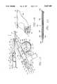
- FIG. 1is a side elevational view of a transurethral needle ablation device incorporating the present invention with a removable disposable needle assembly disposed therein.
- FIG. 2is a side elevational view of the needle assembly shown in FIG. 1.
- FIG. 3is a view of the needle assembly shown in FIG. 2 looking along the line 3--3 of FIG. 2.
- FIG. 4is a cross sectional view taken along the line 4--4 of FIG. 1.
- FIG. 5is an enlarged side elevational view of a portion of the device shown in FIG. 1 and particularly the bridge assembly with certain portions broken away.
- FIG. 6is an enlarged cross-sectional view of the distal extremity of the device shown in FIG. 1.
- FIG. 7is an enlarged plan view of the proximal extremity of the needle assembly shown in FIG. 3.
- FIG. 8is an elevational view taken along the lines 8--8 of FIG. 7.
- FIG. 9is a reduced side elevational view taken along the line 9--9 of FIG. 7.
- FIG. 10is a reduced side elevational view taken along the line 10--10 of FIG. 7.
- FIG. 11is a cross sectional view taken along the line 11--11 of FIG. 9.
- FIG. 12is a cross-sectional view taken along the line 12--12 of FIG. 10.
- FIG. 13is a side elevational view in section of another embodiment of a transurethral needle ablation device having a fixed insulation sleeve.
- FIG. 14is a side elevational view of the proximal portion of another embodiment of a transurethral needle ablation device incorporating the present invention.
- FIG. 15is an enlarged top plan view of the needle cartridge of the device shown in FIG. 14.
- FIG. 16is a view similar to that shown in FIG. 15 with the top cover plate and needle actuator removed.
- FIG. 18is a top plan view of the pull wire shown in FIG. 17.
- FIG. 19is a side elevational view of the distal extremity of the device shown in FIG. 14 with the needle assembly being deployed at an angle of 10°.
- FIG. 20is a view similar to FIG. 16 but showing the needle assembly being deployed at an angle of 85°.
- FIG. 21is an elevational view looking along the line 21--21 of FIG. 17.
- a sleeve of insulating materialis coaxially mounted on the radio frequency electrode and is also disposed in the passageway.
- the sleeveis disposed on the radio frequency electrode so that a preselected length of the radio frequency electrode extends beyond the sleeve and is exposed in the target volume of the prostate when the radio frequency electrode has been advanced into the target volume.
- the tissue of the prostate in the target volumesurrounds the preselected length of the radio frequency electrode.
- Meansis provided for supplying radio frequency energy the radio frequency electrode for causing ablation of the target volume.
- the transurethral needle ablation device 21 of the present inventionconsists of a bridge assembly 22 which has removably mounted thereon a sheath assembly 23 which is adapted to receive a conventional cystoscope or urethroscope 24 which extends through the bridge assembly 22 and through the sheath assembly 23.
- a disposable removable needle assembly 26which also can be characterized as a disposable removable cartridge assembly is removably seated within the bridge assembly 22 and extends through the sheath assembly 23.
- the bridge assembly 22consists of a bridge housing 31.
- the bridge housing 31can be formed by the suitable materials such as a polycarbonate and can be formed in two parts if desired to facilitate assembly.
- the bridge housing 31has been contoured so as to particularly adapted to fit with any human hand and is provided with forwardly facing curved recess 36 that is adapted to be engaged of by the index finger of the human hand with the remainder of the housing being adapted to be engaged by the palm of the hand.
- the sheath assembly 23includes a rigid sheath 41 of a suitable size as 21 French to serve as a rigid catheter-like delivery device having a suitable length as for example 25 centimeters.
- the sheath 41is formed of a suitable material such as stainless steel and is provided with a proximal and distal extremities 42 and 43 with an oval-shaped bore or lumen 44 extending from the proximal extremity 42 to the distal extremity 43.
- distal extremity 43is provided with a forwardly and upwardly extending curved surface 46 through which an upwardly inclined opening 47 extends and which is in communication and with the lumen bore 44.
- the sheath assembly 23includes a hub 51 mounted on the proximal extremity 42 of the sheath.
- the hub 51carries first and second stop cocks 52 on opposite sides of the same.
- a locking ring 54is rotatably mounted on the hub 51 and is provided with a handle 56 for locking the sheath assembly 23 onto the frontal extremity of the bridge housing 31 as shown in FIG. 1.
- the needle cartridge assembly 26which removably mounted in the bridge assembly 22 consists of first and second guide tube assemblies 71 and 72 which are slidably mounted in the passage way or bore 44 of the rigid sheath 41.
- the guide tube assemblies 71 and 72are substantially identical to each other and as shown in FIG. 3 are mounted side by side and are fastened together by suitable means such as solder connections 73.
- Each of the guide tube assemblies 71 and 72consists of an outer guide tube 74 (see FIG. 4) formed of a suitable material such as stainless steel having a 15 gauge wall thickness with an outside diameter of 0.072 inches and an inside diameter of 0.060 inches.
- the outer guide tube 74is provided with proximal and distal extremities 76 and 77.
- the proximal extremity 76is provided with the flange 78 (see FIG. 9).
- the distal extremity 77is provided with a plurality of longitudinally spaced apart circumferential extending L-shaped slots 79 as for example the last 1.5 centimeters of the guide tube 74.
- the slots 79subtend less than 360° and have a Suitable width as for example 0.012" and are spaced apart a suitable distance as for example 0.033".
- the slots 79are L-shaped and are provided with a toe or short leg length portion having a length of 0.010".
- the slots 79are not angularly offset and therefore provide a backbone or rib (not shown) extending longitudinally of the outer guide tube 74.
- the proximal extremity 76 of each outer guide tube 74is provided with a plurality of longitudinally spaced apart slots 81 (see FIG. 2).
- the slots 81can have a suitable width as for example 0.023 to 0.025" and can be spaced apart a suitable distance as for example 0.04".
- the slots 81subtend an angle less than 360° and by way of example can subtend an angle of 270° and be rotated by 120° with respect to each other.
- the slots 81extend over the suitable distance as for example 1.2 to 1.5" whereas the slots 79 can extend over a distance of approximately 0.5".
- a sleeve 82 formed of a heat shrinkable plasticis disposed over both guide tube assemblies 71 and 72 commencing at the distal extremity of the slots 81 and extending for approximately one inch there beyond. This sleeve 82 facilitates movement of the needle assembly into the bridge assembly 22 as hereinafter described.
- a pull element or pull ribbon 86 having a proximal extremityis provided within each of the outer guide tubes 74 and is secured to the distal extremity in a manner as disclosed in copending application Ser. No. 08/191,258.
- Each of the guide tube assemblies 71 and 72includes an insulation tube 91 of the type described in copending application Ser. No. 08/191,258 filed on Feb. 2, 1994.
- the insulation tube 91is slidably mounted in the outer guide tube 44 and is provided with proximal and distal extremities 92 and 93.
- a thermocouple 96is mounted in the distal extremity 93 of the insulation tube 91 in the manner described in copending application Ser. No. 08/191,258 and is coupled by conductors 97 extending to the proximal extremity within the guide tube 74.
- a needle electrode 101is slidably mounted in the insulation tube 91 and also is of the type described in the copending application Ser. No. 08/191,258 filed on Feb. 2, 1994.
- the needle electrode 101is formed of a suitable material such as a nickel titanium alloy having superelastic properties so that it will return to its original configuration after being bent. It is provided with a proximal extremity 102 and a distal extremity 103 in the form of a sharp needle-like point.
- a housing or cartridge 111is mounted on the proximal extremities of the guide tube assemblies 71 and 72 and forms a part of the needle cartridge assembly 26.
- the housing or cartridge 111consists of a body 112 which is rectangular in cross section and has a suitable width as for example 1/2" and a length of approximately 21/2".
- the cartridge or housing 111also consists of a cover plate 113 which is secured to the body 112 by suitable means such as screws 114.
- the forward or distal extremity of the cover plate 113is provided with a chamfer 116 to facilitate the introduction of the cartridge 111 into the bridge assembly 22 as hereinafter described.
- the cover plate 113is provided with an elongate slot 117 which has a scale of 118 shown in millimeters (see FIG.
- U-shaped cutouts 121are provided in opposite sides of the body 112 (see FIG. 2) for a purpose hereinafter described.
- An electrode connector 122is mounted on the body 112 and extends downwardly therefrom (see FIG. 9).
- the proximal extremities of the guide tube assemblies 71 and 72are disposed of within transversely spaced apart parallel slots 126 in the body 112 (see FIG. 7) and are clamped into place by a square brass plate 127 clamped into place by a screw 128.
- the lowermost distal extremity of the body 112is provided with the plurality of a downwardly extending transversely disposed teeth 123 which form a stationary rack 124. As it can be seen, this rack 123 is provided with a space 125 in which one tooth is missing for a reason hereinafter described.
- An additional rectangular plate 131(see FIG. 12) formed of a suitable material such as stainless steel is seated over the guide tube assemblies 71 and 72 and serves to hold them in place.
- the plate 131is clamped into place by the cover plate 113 secured to the body 112 by the screws 114.
- the plate 131is provided with a centrally disposed upwardly extending one-way breakoff pin 132 which extends through the slot 119 provided in the cover plate 113.
- the breakoff pin 132is provided with a recess 132a extending partially therethrough in a direction perpendicular to the axis of the pin 132 to permit the pin 132 to break off when it is pulled against the shoulders hereinafter described.
- the pin 132is formed of a metal such as brass which has good.
- the breakoff pin 132is mounted in the plate 131 by suitable means such as a press fit.
- the plate 131is provided with a recess 133 (see FIG. 12) which is adapted to frictionally receive a wedge 134 that is provided with a wedging surface 135 having a suitable angle as for example 5° which frictionally engages the proximal extremities of the pull ribbons 86 to frictionally clamp the same between the wedge 134 and the surface of the plate 131 forming the recess 133.
- the wedge 134 and the plate 131are formed of a suitable material such as stainless steel.
- the plate 131is provided with a pair of horizontally aligned bores 136 with which align with a corresponding pair of aligned bores 137 in the wedge 134.
- the outer guide tubes 74 of the guide tube assemblies 71 and 72have outwardly flared ends 138 on the proximal extremities 76 seated within the bores 136 and having the flared ends 138 retained in an annular recesses 139 provided in the plate 131 just slightly distal of the recess 133 in the plate 131.
- the insulation tubes 91 with the needle electrodes 101 thereinextend proximally through the bores 137 in the wedge 134.
- An insulation actuator 141 formed of a suitable plastic material such as a black polycarbonateis slidably mounted in a recess 142 provided in the body 112.
- the actuator 141is provided with an upstanding pin 143 which extends upwardly through the slot 117 in the cover plate 113.
- the insulator actuator 141is also provided with a pair of arcuate recesses 146 which are adapted to receive the flanged proximal extremities 147 of the stainless steel hypotubes 148 which form a part of the proximal extremity of the insulation tube 91 described in copending application Ser. No. 08/191,258 filed on Feb. 2, 1994.
- thermocouple conductors or wires 97 connected to the thermocouples 96also extend to the proximal extremity of the insulation tubes 91 and extend downwardly into the cable connector sleeve 122.
- the length of the thermocouple wires 97is sufficient to permit rectilinear movement of the insulator actuator 141 within a hole 149 provided in the body 112.
- a pair of spaced-apart elongate slots 150extend longitudinally of hte insulator actuator 141 and are used for the purpose hereinafter described.
- a needle actuator 151is slidably mounted within the cartridge 111 and is slidably mounted on the insulation actuator 141.
- the needle actuator 141is formed of a suitable plastic such as a clear polycarbonate to provide a color differentiation between the needle actuator 151 and the black carbonate forming the body 112 and the cover plate 113 in which the needle actuator travels.
- the needle actuator 151is provided with a pair of threaded aligned bores 152.
- Screw members 153are provided with enlarged cylindrical portion 154 which are adapted to seat against annular shoulders 156 provided in the needle actuator 151.
- the enlarged cylindrical portion 154is provided with a slot 157 which can be used in conjunction with the tool (not shown) for adjustably positioning the screw member 153 in the bore 152.
- the screw members 153are also provided with thin wall cylindrical extensions 158 having bores 159 extending therethrough and extending through the enlarged cylindrical portions 154.
- the needle electrodes 101extend through the bores 159 and have therein proximal extremities frictionally clamped within the cylindrical extension 158 by crimping the cylindrical extension 158 therein. It can be seen by rotating the screw members 153 within the threaded bores 152, the longitudinal positions of the needle electrodes 101 relative to the insulation tubes 91 may be adjusted for purposes hereinafter described.
- the cylinkdrical extension 158is connected to insulated leads 160 that are soldered thereto and extend through the slots 150 in the insulator actuator and through the hole 149 in the electrical connector 122.
- the needle actuator 151is provided with an upstanding protrusion 161 (see FIG. 9) which extends upwardly through the slot 117 and is provided with a threaded bore 162 therein which lies in a plane parallel to the plane of the cover 113.
- An adjustment screw 163having an knurled knob 164 on the same is threaded into the threaded bore 163.
- the knob 164is adapted to engage the upstanding pin 143 extending upwardly through the slot 117 as hereinafter described.
- the needle actuator 151is provided with a spring finger 166 which is formed integral with the needle actuator and which is provided by a slot 167 formed in the needle actuator.
- the spring finger 166is provided with an upstanding portion 168 which carries an outwardly extending portion 169.
- the portion 169is yieldably urged outwardly by the spring finger 166 and is adapted to releasably seat in a rectangular recess 171 provided in the cover plate 113.
- a pin 176 formed of a suitable material such as plasticis mounted on the spring finger 166 and extends outwardly therefrom.
- the pin 176is provided with an outwardly extending flange 177.
- a knob 179which is generally rectangular in cross section is rotatably mounted on the pin 176 and has a bore 181 therein which is adapted to fit over the pin 176.
- a shoulder 182is provided within the bore and is adapted to be pushed over and engage the flange 177 provided on the pin 176.
- the knob 179because it is rectangular in cross section (see FIG.
- the knob 179has a dimension in the other direction of its rectangular cross section which is greater than the width of the slot 121 so that when the knob is rotated by 90° it cannot be pushed inwardly because it has portions which extend beyond the slot 121 and thereby preventing release of the protrusion or outwardly extending portion 169 of the spring finger 166.
- a pin 186(see FIG. 8) is mounted on the needle actuator 151 on the side opposite the spring finger 166. It extends outwardly through the cutout 121 provided on the opposite side of the body 112.
- the pin 186is provided with an annular recess 187 and has a rounded conical protrusion 188.
- An outwardly extending pin 191is provided on a boss 192 on the body 112.
- Yieldable elastic means 196 in the form of a latex rubber band 196has an inwardly extending protrusion 197 therein which is provided with a bore 198 permitting the protrusion to be fitted over the pin 191 (see FIG. 7).
- the rubber band 196is provided with an elongate slot 199 which opens into a larger opening 201 which receives the pin 186 and permits the rubber band 196 to seat within the annular recess 187.
- the proximal end of the rubber band 196is provided with an outwardly extending protrusion 203 which is adapted to be engaged by two fingers of the human hand to facilitate loading of the rubber band 196 onto the pin 186.
- the pin 186 as shown in FIG. 7is in the loaded position with other positions of the pin 186 being shown in dotted lines for the "operating" position and the "fired” position, respectively, looking from left to right in FIG. 7.
- a U-shaped enclosure 206(see FIG. 7) is secured to the side of the body 112 and is provided with a U-shaped recess 207 in which the rubber band 196 is disposed.
- the bridge assembly 22consists of a housing 211 formed of a suitable material such as black polycarbonate. If desired, the housing 211 can be formed of two parts which can be fastened together by suitable means such as screws or ultrasonic bonding.
- a large spur gear 212is rotatably mounted within the housing 211 and is fixed to a shaft 213 by a screw 214 engaging a flat 215.
- the shaft 213extends through holes (not shown) provided in opposite sides of the housing 211 and has a rectangular knob 217 mounted thereon on one side of the housing 211 and secured thereto by suitable means such as a screw 218.
- Meansis provided for limiting rotation of the spur gear 212 between a limited angle, as for example an angle of 90°, and consists of a pin 221 carried by the housing 211 which extends through an arcuate slot 222 provided in the spur gear 212.
- Meansis provided for yieldably retaining the spur gear 212 in various positions as determined by the spacing of the teeth 226 of the spur gear 212 and consists of a roller pin 227 (see FIG. 5) mounted in a recess 228 in the housing 211 and yieldably urged into recesses between the gear teeth 276 and into engagement with the gear teeth 226 by a rectangular rubber member 229 disposed in a slot 231 in the housing 211 and yieldably urging the roller pin 227 in a direction toward the teeth 226 of the spur gear 212.
- a spring metal reinforcing strip 232is placed in front of the rubber member 229 and engages the pin 227.
- one of the teeth 226 of the spur gear 213is missing to permit entry of the stationary rack 124 carried by the body 112 when the cartridge 111 is introduced into a rectangular recess 236 provided in the body which opens distally into a tapered passageway 237.
- the tapered passageway 237opens into an oval shaped passageway 238 through which the guide tube assemblies 71 and 72 are adapted to extend.
- Meansis provided in the housing 211 for receiving the breakoff pin 132 and consists of a spring clip 241 (see FIG. 7) formed of a suitable material such as stainless steel which is seated within a recess 42 provided in the housing 211.
- the spring clip 241is provided with two proximally extending spring fingers 243 carried by a base 244.
- the spring fingers 243are spaced apart and parallel and are provided with cam surfaces 246 which are adapted to be engaged by the breakoff pin 132 as the cartridge 111 is advanced into the recess 236.
- the fingers 243face proximally into a recess 248 in the housing 211 which is adapted to receive the breakoff pin 132.
- the teeth 226 on the spur gear 212engage the rack teeth 123 carried by the cartridge.
- the one-way breakoff pin 132cams the fingers 243 outwardly from each other until the breakoff pin 132 clears the camming surfaces 246 permitting the spring fingers 243 to snap back into their normal positions but preventing the breakoff pin from re-exiting through the fingers 243 because of engagement with shoulders 247 provided on the fingers 243.
- the bridge assembly 22also includes a bore 251 (see FIG. 5) which receives the optical tube 57 of the cystoscope 24.
- the bore 251opens proximally into a larger bore 252 which opens into a still larger bore 253 provided in the housing adapted to receive the cystoscope 24.
- An O-ring 256is mounted in the housing and forms a fluid-tight seal with the cystoscope 24.
- the housing 211is also provided with a small hole 257 overlying the bore 252 which is adapted to receive a registration pin 258 carried by the cystoscope 24.
- Another O-ring 261is mounted within the housing 211 and is seated within an annular recess 262 provided in the housing 211.
- the O-ring 261releasably engages the optical tube 57 of the cystoscope 24 and also releasably engages the guide tube assemblies 71 and 72 to form a fluid-tight seal therewith.
- transurethral needle ablation device 21 of the present inventionOperation and use of the transurethral needle ablation device 21 of the present invention and the method for using the same for treatment of the prostate may now be briefly described as follows. Let it be assumed that the physician has previously examined the prostate with a conventional cystoscope or urethroscope and has determined that the patient has an enlarged prostate which requires treatment by use of RF ablation by utilizing the device and method of the present invention. Since the bridge assembly 22 is a reusable device, let it be assumed that the bridge assembly 22 has been properly sterilized as has the sheath assembly 23 and that the sheath assembly 23 has been mounted on the bridge assembly 22. A conventional cystoscope 24 is inserted into the bridge assembly 22. The fitting 58 is connected to a conventional light source 59 (see FIG. 1).
- the physiciannext removes a disposable needle cartridge assembly 26 from the packaging as shipped by the manufacturer.
- the physicianadjusts the knob 164 using the scale 118 and determines the amount that the needle electrode 101 is to extend beyond the insulation tube 91 during an ablation procedure.
- the physicianhas determined that a needle length of 7 millimeters is appropriate.
- the knob 164 of the needle adjustment screw 163is then adjusted with respect to the scale 118 so that the knob is in registration with the 7 millimeter dimension of the scale 118.
- the trigger mechanismconsisting of yieldable elastic means 196 is then set or cocked by pulling rearwardly or proximally on the protrusion 203 until the outwardly extending portion 169 snaps into the recess 171 and rotating the knob 179 so that it is in a vertical position preventing it from being depressed into the cut-out 121.
- the needle cartridge assembly 26can then be connected to a suitable source of radiofrequency energy, as for example a control console 276 of a type well known to one skilled in the art by suitable cabling 277 to the connector sleeve 122.
- the needle cartridge assembly 26can then be inserted into the bridge assembly 22 by inserting the guide tube assemblies 71 and 72 through the rectangular recess 236 and then into the tapered passageway 237 and into the oval-shaped passageway 238 past the O-ring 262 and into the sheath assembly 23 followed by the cartridge 111.
- the cartridge 111is advanced until the forward extremity of the cartridge is disposed in the space in which the tooth 226 is missing.
- the assembled device 21is now ready for use.
- the patienthas been prepared by having the urethra in the penis filled with an antiseptic gel.
- the rigid sheath 41is then introduced into the urethra under view through the eye piece 56 and advanced into the urethra until the distal extremity of the rigid sheath 41 is disposed within the bladder of the patient.
- a saline solutionis introduced into the urethra simultaneously so that the antiseptic gel which is water soluble is washed away and a clean field of view of provided in front of the optical tube 51 of the cystoscope 24 so that the physician can view the progress of the rigid sheath 41 as it is being introduced into the urethra.
- the physicianwithdraws the rigid sheath 41 until the physician is sure that the distal extremity of the sheath is disposed within the patient's prostate that surrounds the urethra immediately proximal of the bladder.
- the physicianthen rotates the bridge assembly 22 using one hand to grasp the housing 111 to rotate the rigid sheath 41 until the distal extremity is disposed at the proper angle within the prostate so that radiofrequency ablation can be carried out in the desired lobe of the prostate.
- the physicianuses the other hand to grasp the knob 217 to move it from a horizontal position to a generally vertical position to thereby cause the spur gear 212 to rotate in a clockwise position as viewed in FIG. 5 to cause the teeth 216 thereon to engage the teeth 123 of the stationary rack on the cartridge 111 to move the cartridge 111 forwardly.
- the one-way breakoff pin 132is advanced between the camming surfaces 246 to spread apart the spring fingers 243. This movement continues until the cam surfaces 246 are cleared permitting the spring fingers 243 to snap into their normal positions and to hold the breakoff 132 pin in place so that it cannot be retracted without breaking off the breakoff pin.
- the pull ribbons 86are pulled to cause the outer distal extremities of the guide tube assemblies 71 and 72 to be bent so that they extend essentially at right angles with respect to the longitudinal axis of the sheath 41 by engagement of the breakoff pin 132 carried by the plate 131 with the bridge housing 211.
- the distal extremities of the guide tube assemblies 71 and 72are being deployed at a suitable orientation, as for example at an 85° angle with respect to the longitudinal axis of the sheath 41 separated at a suitable angle, as for example 30° as disclosed in co-pending application Ser. No. 08/191,258 filed Feb. 2, 1994.
- the physicianby looking through the cystoscope 24 can observe this deployment.
- the physiciancan release the trigger mechanism hereinbefore described by rotating the knob 179 through 90° so that its longer face lies in horizontal plane parallel with the plane of the cutouts 121.
- Pushing inwardly on the knob 179causes the spring finger 166 to be depressed to cause the outwardly extending portion 169 to be released from the recess 171 permitting the needle actuator 151 to be urged forwardly causing the needle electrodes 101 carried thereby to be rapidly urged through the urethral wall so that tenting of the urethral wall is minimized and then advanced into the prostate for the predetermined distance set by the knob 164.
- the knob 164was set for a distance of 7 millimeters, which means that the needle electrodes 101 will be advanced by that distance until the knob 164 strikes the upstanding pin 143 to thereafter carry with it the insulation actuator 141.
- the needle actuator 141 and the insulation actuator 141then move in unison for another predetermined distance, which for example can be set for a distance ranging from 5 to 8 millimeters and preferably a distance of 6-7 millimeters.
- the insulation tubes 91are also rapidly urged through the urethral wall and extend through the urethral wall for a distance of approximately 6 to 7 millimeters with the needle electrodes being further advanced by the same amount so that the distal extremities of the needle electrode exposed outside of the insulation tube are exposed for a distance of approximately 7 millimeters.
- the needle electrodes 101are first moved into the prostate and are followed by the insulation tubes 91.
- radiofrequency energyis applied from the control console 276 to the radiofrequency electrodes for an appropriate period of time as for example 2 to 5 minutes.
- Radiofrequency ablationis carried out in the manner described in co-pending application Ser. No. 08/191,258 filed Feb. 2, 1994 so that the urethral wall is at all times protected from radiofrequency ablation. This is accomplished by having insulation tubes 91 extend a suitable distance into the prostate, as for example the 7 millimeters hereinbefore described, to ensure that a protected region is provided in the prostate immediately adjacent the urethral wall to protect the urethral wall.
- the knob 179is grasped and retracted to bring back with it the needle actuator 151. Movement of the needle actuator 151 causes the needle electrodes 101 to be retracted until their distal extremities are retracted slightly within the distal extremity of the insulation tubes 91 as for example 0.010". Thereafter continued retraction of the needle actuator 151 causes the insulation actuator 41 to follow and to move it back to the load position hereinbefore described. Thereafter, the distal extremities of the guide tube assemblies 71 and 72 are straightened by returning the knob 217 to a horizontal position from the dotted line position shown in FIG. 1.
- the physicianafter retraction of the needle actuator 151 and insulation actuator 151 and straightening of the distal extremity of the guide tube assemblies 71 and 72, can rotate the rigid sheath 41 by a suitable angle as for example 60° after which the same procedure can be completed.
- the knob 217is rotated until it is in the horizontal position causing the distal extremities of the guide tube assemblies 71 and 72 to extend at substantially right angle directions with respect to the longitudinal axis of the rigid sheath 41.
- the knob 179can be rotated so that its long surface is parallel to the cutout 121.
- the device 21can be removed first by grasping the knob 179 and retracting the needle electrodes 101 followed by the insulation tubes 96 into the outer guide tubes 74 with the needle electrodes 101 always extending for a slight distance beyond the distal extremity of the insulation tubes 91. Thereafter, the distal extremities of the guide tube assemblies 71 and 72 can be straightened by bringing the knob 217 back to a horizontal position. Thereafter, the entire device 21 can be removed from the urethra.
- the needle cartridge assembly 26can be removed from the bridge assembly 22 by pulling the cartridge forwardly to bring the breakoff pin 132 into engagement with the shoulders 247 to cause the same to break off. The needle cartridge assembly 26 can then be disposed of. Since the breakoff pin has been broken off, the needle cartridge assembly 26 cannot be reused because there is no pin available for causing bending of the distal extremity of the guide tube assemblies 71 and 72.
- the needle cartridge assembly 26 shown in FIGS. 1-12has been constructed in a manner so that it is relatively simple and relatively inexpensive whereby it can be disposed of after a one-time use.
- an insulated needle electrode 281which can be utilized in the guide tube assembly 71 and 72 is shown FIG. 13 and as shown therein consists of a needle electrode 282 formed of a suitable metal as for example a nickel titanium alloy or a flexible needle which can serve as a conductor that is provided with a pointed or sharpened tip 283.
- a fixed insulated sleeve 286is coaxially disposed on the needle electrode 282 so as to leave a predetermined length of the electrode 282 exposed as for example a length of 7 millimeters.
- the insulating sleeve 286can be formed in a suitable manner such as by dip-coating by immersing the same in a liquid insulating coating material and permitting the same to harden onto the exterior surface of the needle 282.
- the coaxial insulating layer 282can be formed of a suitable heat shrinkable plastic which can serve as an insulating material.
- the insulating materialcan be formed of a suitable plastic material such as polyimide or Nylon.
- thermocouple 289is embedded in the coaxial insulation 286 near the sharpened tip 287 as shown and is connected by conductors 289 which lead to the proximal extremity of the insulated needle electrode 281.
- the use of the insulated needle electrode 281is very similar to that hereinbefore described in connection with the needle electrodes hereinbefore described with exception that the needle electrode 281 will not be advanced out of the outer guide tube 74 until the distal extremity of the outer guide tube 74 is disposed in the appropriate position in the urethra after which the needle electrode 281 can be advanced and retracted to perform ablation procedures in the manner hereinbefore described with the coaxial insulation being disposed in the urethral wall to protect the urethral wall during ablation.
- FIGS. 14-21Another transurethral needle ablation device 301 is shown in FIGS. 14-21 incorporating another embodiment of the invention. As shown therein, it consists of a bridge assembly 302 which is adapted to have mounted thereon a removable sheath assembly 23 (not shown) of the type hereinbefore described and which has mounted therein a cystoscope or urethroscope 24 of a conventional type as hereinbefore described.
- a needle cartridge assembly 306is removably mounted in the bridge assembly 302.
- the bridge assembly 302consists of a bridge housing 311 similar to the bridge housing 31 hereinbefore described.
- the bridge housing 311is formed of a suitable material such as a black polycarbonate. It is provided with a first passage 312 which is adapted to receive the cystoscope or urethroscope 24 as shown in FIG. 14.
- the passage 312can be square in cross-section and overlies another passage 313 which can be oval-shaped in cross-section with the longest axis of the oval-shaped opening lying in a horizontal plane parallel to the passage 312.
- the bridge assembly 302includes a bridge gear 316 which includes an integral shaft 317 rotatably mounted in the bridge housing as shown.
- the gear 316is generally cylindrical and is provided with a plurality of teeth 318 extending outwardly from the circumferential surface of the gear 316.
- the teeth 318extend over a predetermined sector of the gear 316 as for example through an angle of 110° with two of the teeth 318 being removed after the first tooth as viewed in the most clockwise position in FIG. 14 to facilitate engagement with the needle cartridge assembly 306 as hereinafter described.
- the gear 316is provided with an outwardly extending handle 321 formed integral therewith which extends through an elongate arcuate slot 322 provided in the bridge housing 311 to permit movement of the handle 321 and the gear 316 carried thereby through a suitable angle as for example 90°.
- the handle 321is utilized for moving the needle cartridge assembly 306 between an extreme forward position and a rearward position.
- the handle 321is shown in solid lines in FIG. 14 with the needle cartridge assembly 306 in the rearmost position.
- the handle 321is shown in dotted lines when the needle cartridge assembly 306 has been moved to an extreme forward position.
- Toggle spring meansis provided for retaining the handle 321 in either the forward or rearward positions and consists of a spring 326 formed from a single piece of spring wire which has an intermediate portion wound into two loops 327 and having one leg 328 engaging a pin 329 provided on the gear 316 and having another leg 331 engaging a pin 332 mounted in the bridge housing 311 (see FIG. 14).
- the toggle spring 326toggles over center as shown in dotted lines in FIG. 14 to retain the handle 321 in the desired position.
- the needle cartridge assembly 306consists of a cartridge or housing 341 formed of a suitable material such as a black polycarbonate.
- the housing 341consists of a body 342 and a cover plate 343.
- the cover plate 343is secured to the body 342 by suitable means such as screws (not shown).
- a female electrical connector assembly 346is mounted in the body 342 and can be of the type utilized in the telephone industry for making electrical connections.
- the body 342is provided with a rack 351 having a plurality of spaced-apart teeth 352 that are adapted to be engaged by the teeth 318 of the gear 316 of the bridge assembly 302.
- the third tooth 352 counting from the right as viewed in FIG. 14is removed to make possible the mating of the needle cartridge assembly 306 with the bridge assembly 302 and to permit the teeth 318 of the gear 316 to mate with the teeth 352 of the rack 351 and thereafter to permit movement of the needle cartridge assembly 306 between its forwardmost and rearwardmost positions.
- the body 342 of the cartridge housing 341is provided with an upwardly facing rectangular recess 356 in which an insulation actuator 357 is slidably mounted for movement between first and second positions.
- the actuator 357is provided with a pair of elongate slots 358 at the rearmost extremity thereof. It is also provided with a central viewing hole 359 forward of the slots 358 and an upwardly extending post 361. It is also provided with a pair of slots 362 extending on opposite sides of the post 361 which are adapted to receive the flanged proximity extremities of the insulation tubes 91.
- a pair of holes 363are provided on opposite sides of the post 361 and are adapted to have the thermocouple wires 97 pass therethrough to be connected to the connector assembly 346.
- the insulation actuator 357is provided with a pair of upstanding spaced-apart protrusions 364. The upstanding post 361 is positioned so that it can extend and travel in a slot 366 provided in the cover plate 343.
- a pull ribbon plate 367 formed of a suitable material such as stainless steelis slidably mounted in the recess 366 and is provided with ears 368 that protrude outwardly sidewise of the body 342 through elongate slots 369 provided on opposite sides of the cartridge housing 341.
- the plate 367is provided with a longitudinally extending slot 371 which receives an upwardly extending protrusion 372 formed integral with the body 342 and extending upwardly into the recess 366.
- the slot 371 and the protrusion 372cooperatively serve to guide the plate 367 between its forwardmost and rearwardmost positions within the recess 366.
- the body 342is provided with a pair of longitudinally extending slots 373 which underlie the plate 367 and which receive the insulation tubes 91 with the electrodes 101.
- the slots 373extend proximally or rearwardly from the proximal extremities 76 of the outer guide tubes 74 and which are clamped into the front or distal extremity of the cartridge housing 341 by a plate 376 held in place by a screw 377 threaded into the body 342.
- Each of the guide tube assemblies 71 and 72is provided with a pull ribbon 381 which corresponds to the pull ribbons 86 hereinbefore described.
- the pull ribbon 381 as shown in FIG. 17is in the form of an elongate stainless steel ribbon which is provided with T-shaped extremities 382 and 383.
- the pull ribbons 381extend proximally from the proximal extremity 76 of the outer guide tubes 74 and extend through the slots 384 provided on opposite sides of the slot 371 in the plate 367 and have the T-shaped portions 382 engage an upstanding wall 386 formed on the plate 367.
- the insulation tubes 91 and the electrodes 101 along with the thermocouple wires 97extend proximally with the insulation wires 97 passing through the holes 363 and with the flanged extremities of the insulation tubes 91 being fastened in the insulation actuator 357.
- the proximal extremities of the electrodes 101extend proximally and are fastened into a needle actuator 391 formed of a suitable material such as a black carbonate.
- the needle actuator 391is provided with a body 392 which is slidably mounted above the insulator actuator 357 and which has an upwardly extending protrusion 393 that extends through the slot 366 in the top cover plate 343.
- the body 392is provided with bores 396.
- the distal extremities of the needle electrodes 101are retained within the bores 396 by an adjustment screw insert 397 secured to the proximal extremity 102 of the needle electrodes 101 permitting the needle electrode 101 to be adjusted axially of the insulation tube 91 in which it is disposed.
- a sidewise extending trigger handle 401is formed integral with the body 392 of the needle actuator 391 and is configured to be engaged by the thumb of a human hand.
- the body 302is provided with an inwardly extending recess 402 (see FIG. 16) to permit the handle 401 to be depressed inwardly by force of the thumb against the yieldable force of the plastic to cause an upwardly extending protrusion 403 to be pushed out of a slot 404 provided in the side of the top cover plate 343 so that the needle actuator 391 can be released and pushed forwardly or distally when desired.
- Another upstanding handle 406is provided as a part of the needle actuator 391 and is formed with a curved surface 407 to fit a finger of the human hand and is secured to the upstanding protrusion 403 by suitable means such as a screw 408.
- a needle adjustment screw 163 having a knob 164 of the type hereinbefore describedis mounted in the upwardly extending protrusion 403.
- FIG. 17there is shown the guide tube assembly 72.
- the pull ribbon 381is mounted therein and has its distal tee-shaped portion 383 mounted in a slot 384 in the outer guide tube 74 just proximal of a nipple 411.
- the nipple 411is formed of a suitable material such as stainless steel and is bonded to the distal extremity of the outer guide tube 74 by suitable means such as an adhesive.
- the nipple 411is provided with a rounded forward extremity 412 as shown in FIG. 17 to provide a forward extremity for each of the guide tube assemblies 71 and 72 which can be readily guided through the urethra without damaging the urethra.
- the needle electrode 101 during this movementis recessed a suitable amount as for example 0.010" to prevent the sharpened tip 103 of the needle electrode from engaging the urethral wall.
- transurethral needle ablation device 301Operation and use of the embodiment of the transurethral needle ablation device 301 is very similar to that hereinbefore described.
- the bridge 301is utilized and a sheath assembly 23 of the type hereinbefore described is mounted on the sheath assembly.
- a cystoscope 24is also mounted in the bridge 301 and in the sheath assembly 23 and extends through the sheath assembly 23.
- the removable needle cartridge assembly 306is then taken and its distal extremity introduced into the bridge 301 through the passage 313 and into the sheath assembly 23.
- the knob 164is adjusted to determine the amount that the needle electrode is to extend beyond the insulation tube 91 during an ablation procedure.
- the needle cartridge assembly 306is connected to a control console 276 of the type hereinbefore described.
- the patientis prepared for the procedure in the manner hereinbefore described and the sheath 41 is introduced into the urethra and has its distal extremity disposed so that it lies in the urethra in the region within the patient's prostate surrounding the urethra.
- the device 301is then rotated to the desired position within the urethra by using one hand. For example, it can be rotated so that the needle electrodes 101 wil enter the median lobe of the prostate.
- the other handgrasps the handle 321 to cause rotational movement of the gear 316 to cause its teeth 318 to engage the teeth 352 of the rack 351 to cause advancement of the needle cartridge assembly 306 against the yieldable force of the toggle spring 326 to cause the distal extremities of the outer guide tubes 74 of the guide tube assemblies 71 and 72 to be advanced distally and at the same time to cause the distal extremities to be bent sidewise with respect to the longitudinal axis of the sheath 41 as tensioning forces are applied by the pull ribbon 381 as shown in FIG. 19. If, by way of example, it is desired to treat the median lobe of the prostate, a relatively small angle is utilized with respect to the longitudinal axis of the sheath 41, as for example an angle of 10° as shown in FIG. 18.
- the handle 401can be pressed inwardly to cause the protrusion 403 to be released from the slot 404. This permits the physician undertaking the procedure to have a finger of the hand engage the upstanding handle 406 and to advance the needle actuator 391 to first cause the needle electrode 101 to be advanced and thereafter as the adjustment knob 164 engages the upstanding post 361 to cause forward advancement of the insulation ctuator 357.
- the needle electrodes 101 and the insulation sleeves 91are moved in unison as the handle 406 is pushed forwardly to cause the needle electrodes 101 and the insulation sleeves 91 carried thereby to penetrate the urethral wall with a minimum of tenting and thereafter enter the prostate with the needle electrodes 101 exposed a predetermined amount within the median lobe of the prostate and with the insulation tubes extending through the urethral wall.
- Radiofrequency ablationcan thereafter be carried out in the manner hereinbefore described with the urethral wall being protected by the insulation sleeves 91.
- the surface 407 of the handle 406can be engaged by a finger of the hand and the needle actuator 391 retracted causing the needle electrodes 101 to be first retracted and followed by the insulation sleeves 91 when the needle actuator 391 engages the upstanding protrusions 364 provided on the insulator actuator 357 to cause the insulator actuator 357 to be thereafter retracted in unison to withdraw the needle electrodes 101 and insulation sleeves 91 into the confines of the outer guide tubes 74 so that the sharp tips 103 of the needle electrodes 101 are recessed in the outer guide tubes 74.
- the device 301can then be rotated into another location as desired by the physician as hereinbefore described.
- itmay be desired to perform radiofrequency ablation in one or both of the side or lateral lobes of the prostate in which it is desired to enter the prostate at substantially right angles, as for example of 85° with respect to the longitudinal axis of the sheath 43 as shown in FIG. 20.
- Thiscan be readily accomplished in the manner hereinbefore described by operation of the handle 321 and moving it to the extreme dotted-line position shown in FIG. 14 to cause the distal extremity to be bent through the approximate 85° shown in FIG. 20.
- the needle electrodes 101 and insulation tubes 91are then rapidly advanced through the urethral wall and into the prostate as hereinbefore described and thereafter radiofrequency ablation carried out.
- the distal extremities of the needle electrodes 101are deployed sidewise from the longitudinal axis of the sheath 43 and typically subtend at an angle which is less than an acute angle, as for example 40° as shown in FIG. 21 during radiofrequency ablation.
- the distal extremities of the needles 101 as well as the distal extremities of the insulation tubes 91can be observed by the cystoscope during positioning of the same.
- the electrodes 101 and the insulation tubes 91can be withdrawn in the manner hereinbefore described so that the distal extremities of the electrodes 101 are disposed within the outer guide tubes 74.
- the handle 321can then be moved from the dotted-line position to the solid-line position going over center for the toggle spring 326 to cause the distal extremities of the guide, tubes 74 to be straightened and to permit the same to be retracted into the sheath 43 after which the device 301 can be withdrawn from the urethra.
Landscapes
- Health & Medical Sciences (AREA)
- Life Sciences & Earth Sciences (AREA)
- Engineering & Computer Science (AREA)
- Biomedical Technology (AREA)
- Public Health (AREA)
- Veterinary Medicine (AREA)
- Surgery (AREA)
- Animal Behavior & Ethology (AREA)
- General Health & Medical Sciences (AREA)
- Nuclear Medicine, Radiotherapy & Molecular Imaging (AREA)
- Heart & Thoracic Surgery (AREA)
- Medical Informatics (AREA)
- Molecular Biology (AREA)
- Pathology (AREA)
- Otolaryngology (AREA)
- Radiology & Medical Imaging (AREA)
- Physics & Mathematics (AREA)
- Plasma & Fusion (AREA)
- Biodiversity & Conservation Biology (AREA)
- Electromagnetism (AREA)
- Biophysics (AREA)
- Pulmonology (AREA)
- Anesthesiology (AREA)
- Hematology (AREA)
- Surgical Instruments (AREA)
Abstract
Description
Claims (31)
Priority Applications (4)
| Application Number | Priority Date | Filing Date | Title |
|---|---|---|---|
| US08/377,645US5667488A (en) | 1992-08-12 | 1995-01-25 | Transurethral needle ablation device and method for the treatment of the prostate |
| AU47650/96AAU4765096A (en) | 1995-01-25 | 1996-01-24 | Transurethral needle ablation device and method for the treatment of the prostate |
| PCT/US1996/000912WO1996022742A1 (en) | 1995-01-25 | 1996-01-24 | Transurethral needle ablation device and method for the treatment of the prostate |
| US08/790,094US5807309A (en) | 1992-08-12 | 1997-01-29 | Transurethral needle ablation device and method for the treatment of the prostate |
Applications Claiming Priority (7)
| Application Number | Priority Date | Filing Date | Title |
|---|---|---|---|
| US92963892A | 1992-08-12 | 1992-08-12 | |
| US08/012,370US5370675A (en) | 1992-08-12 | 1993-02-02 | Medical probe device and method |
| US08/061,647US5421819A (en) | 1992-08-12 | 1993-05-13 | Medical probe device |
| US08/062,364US5435805A (en) | 1992-08-12 | 1993-05-13 | Medical probe device with optical viewing capability |
| US08/109,190US5409453A (en) | 1992-08-12 | 1993-08-19 | Steerable medical probe with stylets |
| US08/191,258US5549644A (en) | 1992-08-12 | 1994-02-02 | Transurethral needle ablation device with cystoscope and method for treatment of the prostate |
| US08/377,645US5667488A (en) | 1992-08-12 | 1995-01-25 | Transurethral needle ablation device and method for the treatment of the prostate |
Related Parent Applications (1)
| Application Number | Title | Priority Date | Filing Date |
|---|---|---|---|
| US08/191,258Continuation-In-PartUS5549644A (en) | 1992-08-12 | 1994-02-02 | Transurethral needle ablation device with cystoscope and method for treatment of the prostate |
Related Child Applications (1)
| Application Number | Title | Priority Date | Filing Date |
|---|---|---|---|
| US08/790,094ContinuationUS5807309A (en) | 1992-08-12 | 1997-01-29 | Transurethral needle ablation device and method for the treatment of the prostate |
Publications (1)
| Publication Number | Publication Date |
|---|---|
| US5667488Atrue US5667488A (en) | 1997-09-16 |
Family
ID=23489964
Family Applications (1)
| Application Number | Title | Priority Date | Filing Date |
|---|---|---|---|
| US08/377,645Expired - LifetimeUS5667488A (en) | 1992-08-12 | 1995-01-25 | Transurethral needle ablation device and method for the treatment of the prostate |
Country Status (3)
| Country | Link |
|---|---|
| US (1) | US5667488A (en) |
| AU (1) | AU4765096A (en) |
| WO (1) | WO1996022742A1 (en) |
Cited By (153)
| Publication number | Priority date | Publication date | Assignee | Title |
|---|---|---|---|---|
| WO1998046150A1 (en)* | 1997-04-11 | 1998-10-22 | Vidamed, Inc. | Transurethral needle ablation device with replaceable stylet cartridge |
| US5855567A (en)* | 1996-08-22 | 1999-01-05 | Scimed Life Systems, Inc. | Catheter management system |
| US5921954A (en)* | 1996-07-10 | 1999-07-13 | Mohr, Jr.; Lawrence G. | Treating aneurysms by applying hardening/softening agents to hardenable/softenable substances |
| WO1999045855A1 (en) | 1998-03-09 | 1999-09-16 | Cardiofocus, Inc. | Thermal treatment device including expansion element |
| US6035238A (en)* | 1997-08-13 | 2000-03-07 | Surx, Inc. | Noninvasive devices, methods, and systems for shrinking of tissues |
| US6081749A (en)* | 1997-08-13 | 2000-06-27 | Surx, Inc. | Noninvasive devices, methods, and systems for shrinking of tissues |
| US6221071B1 (en) | 1999-06-04 | 2001-04-24 | Scimed Life Systems, Inc. | Rapid electrode deployment |
| US6238389B1 (en)* | 1997-09-30 | 2001-05-29 | Boston Scientific Corporation | Deflectable interstitial ablation device |
| US6338726B1 (en) | 1997-02-06 | 2002-01-15 | Vidacare, Inc. | Treating urinary and other body strictures |
| WO2002028303A1 (en)* | 2000-10-05 | 2002-04-11 | Vidamed, Inc. | Bipolar ablation apparatus and method |
| US6391027B1 (en)* | 1996-07-04 | 2002-05-21 | Erbe Elektromedizin Gmbh | Gas-aided, axially displaceable surgical electrode |
| US6394949B1 (en) | 1998-10-05 | 2002-05-28 | Scimed Life Systems, Inc. | Large area thermal ablation |
| US6480746B1 (en) | 1997-08-13 | 2002-11-12 | Surx, Inc. | Noninvasive devices, methods, and systems for shrinking of tissues |
| US6526320B2 (en)* | 1998-11-16 | 2003-02-25 | United States Surgical Corporation | Apparatus for thermal treatment of tissue |
| US6546934B1 (en) | 1996-11-08 | 2003-04-15 | Surx, Inc. | Noninvasive devices and methods for shrinking of tissues |
| US6607529B1 (en)* | 1995-06-19 | 2003-08-19 | Medtronic Vidamed, Inc. | Electrosurgical device |
| US6613047B2 (en)* | 1994-06-24 | 2003-09-02 | Curon Medical, Inc. | Apparatus to treat esophageal sphincters |
| US20030178032A1 (en)* | 1997-08-13 | 2003-09-25 | Surx, Inc. | Noninvasive devices, methods, and systems for shrinking of tissues |
| US20030199953A1 (en)* | 2002-04-22 | 2003-10-23 | Stolz Brian T. | Implantable lead with coplanar contact coupling |
| US20030199952A1 (en)* | 2002-04-22 | 2003-10-23 | Stolz Brian T. | Implantable lead with improved distal tip |
| US20040024440A1 (en)* | 2002-04-22 | 2004-02-05 | Cole Mary Lee | Implantable lead with isolated contact coupling |
| US6751507B2 (en) | 1999-09-10 | 2004-06-15 | Solarant Medical, Inc. | Endopelvic fascia treatment for incontinence |
| US20040267336A1 (en)* | 1996-11-08 | 2004-12-30 | Solarant Medical, Inc. | Energy induced bulking and buttressing of tissues for incontinence |
| US20050245924A1 (en)* | 2004-04-30 | 2005-11-03 | Medtronic, Inc. | Ion eluting tuna device |
| US20060142695A1 (en)* | 2004-12-28 | 2006-06-29 | Knudson John C | Long travel steerable catheter actuator |
| US7435250B2 (en) | 2000-04-27 | 2008-10-14 | Medtronic, Inc. | Method and apparatus for tissue ablation |
| US7470272B2 (en) | 1997-07-18 | 2008-12-30 | Medtronic, Inc. | Device and method for ablating tissue |
| US7536225B2 (en) | 2005-01-21 | 2009-05-19 | Ams Research Corporation | Endo-pelvic fascia penetrating heating systems and methods for incontinence treatment |
| US20090187179A1 (en)* | 2006-02-22 | 2009-07-23 | Racz N Sandor | Ablation Instruments and Related Methods |
| US20090299352A1 (en)* | 2007-12-21 | 2009-12-03 | Boston Scientific Scimed, Inc. | Steerable laser-energy delivery device |
| US7699805B2 (en) | 1998-07-07 | 2010-04-20 | Medtronic, Inc. | Helical coil apparatus for ablation of tissue |
| US20100145254A1 (en)* | 2008-11-06 | 2010-06-10 | Shadduck John H | Systems and Methods for Treatment of Prostatic Tissue |
| US20100145326A1 (en)* | 2008-11-06 | 2010-06-10 | Michael Hoey | Systems and Methods for Treatment of BPH |
| US20100179528A1 (en)* | 2009-01-14 | 2010-07-15 | Shadduck John H | Systems and Methods for Treatment of Prostatic Tissue |
| US20100179416A1 (en)* | 2009-01-14 | 2010-07-15 | Michael Hoey | Medical Systems and Methods |
| US20110166564A1 (en)* | 2005-05-20 | 2011-07-07 | Neotract, Inc. | Median Lobe Destruction Apparatus and Method |
| US7993329B2 (en) | 2002-08-13 | 2011-08-09 | Cook Medical Technologies Llc | ERCP catheter with a removable handle for lithotriptor compatible basket |
| US8251985B2 (en) | 2008-11-06 | 2012-08-28 | Nxthera, Inc. | Systems and methods for treatment of prostatic tissue |
| US8273079B2 (en) | 2010-03-25 | 2012-09-25 | Nxthera, Inc. | Systems and methods for prostate treatment |
| US8272383B2 (en) | 2008-05-06 | 2012-09-25 | Nxthera, Inc. | Systems and methods for male sterilization |
| US8353908B2 (en) | 1996-09-20 | 2013-01-15 | Novasys Medical, Inc. | Treatment of tissue in sphincters, sinuses, and orifices |
| US20130053792A1 (en)* | 2011-08-24 | 2013-02-28 | Ablative Solutions, Inc. | Expandable catheter system for vessel wall injection and muscle and nerve fiber ablation |
| US8403927B1 (en) | 2012-04-05 | 2013-03-26 | William Bruce Shingleton | Vasectomy devices and methods |
| US8412318B2 (en) | 1996-05-06 | 2013-04-02 | Novasys Medical, Inc. | Treatment of tissue in sphincters, sinuses, and orifices |
| US20130085492A1 (en)* | 2011-09-30 | 2013-04-04 | Rogelio Plascencia, JR. | Electrophysiology catheter handle having accessible interior |
| US8512337B2 (en) | 2001-04-26 | 2013-08-20 | Medtronic, Inc. | Method and system for treatment of atrial tachyarrhythmias |
| US8623010B2 (en) | 2002-01-25 | 2014-01-07 | Medtronic, Inc. | Cardiac mapping instrument with shapeable electrode |
| US8900252B2 (en) | 2005-05-20 | 2014-12-02 | Neotract, Inc. | Devices, systems and methods for treating benign prostatic hyperplasia and other conditions |
| US8940001B2 (en) | 2005-05-20 | 2015-01-27 | Neotract, Inc. | Devices, systems and methods for retracting, lifting, compressing, supporting or repositioning tissues or anatomical structures |
| US8945152B2 (en) | 2005-05-20 | 2015-02-03 | Neotract, Inc. | Multi-actuating trigger anchor delivery system |
| US8968284B2 (en) | 2000-10-02 | 2015-03-03 | Verathon Inc. | Apparatus and methods for treating female urinary incontinence |
| US9023031B2 (en) | 1997-08-13 | 2015-05-05 | Verathon Inc. | Noninvasive devices, methods, and systems for modifying tissues |
| US9161749B2 (en) | 2011-04-14 | 2015-10-20 | Neotract, Inc. | Method and apparatus for treating sexual dysfunction |
| US9179962B2 (en) | 2012-10-29 | 2015-11-10 | Ablative Solutions, Inc. | Transvascular methods of treating extravascular tissue |
| US20150342608A1 (en)* | 2012-12-21 | 2015-12-03 | Ircad | Applications for modular magnetic anastomosis device |
| US9237925B2 (en) | 2011-04-22 | 2016-01-19 | Ablative Solutions, Inc. | Expandable catheter system for peri-ostial injection and muscle and nerve fiber ablation |
| US9254360B2 (en) | 2012-10-29 | 2016-02-09 | Ablative Solutions, Inc. | Peri-vascular tissue ablation catheter with deflection surface support structures |
| US9271754B2 (en) | 2010-12-16 | 2016-03-01 | Boston Scientific Scimed, Inc. | Movable curved needle for delivering implants and methods of delivering implants |
| US9278196B2 (en) | 2011-08-24 | 2016-03-08 | Ablative Solutions, Inc. | Expandable catheter system for vessel wall injection and muscle and nerve fiber ablation |
| US9320511B2 (en) | 2005-05-20 | 2016-04-26 | Neotract, Inc. | Multi-actuating trigger anchor delivery system |
| US9345472B2 (en) | 2011-09-02 | 2016-05-24 | Boston Scientific Scimed, Inc. | Multi-arm tool for delivering implants and methods thereof |
| US9381075B2 (en) | 2011-01-31 | 2016-07-05 | Boston Scientific Scimed, Inc. | Deflection member for delivering implants and methods of delivering implants |
| US9504461B2 (en) | 2005-05-20 | 2016-11-29 | Neotract, Inc. | Anchor delivery system |
| US9510905B2 (en) | 2014-11-19 | 2016-12-06 | Advanced Cardiac Therapeutics, Inc. | Systems and methods for high-resolution mapping of tissue |
| US9517103B2 (en) | 2014-11-19 | 2016-12-13 | Advanced Cardiac Therapeutics, Inc. | Medical instruments with multiple temperature sensors |
| US9554849B2 (en) | 2012-10-29 | 2017-01-31 | Ablative Solutions, Inc. | Transvascular method of treating hypertension |
| US9561066B2 (en) | 2008-10-06 | 2017-02-07 | Virender K. Sharma | Method and apparatus for tissue ablation |
| US9561068B2 (en) | 2008-10-06 | 2017-02-07 | Virender K. Sharma | Method and apparatus for tissue ablation |
| US9561067B2 (en) | 2008-10-06 | 2017-02-07 | Virender K. Sharma | Method and apparatus for tissue ablation |
| US9636164B2 (en) | 2015-03-25 | 2017-05-02 | Advanced Cardiac Therapeutics, Inc. | Contact sensing systems and methods |
| US9700365B2 (en) | 2008-10-06 | 2017-07-11 | Santa Anna Tech Llc | Method and apparatus for the ablation of gastrointestinal tissue |
| US9795441B2 (en) | 2011-04-22 | 2017-10-24 | Ablative Solutions, Inc. | Methods of ablating tissue using a catheter injection system |
| US9833277B2 (en) | 2009-04-27 | 2017-12-05 | Nxthera, Inc. | Systems and methods for prostate treatment |
| US9895185B2 (en) | 2011-09-13 | 2018-02-20 | Nxthera, Inc. | Systems and methods for prostate treatment |
| US9931046B2 (en) | 2013-10-25 | 2018-04-03 | Ablative Solutions, Inc. | Intravascular catheter with peri-vascular nerve activity sensors |
| US9949652B2 (en) | 2013-10-25 | 2018-04-24 | Ablative Solutions, Inc. | Apparatus for effective ablation and nerve sensing associated with denervation |
| US9968395B2 (en) | 2013-12-10 | 2018-05-15 | Nxthera, Inc. | Systems and methods for treating the prostate |
| US9993178B2 (en) | 2016-03-15 | 2018-06-12 | Epix Therapeutics, Inc. | Methods of determining catheter orientation |
| US10058381B2 (en) | 2014-05-23 | 2018-08-28 | Amphora Medical, Inc. | Methods and devices for treating pelvic conditions |
| US10064697B2 (en) | 2008-10-06 | 2018-09-04 | Santa Anna Tech Llc | Vapor based ablation system for treating various indications |
| US10118004B2 (en) | 2011-08-24 | 2018-11-06 | Ablative Solutions, Inc. | Expandable catheter system for fluid injection into and deep to the wall of a blood vessel |
| US10130353B2 (en) | 2012-06-29 | 2018-11-20 | Neotract, Inc. | Flexible system for delivering an anchor |
| US10166062B2 (en) | 2014-11-19 | 2019-01-01 | Epix Therapeutics, Inc. | High-resolution mapping of tissue with pacing |
| US10166068B2 (en) | 2011-07-26 | 2019-01-01 | Amphora Medical, Inc. | Apparatus and methods to modulate bladder function |
| US10194970B2 (en) | 2013-12-10 | 2019-02-05 | Nxthera, Inc. | Vapor ablation systems and methods |
| US10195014B2 (en) | 2005-05-20 | 2019-02-05 | Neotract, Inc. | Devices, systems and methods for treating benign prostatic hyperplasia and other conditions |
| US10226278B2 (en) | 2012-10-29 | 2019-03-12 | Ablative Solutions, Inc. | Method for painless renal denervation using a peri-vascular tissue ablation catheter with support structures |
| US10265061B2 (en) | 2005-05-20 | 2019-04-23 | Neotract, Inc. | Latching anchor device |
| US10292801B2 (en) | 2012-03-29 | 2019-05-21 | Neotract, Inc. | System for delivering anchors for treating incontinence |
| US10299780B2 (en) | 2005-05-20 | 2019-05-28 | Neotract, Inc. | Apparatus and method for manipulating or retracting tissue and anatomical structure |
| US10335222B2 (en) | 2012-04-03 | 2019-07-02 | Nxthera, Inc. | Induction coil vapor generator |
| US10342593B2 (en) | 2015-01-29 | 2019-07-09 | Nxthera, Inc. | Vapor ablation systems and methods |
| US10492792B2 (en) | 2005-05-20 | 2019-12-03 | Neotract, Inc. | Devices, systems and methods for treating benign prostatic hyperplasia and other conditions |
| US10517666B2 (en) | 2013-10-25 | 2019-12-31 | Ablative Solutions, Inc. | Apparatus for effective ablation and nerve sensing associated with denervation |
| CN110742686A (en)* | 2019-12-04 | 2020-02-04 | 吴中华 | A continuous negative pressure suction device for ureteroscopic holmium laser lithotripsy |
| US10555746B2 (en) | 2014-02-04 | 2020-02-11 | Hologic, Inc. | Devices and methods for treating conditions caused by affarent nerve signals |
| US10695126B2 (en) | 2008-10-06 | 2020-06-30 | Santa Anna Tech Llc | Catheter with a double balloon structure to generate and apply a heated ablative zone to tissue |
| US10702327B2 (en) | 2015-05-13 | 2020-07-07 | Boston Scientific Scimed, Inc. | Systems and methods for treating the bladder with condensable vapor |
| US10736656B2 (en) | 2012-10-29 | 2020-08-11 | Ablative Solutions | Method for painless renal denervation using a peri-vascular tissue ablation catheter with support structures |
| US10736688B2 (en) | 2009-11-05 | 2020-08-11 | Stratus Medical, LLC | Methods and systems for spinal radio frequency neurotomy |
| US10751107B2 (en) | 2017-01-06 | 2020-08-25 | Boston Scientific Scimed, Inc. | Transperineal vapor ablation systems and methods |
| US10772670B2 (en) | 2013-03-14 | 2020-09-15 | Boston Scientific Scimed, Inc. | Systems and methods for treating prostate cancer |
| US10849685B2 (en) | 2018-07-18 | 2020-12-01 | Ablative Solutions, Inc. | Peri-vascular tissue access catheter with locking handle |
| US10881458B2 (en) | 2012-10-29 | 2021-01-05 | Ablative Solutions, Inc. | Peri-vascular tissue ablation catheters |
| US10888373B2 (en) | 2017-04-27 | 2021-01-12 | Epix Therapeutics, Inc. | Contact assessment between an ablation catheter and tissue |
| US10925587B2 (en) | 2005-05-20 | 2021-02-23 | Neotract, Inc. | Anchor delivery system |
| US10945787B2 (en) | 2012-10-29 | 2021-03-16 | Ablative Solutions, Inc. | Peri-vascular tissue ablation catheters |
| US10966782B2 (en) | 2010-05-21 | 2021-04-06 | Stratus Medical, LLC | Needles and systems for radiofrequency neurotomy |
| US10980523B1 (en)* | 2019-11-01 | 2021-04-20 | Stephanie Toy | Medical device to access pericardial space with control |
| US11246640B2 (en) | 2016-12-21 | 2022-02-15 | Boston Scientific Scimed, Inc. | Vapor ablation systems and methods |
| US11298115B2 (en) | 2020-08-03 | 2022-04-12 | Teleflex Life Sciences Limited | Handle and cartridge system for medical interventions |
| US11331121B2 (en)* | 2006-09-29 | 2022-05-17 | Baylis Medical Company Inc. | Transseptal needle |
| US11331140B2 (en) | 2016-05-19 | 2022-05-17 | Aqua Heart, Inc. | Heated vapor ablation systems and methods for treating cardiac conditions |
| US11660137B2 (en) | 2006-09-29 | 2023-05-30 | Boston Scientific Medical Device Limited | Connector system for electrosurgical device |
| US11672520B2 (en) | 2017-12-23 | 2023-06-13 | Teleflex Life Sciences Limited | Expandable tissue engagement apparatus and method |
| US11684447B2 (en) | 2012-05-31 | 2023-06-27 | Boston Scientific Medical Device Limited | Radiofrequency perforation apparatus |
| US11724070B2 (en) | 2019-12-19 | 2023-08-15 | Boston Scientific Medical Device Limited | Methods for determining a position of a first medical device with respect to a second medical device, and related systems and medical devices |
| US11744638B2 (en) | 2006-09-29 | 2023-09-05 | Boston Scientific Medical Device Limited | Electrosurgical device |
| US11759190B2 (en) | 2019-10-18 | 2023-09-19 | Boston Scientific Medical Device Limited | Lock for medical devices, and related systems and methods |
| US11766290B2 (en) | 2015-09-09 | 2023-09-26 | Boston Scientific Medical Device Limited | Epicardial access system and methods |
| US11793446B2 (en) | 2020-06-17 | 2023-10-24 | Boston Scientific Medical Device Limited | Electroanatomical mapping system with visualization of energy-delivery and elongated needle assemblies |
| US11801087B2 (en) | 2019-11-13 | 2023-10-31 | Boston Scientific Medical Device Limited | Apparatus and methods for puncturing tissue |
| US11806066B2 (en) | 2018-06-01 | 2023-11-07 | Santa Anna Tech Llc | Multi-stage vapor-based ablation treatment methods and vapor generation and delivery systems |
| US11819243B2 (en) | 2020-03-19 | 2023-11-21 | Boston Scientific Medical Device Limited | Medical sheath and related systems and methods |
| US11826075B2 (en) | 2020-04-07 | 2023-11-28 | Boston Scientific Medical Device Limited | Elongated medical assembly |
| US20230380896A1 (en)* | 2018-01-26 | 2023-11-30 | Axon Therapies, Inc. | Methods and devices for endovascular ablation of a splanchnic nerve |
| US11878131B2 (en) | 2017-12-05 | 2024-01-23 | Boston Scientific Medical Device Limited | Transseptal guide wire puncture system |
| US11896823B2 (en) | 2017-04-04 | 2024-02-13 | Btl Healthcare Technologies A.S. | Method and device for pelvic floor tissue treatment |
| US11931098B2 (en) | 2020-02-19 | 2024-03-19 | Boston Scientific Medical Device Limited | System and method for carrying out a medical procedure |
| US11937796B2 (en) | 2020-06-18 | 2024-03-26 | Boston Scientific Medical Device Limited | Tissue-spreader assembly |
| US11938285B2 (en) | 2020-06-17 | 2024-03-26 | Boston Scientific Medical Device Limited | Stop-movement device for elongated medical assembly |
| US11937873B2 (en) | 2013-03-12 | 2024-03-26 | Boston Scientific Medical Device Limited | Electrosurgical device having a lumen |
| US11980412B2 (en) | 2020-09-15 | 2024-05-14 | Boston Scientific Medical Device Limited | Elongated medical sheath |
| US11986209B2 (en) | 2020-02-25 | 2024-05-21 | Boston Scientific Medical Device Limited | Methods and devices for creation of communication between aorta and left atrium |
| US11998238B2 (en) | 2013-08-07 | 2024-06-04 | Boston Scientific Medical Device Limited | Methods and devices for puncturing tissue |
| US12005202B2 (en) | 2020-08-07 | 2024-06-11 | Boston Scientific Medical Device Limited | Catheter having tissue-engaging device |
| US12011210B2 (en) | 2013-03-15 | 2024-06-18 | Boston Scientific Medical Device Limited | Electrosurgical device having a distal aperture |
| US12011279B2 (en) | 2020-04-07 | 2024-06-18 | Boston Scientific Medical Device Limited | Electro-anatomic mapping system |
| US12042178B2 (en) | 2020-07-21 | 2024-07-23 | Boston Scientific Medical Device Limited | System of medical devices and method for pericardial puncture |
| US12082792B2 (en) | 2020-02-25 | 2024-09-10 | Boston Scientific Medical Device Limited | Systems and methods for creating a puncture between aorta and the left atrium |
| US12128199B2 (en) | 2016-01-07 | 2024-10-29 | Boston Scientific Medical Device Limited | Hybrid transseptal dilator and methods of using the same |
| US12156642B2 (en) | 2019-04-29 | 2024-12-03 | Boston Scientific Medical Device Limited | Transseptal systems, devices and methods |
| US12171622B2 (en) | 2017-08-10 | 2024-12-24 | Boston Scientific Medical Device Limited | Heat exchange and temperature sensing device and method of use |
| US12207836B2 (en) | 2016-11-01 | 2025-01-28 | Boston Scientific Medical Device Limited | Methods and devices for puncturing tissue |
| US12220543B2 (en) | 2020-09-10 | 2025-02-11 | Boston Scientific Medical Device Limited | Elongated medical catheter including marker band |
| US12251159B2 (en) | 2013-03-12 | 2025-03-18 | Boston Scientific Medical Device Limited | Medical device having a support structure |
| US12257401B2 (en) | 2013-12-20 | 2025-03-25 | Boston Scientific Medical Device Limited | Steerable medical device handle |
| US12343042B2 (en) | 2020-07-16 | 2025-07-01 | Boston Scientific Medical Device Limited | Pericardial puncture device and method |
| US12364537B2 (en) | 2016-05-02 | 2025-07-22 | Santa Anna Tech Llc | Catheter with a double balloon structure to generate and apply a heated ablative zone to tissue |
| US12370354B2 (en) | 2018-05-08 | 2025-07-29 | Boston Scientific Medical Device Limited | Coupling mechanisms for medical devices |
| US12396785B2 (en) | 2020-08-12 | 2025-08-26 | Boston Scientific Medical Device Limited | System of medical devices and method for pericardial puncture |
| US12420067B2 (en) | 2020-05-12 | 2025-09-23 | Boston Scientific Medical Device Limited | Guidewire assembly |
| US12440266B2 (en) | 2022-04-08 | 2025-10-14 | Boston Scientific Medical Device Limited | Transvascular electrosurgical devices and systems and methods of using the same |
Families Citing this family (11)
| Publication number | Priority date | Publication date | Assignee | Title |
|---|---|---|---|---|
| EP1614393B1 (en)* | 1999-05-03 | 2009-09-23 | Jon C. Garito | Electrosurgical handpiece for treating tissue |
| US6231571B1 (en) | 1999-05-03 | 2001-05-15 | Alan G. Ellman | Electrosurgical handpiece for treating tissue |
| CN101687213B (en)* | 2007-04-27 | 2013-10-16 | 阿姆布股份有限公司 | Method of manufacturing coated needle electrodes |
| US8118826B2 (en) | 2007-09-27 | 2012-02-21 | Swan Valley Medical, Incorporated | Method of performing a suprapubic transurethral cystostomy and associated procedures and apparatus therefor |
| US8382785B2 (en) | 2007-09-27 | 2013-02-26 | Swan Valley Medical Incorporated | Apparatus and method for performing cystotomy procedures |
| CN103006264A (en)* | 2012-12-21 | 2013-04-03 | 南京早春医疗器械有限公司 | Special B-ultrasonic probe for puncture guide cavity interventional treatment |
| WO2014153149A1 (en) | 2013-03-14 | 2014-09-25 | Ellman International, Inc. | Electrosurgical systems and methods |
| US10492849B2 (en) | 2013-03-15 | 2019-12-03 | Cynosure, Llc | Surgical instruments and systems with multimodes of treatments and electrosurgical operation |
| US12376898B2 (en) | 2016-07-01 | 2025-08-05 | Cynosure, Llc | Non-invasive, uniform and non-uniform RF methods and systems related applications |
| KR102726940B1 (en) | 2018-02-07 | 2024-11-05 | 싸이노슈어, 엘엘씨 | Methods and apparatus for controlled rf treatments and rf generator system |
| USD1005484S1 (en) | 2019-07-19 | 2023-11-21 | Cynosure, Llc | Handheld medical instrument and docking base |
Citations (42)
| Publication number | Priority date | Publication date | Assignee | Title |
|---|---|---|---|---|
| US1879248A (en)* | 1929-02-06 | 1932-09-27 | Northwest Engineering Corp | Apparatus for removing fuel dilution from engine's lubricating oil |
| US3470876A (en)* | 1966-09-28 | 1969-10-07 | John Barchilon | Dirigible catheter |
| US3556079A (en)* | 1967-05-16 | 1971-01-19 | Haruo Omizo | Method of puncturing a medical instrument under guidance of ultrasound |
| US3595239A (en)* | 1969-04-04 | 1971-07-27 | Roy A Petersen | Catheter with electrical cutting means |
| US4119102A (en)* | 1975-07-11 | 1978-10-10 | Leveen Harry H | Radio frequency treatment of tumors while inducing hypotension |
| US4204549A (en)* | 1977-12-12 | 1980-05-27 | Rca Corporation | Coaxial applicator for microwave hyperthermia |
| US4311154A (en)* | 1979-03-23 | 1982-01-19 | Rca Corporation | Nonsymmetrical bulb applicator for hyperthermic treatment of the body |
| US4374517A (en)* | 1980-06-10 | 1983-02-22 | Olympus Optical Co., Ltd. | Endoscope type high frequency surgical apparatus |
| US4402311A (en)* | 1979-03-30 | 1983-09-06 | Olympus Optical Co., Ltd. | Endoscope for medical treatment |
| US4411266A (en)* | 1980-09-24 | 1983-10-25 | Cosman Eric R | Thermocouple radio frequency lesion electrode |
| US4448198A (en)* | 1979-06-19 | 1984-05-15 | Bsd Medical Corporation | Invasive hyperthermia apparatus and method |
| US4470407A (en)* | 1982-03-11 | 1984-09-11 | Laserscope, Inc. | Endoscopic device |
| US4487489A (en)* | 1981-01-14 | 1984-12-11 | Olympus Optical Co., Ltd. | Endoscopic photographing apparatus |
| US4503855A (en)* | 1981-12-31 | 1985-03-12 | Harald Maslanka | High frequency surgical snare electrode |
| US4552554A (en)* | 1984-06-25 | 1985-11-12 | Medi-Tech Incorporated | Introducing catheter |
| US4565200A (en)* | 1980-09-24 | 1986-01-21 | Cosman Eric R | Universal lesion and recording electrode system |
| US4568329A (en)* | 1982-03-08 | 1986-02-04 | Mahurkar Sakharam D | Double lumen catheter |
| US4682596A (en)* | 1984-05-22 | 1987-07-28 | Cordis Corporation | Electrosurgical catheter and method for vascular applications |
| US4719914A (en)* | 1986-12-24 | 1988-01-19 | Johnson Gerald W | Electrosurgical instrument |
| US4753223A (en)* | 1986-11-07 | 1988-06-28 | Bremer Paul W | System for controlling shape and direction of a catheter, cannula, electrode, endoscope or similar article |
| US4800899A (en)* | 1984-10-22 | 1989-01-31 | Microthermia Technology, Inc. | Apparatus for destroying cells in tumors and the like |
| US4813429A (en)* | 1986-05-12 | 1989-03-21 | Biodan Medical Systems Ltd. | Catheter and probe |
| US4823791A (en)* | 1987-05-08 | 1989-04-25 | Circon Acmi Division Of Circon Corporation | Electrosurgical probe apparatus |
| US4860744A (en)* | 1987-11-02 | 1989-08-29 | Raj K. Anand | Thermoelectrically controlled heat medical catheter |
| US4905667A (en)* | 1987-05-12 | 1990-03-06 | Ernst Foerster | Apparatus for endoscopic-transpapillary exploration of biliary tract |
| US4907589A (en)* | 1988-04-29 | 1990-03-13 | Cosman Eric R | Automatic over-temperature control apparatus for a therapeutic heating device |
| US4919129A (en)* | 1987-11-30 | 1990-04-24 | Celebration Medical Products, Inc. | Extendable electrocautery surgery apparatus and method |
| JPH02121675A (en)* | 1988-10-31 | 1990-05-09 | Olympus Optical Co Ltd | Probe for hyperthermia |
| US4943290A (en)* | 1987-06-23 | 1990-07-24 | Concept Inc. | Electrolyte purging electrode tip |
| US4950267A (en)* | 1987-11-27 | 1990-08-21 | Olympus Optical Co., Ltd. | Laser beam treatment device for an endoscope |
| US5007908A (en)* | 1989-09-29 | 1991-04-16 | Everest Medical Corporation | Electrosurgical instrument having needle cutting electrode and spot-coag electrode |
| US5071418A (en)* | 1990-05-16 | 1991-12-10 | Joseph Rosenbaum | Electrocautery surgical scalpel |
| US5122138A (en)* | 1990-11-28 | 1992-06-16 | Manwaring Kim H | Tissue vaporizing accessory and method for an endoscope |
| US5122137A (en)* | 1990-04-27 | 1992-06-16 | Boston Scientific Corporation | Temperature controlled rf coagulation |
| WO1992010142A1 (en)* | 1990-12-10 | 1992-06-25 | Howmedica Inc. | A device and method for interstitial laser energy delivery |
| US5174276A (en)* | 1988-11-18 | 1992-12-29 | Hillway Surgical Limited | Endoscope device for applying an aneurysm clip |
| US5197963A (en)* | 1991-12-02 | 1993-03-30 | Everest Medical Corporation | Electrosurgical instrument with extendable sheath for irrigation and aspiration |
| US5234004A (en)* | 1988-11-21 | 1993-08-10 | Technomed International | Method and apparatus for the surgical treatment of tissues by thermal effect, and in particular the prostate, using a urethral microwave-emitting probe means |
| WO1993015664A1 (en)* | 1992-02-06 | 1993-08-19 | American Medical Systems, Inc. | Apparatus and method for interstitial treatment |
| US5249585A (en)* | 1988-07-28 | 1993-10-05 | Bsd Medical Corporation | Urethral inserted applicator for prostate hyperthermia |
| US5273524A (en)* | 1991-10-09 | 1993-12-28 | Ethicon, Inc. | Electrosurgical device |
| US5358478A (en)* | 1990-02-02 | 1994-10-25 | Ep Technologies, Inc. | Catheter steering assembly providing asymmetric left and right curve configurations |
- 1995
- 1995-01-25USUS08/377,645patent/US5667488A/ennot_activeExpired - Lifetime
- 1996
- 1996-01-24WOPCT/US1996/000912patent/WO1996022742A1/enactiveApplication Filing
- 1996-01-24AUAU47650/96Apatent/AU4765096A/ennot_activeAbandoned
Patent Citations (42)
| Publication number | Priority date | Publication date | Assignee | Title |
|---|---|---|---|---|
| US1879248A (en)* | 1929-02-06 | 1932-09-27 | Northwest Engineering Corp | Apparatus for removing fuel dilution from engine's lubricating oil |
| US3470876A (en)* | 1966-09-28 | 1969-10-07 | John Barchilon | Dirigible catheter |
| US3556079A (en)* | 1967-05-16 | 1971-01-19 | Haruo Omizo | Method of puncturing a medical instrument under guidance of ultrasound |
| US3595239A (en)* | 1969-04-04 | 1971-07-27 | Roy A Petersen | Catheter with electrical cutting means |
| US4119102A (en)* | 1975-07-11 | 1978-10-10 | Leveen Harry H | Radio frequency treatment of tumors while inducing hypotension |
| US4204549A (en)* | 1977-12-12 | 1980-05-27 | Rca Corporation | Coaxial applicator for microwave hyperthermia |
| US4311154A (en)* | 1979-03-23 | 1982-01-19 | Rca Corporation | Nonsymmetrical bulb applicator for hyperthermic treatment of the body |
| US4402311A (en)* | 1979-03-30 | 1983-09-06 | Olympus Optical Co., Ltd. | Endoscope for medical treatment |
| US4448198A (en)* | 1979-06-19 | 1984-05-15 | Bsd Medical Corporation | Invasive hyperthermia apparatus and method |
| US4374517A (en)* | 1980-06-10 | 1983-02-22 | Olympus Optical Co., Ltd. | Endoscope type high frequency surgical apparatus |
| US4411266A (en)* | 1980-09-24 | 1983-10-25 | Cosman Eric R | Thermocouple radio frequency lesion electrode |
| US4565200A (en)* | 1980-09-24 | 1986-01-21 | Cosman Eric R | Universal lesion and recording electrode system |
| US4487489A (en)* | 1981-01-14 | 1984-12-11 | Olympus Optical Co., Ltd. | Endoscopic photographing apparatus |
| US4503855A (en)* | 1981-12-31 | 1985-03-12 | Harald Maslanka | High frequency surgical snare electrode |
| US4568329A (en)* | 1982-03-08 | 1986-02-04 | Mahurkar Sakharam D | Double lumen catheter |
| US4470407A (en)* | 1982-03-11 | 1984-09-11 | Laserscope, Inc. | Endoscopic device |
| US4682596A (en)* | 1984-05-22 | 1987-07-28 | Cordis Corporation | Electrosurgical catheter and method for vascular applications |
| US4552554A (en)* | 1984-06-25 | 1985-11-12 | Medi-Tech Incorporated | Introducing catheter |
| US4800899A (en)* | 1984-10-22 | 1989-01-31 | Microthermia Technology, Inc. | Apparatus for destroying cells in tumors and the like |
| US4813429A (en)* | 1986-05-12 | 1989-03-21 | Biodan Medical Systems Ltd. | Catheter and probe |
| US4753223A (en)* | 1986-11-07 | 1988-06-28 | Bremer Paul W | System for controlling shape and direction of a catheter, cannula, electrode, endoscope or similar article |
| US4719914A (en)* | 1986-12-24 | 1988-01-19 | Johnson Gerald W | Electrosurgical instrument |
| US4823791A (en)* | 1987-05-08 | 1989-04-25 | Circon Acmi Division Of Circon Corporation | Electrosurgical probe apparatus |
| US4905667A (en)* | 1987-05-12 | 1990-03-06 | Ernst Foerster | Apparatus for endoscopic-transpapillary exploration of biliary tract |
| US4943290A (en)* | 1987-06-23 | 1990-07-24 | Concept Inc. | Electrolyte purging electrode tip |
| US4860744A (en)* | 1987-11-02 | 1989-08-29 | Raj K. Anand | Thermoelectrically controlled heat medical catheter |
| US4950267A (en)* | 1987-11-27 | 1990-08-21 | Olympus Optical Co., Ltd. | Laser beam treatment device for an endoscope |
| US4919129A (en)* | 1987-11-30 | 1990-04-24 | Celebration Medical Products, Inc. | Extendable electrocautery surgery apparatus and method |
| US4907589A (en)* | 1988-04-29 | 1990-03-13 | Cosman Eric R | Automatic over-temperature control apparatus for a therapeutic heating device |
| US5249585A (en)* | 1988-07-28 | 1993-10-05 | Bsd Medical Corporation | Urethral inserted applicator for prostate hyperthermia |
| JPH02121675A (en)* | 1988-10-31 | 1990-05-09 | Olympus Optical Co Ltd | Probe for hyperthermia |
| US5174276A (en)* | 1988-11-18 | 1992-12-29 | Hillway Surgical Limited | Endoscope device for applying an aneurysm clip |
| US5234004A (en)* | 1988-11-21 | 1993-08-10 | Technomed International | Method and apparatus for the surgical treatment of tissues by thermal effect, and in particular the prostate, using a urethral microwave-emitting probe means |
| US5007908A (en)* | 1989-09-29 | 1991-04-16 | Everest Medical Corporation | Electrosurgical instrument having needle cutting electrode and spot-coag electrode |
| US5358478A (en)* | 1990-02-02 | 1994-10-25 | Ep Technologies, Inc. | Catheter steering assembly providing asymmetric left and right curve configurations |
| US5122137A (en)* | 1990-04-27 | 1992-06-16 | Boston Scientific Corporation | Temperature controlled rf coagulation |
| US5071418A (en)* | 1990-05-16 | 1991-12-10 | Joseph Rosenbaum | Electrocautery surgical scalpel |
| US5122138A (en)* | 1990-11-28 | 1992-06-16 | Manwaring Kim H | Tissue vaporizing accessory and method for an endoscope |
| WO1992010142A1 (en)* | 1990-12-10 | 1992-06-25 | Howmedica Inc. | A device and method for interstitial laser energy delivery |
| US5273524A (en)* | 1991-10-09 | 1993-12-28 | Ethicon, Inc. | Electrosurgical device |
| US5197963A (en)* | 1991-12-02 | 1993-03-30 | Everest Medical Corporation | Electrosurgical instrument with extendable sheath for irrigation and aspiration |
| WO1993015664A1 (en)* | 1992-02-06 | 1993-08-19 | American Medical Systems, Inc. | Apparatus and method for interstitial treatment |
Non-Patent Citations (1)
| Title |
|---|
| U.S. Patent Application No. 07/832,115 (Makower et al.).* |
Cited By (320)
| Publication number | Priority date | Publication date | Assignee | Title |
|---|---|---|---|---|
| US6613047B2 (en)* | 1994-06-24 | 2003-09-02 | Curon Medical, Inc. | Apparatus to treat esophageal sphincters |
| US6607529B1 (en)* | 1995-06-19 | 2003-08-19 | Medtronic Vidamed, Inc. | Electrosurgical device |
| US8412318B2 (en) | 1996-05-06 | 2013-04-02 | Novasys Medical, Inc. | Treatment of tissue in sphincters, sinuses, and orifices |
| US6391027B1 (en)* | 1996-07-04 | 2002-05-21 | Erbe Elektromedizin Gmbh | Gas-aided, axially displaceable surgical electrode |
| US5921954A (en)* | 1996-07-10 | 1999-07-13 | Mohr, Jr.; Lawrence G. | Treating aneurysms by applying hardening/softening agents to hardenable/softenable substances |
| US5855567A (en)* | 1996-08-22 | 1999-01-05 | Scimed Life Systems, Inc. | Catheter management system |
| US8353908B2 (en) | 1996-09-20 | 2013-01-15 | Novasys Medical, Inc. | Treatment of tissue in sphincters, sinuses, and orifices |
| US8740846B2 (en) | 1996-09-20 | 2014-06-03 | Verathon, Inc. | Treatment of tissue in sphincters, sinuses, and orifices |
| US7317949B2 (en) | 1996-11-08 | 2008-01-08 | Ams Research Corporation | Energy induced bulking and buttressing of tissues for incontinence |
| US20040267336A1 (en)* | 1996-11-08 | 2004-12-30 | Solarant Medical, Inc. | Energy induced bulking and buttressing of tissues for incontinence |
| US6546934B1 (en) | 1996-11-08 | 2003-04-15 | Surx, Inc. | Noninvasive devices and methods for shrinking of tissues |
| US6338726B1 (en) | 1997-02-06 | 2002-01-15 | Vidacare, Inc. | Treating urinary and other body strictures |
| AU726972B2 (en)* | 1997-04-11 | 2000-11-30 | Vidamed, Inc. | Transurethral needle ablation device with replaceable stylet cartridge |
| WO1998046150A1 (en)* | 1997-04-11 | 1998-10-22 | Vidamed, Inc. | Transurethral needle ablation device with replaceable stylet cartridge |
| US5964756A (en)* | 1997-04-11 | 1999-10-12 | Vidamed, Inc. | Transurethral needle ablation device with replaceable stylet cartridge |
| US6514247B1 (en)* | 1997-04-11 | 2003-02-04 | Vidamed, Inc. | Transurethral needle ablation device with aligned handle |
| US7678111B2 (en) | 1997-07-18 | 2010-03-16 | Medtronic, Inc. | Device and method for ablating tissue |
| US7470272B2 (en) | 1997-07-18 | 2008-12-30 | Medtronic, Inc. | Device and method for ablating tissue |
| US6629535B2 (en) | 1997-08-13 | 2003-10-07 | Surx, Inc. | Noninvasive devices, methods, and systems for shrinking of tissues |
| US9023031B2 (en) | 1997-08-13 | 2015-05-05 | Verathon Inc. | Noninvasive devices, methods, and systems for modifying tissues |
| US6558381B2 (en) | 1997-08-13 | 2003-05-06 | Surx, Inc. | Noninvasive devices, methods, and systems for shrinking of tissues |
| US6480746B1 (en) | 1997-08-13 | 2002-11-12 | Surx, Inc. | Noninvasive devices, methods, and systems for shrinking of tissues |
| US6035238A (en)* | 1997-08-13 | 2000-03-07 | Surx, Inc. | Noninvasive devices, methods, and systems for shrinking of tissues |
| US20030178032A1 (en)* | 1997-08-13 | 2003-09-25 | Surx, Inc. | Noninvasive devices, methods, and systems for shrinking of tissues |
| US6976492B2 (en) | 1997-08-13 | 2005-12-20 | Solarant Medical, Inc. | Noninvasive devices, methods, and systems for shrinking of tissues |
| US6081749A (en)* | 1997-08-13 | 2000-06-27 | Surx, Inc. | Noninvasive devices, methods, and systems for shrinking of tissues |
| US7909821B2 (en) | 1997-09-30 | 2011-03-22 | Boston Scientific Scimed, Inc. | Deflectable interstitial ablation device |
| US6238389B1 (en)* | 1997-09-30 | 2001-05-29 | Boston Scientific Corporation | Deflectable interstitial ablation device |
| US6352534B1 (en)* | 1997-09-30 | 2002-03-05 | Boston Scientific Corporation | Deflectable interstitial ablation device |
| US6482203B2 (en) | 1997-09-30 | 2002-11-19 | Scimed Life Systems, Inc. | Deflectable interstitial ablation device |
| WO1999045855A1 (en) | 1998-03-09 | 1999-09-16 | Cardiofocus, Inc. | Thermal treatment device including expansion element |
| US7699805B2 (en) | 1998-07-07 | 2010-04-20 | Medtronic, Inc. | Helical coil apparatus for ablation of tissue |
| US6932812B2 (en) | 1998-10-05 | 2005-08-23 | Scimed Life Systems, Inc. | Large area thermal ablation |
| US7749159B2 (en) | 1998-10-05 | 2010-07-06 | Boston Scientific Scimed, Inc. | Large area thermal ablation |
| US6394949B1 (en) | 1998-10-05 | 2002-05-28 | Scimed Life Systems, Inc. | Large area thermal ablation |
| US20060020264A1 (en)* | 1998-10-05 | 2006-01-26 | Boston Scientific Scimed, Inc. | Large area thermal ablation |
| US20100256632A1 (en)* | 1998-10-05 | 2010-10-07 | Boston Scientific Scimed, Inc. | Large area thermal ablation |
| US6526320B2 (en)* | 1998-11-16 | 2003-02-25 | United States Surgical Corporation | Apparatus for thermal treatment of tissue |
| US6221071B1 (en) | 1999-06-04 | 2001-04-24 | Scimed Life Systems, Inc. | Rapid electrode deployment |
| US6751507B2 (en) | 1999-09-10 | 2004-06-15 | Solarant Medical, Inc. | Endopelvic fascia treatment for incontinence |
| US7435250B2 (en) | 2000-04-27 | 2008-10-14 | Medtronic, Inc. | Method and apparatus for tissue ablation |
| US8968284B2 (en) | 2000-10-02 | 2015-03-03 | Verathon Inc. | Apparatus and methods for treating female urinary incontinence |
| US6638275B1 (en) | 2000-10-05 | 2003-10-28 | Medironic, Inc. | Bipolar ablation apparatus and method |
| WO2002028303A1 (en)* | 2000-10-05 | 2002-04-11 | Vidamed, Inc. | Bipolar ablation apparatus and method |
| US8512337B2 (en) | 2001-04-26 | 2013-08-20 | Medtronic, Inc. | Method and system for treatment of atrial tachyarrhythmias |
| US8623010B2 (en) | 2002-01-25 | 2014-01-07 | Medtronic, Inc. | Cardiac mapping instrument with shapeable electrode |
| US20030199952A1 (en)* | 2002-04-22 | 2003-10-23 | Stolz Brian T. | Implantable lead with improved distal tip |
| US20030199953A1 (en)* | 2002-04-22 | 2003-10-23 | Stolz Brian T. | Implantable lead with coplanar contact coupling |
| US20040024440A1 (en)* | 2002-04-22 | 2004-02-05 | Cole Mary Lee | Implantable lead with isolated contact coupling |
| US20040019372A1 (en)* | 2002-04-22 | 2004-01-29 | Cole Mary Lee | Implantable lead with coplanar contact coupling |
| US8000802B2 (en) | 2002-04-22 | 2011-08-16 | Medtronic, Inc. | Implantable lead with coplanar contact coupling |
| US8306631B2 (en) | 2002-04-22 | 2012-11-06 | Medtronic, Inc. | Implantable lead with coplanar contact coupling |
| US7856707B2 (en) | 2002-04-22 | 2010-12-28 | Medtronic, Inc. | Method for performing a coplanar connection between a conductor and a contact on an implantable lead |
| US8386055B2 (en) | 2002-04-22 | 2013-02-26 | Medtronic, Inc. | Implantable lead with isolated contact coupling |
| US20110118814A1 (en)* | 2002-04-22 | 2011-05-19 | Medtronic, Inc. | Implantable lead with coplanar contact coupling |
| US7953496B2 (en) | 2002-04-22 | 2011-05-31 | Medtronic, Inc. | Implantable lead with isolated contact coupling |
| US8504168B2 (en) | 2002-04-22 | 2013-08-06 | Medtronic, Inc. | Implantable lead with coplanar contact coupling |
| US20110202118A1 (en)* | 2002-04-22 | 2011-08-18 | Medtronic, Inc. | Implantable lead with isolated contact coupling |
| US7993329B2 (en) | 2002-08-13 | 2011-08-09 | Cook Medical Technologies Llc | ERCP catheter with a removable handle for lithotriptor compatible basket |
| US20050245924A1 (en)* | 2004-04-30 | 2005-11-03 | Medtronic, Inc. | Ion eluting tuna device |
| US7066935B2 (en) | 2004-04-30 | 2006-06-27 | Medtronic, Inc. | Ion eluting tuna device |
| US8583260B2 (en)* | 2004-12-28 | 2013-11-12 | St. Jude Medical, Atrial Fibrillation Division, Inc. | Long travel steerable catheter actuator |
| US10022521B2 (en) | 2004-12-28 | 2018-07-17 | St. Jude Medical, Atrial Fibrillation Division, Inc. | Long travel steerable catheter actuator |
| US20060142695A1 (en)* | 2004-12-28 | 2006-06-29 | Knudson John C | Long travel steerable catheter actuator |
| US7536225B2 (en) | 2005-01-21 | 2009-05-19 | Ams Research Corporation | Endo-pelvic fascia penetrating heating systems and methods for incontinence treatment |
| US11504149B2 (en)* | 2005-05-20 | 2022-11-22 | Teleflex Life Sciences Limited | Median lobe destruction apparatus and method |
| US11471148B2 (en) | 2005-05-20 | 2022-10-18 | Teleflex Life Sciences Limited | Devices, systems and methods for treating benign prostatic hyperplasia and other conditions |
| US10945719B2 (en) | 2005-05-20 | 2021-03-16 | Neotract, Inc. | Devices, systems and methods for retracting, lifting, compressing, supporting or repositioning tissues or anatomical structures |
| US10925587B2 (en) | 2005-05-20 | 2021-02-23 | Neotract, Inc. | Anchor delivery system |
| US9504461B2 (en) | 2005-05-20 | 2016-11-29 | Neotract, Inc. | Anchor delivery system |
| US10195014B2 (en) | 2005-05-20 | 2019-02-05 | Neotract, Inc. | Devices, systems and methods for treating benign prostatic hyperplasia and other conditions |
| US10575844B2 (en) | 2005-05-20 | 2020-03-03 | Neotract, Inc. | Devices, systems and methods for treating benign prostatic hyperplasia and other conditions |
| US12201283B2 (en) | 2005-05-20 | 2025-01-21 | Teleflex Life Sciences Llc | Devices, systems and methods for treating benign prostatic hyperplasia and other conditions |
| US10143461B2 (en) | 2005-05-20 | 2018-12-04 | Neotract, Inc. | Devices, systems and methods for retracting, lifting, compressing, supporting or repositioning tissues or anatomical structures |
| US10105132B2 (en) | 2005-05-20 | 2018-10-23 | Neotract, Inc. | Devices, systems and methods for treating benign prostatic hyperplasia and other conditions |
| US20110166564A1 (en)* | 2005-05-20 | 2011-07-07 | Neotract, Inc. | Median Lobe Destruction Apparatus and Method |
| US10265061B2 (en) | 2005-05-20 | 2019-04-23 | Neotract, Inc. | Latching anchor device |
| US9320511B2 (en) | 2005-05-20 | 2016-04-26 | Neotract, Inc. | Multi-actuating trigger anchor delivery system |
| US8628542B2 (en)* | 2005-05-20 | 2014-01-14 | Neotract, Inc. | Median lobe destruction apparatus and method |
| US10492792B2 (en) | 2005-05-20 | 2019-12-03 | Neotract, Inc. | Devices, systems and methods for treating benign prostatic hyperplasia and other conditions |
| US11090036B2 (en) | 2005-05-20 | 2021-08-17 | Neotract, Inc. | Devices, systems and methods for treating benign prostatic hyperplasia and other conditions |
| US10426509B2 (en) | 2005-05-20 | 2019-10-01 | Neotract, Inc. | Median lobe destruction apparatus and method |
| US8900252B2 (en) | 2005-05-20 | 2014-12-02 | Neotract, Inc. | Devices, systems and methods for treating benign prostatic hyperplasia and other conditions |
| US8940001B2 (en) | 2005-05-20 | 2015-01-27 | Neotract, Inc. | Devices, systems and methods for retracting, lifting, compressing, supporting or repositioning tissues or anatomical structures |
| US8945152B2 (en) | 2005-05-20 | 2015-02-03 | Neotract, Inc. | Multi-actuating trigger anchor delivery system |
| US10299780B2 (en) | 2005-05-20 | 2019-05-28 | Neotract, Inc. | Apparatus and method for manipulating or retracting tissue and anatomical structure |
| US20090187179A1 (en)* | 2006-02-22 | 2009-07-23 | Racz N Sandor | Ablation Instruments and Related Methods |
| US9265563B2 (en) | 2006-02-22 | 2016-02-23 | Custom Medical Applications, Inc. | Ablation instruments and related methods |
| US11660137B2 (en) | 2006-09-29 | 2023-05-30 | Boston Scientific Medical Device Limited | Connector system for electrosurgical device |
| US11666377B2 (en) | 2006-09-29 | 2023-06-06 | Boston Scientific Medical Device Limited | Electrosurgical device |
| US20220240979A1 (en)* | 2006-09-29 | 2022-08-04 | Baylis Medical Company Inc. | Medical device and treatment method |
| US11331121B2 (en)* | 2006-09-29 | 2022-05-17 | Baylis Medical Company Inc. | Transseptal needle |
| US11744638B2 (en) | 2006-09-29 | 2023-09-05 | Boston Scientific Medical Device Limited | Electrosurgical device |
| US12161390B2 (en) | 2006-09-29 | 2024-12-10 | Boston Scientific Medical Device Limited | Connector system for electrosurgical device |
| US20090299352A1 (en)* | 2007-12-21 | 2009-12-03 | Boston Scientific Scimed, Inc. | Steerable laser-energy delivery device |
| US8272383B2 (en) | 2008-05-06 | 2012-09-25 | Nxthera, Inc. | Systems and methods for male sterilization |
| US9561067B2 (en) | 2008-10-06 | 2017-02-07 | Virender K. Sharma | Method and apparatus for tissue ablation |
| US10842557B2 (en) | 2008-10-06 | 2020-11-24 | Santa Anna Tech Llc | Vapor ablation system with a catheter having more than one positioning element and configured to treat duodenal tissue |
| US10064697B2 (en) | 2008-10-06 | 2018-09-04 | Santa Anna Tech Llc | Vapor based ablation system for treating various indications |
| US12310650B2 (en) | 2008-10-06 | 2025-05-27 | Santa Anna Tech Llc | Methods of ablating tissue using time-limited treatment periods |
| US10842549B2 (en) | 2008-10-06 | 2020-11-24 | Santa Anna Tech Llc | Vapor ablation system with a catheter having more than one positioning element and configured to treat pulmonary tissue |
| US11020175B2 (en) | 2008-10-06 | 2021-06-01 | Santa Anna Tech Llc | Methods of ablating tissue using time-limited treatment periods |
| US10842548B2 (en) | 2008-10-06 | 2020-11-24 | Santa Anna Tech Llc | Vapor ablation system with a catheter having more than one positioning element |
| US9700365B2 (en) | 2008-10-06 | 2017-07-11 | Santa Anna Tech Llc | Method and apparatus for the ablation of gastrointestinal tissue |
| US9561068B2 (en) | 2008-10-06 | 2017-02-07 | Virender K. Sharma | Method and apparatus for tissue ablation |
| US9561066B2 (en) | 2008-10-06 | 2017-02-07 | Virender K. Sharma | Method and apparatus for tissue ablation |
| US11779430B2 (en) | 2008-10-06 | 2023-10-10 | Santa Anna Tech Llc | Vapor based ablation system for treating uterine bleeding |
| US11589920B2 (en) | 2008-10-06 | 2023-02-28 | Santa Anna Tech Llc | Catheter with a double balloon structure to generate and apply an ablative zone to tissue |
| US11813014B2 (en) | 2008-10-06 | 2023-11-14 | Santa Anna Tech Llc | Methods and systems for directed tissue ablation |
| US10695126B2 (en) | 2008-10-06 | 2020-06-30 | Santa Anna Tech Llc | Catheter with a double balloon structure to generate and apply a heated ablative zone to tissue |
| US9345507B2 (en) | 2008-11-06 | 2016-05-24 | Nxthera, Inc. | Systems and methods for treatment of BPH |
| US11564727B2 (en) | 2008-11-06 | 2023-01-31 | Boston Scientific Scimed, Inc. | Systems and methods for treatment of prostatic tissue |
| US12303181B2 (en) | 2008-11-06 | 2025-05-20 | Boston Scientific Scimed, Inc. | Systems and methods for treatment of prostatic tissue |
| US8801702B2 (en) | 2008-11-06 | 2014-08-12 | Nxthera, Inc. | Systems and methods for treatment of BPH |
| US8372065B2 (en) | 2008-11-06 | 2013-02-12 | Nxthera, Inc. | Systems and methods for treatment of BPH |
| US8585692B2 (en) | 2008-11-06 | 2013-11-19 | Nxthera, Inc. | Systems and methods for treatment of prostatic tissue |
| US8251985B2 (en) | 2008-11-06 | 2012-08-28 | Nxthera, Inc. | Systems and methods for treatment of prostatic tissue |
| US10610281B2 (en) | 2008-11-06 | 2020-04-07 | Boston Scientific Scimed, Inc. | Systems and methods for treatment of prostatic tissue |
| US9526555B2 (en) | 2008-11-06 | 2016-12-27 | Nxthera, Inc. | Systems and methods for treatment of prostatic tissue |
| US8419723B2 (en) | 2008-11-06 | 2013-04-16 | Nxthera, Inc. | Methods for treatment of prostatic tissue |
| US20100145326A1 (en)* | 2008-11-06 | 2010-06-10 | Michael Hoey | Systems and Methods for Treatment of BPH |
| US20100145254A1 (en)* | 2008-11-06 | 2010-06-10 | Shadduck John H | Systems and Methods for Treatment of Prostatic Tissue |
| US8388611B2 (en) | 2009-01-14 | 2013-03-05 | Nxthera, Inc. | Systems and methods for treatment of prostatic tissue |
| US20100179416A1 (en)* | 2009-01-14 | 2010-07-15 | Michael Hoey | Medical Systems and Methods |
| US20100179528A1 (en)* | 2009-01-14 | 2010-07-15 | Shadduck John H | Systems and Methods for Treatment of Prostatic Tissue |
| US11331135B2 (en) | 2009-04-27 | 2022-05-17 | Boston Scientific Scimed, Inc. | Systems and methods for prostate treatment |
| US9833277B2 (en) | 2009-04-27 | 2017-12-05 | Nxthera, Inc. | Systems and methods for prostate treatment |
| US12419678B2 (en) | 2009-04-27 | 2025-09-23 | Boston Scientific Scimed, Inc. | Systems and methods for prostate treatment |
| US10390873B2 (en) | 2009-04-27 | 2019-08-27 | Boston Scientific Scimed, Inc. | Systems and methods for prostate treatment |
| US10925664B2 (en) | 2009-11-05 | 2021-02-23 | Stratus Medical, LLC | Methods for radio frequency neurotomy |
| US11806070B2 (en) | 2009-11-05 | 2023-11-07 | Stratus Medical, LLC | Methods and systems for spinal radio frequency neurotomy |
| US10736688B2 (en) | 2009-11-05 | 2020-08-11 | Stratus Medical, LLC | Methods and systems for spinal radio frequency neurotomy |
| US8273079B2 (en) | 2010-03-25 | 2012-09-25 | Nxthera, Inc. | Systems and methods for prostate treatment |
| US8632530B2 (en) | 2010-03-25 | 2014-01-21 | Nxthera, Inc. | Systems and methods for prostate treatment |
| US9198708B2 (en) | 2010-03-25 | 2015-12-01 | Nxthera, Inc. | Systems and methods for prostate treatment |
| US10966782B2 (en) | 2010-05-21 | 2021-04-06 | Stratus Medical, LLC | Needles and systems for radiofrequency neurotomy |
| US9271754B2 (en) | 2010-12-16 | 2016-03-01 | Boston Scientific Scimed, Inc. | Movable curved needle for delivering implants and methods of delivering implants |
| US9381075B2 (en) | 2011-01-31 | 2016-07-05 | Boston Scientific Scimed, Inc. | Deflection member for delivering implants and methods of delivering implants |
| US9161749B2 (en) | 2011-04-14 | 2015-10-20 | Neotract, Inc. | Method and apparatus for treating sexual dysfunction |
| US10172663B2 (en) | 2011-04-22 | 2019-01-08 | Ablative Solutions, Inc. | Expandable catheter system for peri-ostial injection and muscle and nerve fiber ablation |
| US9795441B2 (en) | 2011-04-22 | 2017-10-24 | Ablative Solutions, Inc. | Methods of ablating tissue using a catheter injection system |
| US11964113B2 (en) | 2011-04-22 | 2024-04-23 | Ablative Solutions, Inc. | Expandable catheter system for peri-ostial injection and muscle and nerve fiber ablation |
| US9237925B2 (en) | 2011-04-22 | 2016-01-19 | Ablative Solutions, Inc. | Expandable catheter system for peri-ostial injection and muscle and nerve fiber ablation |
| US11007008B2 (en) | 2011-04-22 | 2021-05-18 | Ablative Solutions, Inc. | Methods of ablating tissue using a catheter injection system |
| US11717345B2 (en) | 2011-04-22 | 2023-08-08 | Ablative Solutions, Inc. | Methods of ablating tissue using a catheter injection system |
| US11007346B2 (en) | 2011-04-22 | 2021-05-18 | Ablative Solutions, Inc. | Expandable catheter system for peri-ostial injection and muscle and nerve fiber ablation |
| US10238451B2 (en) | 2011-07-26 | 2019-03-26 | Amphora Medical, Inc. | Apparatus and methods to modulate bladder function |
| US11229482B2 (en) | 2011-07-26 | 2022-01-25 | Hologic, Inc. | Apparatus and methods to modulate bladder function |
| US12133678B2 (en) | 2011-07-26 | 2024-11-05 | Hologic, Inc. | Apparatus and methods to modulate bladder function |
| US10166068B2 (en) | 2011-07-26 | 2019-01-01 | Amphora Medical, Inc. | Apparatus and methods to modulate bladder function |
| US11723719B2 (en) | 2011-07-26 | 2023-08-15 | Hologic, Inc. | Apparatus and methods to modulate bladder function |
| US10576246B2 (en) | 2011-08-24 | 2020-03-03 | Ablative Solutions, Inc. | Intravascular fluid catheter with minimal internal fluid volume |
| US11759608B2 (en) | 2011-08-24 | 2023-09-19 | Ablative Solutions, Inc. | Intravascular fluid catheter with minimal internal fluid volume |
| US11007329B2 (en) | 2011-08-24 | 2021-05-18 | Ablative Solutions, Inc. | Expandable catheter system for fluid injection into and deep to the wall of a blood vessel |
| US10118004B2 (en) | 2011-08-24 | 2018-11-06 | Ablative Solutions, Inc. | Expandable catheter system for fluid injection into and deep to the wall of a blood vessel |
| US10485951B2 (en) | 2011-08-24 | 2019-11-26 | Ablative Solutions, Inc. | Catheter systems and packaged kits for dual layer guide tubes |
| US9278196B2 (en) | 2011-08-24 | 2016-03-08 | Ablative Solutions, Inc. | Expandable catheter system for vessel wall injection and muscle and nerve fiber ablation |
| US11752303B2 (en) | 2011-08-24 | 2023-09-12 | Ablative Solutions, Inc. | Catheter systems and packaged kits for dual layer guide tubes |
| US20130053792A1 (en)* | 2011-08-24 | 2013-02-28 | Ablative Solutions, Inc. | Expandable catheter system for vessel wall injection and muscle and nerve fiber ablation |
| US9345472B2 (en) | 2011-09-02 | 2016-05-24 | Boston Scientific Scimed, Inc. | Multi-arm tool for delivering implants and methods thereof |
| US10314572B2 (en) | 2011-09-02 | 2019-06-11 | Boston Scientific Scimed, Inc. | Multi-arm tool for delivering implants and methods thereof |
| US10987150B2 (en) | 2011-09-13 | 2021-04-27 | Boston Scientific Scimed, Inc. | Systems and methods for prostate treatment |
| US9895185B2 (en) | 2011-09-13 | 2018-02-20 | Nxthera, Inc. | Systems and methods for prostate treatment |
| US8958861B2 (en)* | 2011-09-30 | 2015-02-17 | Biosense Webster, Inc. | Electrophysiology catheter handle having accessible interior |
| US20130085492A1 (en)* | 2011-09-30 | 2013-04-04 | Rogelio Plascencia, JR. | Electrophysiology catheter handle having accessible interior |
| US10292801B2 (en) | 2012-03-29 | 2019-05-21 | Neotract, Inc. | System for delivering anchors for treating incontinence |
| US10335222B2 (en) | 2012-04-03 | 2019-07-02 | Nxthera, Inc. | Induction coil vapor generator |
| US8403927B1 (en) | 2012-04-05 | 2013-03-26 | William Bruce Shingleton | Vasectomy devices and methods |
| US11684447B2 (en) | 2012-05-31 | 2023-06-27 | Boston Scientific Medical Device Limited | Radiofrequency perforation apparatus |
| US10130353B2 (en) | 2012-06-29 | 2018-11-20 | Neotract, Inc. | Flexible system for delivering an anchor |
| US11331093B2 (en) | 2012-06-29 | 2022-05-17 | Teleflex Life Sciences Limited | Flexible system for delivering an anchor |
| US12324576B2 (en) | 2012-06-29 | 2025-06-10 | Teleflex Life Sciences Llc | Flexible system for delivering an anchor |
| US12376842B2 (en) | 2012-06-29 | 2025-08-05 | Teleflex Life Sciences Llc | Flexible system for delivering an anchor |
| US12053238B2 (en) | 2012-10-29 | 2024-08-06 | Ablative Solutions, Inc. | Peri-vascular tissue ablation catheters |
| US9179962B2 (en) | 2012-10-29 | 2015-11-10 | Ablative Solutions, Inc. | Transvascular methods of treating extravascular tissue |
| US9526827B2 (en) | 2012-10-29 | 2016-12-27 | Ablative Solutions, Inc. | Peri-vascular tissue ablation catheter with support structures |
| US9539047B2 (en) | 2012-10-29 | 2017-01-10 | Ablative Solutions, Inc. | Transvascular methods of treating extravascular tissue |
| US10736656B2 (en) | 2012-10-29 | 2020-08-11 | Ablative Solutions | Method for painless renal denervation using a peri-vascular tissue ablation catheter with support structures |
| US11202889B2 (en) | 2012-10-29 | 2021-12-21 | Ablative Solutions, Inc. | Peri-vascular tissue ablation catheter with support structures |
| US10226278B2 (en) | 2012-10-29 | 2019-03-12 | Ablative Solutions, Inc. | Method for painless renal denervation using a peri-vascular tissue ablation catheter with support structures |
| US9301795B2 (en) | 2012-10-29 | 2016-04-05 | Ablative Solutions, Inc. | Transvascular catheter for extravascular delivery |
| US10881458B2 (en) | 2012-10-29 | 2021-01-05 | Ablative Solutions, Inc. | Peri-vascular tissue ablation catheters |
| US9554849B2 (en) | 2012-10-29 | 2017-01-31 | Ablative Solutions, Inc. | Transvascular method of treating hypertension |
| US9254360B2 (en) | 2012-10-29 | 2016-02-09 | Ablative Solutions, Inc. | Peri-vascular tissue ablation catheter with deflection surface support structures |
| US12156982B2 (en) | 2012-10-29 | 2024-12-03 | Ablative Solutions, Inc. | Peri-vascular tissue ablation catheter with support structures |
| US20200188007A1 (en)* | 2012-10-29 | 2020-06-18 | Ablative Solutions, Inc. | Transvascular methods of treating extravascular tissue |
| US11980408B2 (en)* | 2012-10-29 | 2024-05-14 | Ablative Solutions, Inc. | Transvascular methods of treating extravascular tissue |
| US12245790B2 (en) | 2012-10-29 | 2025-03-11 | Ablative Solutions, Inc. | Method for painless renal denervation using a peri-vascular tissue ablation catheter with support structures |
| US10945787B2 (en) | 2012-10-29 | 2021-03-16 | Ablative Solutions, Inc. | Peri-vascular tissue ablation catheters |
| US10350392B2 (en) | 2012-10-29 | 2019-07-16 | Ablative Solutions, Inc. | Peri-vascular tissue ablation catheter with support structures |
| US11944373B2 (en) | 2012-10-29 | 2024-04-02 | Ablative Solutions, Inc. | Peri-vascular tissue ablation catheters |
| US9320850B2 (en) | 2012-10-29 | 2016-04-26 | Ablative Solutions, Inc. | Peri-vascular tissue ablation catheter with unique injection fitting |
| US10405912B2 (en) | 2012-10-29 | 2019-09-10 | Ablative Solutions, Inc. | Transvascular methods of treating extravascular tissue |
| US12161339B2 (en) | 2012-12-21 | 2024-12-10 | Ircad | Applicators for modular magnetic anastomosis device |
| US20150342608A1 (en)* | 2012-12-21 | 2015-12-03 | Ircad | Applications for modular magnetic anastomosis device |
| US10682143B2 (en)* | 2012-12-21 | 2020-06-16 | Ircad | Applicators for modular magnetic anastomosis device |
| US12251159B2 (en) | 2013-03-12 | 2025-03-18 | Boston Scientific Medical Device Limited | Medical device having a support structure |
| US11937873B2 (en) | 2013-03-12 | 2024-03-26 | Boston Scientific Medical Device Limited | Electrosurgical device having a lumen |
| US12262942B2 (en) | 2013-03-12 | 2025-04-01 | Boston Scientific Medical Device Limited | Electrosurgical device having a lumen |
| US11857243B2 (en) | 2013-03-14 | 2024-01-02 | Boston Scientific Scimed, Inc. | Systems and methods for treating prostate cancer |
| US10912637B2 (en) | 2013-03-14 | 2021-02-09 | Neotract, Inc. | Devices, systems and methods for treating benign prostatic hyperplasia and other conditions |
| US10772670B2 (en) | 2013-03-14 | 2020-09-15 | Boston Scientific Scimed, Inc. | Systems and methods for treating prostate cancer |
| US11850140B2 (en) | 2013-03-14 | 2023-12-26 | Teleflex Life Sciences Limited | Devices, systems and methods for treating benign prostatic hyperplasia and other conditions |
| US12042372B2 (en) | 2013-03-14 | 2024-07-23 | Teleflex Life Sciences Llc | Devices, systems and methods for treating benign prostatic hyperplasia and other conditions |
| US11129608B2 (en) | 2013-03-15 | 2021-09-28 | Neotract, Inc. | Anchor delivery system |
| US10349932B2 (en) | 2013-03-15 | 2019-07-16 | Neotract, Inc. | Anchor delivery system |
| US12011210B2 (en) | 2013-03-15 | 2024-06-18 | Boston Scientific Medical Device Limited | Electrosurgical device having a distal aperture |
| US12433639B2 (en) | 2013-08-07 | 2025-10-07 | Boston Scientific Medical Device Limited | Methods and devices for puncturing tissue |
| US11998238B2 (en) | 2013-08-07 | 2024-06-04 | Boston Scientific Medical Device Limited | Methods and devices for puncturing tissue |
| US9931046B2 (en) | 2013-10-25 | 2018-04-03 | Ablative Solutions, Inc. | Intravascular catheter with peri-vascular nerve activity sensors |
| US10736524B2 (en) | 2013-10-25 | 2020-08-11 | Ablative Solutions, Inc. | Intravascular catheter with peri-vascular nerve activity sensors |
| US10420481B2 (en) | 2013-10-25 | 2019-09-24 | Ablative Solutions, Inc. | Apparatus for effective ablation and nerve sensing associated with denervation |
| US12239361B2 (en) | 2013-10-25 | 2025-03-04 | Ablative Solutions, Inc. | Method for denervation with reduced pain |
| US12343148B2 (en) | 2013-10-25 | 2025-07-01 | Ablative Solutions, Inc. | Intravascular catheter with peri-vascular nerve activity sensors |
| US10517666B2 (en) | 2013-10-25 | 2019-12-31 | Ablative Solutions, Inc. | Apparatus for effective ablation and nerve sensing associated with denervation |
| US11510729B2 (en) | 2013-10-25 | 2022-11-29 | Ablative Solutions, Inc. | Apparatus for effective ablation and nerve sensing associated with denervation |
| US9949652B2 (en) | 2013-10-25 | 2018-04-24 | Ablative Solutions, Inc. | Apparatus for effective ablation and nerve sensing associated with denervation |
| US10881312B2 (en) | 2013-10-25 | 2021-01-05 | Ablative Solutions, Inc. | Apparatus for effective ablation and nerve sensing associated with denervation |
| US11751787B2 (en) | 2013-10-25 | 2023-09-12 | Ablative Solutions, Inc. | Intravascular catheter with peri-vascular nerve activity sensors |
| US11937933B2 (en) | 2013-10-25 | 2024-03-26 | Ablative Solutions, Inc. | Apparatus for effective ablation and nerve sensing associated with denervation |
| US10022059B2 (en) | 2013-10-25 | 2018-07-17 | Ablative Solutions, Inc. | Apparatus for effective ablation and nerve sensing associated with denervation |
| US12350051B2 (en) | 2013-10-25 | 2025-07-08 | Ablative Solutions, Inc. | Apparatus for effective ablation and nerve sensing associated with denervation |
| US11786287B2 (en) | 2013-12-10 | 2023-10-17 | Boston Scientific Scimed, Inc. | Systems and methods for treating the prostate |
| US11849990B2 (en) | 2013-12-10 | 2023-12-26 | Boston Scientific Scimed, Inc. | Vapor ablation systems and methods |
| US10806502B2 (en) | 2013-12-10 | 2020-10-20 | Boston Scientific Scimed, Inc. | Systems and methods for treating the prostate |
| US12295635B2 (en) | 2013-12-10 | 2025-05-13 | Boston Scientific Scimed, Inc. | Systems and methods for treating the prostate |
| US9968395B2 (en) | 2013-12-10 | 2018-05-15 | Nxthera, Inc. | Systems and methods for treating the prostate |
| US10194970B2 (en) | 2013-12-10 | 2019-02-05 | Nxthera, Inc. | Vapor ablation systems and methods |
| US12257401B2 (en) | 2013-12-20 | 2025-03-25 | Boston Scientific Medical Device Limited | Steerable medical device handle |
| US10555746B2 (en) | 2014-02-04 | 2020-02-11 | Hologic, Inc. | Devices and methods for treating conditions caused by affarent nerve signals |
| US11471180B2 (en) | 2014-02-04 | 2022-10-18 | Hologic, Inc. | Devices and methods for treating conditions caused by afferent nerve signals |
| US10548662B2 (en) | 2014-05-23 | 2020-02-04 | Hologic, Inc. | Methods and devices for treating pelvic conditions |
| US11998263B2 (en) | 2014-05-23 | 2024-06-04 | Hologic, Inc. | Methods and devices for treating pelvic conditions |
| US11529189B2 (en) | 2014-05-23 | 2022-12-20 | Hologic, Inc. | Methods and devices for treating pelvic conditions |
| US10058381B2 (en) | 2014-05-23 | 2018-08-28 | Amphora Medical, Inc. | Methods and devices for treating pelvic conditions |
| US10413212B2 (en) | 2014-11-19 | 2019-09-17 | Epix Therapeutics, Inc. | Methods and systems for enhanced mapping of tissue |
| US11135009B2 (en) | 2014-11-19 | 2021-10-05 | Epix Therapeutics, Inc. | Electrode assembly with thermal shunt member |
| US10660701B2 (en) | 2014-11-19 | 2020-05-26 | Epix Therapeutics, Inc. | Methods of removing heat from an electrode using thermal shunting |
| US11642167B2 (en) | 2014-11-19 | 2023-05-09 | Epix Therapeutics, Inc. | Electrode assembly with thermal shunt member |
| US10499983B2 (en) | 2014-11-19 | 2019-12-10 | Epix Therapeutics, Inc. | Ablation systems and methods using heat shunt networks |
| US9510905B2 (en) | 2014-11-19 | 2016-12-06 | Advanced Cardiac Therapeutics, Inc. | Systems and methods for high-resolution mapping of tissue |
| US9522037B2 (en) | 2014-11-19 | 2016-12-20 | Advanced Cardiac Therapeutics, Inc. | Treatment adjustment based on temperatures from multiple temperature sensors |
| US9517103B2 (en) | 2014-11-19 | 2016-12-13 | Advanced Cardiac Therapeutics, Inc. | Medical instruments with multiple temperature sensors |
| US10383686B2 (en) | 2014-11-19 | 2019-08-20 | Epix Therapeutics, Inc. | Ablation systems with multiple temperature sensors |
| US10231779B2 (en) | 2014-11-19 | 2019-03-19 | Epix Therapeutics, Inc. | Ablation catheter with high-resolution electrode assembly |
| US11534227B2 (en) | 2014-11-19 | 2022-12-27 | Epix Therapeutics, Inc. | High-resolution mapping of tissue with pacing |
| US9522036B2 (en) | 2014-11-19 | 2016-12-20 | Advanced Cardiac Therapeutics, Inc. | Ablation devices, systems and methods of using a high-resolution electrode assembly |
| US9592092B2 (en) | 2014-11-19 | 2017-03-14 | Advanced Cardiac Therapeutics, Inc. | Orientation determination based on temperature measurements |
| US10166062B2 (en) | 2014-11-19 | 2019-01-01 | Epix Therapeutics, Inc. | High-resolution mapping of tissue with pacing |
| US11701171B2 (en) | 2014-11-19 | 2023-07-18 | Epix Therapeutics, Inc. | Methods of removing heat from an electrode using thermal shunting |
| US11559345B2 (en) | 2015-01-29 | 2023-01-24 | Boston Scientific Scimed, Inc. | Vapor ablation systems and methods |
| US10342593B2 (en) | 2015-01-29 | 2019-07-09 | Nxthera, Inc. | Vapor ablation systems and methods |
| US12232793B2 (en) | 2015-01-29 | 2025-02-25 | Boston Scientific Scimed, Inc. | Vapor ablation systems and methods |
| US11576714B2 (en) | 2015-03-25 | 2023-02-14 | Epix Therapeutics, Inc. | Contact sensing systems and methods |
| US10675081B2 (en) | 2015-03-25 | 2020-06-09 | Epix Therapeutics, Inc. | Contact sensing systems and methods |
| US9636164B2 (en) | 2015-03-25 | 2017-05-02 | Advanced Cardiac Therapeutics, Inc. | Contact sensing systems and methods |
| US10702327B2 (en) | 2015-05-13 | 2020-07-07 | Boston Scientific Scimed, Inc. | Systems and methods for treating the bladder with condensable vapor |
| US11864810B2 (en) | 2015-05-13 | 2024-01-09 | Boston Scientific Scimed, Inc. | Systems and methods for treating the bladder with condensable vapor |
| US11246641B2 (en) | 2015-05-13 | 2022-02-15 | Boston Scientific Scimed, Inc. | Systems and methods for treating the bladder with condensable vapor |
| US12369970B2 (en) | 2015-09-09 | 2025-07-29 | Boston Scientific Medical Device Limited | Epicardial access system and methods |
| US11766290B2 (en) | 2015-09-09 | 2023-09-26 | Boston Scientific Medical Device Limited | Epicardial access system and methods |
| US12128199B2 (en) | 2016-01-07 | 2024-10-29 | Boston Scientific Medical Device Limited | Hybrid transseptal dilator and methods of using the same |
| US9993178B2 (en) | 2016-03-15 | 2018-06-12 | Epix Therapeutics, Inc. | Methods of determining catheter orientation |
| US11179197B2 (en) | 2016-03-15 | 2021-11-23 | Epix Therapeutics, Inc. | Methods of determining catheter orientation |
| US12121291B2 (en) | 2016-03-15 | 2024-10-22 | Epix Therapeutics, Inc. | Methods of determining catheter orientation |
| US11389230B2 (en) | 2016-03-15 | 2022-07-19 | Epix Therapeutics, Inc. | Systems for determining catheter orientation |
| US12364537B2 (en) | 2016-05-02 | 2025-07-22 | Santa Anna Tech Llc | Catheter with a double balloon structure to generate and apply a heated ablative zone to tissue |
| US12137969B2 (en) | 2016-05-19 | 2024-11-12 | Aqua Heart, Inc. | Heated vapor ablation systems and methods for treating cardiac conditions |
| US11331140B2 (en) | 2016-05-19 | 2022-05-17 | Aqua Heart, Inc. | Heated vapor ablation systems and methods for treating cardiac conditions |
| US12207836B2 (en) | 2016-11-01 | 2025-01-28 | Boston Scientific Medical Device Limited | Methods and devices for puncturing tissue |
| US11246640B2 (en) | 2016-12-21 | 2022-02-15 | Boston Scientific Scimed, Inc. | Vapor ablation systems and methods |
| US12096967B2 (en) | 2016-12-21 | 2024-09-24 | Boston Scientific Scimed, Inc. | Vapor ablation systems and methods |
| US11992254B2 (en) | 2017-01-06 | 2024-05-28 | Boston Scientific Scimed, Inc. | Medical devices and methods |
| US10751107B2 (en) | 2017-01-06 | 2020-08-25 | Boston Scientific Scimed, Inc. | Transperineal vapor ablation systems and methods |
| US11896823B2 (en) | 2017-04-04 | 2024-02-13 | Btl Healthcare Technologies A.S. | Method and device for pelvic floor tissue treatment |
| US10893903B2 (en) | 2017-04-27 | 2021-01-19 | Epix Therapeutics, Inc. | Medical instruments having contact assessment features |
| US10888373B2 (en) | 2017-04-27 | 2021-01-12 | Epix Therapeutics, Inc. | Contact assessment between an ablation catheter and tissue |
| US11617618B2 (en) | 2017-04-27 | 2023-04-04 | Epix Therapeutics, Inc. | Contact assessment between an ablation catheter and tissue |
| US12396820B2 (en) | 2017-08-10 | 2025-08-26 | Boston Scientific Medical Device Limited | Heat exchange and temperature sensing device and method of use |
| US12171622B2 (en) | 2017-08-10 | 2024-12-24 | Boston Scientific Medical Device Limited | Heat exchange and temperature sensing device and method of use |
| US11878131B2 (en) | 2017-12-05 | 2024-01-23 | Boston Scientific Medical Device Limited | Transseptal guide wire puncture system |
| US12121228B2 (en) | 2017-12-23 | 2024-10-22 | Teleflex Life Sciences Llc | Expandable tissue engagement apparatus and method |
| US11672520B2 (en) | 2017-12-23 | 2023-06-13 | Teleflex Life Sciences Limited | Expandable tissue engagement apparatus and method |
| US20230380896A1 (en)* | 2018-01-26 | 2023-11-30 | Axon Therapies, Inc. | Methods and devices for endovascular ablation of a splanchnic nerve |
| US12370354B2 (en) | 2018-05-08 | 2025-07-29 | Boston Scientific Medical Device Limited | Coupling mechanisms for medical devices |
| US12279803B2 (en) | 2018-06-01 | 2025-04-22 | Aqua Medical, Inc. | Vapor-based ablation treatment methods with improved treatment volume vapor management |
| US11806066B2 (en) | 2018-06-01 | 2023-11-07 | Santa Anna Tech Llc | Multi-stage vapor-based ablation treatment methods and vapor generation and delivery systems |
| US11864809B2 (en) | 2018-06-01 | 2024-01-09 | Santa Anna Tech Llc | Vapor-based ablation treatment methods with improved treatment volume vapor management |
| US10849685B2 (en) | 2018-07-18 | 2020-12-01 | Ablative Solutions, Inc. | Peri-vascular tissue access catheter with locking handle |
| US12108982B2 (en) | 2018-07-18 | 2024-10-08 | Ablative Solutions, Inc. | Peri-vascular tissue access catheter with locking handle |
| US12156642B2 (en) | 2019-04-29 | 2024-12-03 | Boston Scientific Medical Device Limited | Transseptal systems, devices and methods |
| US11759190B2 (en) | 2019-10-18 | 2023-09-19 | Boston Scientific Medical Device Limited | Lock for medical devices, and related systems and methods |
| US12440301B2 (en) | 2019-10-30 | 2025-10-14 | Teleflex Life Sciences Llc | System for delivery of a fiducial marker |
| US10980523B1 (en)* | 2019-11-01 | 2021-04-20 | Stephanie Toy | Medical device to access pericardial space with control |
| US11801087B2 (en) | 2019-11-13 | 2023-10-31 | Boston Scientific Medical Device Limited | Apparatus and methods for puncturing tissue |
| CN110742686A (en)* | 2019-12-04 | 2020-02-04 | 吴中华 | A continuous negative pressure suction device for ureteroscopic holmium laser lithotripsy |
| US12246148B2 (en) | 2019-12-19 | 2025-03-11 | Boston Scientific Medical Device Limited | Methods for determining a position of a first medical device with respect to a second medical device, and related systems and medical devices |
| US11724070B2 (en) | 2019-12-19 | 2023-08-15 | Boston Scientific Medical Device Limited | Methods for determining a position of a first medical device with respect to a second medical device, and related systems and medical devices |
| US12369969B2 (en) | 2020-02-19 | 2025-07-29 | Boston Scientific Medical Device Limited | System and method for carrying out a medical procedure |
| US11931098B2 (en) | 2020-02-19 | 2024-03-19 | Boston Scientific Medical Device Limited | System and method for carrying out a medical procedure |
| US12082792B2 (en) | 2020-02-25 | 2024-09-10 | Boston Scientific Medical Device Limited | Systems and methods for creating a puncture between aorta and the left atrium |
| US11986209B2 (en) | 2020-02-25 | 2024-05-21 | Boston Scientific Medical Device Limited | Methods and devices for creation of communication between aorta and left atrium |
| US11819243B2 (en) | 2020-03-19 | 2023-11-21 | Boston Scientific Medical Device Limited | Medical sheath and related systems and methods |
| US11826075B2 (en) | 2020-04-07 | 2023-11-28 | Boston Scientific Medical Device Limited | Elongated medical assembly |
| US12011279B2 (en) | 2020-04-07 | 2024-06-18 | Boston Scientific Medical Device Limited | Electro-anatomic mapping system |
| US12420067B2 (en) | 2020-05-12 | 2025-09-23 | Boston Scientific Medical Device Limited | Guidewire assembly |
| US11793446B2 (en) | 2020-06-17 | 2023-10-24 | Boston Scientific Medical Device Limited | Electroanatomical mapping system with visualization of energy-delivery and elongated needle assemblies |
| US11938285B2 (en) | 2020-06-17 | 2024-03-26 | Boston Scientific Medical Device Limited | Stop-movement device for elongated medical assembly |
| US11937796B2 (en) | 2020-06-18 | 2024-03-26 | Boston Scientific Medical Device Limited | Tissue-spreader assembly |
| US12343042B2 (en) | 2020-07-16 | 2025-07-01 | Boston Scientific Medical Device Limited | Pericardial puncture device and method |
| US12042178B2 (en) | 2020-07-21 | 2024-07-23 | Boston Scientific Medical Device Limited | System of medical devices and method for pericardial puncture |
| US11801041B2 (en) | 2020-08-03 | 2023-10-31 | Teleflex Life Sciences Limited | Handle and cartridge system for medical interventions |
| US12167842B2 (en) | 2020-08-03 | 2024-12-17 | Teleflex Life Sciences Llc | Handle and cartridge system for medical interventions |
| US11298115B2 (en) | 2020-08-03 | 2022-04-12 | Teleflex Life Sciences Limited | Handle and cartridge system for medical interventions |
| US12005202B2 (en) | 2020-08-07 | 2024-06-11 | Boston Scientific Medical Device Limited | Catheter having tissue-engaging device |
| US12396785B2 (en) | 2020-08-12 | 2025-08-26 | Boston Scientific Medical Device Limited | System of medical devices and method for pericardial puncture |
| US12220543B2 (en) | 2020-09-10 | 2025-02-11 | Boston Scientific Medical Device Limited | Elongated medical catheter including marker band |
| US11980412B2 (en) | 2020-09-15 | 2024-05-14 | Boston Scientific Medical Device Limited | Elongated medical sheath |
| US12440266B2 (en) | 2022-04-08 | 2025-10-14 | Boston Scientific Medical Device Limited | Transvascular electrosurgical devices and systems and methods of using the same |
| US12440258B2 (en) | 2023-11-20 | 2025-10-14 | Boston Scientific Scimed, Inc. | Systems and methods for treating prostate cancer |
Also Published As
| Publication number | Publication date |
|---|---|
| WO1996022742A1 (en) | 1996-08-01 |
| AU4765096A (en) | 1996-08-14 |
Similar Documents
| Publication | Publication Date | Title |
|---|---|---|
| US5667488A (en) | Transurethral needle ablation device and method for the treatment of the prostate | |
| US5807309A (en) | Transurethral needle ablation device and method for the treatment of the prostate | |
| US6607529B1 (en) | Electrosurgical device | |
| US6352534B1 (en) | Deflectable interstitial ablation device | |
| US5849011A (en) | Medical device with trigger actuation assembly | |
| US5380321A (en) | Shielded energy transmitting surgical instrument and methods therefor | |
| EP1324712B1 (en) | Bipolar ablation apparatus | |
| JP4303728B2 (en) | Echogenic needle and related methods for transvaginal ultrasound for the reduction of uterine fibroma | |
| WO1994017856A9 (en) | Transurethral needle ablation device and method | |
| US6117141A (en) | Endoscopic drainage tube holder | |
| EP3320863B1 (en) | Rotatable hemoclip for repeatable opening and closing for the gastrointestinal tract with electrocoagulation | |
| EP1987794B1 (en) | Endoscopic treatment instrument | |
| JP3370606B2 (en) | Drainage tube indwelling device for endoscope | |
| CN112969427B (en) | Electrosurgical instruments | |
| US6293944B1 (en) | Combined syringe and electrosurgical electrode for sclerotherapy | |
| JP3171628B2 (en) | High frequency knife for endoscope | |
| WO1996022739A1 (en) | Medical probe device with scope and proximal aspiraton openings and method for treatment of the prostate with same | |
| JP2650724B2 (en) | Biological tissue clip device | |
| CN221106018U (en) | Ablation electrode device | |
| CA2484853C (en) | Deflectable interstitial ablation device |
Legal Events
| Date | Code | Title | Description |
|---|---|---|---|
| AS | Assignment | Owner name:VIDAMED, INC., CALIFORNIA Free format text:ASSIGNMENT OF ASSIGNORS INTEREST;ASSIGNORS:LUNDQUIST, INGEMAR H.;EDWARDS, STUART D.;BAKER, JAMES A., JR.;AND OTHERS;REEL/FRAME:007357/0875;SIGNING DATES FROM 19950112 TO 19950118 | |
| AS | Assignment | Owner name:VENTURE LENDING & LEASING, INC., CALIFORNIA Free format text:ASSIGNMENT OF ASSIGNORS INTEREST;ASSIGNOR:VIDAMED, INC.;REEL/FRAME:007476/0656 Effective date:19950420 Owner name:VENTURE LENDING & LEASING, INC., CALIFORNIA Free format text:ASSIGNMENT OF ASSIGNORS INTEREST;ASSIGNOR:VIDAMED, INC.;REEL/FRAME:007465/0154 Effective date:19950420 | |
| AS | Assignment | Owner name:VIDAMED, INC., CALIFORNIA Free format text:RECONVEYANCE OF COLLATERAL ASSIGNMENT;ASSIGNOR:VENTURE LANDING & LEASING, INC.;REEL/FRAME:007794/0185 Effective date:19950630 | |
| AS | Assignment | Owner name:VIDAMED, INC., A DELAWARE CORPORATION, CALIFORNIA Free format text:MERGER;ASSIGNOR:VIDAMED, INC., A CALIFORNIA CORPORATION;REEL/FRAME:008334/0257 Effective date:19950606 | |
| STCF | Information on status: patent grant | Free format text:PATENTED CASE | |
| AS | Assignment | Owner name:TRANSAMERICA BUSINESS CREDIT CORPORATION, ILLINOIS Free format text:SECURITY INTEREST;ASSIGNOR:VIDAMED, INC.;REEL/FRAME:009586/0414 Effective date:19981020 Owner name:TRANSAMERICA BUSINESS CREDIT CORPORATION, CALIFORN Free format text:SECURITY INTEREST;ASSIGNOR:VIDAMED, INC.;REEL/FRAME:009586/0414 Effective date:19981020 | |
| FPAY | Fee payment | Year of fee payment:4 | |
| FPAY | Fee payment | Year of fee payment:8 | |
| FPAY | Fee payment | Year of fee payment:12 |