US5667473A - Surgical instrument and method for use with a viewing system - Google Patents
Surgical instrument and method for use with a viewing systemDownload PDFInfo
- Publication number
- US5667473A US5667473AUS08/472,187US47218795AUS5667473AUS 5667473 AUS5667473 AUS 5667473AUS 47218795 AUS47218795 AUS 47218795AUS 5667473 AUS5667473 AUS 5667473A
- Authority
- US
- United States
- Prior art keywords
- shaft
- surgical instrument
- distal
- assembly
- view
- Prior art date
- Legal status (The legal status is an assumption and is not a legal conclusion. Google has not performed a legal analysis and makes no representation as to the accuracy of the status listed.)
- Expired - Lifetime
Links
Images


Classifications
- A—HUMAN NECESSITIES
- A61—MEDICAL OR VETERINARY SCIENCE; HYGIENE
- A61B—DIAGNOSIS; SURGERY; IDENTIFICATION
- A61B17/00—Surgical instruments, devices or methods
- A61B17/28—Surgical forceps
- A61B17/29—Forceps for use in minimally invasive surgery
- A—HUMAN NECESSITIES
- A61—MEDICAL OR VETERINARY SCIENCE; HYGIENE
- A61B—DIAGNOSIS; SURGERY; IDENTIFICATION
- A61B1/00—Instruments for performing medical examinations of the interior of cavities or tubes of the body by visual or photographical inspection, e.g. endoscopes; Illuminating arrangements therefor
- A61B1/00163—Optical arrangements
- A61B1/00165—Optical arrangements with light-conductive means, e.g. fibre optics
- A—HUMAN NECESSITIES
- A61—MEDICAL OR VETERINARY SCIENCE; HYGIENE
- A61B—DIAGNOSIS; SURGERY; IDENTIFICATION
- A61B1/00—Instruments for performing medical examinations of the interior of cavities or tubes of the body by visual or photographical inspection, e.g. endoscopes; Illuminating arrangements therefor
- A61B1/012—Instruments for performing medical examinations of the interior of cavities or tubes of the body by visual or photographical inspection, e.g. endoscopes; Illuminating arrangements therefor characterised by internal passages or accessories therefor
- A61B1/018—Instruments for performing medical examinations of the interior of cavities or tubes of the body by visual or photographical inspection, e.g. endoscopes; Illuminating arrangements therefor characterised by internal passages or accessories therefor for receiving instruments
- A—HUMAN NECESSITIES
- A61—MEDICAL OR VETERINARY SCIENCE; HYGIENE
- A61B—DIAGNOSIS; SURGERY; IDENTIFICATION
- A61B1/00—Instruments for performing medical examinations of the interior of cavities or tubes of the body by visual or photographical inspection, e.g. endoscopes; Illuminating arrangements therefor
- A61B1/12—Instruments for performing medical examinations of the interior of cavities or tubes of the body by visual or photographical inspection, e.g. endoscopes; Illuminating arrangements therefor with cooling or rinsing arrangements
- A—HUMAN NECESSITIES
- A61—MEDICAL OR VETERINARY SCIENCE; HYGIENE
- A61B—DIAGNOSIS; SURGERY; IDENTIFICATION
- A61B17/00—Surgical instruments, devices or methods
- A61B17/16—Instruments for performing osteoclasis; Drills or chisels for bones; Trepans
- A61B17/1604—Chisels; Rongeurs; Punches; Stamps
- A61B17/1606—Chisels; Rongeurs; Punches; Stamps of forceps type, i.e. having two jaw elements moving relative to each other
- A61B17/1608—Chisels; Rongeurs; Punches; Stamps of forceps type, i.e. having two jaw elements moving relative to each other the two jaw elements being linked to two elongated shaft elements moving longitudinally relative to each other
- A—HUMAN NECESSITIES
- A61—MEDICAL OR VETERINARY SCIENCE; HYGIENE
- A61B—DIAGNOSIS; SURGERY; IDENTIFICATION
- A61B17/00—Surgical instruments, devices or methods
- A61B17/16—Instruments for performing osteoclasis; Drills or chisels for bones; Trepans
- A61B17/1662—Instruments for performing osteoclasis; Drills or chisels for bones; Trepans for particular parts of the body
- A61B17/1686—Instruments for performing osteoclasis; Drills or chisels for bones; Trepans for particular parts of the body for the hand or wrist
- A—HUMAN NECESSITIES
- A61—MEDICAL OR VETERINARY SCIENCE; HYGIENE
- A61B—DIAGNOSIS; SURGERY; IDENTIFICATION
- A61B17/00—Surgical instruments, devices or methods
- A61B17/32—Surgical cutting instruments
- A61B17/3201—Scissors
- A—HUMAN NECESSITIES
- A61—MEDICAL OR VETERINARY SCIENCE; HYGIENE
- A61B—DIAGNOSIS; SURGERY; IDENTIFICATION
- A61B17/00—Surgical instruments, devices or methods
- A61B17/34—Trocars; Puncturing needles
- A61B17/3417—Details of tips or shafts, e.g. grooves, expandable, bendable; Multiple coaxial sliding cannulas, e.g. for dilating
- A61B17/3421—Cannulas
- A61B2017/3445—Cannulas used as instrument channel for multiple instruments
- A—HUMAN NECESSITIES
- A61—MEDICAL OR VETERINARY SCIENCE; HYGIENE
- A61B—DIAGNOSIS; SURGERY; IDENTIFICATION
- A61B2217/00—General characteristics of surgical instruments
- A61B2217/002—Auxiliary appliance
- A61B2217/005—Auxiliary appliance with suction drainage system
- A—HUMAN NECESSITIES
- A61—MEDICAL OR VETERINARY SCIENCE; HYGIENE
- A61B—DIAGNOSIS; SURGERY; IDENTIFICATION
- A61B90/00—Instruments, implements or accessories specially adapted for surgery or diagnosis and not covered by any of the groups A61B1/00 - A61B50/00, e.g. for luxation treatment or for protecting wound edges
- A61B90/36—Image-producing devices or illumination devices not otherwise provided for
- A61B90/361—Image-producing devices, e.g. surgical cameras
Definitions
- This inventionrelates generally to surgical instruments and more particularly to surgical instruments for improving and facilitating viewing by a surgeon of a surgical site and a working element of the instrument.
- Endoscopic instrumentshave been extensively utilized by surgeons to provide an internal view of an organ, body passage or lumen requiring treatment. Many of these instruments are specially made to include fiberoptic assemblies within their structure. Because of the internal mounting of the fiberoptic assemblies together with flushing and access passageways, such endoscopic instruments tend to be relatively large in diameter, limiting their uses.
- Some of these instrumentsare rigid endoscopes that have a working element or tool located at their distal ends. Such rigid endoscopes provide excellent optical images, but they often suffer from several drawbacks. They require precise alignment and are therefore fairly expensive to manufacture.
- the optical systems employeddo not allow the endoscopes to be bent and this necessarily limits the ability of the surgeon to gain access to many areas of the body to be worked on. Also, a video camera must be clamped onto the proximal end of the endoscope so that the surgeon must hold the camera's weight. This will limit the tactile feel.
- U.S. Pat. No. 5,089,000 to Ageediscloses a surgical instrument for manipulating selected tissue in a body cavity.
- the Agee deviceincludes a hollow sheath mounted on a complicated handle assembly. The result is a large and bulky instrument with limited tactile feel for the surgeon. Further, the Agee device is straight which limits its access to many areas of the body.
- a flexible endoscopeprovides access to parts of the body that are not accessible with rigid instruments.
- the surgeonmay pass a flexible tool through a working channel in the endoscope to manipulate tissue at the distal end of the endoscope.
- a flexible endoscopeWith a flexible endoscope, however, it becomes difficult to position the working end, when it is considered that the equal and opposite reaction to a force may easily push the end of a flexible endoscope away from the target tissue.
- the Furihata deviceuses a relatively large tubular member mounted on the handle of an instrument.
- the tubular memberextends away from the handle of the instrument at an angle and includes a fluid port connected to the tubular member.
- An endoscopecan be inserted in the tubular member but there is no provision for fixing the endoscope such that a predetermined field-of-view for the working end is provided.
- such a designdoes not provide for good tactile feel particularly when a suction or flushing source is connected to the fluid port.
- Another design, such as shown in U.S. Pat. No. 4,759,348 to Cawooduses an externally mounted endoscope on the surgical instrument.
- Cawooduses an endoscope assembly with a distal optical head equipped with a connector for externally and releasably attaching the head to the neck of a surgical instrument adjacent the distal end of the instrument.
- a surgical device whose distal end cannot be precisely maneuveredtends to interrupt a surgeon's tactile feel and ability to control the working element of the instrument and the tissue being manipulated.
- the clip on the Cawood devicecan provide an obstacle in a surgeon's field-of-view around the endoscope.
- the size of such an assembly as proposed by Cawoodrequires a larger than necessary incision to allow entry of the endoscope, the clip, and the surgical tool through the same opening.
- a surgeon's handsare spaced well away from the distal end of the endoscope or instrument which limits the surgeon's precise and accurate control of the distal end of the endoscope or instrument, and the tactile sensitivity.
- What is neededis a new design which provides an accurate and clear view of the surgical site and the distal operating portion of the surgical instrument.
- Such a deviceshould also provide for maximizing tactile feedback and sensitivity to locate, grasp, cut and remove the desired tissue.
- the deviceshould also be small in cross-section to provide for easy access to the tissue and improved tactile feel. The present invention meets these desires.
- the present inventionrelates to a surgical instrument for use with a viewing system that facilitates surgical procedures and improves the viewing of the surgical site while giving improved tactile feel for the surgeon.
- the surgical instrumentincludes an elongated shaft having a proximal end and a distal end with a handle member mounted on its proximal end for facilitating handling.
- the shaftalso has a distal operating portion extending at least about one-third of the length of the shaft.
- the distal operating portionis the portion of the shaft which can usually be expected to be inserted into the patient.
- a working elementis disposed on the distal end of the shaft for manipulating tissue during the course of a surgical procedure.
- the instrumentalso includes an elongated optical assembly such as a fiberoptic assembly with image fibers having a proximal end and a distal end with an objective lens mounted on the distal end of the image fibers for defining a field-of-view.
- the fiberoptic assemblyfurther includes a coupling device at the proximal end of the image fibers for coupling to a viewing system such as an eyepiece.
- the optical assemblycan include a single image fiber in the form of a rod lens, alone or combined with a fiberoptic image bundle.
- a mounting meansprovides for mounting the optical assembly to the shaft along substantially the entire length of the distal operating portion with the distal end of the image fibers positioned with a predetermined field-of-view.
- the mounting meansincludes a bonding agent, such as epoxy, which is used to attach the fiberoptic assembly to the shaft.
- the fiberoptic assemblyis attached to the exterior of the shaft along substantially the entire length of the shaft and also a portion of the handle member. This allows the fiberoptic assembly to extend from the handle portion to avoid any interference with the grip of the surgeon and thereby give even greater tactile feel. This avoids the problems of prior devices that are either too large or have designs which would interfere with the surgeon's feel when using the instrument.
- the mounting meansis a device constructed to be coupled to an exterior surface of the operating portion of the shaft for improved adjustment, and facilitating mounting and removal.
- the mounting devicecan also be molded or can be a shrinkable tubing, for example, for a secure compression fitting or shrinkable coupling.
- the tubingcan be heat, water or chemically shrinkable. Shrinkable tubing is particularly adapted for irregularly shaped shafts or flexible shafts.
- the mounting meansincludes a groove, hole or passageway defined by the shaft with a portion of the fiberoptic assembly being received in the groove.
- the mounting meanscan include a substantially arcuate body having a wall, a distal aperture at one end, a proximal aperture at the other, and an elongated opening or channel between the ends defining a snap-fittable channel.
- the mounting bodyis of a sufficient length and diameter to provide a secure connection to the shaft.
- a portion of the fiberoptic assemblyis received within the wall of the arcuate body with at least a portion of the working element being within the field-of-view.
- Such a mounting bodycan be unitary, slidably adjustable along an axial axis of the shaft, and can be adhesively bonded to the shaft, if desired.
- the fiberoptic assemblycan include illumination fibers mounted to the distal operating portion of the shaft for projecting light in the field-of-view.
- the shaftcan also include an actuating mechanism operatively coupled to the working element for appropriate manipulation or cutting of tissue.
- the mounting means, shaft and fiberoptic assemblyis made sufficiently narrow to minimize the size of a patient's body opening necessary to insert the operating portion therein. It is preferred that this mounting means and fiberoptic assembly combined be less than one-third of the total cross-section area of the instrument at the operating portion. Unlike the prior art devices, a small incision will then be possible. Thus, the present invention goes in a very different direction than the prior art.
- the prior artseeks complicated structures, which while being versatile, are large and bulky. This means a larger incision, and more importantly, loss of tactile feel for the surgeon.
- the fiberoptic assemblycan include first and second bundles of image fibers, the bundles being provided with objective lenses on their respective distal ends to provide two different fields-of-view.
- One field-of-viewcan provide a close up view while the other provides a wide view.
- the objective lensescan have the same or different focal lengths, and the objective lenses can be spaced longitudinally along the shaft.
- three dimensional viewingcan be possible with this invention.
- the present inventionalso involves a method of retro-fitting an existing surgical instrument with fiberoptics.
- the methodstarts with an existing surgical instrument including a shaft and a handle, a distal operating portion extending about at least one-third of the length of the shaft and a working element on the distal end of the shaft.
- a fiberoptic assembly as described aboveis mounted to at least the distal operating portion of the shaft, such that at least a portion of the working element is within the field-of-view and the tactile feedback of the instrument is substantially unaffected. This allows the surgeon to use an instrument he is familiar with and still have the benefits of fiberoptics.
- Some of the advantages of the surgical instrument of the present inventionare improved tactile feel, improved viewing of the surgical site and the working element of the instrument, and removably or permanently coupling of the fiberoptic assembly with the surgical instrument. Another advantage is that surgical instruments of the present invention can be bent to gain access to many areas of the body to be worked on where some of the previously mentioned surgical instruments could not access.
- Removably coupling the fiberopticsfacilitates replacement of fiberoptic assemblies which may be separately sterilized. This is particularly useful because it allows the instrument to be heat sterilized while the fiberoptics are not exposed to heat. In addition, a new set of fiberoptics can be used when one becomes damaged thereby avoiding the cost of replacing the whole instrument.
- FIG. 1is a side elevational view of a surgical instrument of the present invention in the form of surgical scissors having a shaft and a scissors as a working element, with an optical assembly mounted to a distal operating portion of the shaft;
- FIG. 2is an enlarged cross-sectional view taken along the plane 2--2 of FIG. 1;
- FIG. 3is an enlarged perspective view of the distal end of the surgical instrument of FIG. 1;
- FIG. 4is a perspective view similar to FIG. 3, but having a fiberoptic assembly mounted on a biopsy forceps;
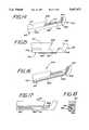
- FIG. 5is a perspective view of an alternative embodiment of the present invention showing a fiberoptic assembly mounted on a hook knife;
- FIG. 6is a cross-sectional view taken along the plane 6--6 in FIG. 5;
- FIG. 7is a cross-sectional view taken along the plane 7--7 in FIG. 5;
- FIG. 8is an enlarged perspective view of an alternative surgical instrument of the present invention in the form of a surgical stitcher, with a fiberoptic assembly mounted to the shaft of the instrument with a bonding agent;
- FIG. 9is an enlarged view of the distal end of the surgical instrument in FIG. 8;
- FIG. 10is a side elevational view of a surgical instrument similar to that of FIG. 1 showing an alternative mounting means;
- FIG. 11is an enlarged cross-sectional view taken along the plane 11--11 of FIG. 10;
- FIG. 12is an enlarged perspective view of a distal operating portion of an alternative embodiment of a surgical instrument of the present invention, showing a portion of a mounting device mounting a fiberoptic assembly to the shaft;
- FIG. 13is a cross-sectional view of the mounting device of FIG. 12 taken along plane 13--13 of FIG. 12;
- FIG. 15is a partial side elevational view of the surgical instrument of FIG. 14 with a partial view of the fiberoptic assembly;
- FIG. 16is a partial perspective view of a distal operating portion of an alternate embodiment of the surgical instrument of FIG. 14 having a groove along a side external surface of the surgical instrument coupled with a hole for receiving a fiberoptic assembly;
- FIG. 17is a partial side elevational view of the surgical instrument in FIG. 16;
- FIG. 18is an enlarged cross-sectional view taken along the plane 18--18 of FIG. 17;
- FIG. 19is a enlarged partial side elevational view of an alternate embodiment of the surgical instrument in FIG. 14, having a protective window, angled hole and a groove on a bottom exterior surface, adapted for receiving the fiberoptic assembly;
- FIGS. 20, 21 and 22are cross-sectional views of alternative embodiments for the mounting means using grooves
- FIG. 23is a partial side elevational view of a further surgical instrument in the form of surgical scissors showing two oppositely positioned fiberoptic assemblies mounted to a distal operating portion of the shaft of the instrument, the fiberoptic assemblies are laterally offset and adhesively bonded to the shaft;
- FIG. 24is an enlarged partial side elevational view of a further surgical instrument in the form of flexible scissors showing a fiberoptic assembly coupled to a distal operating portion of the instrument;
- FIG. 25is a side elevational view of an embodiment of a surgical instrument in the form of a Rongeurs showing two fiberoptic assemblies;
- FIG. 27is a side elevational view with an alternative embodiment in a partial cross-sectional view showing a rod lens used as part of the optical assembly.
- the surgical instrument 10includes an elongated shaft 12 with a handle member 16 mounted on a proximal end 18 of the shaft 12 and a distal operating portion 15 extending at least about one-third of the length of the shaft 12.
- a working element 14such as scissor blades 28 and 30 is disposed on a distal end 19 of the shaft 12 for manipulating tissue during the course of a surgical procedure.
- the handle or handle member 16is the portion of the instrument 10 which is generally held by the surgeon while the distal operating portion 15 is that portion which is generally inserted into or placed such that it can be in contact with the patient.
- some of the shaft 12may extend between the handle and the operating portion. In the case of surgical instrument 10, the operating portion 15 is about one-third the length of the shaft 12.
- the shaft 12preferably includes an actuating mechanism operably coupled to the working element 14 to operate the element.
- the shaft 12can be a rigid tube 40 with its proximal end 18 fitted into a bore formed in a first handle member 20. Pivotally joined to the first handle member 20 at pivot 22 is a second handle member 24.
- An actuating rod or cable 26is appropriately affixed to the upper end 25 of the second handle member 24 and extends through the lumen of the tube 40 to join the movable scissor blade 28 of the working element 14.
- the scissor blade 30is preferably rigidly secured to the distal end 19 of the tube 40.
- the actuating rod or cable 26passes through the tube 40.
- Affixed to the exterior wall of the shaft 12are fiberoptic assemblies 36 and 37.
- the rod or cable 26moves reciprocally within the tube 40 to cause the movable scissor blade 28 to open and close in a scissors-like action relative to the secured scissor blade 30.
- the fiberoptic assemblies 36 and 37each include image fibers 44 having respective proximal ends 48 and 49, and distal ends, with an objective lens 46 mounted on distal end 38 of the image fibers 44 of fiberoptic assembly 36 for defining a predetermined field-of-view which includes at least part of the working element 14.
- the distal end of fiberoptic assembly 37also has mounted an objective lens, but is hidden from the view in FIG. 1.
- the objective lens 46is affixed to the distal end 38 of the fiberoptic assembly 36 to focus the light rays reflected from the illuminated surgical site onto the plane occupied by the distal end 38 of the image fibers 44 contained within the fiberoptic assembly 36.
- Fiber optic assembly 37has the same structure, but is not shown in FIG. 3.
- One or both of the fiberoptic assemblies 36 and 37can include illumination fibers. As shown in FIG. 2, illumination fibers 42 are included as part of the same fiberoptic bundle as the image fibers 44. Alternatively, a single or several illumination fibers can be included separately from the image fibers 44.
- the proximal ends 48 and 49 of the fiberoptic assemblies 36 and 37enter a molded plastic hub member 50 where illumination fibers 42 are separated from the plurality of image fibers and then brought out through a protective sheath 52 to a connector 54 which is adapted to be connected to a light source.
- the plurality of image fibersare brought out through the hub member 50 and through another protective sheath 56 to an appropriate connector 58 which is designed to mate with a viewing system.
- the viewing systemmay, in its simplest form, comprise an eyepiece (not shown), which provides direct viewing of the image focused upon the distal end of the image fibers 44 by the objective lens 46.
- the imagemay also be fed to a video camera whose output is transmitted to a viewing screen for observation by the surgeon and the surgical support staff.
- mounting means 59can include a bonding agent 60, such as epoxy, and is provided for mounting the fiberoptic assembly 36 to the shaft 12 along substantially the entire length of the operating portion 15 of the shaft 12.
- the fiberoptic assembly 36is mounted to the exterior of the operating portion of the shaft 12.
- the distal end 38 of the image fibers 44is positioned at a predetermined portion of the working element 14 to define the field-of-view of the fiberoptic assembly 36.
- the distal operating portion 15can extend along various lengths of the shaft 12, but generally extends about one-third or more of the length of the shaft 12. Preferably, the operating portion 15 extends about one-half or more of the length of the shaft 12, and most preferably along substantially the entire length of the shaft 12, to provide secure attachment, flexibility of application, and minimal invasion into a patient's body cavity, while preserving the tactile feedback of the instrument.
- the mounting means 59in this case the bonding agent 60, is coupled to an exterior surface 64 of the operating portion 15 of the shaft 12.
- the mounting means 59preferably attaches the fiberoptic assemblies 36 and 37 substantially along the entire length of the shaft 12 and a portion of the handle member 16. This provides the best tactile feel for the surgeon because the fiberoptic assemblies 36 and 37 are kept from interfering with the surgeon's hands and the opening in the patient.
- a magnetic coupling techniquecan be utilized, for example, for initially aligning one or more of the fiberoptic assemblies with the shaft prior to attachment or coupling, or applying an adhesive bonding material and the like.
- This magnetic coupling techniquecan be used in any of the surgical instruments of this invention, alone or in combination with one or more of the mounting devices or adhesives.
- Fiberoptic assemblies suitable for use in practicing the present inventioncan be of the super-thin type disclosed in U.S. Pat. No. 4,867,529 to Utsumi et al. In one such fiberscope, the outside diameter can be less than about 0.5 mm.
- the fiberoptic assembly 36may include about 10,000 image fibers 44, each about 5 to 10 micrometers in diameter, which are fused together at each end to thereby preserve their positional relationship relative to one another.
- the viewing systemcan include appropriate circuitry and means for magnification of the image, to allow a surgeon to see objects that are otherwise difficult to see with the naked eye.
- An optical system designed for use in the present inventionwill have a field-of-view defined by a cone whose apex angle, ⁇ (phi), is in the range of from about 50 degrees to about 70 degrees when the object being viewed is in an air environment and a range of about 37 degrees to about 52 degrees if the object is immersed in a saline solution. It will provide a good image of the object placed about 2 mm to about 20 mm from the objective lens 46.
- the magnificationcan then be computed using the formula:
- magnification, Mis a minimum of about 26 times and a maximum of about 38 times.
- the shaft 12 and mounting means 59can be adapted and constructed to have a small outside diameter such that the instrument 10 can be passed through an introducer, a cannula or directly into a narrow lumen or small surgical incision and still have a sufficient length-to allow the working element 14 to reach the organ or tissue to be manipulated or cut.
- the cross-section of the operating portion 15 of the instrument 10consists essentially of the shaft 12, the image fibers 44, and at least one illumination fiber 42 and the mounting means 59. This provides a surgical instrument of minimum size and maximum tactile feel for the surgeon.
- FIG. 4shows an embodiment similar to the FIG. 1 embodiment except that a fiberoptic assembly is coupled or mounted to a working element 62 that is a conventional Rongeurs forceps.
- the tubular shaft 12has cup-shaped jaws or paddles 66 affixed to the distal end 19 thereof and appropriately hinged and connected to an actuating rod or cable 26, similar to that described above.
- the fiberoptic assemblies 36 and 37are again routed along substantially the entire length of the shaft 12 with the objective lens 46 arranged along an optical axis so as to be able to view the particular bone or other tissue to be grasped by the forceps cup-shaped paddles 66 when the scissors-style handle 16 is manipulated.
- FIGS. 5-7illustrate yet another surgical instrument 70 of this invention, in the form of a surgical hook knife, to permit viewing of a nerve, ligament or other tissue to be severed, for example.
- This instrument 70includes an elongated rigid shaft 72 having a generally rectangular cross-section as seen in FIG. 6.
- the shaft 72has a proximal end 74 fitted into a handle member 76 so that it can be conveniently and comfortably grasped by the surgeon.
- the shaft 72is preferably made from stainless steel and its distal end is curved as shown as hook 78, terminating in a point 80 and having a beveled cutting edge or accurate blade 82 extending over the inward-facing arcuate portion of the hook 78.
- the instrument 70is typically used by inserting the shaft 72 of the knife through an opening until the arcuate blade 82 is disposed distally of the tissue to be severed. Cutting takes place by then pulling instrument 70 back in the proximal direction which allows the cutting edge or accurate blade 82 to cut the tissue. Carpal tunnel surgery is often performed using this type of instrument.
- At least one fiberoptic assemblyis affixed to the instrument 70 in such a way that the surgical site can be viewed, either directly or indirectly, in the manner previously described.
- Connectors 79 and 89are adapted to mate with a light source and viewing system, respectively, as previously discussed.
- the fiberoptic assembly 84includes illumination and image fibers that pass through sheaths 81 and 90 and terminate in connectors 79 and 89, respectively.
- the image connector 89is joined to a plurality of image fibers within the sheath 90 which unite in a hub 83 with the illumination fibers in the fiberoptic bundle 84. This bundle passes through a flexible strain relief member 92 attached to the proximal end of the handle member 76 of the hook knife instrument 70.
- the fiberoptic assembly 84extends along an upper side surface 86 of the shaft 72. Upon leaving the shaft 72, the fiberoptic assembly 84 can pass through the handle member 76 or be mounted on a side 88 of the handle member 76 as shown in FIG. 6. Near the distal end of the shaft 72, the fiberoptic assembly 84 wraps about the side surface of the shaft, such that its objective lens 94 becomes optically aligned with the knife cutting edge 82.
- One observing the image exiting the proximal end of the image fibers in the fiberoptic assembly 84obtains a clear view of the surgical site where the blade 82 interacts with the tissue. This greatly generally improves a surgeon's ability to locate and identify the tissue to be manipulated or cut.
- the fiberoptic assembly 84is preferably mounted by epoxy bonding along substantially the length of the exterior surface of the shaft 72. As shown, the fiberoptic assembly 84 can be mounted on one surface such as the upper side surface 86 and wrapped around the shaft 72 to provide a side view. This is advantageous where space is available on one side for the fiberoptic bundle but viewing is desired from another angle. A similar wrap around function is shown in FIGS. 1 and 4.
- FIGS. 8 and 9show another surgical instrument of the present invention in the form of a surgical stitcher, such as an ACCUFEX®brand Meniscal Stitcher sold by Accufex Microsurgical, Inc. used in arthroscopic knee surgery.
- the surgical instrument 95has an elongated rigid tubular shaft 96 having lumens 98 and 100 extending from its proximal end 101 to its distal end 102. Surrounding the proximal end 101 of the shaft 96 is a knurled outwardly extending handle member 104.
- the lumens 98 and 100accommodate stitching needles 106 and 108.
- an optical fiber assembly 110including illumination fibers or bundle 114 and image fibers or bundle 116 as best seen in FIG. 9. Attached to the distal ends of the image fibers 116 is an objective lens 115 positioned to view the distal end portions of the needles 106 and 108 exiting the lumens 98 and 100 in the shaft 96.
- the illumination fibers 114are brought out through a hub member 118 to a connector 120 adapted to mate with a jack of a suitable light source (not shown).
- the image fibers 116pass through the hub member 118 and terminate in a connector 122 adapted to mate with the image input of a suitable viewing device, such as a video camera and associated video display means.
- the rigid tubular shaft 96acts as an introduction cannula and it is passed through a small surgical opening into a knee joint space so that its distal end 102 can be brought up against the meniscus at a desired location.
- a surgeonis able to precisely locate the distal end 102 of the instrument 95 at the desired site.
- the instrument 95is oriented so that the needles 106 and 108, having been inserted in the entire length of the shaft 96, will pierce both sides of the tear in the meniscus to be repaired, and will continue on through the capsule and soft tissues until the needles 106 and 108 perforate and exit the skin opposite the small surgical entry.
- the needles 106 and 108with a long strand of suture material passing through their eyes, are then pulled out of the tissue, and a loop of suture material is drawn taut so as to complete the internal half of the stitch. A knot is then tied and drawn tight against the outer surface of the capsule through a small incision bridging the exit perforations of the needles 106 and 108. This procedure may be repeated as many times as necessary to effect repair of the tear.
- Irrigation fluidwhich distends the joint and sweeps away blood clouded fluid, may be injected through and removed from the irrigation portals. While irrigation portals are generally of a small diameter, operating portals must necessarily be large enough to pass surgical tools and arthroscopes. It is, of course, desired to limit the number and size of operating portals required for surgery.
- the viewing optics of the present inventioncan be adhered or appropriately mounted to a portion of an exterior surface of the meniscus cutter, thus obviating the need for a relatively large operating portal which would otherwise be used to accommodate that arthroscope.
- FIG. 10shows an alternative embodiment 210 similar to FIG. 1.
- the mounting meansis a mounting device 264, substantially complementarily configured to receive at least a portion of a shaft 212, for a minimal invasive diameter and secure attachment.
- the handle member 216, actuating means 226 and connectors 254 and 258are as described before.
- the mounting device 264include's a circular cross-section and is substantially tubular in shape. It should be noted that various shapes, geometries and cross-sections can be used in this invention.
- the mounting device 264can be made of a molded or shrinkable tubing 265.
- the mounting device 264is in the form of a tube with a thin wall retaining the fiberoptic assembly 236 between the wall of the tube and the shaft 212 having at least one conduit for receiving the image fibers 244. This provides a tight and conforming fit.
- the fiberoptic assembly 236can first be attached to the shaft 212 magnetically or by use of an adhesive.
- the mounting device 264such as a shrinkable tubing 265, is then placed over the combination of the fiberoptic assembly 236 and shaft 212 to retain the fiberoptic assembly 236 in place.
- shrinkable tubing 265is particularly useful. Instead of placing the fiberoptic assembly 236 between the shrinkable tubing 265 and shaft 212, it can be placed within the wall of the shrinkable tubing 265.
- the molded or shrinkable tubing 265alternatively can include three conduits for receiving the image fibers 244, and first and second illumination fibers 242 and 243.
- the illumination fibers 242 and 243are mounted to an operating portion 215 of the shaft 212 with the distal end of the illumination fibers 242 and 243 positioned to project light in the field-of-view which includes the working element 214.
- the cross-section area of the mounting device 264, the image fibers 244 and illumination fibers 242 and 243 combinedis less than about one-third of the cross-section area of the total cross-section area defined by the operating portion 215 of the shaft 212, the mounting device 264, the image fibers 244 and illumination fibers 242 and 243.
- a bonding agent 261can also be used to couple an exterior surface of the shaft 212 to an interior surface of the tubing 265.
- a further bonding agent 262can also be utilized to couple the fiberoptic assembly 236 to the shaft 212 where it extends beyond the mounting device 264. As before, a portion of the fiberoptic assembly 236 can also be mounted on the handle member 216. In FIG. 10, the fiberoptic assembly 236 is shown flush with the distal end 266 of the mounting device 264, thus further bonding is not necessary near the working element 214.
- the operating portion 215 of the shaft 212that portion which can be expected to be inserted into the patient, extends over half of the length of the shaft 212. This portion of the shaft 212 is therefore covered by the mounting device 264.
- the mounting meansincludes the tubing 265 and bonding agent 262 to give particularly effective mounting.
- the bonding agent 262is not necessary and the tubing 265 can function as the mounting means, and if desired, can extend further along the shaft 212.
- Suitable materials for the mounting device 264include heat-shrink teflon, polyolefin and other heat-shrink plastics shown in the art.
- FIGS. 12 and 13a clip mounting device 364 for use with a surgical instrument 310 of this invention, is shown in FIGS. 12 and 13.
- the surgical instrument 310 of FIGS. 12 and 13is similar in structure to that of FIGS. 10 and 11 with the mounting means being the mounting device 364.
- FIG. 12is a cut-away view and the mounting device 364 extends a length along the shaft 312 similar to that shown for the mounting device 264 in FIG. 10.
- the mounting device 364comprises a substantially arcuate body 365 having a thin wall 367 defining an upper section 368 and a lower section 369, inner and outer surfaces 370 and 371, a distal aperture at a distal end 366, a proximal aperture at a proximal end (not shown) and an axial channel between the ends.
- the arcuate body 365has an elongated opening or channel deferred between the ends 373 and 375 defining a snap-fittable channel 377 for receiving a portion of the shaft 312.
- the mounting device 364is of a sufficient length and diameter to provide a secure connection to the shaft 312.
- a portion of the fiberoptic assemblyis received within the thin wall 367 of the arcuate body 365 to place at least a portion of the working element 314 within the field-of-view.
- the mounting device 364is coupled to the distal operating portion of the shaft 312. It should be noted that the mounting device 364 can also be utilized to securely couple other portions of the fiberoptic assembly to other locations along the shaft 312 as well.
- the fiberoptic assemblyis carried within the upper section 368. More particularly, conduits receive image fibers 344, and first and second illumination fibers 342 and 343, respectively.
- the mounting device 364can be slidably adjusted along the shaft 312.
- the inner surface 370 of the mounting device 364can be adhesively bonded with a bonding agent to an instrument for minimizing unwanted movement or slippage.
- the resiliency of its arcuate body 365will retain the mounting device 364 on the shaft 312.
- Suitable materials for the arcuate body 365include polypropylene, teflon, and other plastics known in the art.
- Exterior mounting of the fiberoptics by use of the mounting devices and methods of this inventionprovide for simplified manufacture and repair of instruments, facilitate attachment and removal of the components, and do not require complicated tooling such as drilling or milling to manufacture.
- FIGS. 14 and 15show an alternate surgical instrument of the present invention.
- the surgical instrument 410includes an elongated shaft 412 having a proximal portion mounted on a handle (not shown) and a distal operating portion 415 defining an opening 478.
- a working element in the form of a stationary element 430 and moving element 428is disposed on the distal operating portion 415 of the shaft 412.
- the opening 478is proximate to the working element, in this case moving element 428.
- An elongated, flexible fiberoptic assembly 436is mounted on the shaft 412.
- the assembly 436includes illumination and image fibers in a common sheath with an objective lens 426 affixed to the distal end of the image fibers, for defining a predetermined field-of-view.
- the fiberoptic assembly 436is mounted on the shaft 412 with a portion extending at least partially through the opening 478, such that at least a portion of the working element is within the field-of-view when in use.
- the opening 478is preferably a hole which extends through the shaft 412 with the fiberoptic assembly 436 extending at least partially through the hole.
- First and second elements 411 and 413 comprising the shaft 412are complementarily configured and include an elongated groove 417 and flange 421 for allowing lateral movement and interconnection.
- the fiberoptic assembly 436is appropriately coupled or adhesively bonded to the shaft 412 at least adjacent to the distal operating portion 415 or along the entire length of the shaft 412. As shown, the fiberoptic assembly 436 is mounted on the exterior of the shaft 412 along its length toward the handle (not shown). Alternatively, the bottom of the shaft 412 can define a groove into which the fiberoptic assembly 436 is received.
- the fiberoptic assembly 436is also preferably bonded within the opening 478.
- FIGS. 16-18An alternative embodiment for a Rongeurs forceps 510 is shown in FIGS. 16-18.
- the mounting meansincludes an arcuate and inclined opening or groove 585 that extends from adjacent the working element 514 along the side portion 513 of the shaft 512.
- a side groove 586 on the exterior surface of side portion 513 of the shaft 512is associated with the arcuate groove 585 and extends from the arcuate groove 585 in a direction toward the proximal handle member (not shown).
- the side groove 586extends along the axis of the shaft 512 and is adapted to receive at least a portion of the length of the fiberoptic assembly 536.
- the arcuate groove 585is constructed to give an advantageous view and perspective of the working element 514.
- an adhesivecan be utilized to bond the fiberoptic assembly 536 to the grooves 585 and 586 for an improved and secure coupling. It should be noted, however, that an adhesive is not necessary in this embodiment.
- the resiliency of the fiberoptic assembly 536can be used to retain itself in the grooves 585 and 586. In the case where an adhesive is used, the adhesive need not be permanent to allow the components to be disconnected, removed, cleaned and the like.
- FIG. 19An alternative embodiment for a mounting means on a Rongeurs forceps 610 is shown in FIG. 19.
- the shaft 612defines an opening, in this case a hole 678 which extends through shaft 612.
- a groove 617defined by the bottom portion of the shaft 612 to receive and hold the fiberoptic assembly 636.
- Shaft 612defines a substantially circular recess 641 for receiving a protective window 645, for minimizing damage to the objective lens 646 of the fiberoptic assembly 636.
- the protective window 645is preferably positioned adjacent the objective lens 646 and is flush with the exterior surface of the shaft 612.
- the protective window 645can be any transparent or clear material that can withstand the environment to which it will be exposed to.
- the materials for the window 645can include glass, epoxy, sapphire, various plastics and the like.
- FIGS. 20, 21 and 22show various embodiments for mounting means using grooves such as shown in FIGS. 16-19. These designs can be used with adhesives or bonding agents, but are generally not used with such so that the fiberoptic assemblies are releasably retained in the grooves.
- the side groove 586is circular and complementarily configured to receive the fiberoptic assembly 536 securely on the shaft 512.
- the circular groove 586 as shown in FIG. 20can have a slightly larger diameter than the outer diameter of the fiberoptic assembly 536 for a tight and secure fit, without compressing the fiberoptic assembly 536.
- the top opening 555 of the side groove 586 defined by the shaft 512is smaller across than the maximum diameter of the side groove 586 and the diameter of the fiberoptic assembly 536. This allows the resiliency of the fiberoptic assembly 536 to provide a snap fit.
- a groove 679which is substantially trapezoidal in shape, having a planar bottom 651 and sidewalls 653.
- the sidewalls 653are angled inwardly travelling radially away from the bottom 651 toward the top opening 655 to compress and securely hold the fiberoptic assembly 636 in the shaft 612.
- the fiberoptic assembly 636can be provided with an elongated resilient case 639 into which the image fibers 644 and illumination fibers 642 (in this case 3) are received.
- the casewhich can be made of a plastic or rubber tubing known in the art allows the fiberoptic assembly 636 to be snapped in and out of the groove 679.
- the case 639can be made of metal such as stainless steel and be pre-bent to fit into the groove 617 and hole 678 (FIG. 19) or in the case of a device as in FIGS. 16-18, into the side arcuate groove 585 to provide the desired view.
- FIG. 22Still another alternative mounting means is shown in FIG. 22.
- a cross-sectional view of a portion of a surgical instrumentis shown, having a semi-circular side groove 586 defined by the shaft 512.
- the fiberoptic assembly 536includes an elongated retaining member 561 in the form of an elastic member, substantially along the length of the fiberoptic assembly 536, adapted to be received in the groove 586.
- the retaining mounting member 561is complementarily configured to be tightly received in groove 586, to allow the fiberoptic assembly 536 to be removably coupled to the shaft 512.
- the fiberoptic assembly 536 in FIG. 22includes image fibers 544 with illumination fibers, or optionally, two illumination fibers 542.
- the retaining member 561can be made of a resilient material such as plastic, rubber, or flexible magnetic material for various applications, so long as the material can withstand the environment to which it will be exposed to and will interconnect and mate with the groove 586.
- the fiberoptic assemblycan be releasably received in the grooves, and easily removed, for example, for sterilization of the surgical instrument and replacement of the fiberoptic assembly.
- the surgical instrument 710is in the form of a scissors and includes an elongated shaft 712 having a proximal handle as described before and a distal operating portion 715.
- a working element 714 in the form of scissorsis disposed on a distal end of the shaft 712 for manipulating or cutting tissue.
- two elongated fiberoptic assemblies 736 and 737each having distal ends 738 and 739 with lenses 740 and 741 mounted on respective distal ends 230 and 232 for defining different predetermined first and second field-of-views respectively.
- This construction with at least two fiberoptic assemblies 736 and 737can provide two different perspectives of the working element 714, improved depth perception, reduced shadowing and alternate views of the surgical site.
- the distal ends 738 and 739 of the fiberoptic assemblies 736 and 737are laterally offset to provide a close-up and wide field-of-views, respectively.
- the distal ends 738 and 739, and the lenses 740 and 741can have different focal lengths for providing a close-up and wide field-of-view, for example.
- a surgeoncan utilize a switching system to switch back and forth as desired for close-up or wide views, when observing the field-of-views, for example.
- the two viewscan be observed simultaneously on a single monitor, or switching means can be used to allow simultaneous or alternative observation of the field-of-views, for example.
- FIG. 24a further alternate embodiment of the surgical instrument is shown, in the form of flexible forceps.
- This surgical instrument 810includes mounting means preferably on those portions of the instrument 810 which do not flex.
- mounting devices 863 and 864can be molded or shrunk to respective portions of the shaft 812 to retain the fiberoptic assembly 836.
- the mounting devices 863 and 864can include the features described with respect to the mounting devices in the previous figures. Alternatively, a bonding agent can be used as described above.
- the mounting devices 863 and 864, and fiberoptic assembly 836can be flexible to allow the fiberoptic assembly 836 to be adjusted with the instrument 810, without interrupting or misaligning the field-of-view.
- FIGS. 25 and 26An alternate embodiment of the present invention is shown in FIGS. 25 and 26.
- the structure in this embodimentis similar to many of the embodiments previously discussed.
- the surgical instrument 910includes elongated fiberoptic assemblies 936 and 937 having distal ends 938 and 939 defining a first and a second predetermined field-of-views.
- the distal ends 938 and 939have objective lenses 940 and 941 having substantially similar focal lengths.
- the distal ends 938 and 939are slightly angled toward each other, as shown in FIG. 26, for example, providing a stereoscopic image.
- the viewing system 911provides a stereoscopic image defined by the first and second fields-of-view for real time or concurrent viewing of the surgical site. If two eyepieces are used in a binocular-like fashion, for example, each field-of-view can be fed separately and concurrently to each eyepiece. Alternatively, each field-of-view can be fed to one or more separate monitoring devices for viewing the surgical site.
- the viewing system 911includes a device for providing a three-dimensional image defined by the fields-of-view.
- the present inventionincludes a method of retrofitting an existing surgical instrument to carry fiberoptics. This can be done with the examples of FIGS. 1-7 by using a bonding agent as described above.
- a reference gaugecan be used. The reference gauge includes at least two steps, one for the end of the instrument and one for the distal end of the fiberoptic bundle to locate the lens while the fiberoptic bundle is being mounted to the shaft.
- the opening 478is drilled in the distal operating portion 415 adjacent the stationary element 430.
- the fiberoptic assembly 436is then inserted into the opening 478 and an appropriate bonding agent is used to fasten it to the shaft 412.
- a portion of the shaft 512is milled to provide the grooves 585 and 586 which extend on the outer surface of the shaft 512. Thereafter, the fiberoptic assembly 536 is mounted in the grooves 585 and 586 as discussed above.
- the hole 678is drilled in an existing surgical instrument adjacent a working element 614.
- the shaft 612is then appropriately milled to create a groove like that shown in FIGS. 20-22 to receive the fiberoptic assembly 636.
- a still further alternate surgical instrument 1010 of this inventionis shown in the form of a scissors.
- the surgical instrument 1010is adapted for use with a viewing system 1011.
- the surgical instrument 1010includes an elongated shaft 1012 including a working element 1014 on a distal operating portion 1015, and a handle 1016.
- the optical assembly 1036uses an image fiber in the form of a rod lens 1046.
- the rod lens 1046is mounted on at least an exterior portion of the shaft 1012. Also provided is an intermediate device 1013 between the rod lens 1046 and viewing system 1011 for transferring an image from the rod lens 1046 to the viewing system 1011.
- the intermediate device 1013includes a charge coupled device (CCD) chip 1050 and a camera 1051, coupled between the rod lens 1046 and the viewing system 1011.
- the CCD chip 1050is substantially adjacent to and preferably enclosed in the handle 1016.
- the intermediate device 1013can further include focusing lens system 1052 in the form of a focusing ring, for example, for focusing the image from the rod lens 1046.
- the proximal portion of the rod lens 1046, the focusing lens system 1052 and the CCD chip 1050are substantially enclosed and aligned in the handle 1016.
- the intermediate device 1013can include a flexible fiberoptic viewing bundle as detailed with respect to the surgical instruments of this invention.
- the fiberoptic bundlewould be operatively associated with the proximal end of the rod lens 1046 and the viewing system.
Landscapes
- Health & Medical Sciences (AREA)
- Life Sciences & Earth Sciences (AREA)
- Surgery (AREA)
- Biomedical Technology (AREA)
- Public Health (AREA)
- Optics & Photonics (AREA)
- Veterinary Medicine (AREA)
- Nuclear Medicine, Radiotherapy & Molecular Imaging (AREA)
- General Health & Medical Sciences (AREA)
- Engineering & Computer Science (AREA)
- Physics & Mathematics (AREA)
- Heart & Thoracic Surgery (AREA)
- Medical Informatics (AREA)
- Molecular Biology (AREA)
- Animal Behavior & Ethology (AREA)
- Biophysics (AREA)
- Radiology & Medical Imaging (AREA)
- Pathology (AREA)
- Ophthalmology & Optometry (AREA)
- Surgical Instruments (AREA)
- Endoscopes (AREA)
Abstract
Description
M=((D/2)/(L tan Φ/2))
Claims (29)
Priority Applications (4)
| Application Number | Priority Date | Filing Date | Title |
|---|---|---|---|
| US08/472,187US5667473A (en) | 1994-03-18 | 1995-06-07 | Surgical instrument and method for use with a viewing system |
| US08/596,073US5857961A (en) | 1995-06-07 | 1996-02-06 | Surgical instrument for use with a viewing system |
| PCT/US1996/009269WO1996039915A1 (en) | 1995-06-07 | 1996-06-06 | Surgical instrument for use with a viewing system |
| EP96918245AEP0836405A4 (en) | 1995-06-07 | 1996-06-06 | Surgical instrument for use with a viewing system |
Applications Claiming Priority (2)
| Application Number | Priority Date | Filing Date | Title |
|---|---|---|---|
| US08/210,588US5667472A (en) | 1994-03-18 | 1994-03-18 | Surgical instrument and method for use with a viewing system |
| US08/472,187US5667473A (en) | 1994-03-18 | 1995-06-07 | Surgical instrument and method for use with a viewing system |
Related Parent Applications (1)
| Application Number | Title | Priority Date | Filing Date |
|---|---|---|---|
| US08/210,588DivisionUS5667472A (en) | 1994-03-18 | 1994-03-18 | Surgical instrument and method for use with a viewing system |
Related Child Applications (1)
| Application Number | Title | Priority Date | Filing Date |
|---|---|---|---|
| US08/596,073Continuation-In-PartUS5857961A (en) | 1995-06-07 | 1996-02-06 | Surgical instrument for use with a viewing system |
Publications (1)
| Publication Number | Publication Date |
|---|---|
| US5667473Atrue US5667473A (en) | 1997-09-16 |
Family
ID=22783484
Family Applications (2)
| Application Number | Title | Priority Date | Filing Date |
|---|---|---|---|
| US08/210,588Expired - LifetimeUS5667472A (en) | 1994-03-18 | 1994-03-18 | Surgical instrument and method for use with a viewing system |
| US08/472,187Expired - LifetimeUS5667473A (en) | 1994-03-18 | 1995-06-07 | Surgical instrument and method for use with a viewing system |
Family Applications Before (1)
| Application Number | Title | Priority Date | Filing Date |
|---|---|---|---|
| US08/210,588Expired - LifetimeUS5667472A (en) | 1994-03-18 | 1994-03-18 | Surgical instrument and method for use with a viewing system |
Country Status (1)
| Country | Link |
|---|---|
| US (2) | US5667472A (en) |
Cited By (103)
| Publication number | Priority date | Publication date | Assignee | Title |
|---|---|---|---|---|
| US5857961A (en)* | 1995-06-07 | 1999-01-12 | Clarus Medical Systems, Inc. | Surgical instrument for use with a viewing system |
| US5916149A (en)* | 1995-10-25 | 1999-06-29 | Ryan, Jr.; Edwin H. | Shielded illumination device for ophthalmic surgery and the like |
| US5928137A (en)* | 1996-05-03 | 1999-07-27 | Green; Philip S. | System and method for endoscopic imaging and endosurgery |
| US5944657A (en)* | 1998-02-02 | 1999-08-31 | Djurovic; Zarija | Retractor apparatus |
| US5954635A (en)* | 1996-03-22 | 1999-09-21 | Sdgi Holdings Inc. | Devices and methods for percutaneous surgery |
| US6006001A (en)* | 1996-12-02 | 1999-12-21 | The Research Foundation Of Cuny | Fiberoptic assembly useful in optical spectroscopy |
| US6066102A (en)* | 1998-03-09 | 2000-05-23 | Spectrascience, Inc. | Optical biopsy forceps system and method of diagnosing tissue |
| US6129683A (en)* | 1996-05-07 | 2000-10-10 | Spectrascience, Inc. | Optical biopsy forceps |
| US6152871A (en)* | 1996-03-22 | 2000-11-28 | Sdgi Holdings, Inc. | Apparatus for percutaneous surgery |
| US6162170A (en)* | 1996-03-22 | 2000-12-19 | Sdgi Holdings, Inc. | Devices and methods for percutaneous surgery |
| US6162209A (en)* | 1998-11-17 | 2000-12-19 | Scimed Life Systems, Inc. | Multi-function surgical instrument tool actuator assembly |
| US6213940B1 (en) | 1996-04-26 | 2001-04-10 | United States Surgical Corporation | Surgical retractor including coil spring suture mount |
| US6221007B1 (en) | 1996-05-03 | 2001-04-24 | Philip S. Green | System and method for endoscopic imaging and endosurgery |
| WO2002085194A1 (en)* | 2001-04-20 | 2002-10-31 | Power Medical Interventions, Inc. | Imaging device |
| US20020173786A1 (en)* | 2001-05-21 | 2002-11-21 | Kortenbach Juergen A. | Methods and apparatus for on-endoscope instruments having end effectors and combinations of on-endoscope and through-endoscope instruments |
| US6517545B1 (en) | 2000-10-24 | 2003-02-11 | John B. Mazur | Surgical cutting instrument having concave jaw tips |
| US6565508B2 (en) | 1998-01-23 | 2003-05-20 | United States Surgical Corporation | Surgical instrument |
| US6648902B2 (en) | 2000-07-20 | 2003-11-18 | Gmp Surgical Solutions, Inc. | Fiberoptic lighting accessory |
| US20030233092A1 (en)* | 2000-12-06 | 2003-12-18 | Kortenbach Juergen A. | Methods and apparatus for the treatment of gastric ulcers |
| US6679833B2 (en) | 1996-03-22 | 2004-01-20 | Sdgi Holdings, Inc. | Devices and methods for percutaneous surgery |
| US6685716B1 (en)* | 2000-01-04 | 2004-02-03 | Transvascular, Inc. | Over-the-wire apparatus and method for open surgery making of fluid connection between two neighboring vessels |
| US20040032751A1 (en)* | 2001-07-20 | 2004-02-19 | Solovay Kenneth S. | Light coupling assembly |
| US6702820B2 (en) | 2000-10-24 | 2004-03-09 | John B. Mazur | Surgical cutting instrument having concative jaw tips |
| EP1067875A4 (en)* | 1998-04-01 | 2004-08-04 | Promex Inc | Non-reflective surfaces for surgical procedures |
| US20040186346A1 (en)* | 1996-03-22 | 2004-09-23 | Smith Maurice M. | Devices and methods for percutaneous surgery |
| US20040267253A1 (en)* | 2003-06-30 | 2004-12-30 | Klotz Conrad Lee | Imaging and surgical procedure for carpal tunnel syndrome |
| US20040267243A1 (en)* | 2003-06-30 | 2004-12-30 | Klotz Conrad Lee | Surgical scalpel and system particularly for use in a transverse carpal ligament surgical procedure |
| US20050038423A1 (en)* | 2003-06-30 | 2005-02-17 | Makin Inder Raj S. | Imaging and therapeutic procedure for carpal tunnel syndrome |
| US20050238289A1 (en)* | 2003-11-25 | 2005-10-27 | Zygo Corporation | Optical fiber connectors and systems including optical fiber connectors |
| US7056321B2 (en) | 2000-08-01 | 2006-06-06 | Endius, Incorporated | Method of securing vertebrae |
| US20060155168A1 (en)* | 2005-01-10 | 2006-07-13 | Pease Alfred A | Optical snake |
| US20060167340A1 (en)* | 2005-01-10 | 2006-07-27 | Pease Alfred A | Optical snake |
| US20060241350A1 (en)* | 2005-04-22 | 2006-10-26 | Sdgi Holdings, Inc. | Instruments and methods for selective tissue retraction through a retractor sleeve |
| US7137949B2 (en) | 2001-07-13 | 2006-11-21 | United States Surgical Corporation | Surgical instrument |
| US20060281972A1 (en)* | 2005-01-10 | 2006-12-14 | Pease Alfred A | Remote inspection device |
| US20070021655A1 (en)* | 2005-07-15 | 2007-01-25 | Dr. Ayoub Sayeg | Method and instruments for breast augmentation mammaplasty |
| US20070034750A1 (en)* | 2005-08-10 | 2007-02-15 | Kns Associates, Inc. | Tubing mounting clip |
| US20070117437A1 (en)* | 2005-01-10 | 2007-05-24 | Perceptron, Inc. | Detachable coupling for a remote inspection device |
| US20070185379A1 (en)* | 2005-01-10 | 2007-08-09 | Perceptron, Inc. | Modular remote inspection device with digital imager |
| US20070232859A1 (en)* | 2006-02-24 | 2007-10-04 | U.S. Endoscopy Group, Inc. | Endoscopic suction device |
| US20070250100A1 (en)* | 2006-01-09 | 2007-10-25 | Medical Components, Inc. | Pivoting dilator |
| US20070249932A1 (en)* | 2006-04-25 | 2007-10-25 | Shahinian Hrayr K | Remote manipulator with eyeballs |
| US7294104B2 (en) | 1998-01-23 | 2007-11-13 | United States Surgical Corporation | Surgical instrument holder |
| US20070299468A1 (en)* | 2006-06-22 | 2007-12-27 | Viola Frank J | Tissue vitality comparator with light pipe with fiber optic imaging bundle |
| US20070299437A1 (en)* | 2006-06-23 | 2007-12-27 | Podmore Jonathan L | Device for ablation and visualization |
| US20080045859A1 (en)* | 2006-08-19 | 2008-02-21 | Fritsch Michael H | Devices and Methods for In-Vivo Pathology Diagnosis |
| US20080188873A1 (en)* | 2005-01-21 | 2008-08-07 | Giovanni Speziali | Thorascopic Heart Valve Repair Method and Apparatus |
| US20080248673A1 (en)* | 2006-06-30 | 2008-10-09 | Al Boehnlein | Detachable coupling for a remote inspection device |
| US20080269562A1 (en)* | 2007-04-25 | 2008-10-30 | Karl Storz Endovision, Inc. | Endoscope system with pivotable arms |
| DE102008018932A1 (en) | 2007-04-17 | 2008-11-20 | C2Cure Inc., Wilmington | Imaging systems and methods, in particular for use with an instrument used in open surgery |
| US20090023992A1 (en)* | 2007-07-18 | 2009-01-22 | Zvika Gilad | Device and method for viewing a body lumen |
| US20090149716A1 (en)* | 2007-12-07 | 2009-06-11 | Socorro Medical, Inc. | Endoscopic system for accessing constrained surgical spaces |
| US20090318758A1 (en)* | 2004-09-24 | 2009-12-24 | Vivid Medical, Inc. | Pluggable vision module and portable display for endoscopy |
| US7695485B2 (en) | 2001-11-30 | 2010-04-13 | Power Medical Interventions, Llc | Surgical device |
| US20100133320A1 (en)* | 2004-09-10 | 2010-06-03 | Federico Bilotti | Surgical Stapling Instrument |
| US7743960B2 (en) | 2002-06-14 | 2010-06-29 | Power Medical Interventions, Llc | Surgical device |
| US7751870B2 (en) | 2002-01-30 | 2010-07-06 | Power Medical Interventions, Llc | Surgical imaging device |
| US20100198009A1 (en)* | 2004-09-24 | 2010-08-05 | Vivid Medical, Inc. | Disposable endoscope and portable display |
| US20100206099A1 (en)* | 2008-12-03 | 2010-08-19 | Edward Diao | Reusable handpiece for disposable probes |
| US20100208054A1 (en)* | 2004-09-24 | 2010-08-19 | Vivid Medical, Inc. | Disposable microscope and portable display |
| US20110028790A1 (en)* | 2004-09-24 | 2011-02-03 | Vivid Medical, Inc. | Disposable endoscopic access device and portable display |
| US7918230B2 (en) | 2007-09-21 | 2011-04-05 | Tyco Healthcare Group Lp | Surgical device having a rotatable jaw portion |
| US7963433B2 (en) | 2007-09-21 | 2011-06-21 | Tyco Healthcare Group Lp | Surgical device having multiple drivers |
| US7985247B2 (en) | 2000-08-01 | 2011-07-26 | Zimmer Spine, Inc. | Methods and apparatuses for treating the spine through an access device |
| US8016855B2 (en) | 2002-01-08 | 2011-09-13 | Tyco Healthcare Group Lp | Surgical device |
| US20110224485A1 (en)* | 2010-03-12 | 2011-09-15 | Microline Surgical, Inc. | Picture in picture clip applier video system |
| US8025199B2 (en) | 2004-02-23 | 2011-09-27 | Tyco Healthcare Group Lp | Surgical cutting and stapling device |
| US20110257478A1 (en)* | 2010-04-20 | 2011-10-20 | Spinewindow Llc | Method and apparatus for performing retro peritoneal dissection |
| US20120133742A1 (en)* | 2009-07-24 | 2012-05-31 | Degudent Gmbh | Generating a total data set |
| US8229549B2 (en) | 2004-07-09 | 2012-07-24 | Tyco Healthcare Group Lp | Surgical imaging device |
| WO2012158971A3 (en)* | 2011-05-17 | 2013-01-03 | Ammirati Mario | Method and apparatus for delivering an endoscope via microsurgical instruments while performing microscopic |
| US8540746B2 (en) | 1998-08-20 | 2013-09-24 | Zimmer Spine, Inc. | Cannula for receiving surgical instruments |
| US20140025047A1 (en)* | 2007-11-29 | 2014-01-23 | Surgiquest, Inc. | Surgical instruments with improved dexterity for use in minimally invasive surgical procedures |
| US20140081252A1 (en)* | 2012-09-14 | 2014-03-20 | The Spectranetics Corporation | Tissue slitting methods and systems |
| US8696552B2 (en) | 2002-09-30 | 2014-04-15 | Covidien Lp | Self-contained sterilizable surgical system |
| US9044221B2 (en) | 2010-12-29 | 2015-06-02 | Neochord, Inc. | Exchangeable system for minimally invasive beating heart repair of heart valve leaflets |
| US9049351B2 (en) | 2010-05-03 | 2015-06-02 | Inspectron, Inc. | Insulator design for video inspection devices |
| US9113878B2 (en) | 2002-01-08 | 2015-08-25 | Covidien Lp | Pinion clip for right angle linear cutter |
| US9167959B1 (en)* | 2010-03-26 | 2015-10-27 | Optech Ventures, Llc | Illumination for enhanced contrast in debridement apparatus and method |
| US9192374B2 (en) | 2007-10-18 | 2015-11-24 | Neochord, Inc. | Minimally invasive repair of a valve leaflet in a beating heart |
| US20160007843A1 (en)* | 2013-09-27 | 2016-01-14 | Olympus Corporation | Endoscope and endoscope system |
| US20160015460A1 (en)* | 2013-03-26 | 2016-01-21 | Hyung PARK II | Locally invasive surgical apparatus with manipulator for bone fracture treatment |
| US20160038017A1 (en)* | 2013-03-15 | 2016-02-11 | James C. Robinson | Retractor vision system |
| US9295375B2 (en) | 2012-09-27 | 2016-03-29 | Hrayr Karnig Shahinian | Programmable spectral source and design tool for 3D imaging using complementary bandpass filters |
| US9456735B2 (en) | 2012-09-27 | 2016-10-04 | Shahinian Karnig Hrayr | Multi-angle rear-viewing endoscope and method of operation thereof |
| US9549667B2 (en) | 2007-12-18 | 2017-01-24 | Harish M. MANOHARA | Endoscope and system and method of operation thereof |
| US9717403B2 (en) | 2008-12-05 | 2017-08-01 | Jeffrey B. Kleiner | Method and apparatus for performing retro peritoneal dissection |
| US9861261B2 (en) | 2014-03-14 | 2018-01-09 | Hrayr Karnig Shahinian | Endoscope system and method of operation thereof |
| US10588620B2 (en) | 2018-03-23 | 2020-03-17 | Neochord, Inc. | Device for suture attachment for minimally invasive heart valve repair |
| US10695178B2 (en) | 2011-06-01 | 2020-06-30 | Neochord, Inc. | Minimally invasive repair of heart valve leaflets |
| US10765517B2 (en) | 2015-10-01 | 2020-09-08 | Neochord, Inc. | Ringless web for repair of heart valves |
| WO2020198465A1 (en)* | 2019-03-27 | 2020-10-01 | Blue Ocean Bbb, Llc | Carpal tunnel release surgical tool with wireless video capability |
| US10835279B2 (en) | 2013-03-14 | 2020-11-17 | Spectranetics Llc | Distal end supported tissue slitting apparatus |
| US10966709B2 (en) | 2018-09-07 | 2021-04-06 | Neochord, Inc. | Device for suture attachment for minimally invasive heart valve repair |
| US11147713B2 (en)* | 2017-07-17 | 2021-10-19 | 3Nt Medical Ltd. | Ear visualization system |
| US11173030B2 (en) | 2018-05-09 | 2021-11-16 | Neochord, Inc. | Suture length adjustment for minimally invasive heart valve repair |
| US11202557B2 (en) | 2018-12-18 | 2021-12-21 | 3Nt Medical Ltd. | Ear visualization and treatment system |
| US11253360B2 (en) | 2018-05-09 | 2022-02-22 | Neochord, Inc. | Low profile tissue anchor for minimally invasive heart valve repair |
| US11376126B2 (en) | 2019-04-16 | 2022-07-05 | Neochord, Inc. | Transverse helical cardiac anchor for minimally invasive heart valve repair |
| US11529042B2 (en) | 2009-11-13 | 2022-12-20 | Hrayr Karnig Shahinian | Stereo imaging miniature endoscope with single imaging and conjugated multi-bandpass filters |
| US11589989B2 (en) | 2017-03-31 | 2023-02-28 | Neochord, Inc. | Minimally invasive heart valve repair in a beating heart |
| US11986159B2 (en) | 2021-01-11 | 2024-05-21 | 3Nt Medical Ltd. | Ear visualization and treatment system |
| US12208007B2 (en) | 2020-01-16 | 2025-01-28 | Neochord, Inc. | Helical cardiac anchors for minimally invasive heart valve repair |
Families Citing this family (66)
| Publication number | Priority date | Publication date | Assignee | Title |
|---|---|---|---|---|
| US5626607A (en)* | 1995-04-03 | 1997-05-06 | Heartport, Inc. | Clamp assembly and method of use |
| US5944654A (en)* | 1996-11-14 | 1999-08-31 | Vista Medical Technologies, Inc. | Endoscope with replaceable irrigation tube |
| US6086528A (en)* | 1997-09-11 | 2000-07-11 | Adair; Edwin L. | Surgical devices with removable imaging capability and methods of employing same |
| US20010003580A1 (en) | 1998-01-14 | 2001-06-14 | Poh K. Hui | Preparation of a lipid blend and a phospholipid suspension containing the lipid blend |
| US7597698B2 (en)* | 1999-08-10 | 2009-10-06 | Maquet Cardiovascular Llc | Apparatus and method for endoscopic encirclement of pulmonary veins for epicardial ablation |
| US7398781B1 (en) | 1999-08-10 | 2008-07-15 | Maquet Cardiovascular, Llc | Method for subxiphoid endoscopic access |
| US7526342B2 (en) | 1999-08-10 | 2009-04-28 | Maquet Cardiovascular Llc | Apparatus for endoscopic cardiac mapping and lead placement |
| EP1731087A3 (en) | 2000-07-14 | 2008-08-06 | Novadaq Technologies Inc. | Compact fluorescent endoscopy video system |
| US6623489B2 (en)* | 2001-07-11 | 2003-09-23 | Daniel Cherfas | Device for destroying formations in a body |
| US6730076B2 (en) | 2001-09-25 | 2004-05-04 | Alcon, Inc. | Fiberoptic probe tip |
| US20060241496A1 (en) | 2002-01-15 | 2006-10-26 | Xillix Technologies Corp. | Filter for use with imaging endoscopes |
| DE10349825B3 (en)* | 2003-10-24 | 2005-07-14 | Karl Storz Gmbh & Co. Kg | Medical instrument |
| DE102004005709A1 (en)* | 2004-02-05 | 2005-08-25 | Polydiagnost Gmbh | Endoscope with a flexible probe |
| US11819192B2 (en) | 2004-03-23 | 2023-11-21 | Boston Scientific Scimed, Inc. | In-vivo visualization system |
| US7922654B2 (en) | 2004-08-09 | 2011-04-12 | Boston Scientific Scimed, Inc. | Fiber optic imaging catheter |
| ES2552252T3 (en) | 2004-03-23 | 2015-11-26 | Boston Scientific Limited | Live View System |
| US20050256576A1 (en)* | 2004-05-13 | 2005-11-17 | Moskowitz Nathan C | Artificial expansile total lumbar and thoracic discs for posterior placement without supplemental instrumentation and its adaptation for anterior placement of artificial cervical, thoracic and lumbar discs |
| US7854766B2 (en) | 2004-05-13 | 2010-12-21 | Moskowitz Nathan C | Artificial total lumbar disc for unilateral safe and simple posterior placement in the lumbar spine, and removable bifunctional screw which drives vertical sliding expansile plate expansion, and interplate widening, and angled traction spikes |
| US8535379B2 (en) | 2006-04-04 | 2013-09-17 | Nathan C. Moskowitz | Artificial cervical and lumbar discs, disc plate insertion gun for performing sequential single plate intervertebral implantation enabling symmetric bi-disc plate alignment for interplate mobile core placement |
| US11806244B2 (en) | 2004-05-13 | 2023-11-07 | Moskowitz Family Llc | Artificial cervical and lumbar disc system |
| US8251891B2 (en) | 2004-05-14 | 2012-08-28 | Nathan Moskowitz | Totally wireless electronically embedded action-ended endoscope utilizing differential directional illumination with digitally controlled mirrors and/or prisms |
| US9675385B2 (en) | 2005-04-12 | 2017-06-13 | Nathan C. Moskowitz | Spinous process staple with interdigitating-interlocking hemi-spacers for adjacent spinous process separation and distraction |
| US11903849B2 (en) | 2005-04-12 | 2024-02-20 | Moskowitz Family Llc | Intervertebral implant and tool assembly |
| US7846188B2 (en) | 2005-04-12 | 2010-12-07 | Moskowitz Nathan C | Bi-directional fixating transvertebral body screws, zero-profile horizontal intervertebral miniplates, total intervertebral body fusion devices, and posterior motion-calibrating interarticulating joint stapling device for spinal fusion |
| US8257370B2 (en)* | 2005-04-12 | 2012-09-04 | Moskowitz Ahmnon D | Posterior cervical and lumbar interarticulating joint staples, stapling guns, and devices for spinal fusion |
| US9814601B2 (en) | 2005-04-12 | 2017-11-14 | Nathan C. Moskowitz | Bi-directional fixating/locking transvertebral body screw/intervertebral cage stand-alone constructs |
| US9532821B2 (en) | 2005-04-12 | 2017-01-03 | Nathan C. Moskowitz | Bi-directional fixating/locking transvertebral body screw/intervertebral cage stand-alone constructs with vertical hemi-bracket screw locking mechanism |
| US7972363B2 (en) | 2005-04-12 | 2011-07-05 | Moskowitz Ahmnon D | Bi-directional fixating/locking transvertebral body screw/intervertebral cage stand-alone constructs and posterior cervical and lumbar interarticulating joint stapling guns and devices for spinal fusion |
| US9888918B2 (en)* | 2005-04-12 | 2018-02-13 | Nathan C. Moskowitz | Horizontal-transvertebral curvilinear nail-screws with inter-locking rigid or jointed flexible rods for spinal fusion |
| US9848993B2 (en) | 2005-04-12 | 2017-12-26 | Nathan C. Moskowitz | Zero-profile expandable intervertebral spacer devices for distraction and spinal fusion and a universal tool for their placement and expansion |
| US7942903B2 (en)* | 2005-04-12 | 2011-05-17 | Moskowitz Ahmnon D | Bi-directional fixating transvertebral body screws and posterior cervical and lumbar interarticulating joint calibrated stapling devices for spinal fusion |
| US9744052B2 (en) | 2005-04-12 | 2017-08-29 | Nathan C. Moskowitz | Bi-directional fixating/locking transvertebral body screw/intervertebral cage stand-alone constructs |
| US7704279B2 (en) | 2005-04-12 | 2010-04-27 | Moskowitz Mosheh T | Bi-directional fixating transvertebral body screws, zero-profile horizontal intervertebral miniplates, expansile intervertebral body fusion devices, and posterior motion-calibrating interarticulating joint stapling device for spinal fusion |
| US20060270900A1 (en)* | 2005-05-26 | 2006-11-30 | Chin Albert K | Apparatus and methods for performing ablation |
| WO2007106624A2 (en) | 2006-02-07 | 2007-09-20 | Novadaq Technologies Inc. | Near infrared imaging |
| EP2051603B1 (en)* | 2006-07-28 | 2019-09-11 | Novadaq Technologies ULC | System and method for deposition and removal of an optical element on an endoscope objective |
| US20080097519A1 (en)* | 2006-10-20 | 2008-04-24 | Alfred E. Mann Foundation For Scientific Research | Medical device extraction tool |
| US8498695B2 (en) | 2006-12-22 | 2013-07-30 | Novadaq Technologies Inc. | Imaging system with a single color image sensor for simultaneous fluorescence and color video endoscopy |
| US9402643B2 (en)* | 2008-01-15 | 2016-08-02 | Novartis Ag | Targeted illumination for surgical instrument |
| KR101517264B1 (en) | 2008-03-18 | 2015-05-04 | 노바다크 테크놀러지즈 인코포레이티드 | Imaging system for combined full-color reflectance and near-infrared imaging |
| US20110208223A1 (en)* | 2010-01-12 | 2011-08-25 | Stephen Solomon | Surgical instrument and method of use for performing tissue resection |
| US20110245609A1 (en)* | 2010-03-30 | 2011-10-06 | Vadim Laser | Video adapter for laryngoscope |
| WO2012021451A1 (en) | 2010-08-09 | 2012-02-16 | Alcon Research, Ltd. | Illuminated surgical instrument |
| CN103765091B (en) | 2011-03-08 | 2017-09-26 | 诺瓦达克技术公司 | Full Spectrum LED Illuminators |
| US10039669B2 (en) | 2014-10-24 | 2018-08-07 | Novartis Ag | Internally illuminated surgical probe |
| US10869592B2 (en) | 2015-02-23 | 2020-12-22 | Uroviu Corp. | Handheld surgical endoscope |
| US10244931B2 (en) | 2015-07-13 | 2019-04-02 | Novartis Ag | Illuminated ophthalmic infusion line and associated devices, systems, and methods |
| WO2017009745A1 (en) | 2015-07-13 | 2017-01-19 | Novartis Ag | Vitreous cutter with integrated illumination system |
| US11173008B2 (en) | 2015-11-01 | 2021-11-16 | Alcon Inc. | Illuminated ophthalmic cannula |
| AU2016351730B2 (en) | 2015-11-13 | 2019-07-11 | Novadaq Technologies Inc. | Systems and methods for illumination and imaging of a target |
| WO2017127929A1 (en) | 2016-01-26 | 2017-08-03 | Novadaq Technologies Inc. | Configurable platform |
| US9956053B2 (en) | 2016-03-04 | 2018-05-01 | Novartis Ag | Cannula with an integrated illumination feature |
| US10293122B2 (en) | 2016-03-17 | 2019-05-21 | Novadaq Technologies ULC | Endoluminal introducer with contamination avoidance |
| USD916294S1 (en) | 2016-04-28 | 2021-04-13 | Stryker European Operations Limited | Illumination and imaging device |
| EP3469420A4 (en) | 2016-06-14 | 2020-02-12 | Novadaq Technologies ULC | METHODS AND SYSTEMS FOR ADAPTIVE IMAGING FOR THE AMPLIFICATION OF A WEAK LIGHT SIGNAL IN A MEDICAL VISUALIZATION |
| US11832797B2 (en) | 2016-09-25 | 2023-12-05 | Micronvision Corp. | Endoscopic fluorescence imaging |
| US11350816B2 (en) | 2020-09-13 | 2022-06-07 | Micron Vision Corp. | Portable and ergonomic endoscope with disposable cannula |
| US11684248B2 (en) | 2017-09-25 | 2023-06-27 | Micronvision Corp. | Endoscopy/stereo colposcopy medical instrument |
| WO2018058013A1 (en)* | 2016-09-25 | 2018-03-29 | Xiaolong Ouyang | Endoscopic fluorescence imaging |
| US11330973B2 (en) | 2017-09-25 | 2022-05-17 | Micronvision Corp | Portable and ergonomic endoscope with disposable cannula |
| EP3580609B1 (en) | 2017-02-10 | 2023-05-24 | Stryker European Operations Limited | Open-field handheld fluorescence imaging systems and methods |
| US11771304B1 (en) | 2020-11-12 | 2023-10-03 | Micronvision Corp. | Minimally invasive endoscope |
| US12268358B2 (en) | 2019-12-05 | 2025-04-08 | Uroviu Corp. | Portable endoscope with side-mountable disposable portion |
| US11980342B2 (en) | 2020-11-12 | 2024-05-14 | Micronvision Corp. | Minimally invasive endoscope |
| EP4003138A4 (en) | 2019-07-25 | 2023-08-30 | Uroviu Corp. | DISPOSABLE ENDOSCOPY NEEDLE WITH INTEGRATED GRIPPER |
| JP2025518246A (en)* | 2022-05-31 | 2025-06-12 | エドワーズ ライフサイエンシーズ コーポレイション | Pericardiotomy device and method |
Citations (25)
| Publication number | Priority date | Publication date | Assignee | Title |
|---|---|---|---|---|
| US2068721A (en)* | 1932-11-18 | 1937-01-26 | Wappler Frederick Charles | Method for electrosurgical severance of adhesions |
| US2691370A (en)* | 1952-03-27 | 1954-10-12 | American Cystoscope Makers Inc | Instrument for heart surgery |
| US3614414A (en)* | 1970-04-03 | 1971-10-19 | Kirkman Lab Inc | Work area illuminator |
| US3614415A (en)* | 1969-05-19 | 1971-10-19 | Vicon Products Corp | Fiber illuminator |
| US3664330A (en)* | 1969-09-12 | 1972-05-23 | Harold L Deutsch | Fiber optic medical tool |
| US3882854A (en)* | 1973-08-23 | 1975-05-13 | Research Corp | Surgical clip and applicator |
| US4300564A (en)* | 1978-11-09 | 1981-11-17 | Olympus Optical Co., Ltd. | Forceps for extracting stones in the pelvis of a kidney |
| US4471766A (en)* | 1977-11-24 | 1984-09-18 | Inbae Yoon | Ring applicator with an endoscope |
| US4562838A (en)* | 1981-01-23 | 1986-01-07 | Walker William S | Electrosurgery instrument |
| US4588294A (en)* | 1984-06-27 | 1986-05-13 | Warner-Lambert Technologies, Inc. | Searching and measuring endoscope |
| US4616631A (en)* | 1979-02-10 | 1986-10-14 | Kabushiki Kaisha Medos Kenkyusho | Flexible pipe assembly for endoscope |
| US4620547A (en)* | 1983-12-31 | 1986-11-04 | Richard Wolf Gmbh | Instrument for sampling tissue specimens |
| US4651201A (en)* | 1984-06-01 | 1987-03-17 | Arnold Schoolman | Stereoscopic endoscope arrangement |
| US4656999A (en)* | 1984-01-30 | 1987-04-14 | Karl Storz | Contact endoscope |
| US4671283A (en)* | 1984-02-28 | 1987-06-09 | Micra Ltd. | Forceps |
| US4759348A (en)* | 1981-09-28 | 1988-07-26 | Cawood Charles David | Endoscope assembly and surgical instrument for use therewith |
| US4782819A (en)* | 1987-02-25 | 1988-11-08 | Adair Edwin Lloyd | Optical catheter |
| US4867529A (en)* | 1987-05-09 | 1989-09-19 | Mitsubishi Cable Industries, Ltd. | Super-thin fiberscope |
| US5016098A (en)* | 1987-03-05 | 1991-05-14 | Fuji Optical Systems, Incorporated | Electronic video dental camera |
| US5147356A (en)* | 1991-04-16 | 1992-09-15 | Microsurge, Inc. | Surgical instrument |
| US5188093A (en)* | 1991-02-04 | 1993-02-23 | Citation Medical Corporation | Portable arthroscope with periscope optics |
| US5230621A (en)* | 1991-12-26 | 1993-07-27 | Bennett Jacoby | Endoscopic method and device for subgingival dental procedures |
| US5281134A (en)* | 1991-11-19 | 1994-01-25 | Schultz Allen J | Fiber optic illumination system for dental instruments |
| US5312400A (en)* | 1992-10-09 | 1994-05-17 | Symbiosis Corporation | Cautery probes for endoscopic electrosurgical suction-irrigation instrument |
| US5373840A (en)* | 1992-10-02 | 1994-12-20 | Knighton; David R. | Endoscope and method for vein removal |
Family Cites Families (7)
| Publication number | Priority date | Publication date | Assignee | Title |
|---|---|---|---|---|
| US2539828A (en)* | 1946-10-04 | 1951-01-30 | Jerome D Goldis | Light attachment for dental drills |
| US3758951A (en)* | 1971-11-08 | 1973-09-18 | Vicon Products Corp | Dental fiber optic illumination system |
| DE8600868U1 (en)* | 1986-01-16 | 1986-03-06 | Dausch, Hermann, 78532 Tuttlingen | Microsurgical forceps |
| DE3738692A1 (en)* | 1987-11-13 | 1989-06-01 | Hannes Dr Haberl | SURGICAL PLIERS |
| DE3920706A1 (en)* | 1989-06-24 | 1991-01-10 | Foerster Ernst | Catheter for carrying out a biopsy - has mini-endoscope and a forceps combined with an inner sheath which slides in an outer sheath |
| JPH069622Y2 (en)* | 1989-08-11 | 1994-03-16 | オリンパス光学工業株式会社 | Operation part of forceps device |
| US5374277A (en)* | 1992-10-09 | 1994-12-20 | Ethicon, Inc. | Surgical instrument |
- 1994
- 1994-03-18USUS08/210,588patent/US5667472A/ennot_activeExpired - Lifetime
- 1995
- 1995-06-07USUS08/472,187patent/US5667473A/ennot_activeExpired - Lifetime
Patent Citations (25)
| Publication number | Priority date | Publication date | Assignee | Title |
|---|---|---|---|---|
| US2068721A (en)* | 1932-11-18 | 1937-01-26 | Wappler Frederick Charles | Method for electrosurgical severance of adhesions |
| US2691370A (en)* | 1952-03-27 | 1954-10-12 | American Cystoscope Makers Inc | Instrument for heart surgery |
| US3614415A (en)* | 1969-05-19 | 1971-10-19 | Vicon Products Corp | Fiber illuminator |
| US3664330A (en)* | 1969-09-12 | 1972-05-23 | Harold L Deutsch | Fiber optic medical tool |
| US3614414A (en)* | 1970-04-03 | 1971-10-19 | Kirkman Lab Inc | Work area illuminator |
| US3882854A (en)* | 1973-08-23 | 1975-05-13 | Research Corp | Surgical clip and applicator |
| US4471766A (en)* | 1977-11-24 | 1984-09-18 | Inbae Yoon | Ring applicator with an endoscope |
| US4300564A (en)* | 1978-11-09 | 1981-11-17 | Olympus Optical Co., Ltd. | Forceps for extracting stones in the pelvis of a kidney |
| US4616631A (en)* | 1979-02-10 | 1986-10-14 | Kabushiki Kaisha Medos Kenkyusho | Flexible pipe assembly for endoscope |
| US4562838A (en)* | 1981-01-23 | 1986-01-07 | Walker William S | Electrosurgery instrument |
| US4759348A (en)* | 1981-09-28 | 1988-07-26 | Cawood Charles David | Endoscope assembly and surgical instrument for use therewith |
| US4620547A (en)* | 1983-12-31 | 1986-11-04 | Richard Wolf Gmbh | Instrument for sampling tissue specimens |
| US4656999A (en)* | 1984-01-30 | 1987-04-14 | Karl Storz | Contact endoscope |
| US4671283A (en)* | 1984-02-28 | 1987-06-09 | Micra Ltd. | Forceps |
| US4651201A (en)* | 1984-06-01 | 1987-03-17 | Arnold Schoolman | Stereoscopic endoscope arrangement |
| US4588294A (en)* | 1984-06-27 | 1986-05-13 | Warner-Lambert Technologies, Inc. | Searching and measuring endoscope |
| US4782819A (en)* | 1987-02-25 | 1988-11-08 | Adair Edwin Lloyd | Optical catheter |
| US5016098A (en)* | 1987-03-05 | 1991-05-14 | Fuji Optical Systems, Incorporated | Electronic video dental camera |
| US4867529A (en)* | 1987-05-09 | 1989-09-19 | Mitsubishi Cable Industries, Ltd. | Super-thin fiberscope |
| US5188093A (en)* | 1991-02-04 | 1993-02-23 | Citation Medical Corporation | Portable arthroscope with periscope optics |
| US5147356A (en)* | 1991-04-16 | 1992-09-15 | Microsurge, Inc. | Surgical instrument |
| US5281134A (en)* | 1991-11-19 | 1994-01-25 | Schultz Allen J | Fiber optic illumination system for dental instruments |
| US5230621A (en)* | 1991-12-26 | 1993-07-27 | Bennett Jacoby | Endoscopic method and device for subgingival dental procedures |
| US5373840A (en)* | 1992-10-02 | 1994-12-20 | Knighton; David R. | Endoscope and method for vein removal |
| US5312400A (en)* | 1992-10-09 | 1994-05-17 | Symbiosis Corporation | Cautery probes for endoscopic electrosurgical suction-irrigation instrument |
Cited By (246)
| Publication number | Priority date | Publication date | Assignee | Title |
|---|---|---|---|---|
| US5857961A (en)* | 1995-06-07 | 1999-01-12 | Clarus Medical Systems, Inc. | Surgical instrument for use with a viewing system |
| US6193650B1 (en) | 1995-10-25 | 2001-02-27 | Edwin H. Ryan, Jr. | Shielded illumination device for ophthalmic surgery and the like |
| US5916149A (en)* | 1995-10-25 | 1999-06-29 | Ryan, Jr.; Edwin H. | Shielded illumination device for ophthalmic surgery and the like |
| US6254530B1 (en) | 1995-10-25 | 2001-07-03 | Edwin H. Ryan, Jr. | Shielded illumination device for ophthalmic surgery and the like |
| US6152871A (en)* | 1996-03-22 | 2000-11-28 | Sdgi Holdings, Inc. | Apparatus for percutaneous surgery |
| US6206822B1 (en) | 1996-03-22 | 2001-03-27 | Sdgi Holdings, Inc. | Devices and methods for percutaneous surgery |
| US6007487A (en)* | 1996-03-22 | 1999-12-28 | Sdgi Holdings, Inc. | Tissue retractor for use through a cannula |
| US6679833B2 (en) | 1996-03-22 | 2004-01-20 | Sdgi Holdings, Inc. | Devices and methods for percutaneous surgery |
| US7198598B2 (en) | 1996-03-22 | 2007-04-03 | Warsaw Orthopedic, Inc. | Devices and methods for percutaneous surgery |
| US6520907B1 (en) | 1996-03-22 | 2003-02-18 | Sdgi Holdings, Inc. | Methods for accessing the spinal column |
| US6162170A (en)* | 1996-03-22 | 2000-12-19 | Sdgi Holdings, Inc. | Devices and methods for percutaneous surgery |
| US20070156020A1 (en)* | 1996-03-22 | 2007-07-05 | Foley Kevin T | Methods for percutaneous spinal surgery |
| US6176823B1 (en) | 1996-03-22 | 2001-01-23 | Sdgi Holdings, Inc. | Fixture for supporting a viewing element within a cannula |
| US5954635A (en)* | 1996-03-22 | 1999-09-21 | Sdgi Holdings Inc. | Devices and methods for percutaneous surgery |
| US6425859B1 (en) | 1996-03-22 | 2002-07-30 | Sdgi Holdings, Inc. | Cannula and a retractor for percutaneous surgery |
| US7993378B2 (en) | 1996-03-22 | 2011-08-09 | Warsaw Orthopedic, IN. | Methods for percutaneous spinal surgery |
| US6217509B1 (en) | 1996-03-22 | 2001-04-17 | Sdgi Holdings, Inc. | Devices and methods for percutaneous surgery |
| US20040186346A1 (en)* | 1996-03-22 | 2004-09-23 | Smith Maurice M. | Devices and methods for percutaneous surgery |
| US6213940B1 (en) | 1996-04-26 | 2001-04-10 | United States Surgical Corporation | Surgical retractor including coil spring suture mount |
| US6537212B2 (en) | 1996-04-26 | 2003-03-25 | United States Surgical Corporation | Surgical retractor |
| US5928137A (en)* | 1996-05-03 | 1999-07-27 | Green; Philip S. | System and method for endoscopic imaging and endosurgery |
| US6221007B1 (en) | 1996-05-03 | 2001-04-24 | Philip S. Green | System and method for endoscopic imaging and endosurgery |
| US6129683A (en)* | 1996-05-07 | 2000-10-10 | Spectrascience, Inc. | Optical biopsy forceps |
| US6006001A (en)* | 1996-12-02 | 1999-12-21 | The Research Foundation Of Cuny | Fiberoptic assembly useful in optical spectroscopy |
| US7294104B2 (en) | 1998-01-23 | 2007-11-13 | United States Surgical Corporation | Surgical instrument holder |
| US7744530B2 (en) | 1998-01-23 | 2010-06-29 | Tyco Healthcare Group Lp | Surgical instrument holder |
| US6565508B2 (en) | 1998-01-23 | 2003-05-20 | United States Surgical Corporation | Surgical instrument |
| US5944657A (en)* | 1998-02-02 | 1999-08-31 | Djurovic; Zarija | Retractor apparatus |
| US6394964B1 (en) | 1998-03-09 | 2002-05-28 | Spectrascience, Inc. | Optical forceps system and method of diagnosing and treating tissue |
| US6066102A (en)* | 1998-03-09 | 2000-05-23 | Spectrascience, Inc. | Optical biopsy forceps system and method of diagnosing tissue |
| EP1067875A4 (en)* | 1998-04-01 | 2004-08-04 | Promex Inc | Non-reflective surfaces for surgical procedures |
| US8540746B2 (en) | 1998-08-20 | 2013-09-24 | Zimmer Spine, Inc. | Cannula for receiving surgical instruments |
| US8764734B2 (en) | 1998-11-17 | 2014-07-01 | Boston Scientific Scimed, Inc. | Multi-function surgical instrument tool actuator assembly |
| US20110046612A1 (en)* | 1998-11-17 | 2011-02-24 | Boston Scientific Scimed, Inc. | Multi-function surgical instrument tool actuator assembly |
| US7217264B2 (en) | 1998-11-17 | 2007-05-15 | Boston Scientific Scimed, Inc. | Multi-function surgical instrument tool actuator assembly |
| US7799017B2 (en) | 1998-11-17 | 2010-09-21 | Boston Scientific Scimed, Inc. | Multi-function surgical instrument tool actuator assembly |
| US20030195492A1 (en)* | 1998-11-17 | 2003-10-16 | Stephane Gobron | Multi-function surgical instrument tool actuator assembly |
| US6162209A (en)* | 1998-11-17 | 2000-12-19 | Scimed Life Systems, Inc. | Multi-function surgical instrument tool actuator assembly |
| US20070250048A1 (en)* | 1998-11-17 | 2007-10-25 | Stephane Gobron | Multi-function surgical instrument tool actuator assembly |
| US9247940B2 (en) | 1999-06-02 | 2016-02-02 | Covidien Lp | Surgical cutting and stapling device |
| US10335143B2 (en) | 1999-06-02 | 2019-07-02 | Covidien Lp | Surgical cutting and stapling device |
| US9078654B2 (en) | 1999-06-02 | 2015-07-14 | Covidien Lp | Surgical device |
| US6685716B1 (en)* | 2000-01-04 | 2004-02-03 | Transvascular, Inc. | Over-the-wire apparatus and method for open surgery making of fluid connection between two neighboring vessels |
| US6648902B2 (en) | 2000-07-20 | 2003-11-18 | Gmp Surgical Solutions, Inc. | Fiberoptic lighting accessory |
| US8277486B2 (en) | 2000-08-01 | 2012-10-02 | Zimmer Spine, Inc. | System for performing a procedure at a spinal location |
| US8864785B2 (en) | 2000-08-01 | 2014-10-21 | Zimmer Spine, Inc. | Method for securing vertebrae |
| US9622735B2 (en) | 2000-08-01 | 2017-04-18 | Zimmer Spine, Inc. | Method for securing vertebrae |
| US7722530B2 (en) | 2000-08-01 | 2010-05-25 | Zimmer Spine, Inc. | Method of securing vertebrae |
| US7850695B2 (en) | 2000-08-01 | 2010-12-14 | Zimmer Spine, Inc. | Method of securing vertebrae |
| US7985247B2 (en) | 2000-08-01 | 2011-07-26 | Zimmer Spine, Inc. | Methods and apparatuses for treating the spine through an access device |
| US9101353B2 (en) | 2000-08-01 | 2015-08-11 | Zimmer Spine, Inc. | Method of securing vertebrae |
| US8777997B2 (en) | 2000-08-01 | 2014-07-15 | Zimmer Spine, Inc. | Method for securing vertebrae |
| US7056321B2 (en) | 2000-08-01 | 2006-06-06 | Endius, Incorporated | Method of securing vertebrae |
| US7699877B2 (en) | 2000-08-01 | 2010-04-20 | Zimmer Spine, Inc. | Method of securing vertebrae |
| US6517545B1 (en) | 2000-10-24 | 2003-02-11 | John B. Mazur | Surgical cutting instrument having concave jaw tips |
| US6702820B2 (en) | 2000-10-24 | 2004-03-09 | John B. Mazur | Surgical cutting instrument having concative jaw tips |
| US7083617B2 (en)* | 2000-12-06 | 2006-08-01 | Syntheon, Llc | Methods and apparatus for the treatment of gastric ulcers |
| US20030233092A1 (en)* | 2000-12-06 | 2003-12-18 | Kortenbach Juergen A. | Methods and apparatus for the treatment of gastric ulcers |
| JP2010075719A (en)* | 2001-04-20 | 2010-04-08 | Power Medical Interventions Llc | Imaging device |
| US20130035598A1 (en)* | 2001-04-20 | 2013-02-07 | Whitman Michael P | Imaging device for use with a surgical device |
| US8262560B2 (en) | 2001-04-20 | 2012-09-11 | Tyco Healthcare Group Lp | Imaging device for use with a surgical device |
| JP2004525717A (en)* | 2001-04-20 | 2004-08-26 | パワー メディカル インターベンションズ,インコーポレイテッド | Imaging equipment |
| WO2002085194A1 (en)* | 2001-04-20 | 2002-10-31 | Power Medical Interventions, Inc. | Imaging device |
| JP2009101172A (en)* | 2001-04-20 | 2009-05-14 | Power Medical Interventions Inc | Imaging apparatus |
| US20020173786A1 (en)* | 2001-05-21 | 2002-11-21 | Kortenbach Juergen A. | Methods and apparatus for on-endoscope instruments having end effectors and combinations of on-endoscope and through-endoscope instruments |
| US6808491B2 (en)* | 2001-05-21 | 2004-10-26 | Syntheon, Llc | Methods and apparatus for on-endoscope instruments having end effectors and combinations of on-endoscope and through-endoscope instruments |
| US7137949B2 (en) | 2001-07-13 | 2006-11-21 | United States Surgical Corporation | Surgical instrument |
| US20040032751A1 (en)* | 2001-07-20 | 2004-02-19 | Solovay Kenneth S. | Light coupling assembly |
| US7290915B2 (en) | 2001-07-20 | 2007-11-06 | Solovay Kenneth S | Light coupling assembly |
| US8512359B2 (en) | 2001-11-30 | 2013-08-20 | Covidien Lp | Surgical device |
| US8021373B2 (en) | 2001-11-30 | 2011-09-20 | Tyco Healthcare Group Lp | Surgical device |
| US8740932B2 (en) | 2001-11-30 | 2014-06-03 | Covidien Lp | Surgical device |
| US7695485B2 (en) | 2001-11-30 | 2010-04-13 | Power Medical Interventions, Llc | Surgical device |
| US8518074B2 (en) | 2002-01-08 | 2013-08-27 | Covidien Lp | Surgical device |
| US8858589B2 (en) | 2002-01-08 | 2014-10-14 | Covidien Lp | Surgical device |
| US9113878B2 (en) | 2002-01-08 | 2015-08-25 | Covidien Lp | Pinion clip for right angle linear cutter |
| US8016855B2 (en) | 2002-01-08 | 2011-09-13 | Tyco Healthcare Group Lp | Surgical device |
| US7751870B2 (en) | 2002-01-30 | 2010-07-06 | Power Medical Interventions, Llc | Surgical imaging device |
| US9867523B2 (en) | 2002-01-30 | 2018-01-16 | Covidien Lp | Surgical imaging device |
| US8812086B2 (en) | 2002-01-30 | 2014-08-19 | Covidien Lp | Surgical imaging device |
| US9861362B2 (en) | 2002-06-14 | 2018-01-09 | Covidien Lp | Surgical device |
| US7743960B2 (en) | 2002-06-14 | 2010-06-29 | Power Medical Interventions, Llc | Surgical device |
| US8056786B2 (en) | 2002-06-14 | 2011-11-15 | Tyco Healthcare Group Lp | Surgical device |
| US8540733B2 (en) | 2002-06-14 | 2013-09-24 | Covidien Lp | Surgical method and device having a first jaw and a second jaw in opposed correspondence for clamping, cutting, and stapling tissue |
| US8696552B2 (en) | 2002-09-30 | 2014-04-15 | Covidien Lp | Self-contained sterilizable surgical system |
| US10398467B2 (en) | 2003-06-30 | 2019-09-03 | DePuy Synthes Products, Inc. | Surgical scalpel and system particularly for use in a transverse carpal ligament surgical procedure |
| US20050038423A1 (en)* | 2003-06-30 | 2005-02-17 | Makin Inder Raj S. | Imaging and therapeutic procedure for carpal tunnel syndrome |
| US7303555B2 (en) | 2003-06-30 | 2007-12-04 | Depuy Products, Inc. | Imaging and therapeutic procedure for carpal tunnel syndrome |
| US7135017B2 (en)* | 2003-06-30 | 2006-11-14 | Depuy Products, Inc. | Imaging and surgical procedure for carpal tunnel syndrome |
| US20080071165A1 (en)* | 2003-06-30 | 2008-03-20 | Depuy Products, Inc. | Imaging and therapeutic procedure for carpal tunnel syndrome |
| US8419728B2 (en) | 2003-06-30 | 2013-04-16 | Depuy Products, Inc. | Surgical scalpel and system particularly for use in a transverse carpal ligament surgical procedure |
| US20040267253A1 (en)* | 2003-06-30 | 2004-12-30 | Klotz Conrad Lee | Imaging and surgical procedure for carpal tunnel syndrome |
| US9636140B2 (en) | 2003-06-30 | 2017-05-02 | DePuy Synthes Products, Inc. | Surgical scalpel and system particularly for use in a transverse carpal ligament surgical procedure |
| US20040267243A1 (en)* | 2003-06-30 | 2004-12-30 | Klotz Conrad Lee | Surgical scalpel and system particularly for use in a transverse carpal ligament surgical procedure |
| US7245799B2 (en)* | 2003-11-25 | 2007-07-17 | Zygo Corporation | Optical fiber connectors and systems including optical fiber connectors |
| US20050238289A1 (en)* | 2003-11-25 | 2005-10-27 | Zygo Corporation | Optical fiber connectors and systems including optical fiber connectors |
| US11219452B2 (en) | 2004-02-23 | 2022-01-11 | Covidien Lp | Surgical cutting and stapling device |
| US8025199B2 (en) | 2004-02-23 | 2011-09-27 | Tyco Healthcare Group Lp | Surgical cutting and stapling device |
| US8229549B2 (en) | 2004-07-09 | 2012-07-24 | Tyco Healthcare Group Lp | Surgical imaging device |
| US8862209B2 (en) | 2004-07-09 | 2014-10-14 | Covidien Lp | Surgical imaging device |
| US20100133320A1 (en)* | 2004-09-10 | 2010-06-03 | Federico Bilotti | Surgical Stapling Instrument |
| US8858425B2 (en) | 2004-09-24 | 2014-10-14 | Vivid Medical, Inc. | Disposable endoscope and portable display |
| US20090318758A1 (en)* | 2004-09-24 | 2009-12-24 | Vivid Medical, Inc. | Pluggable vision module and portable display for endoscopy |
| US20110028790A1 (en)* | 2004-09-24 | 2011-02-03 | Vivid Medical, Inc. | Disposable endoscopic access device and portable display |
| US9033870B2 (en)* | 2004-09-24 | 2015-05-19 | Vivid Medical, Inc. | Pluggable vision module and portable display for endoscopy |
| US8827899B2 (en) | 2004-09-24 | 2014-09-09 | Vivid Medical, Inc. | Disposable endoscopic access device and portable display |
| US20100198009A1 (en)* | 2004-09-24 | 2010-08-05 | Vivid Medical, Inc. | Disposable endoscope and portable display |
| US20100208054A1 (en)* | 2004-09-24 | 2010-08-19 | Vivid Medical, Inc. | Disposable microscope and portable display |
| US8878924B2 (en) | 2004-09-24 | 2014-11-04 | Vivid Medical, Inc. | Disposable microscope and portable display |
| US20060167340A1 (en)* | 2005-01-10 | 2006-07-27 | Pease Alfred A | Optical snake |
| US20060281972A1 (en)* | 2005-01-10 | 2006-12-14 | Pease Alfred A | Remote inspection device |
| US7584534B2 (en) | 2005-01-10 | 2009-09-08 | Perceptron, Inc. | Remote inspection device |
| US7758495B2 (en) | 2005-01-10 | 2010-07-20 | Perceptron, Inc. | Remote inspection device |
| US20070185379A1 (en)* | 2005-01-10 | 2007-08-09 | Perceptron, Inc. | Modular remote inspection device with digital imager |
| US7384308B2 (en) | 2005-01-10 | 2008-06-10 | Perceptron, Inc. | Detachable coupling for a remote inspection device |
| US20060155168A1 (en)* | 2005-01-10 | 2006-07-13 | Pease Alfred A | Optical snake |
| US20090284649A1 (en)* | 2005-01-10 | 2009-11-19 | Perceptron,Inc. | Remote inspection device |
| US20070117437A1 (en)* | 2005-01-10 | 2007-05-24 | Perceptron, Inc. | Detachable coupling for a remote inspection device |
| US8218074B2 (en) | 2005-01-10 | 2012-07-10 | Perceptron, Inc. | Remote inspection device |
| US10582924B2 (en) | 2005-01-21 | 2020-03-10 | Mayo Foundation For Medical Education And Research | Thorascopic heart valve repair method |
| US11534156B2 (en) | 2005-01-21 | 2022-12-27 | Mayo Foundation For Medical Education And Research | Thorascopic heart valve repair method and apparatus |
| US8968338B2 (en) | 2005-01-21 | 2015-03-03 | Mayo Foundation For Medical Education And Research | Thorascopic heart valve repair method and apparatus |
| US8465500B2 (en)* | 2005-01-21 | 2013-06-18 | Mayo Foundation For Medical Education And Research | Thorascopic heart valve repair method and apparatus |
| US20080188873A1 (en)* | 2005-01-21 | 2008-08-07 | Giovanni Speziali | Thorascopic Heart Valve Repair Method and Apparatus |
| US9700300B2 (en)* | 2005-01-21 | 2017-07-11 | Mayo Foundation For Medical Education And Research | Thorascopic heart valve repair apparatus |
| US9364213B2 (en) | 2005-01-21 | 2016-06-14 | Mayo Foundation For Medical Education And Research | Thorascopic heart valve repair method |
| US20150148821A1 (en)* | 2005-01-21 | 2015-05-28 | Mayo Foundation For Medical Education And Research | Thorascopic heart valve repair method and apparatus |
| US20060241350A1 (en)* | 2005-04-22 | 2006-10-26 | Sdgi Holdings, Inc. | Instruments and methods for selective tissue retraction through a retractor sleeve |
| US7427264B2 (en) | 2005-04-22 | 2008-09-23 | Warsaw Orthopedic, Inc. | Instruments and methods for selective tissue retraction through a retractor sleeve |
| US20070021655A1 (en)* | 2005-07-15 | 2007-01-25 | Dr. Ayoub Sayeg | Method and instruments for breast augmentation mammaplasty |
| US7951077B2 (en)* | 2005-07-15 | 2011-05-31 | Sayeg Ayoub Dr | Method and instruments for breast augmentation mammaplasty |
| US20070034750A1 (en)* | 2005-08-10 | 2007-02-15 | Kns Associates, Inc. | Tubing mounting clip |
| US20070250100A1 (en)* | 2006-01-09 | 2007-10-25 | Medical Components, Inc. | Pivoting dilator |
| US8795165B2 (en) | 2006-01-09 | 2014-08-05 | Medical Components, Inc. | Pivoting dilator |
| WO2007081753A3 (en)* | 2006-01-09 | 2008-08-21 | Medical Components Inc | Pivoting dilator |
| US8251945B2 (en)* | 2006-02-24 | 2012-08-28 | U.S. Endoscopy Group, Inc. | Endoscopic suction device |
| US20070232859A1 (en)* | 2006-02-24 | 2007-10-04 | U.S. Endoscopy Group, Inc. | Endoscopic suction device |
| US20070249932A1 (en)* | 2006-04-25 | 2007-10-25 | Shahinian Hrayr K | Remote manipulator with eyeballs |
| US7601119B2 (en)* | 2006-04-25 | 2009-10-13 | Hrayr Kamig Shahinian | Remote manipulator with eyeballs |
| US8758224B2 (en) | 2006-06-22 | 2014-06-24 | Covidien Lp | Tissue vitality comparator with light pipe with fiber optic imaging bundle |
| US20070299468A1 (en)* | 2006-06-22 | 2007-12-27 | Viola Frank J | Tissue vitality comparator with light pipe with fiber optic imaging bundle |
| US8114121B2 (en)* | 2006-06-22 | 2012-02-14 | Tyco Healthcare Group Lp | Tissue vitality comparator with light pipe with fiber optic imaging bundle |
| US8052683B2 (en)* | 2006-06-23 | 2011-11-08 | St. Jude Medical, Atrial Fibrillation Division, Inc. | Device for ablation and visualization |
| US20070299437A1 (en)* | 2006-06-23 | 2007-12-27 | Podmore Jonathan L | Device for ablation and visualization |
| US20080248673A1 (en)* | 2006-06-30 | 2008-10-09 | Al Boehnlein | Detachable coupling for a remote inspection device |
| US7581988B2 (en) | 2006-06-30 | 2009-09-01 | Perceptron, Inc. | Detachable coupling for a remote inspection device |
| US20080045859A1 (en)* | 2006-08-19 | 2008-02-21 | Fritsch Michael H | Devices and Methods for In-Vivo Pathology Diagnosis |
| DE102008018930A1 (en) | 2007-04-17 | 2008-11-20 | C2Cure Inc., Wilmington | Electronic component for use in imaging system i.e. camera system, for surgical instrument, has integrated circuit fastened to front side of substrate and electrically connected with continuous lines at front side |
| US8692874B2 (en) | 2007-04-17 | 2014-04-08 | Gyrus Acmi, Inc. | Imaging systems and methods, particularly for use with medical instrument used in open surgery |
| DE102008018932A1 (en) | 2007-04-17 | 2008-11-20 | C2Cure Inc., Wilmington | Imaging systems and methods, in particular for use with an instrument used in open surgery |
| US20090051763A1 (en)* | 2007-04-17 | 2009-02-26 | C2Cure, Inc. | Imaging systems and methods, particularly for use with medical instrument used in open surgery |
| US20090054787A1 (en)* | 2007-04-17 | 2009-02-26 | C2Cure, Inc. | Imaging systems and methods, particularly for use with medical instrument used in open surgery |
| US20090054786A1 (en)* | 2007-04-17 | 2009-02-26 | C2Cure, Inc. | Imaging systems and methods, particularly for use with medical instrument used in open surgery |
| DE102008018922A1 (en) | 2007-04-17 | 2008-12-04 | C2Cure Inc., Wilmington | Imaging systems and methods, in particular for use with an instrument used in open surgery |
| US20080269562A1 (en)* | 2007-04-25 | 2008-10-30 | Karl Storz Endovision, Inc. | Endoscope system with pivotable arms |
| US9596980B2 (en)* | 2007-04-25 | 2017-03-21 | Karl Storz Endovision, Inc. | Endoscope system with pivotable arms |
| US20090023992A1 (en)* | 2007-07-18 | 2009-01-22 | Zvika Gilad | Device and method for viewing a body lumen |
| US9339174B2 (en)* | 2007-07-18 | 2016-05-17 | Given Imaging Ltd | Device and method for viewing a body lumen |
| US11317909B2 (en) | 2007-09-21 | 2022-05-03 | Covidien Lp | Surgical device having multiple drivers |
| US9017371B2 (en) | 2007-09-21 | 2015-04-28 | Covidien Lp | Surgical device having multiple drivers |
| US8342379B2 (en) | 2007-09-21 | 2013-01-01 | Covidien Lp | Surgical device having multiple drivers |
| US8353440B2 (en) | 2007-09-21 | 2013-01-15 | Covidien Lp | Surgical device having a rotatable jaw portion |
| US8272554B2 (en) | 2007-09-21 | 2012-09-25 | Tyco Healthcare Group Lp | Surgical device having multiple drivers |
| US10420548B2 (en) | 2007-09-21 | 2019-09-24 | Covidien Lp | Surgical device having multiple drivers |
| US8752748B2 (en) | 2007-09-21 | 2014-06-17 | Covidien Lp | Surgical device having a rotatable jaw portion |
| US10881397B2 (en) | 2007-09-21 | 2021-01-05 | Covidien Lp | Surgical device having a rotatable jaw portion |
| US7918230B2 (en) | 2007-09-21 | 2011-04-05 | Tyco Healthcare Group Lp | Surgical device having a rotatable jaw portion |
| US7963433B2 (en) | 2007-09-21 | 2011-06-21 | Tyco Healthcare Group Lp | Surgical device having multiple drivers |
| US7992758B2 (en) | 2007-09-21 | 2011-08-09 | Tyco Healthcare Group Lp | Surgical device having a rotatable jaw portion |
| US9282961B2 (en) | 2007-09-21 | 2016-03-15 | Covidien Lp | Surgical device having multiple drivers |
| US9204877B2 (en) | 2007-09-21 | 2015-12-08 | Covidien Lp | Surgical device having a rotatable jaw portion |
| US10117651B2 (en) | 2007-09-21 | 2018-11-06 | Covidien Lp | Surgical device having a rotatable jaw portion |
| US10507018B2 (en) | 2007-10-18 | 2019-12-17 | Neochord, Inc. | Minimally invasive repair of a valve leaflet in a beating heart |
| US9192374B2 (en) | 2007-10-18 | 2015-11-24 | Neochord, Inc. | Minimally invasive repair of a valve leaflet in a beating heart |
| US11419602B2 (en) | 2007-10-18 | 2022-08-23 | Neochord, Inc. | Minimally invasive repair of a valve leaflet in a beating heart |
| US12426874B2 (en) | 2007-10-18 | 2025-09-30 | Neochord, Inc. | Minimally invasive repair of a valve leaflet in a beating heart |
| US20140025047A1 (en)* | 2007-11-29 | 2014-01-23 | Surgiquest, Inc. | Surgical instruments with improved dexterity for use in minimally invasive surgical procedures |
| US20150126977A1 (en)* | 2007-11-29 | 2015-05-07 | Surgiquest, Inc. | Surgical instruments with improved dexterity for use in minimally invasive surgical procedures |
| US9414818B2 (en)* | 2007-11-29 | 2016-08-16 | Surgiquest, Inc. | Surgical instruments with improved dexterity for use in minimally invasive surgical procedures |
| US8961396B2 (en)* | 2007-11-29 | 2015-02-24 | Surgiquest, Inc. | Surgical instruments with improved dexterity for use in minimally invasive surgical procedures |
| US10085733B2 (en) | 2007-12-07 | 2018-10-02 | Socorro Medical, Inc. | Endoscopic system for accessing constrained surgical spaces |
| US9050004B2 (en) | 2007-12-07 | 2015-06-09 | Socorro Medical, Inc. | Endoscopic system for accessing constrained surgical spaces |
| US20090149716A1 (en)* | 2007-12-07 | 2009-06-11 | Socorro Medical, Inc. | Endoscopic system for accessing constrained surgical spaces |
| US10278568B2 (en) | 2007-12-18 | 2019-05-07 | Harish M. MANOHARA | Endoscope and system and method of operation thereof |
| US9549667B2 (en) | 2007-12-18 | 2017-01-24 | Harish M. MANOHARA | Endoscope and system and method of operation thereof |
| US9254122B2 (en)* | 2008-12-03 | 2016-02-09 | Socorro Medical, Inc. | Reusable handpiece for disposable probes |
| CN102300506A (en)* | 2008-12-03 | 2011-12-28 | 索科罗医药公司 | Reusable Handpiece For Disposable Probes |
| US20100206099A1 (en)* | 2008-12-03 | 2010-08-19 | Edward Diao | Reusable handpiece for disposable probes |
| US9717403B2 (en) | 2008-12-05 | 2017-08-01 | Jeffrey B. Kleiner | Method and apparatus for performing retro peritoneal dissection |
| US10617293B2 (en) | 2008-12-05 | 2020-04-14 | Jeffrey B. Kleiner | Method and apparatus for performing retro peritoneal dissection |
| US20120133742A1 (en)* | 2009-07-24 | 2012-05-31 | Degudent Gmbh | Generating a total data set |
| US11529042B2 (en) | 2009-11-13 | 2022-12-20 | Hrayr Karnig Shahinian | Stereo imaging miniature endoscope with single imaging and conjugated multi-bandpass filters |
| US20110224485A1 (en)* | 2010-03-12 | 2011-09-15 | Microline Surgical, Inc. | Picture in picture clip applier video system |
| US8920309B2 (en) | 2010-03-12 | 2014-12-30 | Microline Surgical, Inc. | Picture in picture clip applier video system |
| US9167959B1 (en)* | 2010-03-26 | 2015-10-27 | Optech Ventures, Llc | Illumination for enhanced contrast in debridement apparatus and method |
| US20110257478A1 (en)* | 2010-04-20 | 2011-10-20 | Spinewindow Llc | Method and apparatus for performing retro peritoneal dissection |
| US8864654B2 (en)* | 2010-04-20 | 2014-10-21 | Jeffrey B. Kleiner | Method and apparatus for performing retro peritoneal dissection |
| US9049351B2 (en) | 2010-05-03 | 2015-06-02 | Inspectron, Inc. | Insulator design for video inspection devices |
| US10080659B1 (en) | 2010-12-29 | 2018-09-25 | Neochord, Inc. | Devices and methods for minimally invasive repair of heart valves |
| US9044221B2 (en) | 2010-12-29 | 2015-06-02 | Neochord, Inc. | Exchangeable system for minimally invasive beating heart repair of heart valve leaflets |
| US10130474B2 (en) | 2010-12-29 | 2018-11-20 | Neochord, Inc. | Exchangeable system for minimally invasive beating heart repair of heart valve leaflets |
| US9603510B2 (en) | 2011-05-17 | 2017-03-28 | Mario Ammirati | Method and apparatus for delivering an endoscope via microsurgical instruments while performing microscopic surgery |
| WO2012158971A3 (en)* | 2011-05-17 | 2013-01-03 | Ammirati Mario | Method and apparatus for delivering an endoscope via microsurgical instruments while performing microscopic |
| US11974920B2 (en) | 2011-06-01 | 2024-05-07 | Neochord, Inc. | Minimally invasive repair of heart valve leaflets |
| US10695178B2 (en) | 2011-06-01 | 2020-06-30 | Neochord, Inc. | Minimally invasive repair of heart valve leaflets |
| US11375884B2 (en) | 2011-09-27 | 2022-07-05 | California Institute Of Technology | Multi-angle rear-viewing endoscope and method of operation thereof |
| US9713419B2 (en) | 2011-09-27 | 2017-07-25 | California Institute Of Technology | Programmable spectral source and design tool for 3D imaging using complementary bandpass filters |
| US9724122B2 (en) | 2012-09-14 | 2017-08-08 | The Spectranetics Corporation | Expandable lead jacket |
| US10531891B2 (en)* | 2012-09-14 | 2020-01-14 | The Spectranetics Corporation | Tissue slitting methods and systems |
| US9763692B2 (en) | 2012-09-14 | 2017-09-19 | The Spectranetics Corporation | Tissue slitting methods and systems |
| US9413896B2 (en) | 2012-09-14 | 2016-08-09 | The Spectranetics Corporation | Tissue slitting methods and systems |
| US20140081252A1 (en)* | 2012-09-14 | 2014-03-20 | The Spectranetics Corporation | Tissue slitting methods and systems |
| US9949753B2 (en) | 2012-09-14 | 2018-04-24 | The Spectranetics Corporation | Tissue slitting methods and systems |
| US10368900B2 (en) | 2012-09-14 | 2019-08-06 | The Spectranetics Corporation | Tissue slitting methods and systems |
| US11596435B2 (en) | 2012-09-14 | 2023-03-07 | Specrtranetics Llc | Tissue slitting methods and systems |
| US9456735B2 (en) | 2012-09-27 | 2016-10-04 | Shahinian Karnig Hrayr | Multi-angle rear-viewing endoscope and method of operation thereof |
| US9295375B2 (en) | 2012-09-27 | 2016-03-29 | Hrayr Karnig Shahinian | Programmable spectral source and design tool for 3D imaging using complementary bandpass filters |
| US11925380B2 (en) | 2013-03-14 | 2024-03-12 | Spectranetics Llc | Distal end supported tissue slitting apparatus |
| US10835279B2 (en) | 2013-03-14 | 2020-11-17 | Spectranetics Llc | Distal end supported tissue slitting apparatus |
| US20160038017A1 (en)* | 2013-03-15 | 2016-02-11 | James C. Robinson | Retractor vision system |
| US9782062B2 (en)* | 2013-03-26 | 2017-10-10 | Kyungpook National University Industry-Academic Cooperation Foundation | Locally invasive surgical apparatus with manipulator for bone fracture treatment |
| US20160015460A1 (en)* | 2013-03-26 | 2016-01-21 | Hyung PARK II | Locally invasive surgical apparatus with manipulator for bone fracture treatment |
| US20160007843A1 (en)* | 2013-09-27 | 2016-01-14 | Olympus Corporation | Endoscope and endoscope system |
| US9861261B2 (en) | 2014-03-14 | 2018-01-09 | Hrayr Karnig Shahinian | Endoscope system and method of operation thereof |
| US10765517B2 (en) | 2015-10-01 | 2020-09-08 | Neochord, Inc. | Ringless web for repair of heart valves |
| US11484409B2 (en) | 2015-10-01 | 2022-11-01 | Neochord, Inc. | Ringless web for repair of heart valves |
| US11589989B2 (en) | 2017-03-31 | 2023-02-28 | Neochord, Inc. | Minimally invasive heart valve repair in a beating heart |
| US12208009B2 (en) | 2017-03-31 | 2025-01-28 | Neochord, Inc. | Minimally invasive heart valve repair in a beating heart |
| US11147713B2 (en)* | 2017-07-17 | 2021-10-19 | 3Nt Medical Ltd. | Ear visualization system |
| US10588620B2 (en) | 2018-03-23 | 2020-03-17 | Neochord, Inc. | Device for suture attachment for minimally invasive heart valve repair |
| US11612389B2 (en) | 2018-03-23 | 2023-03-28 | Neochord, Inc. | Device for suture attachment for minimally invasive heart valve repair |
| US12310577B2 (en) | 2018-03-23 | 2025-05-27 | Neochord, Inc. | Device for suture attachment for minimally invasive heart valve repair |
| US11957584B2 (en) | 2018-05-09 | 2024-04-16 | Neochord, Inc. | Suture length adjustment for minimally invasive heart valve repair |
| US11253360B2 (en) | 2018-05-09 | 2022-02-22 | Neochord, Inc. | Low profile tissue anchor for minimally invasive heart valve repair |
| US11173030B2 (en) | 2018-05-09 | 2021-11-16 | Neochord, Inc. | Suture length adjustment for minimally invasive heart valve repair |
| US10966709B2 (en) | 2018-09-07 | 2021-04-06 | Neochord, Inc. | Device for suture attachment for minimally invasive heart valve repair |
| US12137897B2 (en) | 2018-09-07 | 2024-11-12 | Neochord, Inc. | Device for suture attachment for minimally invasive heart valve repair |
| US12022999B2 (en) | 2018-12-18 | 2024-07-02 | 3Nt Medical Ltd. | Ear visualization and treatment system |
| US11723519B2 (en) | 2018-12-18 | 2023-08-15 | 3Nt Medical Ltd. | Ear visualization and treatment system |
| US11202557B2 (en) | 2018-12-18 | 2021-12-21 | 3Nt Medical Ltd. | Ear visualization and treatment system |
| WO2020198465A1 (en)* | 2019-03-27 | 2020-10-01 | Blue Ocean Bbb, Llc | Carpal tunnel release surgical tool with wireless video capability |
| US12279757B2 (en) | 2019-03-27 | 2025-04-22 | Blue Ocean Bbb, Llc | Carpal tunnel release surgical tool with wireless video capability |
| US11376126B2 (en) | 2019-04-16 | 2022-07-05 | Neochord, Inc. | Transverse helical cardiac anchor for minimally invasive heart valve repair |
| US11918468B2 (en) | 2019-04-16 | 2024-03-05 | Neochord, Inc. | Transverse helical cardiac anchor for minimally invasive heart valve repair |
| US12208007B2 (en) | 2020-01-16 | 2025-01-28 | Neochord, Inc. | Helical cardiac anchors for minimally invasive heart valve repair |
| US11986159B2 (en) | 2021-01-11 | 2024-05-21 | 3Nt Medical Ltd. | Ear visualization and treatment system |
Also Published As
| Publication number | Publication date |
|---|---|
| US5667472A (en) | 1997-09-16 |
Similar Documents
| Publication | Publication Date | Title |
|---|---|---|
| US5667473A (en) | Surgical instrument and method for use with a viewing system | |
| US5857961A (en) | Surgical instrument for use with a viewing system | |
| EP0904002B1 (en) | Surgical instrument including viewing optics and an atraumatic probe | |
| US5415158A (en) | Flexible endoscope with force limiting spring coupler | |
| US8075478B2 (en) | System, apparatus, and method for viewing a visually obscured portion of a cavity | |
| US5152278A (en) | Surgical endoscope apparatus | |
| US5512034A (en) | Surgical instrument including viewing optics and a ball probe | |
| US20190231337A1 (en) | Devices for introducing multiple instruments and methods of use | |
| CA2327268C (en) | Endoscopic instrumentation with working channel | |
| EP0973453B1 (en) | Surgical instrument assembly for use in endoscopic surgery | |
| JP5407036B2 (en) | Treatment endoscope | |
| US6221007B1 (en) | System and method for endoscopic imaging and endosurgery | |
| US5667478A (en) | Surgical instrument with stick-on fiber-optic viewing system and method of using | |
| US20110245602A1 (en) | Flexible endoscope with full-length lumen | |
| EP0089989A1 (en) | Endoscope assembly and surgical instrument for use therewith | |
| JP2010519974A (en) | Endoscope assembly for endoscope | |
| US20100121141A1 (en) | Endoscopic cutting and debriding device mounted on a flexible and maneuverable tube employing a fluid-driven turbine | |
| EP0723416A1 (en) | Stereoscopic percutaneous visualization system | |
| EP2428157A1 (en) | Intuitive, multi-function, ergonomic endoscopic system with a sheath of varying elasticity and a tip which fits natural orifices | |
| EP0726733B1 (en) | Surgical instrument incorporating fiber optic viewing systems | |
| WO1995020341A1 (en) | Endoscope with insertable tool | |
| US20220218186A1 (en) | Ear visualization and treatment system | |
| WO1993008867A2 (en) | Apparatus for laparoscopic and endoscopic surgery | |
| US20250281035A1 (en) | Ear visualization and/or treatment | |
| WO2024226665A2 (en) | Tip structure and methods for endoscopic procedures |
Legal Events
| Date | Code | Title | Description |
|---|---|---|---|
| FEPP | Fee payment procedure | Free format text:PAYOR NUMBER ASSIGNED (ORIGINAL EVENT CODE: ASPN); ENTITY STATUS OF PATENT OWNER: LARGE ENTITY | |
| STCF | Information on status: patent grant | Free format text:PATENTED CASE | |
| AS | Assignment | Owner name:TRANSAMERICA BUSINESS CREDIT CORPORATION, CALIFORN Free format text:SECURITY INTEREST;ASSIGNOR:CLARUS MEDICAL SYSTEMS, INC.;REEL/FRAME:009648/0416 Effective date:19981123 Owner name:TRANSAMERICA BUSINESS CREDIT CORPORATION, ILLINOIS Free format text:SECURITY INTEREST;ASSIGNOR:CLARUS MEDICAL SYSTEMS, INC.;REEL/FRAME:009648/0416 Effective date:19981123 | |
| FEPP | Fee payment procedure | Free format text:PAT HLDR NO LONGER CLAIMS SMALL ENT STAT AS INDIV INVENTOR (ORIGINAL EVENT CODE: LSM1); ENTITY STATUS OF PATENT OWNER: LARGE ENTITY | |
| FPAY | Fee payment | Year of fee payment:4 | |
| AS | Assignment | Owner name:TRANSAMERICA BUSINESS CREDIT CORPORATION, ILLINOIS Free format text:ASSIGNMENT OF ASSIGNORS INTEREST;ASSIGNOR:CLARUS MEDICAL SYSTEMS, INC.;REEL/FRAME:011783/0628 Effective date:20000310 Owner name:CLARUS MEDICAL, LLC, MINNESOTA Free format text:CHANGE OF NAME;ASSIGNOR:LASE MEDICAL, LLC.;REEL/FRAME:011783/0878 Effective date:20000323 Owner name:LASE MEDICAL LLC, MINNESOTA Free format text:ASSIGNMENT OF ASSIGNORS INTEREST;ASSIGNOR:TRANSAMERICA BUSINESS CREDIT CORPORATION;REEL/FRAME:011783/0890 Effective date:20000310 | |
| FPAY | Fee payment | Year of fee payment:8 | |
| FPAY | Fee payment | Year of fee payment:12 |