US5666969A - Guidewire having multiple radioscopic coils - Google Patents
Guidewire having multiple radioscopic coilsDownload PDFInfo
- Publication number
- US5666969A US5666969AUS08/425,933US42593395AUS5666969AUS 5666969 AUS5666969 AUS 5666969AUS 42593395 AUS42593395 AUS 42593395AUS 5666969 AUS5666969 AUS 5666969A
- Authority
- US
- United States
- Prior art keywords
- core wire
- coil
- proximal
- guidewire
- distal
- Prior art date
- Legal status (The legal status is an assumption and is not a legal conclusion. Google has not performed a legal analysis and makes no representation as to the accuracy of the status listed.)
- Expired - Lifetime
Links
Images


Classifications
- A—HUMAN NECESSITIES
- A61—MEDICAL OR VETERINARY SCIENCE; HYGIENE
- A61B—DIAGNOSIS; SURGERY; IDENTIFICATION
- A61B6/00—Apparatus or devices for radiation diagnosis; Apparatus or devices for radiation diagnosis combined with radiation therapy equipment
- A61B6/12—Arrangements for detecting or locating foreign bodies
- A—HUMAN NECESSITIES
- A61—MEDICAL OR VETERINARY SCIENCE; HYGIENE
- A61M—DEVICES FOR INTRODUCING MEDIA INTO, OR ONTO, THE BODY; DEVICES FOR TRANSDUCING BODY MEDIA OR FOR TAKING MEDIA FROM THE BODY; DEVICES FOR PRODUCING OR ENDING SLEEP OR STUPOR
- A61M25/00—Catheters; Hollow probes
- A61M25/01—Introducing, guiding, advancing, emplacing or holding catheters
- A61M25/0105—Steering means as part of the catheter or advancing means; Markers for positioning
- A61M25/0108—Steering means as part of the catheter or advancing means; Markers for positioning using radio-opaque or ultrasound markers
- A—HUMAN NECESSITIES
- A61—MEDICAL OR VETERINARY SCIENCE; HYGIENE
- A61M—DEVICES FOR INTRODUCING MEDIA INTO, OR ONTO, THE BODY; DEVICES FOR TRANSDUCING BODY MEDIA OR FOR TAKING MEDIA FROM THE BODY; DEVICES FOR PRODUCING OR ENDING SLEEP OR STUPOR
- A61M25/00—Catheters; Hollow probes
- A61M25/01—Introducing, guiding, advancing, emplacing or holding catheters
- A61M25/09—Guide wires
- A—HUMAN NECESSITIES
- A61—MEDICAL OR VETERINARY SCIENCE; HYGIENE
- A61B—DIAGNOSIS; SURGERY; IDENTIFICATION
- A61B90/00—Instruments, implements or accessories specially adapted for surgery or diagnosis and not covered by any of the groups A61B1/00 - A61B50/00, e.g. for luxation treatment or for protecting wound edges
- A61B90/39—Markers, e.g. radio-opaque or breast lesions markers
- A—HUMAN NECESSITIES
- A61—MEDICAL OR VETERINARY SCIENCE; HYGIENE
- A61M—DEVICES FOR INTRODUCING MEDIA INTO, OR ONTO, THE BODY; DEVICES FOR TRANSDUCING BODY MEDIA OR FOR TAKING MEDIA FROM THE BODY; DEVICES FOR PRODUCING OR ENDING SLEEP OR STUPOR
- A61M25/00—Catheters; Hollow probes
- A61M25/01—Introducing, guiding, advancing, emplacing or holding catheters
- A61M25/09—Guide wires
- A61M2025/09166—Guide wires having radio-opaque features
- A—HUMAN NECESSITIES
- A61—MEDICAL OR VETERINARY SCIENCE; HYGIENE
- A61M—DEVICES FOR INTRODUCING MEDIA INTO, OR ONTO, THE BODY; DEVICES FOR TRANSDUCING BODY MEDIA OR FOR TAKING MEDIA FROM THE BODY; DEVICES FOR PRODUCING OR ENDING SLEEP OR STUPOR
- A61M25/00—Catheters; Hollow probes
- A61M25/01—Introducing, guiding, advancing, emplacing or holding catheters
- A61M25/09—Guide wires
- A61M2025/09175—Guide wires having specific characteristics at the distal tip
Definitions
- the present inventionrelates in general to intraluminal medical devices, and more particularly to guidewires or core wires for intraluminal devices including catheters, and means for proper location of such intraluminal devices within the body.
- intraluminal cathetersfor treatment of various medical problems within the body are well known. It is also well known that a variety of difficulties may be encountered as the catheter is steered through the selected lumen to a desired point within the body. The path may be tortuous and the point of interest may be difficult to locate precisely. To overcome these difficulties, a flexible guidewire may first be inserted into the vascular lumen to the desired location. Once a guidewire is in position, a desired catheter may then be slid over the guidewire to reach the desired situs in the body.
- FIG. 1An example of a guidewire having a coiled wire helix is disclosed in U.S. Pat. No. 4,619,274 issued to Morrison.
- Morrisondiscloses a core member having a proximal and a distal end wherein the core member has a decreasing cross sectional area in a direction toward the distal end.
- the decreasing cross sectional areais incremental in that the core member comprises a plurality of fixed diameter cylinders which are coupled together by tapered sections. The diameters of the fixed diameter cylinders become smaller in the direction of the distal end of the core member.
- the Morrisonfurther discloses a tapered coil which is carried and secured to the core element and extends over the core element.
- the tapered coilhas a proximal end and a distal end wherein the diameter of the tapered coil decreases toward the distal end.
- the coilis formed of wire having a diameter which decreases toward the distal end.
- the improvements suggested by Morrisonmay provide some increased pushability while maintaining a degree of flexibility.
- the decreasing diameter core member and tapered coilmay limit the pushability of the distal tip of the core member.
- a guidewire having a coiled wire helixis disclosed in U.S. Pat. No. 4,846,186 issued to Box et al.
- a core member having an initial uniform diameter segmenttapers along a uniform portion to a second constant diameter segment.
- a flexible spring tipsurrounds, and is attached to, the second constant diameter segment and extends distally therefrom.
- the core memberagain tapers in a region where the flexible spring separates from the core member.
- a portion of the core memberis flattened to increase the flexibility of the distal portion of the core member.
- the flattened core and springare brazed together at an extreme distal tip portion to form a distal guidewire tip.
- a further variant of a guidewire having a reduced diameter distal portion surrounded by a coil wire helixis disclosed in U.S. Pat. No. 4,538,622 to Samson et al.
- the guidewire disclosed in Samson et al.includes an elongated stainless steel core wire having a reduced diameter distal portion including two constant diameter portions and two tapered portions.
- the reduced diameter distal portionis surrounded by a first proximately disposed coil and a second distally disposed coil.
- the proximate coilis preferably stainless steel and is soldered at its proximal end to the core wire.
- the distal coilis preferably formed from a radiopaque material such as gold or platinum to allow location of the distal end of the guidewire by fluoroscopy. Under a fluoroscope, the radiopaque coil will appear brightly.
- the proximal end of the distal end coilis threaded into the distal end of the proximal coil.
- the coilsare joined into a unitary assembly by brazing.
- the brazingalso secures the coils to the core wire.
- the brazinghowever, fills the space between the coils and the wire over a length of the reduced diameter portion. This consequently increases the effective diameter of the core wire abruptly, thus changing the core wire's flexibility at the braze or solder.
- a preferred embodiment of a guidewire in accordance with the present inventionincludes a core wire having proximal and distal sections, the distal section preferably comprising various segments wherein each segment has a reduced or tapered diameter.
- a distal helical coil of a first material having a first degree of radiopacityis used to encase or cover the tip end of the distal section in the manner well known in the art and described in the above-defined, related application and the described prior art.
- a second or proximal helical coilis also provided to surround a portion of the core wire proximal to the distal coil, which proximal coil is of a second material having a second degree of radiopacity.
- the distal and proximal coilsare spaced by a flexible sleeve member which preferably is made of a heat shrinkable material such as PTFE (polytetrafluoroethylene), FEP (fluorinated ethylene propylene) or POC (polyolefin copolymer).
- the sleevepreferably surrounds the core wire at a point between the two helical coils and has a degree of radiopacity which causes it to appear as a dark spot on a fluoroscope. This visible spacing between two coils of differing radiopacity significantly enhances the operators ability to position the guide wire within the body.
- the dark spotcan be correlated to the bright marker found on most prior art intraluminal catheters to indicate the relative position between the guide wire and the catheter during placement in the body.
- the presence of the elastic or flexible sleeve between the adjacent coilswill enhance the steerability and relative flexibility of the guidewire compared to having the coils directly attached to one another.
- the coilsare connected to the core wire by a flexible adhesive to reduce abrupt changes in the guidewire's flexibility caused by soldered or brazed connection of the coils to the core wire.
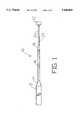
- FIG. 1is a side view of a core wire in accordance with of the present invention
- FIG. 2is a side view of a guidewire in accordance with the present invention employing the first and second helical coils spaced by a flexible sleeve.
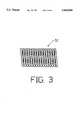
- FIG. 3is a view of a first or distal helical coil in accordance with the present invention.
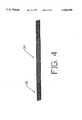
- FIG. 4is a view of a second or proximal helical coil in accordance with the present invention.
- FIG. 5is a view of the flexible spacer sleeve in accordance with the present invention.
- FIG. 6is a view of a pair of helical coils connected in an alternate manner in accordance with the present invention.
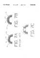
- FIGS. 7a, 7b and 7care views indicating the relative flexibility of the guidewire of the present invention over the prior art
- FIG. 8is a view of an alternate embodiment of the guidewire in accordance with the present invention.
- FIG. 9is a view of another alternate embodiment of a guidewire in accordance with the present invention.
- FIG. 1shows a first embodiment of a core wire 10 in accordance with the present invention.
- the guidewire of the preferred embodiments of the present inventionincludes a core wire, such as core wire 10 and helical coils and a sleeve (see FIG. 2 and associated text) attached at the distal end of the core wire.
- Core wire 10is preferably formed of a length (i.e. about 182 centimeters) of #304 stainless steel wire.
- Proximal portion 12is about 150 centimeters and has a constant diameter of about 0.010 inch to 0.018 inch.
- Portion 12may be completely coated with a lubricous coating such as PTFE (polytetrafluoroethylene) to lessen friction between the lumen wall of a catheter and the guidewire.
- a distal portion of core wire 10includes a tapered portion 14, an isodiametric portion 16, a second tapered portion 18, a second isodiametric portion 24, and a tapered portion 20. The distal portion is formed by centerless grinding of the stainless steel wire.
- a distal portion of portion 20may be flattened into a ribbon shape.
- Isodiametric portion 16has a diameter of about 0.006 inch.
- a distal tip 22has a diameter of about that of proximal portion 12. Tip 22 is used for terminating the distal portion of the helix
- FIG. 2is a side view of an assembled guidewire of this invention employing core wire 10 (see also FIG. 1) and distal and proximal helical coils 32 and 34, respectively.
- a ball tip 39is formed by soldering or brazing or otherwise attaching distal helix 32 and distal tip 22 of core wire 10, thus permanently joining them.
- Proximal section 36 of proximal coil 34is similarly soldered or brazed or otherwise attached to section 14 of core wire 10. Alternately, either or both of these connections can be made by a flexible adhesive.
- the distal end of helix 34, and the proximal end of helix 32are shown attached to core wire 10.
- the attachmentis preferably made by flexible adhesive.
- Coils 32 and 34preferably have differing radiopacity by, for example, forming coil 32 from platinum and coil 34 from stainless steel.
- a sleeve 37 disposed between coils 32 and 34has low radiopacity such that a space is left between the two helical coils, such that a dark spot will appear between the coils 32 and 34 during fluoroscopy.
- Coils 32 and 34can be coated with silicone.
- the position of the dark spotcan be correlated with the position of the bright spot on most intraluminal catheters that will be positioned by the guidewire of the present invention, such bright spots being well known and widely used by those skilled in the art.
- the correlationallowing the operator to determine the relative position of the guidewire and the catheter.
- FIG. 3is a plan view of a first helical coil or distal helix 32 intended to be attached to core wire 10.
- distal helix 32is a single coil of 14 k gold wire having a circular cross section.
- Other similarly radiopaque materialssuch as platinum may be used to form coil 32.
- the wirehas a diameter of about 0.0025 inch and the completed helix has an outside diameter approximately equal to the diameter of proximal portion 12.
- the coils of helix 32may be adjacent or in spaced relation. Increased spacing between the coils generally results in a coil 32 having increased transverse flexibility.
- FIG. 4is a plan view of a second helical coil or proximal helix 34.
- Coil 34can, for most of its length, have a closed winding.
- a proximal end 36 of coil 34is preferably a spaced winding coil for sufficient length to provide for attachment of end 36 to core wire 10.
- Coil 34is preferably made of #304 stainless steel of a circular cross section. It is preferable that the material used for coil 34 have a significantly different degree of radiopacity than does coil 32; such as the difference between platinum and stainless steel as suggested above.
- the platinum coilcan create a bright image under fluoroscopy whereas the stainless steel coil creates a ghost image.
- coils 32 and 34may be formed from wires having different diameters and flexibility characteristics as well known in the art. For example, a smaller diameter wire made from the same material as a larger diameter wire would be relatively more flexible than the larger diameter wire.
- FIG. 5shows a view of a sleeve 37.
- Sleeve 37is intended to fit around core wire 10 between coils 32 and 34.
- Sleeve 37can be made of a heat shrinkable, flexible material, such as PTFE (polytetrafluoroethylene), FEP (fluorinated ethylene propylene) or POC (polyolefin copolymer).
- PTFEpolytetrafluoroethylene
- FEPfluorinated ethylene propylene
- POCpolyolefin copolymer
- FIG. 6is a view of another embodiment of the present invention showing a pair of helical coils 32 and 34 mounted around a portion of core wire 10. Coils 32 and 34 are shown attached to core wire 10 simply by an elastic adhesive 45 without the use of a sleeve such as sleeve 37.
- FIGS. 7a, 7b and 7care schematic representations of the pair of coils 32 and 34 of FIG. 6 showing the difference between the attachment means of this invention and that of the prior art.
- FIG. 7adepicts a pair of coils 32a and 34a which have been interconnected by a prior art medium 46.
- Prior art medium 46could be solder or any other non-flexible form of attachment.
- the stiff connection 46causes a "flat" section 50 along the surface of connected coils 32a and 34a. This undesirable deformation of the bend is caused because the stiff connection 46 prevents the free bending of a plurality of adjacent turns on each of helical coils 32a and 34a. It is apparent that this flat spot 50 may interfere with the desired trackability of a guidewire through a lumen because the flat spot can cause the guidewire to prolapse when entering a side branch vessel.
- FIG. 7bdepicts a pair of helical coils 32b and 34b which are attached at one end by flexible adhesive 45.
- adhesive 45As can be seen when coils 32b and 34b are bent, the adjacent coils affixed by adhesive 45 are allowed to flex relative to one another and the result is a bent area 60 that is highly preferable to the flat area 50 of FIG. 7a.
- Coils 32b and 34bare preferably independently connected to the core wire (not shown) by adhesive 45.
- Attachment medium 45is preferably UV adhesive such as epoxy or acrylite.
- FIG. 8is a view of an alternate embodiment of a guidewire 100 in accordance with the present invention.
- Guidewire 100includes a core wire 102.
- Core wire 102can be the same as core wire 10 described above.
- Core wire 102includes a proximal isodiametric portion 103 which can be coated with a lubricous coating such as PTFE to lessen friction between the lumen wall of a catheter and guidewire 100.
- Core wire 102also includes a distal section 105 including a plurality of tapered sections and isodiametric portions.
- a distal coil 106 having a proximal end and a distal endis connected at its distal end to the extreme distal end of core wire 102.
- a ball tip 107is formed by soldering, brazing, welding or the like to form the connection between the distal end of distal coil 106 and core wire 102.
- Distal coil 106may be formed from the same materials as distal coil 32 described above. Like any of the coils disclosed herein, coil 106 can be covered with a silicone or hydrophilic coating.
- Guidewire 100also includes a proximal coil 108.
- Proximal coil 108extends around a portion of the distal portion 105 of core wire 102 proximal of distal coil 106.
- Proximal coil 108includes a proximal end and a distal end, the proximal end being fixably attached to the proximal most tapered section of distal section 105.
- the proximal end of proximal coil 108can be attached to core wire 102 by a medium 110 which can be solder, braze or any adhesive such as a UV adhesive.
- Proximal coil 108is preferably formed from stainless steel, but may be formed from any suitably durable biocompatible material.
- a sleeve 112is preferably disposed around core wire 102 between distal coil 106 and proximal coil 108.
- Sleeve 112can be formed from the same materials as sleeve 37 described above and can be used in the same way as sleeve 37.
- the proximal end of distal coil 106 and the distal end of proximal coil 108are fixably attached to core wire 102 by bonding mediums 114 and 116, respectively.
- Bonding medium 114 and 116can be solder, braze or an adhesive such as a UV adhesive.
- a plurality of radiopaque solder bands 118can be disposed around distal portion 105 of core wire 102 along a length of proximal coil 108.
- the solder forming bands 118is preferably silver/tin or gold/tin solder. Although other substantially radiopaque, biocompatible solders can be used.
- the spacing of marker bands 118can be calibrated to correspond to a length measurement along core wire 102. If the spacing of bands 118 is calibrated to measure length, bands 118 can be used to make intraluminal measurements under fluoroscopy. Bands 118 can also be located across a lesion by locating the lesion by angiography and placing the portion of guidewire 100, including bands 118 across that location. If bands 118 are held in place across the lesion, intravascular devices such as angioplasty balloons and stents may be readily advanced along guidewire 100 and located across the lesion by reference to bands 118.
- FIG. 9shows a guidewire 200 including a core wire 202.
- Core wire 202can be the same as core wire 10 described above or may be modified as described below.
- Core wire 202includes a proximal portion 204 and a distal portion 206.
- Distal portion 206can include several tapered portions and isodiametric portions.
- Proximal portion 204 and distal portion 206can be the same as the proximal and distal portions of core wire 10 as described above.
- Distal portion 206can be modified as described below.
- Guidewire 200preferably includes a coil 208 disposed around an extreme distal portion of core wire 202.
- Coil 208can be the same as distal coils 32 and 106 described above.
- the distal end of coil 208is fixedly attached to the extreme distal end of core wire 102 in the same manner as coils 32 and 106 are attached to core wires 10 and 102, respectively, to form a ball tip 210.
- a metallic sleeve 212is preferably disposed around a portion of core wire distal portion 206 proximally of coil 208.
- Sleeve 212is preferably formed from a nitinol hypotube. In addition to nitinol, other highly resilient metals may be used to form sleeve 212.
- Metallic sleeve 212must be flexible enough to allow guidewire 200 to be steerable through a tortuous vascular lumen, and resilient enough to avoid permanent kinking.
- Sleeve 212can be coated with PTFE, silicone or a hydrophilic coating.
- Proximal core wire portion 204 and sleeve 212preferably have the same outside diameters.
- the proximal most tapered portion 214can have a reduced diameter at transition 216, relative to proximal portion 204.
- the reduction in diameteris preferably two times the wall thickness of metallic sleeve 212.
- a bridge tube 218is preferably disposed around a portion of core wire 202 at the proximal end of coil 208 and the distal end of metallic sleeve 212. Placement of bridge tube 218 in this location is intended to urge coil 208 and sleeve 212 into coaxial alignment around core wire 202.
- the proximal end of coil 208 and the distal end of sleeve 212are preferably fixedly connected to bridge tube 218 and core wire 202 by bonding medium 220 which can be a solder, braze or an adhesive such as a UV adhesive.
Landscapes
- Health & Medical Sciences (AREA)
- Life Sciences & Earth Sciences (AREA)
- Engineering & Computer Science (AREA)
- General Health & Medical Sciences (AREA)
- Biophysics (AREA)
- Veterinary Medicine (AREA)
- Biomedical Technology (AREA)
- Heart & Thoracic Surgery (AREA)
- Public Health (AREA)
- Animal Behavior & Ethology (AREA)
- Anesthesiology (AREA)
- Hematology (AREA)
- Pulmonology (AREA)
- Medical Informatics (AREA)
- Physics & Mathematics (AREA)
- High Energy & Nuclear Physics (AREA)
- Nuclear Medicine, Radiotherapy & Molecular Imaging (AREA)
- Optics & Photonics (AREA)
- Pathology (AREA)
- Radiology & Medical Imaging (AREA)
- Molecular Biology (AREA)
- Surgery (AREA)
- Media Introduction/Drainage Providing Device (AREA)
Abstract
Description
Claims (23)
Priority Applications (1)
| Application Number | Priority Date | Filing Date | Title |
|---|---|---|---|
| US08/425,933US5666969A (en) | 1994-05-18 | 1995-04-20 | Guidewire having multiple radioscopic coils |
Applications Claiming Priority (2)
| Application Number | Priority Date | Filing Date | Title |
|---|---|---|---|
| US08/245,726US5497783A (en) | 1994-05-18 | 1994-05-18 | Guidewire having radioscopic tip |
| US08/425,933US5666969A (en) | 1994-05-18 | 1995-04-20 | Guidewire having multiple radioscopic coils |
Related Parent Applications (1)
| Application Number | Title | Priority Date | Filing Date |
|---|---|---|---|
| US08/245,726Continuation-In-PartUS5497783A (en) | 1994-05-18 | 1994-05-18 | Guidewire having radioscopic tip |
Publications (1)
| Publication Number | Publication Date |
|---|---|
| US5666969Atrue US5666969A (en) | 1997-09-16 |
Family
ID=46250322
Family Applications (1)
| Application Number | Title | Priority Date | Filing Date |
|---|---|---|---|
| US08/425,933Expired - LifetimeUS5666969A (en) | 1994-05-18 | 1995-04-20 | Guidewire having multiple radioscopic coils |
Country Status (1)
| Country | Link |
|---|---|
| US (1) | US5666969A (en) |
Cited By (76)
| Publication number | Priority date | Publication date | Assignee | Title |
|---|---|---|---|---|
| US5876783A (en)* | 1995-06-20 | 1999-03-02 | The Microspring Company, Inc. | Radiopaque medical devices |
| WO1999019018A3 (en)* | 1997-10-16 | 1999-07-29 | Scimed Life Systems Inc | Guide wire tip |
| US5931830A (en)* | 1995-12-07 | 1999-08-03 | Sarcos L.C. | Hollow coil guide wire apparatus for catheters |
| US5951496A (en)* | 1996-05-03 | 1999-09-14 | Schneider (Europe) Gmbh | Guide wire and method of producing a guide wire |
| US6036682A (en) | 1997-12-02 | 2000-03-14 | Scimed Life Systems, Inc. | Catheter having a plurality of integral radiopaque bands |
| US6039699A (en)* | 1996-01-22 | 2000-03-21 | Cordis Corporation | Stiff catheter guidewire with flexible distal portion |
| EP1042998A3 (en)* | 1999-04-07 | 2001-01-17 | Medtronic Ave, Inc. | Endolumenal prosthesis delivery assembly and method of use |
| JP2002143320A (en)* | 2000-11-15 | 2002-05-21 | Kawasumi Lab Inc | Guide wire |
| US6428489B1 (en) | 1995-12-07 | 2002-08-06 | Precision Vascular Systems, Inc. | Guidewire system |
| US6440088B1 (en) | 1996-05-24 | 2002-08-27 | Precision Vascular Systems, Inc. | Hybrid catheter guide wire apparatus and method |
| US20030069522A1 (en)* | 1995-12-07 | 2003-04-10 | Jacobsen Stephen J. | Slotted medical device |
| US6579246B2 (en) | 1999-12-22 | 2003-06-17 | Sarcos, Lc | Coronary guidewire system |
| US6673025B1 (en) | 1993-12-01 | 2004-01-06 | Advanced Cardiovascular Systems, Inc. | Polymer coated guidewire |
| US6712842B1 (en)* | 1999-10-12 | 2004-03-30 | Allan Will | Methods and devices for lining a blood vessel and opening a narrowed region of a blood vessel |
| US20040064069A1 (en)* | 2002-09-30 | 2004-04-01 | Reynolds Brian R. | Medical device with support member |
| US20040122340A1 (en)* | 2002-12-23 | 2004-06-24 | Anthony Vrba | Guidewire tip construction |
| US20040127820A1 (en)* | 2001-09-05 | 2004-07-01 | Clayman Ralph V. | Guidewire |
| US20040167442A1 (en)* | 2003-02-26 | 2004-08-26 | Shireman Brice L. | Elongated intracorporal medical device |
| US20040167439A1 (en)* | 2003-02-26 | 2004-08-26 | Sharrow James S. | Guidewire having textured proximal portion |
| US20040167440A1 (en)* | 2003-02-26 | 2004-08-26 | Sharrow James S. | Multiple diameter guidewire |
| US20040167438A1 (en)* | 2003-02-26 | 2004-08-26 | Sharrow James S. | Reinforced medical device |
| US20040181175A1 (en)* | 1999-04-30 | 2004-09-16 | Clayman Ralph V. | Guidewire |
| US20040193140A1 (en)* | 2003-03-27 | 2004-09-30 | Scimed Life Systems,Inc. | Medical device |
| US20050038359A1 (en)* | 2003-07-17 | 2005-02-17 | Terumo Kabushiki Kaisha | Guide wire |
| US20050065456A1 (en)* | 2003-09-22 | 2005-03-24 | Scimed Life Systems, Inc. | Guidewire with reinforcing member |
| US20050075582A1 (en)* | 1997-03-06 | 2005-04-07 | Scimed Life Systems, Inc. | Guide wire with hydrophilically coated tip |
| US20050096567A1 (en)* | 2003-10-30 | 2005-05-05 | Scimed Life Systems, Inc. | Guidewire having an embedded matrix polymer |
| US20050096665A1 (en)* | 2003-10-30 | 2005-05-05 | Scimed Life Systems, Inc. | Guidewire having a helically contoured portion |
| US20050203442A1 (en)* | 2004-03-15 | 2005-09-15 | Asahi Intecc Co., Ltd. | Medical guide wire |
| US20060241419A1 (en)* | 2005-03-02 | 2006-10-26 | Terumo Kabushiki Kaisha | Guide wire |
| US20060264904A1 (en)* | 2005-05-09 | 2006-11-23 | Kerby Walter L | Medical device |
| US7169118B2 (en) | 2003-02-26 | 2007-01-30 | Scimed Life Systems, Inc. | Elongate medical device with distal cap |
| US20080015499A1 (en)* | 2002-08-06 | 2008-01-17 | Boris Warnack | Balloon Catheter With Radiopaque Marker |
| US7455646B2 (en) | 1997-06-04 | 2008-11-25 | Advanced Cardiovascular Systems, Inc. | Polymer coated guide wire |
| US7494474B2 (en) | 1997-06-04 | 2009-02-24 | Advanced Cardiovascular Systems, Inc. | Polymer coated guidewire |
| US20090292225A1 (en)* | 2008-05-21 | 2009-11-26 | Boston Scientific Scimed, Inc. | Medical device including a braid for crossing an occlusion in a vessel |
| US20090299332A1 (en)* | 2008-05-30 | 2009-12-03 | Boston Scientific Scimed, Inc. | Medical device including a polymer sleeve and a coil wound into the polymer sleeve |
| US7632242B2 (en) | 2004-12-09 | 2009-12-15 | Boston Scientific Scimed, Inc. | Catheter including a compliant balloon |
| US20090312670A1 (en)* | 2008-06-13 | 2009-12-17 | Cook Incorporated | Wire guide having a rib for coil attachment |
| US7824345B2 (en) | 2003-12-22 | 2010-11-02 | Boston Scientific Scimed, Inc. | Medical device with push force limiter |
| US7841994B2 (en) | 2007-11-02 | 2010-11-30 | Boston Scientific Scimed, Inc. | Medical device for crossing an occlusion in a vessel |
| US7850623B2 (en) | 2005-10-27 | 2010-12-14 | Boston Scientific Scimed, Inc. | Elongate medical device with continuous reinforcement member |
| US7878984B2 (en) | 2002-07-25 | 2011-02-01 | Boston Scientific Scimed, Inc. | Medical device for navigation through anatomy and method of making same |
| US7914467B2 (en) | 2002-07-25 | 2011-03-29 | Boston Scientific Scimed, Inc. | Tubular member having tapered transition for use in a medical device |
| US20110308367A1 (en)* | 2008-08-11 | 2011-12-22 | Hayner Louis R | Catheter Cutting Tool |
| US8105246B2 (en) | 2007-08-03 | 2012-01-31 | Boston Scientific Scimed, Inc. | Elongate medical device having enhanced torque and methods thereof |
| US20120065623A1 (en)* | 2010-09-14 | 2012-03-15 | Abbott Cardiovascular Systems Inc. | Guide wire with soldered multilayer coil member |
| US8137293B2 (en) | 2009-11-17 | 2012-03-20 | Boston Scientific Scimed, Inc. | Guidewires including a porous nickel-titanium alloy |
| US20120197159A1 (en)* | 2011-01-28 | 2012-08-02 | Asahi Intecc Co., Ltd. | Guidewire |
| US20130006149A1 (en)* | 2011-06-29 | 2013-01-03 | Abbott Cardiovascular Systems | Guide Wire Device Including a Solderable Linear Elastic Nickel-Titanium Distal End Section and Methods Of Preparation Therefor |
| US8377035B2 (en) | 2003-01-17 | 2013-02-19 | Boston Scientific Scimed, Inc. | Unbalanced reinforcement members for medical device |
| US8376961B2 (en) | 2008-04-07 | 2013-02-19 | Boston Scientific Scimed, Inc. | Micromachined composite guidewire structure with anisotropic bending properties |
| US8409114B2 (en) | 2007-08-02 | 2013-04-02 | Boston Scientific Scimed, Inc. | Composite elongate medical device including distal tubular member |
| US8449526B2 (en) | 2001-07-05 | 2013-05-28 | Boston Scientific Scimed, Inc. | Torqueable soft tip medical device and method of usage |
| EP2633878A1 (en)* | 2012-02-28 | 2013-09-04 | Covidien LP | Intravascular guidewire |
| US8535243B2 (en) | 2008-09-10 | 2013-09-17 | Boston Scientific Scimed, Inc. | Medical devices and tapered tubular members for use in medical devices |
| US8551021B2 (en) | 2010-03-31 | 2013-10-08 | Boston Scientific Scimed, Inc. | Guidewire with an improved flexural rigidity profile |
| US8551020B2 (en) | 2006-09-13 | 2013-10-08 | Boston Scientific Scimed, Inc. | Crossing guidewire |
| US8556914B2 (en) | 2006-12-15 | 2013-10-15 | Boston Scientific Scimed, Inc. | Medical device including structure for crossing an occlusion in a vessel |
| US20140058257A1 (en)* | 2012-08-23 | 2014-02-27 | Volcano Corporation | Device, System, and Method Utilizing a Radiopaque Coil for Anatomical Lesion Length Estimation |
| US8795254B2 (en) | 2008-12-10 | 2014-08-05 | Boston Scientific Scimed, Inc. | Medical devices with a slotted tubular member having improved stress distribution |
| US8795202B2 (en) | 2011-02-04 | 2014-08-05 | Boston Scientific Scimed, Inc. | Guidewires and methods for making and using the same |
| US8821477B2 (en) | 2007-08-06 | 2014-09-02 | Boston Scientific Scimed, Inc. | Alternative micromachined structures |
| US9072874B2 (en) | 2011-05-13 | 2015-07-07 | Boston Scientific Scimed, Inc. | Medical devices with a heat transfer region and a heat sink region and methods for manufacturing medical devices |
| US9445784B2 (en) | 2005-09-22 | 2016-09-20 | Boston Scientific Scimed, Inc | Intravascular ultrasound catheter |
| US9808595B2 (en) | 2007-08-07 | 2017-11-07 | Boston Scientific Scimed, Inc | Microfabricated catheter with improved bonding structure |
| US9901706B2 (en) | 2014-04-11 | 2018-02-27 | Boston Scientific Scimed, Inc. | Catheters and catheter shafts |
| US10124437B2 (en) | 2013-08-19 | 2018-11-13 | Covidien Lp | Laser welding of nickel titanium alloys |
| US10413273B2 (en) | 2014-05-20 | 2019-09-17 | Koninklijke Philips N.V. | Intravascular devices, systems, and methods having drive cables with a lubricious coating and/or radiopaque markers |
| US11351048B2 (en) | 2015-11-16 | 2022-06-07 | Boston Scientific Scimed, Inc. | Stent delivery systems with a reinforced deployment sheath |
| US11452533B2 (en) | 2019-01-10 | 2022-09-27 | Abbott Cardiovascular Systems Inc. | Guide wire tip having roughened surface |
| US11779477B2 (en) | 2010-11-17 | 2023-10-10 | Abbott Cardiovascular Systems, Inc. | Radiopaque intraluminal stents |
| US12151049B2 (en) | 2019-10-14 | 2024-11-26 | Abbott Cardiovascular Systems, Inc. | Methods for manufacturing radiopaque intraluminal stents comprising cobalt-based alloys with supersaturated tungsten content |
| US12171917B1 (en) | 2024-01-08 | 2024-12-24 | Imperative Care, Inc. | Devices for blood capture and reintroduction during aspiration procedure |
| US12343479B2 (en) | 2016-02-24 | 2025-07-01 | Incept, Llc | Neurovascular catheter |
| US12350443B2 (en) | 2019-03-29 | 2025-07-08 | Incept, Llc | Enhanced flexibility neurovascular catheter |
Citations (2)
| Publication number | Priority date | Publication date | Assignee | Title |
|---|---|---|---|---|
| US4964409A (en)* | 1989-05-11 | 1990-10-23 | Advanced Cardiovascular Systems, Inc. | Flexible hollow guiding member with means for fluid communication therethrough |
| US5209730A (en)* | 1989-12-19 | 1993-05-11 | Scimed Life Systems, Inc. | Method for placement of a balloon dilatation catheter across a stenosis and apparatus therefor |
- 1995
- 1995-04-20USUS08/425,933patent/US5666969A/ennot_activeExpired - Lifetime
Patent Citations (2)
| Publication number | Priority date | Publication date | Assignee | Title |
|---|---|---|---|---|
| US4964409A (en)* | 1989-05-11 | 1990-10-23 | Advanced Cardiovascular Systems, Inc. | Flexible hollow guiding member with means for fluid communication therethrough |
| US5209730A (en)* | 1989-12-19 | 1993-05-11 | Scimed Life Systems, Inc. | Method for placement of a balloon dilatation catheter across a stenosis and apparatus therefor |
Cited By (136)
| Publication number | Priority date | Publication date | Assignee | Title |
|---|---|---|---|---|
| US6673025B1 (en) | 1993-12-01 | 2004-01-06 | Advanced Cardiovascular Systems, Inc. | Polymer coated guidewire |
| US5876783A (en)* | 1995-06-20 | 1999-03-02 | The Microspring Company, Inc. | Radiopaque medical devices |
| US5931830A (en)* | 1995-12-07 | 1999-08-03 | Sarcos L.C. | Hollow coil guide wire apparatus for catheters |
| US20030069522A1 (en)* | 1995-12-07 | 2003-04-10 | Jacobsen Stephen J. | Slotted medical device |
| US6428489B1 (en) | 1995-12-07 | 2002-08-06 | Precision Vascular Systems, Inc. | Guidewire system |
| US7914466B2 (en) | 1995-12-07 | 2011-03-29 | Precision Vascular Systems, Inc. | Medical device with collapse-resistant liner and method of making same |
| US6039699A (en)* | 1996-01-22 | 2000-03-21 | Cordis Corporation | Stiff catheter guidewire with flexible distal portion |
| US5951496A (en)* | 1996-05-03 | 1999-09-14 | Schneider (Europe) Gmbh | Guide wire and method of producing a guide wire |
| US6440088B1 (en) | 1996-05-24 | 2002-08-27 | Precision Vascular Systems, Inc. | Hybrid catheter guide wire apparatus and method |
| US7115101B2 (en)* | 1997-03-06 | 2006-10-03 | Scimed Life Systems, Inc. | Guide wire with hydrophilically coated tip |
| US20050075582A1 (en)* | 1997-03-06 | 2005-04-07 | Scimed Life Systems, Inc. | Guide wire with hydrophilically coated tip |
| US7494474B2 (en) | 1997-06-04 | 2009-02-24 | Advanced Cardiovascular Systems, Inc. | Polymer coated guidewire |
| US7455646B2 (en) | 1997-06-04 | 2008-11-25 | Advanced Cardiovascular Systems, Inc. | Polymer coated guide wire |
| US6132388A (en)* | 1997-10-16 | 2000-10-17 | Scimed Life Systems, Inc. | Guide wire tip |
| US6475167B1 (en) | 1997-10-16 | 2002-11-05 | Scimed Life Systems, Inc. | Guide wire tip |
| WO1999019018A3 (en)* | 1997-10-16 | 1999-07-29 | Scimed Life Systems Inc | Guide wire tip |
| US6036682A (en) | 1997-12-02 | 2000-03-14 | Scimed Life Systems, Inc. | Catheter having a plurality of integral radiopaque bands |
| US6319275B1 (en) | 1999-04-07 | 2001-11-20 | Medtronic Ave, Inc. | Endolumenal prosthesis delivery assembly and method of use |
| EP1042998A3 (en)* | 1999-04-07 | 2001-01-17 | Medtronic Ave, Inc. | Endolumenal prosthesis delivery assembly and method of use |
| US20040181175A1 (en)* | 1999-04-30 | 2004-09-16 | Clayman Ralph V. | Guidewire |
| US6712842B1 (en)* | 1999-10-12 | 2004-03-30 | Allan Will | Methods and devices for lining a blood vessel and opening a narrowed region of a blood vessel |
| US6579246B2 (en) | 1999-12-22 | 2003-06-17 | Sarcos, Lc | Coronary guidewire system |
| JP2002143320A (en)* | 2000-11-15 | 2002-05-21 | Kawasumi Lab Inc | Guide wire |
| US8449526B2 (en) | 2001-07-05 | 2013-05-28 | Boston Scientific Scimed, Inc. | Torqueable soft tip medical device and method of usage |
| US20040127820A1 (en)* | 2001-09-05 | 2004-07-01 | Clayman Ralph V. | Guidewire |
| US8936558B2 (en) | 2002-07-25 | 2015-01-20 | Precision Vascular Systems, Inc. | Medical device for navigation through anatomy and method of making same |
| US8257279B2 (en) | 2002-07-25 | 2012-09-04 | Boston Scientific Scimed, Inc. | Medical device for navigation through anatomy and method of making same |
| US8939916B2 (en) | 2002-07-25 | 2015-01-27 | Precision Vascular Systems, Inc. | Medical device for navigation through anatomy and method of making same |
| US7878984B2 (en) | 2002-07-25 | 2011-02-01 | Boston Scientific Scimed, Inc. | Medical device for navigation through anatomy and method of making same |
| US8932235B2 (en) | 2002-07-25 | 2015-01-13 | Precision Vascular Systems, Inc. | Medical device for navigation through anatomy and method of making same |
| US8915865B2 (en) | 2002-07-25 | 2014-12-23 | Precision Vascular Systems, Inc. | Medical device for navigation through anatomy and method of making same |
| US7914467B2 (en) | 2002-07-25 | 2011-03-29 | Boston Scientific Scimed, Inc. | Tubular member having tapered transition for use in a medical device |
| US8900163B2 (en) | 2002-07-25 | 2014-12-02 | Precision Vascular Systems, Inc. | Medical device for navigation through anatomy and method of making same |
| US8870790B2 (en) | 2002-07-25 | 2014-10-28 | Boston Scientific Scimed, Inc. | Medical device for navigation through anatomy and method of making same |
| US8048004B2 (en) | 2002-07-25 | 2011-11-01 | Precision Vascular Systems, Inc. | Medical device for navigation through anatomy and method of making same |
| US20080015499A1 (en)* | 2002-08-06 | 2008-01-17 | Boris Warnack | Balloon Catheter With Radiopaque Marker |
| US8251949B2 (en)* | 2002-08-06 | 2012-08-28 | Abbott Laboratories | Balloon catheter with radiopaque marker |
| US20040064069A1 (en)* | 2002-09-30 | 2004-04-01 | Reynolds Brian R. | Medical device with support member |
| WO2004030742A1 (en)* | 2002-09-30 | 2004-04-15 | Boston Scientific Limited | Medical device with support member |
| US7077811B2 (en) | 2002-12-23 | 2006-07-18 | Scimed Life Systems, Inc. | Guidewire tip construction |
| US20060235337A1 (en)* | 2002-12-23 | 2006-10-19 | Scimed Life Systems, Inc. | Guidewire tip construction |
| US7998088B2 (en) | 2002-12-23 | 2011-08-16 | Boston Scientifc Scimed, Inc. | Guidewire tip construction |
| US20040122340A1 (en)* | 2002-12-23 | 2004-06-24 | Anthony Vrba | Guidewire tip construction |
| US8377035B2 (en) | 2003-01-17 | 2013-02-19 | Boston Scientific Scimed, Inc. | Unbalanced reinforcement members for medical device |
| US8222566B2 (en) | 2003-02-26 | 2012-07-17 | Boston Scientific Scimed, Inc. | Elongated intracorporal medical device |
| US20040167443A1 (en)* | 2003-02-26 | 2004-08-26 | Scimed Life Systems, Inc. | Elongated intracorporal medical device |
| US7316656B2 (en)* | 2003-02-26 | 2008-01-08 | Boston Scientific Scimed, Inc. | Elongated intracorporal medical device |
| US20070123805A1 (en)* | 2003-02-26 | 2007-05-31 | Boston Scientific Scimed, Inc. | Elongated intracorporal medical device |
| US20040167442A1 (en)* | 2003-02-26 | 2004-08-26 | Shireman Brice L. | Elongated intracorporal medical device |
| US7182735B2 (en) | 2003-02-26 | 2007-02-27 | Scimed Life Systems, Inc. | Elongated intracorporal medical device |
| US8167821B2 (en) | 2003-02-26 | 2012-05-01 | Boston Scientific Scimed, Inc. | Multiple diameter guidewire |
| US20050145307A1 (en)* | 2003-02-26 | 2005-07-07 | Shireman Brice L. | Elongated intracorporal medical device |
| US7169118B2 (en) | 2003-02-26 | 2007-01-30 | Scimed Life Systems, Inc. | Elongate medical device with distal cap |
| US8022331B2 (en) | 2003-02-26 | 2011-09-20 | Boston Scientific Scimed, Inc. | Method of making elongated medical devices |
| US20040167438A1 (en)* | 2003-02-26 | 2004-08-26 | Sharrow James S. | Reinforced medical device |
| US20040167440A1 (en)* | 2003-02-26 | 2004-08-26 | Sharrow James S. | Multiple diameter guidewire |
| US20040167439A1 (en)* | 2003-02-26 | 2004-08-26 | Sharrow James S. | Guidewire having textured proximal portion |
| US8048060B2 (en) | 2003-03-27 | 2011-11-01 | Boston Scientific Scimed, Inc. | Medical device |
| US9023011B2 (en) | 2003-03-27 | 2015-05-05 | Boston Scientific Scimed, Inc. | Medical device |
| US8636716B2 (en) | 2003-03-27 | 2014-01-28 | Boston Scientific Scimed, Inc. | Medical device |
| US10207077B2 (en) | 2003-03-27 | 2019-02-19 | Boston Scientific Scimed, Inc. | Medical device |
| US7001369B2 (en) | 2003-03-27 | 2006-02-21 | Scimed Life Systems, Inc. | Medical device |
| US9592363B2 (en) | 2003-03-27 | 2017-03-14 | Boston Scientific Scimed, Inc. | Medical device |
| US8182465B2 (en) | 2003-03-27 | 2012-05-22 | Boston Scientific Scimed, Inc. | Medical device |
| US7540865B2 (en) | 2003-03-27 | 2009-06-02 | Boston Scientific Scimed, Inc. | Medical device |
| US20040193140A1 (en)* | 2003-03-27 | 2004-09-30 | Scimed Life Systems,Inc. | Medical device |
| US20050038359A1 (en)* | 2003-07-17 | 2005-02-17 | Terumo Kabushiki Kaisha | Guide wire |
| JP2005046603A (en)* | 2003-07-17 | 2005-02-24 | Terumo Corp | Guide wire |
| US7722552B2 (en) | 2003-07-17 | 2010-05-25 | Terumo Kabushiki Kaisha | Guide wire |
| US7785273B2 (en) | 2003-09-22 | 2010-08-31 | Boston Scientific Scimed, Inc. | Guidewire with reinforcing member |
| US20050065456A1 (en)* | 2003-09-22 | 2005-03-24 | Scimed Life Systems, Inc. | Guidewire with reinforcing member |
| US7553287B2 (en) | 2003-10-30 | 2009-06-30 | Boston Scientific Scimed, Inc. | Guidewire having an embedded matrix polymer |
| US20050096665A1 (en)* | 2003-10-30 | 2005-05-05 | Scimed Life Systems, Inc. | Guidewire having a helically contoured portion |
| US20050096567A1 (en)* | 2003-10-30 | 2005-05-05 | Scimed Life Systems, Inc. | Guidewire having an embedded matrix polymer |
| US7824345B2 (en) | 2003-12-22 | 2010-11-02 | Boston Scientific Scimed, Inc. | Medical device with push force limiter |
| US20050203442A1 (en)* | 2004-03-15 | 2005-09-15 | Asahi Intecc Co., Ltd. | Medical guide wire |
| US7278974B2 (en)* | 2004-03-15 | 2007-10-09 | Asahi In Tecc Co., Ltd. | Medical guide wire |
| US7632242B2 (en) | 2004-12-09 | 2009-12-15 | Boston Scientific Scimed, Inc. | Catheter including a compliant balloon |
| US8540668B2 (en) | 2004-12-09 | 2013-09-24 | Boston Scientific Scimed, Inc. | Catheter including a compliant balloon |
| US8021329B2 (en) | 2004-12-09 | 2011-09-20 | Boston Scientific Scimed, Inc., | Catheter including a compliant balloon |
| US9433762B2 (en) | 2004-12-09 | 2016-09-06 | Boston Scientific Scimed, Inc. | Catheter including a compliant balloon |
| US20060241419A1 (en)* | 2005-03-02 | 2006-10-26 | Terumo Kabushiki Kaisha | Guide wire |
| US20060264904A1 (en)* | 2005-05-09 | 2006-11-23 | Kerby Walter L | Medical device |
| US9445784B2 (en) | 2005-09-22 | 2016-09-20 | Boston Scientific Scimed, Inc | Intravascular ultrasound catheter |
| US8231551B2 (en) | 2005-10-27 | 2012-07-31 | Boston Scientific Scimed, Inc. | Elongate medical device with continuous reinforcement member |
| US7850623B2 (en) | 2005-10-27 | 2010-12-14 | Boston Scientific Scimed, Inc. | Elongate medical device with continuous reinforcement member |
| US8551020B2 (en) | 2006-09-13 | 2013-10-08 | Boston Scientific Scimed, Inc. | Crossing guidewire |
| US9375234B2 (en) | 2006-12-15 | 2016-06-28 | Boston Scientific Scimed, Inc. | Medical device including structure for crossing an occlusion in a vessel |
| US8556914B2 (en) | 2006-12-15 | 2013-10-15 | Boston Scientific Scimed, Inc. | Medical device including structure for crossing an occlusion in a vessel |
| US8409114B2 (en) | 2007-08-02 | 2013-04-02 | Boston Scientific Scimed, Inc. | Composite elongate medical device including distal tubular member |
| US8105246B2 (en) | 2007-08-03 | 2012-01-31 | Boston Scientific Scimed, Inc. | Elongate medical device having enhanced torque and methods thereof |
| US8821477B2 (en) | 2007-08-06 | 2014-09-02 | Boston Scientific Scimed, Inc. | Alternative micromachined structures |
| US9808595B2 (en) | 2007-08-07 | 2017-11-07 | Boston Scientific Scimed, Inc | Microfabricated catheter with improved bonding structure |
| US7841994B2 (en) | 2007-11-02 | 2010-11-30 | Boston Scientific Scimed, Inc. | Medical device for crossing an occlusion in a vessel |
| US8376961B2 (en) | 2008-04-07 | 2013-02-19 | Boston Scientific Scimed, Inc. | Micromachined composite guidewire structure with anisotropic bending properties |
| US20090292225A1 (en)* | 2008-05-21 | 2009-11-26 | Boston Scientific Scimed, Inc. | Medical device including a braid for crossing an occlusion in a vessel |
| US20090299332A1 (en)* | 2008-05-30 | 2009-12-03 | Boston Scientific Scimed, Inc. | Medical device including a polymer sleeve and a coil wound into the polymer sleeve |
| US8002715B2 (en) | 2008-05-30 | 2011-08-23 | Boston Scientific Scimed, Inc. | Medical device including a polymer sleeve and a coil wound into the polymer sleeve |
| US8777873B2 (en) | 2008-06-13 | 2014-07-15 | Cook Medical Technologies Llc | Wire guide having a rib for coil attachment |
| US20090312670A1 (en)* | 2008-06-13 | 2009-12-17 | Cook Incorporated | Wire guide having a rib for coil attachment |
| US8250960B2 (en)* | 2008-08-11 | 2012-08-28 | Cardiac Dimensions, Inc. | Catheter cutting tool |
| US20110308367A1 (en)* | 2008-08-11 | 2011-12-22 | Hayner Louis R | Catheter Cutting Tool |
| US8535243B2 (en) | 2008-09-10 | 2013-09-17 | Boston Scientific Scimed, Inc. | Medical devices and tapered tubular members for use in medical devices |
| US8795254B2 (en) | 2008-12-10 | 2014-08-05 | Boston Scientific Scimed, Inc. | Medical devices with a slotted tubular member having improved stress distribution |
| US8137293B2 (en) | 2009-11-17 | 2012-03-20 | Boston Scientific Scimed, Inc. | Guidewires including a porous nickel-titanium alloy |
| US8784337B2 (en) | 2010-03-31 | 2014-07-22 | Boston Scientific Scimed, Inc. | Catheter with an improved flexural rigidity profile |
| US8551021B2 (en) | 2010-03-31 | 2013-10-08 | Boston Scientific Scimed, Inc. | Guidewire with an improved flexural rigidity profile |
| US8480598B2 (en)* | 2010-09-14 | 2013-07-09 | Abbott Cardiovascular Systems Inc. | Guide wire with soldered multilayer coil member |
| US20120065623A1 (en)* | 2010-09-14 | 2012-03-15 | Abbott Cardiovascular Systems Inc. | Guide wire with soldered multilayer coil member |
| US11779477B2 (en) | 2010-11-17 | 2023-10-10 | Abbott Cardiovascular Systems, Inc. | Radiopaque intraluminal stents |
| US12150872B2 (en) | 2010-11-17 | 2024-11-26 | Abbott Cardiovascular Systems, Inc. | Radiopaque intraluminal stents |
| US8758269B2 (en)* | 2011-01-28 | 2014-06-24 | Asahi Intecc Co., Ltd. | Guidewire |
| US20120197159A1 (en)* | 2011-01-28 | 2012-08-02 | Asahi Intecc Co., Ltd. | Guidewire |
| US8795202B2 (en) | 2011-02-04 | 2014-08-05 | Boston Scientific Scimed, Inc. | Guidewires and methods for making and using the same |
| US9072874B2 (en) | 2011-05-13 | 2015-07-07 | Boston Scientific Scimed, Inc. | Medical devices with a heat transfer region and a heat sink region and methods for manufacturing medical devices |
| US9724494B2 (en)* | 2011-06-29 | 2017-08-08 | Abbott Cardiovascular Systems, Inc. | Guide wire device including a solderable linear elastic nickel-titanium distal end section and methods of preparation therefor |
| US11806488B2 (en) | 2011-06-29 | 2023-11-07 | Abbott Cardiovascular Systems, Inc. | Medical device including a solderable linear elastic nickel-titanium distal end section and methods of preparation therefor |
| US20130006149A1 (en)* | 2011-06-29 | 2013-01-03 | Abbott Cardiovascular Systems | Guide Wire Device Including a Solderable Linear Elastic Nickel-Titanium Distal End Section and Methods Of Preparation Therefor |
| EP2633878A1 (en)* | 2012-02-28 | 2013-09-04 | Covidien LP | Intravascular guidewire |
| US10029076B2 (en) | 2012-02-28 | 2018-07-24 | Covidien Lp | Intravascular guidewire |
| US10561473B2 (en) | 2012-08-23 | 2020-02-18 | Philips Image Guided Therapy Corporation | Device, system, and method utilizing a radiopaque element for anatomical lesion length estimation |
| US20140058257A1 (en)* | 2012-08-23 | 2014-02-27 | Volcano Corporation | Device, System, and Method Utilizing a Radiopaque Coil for Anatomical Lesion Length Estimation |
| US9743992B2 (en)* | 2012-08-23 | 2017-08-29 | Volcano Corporation | Device, system, and method utilizing a radiopaque coil for anatomical lesion length estimation |
| US11850102B2 (en) | 2012-08-23 | 2023-12-26 | Philips Image Guided Therapy Corporation | Device, system, and method utilizing a radiopaque element for anatomical lesion length estimation |
| US11950965B2 (en) | 2012-08-23 | 2024-04-09 | Philips Image Guided Therapy Corporation | Device, system, and method utilizing a radiopaque element for anatomical lesion length estimation |
| US12402971B2 (en) | 2012-08-23 | 2025-09-02 | Philips Image Guided Therapy Corporation | Device, system, and method utilizing a radiopaque element for anatomical lesion length estimation |
| US10124437B2 (en) | 2013-08-19 | 2018-11-13 | Covidien Lp | Laser welding of nickel titanium alloys |
| US9901706B2 (en) | 2014-04-11 | 2018-02-27 | Boston Scientific Scimed, Inc. | Catheters and catheter shafts |
| US10413273B2 (en) | 2014-05-20 | 2019-09-17 | Koninklijke Philips N.V. | Intravascular devices, systems, and methods having drive cables with a lubricious coating and/or radiopaque markers |
| US11351048B2 (en) | 2015-11-16 | 2022-06-07 | Boston Scientific Scimed, Inc. | Stent delivery systems with a reinforced deployment sheath |
| US12343479B2 (en) | 2016-02-24 | 2025-07-01 | Incept, Llc | Neurovascular catheter |
| US11452533B2 (en) | 2019-01-10 | 2022-09-27 | Abbott Cardiovascular Systems Inc. | Guide wire tip having roughened surface |
| US12137923B2 (en) | 2019-01-10 | 2024-11-12 | Abbott Cardiovascular Systems Inc. | Guide wire tip having roughened surface |
| US12350443B2 (en) | 2019-03-29 | 2025-07-08 | Incept, Llc | Enhanced flexibility neurovascular catheter |
| US12151049B2 (en) | 2019-10-14 | 2024-11-26 | Abbott Cardiovascular Systems, Inc. | Methods for manufacturing radiopaque intraluminal stents comprising cobalt-based alloys with supersaturated tungsten content |
| US12171917B1 (en) | 2024-01-08 | 2024-12-24 | Imperative Care, Inc. | Devices for blood capture and reintroduction during aspiration procedure |
Similar Documents
| Publication | Publication Date | Title |
|---|---|---|
| US5666969A (en) | Guidewire having multiple radioscopic coils | |
| US6039699A (en) | Stiff catheter guidewire with flexible distal portion | |
| US6132388A (en) | Guide wire tip | |
| US5497783A (en) | Guidewire having radioscopic tip | |
| US5682894A (en) | Guide wire | |
| US7153277B2 (en) | Composite medical device with markers | |
| CA2228346C (en) | Guidewire having a distal tip that can change its shape within a vessel | |
| US8414506B2 (en) | Composite guidewire | |
| CA2212275C (en) | Guidewire having a distal tip that can change its shape within a vessel | |
| US5267574A (en) | Guidewire with spring and a heat shrinkable connection | |
| US6056702A (en) | Guidewire with outer sheath | |
| US5640970A (en) | Guidewire having a controlled radiopacity tip | |
| USRE33911E (en) | Catheter guide wire with short spring tip and method of using the same | |
| US5259393A (en) | Guidewire having controlled radiopacity tip | |
| AU659650B2 (en) | Catheter guide wire | |
| US5865768A (en) | Guide wire | |
| US20030069521A1 (en) | Composite guidewire | |
| EP0832664A2 (en) | Guidewire having radiopaque distal tip | |
| EP0911055B1 (en) | Guidewire with outer sheath |
Legal Events
| Date | Code | Title | Description |
|---|---|---|---|
| AS | Assignment | Owner name:SCIMED LIFE SYSTEMS, INC., MINNESOTA Free format text:ASSIGNMENT OF ASSIGNORS INTEREST;ASSIGNORS:URICK, MICHAEL J.;BACHINSKI, THOMAS J.;PRATHER, RICHARD R.;AND OTHERS;REEL/FRAME:007450/0076;SIGNING DATES FROM 19950410 TO 19950417 | |
| STCF | Information on status: patent grant | Free format text:PATENTED CASE | |
| FEPP | Fee payment procedure | Free format text:PAYOR NUMBER ASSIGNED (ORIGINAL EVENT CODE: ASPN); ENTITY STATUS OF PATENT OWNER: LARGE ENTITY | |
| FEPP | Fee payment procedure | Free format text:PAYER NUMBER DE-ASSIGNED (ORIGINAL EVENT CODE: RMPN); ENTITY STATUS OF PATENT OWNER: LARGE ENTITY Free format text:PAYOR NUMBER ASSIGNED (ORIGINAL EVENT CODE: ASPN); ENTITY STATUS OF PATENT OWNER: LARGE ENTITY | |
| FPAY | Fee payment | Year of fee payment:4 | |
| FPAY | Fee payment | Year of fee payment:8 | |
| AS | Assignment | Owner name:BOSTON SCIENTIFIC SCIMED, INC., MINNESOTA Free format text:CHANGE OF NAME;ASSIGNOR:SCIMED LIFE SYSTEMS, INC.;REEL/FRAME:018505/0868 Effective date:20050101 Owner name:BOSTON SCIENTIFIC SCIMED, INC.,MINNESOTA Free format text:CHANGE OF NAME;ASSIGNOR:SCIMED LIFE SYSTEMS, INC.;REEL/FRAME:018505/0868 Effective date:20050101 | |
| FPAY | Fee payment | Year of fee payment:12 |