US5666694A - Hinge arrangement - Google Patents
Hinge arrangementDownload PDFInfo
- Publication number
- US5666694A US5666694AUS08/535,724US53572495AUS5666694AUS 5666694 AUS5666694 AUS 5666694AUS 53572495 AUS53572495 AUS 53572495AUS 5666694 AUS5666694 AUS 5666694A
- Authority
- US
- United States
- Prior art keywords
- hinge
- torque
- relative
- linkage element
- pivot
- Prior art date
- Legal status (The legal status is an assumption and is not a legal conclusion. Google has not performed a legal analysis and makes no representation as to the accuracy of the status listed.)
- Expired - Lifetime
Links
Images


Classifications
- G—PHYSICS
- G06—COMPUTING OR CALCULATING; COUNTING
- G06F—ELECTRIC DIGITAL DATA PROCESSING
- G06F1/00—Details not covered by groups G06F3/00 - G06F13/00 and G06F21/00
- G06F1/16—Constructional details or arrangements
- G06F1/1613—Constructional details or arrangements for portable computers
- G06F1/1633—Constructional details or arrangements of portable computers not specific to the type of enclosures covered by groups G06F1/1615 - G06F1/1626
- G06F1/1675—Miscellaneous details related to the relative movement between the different enclosures or enclosure parts
- G06F1/1681—Details related solely to hinges
- G—PHYSICS
- G06—COMPUTING OR CALCULATING; COUNTING
- G06F—ELECTRIC DIGITAL DATA PROCESSING
- G06F1/00—Details not covered by groups G06F3/00 - G06F13/00 and G06F21/00
- G06F1/16—Constructional details or arrangements
- G06F1/1613—Constructional details or arrangements for portable computers
- G06F1/1615—Constructional details or arrangements for portable computers with several enclosures having relative motions, each enclosure supporting at least one I/O or computing function
- G06F1/1616—Constructional details or arrangements for portable computers with several enclosures having relative motions, each enclosure supporting at least one I/O or computing function with folding flat displays, e.g. laptop computers or notebooks having a clamshell configuration, with body parts pivoting to an open position around an axis parallel to the plane they define in closed position
- G06F1/1618—Constructional details or arrangements for portable computers with several enclosures having relative motions, each enclosure supporting at least one I/O or computing function with folding flat displays, e.g. laptop computers or notebooks having a clamshell configuration, with body parts pivoting to an open position around an axis parallel to the plane they define in closed position the display being foldable up to the back of the other housing with a single degree of freedom, e.g. by 360° rotation over the axis defined by the rear edge of the base enclosure
- G—PHYSICS
- G06—COMPUTING OR CALCULATING; COUNTING
- G06F—ELECTRIC DIGITAL DATA PROCESSING
- G06F1/00—Details not covered by groups G06F3/00 - G06F13/00 and G06F21/00
- G06F1/16—Constructional details or arrangements
- G06F1/1613—Constructional details or arrangements for portable computers
- G06F1/1633—Constructional details or arrangements of portable computers not specific to the type of enclosures covered by groups G06F1/1615 - G06F1/1626
- G06F1/1637—Details related to the display arrangement, including those related to the mounting of the display in the housing
- G06F1/1643—Details related to the display arrangement, including those related to the mounting of the display in the housing the display being associated to a digitizer, e.g. laptops that can be used as penpads
- H—ELECTRICITY
- H04—ELECTRIC COMMUNICATION TECHNIQUE
- H04M—TELEPHONIC COMMUNICATION
- H04M1/00—Substation equipment, e.g. for use by subscribers
- H04M1/02—Constructional features of telephone sets
- H04M1/0202—Portable telephone sets, e.g. cordless phones, mobile phones or bar type handsets
- H04M1/0206—Portable telephones comprising a plurality of mechanically joined movable body parts, e.g. hinged housings
- H04M1/0208—Portable telephones comprising a plurality of mechanically joined movable body parts, e.g. hinged housings characterized by the relative motions of the body parts
- H04M1/0214—Foldable telephones, i.e. with body parts pivoting to an open position around an axis parallel to the plane they define in closed position
- H04M1/0216—Foldable in one direction, i.e. using a one degree of freedom hinge
- H04M1/022—The hinge comprising two parallel pivoting axes
- E—FIXED CONSTRUCTIONS
- E05—LOCKS; KEYS; WINDOW OR DOOR FITTINGS; SAFES
- E05D—HINGES OR SUSPENSION DEVICES FOR DOORS, WINDOWS OR WINGS
- E05D11/00—Additional features or accessories of hinges
- E05D11/08—Friction devices between relatively-movable hinge parts
- E05D11/082—Friction devices between relatively-movable hinge parts with substantially radial friction, e.g. cylindrical friction surfaces
- E05D11/084—Friction devices between relatively-movable hinge parts with substantially radial friction, e.g. cylindrical friction surfaces the friction depending on direction of rotation or opening angle of the hinge
- E—FIXED CONSTRUCTIONS
- E05—LOCKS; KEYS; WINDOW OR DOOR FITTINGS; SAFES
- E05D—HINGES OR SUSPENSION DEVICES FOR DOORS, WINDOWS OR WINGS
- E05D3/00—Hinges with pins
- E05D3/06—Hinges with pins with two or more pins
- E05D3/12—Hinges with pins with two or more pins with two parallel pins and one arm
- E—FIXED CONSTRUCTIONS
- E05—LOCKS; KEYS; WINDOW OR DOOR FITTINGS; SAFES
- E05Y—INDEXING SCHEME ASSOCIATED WITH SUBCLASSES E05D AND E05F, RELATING TO CONSTRUCTION ELEMENTS, ELECTRIC CONTROL, POWER SUPPLY, POWER SIGNAL OR TRANSMISSION, USER INTERFACES, MOUNTING OR COUPLING, DETAILS, ACCESSORIES, AUXILIARY OPERATIONS NOT OTHERWISE PROVIDED FOR, APPLICATION THEREOF
- E05Y2999/00—Subject-matter not otherwise provided for in this subclass
Definitions
- the present inventionrelates generally to hinges arrangements, and more particularly, to a hinge arrangement having first and second hinges which operate selectively to pivot a cover panel relative to a base panel in a clamshell-like device.
- first and second hingeswhich operate selectively to pivot a cover panel relative to a base panel in a clamshell-like device.
- organizerstypically include a keyboard and a display screen, the display screen being configured to accept input from a pen-like stylus which allows the user to draw images on the display screen.
- Such organizersoften are embodied in clamshell-like devices, meaning that the device includes a base panel and a cover panel which pivots relative to the base panel to open or close the device.
- the base paneltypically defines the keyboard.
- the cover paneltypically defines the display screen.
- a single organizerthus may be operated either as a desktop computer (employing both the keyboard and display screen), or as a note pad (employing only the display screen) on which images may be drawn using the stylus.
- Handheld computer organizersthus optimally are configured for use either in a "landscape orientation” where the display screen and keyboard both are accessible to the user, or in a “portrait orientation” where the cover panel is folded back against the base panel to expose the display screen alone.
- base and cover panelsare oppositely foldable to provide a clamshell-like device which may be fully opened or fully closed. This requires pivot of the cover panel relative to the base panel through 360-degrees of motion, a task which often is made difficult by the thickness of the base and cover panels. Until now, such pivot has been accomplished using complicated linkage arrangements which require multiple user manipulations.
- hingestypically have involved the use of hinges, such hinges often being housed in slots which require adjustment of the hinge position in order to achieve the full range of motion of the cover panel.
- Other deviceshave employed linkage arrangements wherein the cover panel is linked to the base panel by a multi-axis hinge array. Such arrangements, however, also have again required unduly complex hinge manipulations, and have made opening and dosing of the device awkward due to independent operation of the hinges.
- the present inventionaddresses the aforementioned problems by provision of a hinge arrangement having first and second hinges, each of which is operable upon application of a different torque.
- the first hingeoperates upon application of a first torque to pivot a structure through a first range of motion, beyond which the first hinge is opposed by a relatively high restrictive force.
- the second hingeoperates upon application of a second torque which is greater than the first torque, but insufficient to overcome the restrictive force.
- the structureUpon applying the second torque, the structure is pivotable through a second range of motion, the second range of motion typically following the first range of motion.
- the hingesthus work cooperatively to pivotally couple first and second panels (or structures) of a clamshell-like device.
- the hingespreferably are mounted on an intermediate linkage element, defining a pair of spaced-apart pivot axes.
- the first hingepivotally connects the first panel to the linkage element to define a first hinge axis
- the second hingepivotally connects the second structure to the linkage element to define a second hinge axis. Due to the differing torques required to operate the hinges, it will be understood that the second hinge is fixed during operation of the first hinge, and the first hinge is fixed during operation of the second hinge.
- the linkage elementis fixed relative to the second panel during operation of the first hinge and is fixed relative to the first panel during operation of the second hinge. This enables controlled pivot of the first panel relative to the second panel substantially throughout 360-degrees of rotation without requiring manual adjustment of the linkage element.
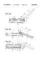
- FIG. 1is an isometric view of a handheld computer organizer which is partially broken-away to depict a hinge arrangement constructed in accordance with a preferred embodiment of the invention.
- FIGS. 2A-2Care side view drawings of the handheld computer organizer depicted in FIG. 1, such drawings illustrating pivot of a cover panel relative to a base panel substantially throughout 360-degrees of rotation.
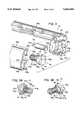
- FIG. 3is an enlarged and exploded isometric view of the preferred embodiment hinge arrangement, such hinge arrangement including first and second hinges which operate in connection with a linkage element.
- FIGS. 3A and 3Bare isometric views of one of the hinges shown in FIG. 3, such hinge being illustrated from differing perspectives.
- FIG. 4is a further enlarged and fragmented isometric view of the computer organizer of FIG. 1, the preferred embodiment hinge arrangement being shown in detail.
- FIG. 1shows, at 10, a handheld computer organizer having a base panel 12 and a cover panel 14.
- base panel 12defines a keyboard 12a, such keyboard being configured in accordance with a standard computer keyboard of the type well known in the art.
- the base panelalso defines a cavity 12b configured to receive a stylus 16 which takes the form generally of a pen.
- Cover panel 14it will be noted, defines a display screen 14a which is configured to accept input from the pen-like stylus, allowing a user to draw images on the display screen.
- FIGS. 2A-2Cillustrate pivot of the cover panel from a fully-closed orientation (FIG. 2A) to a fully-open orientation (FIG. 2C), various intermediate orientations being shown in dashed lines. This is achieved via a hinge arrangement 18 which pivotally couples the base and cover panels in a manner which will now be described.
- hinge arrangement 18includes a linkage element 20 which connects the base and covey panels via a pair of hinges so as to enable opening and closing of the device.
- a first hinge 30pivotally connects the linkage element to the .cover panel to define a first hinge axis A.
- a second hinge 40pivotally connects the linkage element to the base panel to define a second hinge axis B.
- the two hinge axesare spaced from one another in order to accommodate pivot of the cover panel relative to the base panel substantially throughout 360-degrees of rotation.
- cover panel 14pivots relative to base panel 12 using both the first and second hinges, but that the first hinge operates only during a first range of motion of the cover panel and the second hinge operates only during a second range of motion of the cover panel.
- the second range of motiondirectly follows the first range of motion, meaning that at least one of the first and second hinges is restricted at any given time.
- only the first hinge, or the second hingeoperates at any one time.
- first hinge and second hingeare used broadly herein to refer either to a single hinge, or to a series of hinges which define a single hinge axis.
- cover panel 14To open the device, cover panel 14 initially is pivoted about first axis A via first hinge 30, linkage element 20 remaining fixed relative to base panel 12. If the user wishes to use the organizer as a desktop computer, the cover panel is pivoted to the "landscape orientation" shown at 14'. If the user wishes to use the organizer as a note pad, pivot continues through the first range of motion as indicated by arrow 50. Upon reaching a predetermined intermediate open orientation (FIG. 2B), cover panel 14 will engage linkage element 20 so as to oppose further pivot of the cover panel about first axis A. In the depicted embodiment, an exterior cover panel surface 52 engages an exterior linkage element surface, 54, surface 54 acting as a hard stop.
- the other limitis defined at a pivotal angle of 0-degrees where the device is fully-closed. Thereafter, the linkage element and cover panel pivot together about second axis B (as illustrated by arrow 60 in FIG. 2C). The cover panel and linkage element pivot through a second range of motion to the "portrait orientation" where the cover panel is folded back against the base panel. One limit of the second range of motion corresponds to a limit of the first range of motion as shown in FIG. 2C at 14". The other limit is the fully-open orientation where the cover panel engages the base panel as also shown in FIG. 2C. The cover panel thus will be seen to pivot an angle ⁇ 2 relative to the base panel, ⁇ 2 representing pivot substantially throughout 360-degrees of rotation. The device then may be turned over so that the display screen may be used as a note pad.
- first hinge 30is operable during pivot within the first range of motion of the cover panel
- second hinge 40is operable during pivot within the second range of motion of the cover panel. This is achieved by employing hinges with differing torque characteristics, the first hinge being operable upon achieving a first torque T 1 and the second hinge being operable upon achieving a second torque T 2 which is greater than the first torque.
- linkage element 20is a two-piece construction, such pieces coming together to capture first hinge 30 and second hinge 40, and thereby to define a cooperative hinge arrangement whereby fluid opening and closing of the organizer may be achieved.
- the linkage elementincludes a back piece 20a and a front piece 20b, each configured specially for combination with the other.
- the back piecefor example, defines an upper socket portion 22a and a lower socket portion 24a which combine with an upper socket portion 22b and a lower socket portion 24b of the front piece to provide upper and lower hinge sockets.
- the upper hinge socketseats first hinge 30.
- the lower hinge socketseats second hinge 40.
- Each hinge socketis configured to allow pivot of its hinge about a corresponding hinge axis, but the lower hinge socket also defines locking mechanism whereby pivotal operation of the second hinge may be opposed.
- Lower socket portion 24athus will be seen to define a first notch having a floor 26a
- lower socket portion 24bwill be seen to define a second notch having a floor 26b.
- the first notchhas opposite side walls 25a, 27a.
- the second notchsimilarly has opposite side walls 25b, 27b.
- Side walls 27a, 27bare generally perpendicular to respective notch floors.
- Side walls 25a, 25bare at obtuse angles relative to respective notch floors so as to enable cammed engagement with corresponding cammed locking tabs as will be described below.
- first hinge 30such hinge includes a shaft 32 mounted in a housing 34.
- Housing 34includes a frictional bushing (not shown) which opposes pivot of shaft 32 with a substantially constant frictional force.
- Shaft 32thus is rotatable within housing 34 only upon achieving a corresponding first torque T 1 which overcomes the opposition of the frictional bushing.
- shaft 32rotates under a first torque T 1 of approximately 11.2-16.0 Newton-millimeters.
- Shaft 32includes a tab 32a configured for receipt within a slot 14b of cover panel 14 (FIG. 4), effectively fixing shaft 32 relative to cover panel 12.
- Housing 34includes a tab 34a configured for receipt within a corresponding slot 23 of linkage element back piece 20a. This effectively fixes housing 34 relative to linkage element 20.
- First hinge 30thus is operable upon application of a torque T 1 to pivot the cover panel relative to the linkage element through a first range of motion.
- the linkage elementnominally is fixed relative to the base panel until application of a second torque T 2 (greater than first torque T 1 ) which is capable of releasing the locking mechanism of second hinge 40.
- the cover panelnominally pivots relative to the base panel through a first range of motion defined oppositely by the fully-closed orientation (FIG. 2A) and the intermediate open orientation (FIG. 2B).
- Torque T 2typically will not be applied where pivot may be achieved under a first torque T 1 , as during the first range of motion.
- the second hingeincludes a pintle 42 having a tab 42a which seats within a slot 12c of base panel 12 (FIG. 4). This effectively fixes the pintle relative to the base panel.
- Pintle 42also seats within a socket defined by lower socket portions 24a, 24b, but such seat is releasably lockable to provide for pivot of the linkage element relative to the base panel upon application of a second torque T 2 .
- the pintleis mounted in the socket via an annular rib of the linkage element (a portion of which is shown at 28a), such rib being configured to fit within a corresponding annular channel 48 of pintle 42.
- a helical spring 44extends along the pintle between a fixed washer 44a and a related floating washer 44b. Washer 44b defines one wall of annular channel 48. The other wall is defined by the contour of pintle 42. The channel thus may be altered (i.e., widened) upon overcoming the bias of helical spring 44.
- Pintle 42also includes a head 43 from which extends a pair of cammed locking tabs 46a, 46b which matingly fit into corresponding notches of linkage element 20.
- Locking tabs 46a, 46bare shown in detail in FIGS. 3A and 3B which depict the second hinge from differing perspectives. As indicated therein, each locking tab defines a side wall 47a, 47b which is generally perpendicular to the corresponding locking tab's floor-contacting surface, and a side wall 45a, 45b which is at an obtuse angle relative to the corresponding locking tab's floor-contacting surface so as to enable cammed engagement with a corresponding notch side wall.
- Second torque T 2typically is at least twice torque T 1 , and preferably is 30-32 Newton-millimeters.
- This second torquecauses the locking tabs to cammingly disengage the notches, the locking tabs riding up cammed side walls 25a, 25b and onto the exterior surfaces of the lower socket.
- Pintle 42thus is movable laterally as indicated at 70 in FIG. 4. Thereafter, the locking tabs ride along the exterior surfaces, the primary opposition to such rotation coming from frictional forces therebetween. The pintle then rotates under a torque T 3 which is less than both T 2 and T 1 .
- the first hingethus operates upon application of a first torque to the cover panel pivot the cover panel through a first range of motion, beyond which the first hinge is opposed by a relatively high restrictive force.
- the second hingeoperates upon similar application of a second torque which is greater than the first torque, but insufficient to overcome the restrictive force.
- the cover panelpivots through a second range of motion, the second range of motion typically following the first range of motion.
- the second hingeis fixed during operation of the first hinge, and the first hinge is fixed during operation of the second hinge.
- the linkage elementis fixed relative to the base panel during operation of the first hinge and is fixed relative to the cover panel during operation of the second hinge. This enables controlled pivot of the first panel relative to the second panel substantially throughout 360-degrees of rotation without requiting manual adjustment of the linkage element.
- the invented hinge arrangementthus will be seen to greatly improve opening and dosing of a clamshell-like device such as a handheld computer organizer.
- To open the deviceit is necessary only to pivot the cover panel relative to the base panel, the required torques to pivot the hinges during different phases of rotation be selected-to automatically handoff hinge operation from one hinge to another in accordance with predetermined criteria.
- a first hingewill operate under a torque T 1 during a first range of motion of the cover panel, beyond which an opposing force in the form of a hard stop will be encountered.
- a second hingewill operate upon application of a second torque T 2 .
- the second hingewill operate under a third torque T 3 through the second range of motion.
Landscapes
- Engineering & Computer Science (AREA)
- Computer Hardware Design (AREA)
- Theoretical Computer Science (AREA)
- Physics & Mathematics (AREA)
- Human Computer Interaction (AREA)
- General Engineering & Computer Science (AREA)
- General Physics & Mathematics (AREA)
- Mathematical Physics (AREA)
- Signal Processing (AREA)
- Pivots And Pivotal Connections (AREA)
- Casings For Electric Apparatus (AREA)
Abstract
Description
Claims (16)
Priority Applications (4)
| Application Number | Priority Date | Filing Date | Title |
|---|---|---|---|
| US08/535,724US5666694A (en) | 1995-09-28 | 1995-09-28 | Hinge arrangement |
| DE19618325ADE19618325C2 (en) | 1995-09-28 | 1996-05-07 | Hinge arrangement |
| GB9617345AGB2305689B (en) | 1995-09-28 | 1996-08-19 | Hinge arrangement |
| JP25566296AJP3718298B2 (en) | 1995-09-28 | 1996-09-27 | Hinge device |
Applications Claiming Priority (1)
| Application Number | Priority Date | Filing Date | Title |
|---|---|---|---|
| US08/535,724US5666694A (en) | 1995-09-28 | 1995-09-28 | Hinge arrangement |
Publications (1)
| Publication Number | Publication Date |
|---|---|
| US5666694Atrue US5666694A (en) | 1997-09-16 |
Family
ID=24135503
Family Applications (1)
| Application Number | Title | Priority Date | Filing Date |
|---|---|---|---|
| US08/535,724Expired - LifetimeUS5666694A (en) | 1995-09-28 | 1995-09-28 | Hinge arrangement |
Country Status (4)
| Country | Link |
|---|---|
| US (1) | US5666694A (en) |
| JP (1) | JP3718298B2 (en) |
| DE (1) | DE19618325C2 (en) |
| GB (1) | GB2305689B (en) |
Cited By (103)
| Publication number | Priority date | Publication date | Assignee | Title |
|---|---|---|---|---|
| US5947440A (en)* | 1996-11-06 | 1999-09-07 | Samsung Electronics Co., Ltd. | Flat-panel display apparatus |
| US6032918A (en)* | 1996-11-03 | 2000-03-07 | Samsung Electronics Co., Ltd. | Multi-functional device for a display device |
| US6125040A (en)* | 1998-02-27 | 2000-09-26 | Fujitsu Limited | Information processing apparatus and hook mechanism applicable to the apparatus |
| US6154359A (en)* | 1996-12-02 | 2000-11-28 | Fujitsu Limited | Portable information processing apparatus |
| US6185096B1 (en)* | 1997-10-31 | 2001-02-06 | Hewlett-Packard Company | Adjustable height docking station and computing device for use therewith |
| US6249951B1 (en)* | 1997-05-30 | 2001-06-26 | Nec Corporation | Hinge structure for electronic apparatus |
| US6268997B1 (en) | 1996-11-06 | 2001-07-31 | Samsung Electronics Co., Ltd. | Flat-panel display apparatus having stand unit with cable passing through hinge shaft |
| US6338182B1 (en)* | 2000-01-28 | 2002-01-15 | Hon Hai Precision Ind. Co., Ltd. | Hinge assembly |
| US20020167789A1 (en)* | 2001-05-11 | 2002-11-14 | Cema Technologies, Inc. | Hinge assembly for rotatably mounting a display to a surface |
| US20020173340A1 (en)* | 2001-05-15 | 2002-11-21 | Alps Electric Co., Ltd. | Input device connected to mobile communication terminal with which characters can be input easily |
| US6492974B1 (en) | 1996-10-08 | 2002-12-10 | Fujitsu Limited | Small-sized portable information processing apparatus |
| US6539580B2 (en)* | 2001-04-20 | 2003-04-01 | Hewlett-Packard Company | Hinge assembly for a cover |
| US20030073456A1 (en)* | 2001-10-16 | 2003-04-17 | Griffin Jason T. | Handheld mobile communication device |
| US20030086241A1 (en)* | 2001-11-08 | 2003-05-08 | Wistron Corporation | Positioning unit for an electronic device |
| US20030124992A1 (en)* | 1996-10-28 | 2003-07-03 | Therefore Limited | Hand-held computer and communications apparatus |
| US20030156095A1 (en)* | 2001-03-22 | 2003-08-21 | Kazuyoshi Yano | Display unit |
| US6628506B2 (en) | 2001-07-24 | 2003-09-30 | Hewlett-Packard Development Company, L.P. | Multifunctional foldable computer |
| EP0943979A3 (en)* | 1998-03-16 | 2003-10-22 | Fujitsu Limited | Imformation processing device |
| US6676098B2 (en)* | 2002-04-18 | 2004-01-13 | Quanta Computer, Inc. | Plane display with a foldable support |
| US20040020012A1 (en)* | 2002-08-02 | 2004-02-05 | Gupte Sheel A. | Self-contained hinge for flip-style device |
| US6697495B1 (en)* | 1998-12-01 | 2004-02-24 | Samsung Electronics Co., Ltd. | Portable computer speaker assembly |
| US6697055B1 (en)* | 1995-11-16 | 2004-02-24 | Edward Bullister | Multifunctional portable computing device with special housing |
| US20040085738A1 (en)* | 2002-11-06 | 2004-05-06 | Walkabout Computers, Inc. | Secure hinge mechanism for portable computer |
| US6757157B2 (en)* | 2001-04-02 | 2004-06-29 | Nokia Corporation | Folding electronic device |
| US20040155861A1 (en)* | 2002-05-30 | 2004-08-12 | Jackson Iii Robert P. | Portable display monitor |
| US6798649B1 (en) | 2002-02-25 | 2004-09-28 | Think Outside, Inc. | Mobile computer with foldable keyboard |
| US20040198245A1 (en)* | 2002-09-17 | 2004-10-07 | Chow Tatt Hoong | Latch mechanism and electronic device employing a latch mechanism |
| US6873521B2 (en)* | 2001-07-24 | 2005-03-29 | Hewlett-Packard Development Company, L.P. | Multiple environment foldable computer |
| US6888534B1 (en)* | 2001-01-30 | 2005-05-03 | Palmone, Inc. | Segmented keyboard for portable computer system |
| US6912121B2 (en)* | 2002-01-28 | 2005-06-28 | International Business Machines Corporation | Personal computer device having constant tilt display with adjustable height |
| US20050155184A1 (en)* | 2004-01-16 | 2005-07-21 | Kayl Paul R. | Mobile computer hinge assembly |
| US20050155182A1 (en)* | 2004-01-20 | 2005-07-21 | Young-Soo Han | Hinge device |
| US20050220294A1 (en)* | 2004-02-02 | 2005-10-06 | Amphenol-T&M Antennas | Push-button hinge for handheld devices |
| FR2868892A1 (en)* | 2004-04-09 | 2005-10-14 | Phoenix Korea Co Ltd | PORTABLE DEVICE COMPRISING TWO ROTATING AND FOLDING UNITS AND HINGE DEVICE USED FOR SUCH A DEVICE |
| US20050239520A1 (en)* | 2004-04-21 | 2005-10-27 | Stefansen Mads S | Hinge for fold phone |
| US20050250355A1 (en)* | 2004-05-05 | 2005-11-10 | Asutek Computer Inc. | Hinge structure and electronic apparatus |
| US20060034601A1 (en)* | 2003-04-23 | 2006-02-16 | Tage Andersson | Multi-function two panel electronic device with 360° relative motion |
| US20060179612A1 (en)* | 2003-04-03 | 2006-08-17 | Kazuyoshi Oshima | Device case opening/closing device, and 2-axis hinge device |
| US20060193469A1 (en)* | 2004-06-08 | 2006-08-31 | Tony Kfoury | Parallel plane rotation hinge for a portable device |
| US20060236505A1 (en)* | 2003-04-23 | 2006-10-26 | Maatta Esa S | Mobile communications device with synchronising hinge |
| US20060238968A1 (en)* | 2003-04-23 | 2006-10-26 | Esa-Sakari Maatta | Mobile communications device with synchronising hinge |
| US20060238970A1 (en)* | 2005-04-21 | 2006-10-26 | Mikko Ukonaho | Mobile communications device with synchronising hinge |
| CN1303492C (en)* | 2003-12-10 | 2007-03-07 | 三星电子株式会社 | Portable computer |
| US20070151381A1 (en)* | 2005-12-20 | 2007-07-05 | Nokia Corporation | Foldable electronic device having double-axis hinge and locking spring |
| US20080109992A1 (en)* | 2006-11-13 | 2008-05-15 | Shin Zu Shing Co., Ltd. | Hinge with less abrasion |
| US7373692B2 (en) | 2004-06-08 | 2008-05-20 | Amphenol-T&M Antennas | Parallel plane rotation hinge for a portable device |
| US20090096209A1 (en)* | 2007-10-10 | 2009-04-16 | Transdigm, Inc., | Flexible, self-bonding coupling assembly |
| DE102008013560A1 (en)* | 2008-03-28 | 2009-09-17 | E-LEAD ELECTRONIC CO., LTD., Shengang Shiang | Tandem axle structure for e.g. tablet-personal computer, has camshaft made for rotation center of retractable movement to open structure so that disk, blocking bodies and spring are fitted back and back and operation of computer is enabled |
| US20100071155A1 (en)* | 2005-08-02 | 2010-03-25 | Sanyo Electric Co., Ltd. | Foldable device |
| US20100110625A1 (en)* | 2008-10-31 | 2010-05-06 | Asustek Computer Inc. | Foldable mobile computing device and operating method of the same |
| US20100149764A1 (en)* | 2005-07-28 | 2010-06-17 | Sanyo Electric Co., Ltd. | Hinge mechanism of foldable device, and foldable device provided with hinge mechanism |
| US20110147398A1 (en)* | 2010-05-06 | 2011-06-23 | Clamcase, Llc | Electronic device case and method of use |
| US20110199727A1 (en)* | 2010-01-28 | 2011-08-18 | Brian Probst | Tablet computer case and associated methods |
| US8467185B2 (en) | 2010-01-28 | 2013-06-18 | Cruxcase, Llc | Tablet computer case and associated methods |
| US8467179B2 (en) | 2010-01-28 | 2013-06-18 | Cruxcase, Llc | Tablet computer case and associated methods |
| US20130220856A1 (en)* | 2010-11-11 | 2013-08-29 | Koninklijke Philips Electronics N.V. | Carrying case for defibrillator and accessories |
| US20140043749A1 (en)* | 2012-08-13 | 2014-02-13 | Wistron Corporation | Portable computer |
| US8687354B2 (en) | 2012-01-30 | 2014-04-01 | Lenovo (Singapore) Pte. Ltd. | Dual shaft hinge with angle timing shaft mechanism |
| US20140185233A1 (en)* | 2012-12-28 | 2014-07-03 | Mark MacDonald | Hinge assembly for electronic device |
| US20140251045A1 (en)* | 2013-03-11 | 2014-09-11 | First Dome Corporation | Synchronous movement device applied to dual-shaft system |
| US20140347805A1 (en)* | 2013-05-21 | 2014-11-27 | Inventec Corporation | Portable electronic device |
| US8904601B2 (en)* | 2013-03-11 | 2014-12-09 | First Dome Corporation | Synchronous movement device applied to dual-shaft system |
| US20150040704A1 (en)* | 2013-06-11 | 2015-02-12 | First Dome Corporation | Synchronous movement device applied to dual-shaft system |
| US20150160695A1 (en)* | 2013-12-06 | 2015-06-11 | Yuan Deng Metals Industrial Co., Ltd. | Hinge unit with simultaneous rotatable axles |
| US20150173218A1 (en)* | 2013-12-17 | 2015-06-18 | First Dome Corporation | Parallelism fixing device applied to dual-shaft system |
| US20150189777A1 (en)* | 2013-12-31 | 2015-07-02 | First Dome Corporation | Transmission stabilization device applied to dual-shaft system |
| US9128664B1 (en)* | 2012-01-18 | 2015-09-08 | Google Inc. | Invertible clamshell notebook computer |
| US20150301564A1 (en)* | 2014-04-16 | 2015-10-22 | Quanta Computer Inc. | Laptop computer |
| USD742871S1 (en) | 2014-06-05 | 2015-11-10 | Incipio Technologies, Inc. | Computer case |
| US9265166B2 (en)* | 2014-02-25 | 2016-02-16 | First Dome Corporation | Parallelism control device applied to dual-shaft system |
| US9290976B1 (en)* | 2014-10-22 | 2016-03-22 | Chin-Hsing Horng | Position-limit hinge |
| USD755781S1 (en) | 2014-06-05 | 2016-05-10 | Incipio, Llc | Computer case |
| US9447620B2 (en) | 2014-09-30 | 2016-09-20 | Microsoft Technology Licensing, Llc | Hinge mechanism with multiple preset positions |
| CN105988515A (en)* | 2015-02-12 | 2016-10-05 | 宏碁股份有限公司 | Pivoting mechanism and portable electronic device |
| US9487981B1 (en)* | 2015-06-26 | 2016-11-08 | Intel Corporation | Cylindrical dual axis hinge for electronic devices |
| US9489054B1 (en) | 2016-01-05 | 2016-11-08 | Zagg Intellectual Property Holding Co., Inc. | Keyboard folio with attachment strip |
| US9557776B1 (en) | 2016-05-10 | 2017-01-31 | Zagg Intellectual Property Holding Co., Inc. | Friction resistance hinge with auto-lock |
| US9752361B2 (en)* | 2015-06-18 | 2017-09-05 | Microsoft Technology Licensing, Llc | Multistage hinge |
| TWI603180B (en)* | 2011-12-28 | 2017-10-21 | 英特爾股份有限公司 | Electronic device and housing for electronic device |
| US9933814B2 (en) | 2014-06-27 | 2018-04-03 | Hewlett-Packard Development Company, L.P. | Computing device with a rotable display member |
| US20180164855A1 (en)* | 2016-12-09 | 2018-06-14 | Microsoft Technology Licensing, Llc | Computing device employing a self-spacing hinge assembly |
| US10024092B1 (en)* | 2014-03-26 | 2018-07-17 | Google Llc | 360 degree dual pivot variable torque hinge mechanism |
| US10037057B2 (en) | 2016-09-22 | 2018-07-31 | Microsoft Technology Licensing, Llc | Friction hinge |
| US10146268B2 (en) | 2016-08-11 | 2018-12-04 | Microsoft Technology Licensing, Llc | Hinge apparatus, systems, and methods |
| US10227808B2 (en) | 2015-11-20 | 2019-03-12 | Microsoft Technology Licensing, Llc | Hinged device |
| US10253804B2 (en) | 2017-01-24 | 2019-04-09 | Microsoft Technology Licensing, Llc | Hinged device |
| US10296044B2 (en) | 2017-06-08 | 2019-05-21 | Microsoft Technology Licensing, Llc | Hinged device |
| US20190163240A1 (en)* | 2017-11-29 | 2019-05-30 | Compal Electronics, Inc. | Foldable electronic device |
| US10310564B2 (en)* | 2014-06-30 | 2019-06-04 | Hewlett-Packard Development Company, L.P. | Linking mechanism for a computing device with a rotatable display member |
| US10317951B2 (en) | 2015-11-12 | 2019-06-11 | Hewlett-Packard Development Company, L.P. | Hinge mechanism for a computing device |
| US10344510B2 (en) | 2017-06-16 | 2019-07-09 | Microsoft Technology Licensing, Llc | Hinged device |
| US10364598B2 (en) | 2016-09-02 | 2019-07-30 | Microsoft Technology Licensing, Llc | Hinged device |
| WO2019196317A1 (en)* | 2018-04-11 | 2019-10-17 | 华为技术有限公司 | Hinge structure, hinge device, and electronic device |
| TWI676093B (en)* | 2016-05-19 | 2019-11-01 | 仁寶電腦工業股份有限公司 | Pivot structure assembly and electronic device |
| US10474203B2 (en) | 2016-09-01 | 2019-11-12 | Microsoft Technology Licensing, Llc | Hinged device |
| US10641318B2 (en) | 2016-12-09 | 2020-05-05 | Microsoft Technology Licensing, Llc | Hinged device |
| US10677387B2 (en)* | 2018-10-23 | 2020-06-09 | Samsung Electronics Co., Ltd. | Electronic device including stand member |
| US20200270022A1 (en)* | 2017-10-13 | 2020-08-27 | Kyoraku Co., Ltd. | Container, folding container |
| US11066861B2 (en) | 2016-12-19 | 2021-07-20 | Huawei Technologies Co., Ltd. | Notebook computer |
| US20220100238A1 (en)* | 2020-09-29 | 2022-03-31 | Microsoft Technology Licensing, Llc | Hinge assembly for mobile computing device |
| US11669132B2 (en) | 2020-09-29 | 2023-06-06 | Microsoft Technology Licensing, Llc | Hinge assembly for mobile computing device |
| US11720151B2 (en) | 2020-08-03 | 2023-08-08 | Microsoft Technology Licensing, Llc | Hinged device |
| US20250117050A1 (en)* | 2023-10-04 | 2025-04-10 | Dell Products L.P. | Modular portable information handling system hinge with selectively disengaged rotation stop |
Families Citing this family (20)
| Publication number | Priority date | Publication date | Assignee | Title |
|---|---|---|---|---|
| US6838810B1 (en) | 1997-03-21 | 2005-01-04 | Chunghwa Picture Tubes, Ltd. | Flat-panel display mounting system for portable computer |
| US6002457A (en)* | 1997-04-08 | 1999-12-14 | Lg Lcd, Inc. | Computer having liquid crystal display |
| JP3296993B2 (en)* | 1997-04-08 | 2002-07-02 | エルジー フィリップス エルシーディー カンパニー リミテッド | Portable computer with liquid crystal display |
| KR100218581B1 (en) | 1997-04-08 | 1999-09-01 | 구자홍 | Portable computer with LCD |
| KR100256971B1 (en)* | 1997-05-24 | 2000-05-15 | 구본준 | Lcd module fixing device for notebook computers |
| US7492421B1 (en) | 1997-07-03 | 2009-02-17 | Lg Display Co., Ltd. | Case for liquid crystal display |
| KR100248856B1 (en)* | 1997-09-04 | 2000-03-15 | 구본준 | LCD Display |
| US6501641B1 (en) | 1998-10-23 | 2002-12-31 | Lg. Philips Lcd Co. Ltd. | Portable computer having a flat panel display device |
| KR100508003B1 (en) | 1998-11-11 | 2005-11-21 | 엘지.필립스 엘시디 주식회사 | How to combine a portable computer with its flat panel display |
| DE19950006C2 (en)* | 1999-10-18 | 2001-11-29 | Rfi Mobile Technologies Ag | System consisting of a portable computer and a connection station |
| JP4265948B2 (en)* | 2003-09-08 | 2009-05-20 | スガツネ工業株式会社 | Biaxial hinge device and portable device |
| JP4241241B2 (en)* | 2003-07-10 | 2009-03-18 | カシオ計算機株式会社 | Hinge structure and electronic equipment |
| JP5170950B2 (en)* | 2005-01-25 | 2013-03-27 | 三洋電機株式会社 | Hinge device |
| JP4326510B2 (en)* | 2005-08-02 | 2009-09-09 | 三洋電機株式会社 | Folding equipment |
| JP2007107592A (en)* | 2005-10-12 | 2007-04-26 | Strawberry Corporation | Hinge device and electronic apparatus using hinge device |
| DE112006003709B4 (en) | 2006-03-09 | 2013-02-14 | Mitsubishi Electric Corp. | Monitor opening and closing mechanism |
| JP5112121B2 (en)* | 2008-03-13 | 2013-01-09 | 加藤電機株式会社 | Biaxial hinge device and electronic equipment |
| JP4891982B2 (en)* | 2008-12-15 | 2012-03-07 | スガツネ工業株式会社 | Biaxial hinge device and portable device |
| JP5704613B2 (en)* | 2012-05-30 | 2015-04-22 | 株式会社ナチュラレーザ・ワン | 2-axis hinge |
| CN104314968B (en)* | 2014-10-14 | 2017-01-11 | 合肥联宝信息技术有限公司 | Rotating shaft structure for notebook computer |
Citations (16)
| Publication number | Priority date | Publication date | Assignee | Title |
|---|---|---|---|---|
| AT111818B (en)* | 1927-10-14 | 1928-12-27 | Masch Kisten U Holzwaren Fabr | Three-part hinge. |
| GB2033956A (en)* | 1978-10-04 | 1980-05-29 | Chereau J | Hinge |
| US4330219A (en)* | 1979-08-04 | 1982-05-18 | Hitachi Koki Company, Limited | Upper cover for line printer |
| US4615464A (en)* | 1983-12-21 | 1986-10-07 | Custom-Pak, Incorporated | Molded container case with hinge and method for making same |
| US4825395A (en)* | 1986-05-29 | 1989-04-25 | Hewlett-Packard Company | Apparatus with torsionally stressed conductors routed through a hollow articulated hinge |
| US4846536A (en)* | 1986-06-30 | 1989-07-11 | Kabushiki Kaisha Toshiba | Portable apparatus |
| US4928350A (en)* | 1988-04-07 | 1990-05-29 | Morgan James C | Multiple axis hidden hinge |
| US4960256A (en)* | 1988-08-08 | 1990-10-02 | Sony Corporation | Holding structure for displaying apparatus |
| US4976007A (en)* | 1989-06-22 | 1990-12-11 | Quanta Computer Inc. | Connecting device for portable computers |
| WO1993001700A1 (en)* | 1991-07-11 | 1993-01-21 | Zeos International, Ltd. | Pivot and swivel mechanism for lap top display |
| EP0550909A1 (en)* | 1992-01-09 | 1993-07-14 | Microsoft Corporation | Adjustable stand for pointing device |
| US5231734A (en)* | 1991-11-04 | 1993-08-03 | General Clutch Corporation | Friction hinge assembly |
| US5278725A (en)* | 1991-04-12 | 1994-01-11 | Matsushita Electric Industrial Co., Ltd. | Foldable electronic apparatus having a hollow hinge assembly through which a flexible cable is routed |
| US5282293A (en)* | 1992-06-01 | 1994-02-01 | At&T Bell Laboratories | 180° concealed hinge |
| WO1995000406A1 (en)* | 1993-06-21 | 1995-01-05 | Motorola Inc. | Friction clutch for dual pivot point hinge |
| US5555157A (en)* | 1994-03-02 | 1996-09-10 | Apple Computer, Inc. | Enclosure for electronic apparatus having a cover catch member engageable with two different housing catch members |
Family Cites Families (1)
| Publication number | Priority date | Publication date | Assignee | Title |
|---|---|---|---|---|
| US5976007A (en)* | 1998-02-27 | 1999-11-02 | Powell; Robert A. | Security vent |
- 1995
- 1995-09-28USUS08/535,724patent/US5666694A/ennot_activeExpired - Lifetime
- 1996
- 1996-05-07DEDE19618325Apatent/DE19618325C2/ennot_activeExpired - Fee Related
- 1996-08-19GBGB9617345Apatent/GB2305689B/ennot_activeExpired - Lifetime
- 1996-09-27JPJP25566296Apatent/JP3718298B2/ennot_activeExpired - Fee Related
Patent Citations (16)
| Publication number | Priority date | Publication date | Assignee | Title |
|---|---|---|---|---|
| AT111818B (en)* | 1927-10-14 | 1928-12-27 | Masch Kisten U Holzwaren Fabr | Three-part hinge. |
| GB2033956A (en)* | 1978-10-04 | 1980-05-29 | Chereau J | Hinge |
| US4330219A (en)* | 1979-08-04 | 1982-05-18 | Hitachi Koki Company, Limited | Upper cover for line printer |
| US4615464A (en)* | 1983-12-21 | 1986-10-07 | Custom-Pak, Incorporated | Molded container case with hinge and method for making same |
| US4825395A (en)* | 1986-05-29 | 1989-04-25 | Hewlett-Packard Company | Apparatus with torsionally stressed conductors routed through a hollow articulated hinge |
| US4846536A (en)* | 1986-06-30 | 1989-07-11 | Kabushiki Kaisha Toshiba | Portable apparatus |
| US4928350A (en)* | 1988-04-07 | 1990-05-29 | Morgan James C | Multiple axis hidden hinge |
| US4960256A (en)* | 1988-08-08 | 1990-10-02 | Sony Corporation | Holding structure for displaying apparatus |
| US4976007A (en)* | 1989-06-22 | 1990-12-11 | Quanta Computer Inc. | Connecting device for portable computers |
| US5278725A (en)* | 1991-04-12 | 1994-01-11 | Matsushita Electric Industrial Co., Ltd. | Foldable electronic apparatus having a hollow hinge assembly through which a flexible cable is routed |
| WO1993001700A1 (en)* | 1991-07-11 | 1993-01-21 | Zeos International, Ltd. | Pivot and swivel mechanism for lap top display |
| US5231734A (en)* | 1991-11-04 | 1993-08-03 | General Clutch Corporation | Friction hinge assembly |
| EP0550909A1 (en)* | 1992-01-09 | 1993-07-14 | Microsoft Corporation | Adjustable stand for pointing device |
| US5282293A (en)* | 1992-06-01 | 1994-02-01 | At&T Bell Laboratories | 180° concealed hinge |
| WO1995000406A1 (en)* | 1993-06-21 | 1995-01-05 | Motorola Inc. | Friction clutch for dual pivot point hinge |
| US5555157A (en)* | 1994-03-02 | 1996-09-10 | Apple Computer, Inc. | Enclosure for electronic apparatus having a cover catch member engageable with two different housing catch members |
Cited By (156)
| Publication number | Priority date | Publication date | Assignee | Title |
|---|---|---|---|---|
| US6697055B1 (en)* | 1995-11-16 | 2004-02-24 | Edward Bullister | Multifunctional portable computing device with special housing |
| US6492974B1 (en) | 1996-10-08 | 2002-12-10 | Fujitsu Limited | Small-sized portable information processing apparatus |
| US20030124992A1 (en)* | 1996-10-28 | 2003-07-03 | Therefore Limited | Hand-held computer and communications apparatus |
| US6032918A (en)* | 1996-11-03 | 2000-03-07 | Samsung Electronics Co., Ltd. | Multi-functional device for a display device |
| US5947440A (en)* | 1996-11-06 | 1999-09-07 | Samsung Electronics Co., Ltd. | Flat-panel display apparatus |
| US6268997B1 (en) | 1996-11-06 | 2001-07-31 | Samsung Electronics Co., Ltd. | Flat-panel display apparatus having stand unit with cable passing through hinge shaft |
| US6154359A (en)* | 1996-12-02 | 2000-11-28 | Fujitsu Limited | Portable information processing apparatus |
| US6249951B1 (en)* | 1997-05-30 | 2001-06-26 | Nec Corporation | Hinge structure for electronic apparatus |
| US6185096B1 (en)* | 1997-10-31 | 2001-02-06 | Hewlett-Packard Company | Adjustable height docking station and computing device for use therewith |
| US6125040A (en)* | 1998-02-27 | 2000-09-26 | Fujitsu Limited | Information processing apparatus and hook mechanism applicable to the apparatus |
| EP0943979A3 (en)* | 1998-03-16 | 2003-10-22 | Fujitsu Limited | Imformation processing device |
| US6697495B1 (en)* | 1998-12-01 | 2004-02-24 | Samsung Electronics Co., Ltd. | Portable computer speaker assembly |
| US6338182B1 (en)* | 2000-01-28 | 2002-01-15 | Hon Hai Precision Ind. Co., Ltd. | Hinge assembly |
| US6888534B1 (en)* | 2001-01-30 | 2005-05-03 | Palmone, Inc. | Segmented keyboard for portable computer system |
| US20030156095A1 (en)* | 2001-03-22 | 2003-08-21 | Kazuyoshi Yano | Display unit |
| US7057886B2 (en)* | 2001-03-22 | 2006-06-06 | Sony Corporation | Display unit |
| EP1372129A4 (en)* | 2001-03-22 | 2008-04-30 | Sony Corp | Display unit |
| US6757157B2 (en)* | 2001-04-02 | 2004-06-29 | Nokia Corporation | Folding electronic device |
| US6539580B2 (en)* | 2001-04-20 | 2003-04-01 | Hewlett-Packard Company | Hinge assembly for a cover |
| US20020167789A1 (en)* | 2001-05-11 | 2002-11-14 | Cema Technologies, Inc. | Hinge assembly for rotatably mounting a display to a surface |
| US6871384B2 (en) | 2001-05-11 | 2005-03-29 | Cema Technologies, Inc. | Hinge assembly for rotatably mounting a display to a surface |
| US7107083B2 (en)* | 2001-05-15 | 2006-09-12 | Alps Electric Co., Ltd. | Input device connected to mobile communication terminal with which characters can be input easily |
| US20020173340A1 (en)* | 2001-05-15 | 2002-11-21 | Alps Electric Co., Ltd. | Input device connected to mobile communication terminal with which characters can be input easily |
| US6628506B2 (en) | 2001-07-24 | 2003-09-30 | Hewlett-Packard Development Company, L.P. | Multifunctional foldable computer |
| US6654234B2 (en) | 2001-07-24 | 2003-11-25 | Hewlett-Packard Development Company, L.P. | Multifunctional foldable computer |
| US6873521B2 (en)* | 2001-07-24 | 2005-03-29 | Hewlett-Packard Development Company, L.P. | Multiple environment foldable computer |
| US8107996B2 (en)* | 2001-10-16 | 2012-01-31 | Research In Motion Limited | Handheld mobile communication device |
| US7881743B2 (en)* | 2001-10-16 | 2011-02-01 | Research In Motion Limited | Handheld mobile communication device |
| US20030073456A1 (en)* | 2001-10-16 | 2003-04-17 | Griffin Jason T. | Handheld mobile communication device |
| US20110092256A1 (en)* | 2001-10-16 | 2011-04-21 | Research In Motion Limited | Handheld mobile communication device |
| USRE40055E1 (en) | 2001-11-08 | 2008-02-12 | Wistron Corporation | Positioning unit for an electronic device |
| US20030086241A1 (en)* | 2001-11-08 | 2003-05-08 | Wistron Corporation | Positioning unit for an electronic device |
| US6654233B2 (en)* | 2001-11-08 | 2003-11-25 | Wistron Corporation | Positioning unit for an electronic device |
| US6912121B2 (en)* | 2002-01-28 | 2005-06-28 | International Business Machines Corporation | Personal computer device having constant tilt display with adjustable height |
| US6798649B1 (en) | 2002-02-25 | 2004-09-28 | Think Outside, Inc. | Mobile computer with foldable keyboard |
| US6676098B2 (en)* | 2002-04-18 | 2004-01-13 | Quanta Computer, Inc. | Plane display with a foldable support |
| US20040155861A1 (en)* | 2002-05-30 | 2004-08-12 | Jackson Iii Robert P. | Portable display monitor |
| US20040020012A1 (en)* | 2002-08-02 | 2004-02-05 | Gupte Sheel A. | Self-contained hinge for flip-style device |
| US7003333B2 (en)* | 2002-09-17 | 2006-02-21 | Motorola, Inc. | Latch mechanism and electronic device employing a latch mechanism |
| US20040198245A1 (en)* | 2002-09-17 | 2004-10-07 | Chow Tatt Hoong | Latch mechanism and electronic device employing a latch mechanism |
| US20040085738A1 (en)* | 2002-11-06 | 2004-05-06 | Walkabout Computers, Inc. | Secure hinge mechanism for portable computer |
| US6741472B1 (en) | 2002-11-06 | 2004-05-25 | Walkabout Computers, Inc. | Secure hinge mechanism for portable computer |
| US7484271B2 (en) | 2003-04-03 | 2009-02-03 | Sugatsune Kogyo Co., Ltd. | Device case opening/closing device, and 2-axis hinge device |
| US20060179612A1 (en)* | 2003-04-03 | 2006-08-17 | Kazuyoshi Oshima | Device case opening/closing device, and 2-axis hinge device |
| US20060238968A1 (en)* | 2003-04-23 | 2006-10-26 | Esa-Sakari Maatta | Mobile communications device with synchronising hinge |
| US20060236505A1 (en)* | 2003-04-23 | 2006-10-26 | Maatta Esa S | Mobile communications device with synchronising hinge |
| US7512426B2 (en) | 2003-04-23 | 2009-03-31 | Nokia Corporation | Mobile communications device with synchronising hinge |
| US7426406B2 (en) | 2003-04-23 | 2008-09-16 | Nokia Corporation | Mobile communications device with synchronising hinge |
| US20060034601A1 (en)* | 2003-04-23 | 2006-02-16 | Tage Andersson | Multi-function two panel electronic device with 360° relative motion |
| CN1303492C (en)* | 2003-12-10 | 2007-03-07 | 三星电子株式会社 | Portable computer |
| US20050155184A1 (en)* | 2004-01-16 | 2005-07-21 | Kayl Paul R. | Mobile computer hinge assembly |
| US20050155182A1 (en)* | 2004-01-20 | 2005-07-21 | Young-Soo Han | Hinge device |
| US7140074B2 (en) | 2004-01-20 | 2006-11-28 | Phoenix Korea Co., Ltd. | Hand-held electronic device including hinge device |
| US20050220294A1 (en)* | 2004-02-02 | 2005-10-06 | Amphenol-T&M Antennas | Push-button hinge for handheld devices |
| FR2868892A1 (en)* | 2004-04-09 | 2005-10-14 | Phoenix Korea Co Ltd | PORTABLE DEVICE COMPRISING TWO ROTATING AND FOLDING UNITS AND HINGE DEVICE USED FOR SUCH A DEVICE |
| US20050239520A1 (en)* | 2004-04-21 | 2005-10-27 | Stefansen Mads S | Hinge for fold phone |
| US7155266B2 (en)* | 2004-04-21 | 2006-12-26 | Nokia Corporation | Hinge for fold phone |
| US20070164924A1 (en)* | 2004-04-21 | 2007-07-19 | Nokia Corporation | Multi-function two pannel device with 360 relative motion |
| US20050250355A1 (en)* | 2004-05-05 | 2005-11-10 | Asutek Computer Inc. | Hinge structure and electronic apparatus |
| US7373692B2 (en) | 2004-06-08 | 2008-05-20 | Amphenol-T&M Antennas | Parallel plane rotation hinge for a portable device |
| US20060193469A1 (en)* | 2004-06-08 | 2006-08-31 | Tony Kfoury | Parallel plane rotation hinge for a portable device |
| US20060238970A1 (en)* | 2005-04-21 | 2006-10-26 | Mikko Ukonaho | Mobile communications device with synchronising hinge |
| US7414834B2 (en) | 2005-04-21 | 2008-08-19 | Nokia Corporation | Mobile communications device with synchronising hinge |
| US20100149764A1 (en)* | 2005-07-28 | 2010-06-17 | Sanyo Electric Co., Ltd. | Hinge mechanism of foldable device, and foldable device provided with hinge mechanism |
| US7907415B2 (en) | 2005-07-28 | 2011-03-15 | Sanyo Electric Co., Ltd. | Hinge mechanism of foldable device, and foldable device provided with hinge mechanism |
| US7930803B2 (en) | 2005-08-02 | 2011-04-26 | Sanyo Electric Co., Ltd. | Foldable device |
| US20100071155A1 (en)* | 2005-08-02 | 2010-03-25 | Sanyo Electric Co., Ltd. | Foldable device |
| US20070151381A1 (en)* | 2005-12-20 | 2007-07-05 | Nokia Corporation | Foldable electronic device having double-axis hinge and locking spring |
| US7667959B2 (en)* | 2005-12-20 | 2010-02-23 | Nokia Corp. | Foldable electronic device having double-axis hinge and locking spring |
| US20080109992A1 (en)* | 2006-11-13 | 2008-05-15 | Shin Zu Shing Co., Ltd. | Hinge with less abrasion |
| US7555817B2 (en)* | 2006-11-13 | 2009-07-07 | Shin Zu Shing Co., Ltd. | Hinge with less abrasion |
| US20090096209A1 (en)* | 2007-10-10 | 2009-04-16 | Transdigm, Inc., | Flexible, self-bonding coupling assembly |
| WO2009048762A1 (en)* | 2007-10-10 | 2009-04-16 | Transdigm, Inc. | Flexible, self-bonding coupling assembly |
| DE102008013560B4 (en)* | 2008-03-28 | 2010-01-28 | E-LEAD ELECTRONIC CO., LTD., Shengang Shiang | Double-axis construction with extreme bending angle |
| DE102008013560A1 (en)* | 2008-03-28 | 2009-09-17 | E-LEAD ELECTRONIC CO., LTD., Shengang Shiang | Tandem axle structure for e.g. tablet-personal computer, has camshaft made for rotation center of retractable movement to open structure so that disk, blocking bodies and spring are fitted back and back and operation of computer is enabled |
| US20100110625A1 (en)* | 2008-10-31 | 2010-05-06 | Asustek Computer Inc. | Foldable mobile computing device and operating method of the same |
| US8467185B2 (en) | 2010-01-28 | 2013-06-18 | Cruxcase, Llc | Tablet computer case and associated methods |
| US8472177B2 (en) | 2010-01-28 | 2013-06-25 | Cruxcase, Llc | Tablet computer case and associated methods |
| US20110199727A1 (en)* | 2010-01-28 | 2011-08-18 | Brian Probst | Tablet computer case and associated methods |
| US9575516B2 (en) | 2010-01-28 | 2017-02-21 | Zagg Intellectual Property Holding Co., Inc. | Tablet computer case and associated methods |
| US8467183B2 (en) | 2010-01-28 | 2013-06-18 | Cruxcase, Llc | Tablet computer case and associated methods |
| US8467179B2 (en) | 2010-01-28 | 2013-06-18 | Cruxcase, Llc | Tablet computer case and associated methods |
| US8467178B2 (en) | 2010-01-28 | 2013-06-18 | Cruxcase, Llc | Tablet computer case and associated methods |
| US8472186B2 (en) | 2010-01-28 | 2013-06-25 | Cruxcase, Llc | Tablet computer case and associated methods |
| US9047061B2 (en)* | 2010-05-06 | 2015-06-02 | Clamcase, Llc | Electronic device case and method of use |
| US20110147398A1 (en)* | 2010-05-06 | 2011-06-23 | Clamcase, Llc | Electronic device case and method of use |
| US8573394B2 (en)* | 2010-05-06 | 2013-11-05 | Clamcase, Llc | Electronic device case and method of use |
| CN102630310A (en)* | 2010-05-06 | 2012-08-08 | 克拉卡斯有限公司 | Electronic device case and method of use |
| CN102630310B (en)* | 2010-05-06 | 2015-08-05 | 克拉卡斯有限公司 | Electronic device case and using method thereof |
| US9489020B2 (en)* | 2010-05-06 | 2016-11-08 | Incipio, Llc | Electronic device case and method of use |
| US9753502B2 (en) | 2010-05-06 | 2017-09-05 | Incipio, Llc | Method for modifying an electronic device |
| US20140368985A1 (en)* | 2010-05-06 | 2014-12-18 | Clamcase, Llc | Electronic device case and method of use |
| US20140368984A1 (en)* | 2010-05-06 | 2014-12-18 | Clamcase, Llc | Electronic device case and method of use |
| US20130220856A1 (en)* | 2010-11-11 | 2013-08-29 | Koninklijke Philips Electronics N.V. | Carrying case for defibrillator and accessories |
| US8910788B2 (en)* | 2010-11-11 | 2014-12-16 | Koninklijke Philips N.V. | Carrying case for defibrillator and accessories |
| TWI603180B (en)* | 2011-12-28 | 2017-10-21 | 英特爾股份有限公司 | Electronic device and housing for electronic device |
| US9128664B1 (en)* | 2012-01-18 | 2015-09-08 | Google Inc. | Invertible clamshell notebook computer |
| US8687354B2 (en) | 2012-01-30 | 2014-04-01 | Lenovo (Singapore) Pte. Ltd. | Dual shaft hinge with angle timing shaft mechanism |
| US20140043749A1 (en)* | 2012-08-13 | 2014-02-13 | Wistron Corporation | Portable computer |
| US9201466B2 (en)* | 2012-08-13 | 2015-12-01 | Wistron Corporation | Portable computer |
| TWI578885B (en)* | 2012-12-28 | 2017-04-11 | 英特爾股份有限公司 | Hinge assembly for electronic device |
| US20140185233A1 (en)* | 2012-12-28 | 2014-07-03 | Mark MacDonald | Hinge assembly for electronic device |
| US9003606B2 (en)* | 2013-03-11 | 2015-04-14 | First Dome Corporation | Synchronous movement device applied to dual-shaft system |
| US20140251045A1 (en)* | 2013-03-11 | 2014-09-11 | First Dome Corporation | Synchronous movement device applied to dual-shaft system |
| US8904601B2 (en)* | 2013-03-11 | 2014-12-09 | First Dome Corporation | Synchronous movement device applied to dual-shaft system |
| US20140347805A1 (en)* | 2013-05-21 | 2014-11-27 | Inventec Corporation | Portable electronic device |
| US9310850B2 (en)* | 2013-06-11 | 2016-04-12 | First Dome Corporation | Synchronous movement device applied to dual-shaft system |
| US20150040704A1 (en)* | 2013-06-11 | 2015-02-12 | First Dome Corporation | Synchronous movement device applied to dual-shaft system |
| US20150160695A1 (en)* | 2013-12-06 | 2015-06-11 | Yuan Deng Metals Industrial Co., Ltd. | Hinge unit with simultaneous rotatable axles |
| US20150173218A1 (en)* | 2013-12-17 | 2015-06-18 | First Dome Corporation | Parallelism fixing device applied to dual-shaft system |
| US9388614B2 (en)* | 2013-12-17 | 2016-07-12 | First Dome Corporation | Parallelism fixing device applied to dual-shaft system |
| US9185815B2 (en)* | 2013-12-31 | 2015-11-10 | First Dome Corporation | Transmission stabilization device applied to dual-shaft system |
| US20150189777A1 (en)* | 2013-12-31 | 2015-07-02 | First Dome Corporation | Transmission stabilization device applied to dual-shaft system |
| US9265166B2 (en)* | 2014-02-25 | 2016-02-16 | First Dome Corporation | Parallelism control device applied to dual-shaft system |
| US10024092B1 (en)* | 2014-03-26 | 2018-07-17 | Google Llc | 360 degree dual pivot variable torque hinge mechanism |
| US20150301564A1 (en)* | 2014-04-16 | 2015-10-22 | Quanta Computer Inc. | Laptop computer |
| US9329640B2 (en)* | 2014-04-16 | 2016-05-03 | Quanta Computer Inc. | Laptop computer |
| USD755781S1 (en) | 2014-06-05 | 2016-05-10 | Incipio, Llc | Computer case |
| USD742871S1 (en) | 2014-06-05 | 2015-11-10 | Incipio Technologies, Inc. | Computer case |
| US9933814B2 (en) | 2014-06-27 | 2018-04-03 | Hewlett-Packard Development Company, L.P. | Computing device with a rotable display member |
| US10310564B2 (en)* | 2014-06-30 | 2019-06-04 | Hewlett-Packard Development Company, L.P. | Linking mechanism for a computing device with a rotatable display member |
| US9447620B2 (en) | 2014-09-30 | 2016-09-20 | Microsoft Technology Licensing, Llc | Hinge mechanism with multiple preset positions |
| US9964998B2 (en) | 2014-09-30 | 2018-05-08 | Microsoft Technology Licensing, Llc | Hinge mechanism with multiple preset positions |
| US9290976B1 (en)* | 2014-10-22 | 2016-03-22 | Chin-Hsing Horng | Position-limit hinge |
| CN105988515A (en)* | 2015-02-12 | 2016-10-05 | 宏碁股份有限公司 | Pivoting mechanism and portable electronic device |
| US9752361B2 (en)* | 2015-06-18 | 2017-09-05 | Microsoft Technology Licensing, Llc | Multistage hinge |
| CN107750298B (en)* | 2015-06-18 | 2019-10-01 | 微软技术许可有限责任公司 | multi-stage hinge |
| CN107750298A (en)* | 2015-06-18 | 2018-03-02 | 微软技术许可有限责任公司 | multi-stage hinge |
| US9487981B1 (en)* | 2015-06-26 | 2016-11-08 | Intel Corporation | Cylindrical dual axis hinge for electronic devices |
| US10317951B2 (en) | 2015-11-12 | 2019-06-11 | Hewlett-Packard Development Company, L.P. | Hinge mechanism for a computing device |
| US10227808B2 (en) | 2015-11-20 | 2019-03-12 | Microsoft Technology Licensing, Llc | Hinged device |
| US9489054B1 (en) | 2016-01-05 | 2016-11-08 | Zagg Intellectual Property Holding Co., Inc. | Keyboard folio with attachment strip |
| US9557776B1 (en) | 2016-05-10 | 2017-01-31 | Zagg Intellectual Property Holding Co., Inc. | Friction resistance hinge with auto-lock |
| TWI676093B (en)* | 2016-05-19 | 2019-11-01 | 仁寶電腦工業股份有限公司 | Pivot structure assembly and electronic device |
| US10146268B2 (en) | 2016-08-11 | 2018-12-04 | Microsoft Technology Licensing, Llc | Hinge apparatus, systems, and methods |
| US10474203B2 (en) | 2016-09-01 | 2019-11-12 | Microsoft Technology Licensing, Llc | Hinged device |
| US10364598B2 (en) | 2016-09-02 | 2019-07-30 | Microsoft Technology Licensing, Llc | Hinged device |
| US10037057B2 (en) | 2016-09-22 | 2018-07-31 | Microsoft Technology Licensing, Llc | Friction hinge |
| US10241548B2 (en)* | 2016-12-09 | 2019-03-26 | Microsoft Technology Licensing, Llc | Computing device employing a self-spacing hinge assembly |
| US20180164855A1 (en)* | 2016-12-09 | 2018-06-14 | Microsoft Technology Licensing, Llc | Computing device employing a self-spacing hinge assembly |
| US10641318B2 (en) | 2016-12-09 | 2020-05-05 | Microsoft Technology Licensing, Llc | Hinged device |
| US11066861B2 (en) | 2016-12-19 | 2021-07-20 | Huawei Technologies Co., Ltd. | Notebook computer |
| US10253804B2 (en) | 2017-01-24 | 2019-04-09 | Microsoft Technology Licensing, Llc | Hinged device |
| US10296044B2 (en) | 2017-06-08 | 2019-05-21 | Microsoft Technology Licensing, Llc | Hinged device |
| US10344510B2 (en) | 2017-06-16 | 2019-07-09 | Microsoft Technology Licensing, Llc | Hinged device |
| US20200270022A1 (en)* | 2017-10-13 | 2020-08-27 | Kyoraku Co., Ltd. | Container, folding container |
| US11912464B2 (en)* | 2017-10-13 | 2024-02-27 | Kyoraku Co., Ltd. | Container, folding container |
| US20190163240A1 (en)* | 2017-11-29 | 2019-05-30 | Compal Electronics, Inc. | Foldable electronic device |
| US11163339B2 (en)* | 2017-11-29 | 2021-11-02 | Compal Electronics, Inc. | Foldable electronic device |
| WO2019196317A1 (en)* | 2018-04-11 | 2019-10-17 | 华为技术有限公司 | Hinge structure, hinge device, and electronic device |
| US10677387B2 (en)* | 2018-10-23 | 2020-06-09 | Samsung Electronics Co., Ltd. | Electronic device including stand member |
| US11720151B2 (en) | 2020-08-03 | 2023-08-08 | Microsoft Technology Licensing, Llc | Hinged device |
| US20220100238A1 (en)* | 2020-09-29 | 2022-03-31 | Microsoft Technology Licensing, Llc | Hinge assembly for mobile computing device |
| US11567543B2 (en)* | 2020-09-29 | 2023-01-31 | Microsoft Technology Licensing, Llc | Hinge assembly for mobile computing device |
| US11669132B2 (en) | 2020-09-29 | 2023-06-06 | Microsoft Technology Licensing, Llc | Hinge assembly for mobile computing device |
| US20250117050A1 (en)* | 2023-10-04 | 2025-04-10 | Dell Products L.P. | Modular portable information handling system hinge with selectively disengaged rotation stop |
Also Published As
| Publication number | Publication date |
|---|---|
| GB2305689B (en) | 1999-09-22 |
| GB2305689A (en) | 1997-04-16 |
| JPH09130058A (en) | 1997-05-16 |
| GB9617345D0 (en) | 1996-10-02 |
| DE19618325C2 (en) | 2001-05-31 |
| JP3718298B2 (en) | 2005-11-24 |
| DE19618325A1 (en) | 1997-04-03 |
Similar Documents
| Publication | Publication Date | Title |
|---|---|---|
| US5666694A (en) | Hinge arrangement | |
| US5706167A (en) | Portable computer with separable keyboard which moves in response to movement of a display unit | |
| US6430038B1 (en) | Computer with articulated mechanism | |
| KR100541737B1 (en) | Portable computer | |
| US6882529B2 (en) | Modular mechanism for movable display | |
| JP3233637B2 (en) | Friction clutch for double rotating shaft hinge | |
| US20030112590A1 (en) | Portable computer usable in a laptop and tablet configurations | |
| US20030112589A1 (en) | Portable computer usable in laptop and tablet configurations | |
| EP1701238A2 (en) | Computer device locking system | |
| US20030112588A1 (en) | Portable computer usable in laptop and tablet configurations | |
| US20080052875A1 (en) | Hinge structure that allows adjustment of inclined angle of the load supported thereon | |
| US20070086155A1 (en) | Portable computer with multi-sectioned arms to support display position adjustment and multiple configurations | |
| TW202030574A (en) | Hinge module and electronic device | |
| JP2005085260A (en) | Electronics | |
| GB2223875A (en) | Display apparatus holding devices | |
| JP2002108239A (en) | Method for mounting lcd panel on notebook pc. | |
| US6977810B2 (en) | Hinge device and electric and electronic apparatuses employing the same | |
| WO2006129911A1 (en) | Hinge apparatus | |
| TW201326590A (en) | Latch locking type dual-shaft hinge device | |
| US20040139579A1 (en) | Axial rotary hinge assembly | |
| TWM631233U (en) | Foldable electronic device | |
| JPH09282051A (en) | 180× rotation-type personal computer | |
| KR100645911B1 (en) | Hinge Apparatus for Notebook Computer | |
| JPH0816522A (en) | Electronics | |
| WO1998035287A1 (en) | Notebook computers |
Legal Events
| Date | Code | Title | Description |
|---|---|---|---|
| AS | Assignment | Owner name:HEWLETT-PACKARD COMPANY, CALIFORNIA Free format text:ASSIGNMENT OF ASSIGNORS INTEREST;ASSIGNORS:SIOW, WEE MIN;HOONG, TIN YEOW;KANG, BENG HONG;REEL/FRAME:007832/0869 Effective date:19951109 | |
| STCF | Information on status: patent grant | Free format text:PATENTED CASE | |
| FEPP | Fee payment procedure | Free format text:PAYOR NUMBER ASSIGNED (ORIGINAL EVENT CODE: ASPN); ENTITY STATUS OF PATENT OWNER: LARGE ENTITY | |
| AS | Assignment | Owner name:HEWLETT-PACKARD COMPANY, COLORADO Free format text:MERGER;ASSIGNOR:HEWLETT-PACKARD COMPANY;REEL/FRAME:011523/0469 Effective date:19980520 | |
| FPAY | Fee payment | Year of fee payment:4 | |
| FPAY | Fee payment | Year of fee payment:8 | |
| FPAY | Fee payment | Year of fee payment:12 | |
| AS | Assignment | Owner name:HEWLETT-PACKARD DEVELOPMENT COMPANY, L.P., TEXAS Free format text:ASSIGNMENT OF ASSIGNORS INTEREST;ASSIGNOR:HEWLETT-PACKARD COMPANY;REEL/FRAME:026945/0699 Effective date:20030131 | |
| AS | Assignment | Owner name:PALM, INC., CALIFORNIA Free format text:ASSIGNMENT OF ASSIGNORS INTEREST;ASSIGNOR:HEWLETT-PACKARD DEVELOPMENT COMPANY, L.P.;REEL/FRAME:030341/0459 Effective date:20130430 | |
| FEPP | Fee payment procedure | Free format text:PAYER NUMBER DE-ASSIGNED (ORIGINAL EVENT CODE: RMPN); ENTITY STATUS OF PATENT OWNER: LARGE ENTITY Free format text:PAYOR NUMBER ASSIGNED (ORIGINAL EVENT CODE: ASPN); ENTITY STATUS OF PATENT OWNER: LARGE ENTITY | |
| AS | Assignment | Owner name:HEWLETT-PACKARD DEVELOPMENT COMPANY, L.P., TEXAS Free format text:ASSIGNMENT OF ASSIGNORS INTEREST;ASSIGNOR:PALM, INC.;REEL/FRAME:031837/0239 Effective date:20131218 Owner name:PALM, INC., CALIFORNIA Free format text:ASSIGNMENT OF ASSIGNORS INTEREST;ASSIGNOR:HEWLETT-PACKARD DEVELOPMENT COMPANY, L.P.;REEL/FRAME:031837/0544 Effective date:20131218 Owner name:HEWLETT-PACKARD DEVELOPMENT COMPANY, L.P., TEXAS Free format text:ASSIGNMENT OF ASSIGNORS INTEREST;ASSIGNOR:PALM, INC.;REEL/FRAME:031837/0659 Effective date:20131218 | |
| AS | Assignment | Owner name:QUALCOMM INCORPORATED, CALIFORNIA Free format text:ASSIGNMENT OF ASSIGNORS INTEREST;ASSIGNORS:HEWLETT-PACKARD COMPANY;HEWLETT-PACKARD DEVELOPMENT COMPANY, L.P.;PALM, INC.;REEL/FRAME:032132/0001 Effective date:20140123 |