US5666295A - Apparatus and method for dynamic weighing of loads in hydraulically operated lifts - Google Patents
Apparatus and method for dynamic weighing of loads in hydraulically operated liftsDownload PDFInfo
- Publication number
- US5666295A US5666295AUS08/583,283US58328396AUS5666295AUS 5666295 AUS5666295 AUS 5666295AUS 58328396 AUS58328396 AUS 58328396AUS 5666295 AUS5666295 AUS 5666295A
- Authority
- US
- United States
- Prior art keywords
- pressure
- pressure measurements
- hydraulic fluid
- recited
- sequence
- Prior art date
- Legal status (The legal status is an assumption and is not a legal conclusion. Google has not performed a legal analysis and makes no representation as to the accuracy of the status listed.)
- Expired - Fee Related
Links
- 238000000034methodMethods0.000titleclaimsabstractdescription17
- 238000005303weighingMethods0.000titledescription7
- 238000009530blood pressure measurementMethods0.000claimsabstractdescription101
- 239000012530fluidSubstances0.000claimsabstractdescription86
- 230000015654memoryEffects0.000claimsabstractdescription35
- 230000001133accelerationEffects0.000claimsabstractdescription14
- 238000005259measurementMethods0.000claimsdescription34
- 238000004891communicationMethods0.000claimsdescription29
- 238000012545processingMethods0.000claimsdescription18
- 230000033001locomotionEffects0.000claimsdescription17
- 230000000007visual effectEffects0.000claimsdescription4
- 230000001105regulatory effectEffects0.000claims8
- 238000001914filtrationMethods0.000claims4
- 238000004590computer programMethods0.000abstractdescription6
- 230000008569processEffects0.000abstractdescription6
- 230000002463transducing effectEffects0.000description8
- 238000005070samplingMethods0.000description6
- 230000006870functionEffects0.000description4
- 238000004422calculation algorithmMethods0.000description3
- 238000004364calculation methodMethods0.000description3
- 230000008859changeEffects0.000description3
- 230000000694effectsEffects0.000description3
- 230000015556catabolic processEffects0.000description2
- 238000006731degradation reactionMethods0.000description2
- 230000000881depressing effectEffects0.000description2
- 238000010586diagramMethods0.000description2
- 238000012935AveragingMethods0.000description1
- XUIMIQQOPSSXEZ-UHFFFAOYSA-NSiliconChemical compound[Si]XUIMIQQOPSSXEZ-UHFFFAOYSA-N0.000description1
- 230000033228biological regulationEffects0.000description1
- 238000006243chemical reactionMethods0.000description1
- 238000012937correctionMethods0.000description1
- 230000007613environmental effectEffects0.000description1
- 230000005484gravityEffects0.000description1
- 238000004519manufacturing processMethods0.000description1
- 230000007246mechanismEffects0.000description1
- 230000002028prematureEffects0.000description1
- 238000005086pumpingMethods0.000description1
- 230000009467reductionEffects0.000description1
- 230000004044responseEffects0.000description1
- 229910052710siliconInorganic materials0.000description1
- 239000010703siliconSubstances0.000description1
- 238000003860storageMethods0.000description1
Images


Classifications
- B—PERFORMING OPERATIONS; TRANSPORTING
- B66—HOISTING; LIFTING; HAULING
- B66F—HOISTING, LIFTING, HAULING OR PUSHING, NOT OTHERWISE PROVIDED FOR, e.g. DEVICES WHICH APPLY A LIFTING OR PUSHING FORCE DIRECTLY TO THE SURFACE OF A LOAD
- B66F17/00—Safety devices, e.g. for limiting or indicating lifting force
- B66F17/003—Safety devices, e.g. for limiting or indicating lifting force for fork-lift trucks
- G—PHYSICS
- G01—MEASURING; TESTING
- G01G—WEIGHING
- G01G19/00—Weighing apparatus or methods adapted for special purposes not provided for in the preceding groups
- G01G19/08—Weighing apparatus or methods adapted for special purposes not provided for in the preceding groups for incorporation in vehicles
- G01G19/083—Weighing apparatus or methods adapted for special purposes not provided for in the preceding groups for incorporation in vehicles lift truck scale
- G—PHYSICS
- G01—MEASURING; TESTING
- G01G—WEIGHING
- G01G19/00—Weighing apparatus or methods adapted for special purposes not provided for in the preceding groups
- G01G19/08—Weighing apparatus or methods adapted for special purposes not provided for in the preceding groups for incorporation in vehicles
- G01G19/10—Weighing apparatus or methods adapted for special purposes not provided for in the preceding groups for incorporation in vehicles having fluid weight-sensitive devices
Definitions
- the present inventionpertains to the field of weight sensing systems. Specifically, the present invention pertains to weight sensing system ideally suited for hydraulic lifting mechanisms.
- a problem with this procedureis that it is time consuming, resulting in increased transportation costs for a given load.
- An obvious solution to this problemwould be to provide a scale for each truck receiving a load, thereby providing dynamic weighing of the total load of the truck as pallets of goods are placed thereon. This would require having a separate scale for each truck receiving pallets of goods, or creating a queue of trucks for each scale present so that each may, in turn, be placed on the scale during loading. Both of these solutions result in the same drawbacks as individually weighing pallets of goods. Alternately, the pallets of goods may be weighed by the hydraulic lifting device used to move the pallets to and from the trucks.
- Weigh-Tronix, Inc.describes, in a sales brochure, a device for dynamically weighing loads supported by a forklift.
- the Weigh-Tronix deviceincludes a large frame fitting between a carriage and a pair of forks.
- the frameis mounted parallel to the carriage and includes upper and lower spaced apart plates, extending parallel to, and contiguous with, the carriage along a first direction.
- the platesare joined by flexible members, extending perpendicular to the first direction, parallel to the carriage.
- the forksare "L" shaped with a first portion mounted to the upper plate and extending parallel thereto, terminating in a lower portion, proximate to the lower plate.
- the lower portionextends orthogonally from the lower plate. Deflection of the flexible members is proportional to a weight disposed on the forks.
- a drawback with the Weigh-Tronix deviceis that its weight is excessive, making is difficult to install and costly to manufacture, as well as to transport to an end user.
- the accuracy of the Weigh-Tronix devicedegrades over time due to fatiguing of the flexible members, which, if overloaded, will permanently deform, making the device susceptible to premature failure.
- the normally open valvemay be closed to re-direct flow of hydraulic fluid from a main valve under pressure from a hydraulic pump to a bypass chamber having a flow control valve.
- the normally closed valvemay be opened to direct flow from a lift circuit of a second flow control valve to pass the hydraulic fluid back to a hydraulic fluid reservoir tank.
- U.S. Pat. Nos. 5,065,829; 5,065,828; and 5,064,008 to Smitheach discloses a hydraulic control system for weighing including, in pertinent part, a bypass control system that slowly releases hydraulic fluid from a lift circuit to direct it back to a reservoir in a controlled manner. This allows a load to be smoothly moved from a reference position to a weighing position, reducing the degradation of the measurement's accuracy due to vibration and shaking.
- U.S. Pat. No. 5,327,347 to Hagenbuchdiscloses a method and apparatus for accurately measuring haulage parameters including, in pertinent part, a processing unit in electrical communication to receive signals from a plurality of pressure transducers. Each of the pressure transducers transmits signals to the processing unit corresponding to the weight of load present thereon, establishing a historical data base reflecting the vehicle operating conditions. To obtain an accurate weight measurement, the processing unit reads the pressure measurement from each transducer sixteen times and averages the sixteen measurements together. The remaining transducers are each, in turn, measured sixteen times with the readings averaged. After all the readings from each transducer is averaged, the averaged readings are then summed and averaged, providing a net average measurement of the pressure from all of the transducers. The net average measurement corresponds to the weight of the load on the vehicle.
- U.S. Pat. No. 5,210,706 to Nishiyamadiscloses a device for measuring weight including a plurality of load cells. Signals transmitted by the load cells represent pressure changes which correspond to the weight of a load to which the load cells are subjected. The signals are sent to analog-to-digital converters where they are digitized. Low frequency noise components are reduced by digital filters in electrical communication with the analog-to-digital converters. The reduced noise signals are then summed to provide weight data.
- U.S. Pat. No. 5,243,512 to Putman et al.discloses a method and apparatus for minimizing vibration including, in pertinent part, a plurality of accelerometers and actuators, with the accelerometers attached to a system of interest producing vibrations.
- the accelerometersdetect vibration and produce electrical signals corresponding thereto.
- a processoris coupled to receive the electrical signals and measures the vibrational characteristics of the system using one of three algorithms. The processor then directs the actuators attached to the system to provide a compensating force, thereby minimizing the vibrational characteristics of the system.
- a problem with the aforementioned devicesis that the accuracy of a weight measurement is degraded due to various mechanical disturbances such as shaking and vibration, as well as pressure surges in the hydraulic fluid. These environmental disturbances substantially degrade the accuracy of the weight measurement.
- What is neededis a hydraulic lifting device capable of obtaining a high precision weight measurement, dynamically, without degradation of the measurement's accuracy by vibration, shaking or other mechanical disturbances.
- a hydraulic lifting devicesuch as a forklift, is provided and is capable of measuring the weight of a load being lifted to an accuracy of less than 1% within 2.5 seconds after the commencement of the lift.
- a plurality of pressure measurementsare taken during the lift for a period of time, referred to as a sampling period.
- the pressure measurementsare then stored in memory with each pressure measurement corresponding to a unique increment of time during the sampling period.
- a computer programis operated on by a microprocessor to process the pressure measurements separated by a predetermined range of increments to filter unwanted signals associated with vibration and other mechanical disturbances.
- the pressure samples processed by the computer programcorrespond to a portion of the lift during which acceleration of the forks has ceased, allowing a closer correspondence between the weight lifted and the pressure of the hydraulic fluid sensed.
- the forkliftis a conventional type with the forks mounted to a carriage and the carriage movably mounted to a mast.
- Lift-chainsare attached to the carriage and extend over sprockets which are positioned proximate to one end of the mast.
- a hollow cylinder housinga piston and hydraulic fluid is attached to the mast.
- the pistonis operationally connected to the sprockets so that movement of the housing causes the carriage to be moved along the mast.
- Hydraulic fluidis disposed between the piston and one end of the housing having an aperture, with the piston imparting a force upon the hydraulic fluid proportional to a weight associated with the forks.
- a hydraulic control systemis in fluid communication with the aperture to regulate ingress and egress of the hydraulic fluid with respect to the cylinder.
- a pressure transduceris in fluid communication with the cylinder via a bypass in which a portion of the hydraulic fluid moving to and from the cylinder is present.
- the pressure transducermeasures the pressure of the hydraulic fluid and creates electrical signals corresponding to the same.
- the electrical signalsare transmitted to processing circuitry as a data stream of digital signals.
- Processing circuitryis coupled to receive the digital data stream and produces information corresponding to hydraulic pressure, including the weight of a load supported by the forks.
- the digital data signalscorrespond to a plurality of pressure measurements obtained during a fixed period of time of the lift.
- the processing circuitryincludes a microprocessor and first and second memory elements, with the plurality of pressure measurements stored in the second memory element.
- a programis stored in the first memory element.
- the microprocessoroperates on both the first and second memories causing the program to process the plurality of pressure measurements to determine the weight of the load on the forks.
- the programincludes a plurality of subroutines (algorithms).
- a first sub-routinefunctions as an accelerometer and determines at which point during the lift an acceleration of the forks has ceased.
- the programincludes second and third sub-routines which are subsumed in the first sub-routine.
- the second sub-routinefunctions as a movement detector to ascertain whether the forks are stationary.
- a third sub-routinefunctions as a pressure sensor and determines whether a load is present on the forks. After determining the pressure associated with the total load pressure, the tare of the forks are subtracted, providing the net pressure of the load supported by the forks, from which the load weight may be determined.
- FIG. 1is a perspective view of a forklift employing the present invention.
- FIG. 2is a simplified schematic view of a hydraulic system in accord with the present invention.
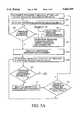
- FIG. 3is a block diagram of a pressure transducer shown in FIG. 2, in accord with the present invention.
- FIG. 4is a block diagram of processing circuitry shown in FIG. 2, in accord with the present invention.
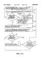
- FIGS. 5A-5Cis a flow chart showing the operation of a computer program for determining the weight of a load lifted by the forklift shown in FIG. 1, in accord with the present invention.
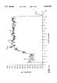
- FIG. 6is a graph of time versus pressure of sample measurements observed, employing the present invention in the forklift of FIG. 1 while lifting a load.
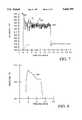
- FIG. 7is a graph of time versus pressure of sample measurements taken employing the present invention in the forklift shown in FIG. 1 during a tare lift.
- FIG. 8is a graph of time versus pressure showing a rate of decay of pressure in the fluid of the hydraulic system shown in FIG. 2.
- FIGS. 9A-9Bis a flow chart showing the operation of a computer program for determining the pressure fluctuations of hydraulic fluid of the system shown in FIG. 2, in accord with the present invention.
- the present inventionmay be mounted and used on a number of different hydraulic lifting devices.
- a conventional forklift 10having a main body 12 supported by a plurality of wheels 14 including an operator compartment 16 having a control console 18 to control the operation of the forklift 10.
- Attached proximate to the control console 18is a vertically extending mast 20.
- a carriage 22is movably attached to the mast 20 and includes a plurality of forks 24, extending perpendicular from the mast away from the control console 18.
- Lift-chains 26are attached to the carriage 22 and extend over sprockets 28 which are positioned proximate to one end of the mast 20, opposite to the plurality of wheels 14.
- a hollow cylinder 30 housing a piston 32 and hydraulic fluid 34is attached to the mast 20, with one end of the lift-chains being attached to the cylinder 30.
- the piston 32is connected to the sprockets 28 and movement of the cylinder 30 causes the carriage 22 to move along the mast 20.
- Hydraulic fluid 34 in the cylinder 30is disposed between the piston 32 and one end of the cylinder 30 having an aperture 36, with the piston 32 imparting a force upon the hydraulic fluid 34 proportional to a weight associated with the forks 24.
- a hydraulic control system 38is in fluid communication with the aperture to regulate ingress and egress of the hydraulic fluid 34 with respect to the cylinder 30.
- the control system 38includes a control valve 40, high 48 and low 50 pressure reservoirs, hydraulic pump 52 and forklift motor 54.
- Control valve 40has first 42 and second 44 valve elements, both of which are connected to aperture 36 via fluid line 46.
- High pressure fluid reservoir 48is in fluid communication with valve element 42
- low pressure fluid reservoir 50is in fluid communication with valve element 44.
- Valve elements 42 and 44allow the fluid line 46 to be selectively placed in flow communication with high 48 and low 50 pressure reservoirs, respectively.
- Hydraulic pump 52is connected between the high pressure 48 and low pressure 50 reservoirs and is powered by the forklift motor 54.
- Upon opening valve element 42hydraulic fluid flows from the high pressure reservoir 48 to enter the cylinder 30. This moves piston 32 away from aperture 36 causing lift-chains 26 to raise the carriage 22 toward the sprockets 28. Lowering the carriage 22 is achieved by closing valve element 42 and opening valve element 44, allowing hydraulic fluid 34 to exit cylinder 30 and enter low pressure reservoir 50.
- a pressure transducer 56is placed in fluid communication with fluid line 46, and a digital computer and display 58 is in electrical communication with the pressure transducer 56 to determine, from the fluid 34 pressure, the weight of a load on the forks 24.
- the pressure transducer 56is shown as having a silicon based piezo-resistive transducing unit 60 in a Wheatstone bridge configuration.
- a current source 62is coupled to supply between 1 and 1.5 mA of current to the transducing unit 60.
- a change in pressure experienced by the transducing unit 60results in a proportional change in a voltage measured at unit 60's output, which is coupled to a differential amplifier 64.
- the output of the transducing unit 60may range from 0 to 100 mV, corresponding to a range of pressures from 0 psi to 5000 psi.
- the output of the transducing unit 60is amplified by amplifier 64 and fixed to a rail voltage V REF supplied by a voltage reference circuit 66.
- the output of amplifier 64is fixed between 0 and 5 volts.
- the output of amplifier 64is coupled to an analog-to-digital converter 68 which digitizes the amplified signal and produces a 12 bit binary number, ranging from 0 to 4096. The range of the binary numbers corresponds to the full scale of voltage, i.e. 0 to 5 volts.
- the output of the converter 68is coupled to a microprocessor 70.
- a switch 72disposed between the amplifier 64 and the converter 68, is under control of the microprocessor 70 to essentially provide a second input to the analog-to-digital converter 68. Coupled to one pole of the switch is a thermistor 74 positioned to measure the ambient temperature of the pressure transducer 56 and fluid 34.
- the measurements made by the transducing unitmay be compensated to overcome the consequences of the transducing unit's temperature characteristics.
- a non-volatile memory element 76which stores the temperature characteristics of the transducing unit 60. For example, both magnitude and the zero offset of the output from transducer unit 60 varies with temperature. The changes are calculated using a three point curve fitting algorithm, and the constants associated with the calculation are stored in memory element 76.
- the output of the pressure transducer 56is typically a digital data stream transmitted in serial format at 9600 baud, along line 78.
- the digital computer and display 58is shown as including a buffer 80 coupled to line 78 to receive the digital data stream from the pressure transducer 56.
- the output of the buffer 80is coupled to the main processor 82.
- the main processor 82controls the operations of the pressure transducer 56 via microprocessor 70, including the conversion of data by converter 68 and relay of the converted data to buffer 80.
- Coupled to the main processor 82are first 84 and second 86 memories.
- the first program memorytypically stores the program used to determine the weight from the pressure data relayed from the pressure transducer 56, discussed more fully below with respect to FIGS. 5A-C and 6.
- the programis typically stored in a read only memory, but any type of storage device may be employed.
- Second data memorystores the data corresponding to measurements of the pressure of the fluid 34 in the cylinder 30.
- the main processor 82drives the pressure transducer 56 to take approximately 120 pressure measurements per second during a predetermined time period referred to as a sampling period.
- the sampling periodis typically on the order of two to three seconds.
- data memory 86is configured to store at least twenty seconds worth of data. It is a circular buffer so that data may be automatically overwritten upon commencement of a new sampling period. In this fashion, data memory 86 stores a sequence of pressure measurements, with each measurement corresponding to a unique increment of time in the sequence. Each increment is associated with a unique address in the data memory 86.
- An example of a sequence of pressure measurementsis shown as 146 in FIG. 6, discussed more fully below.
- a display 88is also included to provide a visual representation of the weight of a load present on the forks 24.
- a switch 90is provided to obtain a tare weight at the forks 24, i.e. when the forks 24 are empty.
- a plurality of switches 92are operationally coupled to the main processor 82 that enables a user to enter the dimensions of the cylinder 30 and piston 32, thereby calibrating the digital computer and display 58.
- the weight of a load supported by forks 24is determined as a function of the fluid 34 pressure in the cylinder 30 as follows: ##EQU1## where W is the weight of the total load; A is the effective area of the piston 32; g is the acceleration of gravity; d 2 x/dt 2 is the acceleration of the forks 24; B is a frictional constant of the piston seal; and dx/dt is the velocity of the forks.
- the tare weight W T of the forks 24is subtracted from the total weight, providing the weight of the load lifted.
- the tare weight W Tmay either be determined in advance and recorded in program memory 84, or it may be determined as described below with respect to FIG.
- Fluid pressure in the housingis proportional to the seal resistance, which in turn is proportional to the velocity of the movement of the carriage 22 along mast 20.
- a process program stored in program memory 84is employed to process a data stream in real time, thereby determining when the acceleration of the carriage 22 has ceased.
- the main processor 82operates on the program to access data, determining a baseline indicating that a lift has begun.
- steps 96, 98 and 100ascertain increments of time in the sequence 146 corresponding to a stationary position of the forks 24.
- twenty pressure measurementswill be read from data memory 86 at step 96.
- the absolute value of the maximum pressure variance between any two pressure measurementsis determined.
- the programdetermines whether the pressure variance among the twenty pressure measurements exceeds pressure level P 1 .
- Pressure level P 1lies within a predetermined range, typically zero to seven pounds per-square-inch. If the twenty pressure measurements do not exceed P 1 , the program will determine that the forks are stationary and proceed with step 106. If the program determines that the variance exceeds P 1 , then the forks are not stationary, causing the program to proceed with step 102. At step 102, an additional pressure measurement is read, which corresponds to an additional increment of time in sequence 146. At step 104, the pressure variance among the last twenty pressure measurements is determined, at which point step 100 is again repeated. Steps 100, 102 and 104 are repeated until the conditions of step 100 are satisfied, i.e., until the absolute value of the pressure variance in twenty samples is less than P 1 .
- step 106an additional pressure measurement is read, which corresponds to an additional increment of time in the sequence 146.
- step 108the program determines the variance between the last twenty pressure measurements read, at step 104, and the additional pressure measurements read at step 106.
- step 110the program determines whether the variance measured at step 108 exceeds a pressure level P 50 , which is typically fifty pounds per-square-inch. If not, then an additional pressure measurement may be read at step 112, at which point the program determines whether twenty additional pressure measurements have been read at step 114. If not, steps 108, 110, 112 and 114 are repeated until the conditions of step 110 are satisfied. After step 114 indicates that twenty additional pressure measurements have been read, the program returns to step 104, where the program searches for a new baseline. If the parameters of step 110 have been satisfied, then the starting point of the lift is identified, shown as A on sequence 146, and the program proceeds to step 116.
- step 116twenty-one additional increments of pressure measurements are read following the increment of the last pressure measurement read at step 112.
- step 118the local maximum of the pressure measurements read at step 116 is identified.
- the programidentifies the highest pressure measured, P h , among the pressure measurements read at step 116, and at step 122, it is determined whether P h is a local maximum.
- P his a local maximum
- the programidentifies the measurement as P max . If P h is not a local maximum, P h is cleared at step 123, and steps 116, 118 and 120 are repeated until P h is identified as a local maximum at step 122.
- P his cleared at step 123, and steps 116, 118 and 120 are repeated until P h is identified as a local maximum at step 122.
- an additional pressure measurementis read, and the local maximum among the last twenty-one pressure measurements is identified at steps 126 and 128.
- the programidentifies the central pressure measurement P e among the last twenty-one read, i.e., the pressure measurement read at step 126 located so that ten pressure measurements before and after P e are read.
- the programdetermines whether the central pressure measurement P e exceeds P max .
- step 134determines whether P e is a local maximum.
- P eis identified as P max if it is a local maximum, thereby erasing the previous P max identified at step 124. Thereafter, the program repeats steps 126, 128, 130 and 132. If P e is not a local maximum, P max is cleared, and the program returns to step 116. In this fashion, the program dynamically determines P max , as it reads the pressure measurements from memory 86.
- P maxis shown on sequence 146 and represents the increment at which the effects of acceleration, pressure surges and other mechanical disturbances are maximized. Pressure measurements are analyzed following the increment during the sequence 146 at which the effects of acceleration are maximized.
- P maxis an important parameter to identify because at increments subsequent to P max , the velocity of the carriage 22 on the mast 20 is constant. Measuring the pressure when the velocity of the carriage 22 is constant provides a more accurate pressure measurement.
- N 2is approximately 240 pressure measurements, although any number may suffice. From this, an accurate weight measurement may be made.
- the local maxima identified in the sequence following P maxare important to filter unwanted mechanical disturbances which affect the accuracy of the measurement. Specifically, it was recognized that certain mechanical disturbances manifested in sequence 146 as vibrational frequencies. A dominant frequency from 5 to 10 Hz and a subdominant frequency of 20 to 50 Hz is found to be modulated onto sequence 146. The dominant frequency is believed to be caused by stretch in the lift-chain 26 and caused as much as a 20% error in the measurement of weight.
- the programfilters the unwanted frequencies by separating the first local maximum from P max by at least 10 increments (0.08 second). Subsequent local maxima must be spaced by the same amount from an adjacent local maximum among the 240 additional pressure measurements.
- a sub-set of twenty-one increments of pressure measurementsare read, with the pressure measurement closest to the previous local maximum being separated by at least ten increments. From the subset of increments, the highest pressure level detected is identified as a local maximum. This iteration is repeated over the sequence of increments following P max .
- the closest local maximum following P maxis identified as P A , which represents the increment during the lift at which the velocity of the carriage 22 is no longer changing and the vibrational and pressure characteristics of the system have stabilized.
- the remaining local maximaare identified as P 1 , P 2 , P 3 . . . P N , which, when coupled with P A , define the remaining sequence. As shown in FIG.
- P maxcorresponds to increment 108 and local maxima P A , P 1 , P 2 , P 3 , P 4 , P 5 and P 6 correspond to increments 134, 154, 176 and 197, 220, 240 and 237, respectively.
- P Acorresponds to 1.1 seconds of sampling time.
- the local maxima of the remaining sequenceare then averaged at step 144, producing the total pressure, P TO , measured.
- Averaging step 144reduces the error caused by the subdominant vibration.
- an adjustmentis made for pressure fluctuations in the fluid 34 to produce an adjusted pressure, P AD , measurement, discussed more fully below.
- the "tare" pressure, P TAis subtracted from the P AD pressure to obtain the net pressure, P N , attributable to the load on the forks 24, from which the weight is calculated.
- the weightis displayed and then the program determines whether the measurement is a tare pressure measurement at step 152. If so, the measurement is stored in memory 84 at step 154.
- a pressure measurementmay be identified as tare pressure in response to a user depressing one of switches 92, indicating the same.
- the tare pressureis typically determined by measuring the pressure associated with the forks 24 empty. This is achieved by moving the forks 24 at a constant velocity along the mast 20, as described above. To obtain accurate measurements, it is necessary that the "tare” be performed at the same velocity as the measurement for a load supported on the forks. To ensure the velocity of the forks 24s' movement occurs at the same velocity, valve elements 42 and 44 are placed in the fully opened position when actuated, and the motor 54 is maintained at a constant RPM, typically idling, while the pressure transducer 56 records pressure measurements.
- a problem encountered in this arrangementconcerned pressure fluctuations in the hydraulic system, resulting from the movement of the pump valves and a reduction in the idling of motor 54 which drives pump 52.
- fluid 34 from reservoir 48enters cylinder 30 via valve element 42 and aperture 36. This causes a slight pressure decrease in reservoir 48.
- Pump 52requires a few moments to compensate for the pressure decrease by pumping fluid 34 from reservoir 50 into reservoir 48. It has been found that as much as a one pound per-square-inch per-second decay in pressure may be detected by pressure transducer 56. Thus, for any given force exerted on the fluid 34 by piston 32, a plurality, or range of, pressure values may be detected by the pressure transducer 56, resulting in as much as a nine pound error in weight measurement.
- the decay rateis error correction used to calculate P AD at step 148.
- This programmay be stored in program memory 84 along with the program described above with respect to FIGS. 5A-C and 6, or it may be incorporated into the same.
- the decay rateis typically measured during a "tare" lift, i.e., no load is supported by the forks 24 and shown as sequence 246.
- a pressure measurement P Zsixty increments from P max , is identified, and pressure measurements corresponding to ⁇ sixty increments therefrom are averaged.
- An additional pressure measurementis identified at 100 increments from P Z and pressure measurements ⁇ 60 increments are averaged, providing a curve 247, shown in FIG. 8.
- the difference between the average at P Z and the average measurement, P 100is measured.
- the lift time, P L , between increment P Z and measurement P 100is divided into the difference of averaged values to ascertain the decay rate in psi/sec.
- the lift timemay be obtained by any conventional means in the digital art, for example, by using the internal clock of main processor 82.
- a decay rate of approximately 2.67 psi/secis demonstrated.
- the "tare" weight and the decay rateis determined before lifting a load by depressing switch 90, shown in FIG. 4.
- the decay ratemay be stored in memory and incorporated into the calculations of the weight of a load supported by forks 24, as shown in step 146 of FIG. 5C. This allows determining the weight of a load supported by the forks of a forklift with less than 1% error.
- Steps 394 to 316are identical to steps 94 to 116 of the program described above with respect to FIGS. 5A-C.
- step 318the highest pressure measured, P h , among the pressure measurements read in step 316 is identified.
- step 120240 additional pressure measurements are measured at increments of time following the group comprising pressure measurements read at step 316.
- step 322the local maxima among the 240 pressure measurements is determined in the same fashion as described above with respect to FIGS. 5A-C.
- step 324it is determined whether a pressure measurement among the 240 read at step 320 exceeds P h . If not, then the program determines whether P h is a local maximum at step 326, and if so, P h is identified as P max at step 328. If P h is not found to be a local maximum, then the program returns to step 316.
- step 324if at step 324, at least one pressure measurement exceeds P h , the program continues to identify the local maximum having the highest pressure measurement as P max , at step 330. After P max is identified, the program proceeds with steps 332, 334, 336, 338, 340, 342 and 344, which are identical to steps 142, 144, 146, 148, 150, 152 and 154 with respect to FIG. 5.
Landscapes
- Physics & Mathematics (AREA)
- General Physics & Mathematics (AREA)
- Life Sciences & Earth Sciences (AREA)
- Engineering & Computer Science (AREA)
- Geology (AREA)
- Mechanical Engineering (AREA)
- Structural Engineering (AREA)
- Forklifts And Lifting Vehicles (AREA)
Abstract
Description
Claims (29)
Priority Applications (1)
| Application Number | Priority Date | Filing Date | Title |
|---|---|---|---|
| US08/583,283US5666295A (en) | 1996-01-05 | 1996-01-05 | Apparatus and method for dynamic weighing of loads in hydraulically operated lifts |
Applications Claiming Priority (1)
| Application Number | Priority Date | Filing Date | Title |
|---|---|---|---|
| US08/583,283US5666295A (en) | 1996-01-05 | 1996-01-05 | Apparatus and method for dynamic weighing of loads in hydraulically operated lifts |
Publications (1)
| Publication Number | Publication Date |
|---|---|
| US5666295Atrue US5666295A (en) | 1997-09-09 |
Family
ID=24332460
Family Applications (1)
| Application Number | Title | Priority Date | Filing Date |
|---|---|---|---|
| US08/583,283Expired - Fee RelatedUS5666295A (en) | 1996-01-05 | 1996-01-05 | Apparatus and method for dynamic weighing of loads in hydraulically operated lifts |
Country Status (1)
| Country | Link |
|---|---|
| US (1) | US5666295A (en) |
Cited By (50)
| Publication number | Priority date | Publication date | Assignee | Title |
|---|---|---|---|---|
| US5973274A (en)* | 1998-04-03 | 1999-10-26 | Snap-On Tools Company | Vehicle weighing system for dynamometer |
| US5994650A (en)* | 1996-03-28 | 1999-11-30 | Bt Industries Ab | Safety system for lift trucks |
| EP0969271A1 (en)* | 1998-07-04 | 2000-01-05 | Pfreundt GmbH & Co. KG | Weighing method for hydraulically moveable components |
| WO2000014479A1 (en)* | 1996-04-12 | 2000-03-16 | Holometrics, Inc. | Laser scanning system and applications |
| US6056501A (en)* | 1997-11-14 | 2000-05-02 | Kabushiki Kaisha Toyoda Jidoshokki Seisakusho | Axle tilt control apparatus for industrial vehicles |
| US6135694A (en)* | 1997-09-30 | 2000-10-24 | Crown Equipment Corporation | Travel and fork lowering speed control based on fork load weight/tilt cylinder operation |
| WO2001014167A1 (en)* | 1999-08-19 | 2001-03-01 | Compagnie Erhel Hydris | Improvement to vehicle lifting tail gate |
| US6232566B1 (en)* | 1999-07-12 | 2001-05-15 | Gagetek Technologies, Holdings Company | Apparatus in a lifting device for reducing error in weight measurements |
| RU2181880C2 (en)* | 1995-05-24 | 2002-04-27 | Зе Фоксборо Кампэни | Gear to position electric elements with differentiated tightness of compartments |
| US6390751B2 (en)* | 1998-10-07 | 2002-05-21 | Cascade Corporation | Adaptive load-clamping system |
| US6414251B1 (en) | 1999-04-19 | 2002-07-02 | Breck Colquett | Weighing apparatus and method having automatic tolerance analysis and calibration |
| RU2186353C1 (en)* | 2001-07-12 | 2002-07-27 | Государственное унитарное предприятие Центральный аэрогидродинамический институт им. профессора Н.Е. Жуковского | Gear to manufacture capacitive pressure transducers and process of their assembly |
| US20030047389A1 (en)* | 2001-08-21 | 2003-03-13 | Nippon Yusoki Co., Ltd. | Lift truck |
| US6552279B1 (en) | 2000-09-28 | 2003-04-22 | Caterpillar Inc | Method and apparatus configured to perform viscosity compensation for a payload measurement system |
| US20030141117A1 (en)* | 2002-01-08 | 2003-07-31 | Clyde Jones | Automated weight measurement system |
| US6627825B1 (en)* | 1998-12-21 | 2003-09-30 | Tek Solutions Pty Ltd | Hydraulic weighing apparatus and method |
| US20030235489A1 (en)* | 2002-06-24 | 2003-12-25 | Hoff William H. | Load control system for tandem pallet truck |
| US20040094336A1 (en)* | 2001-03-09 | 2004-05-20 | Axel Weyer | Method and device for weighing the content of a metallurgical vessel, particularly the content of a distributing launder in steel continuous casting installations |
| US20040133384A1 (en)* | 2002-12-19 | 2004-07-08 | Jungheinrich Aktiengesellschaft | Method for determining the weight of a load upon a load support means of a hydraulic lifting device |
| US20040158380A1 (en)* | 2003-02-07 | 2004-08-12 | Farber Bruce W. | Hydraulic stabilizer system and process for monitoring load conditions |
| US20040200644A1 (en)* | 2003-04-08 | 2004-10-14 | Alan Paine | Safe load lifting measurement device |
| US20040267474A1 (en)* | 2003-06-30 | 2004-12-30 | Drake J. Michael | Method and apparatus for performing temperature compensation for a payload measurement system |
| US20050051367A1 (en)* | 2003-08-26 | 2005-03-10 | Hagen Martin H. | Bin lifting and weigh scale arrangement |
| US20050092530A1 (en)* | 2003-10-30 | 2005-05-05 | Rice Thomas S. | Apparatus and method for weighting objects on a fork lift truck |
| US20050282669A1 (en)* | 2004-06-19 | 2005-12-22 | Arthur Bauer | Belt tensioning arrangement and belt drive with such a belt tensioning arrangement |
| US20060060409A1 (en)* | 2004-09-23 | 2006-03-23 | Dammeyer Karl L | Electronically controlled valve for a materials handling vehicle |
| US20060070773A1 (en)* | 2004-10-06 | 2006-04-06 | Caterpillar Inc. | Payload overload control system |
| US20060100808A1 (en)* | 2003-06-30 | 2006-05-11 | Lueschow Kevin J | Method and apparatus for performing temperature compensation for a payload measurement system |
| US7089803B1 (en) | 2005-10-28 | 2006-08-15 | Huber Engineered Woods Llc | Panel performance testing system |
| WO2006128454A1 (en)* | 2005-06-03 | 2006-12-07 | Torben Winther Hansen | Method of weight determination of a load carried by a lifter of a lifting device and weighing device |
| US20080169131A1 (en)* | 2005-03-15 | 2008-07-17 | Shu Takeda | Device And Method For Measuring Load Weight On Working Machine |
| US20090127031A1 (en)* | 2007-10-23 | 2009-05-21 | Paul John Corder | Weight Calculation Compensation |
| US20090240403A1 (en)* | 2005-12-23 | 2009-09-24 | Hwang Joon Ha | Control system and method for electric-powered forklifts |
| US20090292427A1 (en)* | 2008-05-26 | 2009-11-26 | Kabushiki Kaisha Toyota Jidoshokki | load weight measuring device for a multi-stage mast forklift truck |
| EP1953114A3 (en)* | 2007-02-01 | 2010-01-27 | STILL WAGNER GmbH | Industrial truck with a hydraulically liftable load pick-up |
| US20100278620A1 (en)* | 2009-05-04 | 2010-11-04 | Rimsa James R | Refuse receptacle lifter mounting/weighing assembly |
| US20110031040A1 (en)* | 2008-05-01 | 2011-02-10 | Ricon Corp. | Static pressure anti-stow logic for platform wheelchair lifts |
| US20110206483A1 (en)* | 2010-02-19 | 2011-08-25 | Gauthier Steven | Weight sensing method and apparatus for forklifts |
| CN102431936A (en)* | 2011-12-19 | 2012-05-02 | 苏州先锋物流装备科技有限公司 | Piling car with limiting function |
| US8924103B2 (en) | 2011-02-16 | 2014-12-30 | Crown Equipment Corporation | Materials handling vehicle estimating a speed of a movable assembly from a lift motor speed |
| US9200432B1 (en)* | 2014-06-09 | 2015-12-01 | Caterpillar Inc. | Method and system for estimating payload weight with hydraulic fluid temperature compensation |
| US20150354177A1 (en)* | 2014-06-09 | 2015-12-10 | Caterpillar Inc. | Method and System for Estimating Payload Weight with Tilt Position Compensation |
| EP2987763A1 (en)* | 2014-08-22 | 2016-02-24 | Linde Material Handling GmbH | Method for monitoring overload in an industrial truck |
| US20160113598A1 (en)* | 2013-05-01 | 2016-04-28 | Koninklijke Philips N.V. | Imaging system subject support tabletop deflection delta correction |
| EP3037378A1 (en)* | 2014-12-22 | 2016-06-29 | STILL GmbH | Method for hydraulic pressure measurement in an industrial truck |
| US20170029256A1 (en)* | 2015-07-30 | 2017-02-02 | Danfoss Power Solutions Gmbh & Co Ohg | Load dependent electronic valve actuator regulation and pressure compensation |
| US20170370075A1 (en)* | 2014-12-24 | 2017-12-28 | Cqms Pty Ltd | System and method of calculating a payload weight |
| US9964428B2 (en)* | 2008-10-09 | 2018-05-08 | Cascade Corporation | Equalized hydraulic clamp force control |
| US10030676B2 (en) | 2014-04-23 | 2018-07-24 | Hyster—Yale Group, Inc. | Hydraulic fluid supply apparatus and methods |
| US11377334B2 (en)* | 2018-02-28 | 2022-07-05 | Jungheinrich Aktiengesellschaft | Industrial truck with at least one hydraulic mast lift cylinder |
Citations (14)
| Publication number | Priority date | Publication date | Assignee | Title |
|---|---|---|---|---|
| US4635739A (en)* | 1985-06-25 | 1987-01-13 | Caterpillar Inc. | Payload monitor |
| US4824315A (en)* | 1986-07-21 | 1989-04-25 | Zoller-Kipper Gmbh | Equipment for emptying containers statement as to rights to inventions made under federally-sponsored research and development |
| US4854406A (en)* | 1986-10-20 | 1989-08-08 | Breakthru Industries, Inc. | Weighing system |
| US5064008A (en)* | 1990-03-05 | 1991-11-12 | Wray-Tech Instruments, Inc. | Hydraulic control system for weighing |
| US5065829A (en)* | 1990-03-05 | 1991-11-19 | Wray-Tech Instruments, Inc. | Hydraulic control system for weighing |
| US5065828A (en)* | 1990-03-05 | 1991-11-19 | Wray-Tech Instruments, Inc. | Hydraulic control system for weighing |
| US5105895A (en)* | 1990-08-20 | 1992-04-21 | Caterpillar Inc. | Method and apparatus for identifying load cycle functions |
| US5139101A (en)* | 1991-04-10 | 1992-08-18 | Wray-Tech Instruments, Inc. | Hydraulic control system for weighing and two-way valve therefor |
| US5195418A (en)* | 1991-04-10 | 1993-03-23 | Wray-Tech Instruments, Inc. | Hydraulic control system for weighting and two-way valve therefor |
| US5208753A (en)* | 1991-03-28 | 1993-05-04 | Acuff Dallas W | Forklift alignment system |
| US5210706A (en)* | 1989-08-25 | 1993-05-11 | Tokyo Electric Co. Ltd. | Device for measuring a physical force |
| US5243512A (en)* | 1991-05-20 | 1993-09-07 | Westinghouse Electric Corp. | Method and apparatus for minimizing vibration |
| US5327347A (en)* | 1984-04-27 | 1994-07-05 | Hagenbuch Roy George Le | Apparatus and method responsive to the on-board measuring of haulage parameters of a vehicle |
| US5329441A (en)* | 1991-02-05 | 1994-07-12 | Mitsubishi Jukogyo Kabushiki Kaisha | Hydraulic control device for a work machine |
- 1996
- 1996-01-05USUS08/583,283patent/US5666295A/ennot_activeExpired - Fee Related
Patent Citations (15)
| Publication number | Priority date | Publication date | Assignee | Title |
|---|---|---|---|---|
| US5327347A (en)* | 1984-04-27 | 1994-07-05 | Hagenbuch Roy George Le | Apparatus and method responsive to the on-board measuring of haulage parameters of a vehicle |
| US4635739A (en)* | 1985-06-25 | 1987-01-13 | Caterpillar Inc. | Payload monitor |
| US4824315A (en)* | 1986-07-21 | 1989-04-25 | Zoller-Kipper Gmbh | Equipment for emptying containers statement as to rights to inventions made under federally-sponsored research and development |
| US4854406A (en)* | 1986-10-20 | 1989-08-08 | Breakthru Industries, Inc. | Weighing system |
| US5210706A (en)* | 1989-08-25 | 1993-05-11 | Tokyo Electric Co. Ltd. | Device for measuring a physical force |
| US5064008A (en)* | 1990-03-05 | 1991-11-12 | Wray-Tech Instruments, Inc. | Hydraulic control system for weighing |
| US5065829A (en)* | 1990-03-05 | 1991-11-19 | Wray-Tech Instruments, Inc. | Hydraulic control system for weighing |
| US5065828A (en)* | 1990-03-05 | 1991-11-19 | Wray-Tech Instruments, Inc. | Hydraulic control system for weighing |
| US5105895A (en)* | 1990-08-20 | 1992-04-21 | Caterpillar Inc. | Method and apparatus for identifying load cycle functions |
| US5329441A (en)* | 1991-02-05 | 1994-07-12 | Mitsubishi Jukogyo Kabushiki Kaisha | Hydraulic control device for a work machine |
| US5208753A (en)* | 1991-03-28 | 1993-05-04 | Acuff Dallas W | Forklift alignment system |
| US5195418A (en)* | 1991-04-10 | 1993-03-23 | Wray-Tech Instruments, Inc. | Hydraulic control system for weighting and two-way valve therefor |
| US5287885A (en)* | 1991-04-10 | 1994-02-22 | Wray-Tech Instruments, Inc. | Hydraulic control system for weighing and two-way valve therefor |
| US5139101A (en)* | 1991-04-10 | 1992-08-18 | Wray-Tech Instruments, Inc. | Hydraulic control system for weighing and two-way valve therefor |
| US5243512A (en)* | 1991-05-20 | 1993-09-07 | Westinghouse Electric Corp. | Method and apparatus for minimizing vibration |
Non-Patent Citations (2)
| Title |
|---|
| "Lift Truck Scales" brochure, Weigh-Tronix, Inc., 2320 Airport Boulvard, P.O. Box 1501, Santa Rosa, CA 95402-1501. |
| Lift Truck Scales brochure, Weigh Tronix, Inc., 2320 Airport Boulvard, P.O. Box 1501, Santa Rosa, CA 95402 1501.* |
Cited By (79)
| Publication number | Priority date | Publication date | Assignee | Title |
|---|---|---|---|---|
| RU2181880C2 (en)* | 1995-05-24 | 2002-04-27 | Зе Фоксборо Кампэни | Gear to position electric elements with differentiated tightness of compartments |
| US5994650A (en)* | 1996-03-28 | 1999-11-30 | Bt Industries Ab | Safety system for lift trucks |
| WO2000014479A1 (en)* | 1996-04-12 | 2000-03-16 | Holometrics, Inc. | Laser scanning system and applications |
| US6135694A (en)* | 1997-09-30 | 2000-10-24 | Crown Equipment Corporation | Travel and fork lowering speed control based on fork load weight/tilt cylinder operation |
| US6056501A (en)* | 1997-11-14 | 2000-05-02 | Kabushiki Kaisha Toyoda Jidoshokki Seisakusho | Axle tilt control apparatus for industrial vehicles |
| US5973274A (en)* | 1998-04-03 | 1999-10-26 | Snap-On Tools Company | Vehicle weighing system for dynamometer |
| EP0969271A1 (en)* | 1998-07-04 | 2000-01-05 | Pfreundt GmbH & Co. KG | Weighing method for hydraulically moveable components |
| US6390751B2 (en)* | 1998-10-07 | 2002-05-21 | Cascade Corporation | Adaptive load-clamping system |
| US6627825B1 (en)* | 1998-12-21 | 2003-09-30 | Tek Solutions Pty Ltd | Hydraulic weighing apparatus and method |
| US6414251B1 (en) | 1999-04-19 | 2002-07-02 | Breck Colquett | Weighing apparatus and method having automatic tolerance analysis and calibration |
| US6232566B1 (en)* | 1999-07-12 | 2001-05-15 | Gagetek Technologies, Holdings Company | Apparatus in a lifting device for reducing error in weight measurements |
| WO2001014167A1 (en)* | 1999-08-19 | 2001-03-01 | Compagnie Erhel Hydris | Improvement to vehicle lifting tail gate |
| US6552279B1 (en) | 2000-09-28 | 2003-04-22 | Caterpillar Inc | Method and apparatus configured to perform viscosity compensation for a payload measurement system |
| US20040094336A1 (en)* | 2001-03-09 | 2004-05-20 | Axel Weyer | Method and device for weighing the content of a metallurgical vessel, particularly the content of a distributing launder in steel continuous casting installations |
| RU2186353C1 (en)* | 2001-07-12 | 2002-07-27 | Государственное унитарное предприятие Центральный аэрогидродинамический институт им. профессора Н.Е. Жуковского | Gear to manufacture capacitive pressure transducers and process of their assembly |
| US20030047389A1 (en)* | 2001-08-21 | 2003-03-13 | Nippon Yusoki Co., Ltd. | Lift truck |
| US7165819B2 (en) | 2001-08-21 | 2007-01-23 | Nippon Yusoki Co., Ltd. | Lift truck |
| US20060025915A1 (en)* | 2001-08-21 | 2006-02-02 | Nippon Yusoki Co., Ltd. | Lift truck |
| US20030141117A1 (en)* | 2002-01-08 | 2003-07-31 | Clyde Jones | Automated weight measurement system |
| US6835900B2 (en) | 2002-01-08 | 2004-12-28 | Clyde Jones | Automated weight measurement system |
| US20030235489A1 (en)* | 2002-06-24 | 2003-12-25 | Hoff William H. | Load control system for tandem pallet truck |
| US20040133384A1 (en)* | 2002-12-19 | 2004-07-08 | Jungheinrich Aktiengesellschaft | Method for determining the weight of a load upon a load support means of a hydraulic lifting device |
| US6868364B2 (en)* | 2002-12-19 | 2005-03-15 | Jungheinrich Aktiengesellschaft | Method for determining the weight of a load upon a load support means of a hydraulic lifting device |
| US6785597B1 (en) | 2003-02-07 | 2004-08-31 | Wiggins Lift Co., Inc. | Hydraulic stabilizer system and process for monitoring load conditions |
| US20040158380A1 (en)* | 2003-02-07 | 2004-08-12 | Farber Bruce W. | Hydraulic stabilizer system and process for monitoring load conditions |
| US20040200644A1 (en)* | 2003-04-08 | 2004-10-14 | Alan Paine | Safe load lifting measurement device |
| US20040267474A1 (en)* | 2003-06-30 | 2004-12-30 | Drake J. Michael | Method and apparatus for performing temperature compensation for a payload measurement system |
| US7480579B2 (en) | 2003-06-30 | 2009-01-20 | Caterpillar Inc. | Method and apparatus for performing temperature compensation for a payload measurement system |
| US20060100808A1 (en)* | 2003-06-30 | 2006-05-11 | Lueschow Kevin J | Method and apparatus for performing temperature compensation for a payload measurement system |
| US20050051367A1 (en)* | 2003-08-26 | 2005-03-10 | Hagen Martin H. | Bin lifting and weigh scale arrangement |
| US7211747B2 (en)* | 2003-08-26 | 2007-05-01 | Shred-Tech Corporation | Bin lifting and weigh scale arrangement |
| US20050092530A1 (en)* | 2003-10-30 | 2005-05-05 | Rice Thomas S. | Apparatus and method for weighting objects on a fork lift truck |
| US7026557B2 (en)* | 2003-10-30 | 2006-04-11 | Mettler-Toledo | Apparatus and method for weighting objects on a fork lift truck |
| US20050282669A1 (en)* | 2004-06-19 | 2005-12-22 | Arthur Bauer | Belt tensioning arrangement and belt drive with such a belt tensioning arrangement |
| US20060060409A1 (en)* | 2004-09-23 | 2006-03-23 | Dammeyer Karl L | Electronically controlled valve for a materials handling vehicle |
| US7344000B2 (en) | 2004-09-23 | 2008-03-18 | Crown Equipment Corporation | Electronically controlled valve for a materials handling vehicle |
| US7276669B2 (en) | 2004-10-06 | 2007-10-02 | Caterpillar Inc. | Payload overload control system |
| US20060070773A1 (en)* | 2004-10-06 | 2006-04-06 | Caterpillar Inc. | Payload overload control system |
| US20080169131A1 (en)* | 2005-03-15 | 2008-07-17 | Shu Takeda | Device And Method For Measuring Load Weight On Working Machine |
| CN101223424B (en)* | 2005-06-03 | 2011-08-10 | 托尔文·温瑟·汉森 | Method for determining the weight of a load carried by a lift of a lifting device and weighing device |
| US20080314649A1 (en)* | 2005-06-03 | 2008-12-25 | Torben Winther Hansen | Method of Weight Determination of a Load Carried by a Lifter of a Lifting Device and Weighing Device |
| EA011053B1 (en)* | 2005-06-03 | 2008-12-30 | Торбен Винтер Хансен | Method of weight determination of a load carried by a lifter of a lifting device and weighing device |
| WO2006128454A1 (en)* | 2005-06-03 | 2006-12-07 | Torben Winther Hansen | Method of weight determination of a load carried by a lifter of a lifting device and weighing device |
| US7795547B2 (en) | 2005-06-03 | 2010-09-14 | Torben Winther Hansen | Method of weight determination of a load carried by a lifter of a lifting device and weighing device |
| US7089803B1 (en) | 2005-10-28 | 2006-08-15 | Huber Engineered Woods Llc | Panel performance testing system |
| US20090240403A1 (en)* | 2005-12-23 | 2009-09-24 | Hwang Joon Ha | Control system and method for electric-powered forklifts |
| EP1953114A3 (en)* | 2007-02-01 | 2010-01-27 | STILL WAGNER GmbH | Industrial truck with a hydraulically liftable load pick-up |
| US20090127031A1 (en)* | 2007-10-23 | 2009-05-21 | Paul John Corder | Weight Calculation Compensation |
| US8126619B2 (en)* | 2007-10-23 | 2012-02-28 | Actronic Limited | Weight calculation compensation |
| US8816225B2 (en)* | 2008-05-01 | 2014-08-26 | Ricon Corp. | Static pressure anti-stow logic for platform wheelchair lifts |
| US20110031040A1 (en)* | 2008-05-01 | 2011-02-10 | Ricon Corp. | Static pressure anti-stow logic for platform wheelchair lifts |
| US8265836B2 (en) | 2008-05-26 | 2012-09-11 | Kabushiki Kaisha Toyota Jidoshokki | Load weight measuring device for a multi-stage mast forklift truck |
| US20090292427A1 (en)* | 2008-05-26 | 2009-11-26 | Kabushiki Kaisha Toyota Jidoshokki | load weight measuring device for a multi-stage mast forklift truck |
| EP2128077A1 (en)* | 2008-05-26 | 2009-12-02 | Kabushiki Kaisha Toyota Jidoshokki | A load weight measuring device for a multi-stage mast forklift truck |
| US9964428B2 (en)* | 2008-10-09 | 2018-05-08 | Cascade Corporation | Equalized hydraulic clamp force control |
| US11300441B2 (en) | 2008-10-09 | 2022-04-12 | Cascade Corporation | Equalized hydraulic clamp force control |
| US10900825B2 (en) | 2008-10-09 | 2021-01-26 | Cascade Corporation | Equalized hydraulic clamp force control |
| USRE50500E1 (en) | 2008-10-09 | 2025-07-22 | Cascade Corporation | Equalized hydraulic clamp force control |
| US20100278620A1 (en)* | 2009-05-04 | 2010-11-04 | Rimsa James R | Refuse receptacle lifter mounting/weighing assembly |
| US8779306B2 (en)* | 2010-02-19 | 2014-07-15 | Methode Electronics, Inc. | Weight sensing method and apparatus for forklifts |
| US20110206483A1 (en)* | 2010-02-19 | 2011-08-25 | Gauthier Steven | Weight sensing method and apparatus for forklifts |
| US8924103B2 (en) | 2011-02-16 | 2014-12-30 | Crown Equipment Corporation | Materials handling vehicle estimating a speed of a movable assembly from a lift motor speed |
| US8935058B2 (en) | 2011-02-16 | 2015-01-13 | Crown Equipment Corporation | Materials handling vehicle estimating a speed of a movable assembly from a lift motor speed |
| US9296598B2 (en) | 2011-02-16 | 2016-03-29 | Crown Equipment Corporation | Materials handling vehicle measuring electric current flow into/out of a hydraulic system motor |
| US9394151B2 (en) | 2011-02-16 | 2016-07-19 | Crown Equipment Corporation | Materials handling vehicle monitoring a pressure of hydraulic fluid within a hydraulic structure |
| US9751740B2 (en) | 2011-02-16 | 2017-09-05 | Crown Equipment Corporation | Materials handling vehicle estimating a speed of a movable assembly from a lift motor speed |
| CN102431936A (en)* | 2011-12-19 | 2012-05-02 | 苏州先锋物流装备科技有限公司 | Piling car with limiting function |
| US20160113598A1 (en)* | 2013-05-01 | 2016-04-28 | Koninklijke Philips N.V. | Imaging system subject support tabletop deflection delta correction |
| US10030676B2 (en) | 2014-04-23 | 2018-07-24 | Hyster—Yale Group, Inc. | Hydraulic fluid supply apparatus and methods |
| US9464403B2 (en)* | 2014-06-09 | 2016-10-11 | Caterpillar Inc. | Method and system for estimating payload weight with tilt position compensation |
| US20150354177A1 (en)* | 2014-06-09 | 2015-12-10 | Caterpillar Inc. | Method and System for Estimating Payload Weight with Tilt Position Compensation |
| US9200432B1 (en)* | 2014-06-09 | 2015-12-01 | Caterpillar Inc. | Method and system for estimating payload weight with hydraulic fluid temperature compensation |
| EP2987763A1 (en)* | 2014-08-22 | 2016-02-24 | Linde Material Handling GmbH | Method for monitoring overload in an industrial truck |
| EP3037378A1 (en)* | 2014-12-22 | 2016-06-29 | STILL GmbH | Method for hydraulic pressure measurement in an industrial truck |
| US20170370075A1 (en)* | 2014-12-24 | 2017-12-28 | Cqms Pty Ltd | System and method of calculating a payload weight |
| US10982415B2 (en)* | 2014-12-24 | 2021-04-20 | Cqms Pty Ltd | System and method of calculating a payload weight |
| US20170029256A1 (en)* | 2015-07-30 | 2017-02-02 | Danfoss Power Solutions Gmbh & Co Ohg | Load dependent electronic valve actuator regulation and pressure compensation |
| US10183852B2 (en)* | 2015-07-30 | 2019-01-22 | Danfoss Power Solutions Gmbh & Co Ohg | Load dependent electronic valve actuator regulation and pressure compensation |
| US11377334B2 (en)* | 2018-02-28 | 2022-07-05 | Jungheinrich Aktiengesellschaft | Industrial truck with at least one hydraulic mast lift cylinder |
Similar Documents
| Publication | Publication Date | Title |
|---|---|---|
| US5666295A (en) | Apparatus and method for dynamic weighing of loads in hydraulically operated lifts | |
| JP4884464B2 (en) | Method for measuring weight of baggage carried by lifter of lifting device, and weighing device | |
| US5182712A (en) | Dynamic payload monitor | |
| US7967244B2 (en) | Onboard aircraft weight and balance system | |
| US4230196A (en) | Load weighing and accumulating system and method for hydraulic loader | |
| RU2537728C2 (en) | Weight registration system for load suspended on lifting crane cable | |
| EP2511678A1 (en) | Measurement system for a material transfer vehicle | |
| JPH10512044A (en) | Computer monitor management system for load-carrying vehicles | |
| US5677498A (en) | Vehicle axle load weighing system | |
| JPH04344427A (en) | Dynamic-chargeable-load monitoring apparatus | |
| JPH05502292A (en) | Apparatus and method for monitoring payloads | |
| US4586366A (en) | Method and apparatus for measuring driving resistance and velocity of piles during driving | |
| NL8401015A (en) | SYSTEM FOR MEASURING THE WEIGHT OF A HELICOPTER. | |
| EP3449227B1 (en) | Method of weight determination of a load carried by a lifter of a lifting device and weighing device | |
| EP2910912A1 (en) | Improved monitoring system | |
| US20050092530A1 (en) | Apparatus and method for weighting objects on a fork lift truck | |
| JPH05501009A (en) | Truck load weighing method and device | |
| US6232566B1 (en) | Apparatus in a lifting device for reducing error in weight measurements | |
| US4779461A (en) | Method of and apparatus for measuring and recording the drop height of a container in transit | |
| EP0246363B1 (en) | Method and apparatus for weighing loads lifted by hydraulic devices | |
| JP4149874B2 (en) | Construction machine load measuring device | |
| JP2626667B2 (en) | Loading weight detection device | |
| JPS6180016A (en) | Cargo balance of vehicle with cargo loading platform | |
| SE524212C8 (en) | Method and device for determining the weight of load in a mining vehicle | |
| SE524212C2 (en) | Method and apparatus for determining the weight of cargo in a mining vehicle |
Legal Events
| Date | Code | Title | Description |
|---|---|---|---|
| AS | Assignment | Owner name:SENTEK PRODUCTS, CALIFORNIA Free format text:ASSIGNMENT OF ASSIGNORS INTEREST;ASSIGNOR:BRUNS, ROBERT W.;REEL/FRAME:008452/0389 Effective date:19970403 | |
| AS | Assignment | Owner name:GAGETEK COMPANY, CALIFORNIA Free format text:CHANGE OF NAME;ASSIGNOR:SENTEK PRODUCTS;REEL/FRAME:008960/0319 Effective date:19971208 | |
| CC | Certificate of correction | ||
| AS | Assignment | Owner name:GAGETEK TECHNOLOGIES LLC, CALIFORNIA Free format text:ASSIGNMENT OF ASSIGNORS INTEREST;ASSIGNOR:GAGETEK COMPANY;REEL/FRAME:011648/0031 Effective date:20010306 Owner name:GAGETEK TECHNOLOGIES HOLDINGS COMPANY, CALIFORNIA Free format text:ASSIGNMENT OF ASSIGNORS INTEREST;ASSIGNOR:GAGETEK TECHNOLOGIES, LLC;REEL/FRAME:011648/0365 Effective date:20010306 | |
| REMI | Maintenance fee reminder mailed | ||
| AS | Assignment | Owner name:GAGETEK TECHNOLOGIES HOLDINGS COMPANY, CALIFORNIA Free format text:ASSIGNMENT OF ASSIGNORS INTEREST;ASSIGNOR:GAGETEK TECHNOLOGIES, LLC;REEL/FRAME:011796/0129 Effective date:20010306 | |
| FPAY | Fee payment | Year of fee payment:4 | |
| SULP | Surcharge for late payment | ||
| REMI | Maintenance fee reminder mailed | ||
| LAPS | Lapse for failure to pay maintenance fees | ||
| STCH | Information on status: patent discontinuation | Free format text:PATENT EXPIRED DUE TO NONPAYMENT OF MAINTENANCE FEES UNDER 37 CFR 1.362 | |
| FP | Lapsed due to failure to pay maintenance fee | Effective date:20050909 |