US5666101A - High-efficiency apparatus for measuring operational parameters and times of vehicles running around a racetrack - Google Patents
High-efficiency apparatus for measuring operational parameters and times of vehicles running around a racetrackDownload PDFInfo
- Publication number
- US5666101A US5666101AUS08/562,243US56224395AUS5666101AUS 5666101 AUS5666101 AUS 5666101AUS 56224395 AUS56224395 AUS 56224395AUS 5666101 AUS5666101 AUS 5666101A
- Authority
- US
- United States
- Prior art keywords
- station
- racetrack
- frequency
- antenna
- vehicles
- Prior art date
- Legal status (The legal status is an assumption and is not a legal conclusion. Google has not performed a legal analysis and makes no representation as to the accuracy of the status listed.)
- Expired - Lifetime
Links
- 230000005540biological transmissionEffects0.000claimsdescription14
- 238000012545processingMethods0.000claimsdescription6
- 238000004804windingMethods0.000claimsdescription4
- 239000004020conductorSubstances0.000claimsdescription3
- 238000001514detection methodMethods0.000claims2
- 238000005259measurementMethods0.000description3
- 238000006243chemical reactionMethods0.000description2
- 238000009434installationMethods0.000description2
- 238000000034methodMethods0.000description2
- 230000003321amplificationEffects0.000description1
- 238000013459approachMethods0.000description1
- 230000004888barrier functionEffects0.000description1
- 238000010276constructionMethods0.000description1
- 230000008878couplingEffects0.000description1
- 238000010168coupling processMethods0.000description1
- 238000005859coupling reactionMethods0.000description1
- 239000013078crystalSubstances0.000description1
- 230000002045lasting effectEffects0.000description1
- 238000012423maintenanceMethods0.000description1
- 238000012544monitoring processMethods0.000description1
- 238000003199nucleic acid amplification methodMethods0.000description1
- 238000001228spectrumMethods0.000description1
- 238000012360testing methodMethods0.000description1
Images


Classifications
- G—PHYSICS
- G07—CHECKING-DEVICES
- G07C—TIME OR ATTENDANCE REGISTERS; REGISTERING OR INDICATING THE WORKING OF MACHINES; GENERATING RANDOM NUMBERS; VOTING OR LOTTERY APPARATUS; ARRANGEMENTS, SYSTEMS OR APPARATUS FOR CHECKING NOT PROVIDED FOR ELSEWHERE
- G07C1/00—Registering, indicating or recording the time of events or elapsed time, e.g. time-recorders for work people
- G07C1/22—Registering, indicating or recording the time of events or elapsed time, e.g. time-recorders for work people in connection with sports or games
- G07C1/24—Race time-recorders
Definitions
- This inventionrelates to a high-efficiency apparatus for measuring operational parameters and times of vehicles running around a racetrack.
- apparatus and recording systemswhich are based on the use of photocells being linked to PC's through a so-called telephone loop to record the pass of each vehicle.
- the apparatus employed in conventional measuring apparatushave operating rates which are liable to much interference from the traffic volume of data being transmitted, thereby they require intense maintenance by skilled personnel.
- the underlying technical problem of this inventionis to provide an apparatus for measuring operational parameters and times of vehicles running around a racetrack in real time, which has such structural and functional features as to enable prompt identification of any of the vehicles in the race while providing measurements of partial and overall speed and travel times over the racetrack for each of the vehicles.
- Another object of the inventionis to enable transmission and computer processing of the measurement information from each vehicle.
- a high-efficiency apparatus for real time measuring of parameters and operational times of vehicles running around a racetrackis provided.
- At least one detecting stationis arranged at a location along the racetrack and is set up to both receive and transmit radio frequency signals both from/to a transceiver unit installed on each vehicle.
- the transmitting from the transceiver unitis in response to the transmitting from the detecting station.
- the stationis provided with an electronic radio frequency-converter for transmitting and modulating the received signals over a wide band coaxial cable.
- a plurality of detecting stationsare arranged at selected locations along the racetrack.
- a transceiver unitis mounted on each vehicle and is operative to both receive and transmit information from/to each station.
- a loop connection structureinterconnects the stations with a central processing unit.
- FIG. 1is a diagramatic representation of an apparatus according to the invention
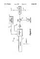
- FIG. 2is another diagramatic view, showing a detail of the apparatus in FIG. 1;
- FIG. 3is a diagramatic view showing a further detail of the apparatus in FIG. 1;
- FIG. 4is a diagramatic representation of a data processing unit associated with the apparatus in FIG. 1.
- an apparatus embodying this inventionis an apparatus embodying this invention and being adapted to measure, in real time, operational parameters and times of vehicles 2, such as racing cars running around a race track.
- Trackmeans here any generic racetrack, path, or closed-loop course, such as a motordrome, along which vehicles of varying description may have to face speed and/or endurance trials and compete with one another in a race.
- the apparatus 1comprises a set of operational units which are structurally independent of but interact with one another.
- detecting stations 10installed at selected locations on one side of the track.
- a preferred embodiment of the installationprovides no less than thirty two stations 10 along the course which may be placed behind the conventional bumping barrier.
- FIG. 1Shown in FIG. 1 is a section 3 of a track, on one side whereof there are arranged two identical detecting stations whose constructions will be described in detail hereinafter.
- Each vehicle 2mounts a transceiver unit 5 operative to receive and transmit RF information from/to each station 10.
- the unit 5is secured under the bodyframe 6 of the vehicle 2.
- Each detecting station 10includes an antenna 8 lying transversely to the track. Specifically, the antennae 8 would be buried beneath the track surface such that the vehicles 2 will cross the antennae along their travel path from an overlying position, as shown schematically in FIG. 1.
- an interconnection looped or segmented structure 15wherethrough all of the stations 10 are connected to a central processing unit 12 operative to supply, for each vehicle 2, full information pertaining to partial and overall travel times around the racetrack.
- the structure 15is advantageously comprised of a wide band coaxial cable interconnecting the various stations 10 and the central unit 12.
- the transceiver unit 5Upon one of the vehicles 2 in the race according to its travel path crossing or moving past one of the antennae 8, the transceiver unit 5 will pick up a signal from station 10. Preferably, this signal would be emitted at a frequency of 153.6 kHz or 143.6 kHz.
- the transceiver unit 5On receiving this signal, the transceiver unit 5 will be driven, in turn, to emit an RF signal, which signal is emitted at a single selected frequency of vehicle identification in the 1.2 GHz band.
- the station 10picks up the return signal on the same antenna 8.
- the detecting stationtransmits the received signals to the central unit 12.
- the transmissiontakes place over the wide band coaxial cable 15 interconnecting all of the detecting stations 10.
- the information received by the central unit 12is processed to obtain the parameter of the time when a vehicle 2 has moved past a given station 10.
- each detecting station 10will be described with reference in particular to the example of FIG. 2.
- each station 10includes an antenna 8 comprising a section of a cable conductor 9, essentially bent into a U-shape and having opposite ends which are run to an interface 11.
- the cable 9is buried under the track surface transversely to the running direction thereof, and the interface 11 is housed and powered within a sealed case connected to the remaining circuitry of station 10 through a multipolar connector.
- the interface 11incorporates electronic circuitry, not shown because conventional, for driving the RF emission from the antenna 8 under control by control signals F1, F2 which are received on an input terminal 13.
- Another input terminal 13ais arranged to receive test signals of the antenna operability.
- the signals F1 and F2come from a low-frequency oscillator, such as a so-called crystal, installed at the station 10 and being controlled and powered over a six-way bus line.
- a low-frequency oscillatorsuch as a so-called crystal
- the antenna 8is, therefore, set up for emitting the signals F1, F2 at two pre-determined frequencies: 153.6 kHz ⁇ 100 Hz and 143.6 kHz ⁇ 100 Hz.
- the antenna 8also receives signals in the 1.2 GHz band.
- a high-frequency amplifier 14is connected downstream from the interface 11.
- the station 10further includes a mixer 16 having a first input connected to the amplifier 14 output and a second input receiving a signal generated by a local oscillator 17 which operates at 1.1435 GHz.
- the mixer 16is adapted to convert the signal received in the 1.2 GHz frequency band to a useful signal for transmission over the coaxial cable 15.
- the modulatorallows, therefore, of the output signal from the mixer 16 to be modulated such that each of the different stations 10 can be identified by the central unit 12 during a data transmission.
- the one difference between the various stations 10is given by the modulation of the signal that arrives at the central unit from each of them over the wide band cable 15.
- the working frequency of the cable 15is within the range of 71.750 MHz to 137.075 MHz. Consequently, the carrier frequency identifying each of the vehicles 2, being emitted by the corresponding transceiver unit 5, will be converted through the mixer 16 to enable its transmission over the cable 15. The frequency of the output signal will depend, therefore, on which vehicle is moving above the antenna 8.
- a carrier frequency of 1.215 GHzis associated with a vehicle
- the corresponding carrier on the wide band cablewould be 71.75 MHz.
- the frequency modulation wherewith these signals are transmitted over the cable 15will enable the central unit 12 to also identify the emitting station 10.
- the output impedance to the coaxial cable of the modulator 20is selected to be 75 R, thereby when the unit 5 on the vehicle is 500 millimeters above the antenna 8, the signal received by the central unit will be a level of -20 dBm or lower.
- any other services for which the cable 15 may be utilizedwould not interfere with the band used for the above-mentioned measurement.
- the station 10is installed inside a sealed case affording a protection rating of IP65, and is suitable for operation within a temperature range of -25° C. to +50° C.
- the electronic circuitryis supplied a voltage in the 37 to 65 Volts range at 50 Hz from the coaxial cable itself.
- the transceiver unit 5While co-operating directly with the detecting station 10, the transceiver unit 5 is illustrated in detail by FIG. 3.
- Said unit 5comprises an RF signal receiver 30 having a first winding tuned to the frequency of 153.6 kHz and a second winding tuned to 143.6 kHz.
- a meter-amplifier 21Connected downstream from the receiver 30 is a meter-amplifier 21 which has an output connected to a control circuit portion 40.
- a threshold detector 22having an input connected to the amplifier 21 output.
- the amplifier 21 outputis connected to the input of a differential amplifier 23 with an associated comparator 24.
- the respective outputs of the threshold detector 22 and the comparator 24are connected to corresponding inputs of a logic gate 25 of the AND type which drives, through an output 26 thereof, a high-frequency transmitter 27 operative to emit signals in the 1.2 GHz band through an antenna 31.
- the frequency band allocated to this transmissionis in the range of 1.215 GHz to 1.280325 GHz; in this way, a selected identification frequency can be associated with each vehicle.
- a frequency of 1.15 GHzthere may be associated with a first vehicle a frequency of 1.15 GHz, and with a second vehicle, another frequency of 1.2155 GHz, 625 kHz apart from the former.
- the unit 5is also provided with a frequency discriminator 28 which is connected to the receiver 30 output and operative to generate a signal U1 indicative of the vehicle having moved past, over an antenna 8.
- a second signal U2 from the output of the AND gate 25indicates with antenna 8 has been run over.
- the transmitter 27Upon the receiver 30 picking up the signal at 153.6 kHz or 143.6 kHz from the antenna 8, the transmitter 27 is operated to emit a carrier in the 1.2 GHz band concurrently with the amplitude peak of the received signal.
- the unit 5is designed to transmit telemetric format information via a suitable modulator.
- the function of the threshold detector 22is to define a minimum signal level above which the transmitter 27 should be operated. Concurrently therewith, the peak of the detected signal is identified by the amplifier 23 and its associated comparator to also identify the transmission frequency of the received signal.
- the unit 5By having the unit 5 fitted under the body frame 6 of the vehicle 2, its vertical axis can be arranged to lie substantially normal to the axis of the vehicle wheels. Thus, the RF transmission between the unit 5 and the antenna 8 is favored.
- the input side of the unit 12receives one end of the coaxial wide band cable 15, and through a frequency conversion followed by amplification at an intermediate frequency by an interface 33, makes an electric signal IF available which can be analyzed by a module 32.
- the modules 32are structurally identical with one another, and the unit 12 is formed by two sets of fifty such modules each: each module being paired with one vehicle in the race.
- Each module 32comprises a receiver 34 tuned to a frequency which corresponds to that of a given vehicle 2.
- Said receiver 34comprises a demodulator 35 having an output connected to a microprocessor 37 of the integrated type which is operated on the basis of a timing pulse CK.
- a circuit portion 38is also provided for analyzing the spectrum of the signal IF and allowing, on an output 39, the identification and demodulation of any telemetric transmissions of information directed to an external unit.
- the coupling between the demodulator 35 and the microprocessor 37provides for the former of these components to supply on respective outputs a digital signal indicating which of the detecting stations 10 is transmitting over the coaxial cable 15, as well as which signal has been picked up on a vehicle moving past that station.
- each module 32will output a series of digital information, preferably in the ASCII code, relating to an identification code of the vehicle, a code identifying the detecting station 10, and the acknowledgment of that said vehicle has run past the station at a given time.
- This informationis used by an electronic processor, not shown because conventional, which is supplied the signals output by all of the various modules 32 to calculate the partial and overall times.
- the central unit 12is able as such to compute the partial and overall travel times around the course of at least a hundred vehicles competing with one another.
- the measuring accuracyis on the order of one thousandth of a second for vehicles which can attain a top speed of 400 kilometers per hour.
- the apparatus of this inventionallows each vehicle running around a racetrack to be identified in real time, while also recording its partial and overall run times. In addition, it allows of the transmission of parameters relating to engine, electric, or aerodynamic performance as issued by monitoring units, sensors or transducers installed on the vehicle.
- a major advantagecomes from the circuit being split through a plurality of measuring points, which enables the racing record of each vehicle to be substantially re-constructed.
- a further advantageis the ability to have a racetrack equipped with the apparatus of this invention on a permanent basis, thus avoiding the costly installation and adjustment operations entailed by conventional systems in current use.
Landscapes
- Physics & Mathematics (AREA)
- General Physics & Mathematics (AREA)
- Arrangements For Transmission Of Measured Signals (AREA)
Abstract
Description
This application is a continuation of application Ser. No. 08/050,491, filed as PCT/EP91/02419, Dec. 16, 1991, published as WO92/10811, Jun. 25, 1992, and now abandoned.
This invention relates to a high-efficiency apparatus for measuring operational parameters and times of vehicles running around a racetrack.
In the specific applicative field of this invention a well-recognized requirement is that information on the partial and overall travel times of a running vehicle should be provided in real time.
The difficulties encountered in filling this demand are intensified where several vehicles competent in a race are running around the same one track. In fact, it is not so easy to identify each of the vehicles and record all the run times around the track.
While some solutions have been proposed in the prior art to meet the above-mentioned requirement, these have shown to be less than fully satisfactory.
For instance, apparatus and recording systems have been known which are based on the use of photocells being linked to PC's through a so-called telephone loop to record the pass of each vehicle.
Other approaches make use of an RF transmitter installed on each vehicle in a race and a single receiver antenna buried beneath the track finish line.
While serving their purpose to some extent, the above prior solutions have presently become obsolete because they can only operate with a limited number of vehicles running at one time. In neither instances, moreover, can such conventional solutions provide for the transmission of engine, electrical or aerodynamic parameters of the running vehicles.
In addition, the apparatus employed in conventional measuring apparatus have operating rates which are liable to much interference from the traffic volume of data being transmitted, thereby they require intense maintenance by skilled personnel.
It should be further added that such prior apparatus are no permanent intallations, but are installed temporarily on a racetrack according to necessity, which entails considerable adjustment work by skilled personnel, lasting several hours, before each race.
The underlying technical problem of this invention is to provide an apparatus for measuring operational parameters and times of vehicles running around a racetrack in real time, which has such structural and functional features as to enable prompt identification of any of the vehicles in the race while providing measurements of partial and overall speed and travel times over the racetrack for each of the vehicles.
Another object of the invention is to enable transmission and computer processing of the measurement information from each vehicle.
This technical problem is solved by an apparatus as indicated, being characterized as in the appended claims.
The features and advantages of an apparatus according to the invention will become apparent from the following detailed description of an embodiment thereof, given by way of illustration and not of limitation with reference to the accompanying drawings.
A high-efficiency apparatus for real time measuring of parameters and operational times of vehicles running around a racetrack is provided. At least one detecting station is arranged at a location along the racetrack and is set up to both receive and transmit radio frequency signals both from/to a transceiver unit installed on each vehicle. The transmitting from the transceiver unit is in response to the transmitting from the detecting station. The station is provided with an electronic radio frequency-converter for transmitting and modulating the received signals over a wide band coaxial cable.
In an embodiment of the invention, a plurality of detecting stations are arranged at selected locations along the racetrack. A transceiver unit is mounted on each vehicle and is operative to both receive and transmit information from/to each station. A loop connection structure interconnects the stations with a central processing unit.
In the drawings:
FIG. 1 is a diagramatic representation of an apparatus according to the invention;
FIG. 2 is another diagramatic view, showing a detail of the apparatus in FIG. 1;
FIG. 3 is a diagramatic view showing a further detail of the apparatus in FIG. 1; and
FIG. 4 is a diagramatic representation of a data processing unit associated with the apparatus in FIG. 1.
With reference to the drawing figures, generally and schematically shown at 1 is an apparatus embodying this invention and being adapted to measure, in real time, operational parameters and times ofvehicles 2, such as racing cars running around a race track.
Track means here any generic racetrack, path, or closed-loop course, such as a motordrome, along which vehicles of varying description may have to face speed and/or endurance trials and compete with one another in a race.
Theapparatus 1 comprises a set of operational units which are structurally independent of but interact with one another.
Provided along the track may beplural detecting stations 10 installed at selected locations on one side of the track. A preferred embodiment of the installation provides no less than thirty twostations 10 along the course which may be placed behind the conventional bumping barrier.
Shown in FIG. 1 is asection 3 of a track, on one side whereof there are arranged two identical detecting stations whose constructions will be described in detail hereinafter.
Eachvehicle 2 mounts atransceiver unit 5 operative to receive and transmit RF information from/to eachstation 10.
In a preferred embodiment, theunit 5 is secured under thebodyframe 6 of thevehicle 2.
Each detectingstation 10 includes anantenna 8 lying transversely to the track. Specifically, theantennae 8 would be buried beneath the track surface such that thevehicles 2 will cross the antennae along their travel path from an overlying position, as shown schematically in FIG. 1.
Also provided is an interconnection looped or segmentedstructure 15 wherethrough all of thestations 10 are connected to acentral processing unit 12 operative to supply, for eachvehicle 2, full information pertaining to partial and overall travel times around the racetrack.
Thestructure 15 is advantageously comprised of a wide band coaxial cable interconnecting thevarious stations 10 and thecentral unit 12.
The method of operation of the inventive apparatus will be now described briefly: further on, this method will be discussed in greater detail.
Upon one of thevehicles 2 in the race according to its travel path crossing or moving past one of theantennae 8, thetransceiver unit 5 will pick up a signal fromstation 10. Preferably, this signal would be emitted at a frequency of 153.6 kHz or 143.6 kHz.
On receiving this signal, thetransceiver unit 5 will be driven, in turn, to emit an RF signal, which signal is emitted at a single selected frequency of vehicle identification in the 1.2 GHz band.
Thestation 10 picks up the return signal on thesame antenna 8.
Through a frequency conversion, the detecting station transmits the received signals to thecentral unit 12. The transmission takes place over the wide bandcoaxial cable 15 interconnecting all of the detectingstations 10.
The information received by thecentral unit 12 is processed to obtain the parameter of the time when avehicle 2 has moved past a givenstation 10.
Now, the structure of each detectingstation 10 will be described with reference in particular to the example of FIG. 2.
As mentioned above, eachstation 10 includes anantenna 8 comprising a section of a cable conductor 9, essentially bent into a U-shape and having opposite ends which are run to aninterface 11. The cable 9 is buried under the track surface transversely to the running direction thereof, and theinterface 11 is housed and powered within a sealed case connected to the remaining circuitry ofstation 10 through a multipolar connector.
Theinterface 11 incorporates electronic circuitry, not shown because conventional, for driving the RF emission from theantenna 8 under control by control signals F1, F2 which are received on aninput terminal 13. Anotherinput terminal 13a is arranged to receive test signals of the antenna operability.
The signals F1 and F2 come from a low-frequency oscillator, such as a so-called crystal, installed at thestation 10 and being controlled and powered over a six-way bus line.
Theantenna 8 is, therefore, set up for emitting the signals F1, F2 at two pre-determined frequencies: 153.6 kHz±100 Hz and 143.6 kHz±100 Hz.
Theantenna 8 also receives signals in the 1.2 GHz band. For picking up such signals, a high-frequency amplifier 14 is connected downstream from theinterface 11.
Thestation 10 further includes amixer 16 having a first input connected to theamplifier 14 output and a second input receiving a signal generated by alocal oscillator 17 which operates at 1.1435 GHz. Themixer 16 is adapted to convert the signal received in the 1.2 GHz frequency band to a useful signal for transmission over thecoaxial cable 15.
Accordingly, the difference between the values of the signals at the respective inputs of themixer 16 will be addressed to the input of amodulator 20 connected in thecoaxial cable 15 to enable the transmission of information to thecentral unit 12.
The modulator allows, therefore, of the output signal from themixer 16 to be modulated such that each of thedifferent stations 10 can be identified by thecentral unit 12 during a data transmission. In fact, the one difference between thevarious stations 10 is given by the modulation of the signal that arrives at the central unit from each of them over thewide band cable 15.
The working frequency of thecable 15 is within the range of 71.750 MHz to 137.075 MHz. Consequently, the carrier frequency identifying each of thevehicles 2, being emitted by the correspondingtransceiver unit 5, will be converted through themixer 16 to enable its transmission over thecable 15. The frequency of the output signal will depend, therefore, on which vehicle is moving above theantenna 8.
For instance, if a carrier frequency of 1.215 GHz is associated with a vehicle, the corresponding carrier on the wide band cable would be 71.75 MHz. Likewise, to a second vehicle having an identifying frequency of 1.2155 GHz, there would correspond a frequency of 72.25 MHz downstream from themixer 16.
In any case, the frequency modulation wherewith these signals are transmitted over thecable 15 will enable thecentral unit 12 to also identify the emittingstation 10.
The output impedance to the coaxial cable of themodulator 20 is selected to be 75 R, thereby when theunit 5 on the vehicle is 500 millimeters above theantenna 8, the signal received by the central unit will be a level of -20 dBm or lower.
Any other services for which thecable 15 may be utilized would not interfere with the band used for the above-mentioned measurement.
It should be mentioned for completeness that thestation 10 is installed inside a sealed case affording a protection rating of IP65, and is suitable for operation within a temperature range of -25° C. to +50° C. The electronic circuitry is supplied a voltage in the 37 to 65 Volts range at 50 Hz from the coaxial cable itself.
While co-operating directly with the detectingstation 10, thetransceiver unit 5 is illustrated in detail by FIG. 3.
It is powered, in a manner known per se, from resident batteries, but alternative powering from the vehicle standard battery is also contemplated.
Connected downstream from thereceiver 30 is a meter-amplifier 21 which has an output connected to acontrol circuit portion 40.
Provided on the one side in theportion 40 is athreshold detector 22 having an input connected to theamplifier 21 output. On the other side, theamplifier 21 output is connected to the input of adifferential amplifier 23 with an associatedcomparator 24.
The respective outputs of thethreshold detector 22 and thecomparator 24 are connected to corresponding inputs of alogic gate 25 of the AND type which drives, through anoutput 26 thereof, a high-frequency transmitter 27 operative to emit signals in the 1.2 GHz band through anantenna 31.
Specifically, the frequency band allocated to this transmission is in the range of 1.215 GHz to 1.280325 GHz; in this way, a selected identification frequency can be associated with each vehicle.
As an example, there may be associated with a first vehicle a frequency of 1.15 GHz, and with a second vehicle, another frequency of 1.2155 GHz, 625 kHz apart from the former.
Accordingly, by selecting frequencies which lie 500 kHz or 625 kHz apart, it becomes possible to identify, within the above-specified band, up to over one hundred vehicles competing on the same racetrack.
Theunit 5 is also provided with afrequency discriminator 28 which is connected to thereceiver 30 output and operative to generate a signal U1 indicative of the vehicle having moved past, over anantenna 8. A second signal U2 from the output of the ANDgate 25 indicates withantenna 8 has been run over.
These signals U1, U2 are addressed to aserial connector 29 which is connected to a pair of inputs of thetransmitter 27 to supply information and a timing pulse where theunit 5 is used for telemetric transmissions at 256 kbaud.
Upon thereceiver 30 picking up the signal at 153.6 kHz or 143.6 kHz from theantenna 8, thetransmitter 27 is operated to emit a carrier in the 1.2 GHz band concurrently with the amplitude peak of the received signal.
Theunit 5 is designed to transmit telemetric format information via a suitable modulator.
The function of thethreshold detector 22 is to define a minimum signal level above which thetransmitter 27 should be operated. Concurrently therewith, the peak of the detected signal is identified by theamplifier 23 and its associated comparator to also identify the transmission frequency of the received signal.
By having theunit 5 fitted under thebody frame 6 of thevehicle 2, its vertical axis can be arranged to lie substantially normal to the axis of the vehicle wheels. Thus, the RF transmission between theunit 5 and theantenna 8 is favored.
With reference in particular to the example shown in FIG. 4, the structure and operation of thecentral unit 12 running to the various detectingstations 10 will be now described.
The input side of theunit 12 receives one end of the coaxialwide band cable 15, and through a frequency conversion followed by amplification at an intermediate frequency by aninterface 33, makes an electric signal IF available which can be analyzed by amodule 32.
Themodules 32 are structurally identical with one another, and theunit 12 is formed by two sets of fifty such modules each: each module being paired with one vehicle in the race.
Eachmodule 32 comprises areceiver 34 tuned to a frequency which corresponds to that of a givenvehicle 2. Saidreceiver 34 comprises ademodulator 35 having an output connected to amicroprocessor 37 of the integrated type which is operated on the basis of a timing pulse CK.
Acircuit portion 38 is also provided for analyzing the spectrum of the signal IF and allowing, on anoutput 39, the identification and demodulation of any telemetric transmissions of information directed to an external unit.
The coupling between the demodulator 35 and themicroprocessor 37 provides for the former of these components to supply on respective outputs a digital signal indicating which of the detectingstations 10 is transmitting over thecoaxial cable 15, as well as which signal has been picked up on a vehicle moving past that station.
The microprocessor will then supply, on anoutput 36, the above information in the RS232 serial format. That is, eachmodule 32 will output a series of digital information, preferably in the ASCII code, relating to an identification code of the vehicle, a code identifying the detectingstation 10, and the acknowledgment of that said vehicle has run past the station at a given time.
This information is used by an electronic processor, not shown because conventional, which is supplied the signals output by all of thevarious modules 32 to calculate the partial and overall times.
Thecentral unit 12 is able as such to compute the partial and overall travel times around the course of at least a hundred vehicles competing with one another.
The measuring accuracy is on the order of one thousandth of a second for vehicles which can attain a top speed of 400 kilometers per hour.
The apparatus of this invention allows each vehicle running around a racetrack to be identified in real time, while also recording its partial and overall run times. In addition, it allows of the transmission of parameters relating to engine, electric, or aerodynamic performance as issued by monitoring units, sensors or transducers installed on the vehicle.
A major advantage comes from the circuit being split through a plurality of measuring points, which enables the racing record of each vehicle to be substantially re-constructed.
A further advantage is the ability to have a racetrack equipped with the apparatus of this invention on a permanent basis, thus avoiding the costly installation and adjustment operations entailed by conventional systems in current use.
Claims (15)
1. A high-efficiency apparatus (1) for real time measuring parameters and operational times of vehicles (2) running around a racetrack, said apparatus comprising:
a plurality of detecting stations (10) arranged at selected locations along said racetrack and being set up to both receive and transmit radio frequency (RF) signals both to and from a transceiver unit (5) mounted on each said vehicle (2),
said transceiver unit operative to both receive and transmit information both to and from each said station (10), said transmitting from said transceiver unit being in response to said transmitting from said detecting station, said station being provided with electronic radio frequency-converter means (16,20) for transmitting and modulating the received signals over a wide band coaxial cable (15);
said apparatus further comprising;
said wide band coaxial cable (15) forming a loop connection structure whereby said stations are interconnected with a central processing unit (12); and,
said apparatus further comprising;
each said station (10) comprises a transceiver antenna (8), an interface (11) associated with the antenna, a high frequency amplifier (14) connected downstream from the interface, a signal mixer (16) having one input connected to the amplifier (14) output and a second input to receive a signal generated by an oscillator (17), and a modulator (20) connected in said coaxial cable (15) and driven by the output from the mixer (16).
2. An apparatus according to claim 1, characterized in that each said station (10) includes a different one of a plurality of antenna (8) laid across the racetrack.
3. An apparatus according to claim 2, characterized in that each different one of said plurality of antenna is buried under the racetrack surface.
4. An apparatus according to claim 3, characterized in that each antenna (8) comprises a section of a cable conductor (9) bent essentially into a U-shape and having the opposite ends of said cable conductor run to a drive/receive interface (11).
5. An apparatus according to claim 1, characterized in that each said station (10) is associated with a different one of a plurality of low-frequency oscillator (7) inputs connected to said interface (11) associated with said antenna (8) and whence interface drive pulses are drawn for RF transmission at least two discrete frequencies.
6. An apparatus according to claim 5, characterized in that said discrete frequencies are 153.6 kHz and 143.6 kHz.
7. An apparatus according to claim 1, characterized in that the signals received and transmitted from/to said transceiver unit are low and high frequency signals, respectively.
8. An apparatus according to claim 1, characterized in that said transceiver unit (5) comprises a low frequency receiver (30) and a high frequency transmitter (27).
9. An apparatus according to claim 8, characterized in that said transmitter (27) is linked operatively to the detection of a signal by said receiver (30).
10. An apparatus according to claim 1, characterized in that said central processing unit (12) comprises a plurality of structurally independent modules (32) corresponding in number to that of the vehicles (2) taking part in the racing event, each module being provided with a different one of a plurality of receivers (34) each of said ones of receivers tuned to a different one of a plurality of frequencies corresponding to that transmitted by one of a plurality of transceiver units (5) of one of a plurality of vehicles in the race and with one of a plurality of microprocessors (37) connected thereto to encode parameters identifying the specific one of said vehicles, the detecting station (10), and the time when said specific one of said vehicles has moved past said station.
11. An apparatus according to claim 8, characterized in that said transmitter (27) is linked operatively to the detection of a signal by said receiver (30).
12. An apparatus according to claim 8 characterized in that said receiver (30) comprises a first winding tuned to a frequency of 153.6 kHz and a second winding tuned to a frequency of 143.6 kHz.
13. An apparatus according to claim 11, characterized in that connected downstream from the receiver (30) is an amplifier (21) whose output is connected to a control circuit portion (40) comprising, on the one side, a threshold detector (22), and in parallel the other side, the series of a differential amplifier (23) and a comparator (24).
14. An apparatus according to claim 13, characterized in that connected downstream from said control portion (40) via a logic gate (26) is the high frequency transmitter (27).
15. An apparatus according to claim 11, wherein said transmitter (27) emits RF signals in the 1.2 GHz band.
Priority Applications (1)
| Application Number | Priority Date | Filing Date | Title |
|---|---|---|---|
| US08/562,243US5666101A (en) | 1990-12-14 | 1995-11-22 | High-efficiency apparatus for measuring operational parameters and times of vehicles running around a racetrack |
Applications Claiming Priority (8)
| Application Number | Priority Date | Filing Date | Title |
|---|---|---|---|
| IT22389/90 | 1990-12-14 | ||
| IT02238990AIT1244337B (en) | 1990-12-14 | 1990-12-14 | Highly efficient apparatus for recording operational times and parameters of vehicles on a race circuit |
| IT02238890AIT1244336B (en) | 1990-12-14 | 1990-12-14 | Highly efficient apparatus for recording operational times and parameters of vehicles on a race circuit |
| IT22388/90 | 1990-12-14 | ||
| IT22390/90 | 1990-12-14 | ||
| IT02239090AIT1244338B (en) | 1990-12-14 | 1990-12-14 | Highly efficient apparatus for recording operational times and parameters of vehicles on a race circuit |
| US5049193A | 1993-05-13 | 1993-05-13 | |
| US08/562,243US5666101A (en) | 1990-12-14 | 1995-11-22 | High-efficiency apparatus for measuring operational parameters and times of vehicles running around a racetrack |
Related Parent Applications (1)
| Application Number | Title | Priority Date | Filing Date |
|---|---|---|---|
| US5049193AContinuation | 1990-12-14 | 1993-05-13 |
Publications (1)
| Publication Number | Publication Date |
|---|---|
| US5666101Atrue US5666101A (en) | 1997-09-09 |
Family
ID=27452859
Family Applications (1)
| Application Number | Title | Priority Date | Filing Date |
|---|---|---|---|
| US08/562,243Expired - LifetimeUS5666101A (en) | 1990-12-14 | 1995-11-22 | High-efficiency apparatus for measuring operational parameters and times of vehicles running around a racetrack |
Country Status (1)
| Country | Link |
|---|---|
| US (1) | US5666101A (en) |
Cited By (34)
| Publication number | Priority date | Publication date | Assignee | Title |
|---|---|---|---|---|
| WO1998006184A1 (en)* | 1996-08-06 | 1998-02-12 | Forren Helmut R | Timing and scoring system |
| US5867089A (en) | 1996-09-03 | 1999-02-02 | Chrysler Corporation | Base-to-remotely controlled vehicle communications for automated durability road (ADR) facility |
| US5906647A (en) | 1996-09-03 | 1999-05-25 | Chrysler Corporation | Vehicle mounted guidance antenna for automated durability road (ADR) facility |
| US5974977A (en)* | 1997-09-29 | 1999-11-02 | Johnson Research & Development Company, Inc. | Magnetic propulsion toy system |
| US6020851A (en)* | 1997-10-06 | 2000-02-01 | Busack; Andrew J. | Auto race monitoring system |
| US6061614A (en)* | 1997-10-17 | 2000-05-09 | Amtech Systems Corporation | Electronic tag including RF modem for monitoring motor vehicle performance |
| US6107917A (en)* | 1998-10-16 | 2000-08-22 | Carrender; Curtis L. | Electronic tag including RF modem for monitoring motor vehicle performance with filtering |
| US6141620A (en) | 1996-09-03 | 2000-10-31 | Chrysler Corporation | Vehicle control system for automated durability road (ADR) facility |
| US6195090B1 (en)* | 1997-02-28 | 2001-02-27 | Riggins, Iii A. Stephen | Interactive sporting-event monitoring system |
| US6226572B1 (en)* | 1997-02-12 | 2001-05-01 | Komatsu Ltd. | Vehicle monitor |
| WO2001033530A1 (en)* | 1999-10-29 | 2001-05-10 | Wns-Europe.Com Ag | Positioning system for racing cars |
| US20020138587A1 (en)* | 1998-02-23 | 2002-09-26 | Koehler Steven M. | System and method for listening to teams in a race event |
| GB2376585A (en)* | 2001-06-12 | 2002-12-18 | Roke Manor Research | Determining position and speed |
| US6587759B2 (en) | 1997-01-28 | 2003-07-01 | American Calcar Inc. | Technique for effectively providing information responsive to a notable condition in a vehicle |
| US20040160355A1 (en)* | 2003-02-14 | 2004-08-19 | Bervoets Alfonsus Maria | System for determining a position of a moving transponder |
| EP1305898A4 (en)* | 2000-06-23 | 2005-01-12 | Sportvision Inc | Gps based tracking system |
| US6894601B1 (en) | 1998-10-16 | 2005-05-17 | Cummins Inc. | System for conducting wireless communications between a vehicle computer and a remote system |
| US20050148281A1 (en)* | 2003-11-17 | 2005-07-07 | Jorge Sanchez-Castro | Toy vehicles and play sets with contactless identification |
| US20050203651A1 (en)* | 2001-12-03 | 2005-09-15 | Fernando Vincenzini | System and process for charting the time and position of a contestant in a race |
| US20060087454A1 (en)* | 2004-10-07 | 2006-04-27 | Le Michael Q | Method and apparatus for remote control vehicle identification |
| US20060087427A1 (en)* | 2004-10-07 | 2006-04-27 | Le Micheal Q | Method and apparatus for remote control vehicle identification |
| US20060145891A1 (en)* | 2004-10-27 | 2006-07-06 | Bruce Silver | Racing control system |
| US7265663B2 (en) | 2001-11-28 | 2007-09-04 | Trivinci Systems, Llc | Multimedia racing experience system |
| US20100056238A1 (en)* | 2008-08-30 | 2010-03-04 | Terrell Ii James Richard | Racing management and information system |
| US20100089307A1 (en)* | 2007-01-23 | 2010-04-15 | Lotus Cars Limited | Sound synthesizer system for use in a vehicle having an internal combustion engine |
| SG162627A1 (en)* | 2008-12-11 | 2010-07-29 | Cs Racing Pte Ltd | A system and method for determining a quantitative result for a vehicle traversing a circuit, a monitoring device used in the system and method |
| US20100265801A1 (en)* | 2007-07-18 | 2010-10-21 | Times-7 Holdings Limited | Timing system and method of timing |
| WO2012019696A1 (en)* | 2010-08-12 | 2012-02-16 | Amusys Amusement Systems Electronics Gmbh | Device for detecting, monitoring and/or controlling racing vehicles |
| US8876572B2 (en) | 2011-08-29 | 2014-11-04 | Mattel, Inc. | Toy vehicle launching ramp and landing ramp |
| US9283472B2 (en) | 2010-08-12 | 2016-03-15 | Amusys Amusement Systems Electronics Gmbh | Method and device for controlling and/or monitoring racing vehicles on a racetrack |
| US10454706B2 (en) | 2014-07-28 | 2019-10-22 | Mylaps B.V. | Transponder module and access module for activating and configuring such transponder module over a CAN bus |
| US10652719B2 (en) | 2017-10-26 | 2020-05-12 | Mattel, Inc. | Toy vehicle accessory and related system |
| US11373008B2 (en) | 2014-07-28 | 2022-06-28 | Mylaps B.V. | Transponder module and access module for activating and configuring such transponder module |
| US11471783B2 (en) | 2019-04-16 | 2022-10-18 | Mattel, Inc. | Toy vehicle track system |
Citations (12)
| Publication number | Priority date | Publication date | Assignee | Title |
|---|---|---|---|---|
| US3546696A (en)* | 1969-06-17 | 1970-12-08 | Digimetrics Inc | Sports computer system |
| US3714649A (en)* | 1970-05-18 | 1973-01-30 | Stewart Warner Corp | Vehicle race monitoring system |
| US3795907A (en)* | 1973-03-12 | 1974-03-05 | R Edwards | Race calling system |
| US3946312A (en)* | 1974-06-25 | 1976-03-23 | Oswald Robert A | Timing apparatus and system |
| US4142680A (en)* | 1977-03-21 | 1979-03-06 | Oswald Robert A | High resolution timing recording system |
| US4449114A (en)* | 1980-03-27 | 1984-05-15 | Dataspeed, Inc. | System for identifying and displaying data transmitted by way of unique identifying frequencies from multiple vehicles |
| EP0178924A2 (en)* | 1984-10-17 | 1986-04-23 | Canadian National Railway Company (Canadian National) | Electronic identification system |
| FR2619644A1 (en)* | 1987-08-19 | 1989-02-24 | Braconnier Dominique | Detection device, particularly for timing vehicles in sporting competitions |
| US4857886A (en)* | 1988-02-26 | 1989-08-15 | Crews Eric J | Timing system |
| US5140307A (en)* | 1989-12-25 | 1992-08-18 | Omega Electronics S.A. | Arrangement for timing moving objects |
| US5194843A (en)* | 1991-06-24 | 1993-03-16 | Progressive Concepts, Inc. | Automatic vehicular timing and scoring system |
| US5241487A (en)* | 1990-08-28 | 1993-08-31 | Bianco James S | Racecar timing and track condition alert system and method |
- 1995
- 1995-11-22USUS08/562,243patent/US5666101A/ennot_activeExpired - Lifetime
Patent Citations (12)
| Publication number | Priority date | Publication date | Assignee | Title |
|---|---|---|---|---|
| US3546696A (en)* | 1969-06-17 | 1970-12-08 | Digimetrics Inc | Sports computer system |
| US3714649A (en)* | 1970-05-18 | 1973-01-30 | Stewart Warner Corp | Vehicle race monitoring system |
| US3795907A (en)* | 1973-03-12 | 1974-03-05 | R Edwards | Race calling system |
| US3946312A (en)* | 1974-06-25 | 1976-03-23 | Oswald Robert A | Timing apparatus and system |
| US4142680A (en)* | 1977-03-21 | 1979-03-06 | Oswald Robert A | High resolution timing recording system |
| US4449114A (en)* | 1980-03-27 | 1984-05-15 | Dataspeed, Inc. | System for identifying and displaying data transmitted by way of unique identifying frequencies from multiple vehicles |
| EP0178924A2 (en)* | 1984-10-17 | 1986-04-23 | Canadian National Railway Company (Canadian National) | Electronic identification system |
| FR2619644A1 (en)* | 1987-08-19 | 1989-02-24 | Braconnier Dominique | Detection device, particularly for timing vehicles in sporting competitions |
| US4857886A (en)* | 1988-02-26 | 1989-08-15 | Crews Eric J | Timing system |
| US5140307A (en)* | 1989-12-25 | 1992-08-18 | Omega Electronics S.A. | Arrangement for timing moving objects |
| US5241487A (en)* | 1990-08-28 | 1993-08-31 | Bianco James S | Racecar timing and track condition alert system and method |
| US5194843A (en)* | 1991-06-24 | 1993-03-16 | Progressive Concepts, Inc. | Automatic vehicular timing and scoring system |
Cited By (52)
| Publication number | Priority date | Publication date | Assignee | Title |
|---|---|---|---|---|
| WO1998006184A1 (en)* | 1996-08-06 | 1998-02-12 | Forren Helmut R | Timing and scoring system |
| US5867089A (en) | 1996-09-03 | 1999-02-02 | Chrysler Corporation | Base-to-remotely controlled vehicle communications for automated durability road (ADR) facility |
| US5906647A (en) | 1996-09-03 | 1999-05-25 | Chrysler Corporation | Vehicle mounted guidance antenna for automated durability road (ADR) facility |
| US6141620A (en) | 1996-09-03 | 2000-10-31 | Chrysler Corporation | Vehicle control system for automated durability road (ADR) facility |
| US6587759B2 (en) | 1997-01-28 | 2003-07-01 | American Calcar Inc. | Technique for effectively providing information responsive to a notable condition in a vehicle |
| US6226572B1 (en)* | 1997-02-12 | 2001-05-01 | Komatsu Ltd. | Vehicle monitor |
| US6195090B1 (en)* | 1997-02-28 | 2001-02-27 | Riggins, Iii A. Stephen | Interactive sporting-event monitoring system |
| US5974977A (en)* | 1997-09-29 | 1999-11-02 | Johnson Research & Development Company, Inc. | Magnetic propulsion toy system |
| US6020851A (en)* | 1997-10-06 | 2000-02-01 | Busack; Andrew J. | Auto race monitoring system |
| US6061614A (en)* | 1997-10-17 | 2000-05-09 | Amtech Systems Corporation | Electronic tag including RF modem for monitoring motor vehicle performance |
| US9350776B2 (en) | 1998-02-23 | 2016-05-24 | Tagi Ventures, Llc | System and method for listening to teams in a race event |
| US20020138587A1 (en)* | 1998-02-23 | 2002-09-26 | Koehler Steven M. | System and method for listening to teams in a race event |
| US9560419B2 (en) | 1998-02-23 | 2017-01-31 | Tagi Ventures, Llc | System and method for listening to teams in a race event |
| US7162532B2 (en) | 1998-02-23 | 2007-01-09 | Koehler Steven M | System and method for listening to teams in a race event |
| US9059809B2 (en) | 1998-02-23 | 2015-06-16 | Steven M. Koehler | System and method for listening to teams in a race event |
| US8127037B2 (en) | 1998-02-23 | 2012-02-28 | Koehler Steven M | System and method for listening to teams in a race event |
| US20070111769A1 (en)* | 1998-02-23 | 2007-05-17 | Koehler Steven M | System and method for listening to teams in a race event |
| US6107917A (en)* | 1998-10-16 | 2000-08-22 | Carrender; Curtis L. | Electronic tag including RF modem for monitoring motor vehicle performance with filtering |
| US6894601B1 (en) | 1998-10-16 | 2005-05-17 | Cummins Inc. | System for conducting wireless communications between a vehicle computer and a remote system |
| WO2001033530A1 (en)* | 1999-10-29 | 2001-05-10 | Wns-Europe.Com Ag | Positioning system for racing cars |
| EP1305898A4 (en)* | 2000-06-23 | 2005-01-12 | Sportvision Inc | Gps based tracking system |
| GB2376585A (en)* | 2001-06-12 | 2002-12-18 | Roke Manor Research | Determining position and speed |
| GB2376585B (en)* | 2001-06-12 | 2005-03-23 | Roke Manor Research | System for determining the position and/or speed of a moving object |
| US7265663B2 (en) | 2001-11-28 | 2007-09-04 | Trivinci Systems, Llc | Multimedia racing experience system |
| US20050203651A1 (en)* | 2001-12-03 | 2005-09-15 | Fernando Vincenzini | System and process for charting the time and position of a contestant in a race |
| US6864829B2 (en) | 2003-02-14 | 2005-03-08 | Amb It Holding B.V. | System for determining a position of a moving transponder |
| EP1447681A3 (en)* | 2003-02-14 | 2004-08-25 | AMB -IT Holding B.V. | System for determining a position of a moving transponder |
| US20040160355A1 (en)* | 2003-02-14 | 2004-08-19 | Bervoets Alfonsus Maria | System for determining a position of a moving transponder |
| US20050148281A1 (en)* | 2003-11-17 | 2005-07-07 | Jorge Sanchez-Castro | Toy vehicles and play sets with contactless identification |
| US7387559B2 (en) | 2003-11-17 | 2008-06-17 | Mattel, Inc. | Toy vehicles and play sets with contactless identification |
| US7339478B2 (en) | 2004-10-07 | 2008-03-04 | Le Michael Q | Method and apparatus for remote control vehicle identification |
| US7336178B2 (en) | 2004-10-07 | 2008-02-26 | Le Michael Q | Method and apparatus for remote control vehicle identification |
| US20060087454A1 (en)* | 2004-10-07 | 2006-04-27 | Le Michael Q | Method and apparatus for remote control vehicle identification |
| US20060087427A1 (en)* | 2004-10-07 | 2006-04-27 | Le Micheal Q | Method and apparatus for remote control vehicle identification |
| US7321292B2 (en)* | 2004-10-27 | 2008-01-22 | Bruce Silver | Racing control system |
| US20060145891A1 (en)* | 2004-10-27 | 2006-07-06 | Bruce Silver | Racing control system |
| US20100089307A1 (en)* | 2007-01-23 | 2010-04-15 | Lotus Cars Limited | Sound synthesizer system for use in a vehicle having an internal combustion engine |
| US20100265801A1 (en)* | 2007-07-18 | 2010-10-21 | Times-7 Holdings Limited | Timing system and method of timing |
| US20100056238A1 (en)* | 2008-08-30 | 2010-03-04 | Terrell Ii James Richard | Racing management and information system |
| SG162627A1 (en)* | 2008-12-11 | 2010-07-29 | Cs Racing Pte Ltd | A system and method for determining a quantitative result for a vehicle traversing a circuit, a monitoring device used in the system and method |
| WO2012019696A1 (en)* | 2010-08-12 | 2012-02-16 | Amusys Amusement Systems Electronics Gmbh | Device for detecting, monitoring and/or controlling racing vehicles |
| RU2562040C2 (en)* | 2010-08-12 | 2015-09-10 | Амусис Эмьюзмент Системс Электроникс Гмбх | Device for detection, tracking and/or control over racing vehicles |
| US9162155B2 (en) | 2010-08-12 | 2015-10-20 | Amusys Amusement Systems Electronics Gmbh | Device for detecting, monitoring and/or controlling racing vehicles |
| US9283472B2 (en) | 2010-08-12 | 2016-03-15 | Amusys Amusement Systems Electronics Gmbh | Method and device for controlling and/or monitoring racing vehicles on a racetrack |
| AU2011289113B2 (en)* | 2010-08-12 | 2016-06-30 | Novomatic Ag | Device for detecting, monitoring and/or controlling racing vehicles |
| AU2011289113A1 (en)* | 2010-08-12 | 2013-02-14 | Novomatic Ag | Device for detecting, monitoring and/or controlling racing vehicles |
| US8876572B2 (en) | 2011-08-29 | 2014-11-04 | Mattel, Inc. | Toy vehicle launching ramp and landing ramp |
| US10454706B2 (en) | 2014-07-28 | 2019-10-22 | Mylaps B.V. | Transponder module and access module for activating and configuring such transponder module over a CAN bus |
| US11373008B2 (en) | 2014-07-28 | 2022-06-28 | Mylaps B.V. | Transponder module and access module for activating and configuring such transponder module |
| US10652719B2 (en) | 2017-10-26 | 2020-05-12 | Mattel, Inc. | Toy vehicle accessory and related system |
| US11471783B2 (en) | 2019-04-16 | 2022-10-18 | Mattel, Inc. | Toy vehicle track system |
| US11964215B2 (en) | 2019-04-16 | 2024-04-23 | Mattel, Inc. | Toy vehicle track system |
Similar Documents
| Publication | Publication Date | Title |
|---|---|---|
| US5666101A (en) | High-efficiency apparatus for measuring operational parameters and times of vehicles running around a racetrack | |
| US4985705A (en) | Method and apparatus for compiling and evaluating local traffic data | |
| US6794993B1 (en) | Arrangement for transmitting signals from a device monitoring tire pressure on the wheels of a motor vehicle to an evaluation device arranged in a motor vehicle | |
| US6693562B2 (en) | System and a method for locating a rail vehicle at points along a rail track equipped with beacons and an antenna adapted to be fitted to the system | |
| US4932617A (en) | System for transmitting broadband data and/or instructions between a moving element and a control station | |
| CA2210908A1 (en) | Method for detecting an interference radiation on board of an aircraft | |
| US5250955A (en) | State entry beacon system | |
| US5837909A (en) | Telemetry based shaft torque measurement system for hollow shafts | |
| EP1535818A3 (en) | A transmitter/receiver for train detection | |
| US6005517A (en) | Test vehicle tracking system | |
| JPH11209978A (en) | Construction work control device for pile drive | |
| EP0561940B1 (en) | A high-efficiency apparatus for measuring operational parameters and times of vehicles running around a racetrack | |
| US4873531A (en) | Identification transponder for use when a vehicle passes a given point | |
| DK1152939T3 (en) | Method of transmitting data via an electric drive current to a driving current conductor driving a vehicle | |
| EP0022363A1 (en) | Position or movement sensor, e.g. for conveyances such as lifts | |
| JP4007707B2 (en) | Obstacle detection device for railway | |
| JP2721351B2 (en) | Vehicle interval detection method | |
| KR950014241B1 (en) | Car Data Transceiver | |
| IT9022388A1 (en) | HIGH EFFICIENCY EQUIPMENT TO DETECT PARAMETERS AND OPERATING TIMES OF VEHICLES RUNNING ON A CIRCUIT | |
| IT9022389A1 (en) | HIGH EFFICIENCY EQUIPMENT TO DETECT PARAMETERS AND OPERATING TIMES OF VEHICLES RUNNING ON A CIRCUIT | |
| JPH0511689B2 (en) | ||
| IT9022390A1 (en) | HIGH EFFICIENCY EQUIPMENT TO DETECT PARAMETERS AND OPERATING TIMES OF VEHICLES RUNNING ON A CIRCUIT | |
| CA1179040A (en) | Device for the contact-less measuring of the velocity of and/or the distance covered by a vehicle and a method for carrying out measurements with the device | |
| JPH05225495A (en) | On-vehicle communication equipment | |
| JPH04314217A (en) | Train communication equipment |
Legal Events
| Date | Code | Title | Description |
|---|---|---|---|
| STCF | Information on status: patent grant | Free format text:PATENTED CASE | |
| FPAY | Fee payment | Year of fee payment:4 | |
| AS | Assignment | Owner name:COMPAQ INFORMATION TECHNOLOGIES GROUP, L.P., TEXAS Free format text:ASSIGNMENT OF ASSIGNORS INTEREST;ASSIGNORS:DIGITAL EQUIPMENT CORPORATION;COMPAQ COMPUTER CORPORATION;REEL/FRAME:012447/0903;SIGNING DATES FROM 19991209 TO 20010620 | |
| AS | Assignment | Owner name:HEWLETT-PACKARD DEVELOPMENT COMPANY, L.P., TEXAS Free format text:CHANGE OF NAME;ASSIGNOR:COMPAQ INFORMANTION TECHNOLOGIES GROUP LP;REEL/FRAME:014102/0224 Effective date:20021001 | |
| FPAY | Fee payment | Year of fee payment:8 | |
| FPAY | Fee payment | Year of fee payment:12 | |
| AS | Assignment | Owner name:HTC CORPORATION,TAIWAN Free format text:ASSIGNMENT OF ASSIGNORS INTEREST;ASSIGNOR:HEWLETT-PACKARD DEVELOPMENT COMPANY, L.P.;REEL/FRAME:024035/0091 Effective date:20091207 |