US5665095A - Stereotactic guidance device - Google Patents
Stereotactic guidance deviceDownload PDFInfo
- Publication number
- US5665095A US5665095AUS08/356,517US35651794AUS5665095AUS 5665095 AUS5665095 AUS 5665095AUS 35651794 AUS35651794 AUS 35651794AUS 5665095 AUS5665095 AUS 5665095A
- Authority
- US
- United States
- Prior art keywords
- frame assembly
- arch
- guidance device
- along
- assembly
- Prior art date
- Legal status (The legal status is an assumption and is not a legal conclusion. Google has not performed a legal analysis and makes no representation as to the accuracy of the status listed.)
- Expired - Fee Related
Links
Images


Classifications
- A—HUMAN NECESSITIES
- A61—MEDICAL OR VETERINARY SCIENCE; HYGIENE
- A61B—DIAGNOSIS; SURGERY; IDENTIFICATION
- A61B90/00—Instruments, implements or accessories specially adapted for surgery or diagnosis and not covered by any of the groups A61B1/00 - A61B50/00, e.g. for luxation treatment or for protecting wound edges
- A61B90/10—Instruments, implements or accessories specially adapted for surgery or diagnosis and not covered by any of the groups A61B1/00 - A61B50/00, e.g. for luxation treatment or for protecting wound edges for stereotaxic surgery, e.g. frame-based stereotaxis
- A61B90/11—Instruments, implements or accessories specially adapted for surgery or diagnosis and not covered by any of the groups A61B1/00 - A61B50/00, e.g. for luxation treatment or for protecting wound edges for stereotaxic surgery, e.g. frame-based stereotaxis with guides for needles or instruments, e.g. arcuate slides or ball joints
Definitions
- This inventionrelates to stereotactic devices and more particularly to a guidance device capable of precision orientation of surgical devices in a three-dimensional plane.
- Guidance devicesare well known in the art for use with X-ray or scanning devices providing a surgeon with multi-dimensional viewing of the skeletal and supporting structure wherein various medical procedures on the body can be performed. Such devices provide a stability to a surgical instrument not possible by human hands and in many instances allow hands free operation.
- the guidance deviceis set upon a structure used in combination with a scan table. The structure can be moved yet maintain a level position despite vertical or horizontal disposition. Bracketry is available to support items such as a needle.
- a protractormay be used to determine the desired plane, the rotation of which is set to match angulation of a target path as determined by a scan.
- the CT scanallows the determination of the ultimate target path so as to avoid penetration of vital structures such as nerves or vessels thereby minimizing both the time of surgery and the extent thereof.
- vital structuressuch as nerves or vessels thereby minimizing both the time of surgery and the extent thereof.
- Common to prior art devicesis their targeting limitations.
- Prior artdiscloses a number of stereotactic devices which are dependent upon the diagnostic mapping of a patient such as those generated by a multi-plane scanner for use in locating an internal region of interest in advance of a clinical procedure.
- Variations of stereotactic devicesinclude a means for rotating a probe holder in a vertical or horizontal plane using protractors to verify finite movement in length or angle.
- the aiming of the probeis accomplished by use of a CT scan providing coordinates of a presumed target within the body. A scan can be made and the aim of the medical device verified by superimposing the target on a scanner printout.
- a guideis accurately aimed both in the coronal and sagittal planes, a medical instrument can be inserted into the body at the proper depth, the position verified by a CT scan or roentgenogram.
- Stereotactic devicesare unique in that they are adaptable to align and orientate a variety of medical instruments such as guide wires, needles, and cannulas into the human body so as to perform such procedures as percutaneous dissectomies, cysts, aspirations, tumor localizations, biopsies and the like type operations.
- U.S. Pat. No. 4,791,934discloses a clinical method in positioning a surgical instrument by first imaging a patient so as to produce a three-dimensional diagnostic mapping data, transferring the patient to a treatment station by generating a dimensional calibration reference image through the patient followed by configuring an analogous two-dimensional image from the three-dimensional diagnostic mapping data. The calibration reference and diagnostic data of the images are then determined to place the relative orientation between the patient and the three-dimensional mapping data so as to orient the surgical instrument in a precise position relative to the patient for treatment of the structure.
- U.S. Pat. No. 5,308,352discloses a stereotactic device which is adapted for use with a scanner when a patient is placed upon the surface of a CT scan table.
- the deviceconsists of a carrier for a medical device which is placed on a horizontal bridge supported by two vertical legs that are slidably adjustable along the horizontal length of the scan table with a means for locking thereto.
- the limitation to the instant inventionis most notable on the rotation of the carrier mechanism relative to the vertical legs.
- the radial rotation of the medical deviceis limited in its holding of the device that would be inserted into the body due to the fixed position of the vertical legs. With such technology the surgeon can accurately place biopsy needles in drainage catheters within a body carefully avoiding critical areas such as nerves, veins, and muscle that may adversely affect the patient.
- U.S. Pat. No. 5,047,036discloses a stereotactic guidance device consisting of a stainless steel bridge which spans a scanner table and is either mounted directly to the table or mounted on two anchored vertical side rails permanently mounted to the floor.
- a portable, true stereotactic guiding mechanism for medical devicesmay work in conjunction with an X-ray or CT scanner so as to accurately position a surgical instrument in a three-dimensional plane so as to allow a surgical operation on a patient with minimal setup time or exploratory disruption to the body.
- the instant inventionoperates to provide a surgeon with a portable stereotactic guidance device for precisely orientating medical devices such as needles, cannulas and guide wires.
- the deviceconsists of a portable support structure which is placed upon a CT scanning or X-ray table either before or after the placement of a patient.
- Vertical legsare disposed on each side of the patient and a cross connect forming a base support structure maintains the legs in a stationary position.
- an interface frame assemblywhich can move along the longitudinal length of the base structure.
- a guide track with matching alignment slats having precise tolerancesis operatively associated with each support structure to eliminate lateral movement.
- a handwheelprovides precision adjustment of the interface frame assembly along the longitudinal length of the base support structure.
- a arch frame assemblyis placed within the interface frame assembly and operates to move along the width of said interface frame assembly.
- the interface frame assemblyincludes a guide track with matching alignment slats attached to the arch frame assembly, which allows movement of the arch frame from side to side within the confines of the interface frame assembly.
- a hand wheelprovides adjustment in its movement along the width of the interface frame assembly.
- the arch frame assemblyoperates to hold an upright structure capable of articulating approximately 45 degrees in a forward and reverse position and operates to secure a transparent holding bracket that tilts from left to right.
- the holding bracketrotates along a pivot point approximately thirty degrees from a normally perpendicular stance.
- An alignment target frame assemblyis incorporated into the aforementioned structure formed from two vertical legs having a cross connect external the base structure and extending slightly above the surface of the movable support structures.
- a sight holehaving a circular viewing port with cross hatches that allow the surgeon to scan through the port and line up the device with a portion of the patient's body.
- An anglecan be determined in relation to the longitudinal support structure by reference to a guide wire connected between the viewing and secondary support structure wherein the angle can be read on a protractor face disposed about the surface of the port.
- the vertical side railsare movable along the length of the primary support structure by use of a hand wheel providing precision movements so as to permit repositioning of the device upon angular adjustment.
- a scan of a patientcan be made wherein the device can be set according to the patient's body. All measurements are taken in a three-dimensional format so as to allow the surgeon to repeat placement of the alignment device when the actual surgery is to be performed.
- the devicecan be adjusted to the previously aligned patient's body position wherein each support structure is adjusted to the previously depicted measurement location so as to set forth a probe holder in the exact position as previously planned so as to lessen surgery time.
- the surgeonmay begin an operation and verify the process by real time scanning.
- the delivery systemis aligned by sliding the delivery system within a cartesian coordinate system thereby rotating the stirrups along a polar coordinate system.
- the delivery systemcan be aligned by rotation of the stirrups to either specified angels or desired images.
- the delivery systemcan be used independently from the targeting system. For example the placement of a pedicle screw may be performed by set angle ⁇ at 10 degrees, vary angle .o slashed. to match measured angle of vertebrae from X-ray, then sliding interface frame and arch frame to a desired position.
- an objective of the inventionis to provide a stereotactic guidance device capable of three-dimensional plane adjustment.
- Still another objective of the inventionis to teach a method of targeting and delivery of surgical devices that can be used with computer guided equipment such as robotic arms.
- Another objective of the instant inventionis to provide a portable guidance device that allows a surgeon to place a surgical instrument in a secure hands free position.
- Still another objective of the instant inventionis to provide a stereotactic guidance device that operates in a real time mode with an X-ray or scanner.
- Yet another objective of the instant inventionis to provide a separate alignment target frame assembly which operates in conjunction with one of the support structures so as to provide a cross-sectional displacement of the apparatus in combination with an angular disposition a primary carrier structure.
- Still another objective of the instant inventionis provide a stereotactic targeting and delivery systems that can be used with other wands, frameless, stereotactic arc's such as robotic arms.
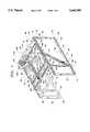
- FIG. 1is a perspective view of the instant invention numerically depicting the primary and longitudinal support structure
- FIG. 2is a duplicate of FIG. 1 with numerical depiction of the secondary support members and alignment mechanisms and providing a pictorial of a patient within the structure;
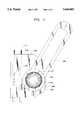
- FIG. 3is a plane view an alignment guide having a positioning protractor
- FIG. 4is a cross sectional side view of the positioning protractor of FIG. 3;
- FIG. 5is a top plane view of the horizontal alignment guide attachment to the upright support member
- FIG. 5Ais a side view of FIG. 5;
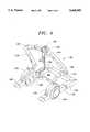
- FIG. 6is a perspective view of the upright support member.
- first lower support rail 12having a longitudinal length from a first end 14 to a second end 16.
- the lower support rail 12is parallel and spaced apart a predetermined distance in correlation to a conventional CT or X-ray scanning table to a second lower support rail 18 having a first end 20 and second end 22.
- the lower support railsinclude pegs or peg holes along the bottom thereof, not shown, for securing to a support table.
- Lower support rail 12is further defined as having an upper surface 26, inner surface 28, outer surface 30, and a lower surface 32.
- the support rail 12has a dove tail cavity 34 along the outer surface 30 of the longitudinal length of the rail which operates as a guide track.
- the dove tail cavity 34operates to position a vertical alignment target frame assembly 36 in a parallel and perpendicular position with the structure as further defined later in this specification.
- the dove tail cavitymay be replaced by any type of support surface without defeating the intent of this invention.
- An alignment slat 37fits within the guide track for precision movement.
- the second lower support rail 18is a mirror image of the first support rail 12 and has the same support surface.
- the delivery systemis raised over the body of a patient a predetermined distance by four corner legs.
- Leg 38is positioned over end 14 in a parallel planar position with a upstanding leg 40 positioned over the end 20 of the second lower support rail.
- Rear supportis provided by leg 42 located at second end 16 of the lower support rail 12 and leg 44 positioned at the second end 22 of the lower support rail 18.
- An upper structureis used to support the delivery system and is defined by a first upper support rail 48 having a longitudinal length defined by a first end 50 and a second end 52.
- a second upper support rail 54having a first end 56 and a second end 58, each upper support rail forming a mirror image thereof.
- the first upper support railis further defined by an upper surface 60, lower surface 62, inner surface 64 and outer surface 66.
- Guide track 68is disposed along the longitudinal length of the rail and operatively associated with an alignment slat 69 coupled to the vertical target frame assembly 36, the guide track maintains said target frame assembly 36 in perpendicular correlation between the upper and lower rails on each side of the device. It should be noted that any guide track shape or mechanism which maintains the target frame assembly 36 in a perpendicular manner with the upper and lower support rails is deemed within the scope of the invention.
- the upper support railsare coupled together along the first end 50 and 56 by cross support member 74 with cross support member 76 placed between second ends 52 and 58 providing rear support.
- the operation of the target frame assemblywill be explained later in this specification as it operates with a moveable structure that has not been described.
- a interface frame assembly 78defined as a substantially rectangular support having a first end 80 and a second end 82 and two parallel disposed side supports 84 and 86 each having a longitudinal length less than the longitudinal length of the first and second upper support rails 48 and 54.
- the support structure 78includes alignment slats for precision movement along the length of said upper support rails as shown by engagement brackets 88 and 92 secured to one side of the slidable support structure 78 as are brackets 94 and 96 to the opposite side, each of which operates with the dove tail type cavities 70 disposed within each said upper support rail.
- Knob 90Positioned along the first upper support rail 48 is a means for moving the interface frame such as adjustment knob 90 coupled to support rail 86 wherein rotation of the knob 90 allows precise movement of support structure along the length of said upper support rails.
- Knob 90can be coupled to a precision cut threaded rod, not shown, disposed beneath or within the upper support rail allowing the forward or reverse movement of the support structure 78.
- the engagement mechanismis preferably coated with a non-stick surface such as teflon so as to eliminate friction during movement of the structure 78.
- Arch frame assembly 98is disposed within the interface frame 78 and is defined a side rail 100 which is coupled to a second side rail 102 by first end cross connect 104 and second end cross connect 106.
- the rails and cross connectsform a rigid support platform which is slidable along the width of the interface frame 78 along end members 80 and 82, in a similar fashion as the interface frame 78 moves along the upper support.
- End cross connect 104includes a first and second bracket 108 and 110 having a means for inserting into a guide track 112 formed along an upper surface 114 of end cross connect 80.
- brackets 116 and 118are operatively associated with an upper surface of end cross support 82 each having alignment slats operatively associated with the tracks.
- the arch frame assembly 98includes an adjustment mechanism 122 which engages the interface frame allowing the operator to precisely move the arch frame assembly 98 along the width of the interface frame assembly 78.
- side rails 100 and 102includes a circular shaped support bracket 128 and 130 for receipt of an arch frame defined by an arc 136 having a lower member 144 which is pivotally coupled to the support bracket 130 by use of removable tab inserts, not shown.
- the removable tab insertsallow the operator to insert a variety of delivery frame assemblies from various manufacturers into the arch frame assembly. For instance, a surgeon who is familiar with the delivery frame assembly used with head surgery would be more receptive to using that delivery system which can be positioned within the arch frame.
- the circular shaped support bracketsallow rotation of the arc 136 allowing the angle of rotation to be read along frame marking indicia 132 and alignment pointer 134.
- the lower members 144 and 148lead to an angularly shaped inverted curved measurement bar 146.
- the measurement support 146further sets forth adjustment angle positioning by viewing of the measurement indicia 152 providing exacting positioning of the delivery assembly 154.
- the delivery assembly 154is defined as a substantially flat bar constructed of a transparent material coupled to the arc 136 by sleeve 160 and locking mechanism 162.
- the delivery assembly 154can be removed without changing of the arch.
- a typical delivery assemblywill include holding bracket's 164 and 166 for coupling syringes, cannulas, guide wires and the like medical devices.
- an attachment point 200is provide for engaging of an alignment wire for position of the arc 136.
- the attachment point 200is secured to each side surface of the frame assembly 100 and 102, preferably along a portion of the circular support so as to raise the attachment point over the surface of the device for proper clearance.
- the delivery systemWhen the device is placed over a patient 199 as depicted in FIG. 2, the delivery system is positionable by movement of the arc 136 in a forward or backward direction viewable along rotational brackets 128 and 130.
- the delivery system 154can be moved from side to side and the arch frame assembly 98 positioned along a longitudinal length of the device by movement of interface frame assembly 78.
- Target frame assembly 36is a unique alignment device that provides infinite repeatability by use of two identical target assemblies defined as sighting tubes 168 and 190.
- the first upright leg 170 of the target frame assembly 36has a lower end 172 operatively associated with the lower support rail 12 and having a longitudinal length extending a second end 174 above the surface of the upper support rail 48.
- a portion 175 of said upright 170includes a means for attaching to a side surface of said upper support rail 48 wherein movement of said leg 170 is maintained in a perpendicular format to said upper and lower support rails.
- a slot 176formed along a section thereof for placement of said target assembly 168.
- the target assembly 168includes a protractor 182 disposed around a through hole 184 that operates to set forth an angle when used in conjunction with stirrup 186.
- a free end of said stirrup 186is coupled to the slidable support structure 78 by side stirrup connector 188 which extends above the surface of said first upper side rail 48 and secured to the upper surface 86 of said slidable support structure 78.
- the stirrup 186changes angles and the angle can be read by protractor surface 182 along alignment marker 187.
- the vertical position of the target assembly 168can be moved wherein the height can be recorded through a transparent support housing 189 having markings 191 on the upright.
- the target assembly 168includes throughhole 184 having internally disposed cross hair hatching 193, shown in FIG. 3 wherein a real time X-ray therethrough would allow the surgeon to align the device to an internal body structure.
- a scan or X-ray of the bodycan be performed through the cross hatching 193 of the target assembly 168 wherein positioning thereof can be read by the protractor 182.
- the slidable support structure 78can be located over a portion of the body to be operated upon for direct placement of the delivery system.
- Upper alignment guide 190is positioned along the horizontal cross brace 180 having stirrup 200 providing a direct correlation to the arc 136 by cross member 222 as further shown in FIGS. 5 and 5A.
- the alignment guide 190can be slid along the cross brace through slot 194 in correlation with the movement of arch frame assembly 98.
- the protractor guide and target assembly used on the vertical alignment guide and horizontal target frame assembly alignment guideare identical and thus only the vertical guide is described by separate illustration.
- each guideconsists of a protractor 182 having numerical indicia positioned along a surface of the protractor.
- the stirrup 186is coupled to stirrup coupler 188 which is slidably securable to the target assembly by placement within the alignment marker 187 which further operates as a spacer, see FIG. 4.
- the stirrup 186is held in position by lock nut 191 as the protractor 182 is placed on the end of a securement bolt 193.
- the transparent support housing 189is slidably secured to the upright leg 170 by coupling brackets 195.
- Movement of the interface frametranslates to movement of the stirrup 186 which slides along the length of the target assembly 168.
- the indiciais read along surface 182 with parallel alignment marker 187.
- Shown in the illustrationis the stirrup at a thirty degree angle.
- the guidelinesare disposed around the outer surface of the protractor providing ease of alignment and verification of angles.
- the cross-hairs 193used with an active X-ray or radio X-ray allowing the surgeon to precisely point the alignment guide to a portion of the patient's body providing a baseline or alignment point from which all adjustments can be ascertained.
- stirrup 186is rotatably coupled to side stirrup connector 188.
- the horizontal alignment guide 190uses stirrup 200 with a point of attachment 225 by a pinion guide inserted into cross member 222.
- the method of targeting and deliverycan be followed from the steps of: positioning a base support frame over the body of a patient placed upon a support table; inserting an interface frame onto said system frame; placing an arch assembly onto said interface frame; coupling a targeting frame assembly to said system frame with stirrups coordinating said targeting frame to said interface frame and said arch assembly; attaching a delivery bracket to said arch frame assembly; means for aligning said delivery bracket to a predetermined position by setting an angle of lateral and longitudinal entry.
- the means for aligningincludes the steps of: sliding said target frame along said base system frame to a desired location and locking in position so as to set the X coordinate; sliding said side mounted target assembly along said target frame to a desired location and locking said side target assembly in position providing coordinate Y; and sliding said top target assembly along said target frame to a desired location and locking in position for providing a coordinate Z.
- the method of setting an angle of lateral entrycomprises the steps of: sliding said interface along said base system frame until side stirrup aligns with a desired angle wherein said slide interface frame is locked in position; and adjusting a desired angle of the arch rotator with arch frame to match angle side stirrup and lock in position.
- the method of setting an angle of longitudinal entrycomprises the steps of: sliding said arch frame along said interface frame until said top stirrup aligns with a desired angle wherein said arch frame is locked in position; and sliding said delivery system along said arch assembly to match angle of said top stirrup wherein said delivery system is locked into position.
Landscapes
- Health & Medical Sciences (AREA)
- Surgery (AREA)
- Life Sciences & Earth Sciences (AREA)
- Heart & Thoracic Surgery (AREA)
- Pathology (AREA)
- Oral & Maxillofacial Surgery (AREA)
- Engineering & Computer Science (AREA)
- Biomedical Technology (AREA)
- Nuclear Medicine, Radiotherapy & Molecular Imaging (AREA)
- Medical Informatics (AREA)
- Molecular Biology (AREA)
- Animal Behavior & Ethology (AREA)
- General Health & Medical Sciences (AREA)
- Public Health (AREA)
- Veterinary Medicine (AREA)
- Apparatus For Radiation Diagnosis (AREA)
Abstract
Description
This invention relates to stereotactic devices and more particularly to a guidance device capable of precision orientation of surgical devices in a three-dimensional plane.
Guidance devices are well known in the art for use with X-ray or scanning devices providing a surgeon with multi-dimensional viewing of the skeletal and supporting structure wherein various medical procedures on the body can be performed. Such devices provide a stability to a surgical instrument not possible by human hands and in many instances allow hands free operation. Typically the guidance device is set upon a structure used in combination with a scan table. The structure can be moved yet maintain a level position despite vertical or horizontal disposition. Bracketry is available to support items such as a needle. A protractor may be used to determine the desired plane, the rotation of which is set to match angulation of a target path as determined by a scan.
The CT scan allows the determination of the ultimate target path so as to avoid penetration of vital structures such as nerves or vessels thereby minimizing both the time of surgery and the extent thereof. Common to prior art devices is their targeting limitations.
Prior art discloses a number of stereotactic devices which are dependent upon the diagnostic mapping of a patient such as those generated by a multi-plane scanner for use in locating an internal region of interest in advance of a clinical procedure.
Variations of stereotactic devices include a means for rotating a probe holder in a vertical or horizontal plane using protractors to verify finite movement in length or angle. The aiming of the probe is accomplished by use of a CT scan providing coordinates of a presumed target within the body. A scan can be made and the aim of the medical device verified by superimposing the target on a scanner printout. When a guide is accurately aimed both in the coronal and sagittal planes, a medical instrument can be inserted into the body at the proper depth, the position verified by a CT scan or roentgenogram.
Stereotactic devices are unique in that they are adaptable to align and orientate a variety of medical instruments such as guide wires, needles, and cannulas into the human body so as to perform such procedures as percutaneous dissectomies, cysts, aspirations, tumor localizations, biopsies and the like type operations.
U.S. Pat. No. 4,791,934 discloses a clinical method in positioning a surgical instrument by first imaging a patient so as to produce a three-dimensional diagnostic mapping data, transferring the patient to a treatment station by generating a dimensional calibration reference image through the patient followed by configuring an analogous two-dimensional image from the three-dimensional diagnostic mapping data. The calibration reference and diagnostic data of the images are then determined to place the relative orientation between the patient and the three-dimensional mapping data so as to orient the surgical instrument in a precise position relative to the patient for treatment of the structure.
U.S. Pat. No. 5,308,352 discloses a stereotactic device which is adapted for use with a scanner when a patient is placed upon the surface of a CT scan table. The device consists of a carrier for a medical device which is placed on a horizontal bridge supported by two vertical legs that are slidably adjustable along the horizontal length of the scan table with a means for locking thereto. The limitation to the instant invention is most notable on the rotation of the carrier mechanism relative to the vertical legs. The radial rotation of the medical device is limited in its holding of the device that would be inserted into the body due to the fixed position of the vertical legs. With such technology the surgeon can accurately place biopsy needles in drainage catheters within a body carefully avoiding critical areas such as nerves, veins, and muscle that may adversely affect the patient.
U.S. Pat. No. 5,047,036 discloses a stereotactic guidance device consisting of a stainless steel bridge which spans a scanner table and is either mounted directly to the table or mounted on two anchored vertical side rails permanently mounted to the floor.
Thus, what is needed in the art is a portable, true stereotactic guiding mechanism for medical devices may work in conjunction with an X-ray or CT scanner so as to accurately position a surgical instrument in a three-dimensional plane so as to allow a surgical operation on a patient with minimal setup time or exploratory disruption to the body.
The instant invention operates to provide a surgeon with a portable stereotactic guidance device for precisely orientating medical devices such as needles, cannulas and guide wires. The device consists of a portable support structure which is placed upon a CT scanning or X-ray table either before or after the placement of a patient. Vertical legs are disposed on each side of the patient and a cross connect forming a base support structure maintains the legs in a stationary position. Along a top surface of the support structure is an interface frame assembly which can move along the longitudinal length of the base structure. A guide track with matching alignment slats having precise tolerances is operatively associated with each support structure to eliminate lateral movement. A handwheel provides precision adjustment of the interface frame assembly along the longitudinal length of the base support structure.
A arch frame assembly is placed within the interface frame assembly and operates to move along the width of said interface frame assembly. The interface frame assembly includes a guide track with matching alignment slats attached to the arch frame assembly, which allows movement of the arch frame from side to side within the confines of the interface frame assembly. A hand wheel provides adjustment in its movement along the width of the interface frame assembly. The arch frame assembly operates to hold an upright structure capable of articulating approximately 45 degrees in a forward and reverse position and operates to secure a transparent holding bracket that tilts from left to right. The holding bracket rotates along a pivot point approximately thirty degrees from a normally perpendicular stance.
An alignment target frame assembly is incorporated into the aforementioned structure formed from two vertical legs having a cross connect external the base structure and extending slightly above the surface of the movable support structures. Along one vertical leg of the target frame assembly is a sight hole having a circular viewing port with cross hatches that allow the surgeon to scan through the port and line up the device with a portion of the patient's body. An angle can be determined in relation to the longitudinal support structure by reference to a guide wire connected between the viewing and secondary support structure wherein the angle can be read on a protractor face disposed about the surface of the port. The vertical side rails are movable along the length of the primary support structure by use of a hand wheel providing precision movements so as to permit repositioning of the device upon angular adjustment.
In operation, a scan of a patient can be made wherein the device can be set according to the patient's body. All measurements are taken in a three-dimensional format so as to allow the surgeon to repeat placement of the alignment device when the actual surgery is to be performed. The device can be adjusted to the previously aligned patient's body position wherein each support structure is adjusted to the previously depicted measurement location so as to set forth a probe holder in the exact position as previously planned so as to lessen surgery time. The surgeon may begin an operation and verify the process by real time scanning.
Once a target is set, the delivery system is aligned by sliding the delivery system within a cartesian coordinate system thereby rotating the stirrups along a polar coordinate system. The delivery system can be aligned by rotation of the stirrups to either specified angels or desired images. The delivery system can be used independently from the targeting system. For example the placement of a pedicle screw may be performed by set angle ∝ at 10 degrees, vary angle .o slashed. to match measured angle of vertebrae from X-ray, then sliding interface frame and arch frame to a desired position.
Thus, an objective of the invention is to provide a stereotactic guidance device capable of three-dimensional plane adjustment.
Still another objective of the invention is to teach a method of targeting and delivery of surgical devices that can be used with computer guided equipment such as robotic arms.
Another objective of the instant invention is to provide a portable guidance device that allows a surgeon to place a surgical instrument in a secure hands free position.
Still another objective of the instant invention is to provide a stereotactic guidance device that operates in a real time mode with an X-ray or scanner.
Yet another objective of the instant invention is to provide a separate alignment target frame assembly which operates in conjunction with one of the support structures so as to provide a cross-sectional displacement of the apparatus in combination with an angular disposition a primary carrier structure.
Still another objective of the instant invention is provide a stereotactic targeting and delivery systems that can be used with other wands, frameless, stereotactic arc's such as robotic arms.
Other objectives and advantages of this invention will become apparent from the following description taken in conjunction with the accompanying drawings wherein are set forth, by way of illustration and example, certain embodiments of this invention. The drawings constitute a part of this specification and include exemplary embodiments of the present invention and illustrate various objectives and features thereof.
FIG. 1 is a perspective view of the instant invention numerically depicting the primary and longitudinal support structure; and
FIG. 2 is a duplicate of FIG. 1 with numerical depiction of the secondary support members and alignment mechanisms and providing a pictorial of a patient within the structure;
FIG. 3 is a plane view an alignment guide having a positioning protractor;
FIG. 4 is a cross sectional side view of the positioning protractor of FIG. 3;
FIG. 5 is a top plane view of the horizontal alignment guide attachment to the upright support member;
FIG. 5A is a side view of FIG. 5; and
FIG. 6 is a perspective view of the upright support member.
Although the invention has been described in terms of a specific embodiment, it will be readily apparent to those skilled in this art that various modifications, rearrangements and substitutions can be made without departing from the spirit of the invention. The scope of the invention is defined by the claims appended hereto.
Now referring in general to FIGS. 1 and 2, shown is the instant invention with a firstlower support rail 12 having a longitudinal length from afirst end 14 to asecond end 16. Thelower support rail 12 is parallel and spaced apart a predetermined distance in correlation to a conventional CT or X-ray scanning table to a secondlower support rail 18 having afirst end 20 andsecond end 22. The lower support rails include pegs or peg holes along the bottom thereof, not shown, for securing to a support table.Lower support rail 12 is further defined as having anupper surface 26,inner surface 28,outer surface 30, and alower surface 32. Thesupport rail 12 has adove tail cavity 34 along theouter surface 30 of the longitudinal length of the rail which operates as a guide track. As will be described later in this specification, thedove tail cavity 34 operates to position a vertical alignmenttarget frame assembly 36 in a parallel and perpendicular position with the structure as further defined later in this specification. The dove tail cavity may be replaced by any type of support surface without defeating the intent of this invention. Analignment slat 37 fits within the guide track for precision movement. The secondlower support rail 18 is a mirror image of thefirst support rail 12 and has the same support surface.
The delivery system is raised over the body of a patient a predetermined distance by four corner legs.Leg 38 is positioned overend 14 in a parallel planar position with aupstanding leg 40 positioned over theend 20 of the second lower support rail. Rear support is provided byleg 42 located atsecond end 16 of thelower support rail 12 andleg 44 positioned at thesecond end 22 of thelower support rail 18. An upper structure is used to support the delivery system and is defined by a firstupper support rail 48 having a longitudinal length defined by afirst end 50 and asecond end 52. A secondupper support rail 54 having afirst end 56 and asecond end 58, each upper support rail forming a mirror image thereof. The first upper support rail is further defined by anupper surface 60,lower surface 62,inner surface 64 andouter surface 66.Guide track 68 is disposed along the longitudinal length of the rail and operatively associated with analignment slat 69 coupled to the verticaltarget frame assembly 36, the guide track maintains saidtarget frame assembly 36 in perpendicular correlation between the upper and lower rails on each side of the device. It should be noted that any guide track shape or mechanism which maintains thetarget frame assembly 36 in a perpendicular manner with the upper and lower support rails is deemed within the scope of the invention.
The upper support rails are coupled together along thefirst end cross support member 74 withcross support member 76 placed between second ends 52 and 58 providing rear support. The operation of the target frame assembly will be explained later in this specification as it operates with a moveable structure that has not been described.
Within the upper support rails 48 and 54 is positioned ainterface frame assembly 78 defined as a substantially rectangular support having afirst end 80 and asecond end 82 and two parallel disposed side supports 84 and 86 each having a longitudinal length less than the longitudinal length of the first and second upper support rails 48 and 54. Thesupport structure 78 includes alignment slats for precision movement along the length of said upper support rails as shown byengagement brackets slidable support structure 78 as arebrackets tail type cavities 70 disposed within each said upper support rail. Positioned along the firstupper support rail 48 is a means for moving the interface frame such asadjustment knob 90 coupled to supportrail 86 wherein rotation of theknob 90 allows precise movement of support structure along the length of said upper support rails.Knob 90 can be coupled to a precision cut threaded rod, not shown, disposed beneath or within the upper support rail allowing the forward or reverse movement of thesupport structure 78. The engagement mechanism is preferably coated with a non-stick surface such as teflon so as to eliminate friction during movement of thestructure 78.
As further illustrated by FIG. 6, side rails 100 and 102 includes a circular shapedsupport bracket arc 136 having alower member 144 which is pivotally coupled to thesupport bracket 130 by use of removable tab inserts, not shown. The removable tab inserts allow the operator to insert a variety of delivery frame assemblies from various manufacturers into the arch frame assembly. For instance, a surgeon who is familiar with the delivery frame assembly used with head surgery would be more receptive to using that delivery system which can be positioned within the arch frame. The circular shaped support brackets allow rotation of thearc 136 allowing the angle of rotation to be read alongframe marking indicia 132 andalignment pointer 134. Thelower members curved measurement bar 146. Themeasurement support 146 further sets forth adjustment angle positioning by viewing of themeasurement indicia 152 providing exacting positioning of thedelivery assembly 154. Thedelivery assembly 154 is defined as a substantially flat bar constructed of a transparent material coupled to thearc 136 bysleeve 160 andlocking mechanism 162. Thedelivery assembly 154 can be removed without changing of the arch. A typical delivery assembly will include holding bracket's 164 and 166 for coupling syringes, cannulas, guide wires and the like medical devices.
As described in detail later in the specification, anattachment point 200 is provide for engaging of an alignment wire for position of thearc 136. Theattachment point 200 is secured to each side surface of theframe assembly
When the device is placed over apatient 199 as depicted in FIG. 2, the delivery system is positionable by movement of thearc 136 in a forward or backward direction viewable alongrotational brackets delivery system 154 can be moved from side to side and thearch frame assembly 98 positioned along a longitudinal length of the device by movement ofinterface frame assembly 78.
Movement of the interface frame translates to movement of thestirrup 186 which slides along the length of thetarget assembly 168. As the stirrup is positioned in an offset position, the indicia is read alongsurface 182 withparallel alignment marker 187. Shown in the illustration is the stirrup at a thirty degree angle. The guidelines are disposed around the outer surface of the protractor providing ease of alignment and verification of angles. In the middle of thetarget assembly 168 is shown the cross-hairs 193 used with an active X-ray or radio X-ray allowing the surgeon to precisely point the alignment guide to a portion of the patient's body providing a baseline or alignment point from which all adjustments can be ascertained.
It should be noted that the alignment wire protractor surface and adjustment slot depicted in the vertical alignment guide is identical to the horizontal alignment guide except for the point of attachment. In the vertical alignment guide,stirrup 186 is rotatably coupled toside stirrup connector 188. Thehorizontal alignment guide 190 usesstirrup 200 with a point ofattachment 225 by a pinion guide inserted intocross member 222.
While what has been described is a mechanical system, it will be obvious to one skilled in the art that the teaching herein is of a method of targeting and delivery of surgical devices. Use of this teaching will allow one skilled in the art to incorporate the teachings into various embodiments including computer software programming for robotic delivery. In accordance with this teaching, the method of targeting and delivery can be followed from the steps of: positioning a base support frame over the body of a patient placed upon a support table; inserting an interface frame onto said system frame; placing an arch assembly onto said interface frame; coupling a targeting frame assembly to said system frame with stirrups coordinating said targeting frame to said interface frame and said arch assembly; attaching a delivery bracket to said arch frame assembly; means for aligning said delivery bracket to a predetermined position by setting an angle of lateral and longitudinal entry.
The means for aligning includes the steps of: sliding said target frame along said base system frame to a desired location and locking in position so as to set the X coordinate; sliding said side mounted target assembly along said target frame to a desired location and locking said side target assembly in position providing coordinate Y; and sliding said top target assembly along said target frame to a desired location and locking in position for providing a coordinate Z.
The method of setting an angle of lateral entry comprises the steps of: sliding said interface along said base system frame until side stirrup aligns with a desired angle wherein said slide interface frame is locked in position; and adjusting a desired angle of the arch rotator with arch frame to match angle side stirrup and lock in position.
The method of setting an angle of longitudinal entry comprises the steps of: sliding said arch frame along said interface frame until said top stirrup aligns with a desired angle wherein said arch frame is locked in position; and sliding said delivery system along said arch assembly to match angle of said top stirrup wherein said delivery system is locked into position.
It is to be understood that while I have illustrated and described certain forms of my invention, it is not to be limited to the specific forms or arrangement of parts herein described and shown. It will be apparent to those skilled in the art that various changes may be made without departing from the scope of the invention and the invention is not to be considered limited to what is shown in the drawings and described in the specification.
Claims (24)
1. A surgery guidance device comprising:
a base for securing to a table, said base forming an adjustable guidance carrier for positioning over a patient's body characterized by two horizontally disposed spaced apart rigid lower support members each having a length with a first end and a second end, said lower support members having upwardly facing support legs positioned perpendicular thereto coupling horizontally disposed spaced apart rigid upper support members placed in a parallel plane to said lower support members, each upper support member having a length with a first end and a second end attached to said support legs, each upper and lower support member as joined by said support legs forming a side member assembly, and each end of each upper support member having a cross brace member disposed therebetween;
an interface frame assembly slidably disposed within said upper support members, said frame having an upper surface and a width and a length less than a length of said base, said upper surface of said interface frame assembly including at least one side rail crossing said width of said interface frame assembly, each said side rail having a guide track on its upper surface;
an arch frame assembly slidably disposed within said interface frame assembly having a width and a length, said arch frame assembly width less than said width of said interface frame assembly; an alignment slat secured to said arch frame assembly with said guide track operatively associated with said alignment slat; an arc member pivotally coupled to said arch frame assembly; means for tilting said arc member; and a delivery system pivotally coupled to said arc member.
2. The guidance device according to claim 1 wherein an upper surface of each said upper support member includes a guide track disposed between said first end and said second end operatively associated with an alignment slat secured to said interface frame assembly.
3. The guidance device according to claim 1 including a means for moving said interface frame assembly along said length of said upper support members.
4. The guidance device according to claim 1 wherein said interface frame assembly includes a position determining means in relation to said base support.
5. The guidance device according to claim 1 including a means for moving said arch frame assembly along said width of said interface frame assembly.
6. The guidance device according to claim 1 wherein said arch frame assembly includes measurement indicia for positioning in relation to said interface frame assembly.
7. The guidance device according to claim 1 wherein said arch frame assembly includes a circular shaped receptacle along each side support rail for rotatable receipt of said arc member, said receptacle having measurement indicia placed along a side surface to assist in angular positioning of said arc member.
8. The guidance device according to claim 7 wherein said receptacle includes a means for securing said arc member in a fixed position.
9. The guidance device according to claim 1 including an alignment target frame assembly defined by two vertically disposed legs slidable along the longitudinal length of each said side member assembly and connected by a horizontally disposed cross connect set a predetermined distance above said base support member.
10. The guidance device according to claim 9 wherein said alignment target frame assembly includes at least one targeting device having a means for real time positioning and a means for determination of angular positioning to said interface frame.
11. The guidance device according to claim 10 wherein said means for real time positioning is further defined as a sight tube having cross-hairs for imaging therethrough.
12. The guidance device according to claim 10 wherein determination of angular positioning is performed by reading of angular degree indicia positioned along the circumference of a securement bolt having an alignment marker maintained in a parallel position to a stirrup wire coupled to said interface frame.
13. The guidance device according to claim 10 wherein said means for real time positioning is further defined as a sight tube having cross-hairs for imaging therethrough.
14. The guidance device according to claim 10 wherein determination of angular positioning is performed by reading of angular degree indicia positioned along the circumference of a securement bolt having an alignment marker maintained in a parallel position to a stirrup wire coupled to said arch frame assembly.
15. The guidance device according to claim 1 wherein said delivery system is constructed from transparent material with at least one bracket available for releasably coupling a surgical tool.
16. The guidance device according to claim 1 wherein including a means for locking said delivery system to said arc member having positioning indicia disposed on said arc member.
17. A surgery guidance device for use in combination with a X-Ray or CT scanner comprising:
a base defined by two horizontally disposed spaced apart rigid lower support members each having a length with a first end and a second end with upwardly facing support legs positioned perpendicular thereto coupling horizontally disposed spaced apart rigid upper support members placed in a parallel plane to said lower support member, each upper support member having a length with a first end and a second And attached to said support legs, and each end of each upper support member having a cross brace member disposed therebetween;
a interface frame assembly slidably disposed within said upper support members, said interface frame having a width and a length less than a length of said base support member;
a means for moving said interface frame assembly along a length of said base;
an arch frame assembly slidably disposed within said interface frame assembly having a width and a length, said arch frame assembly width less than said width of said interface frame assembly;
a means for moving said arch frame assembly along a width of said interface frame;
an arc member coupled to said arch frame assembly defined as a substantially inverted U-shaped housing pivotable along said width of said arch frame assembly;
means for tilting said arc member, said means for tilting including a means for securing said arc member in an angular position;
a delivery system pivotally coupled to said arch member;
an alignment target frame assembly defined by at least one vertically disposed leg slidable along the longitudinal length of one said side member coupled to said interface frame assembly; and
a means for securing said base to an X-Ray or scanning table.
18. The guidance device according to claim 17 wherein said alignment target frame assembly includes a positioning bracket slidable along a vertical length of said first leg.
19. The guidance device according to claim 18 wherein said positioning bracket includes a through hole having a centrally disposed positioning marker and exterior angular indicia marking.
20. The guidance device according to claim 17 wherein said side member is coupled to said interface frame assembly by a rigid rod having a first end rotatably coupled to a positioning bracket and a free end slidably attached to said interface frame assembly, said rigid rod angular displacement read against exterior angular indicia marking.
21. A method of targeting and delivery of surgical devices said method comprising:
positioning a base support frame over the body of a patient placed upon a support table;
inserting an interface frame onto said system frame;
placing an arch assembly onto said interface frame;
coupling a targeting frame assembly to said system frame with stirrups coordinating said targeting frame to said interface frame and said arch assembly;
attaching a delivery bracket to said arch frame assembly;
means for aligning said delivery bracket to a predetermined position by setting an angle of lateral and longitudinal entry.
22. The method of targeting according to claim 21 wherein said means for aligning includes the steps of:
sliding said target frame along said base system frame to a desired location and locking in position so as to set the X coordinate;
sliding said side mounted target assembly along said target frame to a desired location and locking said side target assembly in position providing coordinate Y; and
sliding said top target assembly along said target frame to a desired location and locking in position for providing a coordinate Z.
23. The method of targeting according to claim 21 wherein said setting of an angle of lateral entry comprises the steps of:
sliding said interface along said base system frame until side stirrup aligns with a desired angle wherein said slide interface frame is locked in position; and
adjusting a desired angle of the arch rotator with arch frame to match angle side stirrup and lock in position.
24. The method of targeting according to claim 21 wherein said setting of an angle of longitudinal entry comprises the steps of:
sliding said arch frame along said interface frame until said top stirrup aligns with a desired angle wherein said arch frame is locked in position; and
sliding said delivery system along said arch assembly to match angle of said top stirrup wherein said delivery system is locked into position.
Priority Applications (1)
| Application Number | Priority Date | Filing Date | Title |
|---|---|---|---|
| US08/356,517US5665095A (en) | 1994-12-15 | 1994-12-15 | Stereotactic guidance device |
Applications Claiming Priority (1)
| Application Number | Priority Date | Filing Date | Title |
|---|---|---|---|
| US08/356,517US5665095A (en) | 1994-12-15 | 1994-12-15 | Stereotactic guidance device |
Publications (1)
| Publication Number | Publication Date |
|---|---|
| US5665095Atrue US5665095A (en) | 1997-09-09 |
Family
ID=23401766
Family Applications (1)
| Application Number | Title | Priority Date | Filing Date |
|---|---|---|---|
| US08/356,517Expired - Fee RelatedUS5665095A (en) | 1994-12-15 | 1994-12-15 | Stereotactic guidance device |
Country Status (1)
| Country | Link |
|---|---|
| US (1) | US5665095A (en) |
Cited By (66)
| Publication number | Priority date | Publication date | Assignee | Title |
|---|---|---|---|---|
| WO2000017751A1 (en)* | 1998-09-22 | 2000-03-30 | Intel Corporation | Method for combining the computer models of two surfaces in 3-d space |
| US6045558A (en)* | 1995-08-14 | 2000-04-04 | Deutsches Krebsforschungszentrum Stiftung Des Offentlichen Rechts | Whole body stereotaxic device |
| WO2000064354A3 (en)* | 1999-04-26 | 2001-03-08 | Scimed Life Systems Inc | Apparatus and methods for guiding a needle |
| US6221082B1 (en) | 1998-06-09 | 2001-04-24 | Nuvasive, Inc. | Spinal surgery guidance platform |
| US6273896B1 (en) | 1998-04-21 | 2001-08-14 | Neutar, Llc | Removable frames for stereotactic localization |
| US6282437B1 (en) | 1998-08-12 | 2001-08-28 | Neutar, Llc | Body-mounted sensing system for stereotactic surgery |
| US6298262B1 (en) | 1998-04-21 | 2001-10-02 | Neutar, Llc | Instrument guidance for stereotactic surgery |
| US20020007188A1 (en)* | 2000-06-22 | 2002-01-17 | Jared Arambula | Polar coordinate surgical guideframe |
| US6351662B1 (en) | 1998-08-12 | 2002-02-26 | Neutar L.L.C. | Movable arm locator for stereotactic surgery |
| US6529765B1 (en) | 1998-04-21 | 2003-03-04 | Neutar L.L.C. | Instrumented and actuated guidance fixture for sterotactic surgery |
| US6546277B1 (en) | 1998-04-21 | 2003-04-08 | Neutar L.L.C. | Instrument guidance system for spinal and other surgery |
| US20030114862A1 (en)* | 2001-12-14 | 2003-06-19 | Chu Michael S.H. | Methods and apparatus for guiding a needle |
| US6689142B1 (en) | 1999-04-26 | 2004-02-10 | Scimed Life Systems, Inc. | Apparatus and methods for guiding a needle |
| US20050053192A1 (en)* | 2003-08-07 | 2005-03-10 | Predrag Sukovic | Intraoperative stereo imaging system |
| US20050216026A1 (en)* | 2004-01-14 | 2005-09-29 | Culbert Brad S | Guidance system for spinal stabilization |
| US20050273167A1 (en)* | 2004-06-02 | 2005-12-08 | Triplett Daniel J | Surgical measurement and resection framework |
| USD550348S1 (en) | 2004-09-30 | 2007-09-04 | Integra Radionics, Inc. | Stereotactic head frame localizer |
| US20080154198A1 (en)* | 2008-02-05 | 2008-06-26 | Deye Wei | Needle insertion assistance device |
| US20090198309A1 (en)* | 2007-07-18 | 2009-08-06 | Visualase, Inc. | Systems and methods for thermal therapy |
| WO2010021951A2 (en) | 2008-08-18 | 2010-02-25 | The Brigham And Women's Hospital, Inc. | Integrated surgical sampling probe |
| US20110118593A1 (en)* | 2000-03-01 | 2011-05-19 | Medtronic Navigation, Inc. | Multiple Cannula Image Guided Tool for Image Guided Procedures |
| US20140249546A1 (en)* | 2011-11-30 | 2014-09-04 | Titan Medical Inc. | Apparatus and method for supporting a robotic arm |
| FR3019983A1 (en)* | 2014-04-22 | 2015-10-23 | Iin Medical | EXOCENTRIC SURGICAL DEVICE |
| US20160166324A1 (en)* | 2014-12-12 | 2016-06-16 | Elekta Ab (Publ) | Stereotactic surgical instrument |
| US9522070B2 (en) | 2013-03-07 | 2016-12-20 | Interventional Spine, Inc. | Intervertebral implant |
| US20160367766A1 (en)* | 2015-03-24 | 2016-12-22 | Jeff Baker | Injection training and compliance device and method |
| US9707049B1 (en)* | 2016-12-22 | 2017-07-18 | The Florida International University Board Of Trustees | Stereotactic device for implantation of permanent implants into a rodent brain |
| US9839530B2 (en) | 2007-06-26 | 2017-12-12 | DePuy Synthes Products, Inc. | Highly lordosed fusion cage |
| US9883951B2 (en) | 2012-08-30 | 2018-02-06 | Interventional Spine, Inc. | Artificial disc |
| US9895236B2 (en) | 2010-06-24 | 2018-02-20 | DePuy Synthes Products, Inc. | Enhanced cage insertion assembly |
| US9913727B2 (en) | 2015-07-02 | 2018-03-13 | Medos International Sarl | Expandable implant |
| US9931223B2 (en) | 2008-04-05 | 2018-04-03 | DePuy Synthes Products, Inc. | Expandable intervertebral implant |
| US9993349B2 (en) | 2002-06-27 | 2018-06-12 | DePuy Synthes Products, Inc. | Intervertebral disc |
| US10058433B2 (en) | 2012-07-26 | 2018-08-28 | DePuy Synthes Products, Inc. | Expandable implant |
| US10143810B2 (en)* | 2016-03-22 | 2018-12-04 | Muhammad Zubair Saeed Malik | Needle guide |
| US10251722B1 (en) | 2018-09-17 | 2019-04-09 | The Florida International University Board Of Trustees | Stereotaxic brain implant system for large animals |
| US10390963B2 (en) | 2006-12-07 | 2019-08-27 | DePuy Synthes Products, Inc. | Intervertebral implant |
| US10398563B2 (en) | 2017-05-08 | 2019-09-03 | Medos International Sarl | Expandable cage |
| US10433977B2 (en) | 2008-01-17 | 2019-10-08 | DePuy Synthes Products, Inc. | Expandable intervertebral implant and associated method of manufacturing the same |
| US10471607B2 (en) | 2011-11-04 | 2019-11-12 | Titan Medical Inc. | Apparatus and method for controlling an end-effector assembly |
| US10500062B2 (en) | 2009-12-10 | 2019-12-10 | DePuy Synthes Products, Inc. | Bellows-like expandable interbody fusion cage |
| US10537436B2 (en) | 2016-11-01 | 2020-01-21 | DePuy Synthes Products, Inc. | Curved expandable cage |
| US10548741B2 (en) | 2010-06-29 | 2020-02-04 | DePuy Synthes Products, Inc. | Distractible intervertebral implant |
| US10869721B2 (en) | 2003-11-07 | 2020-12-22 | Visualase, Inc. | Cooled laser fiber and method for improved thermal therapy |
| US10888433B2 (en) | 2016-12-14 | 2021-01-12 | DePuy Synthes Products, Inc. | Intervertebral implant inserter and related methods |
| US10940016B2 (en) | 2017-07-05 | 2021-03-09 | Medos International Sarl | Expandable intervertebral fusion cage |
| US11172821B2 (en) | 2016-04-28 | 2021-11-16 | Medtronic Navigation, Inc. | Navigation and local thermometry |
| US11259891B2 (en) | 2011-09-16 | 2022-03-01 | Hologic, Inc. | Breast biopsy lateral arm system |
| US11284869B2 (en)* | 2011-09-16 | 2022-03-29 | Hologic, Inc. | Breast biopsy lateral arm system |
| WO2022069891A3 (en)* | 2020-10-02 | 2022-05-19 | Cmr Surgical Limited | Surgical robot calibration device |
| US11344424B2 (en) | 2017-06-14 | 2022-05-31 | Medos International Sarl | Expandable intervertebral implant and related methods |
| US11426290B2 (en) | 2015-03-06 | 2022-08-30 | DePuy Synthes Products, Inc. | Expandable intervertebral implant, system, kit and method |
| US11426286B2 (en) | 2020-03-06 | 2022-08-30 | Eit Emerging Implant Technologies Gmbh | Expandable intervertebral implant |
| US11446156B2 (en) | 2018-10-25 | 2022-09-20 | Medos International Sarl | Expandable intervertebral implant, inserter instrument, and related methods |
| US11452607B2 (en) | 2010-10-11 | 2022-09-27 | DePuy Synthes Products, Inc. | Expandable interspinous process spacer implant |
| US11510788B2 (en) | 2016-06-28 | 2022-11-29 | Eit Emerging Implant Technologies Gmbh | Expandable, angularly adjustable intervertebral cages |
| US11596522B2 (en) | 2016-06-28 | 2023-03-07 | Eit Emerging Implant Technologies Gmbh | Expandable and angularly adjustable intervertebral cages with articulating joint |
| US11612491B2 (en) | 2009-03-30 | 2023-03-28 | DePuy Synthes Products, Inc. | Zero profile spinal fusion cage |
| US11752009B2 (en) | 2021-04-06 | 2023-09-12 | Medos International Sarl | Expandable intervertebral fusion cage |
| US11789099B2 (en)* | 2018-08-20 | 2023-10-17 | Children's Hospital Medical Center | System and method for guiding an invasive device |
| US11850160B2 (en) | 2021-03-26 | 2023-12-26 | Medos International Sarl | Expandable lordotic intervertebral fusion cage |
| US11911287B2 (en) | 2010-06-24 | 2024-02-27 | DePuy Synthes Products, Inc. | Lateral spondylolisthesis reduction cage |
| USRE49973E1 (en) | 2013-02-28 | 2024-05-21 | DePuy Synthes Products, Inc. | Expandable intervertebral implant, system, kit and method |
| US12042134B2 (en) | 2011-09-16 | 2024-07-23 | Hologic, Inc. | Breast biopsy lateral arm system |
| US12090064B2 (en) | 2022-03-01 | 2024-09-17 | Medos International Sarl | Stabilization members for expandable intervertebral implants, and related systems and methods |
| US12440291B2 (en) | 2023-12-05 | 2025-10-14 | Conavi Medical Inc. | Systems and methods for unpowered release and retraction of robotic tools in a robotic surgical system |
Citations (13)
| Publication number | Priority date | Publication date | Assignee | Title |
|---|---|---|---|---|
| US4350159A (en)* | 1980-02-29 | 1982-09-21 | Gouda Kasim I | Frame for stereotactic surgery |
| US4463758A (en)* | 1981-09-18 | 1984-08-07 | Arun A. Patil | Computed tomography stereotactic frame |
| US4571243A (en)* | 1983-05-18 | 1986-02-18 | Edward C. Froning | Needle guidance system |
| US4653509A (en)* | 1985-07-03 | 1987-03-31 | The United States Of America As Represented By The Secretary Of The Air Force | Guided trephine samples for skeletal bone studies |
| US4706665A (en)* | 1984-12-17 | 1987-11-17 | Gouda Kasim I | Frame for stereotactic surgery |
| US4791934A (en)* | 1986-08-07 | 1988-12-20 | Picker International, Inc. | Computer tomography assisted stereotactic surgery system and method |
| US4875478A (en)* | 1987-04-10 | 1989-10-24 | Chen Harry H | Portable compression grid & needle holder |
| US5030223A (en)* | 1989-06-30 | 1991-07-09 | Iowa State University Research Foundation, Inc. | Head mounted stereotaxic apparatus |
| US5047036A (en)* | 1989-11-17 | 1991-09-10 | Koutrouvelis Panos G | Stereotactic device |
| US5280427A (en)* | 1989-11-27 | 1994-01-18 | Bard International, Inc. | Puncture guide for computer tomography |
| US5281232A (en)* | 1992-10-13 | 1994-01-25 | Board Of Regents Of The University Of Arizona/ University Of Arizona | Reference frame for stereotactic radiosurgery using skeletal fixation |
| US5308352A (en)* | 1989-11-17 | 1994-05-03 | Koutrouvelis Panos G | Stereotactic device |
| US5383454A (en)* | 1990-10-19 | 1995-01-24 | St. Louis University | System for indicating the position of a surgical probe within a head on an image of the head |
- 1994
- 1994-12-15USUS08/356,517patent/US5665095A/ennot_activeExpired - Fee Related
Patent Citations (14)
| Publication number | Priority date | Publication date | Assignee | Title |
|---|---|---|---|---|
| US4350159A (en)* | 1980-02-29 | 1982-09-21 | Gouda Kasim I | Frame for stereotactic surgery |
| US4463758A (en)* | 1981-09-18 | 1984-08-07 | Arun A. Patil | Computed tomography stereotactic frame |
| US4571243A (en)* | 1983-05-18 | 1986-02-18 | Edward C. Froning | Needle guidance system |
| US4706665A (en)* | 1984-12-17 | 1987-11-17 | Gouda Kasim I | Frame for stereotactic surgery |
| US4653509A (en)* | 1985-07-03 | 1987-03-31 | The United States Of America As Represented By The Secretary Of The Air Force | Guided trephine samples for skeletal bone studies |
| US4791934A (en)* | 1986-08-07 | 1988-12-20 | Picker International, Inc. | Computer tomography assisted stereotactic surgery system and method |
| US4875478A (en)* | 1987-04-10 | 1989-10-24 | Chen Harry H | Portable compression grid & needle holder |
| US5030223A (en)* | 1989-06-30 | 1991-07-09 | Iowa State University Research Foundation, Inc. | Head mounted stereotaxic apparatus |
| US5047036A (en)* | 1989-11-17 | 1991-09-10 | Koutrouvelis Panos G | Stereotactic device |
| US5308352A (en)* | 1989-11-17 | 1994-05-03 | Koutrouvelis Panos G | Stereotactic device |
| US5280427A (en)* | 1989-11-27 | 1994-01-18 | Bard International, Inc. | Puncture guide for computer tomography |
| US5383454A (en)* | 1990-10-19 | 1995-01-24 | St. Louis University | System for indicating the position of a surgical probe within a head on an image of the head |
| US5383454B1 (en)* | 1990-10-19 | 1996-12-31 | Univ St Louis | System for indicating the position of a surgical probe within a head on an image of the head |
| US5281232A (en)* | 1992-10-13 | 1994-01-25 | Board Of Regents Of The University Of Arizona/ University Of Arizona | Reference frame for stereotactic radiosurgery using skeletal fixation |
Cited By (139)
| Publication number | Priority date | Publication date | Assignee | Title |
|---|---|---|---|---|
| US6045558A (en)* | 1995-08-14 | 2000-04-04 | Deutsches Krebsforschungszentrum Stiftung Des Offentlichen Rechts | Whole body stereotaxic device |
| US20030187351A1 (en)* | 1998-04-21 | 2003-10-02 | Neutar L.L.C., A Maine Corporation | Instrument guidance system for spinal and other surgery |
| US6546277B1 (en) | 1998-04-21 | 2003-04-08 | Neutar L.L.C. | Instrument guidance system for spinal and other surgery |
| US6529765B1 (en) | 1998-04-21 | 2003-03-04 | Neutar L.L.C. | Instrumented and actuated guidance fixture for sterotactic surgery |
| US6273896B1 (en) | 1998-04-21 | 2001-08-14 | Neutar, Llc | Removable frames for stereotactic localization |
| US6298262B1 (en) | 1998-04-21 | 2001-10-02 | Neutar, Llc | Instrument guidance for stereotactic surgery |
| US6221082B1 (en) | 1998-06-09 | 2001-04-24 | Nuvasive, Inc. | Spinal surgery guidance platform |
| US6351662B1 (en) | 1998-08-12 | 2002-02-26 | Neutar L.L.C. | Movable arm locator for stereotactic surgery |
| US6282437B1 (en) | 1998-08-12 | 2001-08-28 | Neutar, Llc | Body-mounted sensing system for stereotactic surgery |
| GB2357949B (en)* | 1998-09-22 | 2002-09-11 | Intel Corp | Method for combining the computer models of two surfaces in 3-D space |
| WO2000017751A1 (en)* | 1998-09-22 | 2000-03-30 | Intel Corporation | Method for combining the computer models of two surfaces in 3-d space |
| US6178392B1 (en) | 1998-09-22 | 2001-01-23 | Intel Corporation | Method for combining the computer models of two surfaces in 3-D space |
| US6535839B1 (en) | 1998-09-22 | 2003-03-18 | Intel Corporation | Method for combining the computer models of two surfaces in 3-D space |
| US6505148B1 (en) | 1998-09-22 | 2003-01-07 | Intel Corporation | Method for combining the computer models of two surfaces in 3-D space |
| GB2357949A (en)* | 1998-09-22 | 2001-07-04 | Intel Corp | Method for combining the computer models of two surfaces in 3-D space |
| US6535840B1 (en) | 1998-09-22 | 2003-03-18 | Intel Corporation | Method for combining the computer models of two surfaces in 3-D space |
| US7204826B2 (en) | 1999-04-26 | 2007-04-17 | Boston Scientific Scimed, Inc. | Apparatus and methods for guiding a needle |
| WO2000064354A3 (en)* | 1999-04-26 | 2001-03-08 | Scimed Life Systems Inc | Apparatus and methods for guiding a needle |
| US6689142B1 (en) | 1999-04-26 | 2004-02-10 | Scimed Life Systems, Inc. | Apparatus and methods for guiding a needle |
| US7766878B2 (en) | 1999-04-26 | 2010-08-03 | Boston Scientific Scimed, Inc. | Entry needle and related method of use |
| US20070203455A1 (en)* | 1999-04-26 | 2007-08-30 | Boston Scientific Scimed, Inc. | Apparatus and methods for guiding a needle |
| US10898153B2 (en)* | 2000-03-01 | 2021-01-26 | Medtronic Navigation, Inc. | Multiple cannula image guided tool for image guided procedures |
| US20110118593A1 (en)* | 2000-03-01 | 2011-05-19 | Medtronic Navigation, Inc. | Multiple Cannula Image Guided Tool for Image Guided Procedures |
| US20020007188A1 (en)* | 2000-06-22 | 2002-01-17 | Jared Arambula | Polar coordinate surgical guideframe |
| WO2001097680A3 (en)* | 2000-06-22 | 2002-05-30 | Nuvasive Inc | Polar coordinate surgical guideframe |
| US7166113B2 (en) | 2000-06-22 | 2007-01-23 | Nuvasive, Inc. | Polar coordinate surgical guideframe |
| US7169155B2 (en) | 2001-12-14 | 2007-01-30 | Scimed Life Systems, Inc. | Methods and apparatus for guiding a needle |
| US20070135708A1 (en)* | 2001-12-14 | 2007-06-14 | Boston Scientific Scimed, Inc. | Methods and apparatus for guiding a needle |
| US20030114862A1 (en)* | 2001-12-14 | 2003-06-19 | Chu Michael S.H. | Methods and apparatus for guiding a needle |
| US8057487B2 (en) | 2001-12-14 | 2011-11-15 | Boston Scientific Scimed, Inc. | Methods and apparatus for guiding a needle |
| US9993349B2 (en) | 2002-06-27 | 2018-06-12 | DePuy Synthes Products, Inc. | Intervertebral disc |
| US20050053192A1 (en)* | 2003-08-07 | 2005-03-10 | Predrag Sukovic | Intraoperative stereo imaging system |
| US7209538B2 (en) | 2003-08-07 | 2007-04-24 | Xoran Technologies, Inc. | Intraoperative stereo imaging system |
| US10869721B2 (en) | 2003-11-07 | 2020-12-22 | Visualase, Inc. | Cooled laser fiber and method for improved thermal therapy |
| US20050216026A1 (en)* | 2004-01-14 | 2005-09-29 | Culbert Brad S | Guidance system for spinal stabilization |
| US7588578B2 (en) | 2004-06-02 | 2009-09-15 | Facet Solutions, Inc | Surgical measurement systems and methods |
| US7507242B2 (en) | 2004-06-02 | 2009-03-24 | Facet Solutions | Surgical measurement and resection framework |
| US20050273167A1 (en)* | 2004-06-02 | 2005-12-08 | Triplett Daniel J | Surgical measurement and resection framework |
| USD550348S1 (en) | 2004-09-30 | 2007-09-04 | Integra Radionics, Inc. | Stereotactic head frame localizer |
| US11712345B2 (en) | 2006-12-07 | 2023-08-01 | DePuy Synthes Products, Inc. | Intervertebral implant |
| US10583015B2 (en) | 2006-12-07 | 2020-03-10 | DePuy Synthes Products, Inc. | Intervertebral implant |
| US10390963B2 (en) | 2006-12-07 | 2019-08-27 | DePuy Synthes Products, Inc. | Intervertebral implant |
| US11497618B2 (en) | 2006-12-07 | 2022-11-15 | DePuy Synthes Products, Inc. | Intervertebral implant |
| US11432942B2 (en) | 2006-12-07 | 2022-09-06 | DePuy Synthes Products, Inc. | Intervertebral implant |
| US11273050B2 (en) | 2006-12-07 | 2022-03-15 | DePuy Synthes Products, Inc. | Intervertebral implant |
| US10398566B2 (en) | 2006-12-07 | 2019-09-03 | DePuy Synthes Products, Inc. | Intervertebral implant |
| US11660206B2 (en) | 2006-12-07 | 2023-05-30 | DePuy Synthes Products, Inc. | Intervertebral implant |
| US11642229B2 (en) | 2006-12-07 | 2023-05-09 | DePuy Synthes Products, Inc. | Intervertebral implant |
| US11622868B2 (en) | 2007-06-26 | 2023-04-11 | DePuy Synthes Products, Inc. | Highly lordosed fusion cage |
| US9839530B2 (en) | 2007-06-26 | 2017-12-12 | DePuy Synthes Products, Inc. | Highly lordosed fusion cage |
| US10973652B2 (en) | 2007-06-26 | 2021-04-13 | DePuy Synthes Products, Inc. | Highly lordosed fusion cage |
| US20090198309A1 (en)* | 2007-07-18 | 2009-08-06 | Visualase, Inc. | Systems and methods for thermal therapy |
| US9403029B2 (en)* | 2007-07-18 | 2016-08-02 | Visualase, Inc. | Systems and methods for thermal therapy |
| US10433909B2 (en) | 2007-07-18 | 2019-10-08 | Visualase, Inc. | Systems and methods for thermal therapy |
| US11583338B2 (en) | 2007-07-18 | 2023-02-21 | Visualase, Inc. | Systems and methods for thermal therapy |
| US10449058B2 (en) | 2008-01-17 | 2019-10-22 | DePuy Synthes Products, Inc. | Expandable intervertebral implant and associated method of manufacturing the same |
| US11737881B2 (en) | 2008-01-17 | 2023-08-29 | DePuy Synthes Products, Inc. | Expandable intervertebral implant and associated method of manufacturing the same |
| US10433977B2 (en) | 2008-01-17 | 2019-10-08 | DePuy Synthes Products, Inc. | Expandable intervertebral implant and associated method of manufacturing the same |
| US20080154198A1 (en)* | 2008-02-05 | 2008-06-26 | Deye Wei | Needle insertion assistance device |
| US8517985B2 (en)* | 2008-02-05 | 2013-08-27 | Deye Wei | Needle insertion assistance device |
| US11701234B2 (en) | 2008-04-05 | 2023-07-18 | DePuy Synthes Products, Inc. | Expandable intervertebral implant |
| US11602438B2 (en) | 2008-04-05 | 2023-03-14 | DePuy Synthes Products, Inc. | Expandable intervertebral implant |
| US11707359B2 (en) | 2008-04-05 | 2023-07-25 | DePuy Synthes Products, Inc. | Expandable intervertebral implant |
| US11712342B2 (en) | 2008-04-05 | 2023-08-01 | DePuy Synthes Products, Inc. | Expandable intervertebral implant |
| US12023255B2 (en) | 2008-04-05 | 2024-07-02 | DePuy Synthes Products, Inc. | Expandable inter vertebral implant |
| US12011361B2 (en) | 2008-04-05 | 2024-06-18 | DePuy Synthes Products, Inc. | Expandable intervertebral implant |
| US9993350B2 (en) | 2008-04-05 | 2018-06-12 | DePuy Synthes Products, Inc. | Expandable intervertebral implant |
| US11712341B2 (en) | 2008-04-05 | 2023-08-01 | DePuy Synthes Products, Inc. | Expandable intervertebral implant |
| US9931223B2 (en) | 2008-04-05 | 2018-04-03 | DePuy Synthes Products, Inc. | Expandable intervertebral implant |
| US10449056B2 (en) | 2008-04-05 | 2019-10-22 | DePuy Synthes Products, Inc. | Expandable intervertebral implant |
| US11617655B2 (en) | 2008-04-05 | 2023-04-04 | DePuy Synthes Products, Inc. | Expandable intervertebral implant |
| US20110144476A1 (en)* | 2008-08-18 | 2011-06-16 | The Brigham And Women's Hospital, Inc. | Integrated Surgical Sampling Probe |
| WO2010021951A2 (en) | 2008-08-18 | 2010-02-25 | The Brigham And Women's Hospital, Inc. | Integrated surgical sampling probe |
| US11612491B2 (en) | 2009-03-30 | 2023-03-28 | DePuy Synthes Products, Inc. | Zero profile spinal fusion cage |
| US12097124B2 (en) | 2009-03-30 | 2024-09-24 | DePuy Synthes Products, Inc. | Zero profile spinal fusion cage |
| US11607321B2 (en) | 2009-12-10 | 2023-03-21 | DePuy Synthes Products, Inc. | Bellows-like expandable interbody fusion cage |
| US10500062B2 (en) | 2009-12-10 | 2019-12-10 | DePuy Synthes Products, Inc. | Bellows-like expandable interbody fusion cage |
| US12318304B2 (en) | 2010-06-24 | 2025-06-03 | DePuy Synthes Products, Inc. | Lateral spondylolisthesis reduction cage |
| US9895236B2 (en) | 2010-06-24 | 2018-02-20 | DePuy Synthes Products, Inc. | Enhanced cage insertion assembly |
| US11911287B2 (en) | 2010-06-24 | 2024-02-27 | DePuy Synthes Products, Inc. | Lateral spondylolisthesis reduction cage |
| US10966840B2 (en) | 2010-06-24 | 2021-04-06 | DePuy Synthes Products, Inc. | Enhanced cage insertion assembly |
| US11872139B2 (en) | 2010-06-24 | 2024-01-16 | DePuy Synthes Products, Inc. | Enhanced cage insertion assembly |
| US10548741B2 (en) | 2010-06-29 | 2020-02-04 | DePuy Synthes Products, Inc. | Distractible intervertebral implant |
| US11654033B2 (en) | 2010-06-29 | 2023-05-23 | DePuy Synthes Products, Inc. | Distractible intervertebral implant |
| US11452607B2 (en) | 2010-10-11 | 2022-09-27 | DePuy Synthes Products, Inc. | Expandable interspinous process spacer implant |
| US11259891B2 (en) | 2011-09-16 | 2022-03-01 | Hologic, Inc. | Breast biopsy lateral arm system |
| US11284869B2 (en)* | 2011-09-16 | 2022-03-29 | Hologic, Inc. | Breast biopsy lateral arm system |
| US12042134B2 (en) | 2011-09-16 | 2024-07-23 | Hologic, Inc. | Breast biopsy lateral arm system |
| US12102486B2 (en) | 2011-09-16 | 2024-10-01 | Hologic, Inc. | Breast biopsy lateral arm system |
| US10471607B2 (en) | 2011-11-04 | 2019-11-12 | Titan Medical Inc. | Apparatus and method for controlling an end-effector assembly |
| US11872694B2 (en) | 2011-11-04 | 2024-01-16 | Titan Medical Inc. | Apparatus and method for controlling an end-effector assembly |
| US11571820B2 (en) | 2011-11-04 | 2023-02-07 | Titan Medical Inc. | Apparatus and method for controlling an end-effector assembly |
| US20140249546A1 (en)* | 2011-11-30 | 2014-09-04 | Titan Medical Inc. | Apparatus and method for supporting a robotic arm |
| US10058433B2 (en) | 2012-07-26 | 2018-08-28 | DePuy Synthes Products, Inc. | Expandable implant |
| US9883951B2 (en) | 2012-08-30 | 2018-02-06 | Interventional Spine, Inc. | Artificial disc |
| USRE49973E1 (en) | 2013-02-28 | 2024-05-21 | DePuy Synthes Products, Inc. | Expandable intervertebral implant, system, kit and method |
| US11497619B2 (en) | 2013-03-07 | 2022-11-15 | DePuy Synthes Products, Inc. | Intervertebral implant |
| US10413422B2 (en) | 2013-03-07 | 2019-09-17 | DePuy Synthes Products, Inc. | Intervertebral implant |
| US9522070B2 (en) | 2013-03-07 | 2016-12-20 | Interventional Spine, Inc. | Intervertebral implant |
| US11850164B2 (en) | 2013-03-07 | 2023-12-26 | DePuy Synthes Products, Inc. | Intervertebral implant |
| FR3019983A1 (en)* | 2014-04-22 | 2015-10-23 | Iin Medical | EXOCENTRIC SURGICAL DEVICE |
| WO2015162555A1 (en)* | 2014-04-22 | 2015-10-29 | Iin Medical | Exocentric surgical device |
| US10245109B2 (en)* | 2014-12-12 | 2019-04-02 | Elekta Ab (Publ) | Stereotactic surgical instrument |
| US20160166324A1 (en)* | 2014-12-12 | 2016-06-16 | Elekta Ab (Publ) | Stereotactic surgical instrument |
| JP2017538499A (en)* | 2014-12-12 | 2017-12-28 | エレクタ アクチボラゲット(パブル) | Stereotaxic instruments |
| WO2016091337A1 (en)* | 2014-12-12 | 2016-06-16 | Elekta Ab (Publ) | Stereotactic surgical instrument |
| US11426290B2 (en) | 2015-03-06 | 2022-08-30 | DePuy Synthes Products, Inc. | Expandable intervertebral implant, system, kit and method |
| US20160367766A1 (en)* | 2015-03-24 | 2016-12-22 | Jeff Baker | Injection training and compliance device and method |
| US9913727B2 (en) | 2015-07-02 | 2018-03-13 | Medos International Sarl | Expandable implant |
| US10143810B2 (en)* | 2016-03-22 | 2018-12-04 | Muhammad Zubair Saeed Malik | Needle guide |
| US12193783B2 (en) | 2016-04-28 | 2025-01-14 | Medtronic Navigation, Inc. | Navigation and local thermometry |
| US11172821B2 (en) | 2016-04-28 | 2021-11-16 | Medtronic Navigation, Inc. | Navigation and local thermometry |
| US12390343B2 (en) | 2016-06-28 | 2025-08-19 | Eit Emerging Implant Technologies Gmbh | Expandable, angularly adjustable intervertebral cages |
| US11596523B2 (en) | 2016-06-28 | 2023-03-07 | Eit Emerging Implant Technologies Gmbh | Expandable and angularly adjustable articulating intervertebral cages |
| US12433757B2 (en) | 2016-06-28 | 2025-10-07 | Eit Emerging Implant Technologies Gmbh | Expandable, angularly adjustable and articulating intervertebral cages |
| US11596522B2 (en) | 2016-06-28 | 2023-03-07 | Eit Emerging Implant Technologies Gmbh | Expandable and angularly adjustable intervertebral cages with articulating joint |
| US11510788B2 (en) | 2016-06-28 | 2022-11-29 | Eit Emerging Implant Technologies Gmbh | Expandable, angularly adjustable intervertebral cages |
| US10537436B2 (en) | 2016-11-01 | 2020-01-21 | DePuy Synthes Products, Inc. | Curved expandable cage |
| US10888433B2 (en) | 2016-12-14 | 2021-01-12 | DePuy Synthes Products, Inc. | Intervertebral implant inserter and related methods |
| US10492882B2 (en) | 2016-12-22 | 2019-12-03 | The Florida International University Board Of Trustees | Stereotactic device for implantation of permanent implants into a rodent brain |
| US9707049B1 (en)* | 2016-12-22 | 2017-07-18 | The Florida International University Board Of Trustees | Stereotactic device for implantation of permanent implants into a rodent brain |
| US12427031B2 (en) | 2017-05-08 | 2025-09-30 | Medos International Sarl | Expandable cage |
| US11446155B2 (en) | 2017-05-08 | 2022-09-20 | Medos International Sarl | Expandable cage |
| US10398563B2 (en) | 2017-05-08 | 2019-09-03 | Medos International Sarl | Expandable cage |
| US11344424B2 (en) | 2017-06-14 | 2022-05-31 | Medos International Sarl | Expandable intervertebral implant and related methods |
| US10940016B2 (en) | 2017-07-05 | 2021-03-09 | Medos International Sarl | Expandable intervertebral fusion cage |
| US11789099B2 (en)* | 2018-08-20 | 2023-10-17 | Children's Hospital Medical Center | System and method for guiding an invasive device |
| US10251722B1 (en) | 2018-09-17 | 2019-04-09 | The Florida International University Board Of Trustees | Stereotaxic brain implant system for large animals |
| US11446156B2 (en) | 2018-10-25 | 2022-09-20 | Medos International Sarl | Expandable intervertebral implant, inserter instrument, and related methods |
| US11426286B2 (en) | 2020-03-06 | 2022-08-30 | Eit Emerging Implant Technologies Gmbh | Expandable intervertebral implant |
| US11806245B2 (en) | 2020-03-06 | 2023-11-07 | Eit Emerging Implant Technologies Gmbh | Expandable intervertebral implant |
| WO2022069891A3 (en)* | 2020-10-02 | 2022-05-19 | Cmr Surgical Limited | Surgical robot calibration device |
| US11850160B2 (en) | 2021-03-26 | 2023-12-26 | Medos International Sarl | Expandable lordotic intervertebral fusion cage |
| US12023258B2 (en) | 2021-04-06 | 2024-07-02 | Medos International Sarl | Expandable intervertebral fusion cage |
| US11752009B2 (en) | 2021-04-06 | 2023-09-12 | Medos International Sarl | Expandable intervertebral fusion cage |
| US12090064B2 (en) | 2022-03-01 | 2024-09-17 | Medos International Sarl | Stabilization members for expandable intervertebral implants, and related systems and methods |
| US12440346B2 (en) | 2023-03-31 | 2025-10-14 | DePuy Synthes Products, Inc. | Expandable intervertebral implant |
| US12440291B2 (en) | 2023-12-05 | 2025-10-14 | Conavi Medical Inc. | Systems and methods for unpowered release and retraction of robotic tools in a robotic surgical system |
| US12441010B2 (en) | 2023-12-05 | 2025-10-14 | Conavi Medical Inc. | Apparatus and method for controlling an end-effector assembly |
Similar Documents
| Publication | Publication Date | Title |
|---|---|---|
| US5665095A (en) | Stereotactic guidance device | |
| US5984930A (en) | Biopsy guide | |
| US4722336A (en) | Placement guide | |
| US4651732A (en) | Three-dimensional light guidance system for invasive procedures | |
| US4723544A (en) | Hemispherical vectoring needle guide for discolysis | |
| US6298262B1 (en) | Instrument guidance for stereotactic surgery | |
| US5776143A (en) | Stereostatic pointing device | |
| US4583538A (en) | Method and apparatus for stereotaxic placement of probes in the body utilizing CT scanner localization | |
| US4592352A (en) | Computer-assisted tomography stereotactic system | |
| US6273896B1 (en) | Removable frames for stereotactic localization | |
| US4733661A (en) | Guidance device for C.T. guided drainage and biopsy procedures | |
| US5143076A (en) | Three-dimensional beam localization microscope apparatus for stereotactic diagnoses or surgery | |
| US7559935B2 (en) | Target depth locators for trajectory guide for introducing an instrument | |
| US5053042A (en) | Biopsy needle guide for use with CT scanner | |
| US6546277B1 (en) | Instrument guidance system for spinal and other surgery | |
| US6529765B1 (en) | Instrumented and actuated guidance fixture for sterotactic surgery | |
| EP0703759B1 (en) | Stereotactic frame and localization method | |
| US4706665A (en) | Frame for stereotactic surgery | |
| US6282437B1 (en) | Body-mounted sensing system for stereotactic surgery | |
| US6351662B1 (en) | Movable arm locator for stereotactic surgery | |
| US7166113B2 (en) | Polar coordinate surgical guideframe | |
| US5163430A (en) | Method and apparatus for performing stereotactic surgery | |
| CN108403219B (en) | Three-dimensional positioning and guiding method and guiding system for noninvasive guide needle of orthopedics department | |
| US20070149878A1 (en) | Apparatus and method for guiding a medical device in multiple planes | |
| US20050033315A1 (en) | Apparatus and method for guiding a medical device |
Legal Events
| Date | Code | Title | Description |
|---|---|---|---|
| AS | Assignment | Owner name:H.D. MEDICAL, INC., FLORIDA Free format text:ASSIGNMENT OF ASSIGNORS INTEREST;ASSIGNORS:JACOBSON, ROBERT E.;MIRSON, BRIAN;REEL/FRAME:008792/0497 Effective date:19971031 | |
| AS | Assignment | Owner name:JACOBSON, ROBERT E., FLORIDA Free format text:ASSIGNMENT OF ASSIGNORS INTEREST;ASSIGNOR:H.D. MEDICAL, INC.;REEL/FRAME:010425/0203 Effective date:19991101 Owner name:MIRSON, BRIAN, FLORIDA Free format text:ASSIGNMENT OF ASSIGNORS INTEREST;ASSIGNOR:H.D. MEDICAL, INC.;REEL/FRAME:010425/0203 Effective date:19991101 | |
| FPAY | Fee payment | Year of fee payment:4 | |
| REMI | Maintenance fee reminder mailed | ||
| CC | Certificate of correction | ||
| REMI | Maintenance fee reminder mailed | ||
| LAPS | Lapse for failure to pay maintenance fees | ||
| STCH | Information on status: patent discontinuation | Free format text:PATENT EXPIRED DUE TO NONPAYMENT OF MAINTENANCE FEES UNDER 37 CFR 1.362 | |
| FP | Lapsed due to failure to pay maintenance fee | Effective date:20050909 |