US5665074A - Limited backflow reflux valve - Google Patents
Limited backflow reflux valveDownload PDFInfo
- Publication number
- US5665074A US5665074AUS08/535,771US53577195AUS5665074AUS 5665074 AUS5665074 AUS 5665074AUS 53577195 AUS53577195 AUS 53577195AUS 5665074 AUS5665074 AUS 5665074A
- Authority
- US
- United States
- Prior art keywords
- piston
- housing
- cylindrical housing
- limited
- valve
- Prior art date
- Legal status (The legal status is an assumption and is not a legal conclusion. Google has not performed a legal analysis and makes no representation as to the accuracy of the status listed.)
- Expired - Lifetime
Links
Images

Classifications
- A—HUMAN NECESSITIES
- A61—MEDICAL OR VETERINARY SCIENCE; HYGIENE
- A61M—DEVICES FOR INTRODUCING MEDIA INTO, OR ONTO, THE BODY; DEVICES FOR TRANSDUCING BODY MEDIA OR FOR TAKING MEDIA FROM THE BODY; DEVICES FOR PRODUCING OR ENDING SLEEP OR STUPOR
- A61M5/00—Devices for bringing media into the body in a subcutaneous, intra-vascular or intramuscular way; Accessories therefor, e.g. filling or cleaning devices, arm-rests
- A61M5/007—Devices for bringing media into the body in a subcutaneous, intra-vascular or intramuscular way; Accessories therefor, e.g. filling or cleaning devices, arm-rests for contrast media
- Y—GENERAL TAGGING OF NEW TECHNOLOGICAL DEVELOPMENTS; GENERAL TAGGING OF CROSS-SECTIONAL TECHNOLOGIES SPANNING OVER SEVERAL SECTIONS OF THE IPC; TECHNICAL SUBJECTS COVERED BY FORMER USPC CROSS-REFERENCE ART COLLECTIONS [XRACs] AND DIGESTS
- Y10—TECHNICAL SUBJECTS COVERED BY FORMER USPC
- Y10T—TECHNICAL SUBJECTS COVERED BY FORMER US CLASSIFICATION
- Y10T137/00—Fluid handling
- Y10T137/7722—Line condition change responsive valves
- Y10T137/7837—Direct response valves [i.e., check valve type]
- Y10T137/7838—Plural
Definitions
- the present inventionrelates to valve mechanisms for injection of fluid into animals through a catheter.
- a medical fluidis injected into a patient during diagnosis or treatment.
- a medical fluidis injected into a patient during diagnosis or treatment.
- One exampleis the injection of contrast media into a patient to improve CT, Angiographic, Magnetic Resonance or Ultrasound imaging, using a powered, automatic injector.
- the contrast media used in these applicationsis typically expensive and therefore is preferably conserved to the extent possible.
- the injector operatorDuring injections of this kind, it is typical for the injector operator to first mount a syringe to the injector and fill the syringe with contrast media from a separate bulk contrast media container. Then, one end of a translucent tube is coupled to the syringe, and the other end of the tube is connected to a needle or catheter and inserted into the patient, permitting subsequent injection of contrast media into the patient.
- the operatorbriefly withdraws blood from the patient into the catheter to check for patency of the catheter, by running the injector backward to withdraw blood from the catheter or needle and into the translucent tube. If blood is visible in the catheter after this brief withdrawal, the operator can confirm that the needle or catheter is not obstructed, for example by blood clots. Thereafter, the operator proceeds with the injection, by running the injector forward to force contrast media from the syringe into the patient.
- contrast mediaIn angiographic applications, often small injections of contrast media are made during final positioning of the catheter, in order to visualize the vasculature of the patient and position the catheter in relation to that vasculature. (Small contrast media injections are necessary because the catheter is not visible under fluoroscopy.)
- a limited backflow reflux valvebetween the syringe, tubing, and bulk container of injection fluid.
- This valveincludes one inlet port, one outlet port, and a third, bi-directional port.
- a first check valvepermits fluid flow only from the inlet port to the bi-directional port, and a second check valve permits fluid flow from the bi-directional port to the outlet port.
- the inventive reflux valveis connected between a syringe, catheter, and bulk container of fluid, by attaching the bulk contrast media container to the inlet port, the catheter to the outlet port, and the syringe to the bi-directional port.
- the reflux valvepermits injection of fluid into the patient from the syringe and refilling of the syringe from the bulk container, without disconnection of any tubing and without risk of contamination of the bulk contrast media container.
- the inventive reflux valvealso permits the withdrawal step described above; specifically, the second check valve between the bi-directional and outlet ports is a limited backflow check valve which permits a limited volume of fluid to backflow into the outlet port, but prevents any further backflow into the outlet port after this limited volume. This limited volume is sufficient to permit blood to become visible in the tubing during withdrawal from the patient.
- a limited backflow reflux valve in accordance with the inventionwhen used in contrast media injection, permits both withdrawal of blood from the patient and refilling of the syringe from the bulk contrast media container, without requiring disconnection of the catheter from the patient and without risk of contamination of the syringe or bulk container, or introduction of air. This increases the efficiency of the injection process and also enhances its safety. Furthermore, because the syringe can be refilled by simply running the injector backward to withdraw fluid, through the limited backflow reflux valve, from the bulk contrast media container, the operator is less likely to intentionally overestimate the amount of contrast media needed for an injection, thus reducing waste of contrast media.
- the limited backflow check valveis a piston fitted in a cylinder for translation through the cylinder during forward and reverse injection of fluid.
- One end of the cylindercarries the inlet port and bi-directional port, and the opposite end cylinder carries the outlet port.
- the circumferential boundary of the pistonis cupped to permit fluid flow around the piston and out through the outlet port, but prevent fluid flow around the piston into the reflux valve through the outlet port.
- the reflux valveincludes a hand-actuatable plunger, attached to the piston of the limited backflow check valve, and extending outside of the cylinder. This hand-actuatable plunger may be used to move the piston by hand and thereby manually pump small amounts of contrast media into the patient to assist in positioning the catheter. Since the reflux valve is sterile, the plunger can be manipulated by the physician to manually inject contrast media into the patient during catheter positioning, simplifying this procedure and also enabling the physician to inject precisely controlled volumes of contrast media (equal to the displacement of the piston in the cylinder).
- the hand-actuatable plungermay be locked in placed by a suitable locking mechanism, so that the motion of the piston can be limited during power injection using the reflux valve.
- a suitable locking mechanismincludes teeth molded into the plunger which mate with a single tooth on a movable locking member. By engaging this locking member, movement of the plunger can be prevented or limited to a small range so as to prevent or limit the amount withdrawn through the outlet port.
- the cylinderis enlarged at the end adjacent the outlet port, permitting fluid flow around the piston when the piston is at this end of the cylinder.
- the pistonseals against the walls of the cylinder, preventing fluid flow around the piston.
- An elastic memberproduces spring tension tending to draw the piston out of the enlarged region of the cylinder, thus ensuring a seal whenever pressure is equalized and fluid is not flowing around the piston.
- the housingmay include ribs which extend from the end of the housing adjacent the outlet port, and engage the piston to prevent the piston from translating fully to this end of the cylindrical housing, ensuring free flow of fluid around the piston while the piston is at this end of the housing.
- the limited backflow reflux valveincludes a gate mounted for rotation within the reflux valve housing.
- the gaterotates in a first direction to permit unlimited fluid flow out of the housing through the outlet port, and in an opposite direction through a limited angle to permit a limited volume of fluid flow into the housing through the outlet port.
- a spring memberurges the gate to a predetermined angular position within the housing to seal the second check valve in the absence of fluid flow out of the outlet port.
- a complete powered fluid injection systemincluding a powered injector, a bulk container of fluid, and a catheter coupled through the above-described limited backflow reflux valve.
- Another aspectis a contrast media delivery system in which a bulk container of contrast is coupled to a limited backflow reflux valve such as described above.
- An additional aspectis the above-described methods for injecting fluid into a patient using the limited backflow reflux valve.
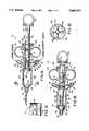
- FIG. 1Ais a partial cross-sectional view of a limited backflow reflux valve including a plunger and plunger lock in accordance with principles of the present invention, shown with the plunger and piston at their rearwardmost positions.
- FIG. 1Bis a view of the limited backflow reflux valve of FIG. 1A shown with the plunger and piston at their forwardmost positions.
- FIG. 1Cis a partial view of an alternative embodiment of teeth 35 and 35a.
- FIG. 1Dis a cross-sectional view of the valve of FIG. 1A taken on lines 1D--1D.
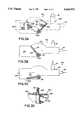
- FIG. 2Ais a cross-sectional view of a second embodiment of a limited backflow reflux valve in accordance with principles of the present invention, shown with the piston at its rearwardmost position.
- FIG. 2Bis a view of the limited backflow reflux valve of FIG. 2A shown with the piston at its forwardmost position.
- FIG. 2Cis a cross-sectional view of the valve of FIG. 2A taken on lines 2C--2C.
- FIG. 3Ais a schematic isometric view of a third embodiment of a limited backflow check valve in accordance with principles of the present invention, shown with the gate at its rearwardmost position.
- FIGS. 3Bis a schematic views of the limited backflow check valve of FIG. 3A shown with the gate at the position achieved in the absence of fluid flow
- FIG. 3Cis a schematic view of this valve shown with the gate at the position achieved during forward fluid flow.
- FIG. 3Dis an elevation view of the axle and spring assembly of the valve of FIGS. 3A-3D.
- a limited backflow reflux valve 10in accordance with principles of the present invention includes three ports for fluid flow into and out of the valve 10.
- Outlet port 12includes a standard luer fitting sized for connection to the tubing leading to a catheter (not shown).
- Inlet port 16is sized for connection to a syringe of a power injector of the type used to inject fluid into the patient.
- Bi-directional port 14is sized for connection to a bulk container of contrast media via suitable tubing.
- Valve 10includes a main cylindrical housing section 18, and a second cylindrical housing section 20 having a smaller diameter than main housing section 18.
- a piston 22is seated in main housing section 18 and may slide transversely through this section as shown in FIG. 1A in comparison to FIG. 1B.
- Piston 22is mounted to a plunger 26 by insertion of an extension 27 at the rear of piston 22 into a recess 28 in plunger 26.
- a sealing ring 24Seated between piston 22 and plunger 26 is a sealing ring 24 which encircles the outer edge of piston 22 and engages the circular inner wall 29 of housing section 18 to form a fluid seal therewith.
- Sealing ring 24is manufactured of a resilient material such as rubber and is cupped at its peripheral rim; accordingly, under fluid pressure ring 24 will resiliently yield to permit fluid to flow from the rear side of ring 24 (the side from which plunger 26 extends) to the forward side of ring 24 (the side having the body of piston 22). However, if fluid pressure is removed or reversed, sealing ring 24 will re-engage the cylindrical wall 29 of section 18 and will form a fluid-tight seal preventing fluid flow in the opposite direction from the forward side of ring 24 to the rearward side of ring 24.
- Plunger 26extends rearwardly through housing section 20, emerges from housing section 20, and terminates in a thumb grip 30.
- a pair of sealing rings 32Centrally located along the length of plunger 26 is a pair of sealing rings 32 which engages the inner surface 31 of housing section 20 to form a seal therewith and prevent fluid from escaping from housing section 20.
- Housing section 20has, on its outer sides, finger grips 34. Grips 30 and 34 are sized and positioned so that a physician's fingers may be placed in grips 34 and the thumb from the same hand placed in grip 30, so that plunger 26 may be manually driven into or retracted from housing sections 18 and 20.
- plunger 26rearward of sealing rings 32, carries a number of teeth 35, which extend from plunger 26 along a substantial portion of the length of plunger 26. However, a rearwardmost auto withdrawal zone 33 of plunger 26 does not bear any teeth, for reasons that will be noted below.
- twist-lock 37is journalled to a flange 38 on housing section 20.
- Twist-lock 37carries one or more teeth 35a (one being shown in the Figures) which can be rotated such that the tooth or teeth on twist-lock 37 mate to and engage the teeth 35 on plunger 26. Accordingly, by rotating twist-lock 37, plunger 26 may be locked in a given axial location or left free to slide axially within housing section 20.
- a torsion spring 37amay be included in the journalled connection between twist-lock 37 and housing section 20, producing a force tending to rotate twist-lock 37 into engagement with teeth 35 on plunger 26 and thereby lock plunger 26 in place.
- a snap-fitting(not shown) may be included in the twist-lock 37 to permit the twist-lock 37 to be rotated and held in its unlocked position against the force of the torsion spring 37a.
- teeth 35 and 35aare barbed, such that twist-lock 37 will not prevent forward motion of plunger 26 within the housing of syringe 10, but will prevent rearward motion of plunger 26 within the housing.
- Inlet port 16is in fluid communication with the interior of housing sections 18 and 20 through a check valve barrel 36.
- Barrel 36communicates with the interior of housing section 20 at a position which is always forward of sealing rings 32 even when piston 22 and plunger 26 are at their forwardmost positions (FIG. 1B). This position is also always rearward of sealing ring 24 even when piston is at its rearwardmost position (FIG. 1A).
- a check valve ball 39is positioned inside of barrel 36.
- a spring 40is compressed inside barrel 36 with ball 39 to produce a positive force urging ball 39 toward the outer wall 41 of barrel 36. Barrel 36, ball 39 and spring 40 cooperate to form a check valve which permits fluid flow through inlet port 16 into the housing of valve 10 but prevents fluid flow through inlet port out of the housing of valve 10.
- Bi-directional port 14is also in fluid communication with the interior of housing section 20 via a channel 42.
- Channel 42communicates with housing section 20 at a position opposite to barrel 36, i.e., at a position which is always forward of sealing rings 32 even when piston 22 and plunger 26 are at their forwardmost position (FIG. 1B) and which is always rearward of sealing ring 24 even when piston 22 is at its rearwardmost position (FIG. 1A).
- Housing section 18terminates, at its forward end, in a conical end cap 44 having a shape which is congruent to the conical piston 22.
- end cap 44Positioned within end cap 44 are spacer ribs 46 which project inwardly from the conical surfaces of end cap 44. Four such ribs 46 are shown in FIG. 1D although fewer or more ribs could be included.
- Housing section 18terminates, at its rearward end, in a second conical end cap 48 which mates with a conical surface on plunger 26.
- the interior surface of end cap 48does not carry ribs or spacers, so that when the plunger is translated to its fully-rearward position, the conical surface of plunger 26 may mate fully with the conical interior surface of end cap 48 to form a fluid-tight connection.
- the above-described limited backflow reflux valve 10may be used in a number of different ways to perform an injection procedure, some of which are described below for exemplary purposes. These procedures will be described with reference to the injection of contrast media into an animal patient for the purpose of improving CT, Angiographic, Magnetic Resonance or Ultrasound imaging. Due to the cost of contrast media, the advantages of the invention are particularly dramatic in such injections; however, numerous other similar injection procedures could be performed using the above-described valve 10 with like effects.
- a first stepis to fill the syringe on the power injector with contrast media for the injection.
- This stepis performed by coupling a bulk container of contrast media (such as a bag, cup, or bottle) to inlet port 16, and coupling the syringe to bi-directional port 14.
- the power injectoris run in reverse to withdraw air and fluid into the syringe. This reduces the pressure inside of housing section 18 and 20 in the region forward of sealing rings 32 and rearward of sealing ring 24.
- the cupped shape of sealing ring 24causes sealing ring 24 to maintain a tight seal against housing section 18, preventing air from passing sealing ring 24.
- sealing ring 24is configured for low-friction operation so that plunger 26 will be drawn rearwardly prior to the introduction of fluid through inlet port 16.
- plunger 26should be retracted to its rearwardmost position, or alternatively twist-lock 37 should be rotated and snapped or manually held in its disengaged position, so that piston 22 and plunger 26 will translate to the position shown in FIG. 1A prior to the introduction of fluid through inlet port 16.
- valve 10is supplied from the manufacturer with plunger 26 already in its fully-rearward position. In this case, it is unnecessary to move plunger 26 to its rearwardmost position or to snap or manually hold twist-lock 37 in its disengaged position during initial filling through valve 10. (Since valve 10 comes in contact with blood from the patient, it must be disposed after use; therefore, the valve 10 will only be used for one refilling procedure, and so if valve 10 is supplied with plunger 26 in its fully rearward position, the plunger 26 will be in this position during initial filling.)
- valve 10As a final aside, it should be noted that if barbed teeth (FIG. 1C) are used, and valve 10 is supplied from the manufacturer with plunger 26 in its rearwardmost position, the valve 10 need not be provided with a snap for holding twist-lock 37 in its disengaged position, since in such a case all procedures requiring disengagement of twist-lock 37 are performed manually, and in such cases twist-lock 37 can be easily manually disengaged by hand in a manner described below.
- valve 10When the desired amount of contrast media has been drawn through valve 10 and into the syringe, the backward motion of the power injector is terminated. At this instant, the pressure inside of valve 10 is equalized, and as a result the compression force of spring 40 forces ball 39 to engage to the outward end of check valve barrel 36, sealing inlet port 16 from the interior of valve 10.
- a length of high pressure tubingfor connection to the catheter, is attached to the outlet port 12 of valve 10.
- the power injectoris then run forward to force any air in the syringe into valve 10 and out through the high pressure tubing.
- the power injectoris typically tilted upwards so that any air in the power injector syringe moves to the nozzle of the syringe.
- valve 10be tilted upward so that outlet port 12 is elevated relative to the remainder of valve 10 so that gravity causes any air bubbles entrained in valve 10 to move to and out of outlet port 12.
- the tubing at outlet port 12may be connected to the catheter and the catheter inserted into the patient.
- twist-lock 37is disengaged to permit free movement of plunger 26 and piston 22. Then, to perform a small-volume injection, the physician or technician grasps valve 10 with his/her thumb and two fingers using grips 30 and 34, and manually moves plunger 26 and piston 22 rearwardly and forwardly to pump small amounts of contrast media through the catheter and into the patient. For this operation, twist-lock 37 must be disengaged, which can be done by rotating twist-lock 37 with a third finger on the same hand used to grasp grips 30 and 34.
- valve 10When piston 22 is manually urged rearwardly, a positive pressure is developed inside the housing of valve 10 in the region rearward of sealing ring 24. When this pressure reaches a sufficient level, it overcomes the resilient force produced by the cupped exterior of sealing ring 24, permitting contrast media to flow around piston 22 from the rearward side of sealing ring 24 to the front side of sealing ring 24. Thereafter, when piston 22 is manually urged forwardly, a positive pressure is developed inside of valve 10 in the region forward of sealing ring 24. This positive pressure enhances the seal of sealing ring 24, such that no fluid may flow around sealing ring 24. Accordingly, when the pressure reaches a level greater than the patient's blood pressure, contrast media is injected from the portion of valve 10 forward of sealing ring 24 into the patient through the catheter. At the same time, as piston 22 moves forward, a negative pressure is developed in the portion of valve 10 rearward of sealing ring 24. This negative pressure eventually overcomes the compression force of spring 40, such that additional contrast media is supplied to valve 10 through inlet port 16.
- contrast mediamay be injected into the patient in small, measured quantities by repeated forward and reverse motion of plunger 26.
- a large-scale injection of contrast mediamay be performed by activating the power injector. Doing so will cause contrast media to flow into valve 10 through bi-directional port 14, initially translating piston 22 to its forwardmost position (if twist-lock 37 is disengaged or has barbed teeth) and thereafter forcing fluid flow around sealing ring 24. (Once sealing ring 24 has been deflected by forward flow of fluid through valve 10, the cross-sectional area of the gap between sealing ring 24 and the interior of housing section 18 is larger than the cross-sectional area of the syringe nozzle and tubing; therefore, valve 10 does not produce any substantial resistance to fluid flow at even high flow rates.)
- plunger 26it may be desirable for plunger 26 to be placed in its fully-forward position during an injection procedure. If barbed teeth are used, such positioning will be automatically achieved from the natural motion of plunger 26 in response to fluid pressures in the valve 10. However, if barbed teeth are note used, plunger 26 must be manually moved to its fully-forward position, or twist-lock 37 must be disengaged during injection so that plunger 26 naturally moves forward in response to fluid pressures in the valve 10.
- plunger 26It may be desirable to position plunger 26 at its fully-forward position because, at any time during the injection procedure, the physician may wish to extravasate blood through the catheter and into the tubing to check for patency of the catheter. To do so, the physician operates the power injector in reverse, producing a negative pressure inside of the syringe. If piston 22 and plunger 26 are at their forwardmost position, they will respond to this negative pressure by moving rearwardly (in the same manner as discussed above with respect to initial filling of the syringe), drawing blood out of the patient and into the catheter. When blood becomes visible in the tubing, it can be confirmed that the catheter is not blocked.
- twist-lock 37should be in position to engage with the teeth 35 on plunger 26.
- twist-lock 37since there are no teeth in the auto-withdrawal zone 33 of the plunger 26, if plunger 26 is fully forward at the beginning of withdrawal, twist-lock 37 will be unable to engage plunger 26, and plunger 26 will be able to move rearwardly out of the housing of valve 10 for a distance equal to the length of the auto-withdrawal zone. Thereafter, twist-lock 37 will engage teeth 35 in plunger 26 and prevent further movement.
- a controlled, limited volume of bloodcan be withdrawal from the patient before engagement of the twist-lock 37.
- twist-lock 37will engage the teeth on plunger 26 and prevent further withdrawal, so that further rearward motion of the power injector will not withdraw blood, but rather will draw fluid into valve 10 through inlet port 16 in the manner discussed above with respect to filling the syringe.
- the twist-lock 37interacting with plunger 26, causes a predetermined quantity of fluid (e.g., 2 ml) to be withdrawn from the patient by operation of the power injector, without the need for highly accurate operation of the power injector.
- This predetermined quantitycan be selected to be less than the total volume of the tubing and catheter, such that blood is unable to reach valve 10, preventing contamination.
- sealing ring 24is tightly sealed to the interior of housing section 18 during withdrawal, any blood withdrawn from the patient into valve 10 is contained within valve 10 in the region forward of sealing ring 24, avoiding contamination of either the power injector syringe connected to port 14 or the bulk contrast media container connected to port 16.
- a typical small catheter for a non-angiographic procedureis about 3 inches long and 0.02 inches inside diameter, resulting in a volume of 0.015 ml captured in the catheter.
- a typical small catheter for an angiographic procedureis about 10 inches long and 0.03 inches inside diameter, resulting in a volume of 0.116 ml captured in the catheter.
- a typical large catheter (for angiography)is 40 inches long and 0.05 inches inside diameter, resulting a volume of 1.287 ml captured in the catheter.
- the technicianneed only operate the syringe in reverse, which (possibly after initial withdrawal of a limited volume of blood into the catheter) will cause additional contrast media to flow from the bulk container through inlet port 16 and refill the syringe.
- the syringemay be refilled at any time during the procedure, without disconnecting tubing and without risk of contamination of introduction of air.
- the simplified valve 100includes, as before, an outlet port 12 for connection to tubing leading to a catheter, a bi-directional port 14 for connection to a syringe, and an inlet port 16 for connection to a bulk container of injection fluid.
- inlet port 16includes a check valve barrel 36, ball 39 and spring 40 which collectively provide a check valve function to allow fluid to flow into valve 100 through port 16 but not outward through port 16.
- the housing of syringe 100also includes a main cylindrical section 18 and a secondary section 20, and a piston 102 translates axially through section 18 in response to pressure and fluid flow within valve 100.
- piston 102includes an integral rearward section which extends rearwardly through housing section 20 and terminates in a bulb 104.
- piston 102 and bulb 104, and the connecting elastic element 106are a single, integral element, formed of a flexible material that can stretch resiliently to a great extent, such as silicon rubber.
- Connecting elastic element 106provides a resilient force tending to move piston 102 rearwardly, as discussed below.
- bulb 104is held against four ribs 107 (see FIG. 2C), positioned within housing section 20 in a manner which engages bulb 104 and prevents bulb 104 from moving forwardly toward housing section 18.
- housing section 18includes, as before, a conical end cap 44.
- End cap 44also includes ridges 46 which, as before, extend inwardly from end cap 44 and prevent piston 102 from engaging fully against end cap 44, such that a small radial gap 47 is left between piston 102 and end cap 44 even when piston 102 is at its fully forward position shown in FIG. 2B.
- housing section 18This forwardmost end of housing section 18 is enlarged in diameter, so that, as best seen in FIG. 2B, when piston 102 reaches its forwardmost position, the periphery of piston 102 is no longer able to seal against the internal surfaces of housing section 18, and therefore fluid is able to flow around piston 102, through the gap 47 between piston 102 and end cap 44, and out of outlet port 12. So long as fluid flow continues in this direction, piston 102 will be held against ridges 46 and will not re-engage the periphery of housing section 18.
- housing section 18includes a similar conical section.
- This sectionincludes a circumferential ridge 108 which engages piston 102 when piston 102 is at its rearwardmost position shown in FIG. 2A, thereby sealing piston 102 and ensuring there can be no fluid flow around piston 102 when in this rearwardmost position.
- the simplified limited backflow reflux valve 100performs similarly to the valve discussed in FIGS. 1A and 1B, with the exception that there is no provision for manual injection using the valve.
- the procedurewill again be discussed in the context of a contrast media injection, although other injection procedures could use valve 100 with like results.
- the first step in using the valveis to fill the syringe.
- a bulk container of contrast mediais coupled to inlet port 16, and the syringe is coupled to bi-directional port 14.
- the power injectoris run in reverse to withdraw air and fluid into the syringe. This motion reduces the pressure inside of housing section 18 and 20 in the region piston 102 rearward of sealing ring 24.
- This initial pressure drop produced by reverse operation of the power injectorcauses piston 102 to move rearwardly through housing section 18 to the position shown in FIG. 2A, at which time piston 102 ceases motion.
- valve 100is typically disposable and may be provided with piston 102 pre-positioned as shown in FIG. 2A.
- valve 100When the desired amount of contrast media has been drawn through valve 100 and into the syringe, the backward motion of the power injector is terminated. At this instant, the pressure inside of valve 100 is equalized, and as a result the compression force of spring 40 forces ball 39 to engage to the outward end of check valve barrel 36, sealing inlet port 16 from the interior of valve 100.
- valve 100After thus filling the power injector syringe, a length of high pressure tubing, for connection to the catheter, is attached to the outlet port 12 of valve 100.
- the power injectoris then run forward to force any air in the syringe into valve 100 and out through the high pressure tubing.
- the power injectoris typically tilted upwards so that any air in the power injector syringe moves to the nozzle of the syringe.
- valve 100may be tilted upward so that outlet port 12 is elevated relative to the remainder of valve 100 so that gravity causes any air bubbles entrained in valve 100 to move to and out of outlet port 12.
- the tubing at outlet port 12may be connected to the catheter and the catheter inserted into the patient.
- a large-scale injection of contrast mediamay be performed by activating the power injector. Doing so will cause contrast media to flow into valve 100 through bi-directional port 14, initially translating piston 102 to its forwardmost position and thereafter forcing fluid flow around piston 102 in this position.
- the physicianmay wish to withdraw blood through the catheter and into the tubing to check for patency of the catheter.
- the physicianoperates the power injector in reverse, producing a negative pressure inside of the syringe.
- piston 102will be at the forward end of housing section 18, and will respond to this negative pressure by moving rearwardly (in the same manner as discussed above with respect to initial filling of the syringe), drawing blood out of the patient and into the catheter.
- blood becomes visible in the tubingit can be confirmed that the catheter is not blocked.
- piston 102Once piston 102 reaches the rearwardmost position shown in FIG. 2A, further rearward motion of the power injector will draw fluid into valve 100 through inlet port 16 in the manner discussed above with respect to filling the syringe.
- valve 100permits a predetermined quantity of fluid (e.g., 2 ml) to be withdraw from the patient by operation of the power injector, without the need for highly accurate operation of the power injector. Furthermore, because piston 102 is tightly sealed to the interior of housing section 18 during withdrawal, any blood withdrawn from the patient into valve 100 is contained within valve 100 in the region forward of piston 102, avoiding contamination of either the power injector syringe connected to port 14 or the bulk contrast media container connected to port 16.
- a predetermined quantity of fluide.g., 2 ml
- the technicianneed only operate the syringe in reverse, which (after initial withdrawal of a limited volume of blood into the catheter) will cause additional contrast media to flow from the bulk container through inlet port 16 and refill the syringe.
- the syringemay be refilled at any time during the procedure, without disconnecting tubing and without risk of contamination of introduction of air.
- FIG. 3Aillustrates a valve 110 including a hinged gate 112 which rotates within a fluid channel 114 to permit unlimited forward flow and limited backflow through the channel 114.
- gate 112rotates or pivots about an axle 116 within housing 120 to perform these functions.
- gate 112pivots counter-clockwise to its open position shown in FIG. 3C to permit fluid to pass unimpeded.
- a spring 118 mounted to the axis of rotationcauses gate 112 to pivot clockwise to the sealing position shown in FIG. 3B, thus sealing the fluid channel 114.
- gate 112will pivot further counterclockwise until it reaches the position shown in FIG. 3A, at which time gate 112 engages the housing, preventing further pivoting and preventing further fluid flow. It will be noted that gate 112 carries a sealing rim 122 which seals against the interior walls of the valve housing 120 and prevents fluid flow around gate 112 when gate 112 is at or between the positions shown in FIGS. 3A and 3B.
- a torsional spring 118attached to the axle 116 of gate 112, returns gate 112 to the position shown in FIG. 3B by applying a counter-clockwise torque to gate 112.
- FIGS. 3A-3DThe limited backflow check valve structure shown in FIGS. 3A-3D, or any other valve structure achieving these functions, could therefore be substituted for the piston 102 and main cylindrical housing section 18 in the embodiment of the invention shown in FIG. 2A-2B and achieve similar results.
- valve structures described abovecould be integrally manufactured with a bulk container of contrast media, or a disposable syringe, or both, simplifying assembly and reducing cost.
- the various functional elements of the valvecould be incorporated in a single housing, as shown in the Figures, or in separate housings interconnected by tubing.
- a cupped valve structurecould be used in the simplified valve of FIGS. 2A-2B, thus permitting fluid flow around the piston in the manner discussed above with reference to FIGS.
- FIGS. 1A-1Bwithout necessitating the inclusion of an enlarged region in the main cylindrical housing section 18 (although such an approach might require manufacture of a two-piece piston such as is shown in FIGS. 1A-1B).
- other plunger locking structurescould be used in place of those illustrated in FIGS. 1A and 1B, for example a friction-engagement lock in place of a toothed lock.
- the valvemay be supplied pre-filled with contrast to simplify the procedures for initial connection and use of the valve.
- the invention in its broader aspectsis therefore not limited to the specific details, representative apparatus and method, and illustrative example shown and described. Accordingly, departures may be made from such details without departing from the spirit or scope of applicant's general inventive concept.
Landscapes
- Health & Medical Sciences (AREA)
- Vascular Medicine (AREA)
- Engineering & Computer Science (AREA)
- Anesthesiology (AREA)
- Biomedical Technology (AREA)
- Heart & Thoracic Surgery (AREA)
- Hematology (AREA)
- Life Sciences & Earth Sciences (AREA)
- Animal Behavior & Ethology (AREA)
- General Health & Medical Sciences (AREA)
- Public Health (AREA)
- Veterinary Medicine (AREA)
- Infusion, Injection, And Reservoir Apparatuses (AREA)
- Saccharide Compounds (AREA)
- Check Valves (AREA)
Abstract
Description
Claims (32)
Priority Applications (9)
| Application Number | Priority Date | Filing Date | Title |
|---|---|---|---|
| US08/535,771US5665074A (en) | 1995-09-28 | 1995-09-28 | Limited backflow reflux valve |
| JP51353097AJP4270409B2 (en) | 1995-09-28 | 1996-09-20 | Limited backflow recirculation valve |
| DE69634264TDE69634264T2 (en) | 1995-09-28 | 1996-09-20 | CHECK VALVE WITH LIMITED FLOW |
| EP96935910AEP0863777B1 (en) | 1995-09-28 | 1996-09-20 | Limited backflow reflux valve |
| PCT/US1996/015210WO1997011730A1 (en) | 1995-09-28 | 1996-09-20 | Limited backflow reflux valve |
| ES96935910TES2232841T3 (en) | 1995-09-28 | 1996-09-20 | LIMITED COUNTERFLOW REFLUX VALVE. |
| AU73688/96AAU7368896A (en) | 1995-09-28 | 1996-09-20 | Limited backflow reflux valve |
| AT96935910TATE287737T1 (en) | 1995-09-28 | 1996-09-20 | CHECK VALVE WITH LIMITED RETURN FLOW |
| US08/841,287US5743872A (en) | 1995-09-28 | 1997-04-29 | Limited backflow reflux valve and method |
Applications Claiming Priority (1)
| Application Number | Priority Date | Filing Date | Title |
|---|---|---|---|
| US08/535,771US5665074A (en) | 1995-09-28 | 1995-09-28 | Limited backflow reflux valve |
Related Child Applications (1)
| Application Number | Title | Priority Date | Filing Date |
|---|---|---|---|
| US08/841,287DivisionUS5743872A (en) | 1995-09-28 | 1997-04-29 | Limited backflow reflux valve and method |
Publications (1)
| Publication Number | Publication Date |
|---|---|
| US5665074Atrue US5665074A (en) | 1997-09-09 |
Family
ID=24135700
Family Applications (2)
| Application Number | Title | Priority Date | Filing Date |
|---|---|---|---|
| US08/535,771Expired - LifetimeUS5665074A (en) | 1995-09-28 | 1995-09-28 | Limited backflow reflux valve |
| US08/841,287Expired - LifetimeUS5743872A (en) | 1995-09-28 | 1997-04-29 | Limited backflow reflux valve and method |
Family Applications After (1)
| Application Number | Title | Priority Date | Filing Date |
|---|---|---|---|
| US08/841,287Expired - LifetimeUS5743872A (en) | 1995-09-28 | 1997-04-29 | Limited backflow reflux valve and method |
Country Status (8)
| Country | Link |
|---|---|
| US (2) | US5665074A (en) |
| EP (1) | EP0863777B1 (en) |
| JP (1) | JP4270409B2 (en) |
| AT (1) | ATE287737T1 (en) |
| AU (1) | AU7368896A (en) |
| DE (1) | DE69634264T2 (en) |
| ES (1) | ES2232841T3 (en) |
| WO (1) | WO1997011730A1 (en) |
Cited By (36)
| Publication number | Priority date | Publication date | Assignee | Title |
|---|---|---|---|---|
| WO1999019008A1 (en)* | 1997-10-14 | 1999-04-22 | Merit Medical Systems, Inc. | Pulse fluid infusion systems |
| US6019350A (en)* | 1997-03-05 | 2000-02-01 | Gelbfish; Gary A. | Hand held control device and associated method |
| US6126618A (en)* | 1999-01-14 | 2000-10-03 | Baxter International Inc. | Apparatus for obtaining liquid samples |
| US6355024B1 (en) | 1999-07-14 | 2002-03-12 | Mallinckrodt Inc. | Medical fluid delivery system |
| US6360784B1 (en)* | 1999-12-22 | 2002-03-26 | Medtronic, Inc. | Valved connector and method of use |
| US6387086B2 (en) | 1999-07-29 | 2002-05-14 | Baxter International Inc. | Blood processing set including an integrated blood sampling system |
| US6419662B1 (en)* | 2001-01-30 | 2002-07-16 | Anthony Solazzo | Continuous irrigation Y-tubing control valve device and system |
| US6468261B1 (en) | 1999-07-14 | 2002-10-22 | Mallinckrodt Inc. | Medical fluid delivery system |
| US6471674B1 (en) | 2000-04-21 | 2002-10-29 | Medrad, Inc. | Fluid delivery systems, injector systems and methods of fluid delivery |
| US6520937B2 (en) | 2000-12-18 | 2003-02-18 | Scimed Life Systems, Inc. | Fluid injection device |
| US20040133165A1 (en)* | 1995-04-20 | 2004-07-08 | Doug Duchon | Angiographic injector and injection method |
| US20040181192A1 (en)* | 2003-03-11 | 2004-09-16 | Cuppy Michael John | Vascular access device and method of using same |
| US20040221904A1 (en)* | 2003-05-06 | 2004-11-11 | Usher Kathryn Mary | Fluid manifold control device |
| US20050194047A1 (en)* | 2004-03-05 | 2005-09-08 | Liebel-Flarsheim Company | Check valve for a fluid administration system |
| US7044941B2 (en) | 1999-07-29 | 2006-05-16 | Baxter International Inc. | Method and apparatus for collecting blood samples prior to a blood collection procedure |
| US7172572B2 (en) | 2001-10-04 | 2007-02-06 | Boston Scientific Scimed, Inc. | Manifold system for a medical device |
| US20080172006A1 (en)* | 2007-01-15 | 2008-07-17 | Medrad, Inc. | Patency Check Compatible Check Valve And Fluid Delivery System Including The Patency Check Compatible Check Valve |
| US20090159086A1 (en)* | 2007-12-21 | 2009-06-25 | Massachusetts Eye & Ear Infirmary | Cricothyrotomy device |
| US7824343B2 (en) | 1999-07-29 | 2010-11-02 | Fenwal, Inc. | Method and apparatus for blood sampling |
| US20110114197A1 (en)* | 2001-12-07 | 2011-05-19 | Acist Medical Systems, Inc. | Low pressure measurement devices in high pressure environments |
| US20130090572A1 (en)* | 2011-10-07 | 2013-04-11 | Robert Bilgor Peliks | Integrity Testing Method and Apparatus for Delivering Vapor to the Uterus |
| US8945051B2 (en) | 2009-07-24 | 2015-02-03 | Bayer Medical Care Inc. | Multi-fluid medical injector system and methods of operation |
| US9108047B2 (en) | 2010-06-04 | 2015-08-18 | Bayer Medical Care Inc. | System and method for planning and monitoring multi-dose radiopharmaceutical usage on radiopharmaceutical injectors |
| US9743974B2 (en) | 2010-11-09 | 2017-08-29 | Aegea Medical Inc. | Positioning method and apparatus for delivering vapor to the uterus |
| US9956377B2 (en) | 2002-09-20 | 2018-05-01 | Angiodynamics, Inc. | Method and apparatus for intra-aortic substance delivery to a branch vessel |
| US9993290B2 (en) | 2014-05-22 | 2018-06-12 | Aegea Medical Inc. | Systems and methods for performing endometrial ablation |
| US10154871B2 (en) | 2007-08-23 | 2018-12-18 | Aegea Medical Inc. | Uterine therapy device and method |
| US10179019B2 (en) | 2014-05-22 | 2019-01-15 | Aegea Medical Inc. | Integrity testing method and apparatus for delivering vapor to the uterus |
| US10279112B2 (en) | 2012-09-24 | 2019-05-07 | Angiodynamics, Inc. | Power injector device and method of use |
| CN110871627A (en)* | 2018-08-31 | 2020-03-10 | 鸿富锦精密工业(深圳)有限公司 | Check Valves, Continuous Ink Systems and Printers |
| US11207118B2 (en) | 2007-07-06 | 2021-12-28 | Tsunami Medtech, Llc | Medical system and method of use |
| US11284931B2 (en) | 2009-02-03 | 2022-03-29 | Tsunami Medtech, Llc | Medical systems and methods for ablating and absorbing tissue |
| US11331037B2 (en) | 2016-02-19 | 2022-05-17 | Aegea Medical Inc. | Methods and apparatus for determining the integrity of a bodily cavity |
| US11369739B2 (en) | 2013-01-21 | 2022-06-28 | Medline Industries, Lp | Method to provide injection system parameters for injecting fluid into patient |
| US11413086B2 (en) | 2013-03-15 | 2022-08-16 | Tsunami Medtech, Llc | Medical system and method of use |
| US20240000477A1 (en)* | 2017-08-29 | 2024-01-04 | Boston Scientific Scimed, Inc. | Medical device with a flow controller |
Families Citing this family (19)
| Publication number | Priority date | Publication date | Assignee | Title |
|---|---|---|---|---|
| GB9111049D0 (en)* | 1991-05-22 | 1991-07-17 | Parkin Adrian | Hypodermic needle |
| US6221045B1 (en)* | 1995-04-20 | 2001-04-24 | Acist Medical Systems, Inc. | Angiographic injector system with automatic high/low pressure switching |
| DE19723648C1 (en) | 1997-06-05 | 1998-08-27 | Disetronic Licensing Ag | Controlled infusion equipment with leak and reverse flow prevention used e.g. in insulin therapy |
| DE19814047C1 (en)* | 1998-03-30 | 1999-05-06 | Fresenius Medical Care De Gmbh | Patient connector for kidney dialysis machine |
| US6235002B1 (en)* | 1998-04-17 | 2001-05-22 | Cdc Technologies, Inc. | Syringe for use in fluid-handling apparatus |
| DE19822031C2 (en) | 1998-05-15 | 2000-03-23 | Disetronic Licensing Ag | Auto injection device |
| DE19840992A1 (en) | 1998-09-08 | 2000-03-09 | Disetronic Licensing Ag | Pressure monitoring of a product fluid to be administered in doses during an infusion or injection |
| US6626862B1 (en)* | 2000-04-04 | 2003-09-30 | Acist Medical Systems, Inc. | Fluid management and component detection system |
| US6921378B2 (en)* | 2001-10-09 | 2005-07-26 | Boston Scientific Scimed, Inc. | Anti-reflux drainage devices and methods |
| US6579263B1 (en)* | 2002-01-11 | 2003-06-17 | Milton Chernack | Method and apparatus for the delivery of contrast fluid to a patient |
| CN101516434B (en)* | 2006-10-18 | 2011-09-07 | 泰尔茂株式会社 | Medical apparatus |
| US20090143723A1 (en)* | 2007-11-29 | 2009-06-04 | Baxter International Inc. | Flow control device for peritoneal dialysis |
| US20090204078A1 (en)* | 2008-02-13 | 2009-08-13 | Boston Scientific Scimed, Inc. | Manifold and Valve Seal for Use with a Medical Device |
| US8728038B2 (en)* | 2011-12-29 | 2014-05-20 | William L. Spearman | Method and apparatus for accessing blood from an IV catheter insertion device |
| US8702658B2 (en)* | 2011-12-29 | 2014-04-22 | William L. Spearman | IV catheter insertion device and method |
| US20170143894A1 (en)* | 2014-06-27 | 2017-05-25 | Bayer Healthcare Llc | Inline patency check device |
| WO2017127482A1 (en)* | 2016-01-22 | 2017-07-27 | Hodak Michael L | One-way check valve |
| CN108784754B (en)* | 2018-04-18 | 2021-05-28 | 河南科技大学第一附属医院 | A lung biopsy device |
| EP3669633B1 (en) | 2018-12-18 | 2022-02-09 | CNH Industrial Belgium NV | A header drive mechanism for a combine harvester |
Citations (11)
| Publication number | Priority date | Publication date | Assignee | Title |
|---|---|---|---|---|
| US3957051A (en)* | 1974-09-13 | 1976-05-18 | Medical Development Corporation | Pump-type syringe having double-acting piston construction |
| US4210173A (en)* | 1976-12-06 | 1980-07-01 | American Hospital Supply Corporation | Syringe pumping system with valves |
| US4246932A (en)* | 1979-10-18 | 1981-01-27 | Burron Medical, Inc. | Multiple additive valve assembly |
| US4341224A (en)* | 1980-02-04 | 1982-07-27 | Gould Inc. | Catheter flushing apparatus |
| US4546791A (en)* | 1984-03-20 | 1985-10-15 | Huang E Jen | Safety valve |
| US4668215A (en)* | 1986-05-15 | 1987-05-26 | Dexide, Inc. | Irrigator-evacuator control for surgical procedures |
| US4729401A (en)* | 1987-01-29 | 1988-03-08 | Burron Medical Inc. | Aspiration assembly having dual co-axial check valves |
| US5034000A (en)* | 1989-03-28 | 1991-07-23 | Dexide, Incorporated | Medical evacuation and irrigation device |
| US5129416A (en)* | 1990-07-20 | 1992-07-14 | Watts Regulator Company | Anti-siphon frost-proof water hydrant |
| US5148828A (en)* | 1991-03-29 | 1992-09-22 | The Ford Meter Box Co., Inc. | Check valve assembly |
| US5423751A (en)* | 1993-02-18 | 1995-06-13 | Harrison; Samuel W. | Contrast media dispensing apparatus |
Family Cites Families (2)
| Publication number | Priority date | Publication date | Assignee | Title |
|---|---|---|---|---|
| DE3518575A1 (en)* | 1985-04-19 | 1986-10-23 | Baxter Travenol Laboratories, Inc., Deerfield, Ill. | Multi-way valve |
| DE9114493U1 (en)* | 1991-11-21 | 1992-01-16 | Transcoject Gesellschaft für medizinische Geräte mbH & Co KG, 2350 Neumünster | Valve arrangement |
- 1995
- 1995-09-28USUS08/535,771patent/US5665074A/ennot_activeExpired - Lifetime
- 1996
- 1996-09-20ATAT96935910Tpatent/ATE287737T1/ennot_activeIP Right Cessation
- 1996-09-20ESES96935910Tpatent/ES2232841T3/ennot_activeExpired - Lifetime
- 1996-09-20WOPCT/US1996/015210patent/WO1997011730A1/enactiveIP Right Grant
- 1996-09-20JPJP51353097Apatent/JP4270409B2/ennot_activeExpired - Lifetime
- 1996-09-20DEDE69634264Tpatent/DE69634264T2/ennot_activeExpired - Lifetime
- 1996-09-20AUAU73688/96Apatent/AU7368896A/ennot_activeAbandoned
- 1996-09-20EPEP96935910Apatent/EP0863777B1/ennot_activeExpired - Lifetime
- 1997
- 1997-04-29USUS08/841,287patent/US5743872A/ennot_activeExpired - Lifetime
Patent Citations (11)
| Publication number | Priority date | Publication date | Assignee | Title |
|---|---|---|---|---|
| US3957051A (en)* | 1974-09-13 | 1976-05-18 | Medical Development Corporation | Pump-type syringe having double-acting piston construction |
| US4210173A (en)* | 1976-12-06 | 1980-07-01 | American Hospital Supply Corporation | Syringe pumping system with valves |
| US4246932A (en)* | 1979-10-18 | 1981-01-27 | Burron Medical, Inc. | Multiple additive valve assembly |
| US4341224A (en)* | 1980-02-04 | 1982-07-27 | Gould Inc. | Catheter flushing apparatus |
| US4546791A (en)* | 1984-03-20 | 1985-10-15 | Huang E Jen | Safety valve |
| US4668215A (en)* | 1986-05-15 | 1987-05-26 | Dexide, Inc. | Irrigator-evacuator control for surgical procedures |
| US4729401A (en)* | 1987-01-29 | 1988-03-08 | Burron Medical Inc. | Aspiration assembly having dual co-axial check valves |
| US5034000A (en)* | 1989-03-28 | 1991-07-23 | Dexide, Incorporated | Medical evacuation and irrigation device |
| US5129416A (en)* | 1990-07-20 | 1992-07-14 | Watts Regulator Company | Anti-siphon frost-proof water hydrant |
| US5148828A (en)* | 1991-03-29 | 1992-09-22 | The Ford Meter Box Co., Inc. | Check valve assembly |
| US5423751A (en)* | 1993-02-18 | 1995-06-13 | Harrison; Samuel W. | Contrast media dispensing apparatus |
Cited By (71)
| Publication number | Priority date | Publication date | Assignee | Title |
|---|---|---|---|---|
| US7959605B2 (en) | 1995-04-20 | 2011-06-14 | Acist Medical Systems, Inc. | Angiographic injector and injection method |
| US7753885B2 (en) | 1995-04-20 | 2010-07-13 | Acist Medical Systems, Inc. | Angiographic injector and injection method |
| US20100249587A1 (en)* | 1995-04-20 | 2010-09-30 | Acist Medical Systems, Inc. | Angiographic injector and injection method |
| US20040133165A1 (en)* | 1995-04-20 | 2004-07-08 | Doug Duchon | Angiographic injector and injection method |
| US6019350A (en)* | 1997-03-05 | 2000-02-01 | Gelbfish; Gary A. | Hand held control device and associated method |
| US5968017A (en)* | 1997-10-14 | 1999-10-19 | Merit Medical Systems, Inc. | Pulse fluid infusion systems |
| WO1999019008A1 (en)* | 1997-10-14 | 1999-04-22 | Merit Medical Systems, Inc. | Pulse fluid infusion systems |
| US6126618A (en)* | 1999-01-14 | 2000-10-03 | Baxter International Inc. | Apparatus for obtaining liquid samples |
| US6468261B1 (en) | 1999-07-14 | 2002-10-22 | Mallinckrodt Inc. | Medical fluid delivery system |
| US6623455B2 (en) | 1999-07-14 | 2003-09-23 | Mallinckrodt, Inc. | Medical fluid delivery system |
| US6355024B1 (en) | 1999-07-14 | 2002-03-12 | Mallinckrodt Inc. | Medical fluid delivery system |
| US8079997B2 (en) | 1999-07-29 | 2011-12-20 | Fenwal, Inc. | Apparatus for collecting blood samples |
| US7044941B2 (en) | 1999-07-29 | 2006-05-16 | Baxter International Inc. | Method and apparatus for collecting blood samples prior to a blood collection procedure |
| US7824343B2 (en) | 1999-07-29 | 2010-11-02 | Fenwal, Inc. | Method and apparatus for blood sampling |
| US6387086B2 (en) | 1999-07-29 | 2002-05-14 | Baxter International Inc. | Blood processing set including an integrated blood sampling system |
| US7699828B2 (en) | 1999-07-29 | 2010-04-20 | Fenwal, Inc. | Container for receiving a blood sample |
| US6360784B1 (en)* | 1999-12-22 | 2002-03-26 | Medtronic, Inc. | Valved connector and method of use |
| US6699219B2 (en) | 2000-04-21 | 2004-03-02 | Medrad, Inc. | Fluid delivery systems, injector systems and methods of fluid delivery |
| US6471674B1 (en) | 2000-04-21 | 2002-10-29 | Medrad, Inc. | Fluid delivery systems, injector systems and methods of fluid delivery |
| US6972001B2 (en) | 2000-04-21 | 2005-12-06 | Medrad, Inc. | Fluid delivery system having pump systems, check valves and a removable patient interface |
| US6520937B2 (en) | 2000-12-18 | 2003-02-18 | Scimed Life Systems, Inc. | Fluid injection device |
| US6419662B1 (en)* | 2001-01-30 | 2002-07-16 | Anthony Solazzo | Continuous irrigation Y-tubing control valve device and system |
| US7172572B2 (en) | 2001-10-04 | 2007-02-06 | Boston Scientific Scimed, Inc. | Manifold system for a medical device |
| US20110114197A1 (en)* | 2001-12-07 | 2011-05-19 | Acist Medical Systems, Inc. | Low pressure measurement devices in high pressure environments |
| US8590555B2 (en)* | 2001-12-07 | 2013-11-26 | Acist Medical Systems, Inc. | Low pressure measurement devices in high pressure environments |
| US9956377B2 (en) | 2002-09-20 | 2018-05-01 | Angiodynamics, Inc. | Method and apparatus for intra-aortic substance delivery to a branch vessel |
| US20040181192A1 (en)* | 2003-03-11 | 2004-09-16 | Cuppy Michael John | Vascular access device and method of using same |
| US7513890B2 (en) | 2003-05-06 | 2009-04-07 | Navilyst Medical, Inc. | Fluid manifold control device |
| US20090198209A1 (en)* | 2003-05-06 | 2009-08-06 | Kathryn Mary Usher | Fluid manifold control device |
| US20040221904A1 (en)* | 2003-05-06 | 2004-11-11 | Usher Kathryn Mary | Fluid manifold control device |
| US20050194047A1 (en)* | 2004-03-05 | 2005-09-08 | Liebel-Flarsheim Company | Check valve for a fluid administration system |
| EP2119470A1 (en) | 2004-03-05 | 2009-11-18 | Mallinckrodt Inc. | Check valve for a fluid administration system |
| US7581559B2 (en) | 2004-03-05 | 2009-09-01 | Mallinckrodt Inc. | Check valve for a fluid administration system |
| US20080172006A1 (en)* | 2007-01-15 | 2008-07-17 | Medrad, Inc. | Patency Check Compatible Check Valve And Fluid Delivery System Including The Patency Check Compatible Check Valve |
| US11207118B2 (en) | 2007-07-06 | 2021-12-28 | Tsunami Medtech, Llc | Medical system and method of use |
| US10758292B2 (en) | 2007-08-23 | 2020-09-01 | Aegea Medical Inc. | Uterine therapy device and method |
| US11213338B2 (en) | 2007-08-23 | 2022-01-04 | Aegea Medical Inc. | Uterine therapy device and method |
| US10154871B2 (en) | 2007-08-23 | 2018-12-18 | Aegea Medical Inc. | Uterine therapy device and method |
| US8276589B2 (en)* | 2007-12-21 | 2012-10-02 | Massachusetts Eye & Ear Infirmary | Cricothyrotomy device |
| US20090159086A1 (en)* | 2007-12-21 | 2009-06-25 | Massachusetts Eye & Ear Infirmary | Cricothyrotomy device |
| US11284931B2 (en) | 2009-02-03 | 2022-03-29 | Tsunami Medtech, Llc | Medical systems and methods for ablating and absorbing tissue |
| US9474857B2 (en) | 2009-07-24 | 2016-10-25 | Bayer Healthcare Llc | Multi-fluid medical injector system and methods of operation |
| US10751465B2 (en) | 2009-07-24 | 2020-08-25 | Bayer Healthcare Llc | Multi-fluid medical injector system and methods of operation |
| US8945051B2 (en) | 2009-07-24 | 2015-02-03 | Bayer Medical Care Inc. | Multi-fluid medical injector system and methods of operation |
| US12285587B2 (en) | 2009-07-24 | 2025-04-29 | Bayer Healthcare Llc | Multi-fluid medical injector system and methods of operation |
| US9463335B2 (en) | 2010-06-04 | 2016-10-11 | Bayer Healthcare Llc | System and method for planning and monitoring multi-dose radiopharmaceutical usage on radiopharmaceutical injectors |
| US9108047B2 (en) | 2010-06-04 | 2015-08-18 | Bayer Medical Care Inc. | System and method for planning and monitoring multi-dose radiopharmaceutical usage on radiopharmaceutical injectors |
| US11457969B2 (en) | 2010-08-13 | 2022-10-04 | Tsunami Medtech, Llc | Medical system and method of use |
| US12279802B2 (en) | 2010-11-09 | 2025-04-22 | Coopersurgical, Inc. | Positioning method and apparatus for delivering vapor to the uterus |
| US9743974B2 (en) | 2010-11-09 | 2017-08-29 | Aegea Medical Inc. | Positioning method and apparatus for delivering vapor to the uterus |
| US10238446B2 (en) | 2010-11-09 | 2019-03-26 | Aegea Medical Inc. | Positioning method and apparatus for delivering vapor to the uterus |
| US11160597B2 (en) | 2010-11-09 | 2021-11-02 | Aegea Medical Inc. | Positioning method and apparatus for delivering vapor to the uterus |
| US20130090572A1 (en)* | 2011-10-07 | 2013-04-11 | Robert Bilgor Peliks | Integrity Testing Method and Apparatus for Delivering Vapor to the Uterus |
| US10881442B2 (en) | 2011-10-07 | 2021-01-05 | Aegea Medical Inc. | Integrity testing method and apparatus for delivering vapor to the uterus |
| WO2013052967A1 (en)* | 2011-10-07 | 2013-04-11 | Aegea Medical Inc. | Integrity testing method and apparatus for delivering vapor to the uterus |
| US9662060B2 (en)* | 2011-10-07 | 2017-05-30 | Aegea Medical Inc. | Integrity testing method and apparatus for delivering vapor to the uterus |
| US10279112B2 (en) | 2012-09-24 | 2019-05-07 | Angiodynamics, Inc. | Power injector device and method of use |
| US11369739B2 (en) | 2013-01-21 | 2022-06-28 | Medline Industries, Lp | Method to provide injection system parameters for injecting fluid into patient |
| US11672584B2 (en) | 2013-03-15 | 2023-06-13 | Tsunami Medtech, Llc | Medical system and method of use |
| US11413086B2 (en) | 2013-03-15 | 2022-08-16 | Tsunami Medtech, Llc | Medical system and method of use |
| US12114909B2 (en) | 2013-03-15 | 2024-10-15 | Tsunami Medtech, Llc | Medical system and method of use |
| US10179019B2 (en) | 2014-05-22 | 2019-01-15 | Aegea Medical Inc. | Integrity testing method and apparatus for delivering vapor to the uterus |
| US11219479B2 (en) | 2014-05-22 | 2022-01-11 | Aegea Medical Inc. | Integrity testing method and apparatus for delivering vapor to the uterus |
| US9993290B2 (en) | 2014-05-22 | 2018-06-12 | Aegea Medical Inc. | Systems and methods for performing endometrial ablation |
| US10299856B2 (en) | 2014-05-22 | 2019-05-28 | Aegea Medical Inc. | Systems and methods for performing endometrial ablation |
| US10575898B2 (en) | 2014-05-22 | 2020-03-03 | Aegea Medical Inc. | Systems and methods for performing endometrial ablation |
| US11331037B2 (en) | 2016-02-19 | 2022-05-17 | Aegea Medical Inc. | Methods and apparatus for determining the integrity of a bodily cavity |
| US12011283B2 (en) | 2016-02-19 | 2024-06-18 | Aegea Medical Inc. | Methods and apparatus for determining the integrity of a bodily cavity |
| US20240000477A1 (en)* | 2017-08-29 | 2024-01-04 | Boston Scientific Scimed, Inc. | Medical device with a flow controller |
| CN110871627B (en)* | 2018-08-31 | 2022-04-15 | 鸿富锦精密工业(深圳)有限公司 | Check valve, continuous ink supply system and printer |
| CN110871627A (en)* | 2018-08-31 | 2020-03-10 | 鸿富锦精密工业(深圳)有限公司 | Check Valves, Continuous Ink Systems and Printers |
Also Published As
| Publication number | Publication date |
|---|---|
| DE69634264D1 (en) | 2005-03-03 |
| AU7368896A (en) | 1997-04-17 |
| US5743872A (en) | 1998-04-28 |
| JP4270409B2 (en) | 2009-06-03 |
| ATE287737T1 (en) | 2005-02-15 |
| JPH11512629A (en) | 1999-11-02 |
| EP0863777A1 (en) | 1998-09-16 |
| DE69634264T2 (en) | 2006-01-12 |
| ES2232841T3 (en) | 2005-06-01 |
| WO1997011730A1 (en) | 1997-04-03 |
| EP0863777B1 (en) | 2005-01-26 |
| EP0863777A4 (en) | 2002-08-14 |
Similar Documents
| Publication | Publication Date | Title |
|---|---|---|
| US5665074A (en) | Limited backflow reflux valve | |
| EP2539014B1 (en) | Safety drug delivery connectors | |
| US6652493B1 (en) | Infusion pump syringe | |
| US4597758A (en) | Sealing closure for a Luer fitting in open communication with a pressurized liquid supply | |
| EP0749762B1 (en) | Valved adapter for medical access device | |
| EP1204436B1 (en) | Fluid delivery systems, injector systems and methods of fluid delivery | |
| US20100228121A1 (en) | Dual Chamber Syringe | |
| AU2018334143B2 (en) | Sliding syringe cap for separate filling and delivery | |
| EP1973589A1 (en) | Shuttle valve | |
| JP2012512726A (en) | Medical connector with closable luer connector | |
| JPH10295814A (en) | Cannula sealed shield assembly | |
| AU2023364990A1 (en) | Presssure release assembly for fluid injector tube set | |
| CA2744296C (en) | Device for bolus administration of contrast agent |
Legal Events
| Date | Code | Title | Description |
|---|---|---|---|
| AS | Assignment | Owner name:LIEBEL-FLARSHEIM COMPANY, OHIO Free format text:ASSIGNMENT OF ASSIGNORS INTEREST;ASSIGNOR:KELLY, LARRY;REEL/FRAME:007704/0198 Effective date:19950927 | |
| STCF | Information on status: patent grant | Free format text:PATENTED CASE | |
| FEPP | Fee payment procedure | Free format text:PAYOR NUMBER ASSIGNED (ORIGINAL EVENT CODE: ASPN); ENTITY STATUS OF PATENT OWNER: LARGE ENTITY | |
| FEPP | Fee payment procedure | Free format text:PAT HLDR NO LONGER CLAIMS SMALL ENT STAT AS SMALL BUSINESS (ORIGINAL EVENT CODE: LSM2); ENTITY STATUS OF PATENT OWNER: LARGE ENTITY | |
| FPAY | Fee payment | Year of fee payment:4 | |
| FPAY | Fee payment | Year of fee payment:8 | |
| FPAY | Fee payment | Year of fee payment:12 | |
| AS | Assignment | Owner name:LIEBEL-FLARSHEIM COMPANY LLC, MISSOURI Free format text:CHANGE OF LEGAL ENTITY;ASSIGNOR:LIEBEL-FLARSHEIM COMPANY;REEL/FRAME:026754/0083 Effective date:20110623 | |
| AS | Assignment | Owner name:DEUTSCHE BANK AG NEW YORK BRANCH, NEW YORK Free format text:SECURITY INTEREST;ASSIGNORS:MALLINCKRODT INTERNATIONAL FINANCE S.A.;MALLINCKRODT CB LLC;MALLINCKRODT FINANCE GMBH;AND OTHERS;REEL/FRAME:032480/0001 Effective date:20140319 | |
| AS | Assignment | Owner name:LIEBEL-FLARSHEIM COMPANY LLC, OHIO Free format text:RELEASE BY SECURED PARTY;ASSIGNOR:DEUTSCHE BANK AG NEW YORK BRANCH, AS COLLATERAL AGENT;REEL/FRAME:037172/0094 Effective date:20151127 | |
| AS | Assignment | Owner name:INO THERAPEUTICS LLC, MISSOURI Free format text:RELEASE OF PATENT SECURITY INTERESTS RECORDED AT REEL 032480, FRAME 0001;ASSIGNOR:DEUTSCHE BANK AG NEW YORK BRANCH, AS COLLATERAL AGENT;REEL/FRAME:065609/0322 Effective date:20231114 Owner name:IKARIA THERAPEUTICS LLC, NEW JERSEY Free format text:RELEASE OF PATENT SECURITY INTERESTS RECORDED AT REEL 032480, FRAME 0001;ASSIGNOR:DEUTSCHE BANK AG NEW YORK BRANCH, AS COLLATERAL AGENT;REEL/FRAME:065609/0322 Effective date:20231114 Owner name:THERAKOS, INC., MISSOURI Free format text:RELEASE OF PATENT SECURITY INTERESTS RECORDED AT REEL 032480, FRAME 0001;ASSIGNOR:DEUTSCHE BANK AG NEW YORK BRANCH, AS COLLATERAL AGENT;REEL/FRAME:065609/0322 Effective date:20231114 Owner name:ST SHARED SERVICES LLC, MISSOURI Free format text:RELEASE OF PATENT SECURITY INTERESTS RECORDED AT REEL 032480, FRAME 0001;ASSIGNOR:DEUTSCHE BANK AG NEW YORK BRANCH, AS COLLATERAL AGENT;REEL/FRAME:065609/0322 Effective date:20231114 Owner name:INFACARE PHARMACEUTICAL CORPORATION, MISSOURI Free format text:RELEASE OF PATENT SECURITY INTERESTS RECORDED AT REEL 032480, FRAME 0001;ASSIGNOR:DEUTSCHE BANK AG NEW YORK BRANCH, AS COLLATERAL AGENT;REEL/FRAME:065609/0322 Effective date:20231114 Owner name:MALLINCKRODT PHARMA IP TRADING UNLIMITED COMPANY (F/K/A MALLINCKRODT PHARMA IP TRADING D.A.C.), IRELAND Free format text:RELEASE OF PATENT SECURITY INTERESTS RECORDED AT REEL 032480, FRAME 0001;ASSIGNOR:DEUTSCHE BANK AG NEW YORK BRANCH, AS COLLATERAL AGENT;REEL/FRAME:065609/0322 Effective date:20231114 Owner name:MALLINCKRODT PHARMACEUTICALS IRELAND LIMITED, IRELAND Free format text:RELEASE OF PATENT SECURITY INTERESTS RECORDED AT REEL 032480, FRAME 0001;ASSIGNOR:DEUTSCHE BANK AG NEW YORK BRANCH, AS COLLATERAL AGENT;REEL/FRAME:065609/0322 Effective date:20231114 Owner name:VTESSE LLC (F/K/A VTESSE INC.), MISSOURI Free format text:RELEASE OF PATENT SECURITY INTERESTS RECORDED AT REEL 032480, FRAME 0001;ASSIGNOR:DEUTSCHE BANK AG NEW YORK BRANCH, AS COLLATERAL AGENT;REEL/FRAME:065609/0322 Effective date:20231114 Owner name:SUCAMPO PHARMA AMERICAS LLC, MISSOURI Free format text:RELEASE OF PATENT SECURITY INTERESTS RECORDED AT REEL 032480, FRAME 0001;ASSIGNOR:DEUTSCHE BANK AG NEW YORK BRANCH, AS COLLATERAL AGENT;REEL/FRAME:065609/0322 Effective date:20231114 Owner name:STRATATECH CORPORATION, WISCONSIN Free format text:RELEASE OF PATENT SECURITY INTERESTS RECORDED AT REEL 032480, FRAME 0001;ASSIGNOR:DEUTSCHE BANK AG NEW YORK BRANCH, AS COLLATERAL AGENT;REEL/FRAME:065609/0322 Effective date:20231114 Owner name:SPECGX LLC, MISSOURI Free format text:RELEASE OF PATENT SECURITY INTERESTS RECORDED AT REEL 032480, FRAME 0001;ASSIGNOR:DEUTSCHE BANK AG NEW YORK BRANCH, AS COLLATERAL AGENT;REEL/FRAME:065609/0322 Effective date:20231114 Owner name:OCERA THERAPEUTICS LLC (F/K/A OCERA THERAPEUTICS, INC.), MISSOURI Free format text:RELEASE OF PATENT SECURITY INTERESTS RECORDED AT REEL 032480, FRAME 0001;ASSIGNOR:DEUTSCHE BANK AG NEW YORK BRANCH, AS COLLATERAL AGENT;REEL/FRAME:065609/0322 Effective date:20231114 Owner name:MALLINCKRODT ARD IP UNLIMITED COMPANY (F/K/A MALLINCKRODT ARD IP LIMITED), IRELAND Free format text:RELEASE OF PATENT SECURITY INTERESTS RECORDED AT REEL 032480, FRAME 0001;ASSIGNOR:DEUTSCHE BANK AG NEW YORK BRANCH, AS COLLATERAL AGENT;REEL/FRAME:065609/0322 Effective date:20231114 Owner name:MALLINCKRODT HOSPITAL PRODUCTS IP UNLIMITED COMPANY (F/K/A MALLINCKRODT HOSPITAL PRODUCTS IP LIMITED), IRELAND Free format text:RELEASE OF PATENT SECURITY INTERESTS RECORDED AT REEL 032480, FRAME 0001;ASSIGNOR:DEUTSCHE BANK AG NEW YORK BRANCH, AS COLLATERAL AGENT;REEL/FRAME:065609/0322 Effective date:20231114 Owner name:MEH, INC., MISSOURI Free format text:RELEASE OF PATENT SECURITY INTERESTS RECORDED AT REEL 032480, FRAME 0001;ASSIGNOR:DEUTSCHE BANK AG NEW YORK BRANCH, AS COLLATERAL AGENT;REEL/FRAME:065609/0322 Effective date:20231114 Owner name:IMC EXPLORATION COMPANY, MISSOURI Free format text:RELEASE OF PATENT SECURITY INTERESTS RECORDED AT REEL 032480, FRAME 0001;ASSIGNOR:DEUTSCHE BANK AG NEW YORK BRANCH, AS COLLATERAL AGENT;REEL/FRAME:065609/0322 Effective date:20231114 Owner name:MALLINCKRODT US HOLDINGS LLC, MISSOURI Free format text:RELEASE OF PATENT SECURITY INTERESTS RECORDED AT REEL 032480, FRAME 0001;ASSIGNOR:DEUTSCHE BANK AG NEW YORK BRANCH, AS COLLATERAL AGENT;REEL/FRAME:065609/0322 Effective date:20231114 Owner name:MALLINCKRODT VETERINARY, INC., MISSOURI Free format text:RELEASE OF PATENT SECURITY INTERESTS RECORDED AT REEL 032480, FRAME 0001;ASSIGNOR:DEUTSCHE BANK AG NEW YORK BRANCH, AS COLLATERAL AGENT;REEL/FRAME:065609/0322 Effective date:20231114 Owner name:MALLINCKRODT BRAND PHARMACEUTICALS LLC (F/K/A MALLINCKRODT BRAND PHARMACEUTICALS, INC.), MISSOURI Free format text:RELEASE OF PATENT SECURITY INTERESTS RECORDED AT REEL 032480, FRAME 0001;ASSIGNOR:DEUTSCHE BANK AG NEW YORK BRANCH, AS COLLATERAL AGENT;REEL/FRAME:065609/0322 Effective date:20231114 Owner name:LIEBEL-FLARSHEIM COMPANY LLC, MISSOURI Free format text:RELEASE OF PATENT SECURITY INTERESTS RECORDED AT REEL 032480, FRAME 0001;ASSIGNOR:DEUTSCHE BANK AG NEW YORK BRANCH, AS COLLATERAL AGENT;REEL/FRAME:065609/0322 Effective date:20231114 Owner name:LAFAYETTE PHARMACEUTICALS LLC, MISSOURI Free format text:RELEASE OF PATENT SECURITY INTERESTS RECORDED AT REEL 032480, FRAME 0001;ASSIGNOR:DEUTSCHE BANK AG NEW YORK BRANCH, AS COLLATERAL AGENT;REEL/FRAME:065609/0322 Effective date:20231114 Owner name:MALLINCKRODT LLC, MISSOURI Free format text:RELEASE OF PATENT SECURITY INTERESTS RECORDED AT REEL 032480, FRAME 0001;ASSIGNOR:DEUTSCHE BANK AG NEW YORK BRANCH, AS COLLATERAL AGENT;REEL/FRAME:065609/0322 Effective date:20231114 Owner name:MALLINCKRODT ENTERPRISES LLC, MISSOURI Free format text:RELEASE OF PATENT SECURITY INTERESTS RECORDED AT REEL 032480, FRAME 0001;ASSIGNOR:DEUTSCHE BANK AG NEW YORK BRANCH, AS COLLATERAL AGENT;REEL/FRAME:065609/0322 Effective date:20231114 Owner name:MALLINCKRODT ENTERPRISES HOLDINGS LLC (F/K/A MALLINCKRODT ENTERPRISES HOLDINGS, INC.), MISSOURI Free format text:RELEASE OF PATENT SECURITY INTERESTS RECORDED AT REEL 032480, FRAME 0001;ASSIGNOR:DEUTSCHE BANK AG NEW YORK BRANCH, AS COLLATERAL AGENT;REEL/FRAME:065609/0322 Effective date:20231114 Owner name:CNS THERAPEUTICS, INC., MISSOURI Free format text:RELEASE OF PATENT SECURITY INTERESTS RECORDED AT REEL 032480, FRAME 0001;ASSIGNOR:DEUTSCHE BANK AG NEW YORK BRANCH, AS COLLATERAL AGENT;REEL/FRAME:065609/0322 Effective date:20231114 Owner name:LUDLOW LLC (F/K/A LUDLOW CORPORATION), MISSOURI Free format text:RELEASE OF PATENT SECURITY INTERESTS RECORDED AT REEL 032480, FRAME 0001;ASSIGNOR:DEUTSCHE BANK AG NEW YORK BRANCH, AS COLLATERAL AGENT;REEL/FRAME:065609/0322 Effective date:20231114 Owner name:MNK 2011 LLC (F/K/A MALLINCKRODT INC.), MISSOURI Free format text:RELEASE OF PATENT SECURITY INTERESTS RECORDED AT REEL 032480, FRAME 0001;ASSIGNOR:DEUTSCHE BANK AG NEW YORK BRANCH, AS COLLATERAL AGENT;REEL/FRAME:065609/0322 Effective date:20231114 Owner name:MALLINCKRODT US POOL LLC, MISSOURI Free format text:RELEASE OF PATENT SECURITY INTERESTS RECORDED AT REEL 032480, FRAME 0001;ASSIGNOR:DEUTSCHE BANK AG NEW YORK BRANCH, AS COLLATERAL AGENT;REEL/FRAME:065609/0322 Effective date:20231114 Owner name:MALLINCKRODT CARRIBEAN, INC., MISSOURI Free format text:RELEASE OF PATENT SECURITY INTERESTS RECORDED AT REEL 032480, FRAME 0001;ASSIGNOR:DEUTSCHE BANK AG NEW YORK BRANCH, AS COLLATERAL AGENT;REEL/FRAME:065609/0322 Effective date:20231114 Owner name:MALLINCKRODT US HOLDINGS LLC (F/K/A MALLINCKRODT US HOLDINGS INC.), MISSOURI Free format text:RELEASE OF PATENT SECURITY INTERESTS RECORDED AT REEL 032480, FRAME 0001;ASSIGNOR:DEUTSCHE BANK AG NEW YORK BRANCH, AS COLLATERAL AGENT;REEL/FRAME:065609/0322 Effective date:20231114 Owner name:MALLINCKRODT FINANCE GMBH, SWITZERLAND Free format text:RELEASE OF PATENT SECURITY INTERESTS RECORDED AT REEL 032480, FRAME 0001;ASSIGNOR:DEUTSCHE BANK AG NEW YORK BRANCH, AS COLLATERAL AGENT;REEL/FRAME:065609/0322 Effective date:20231114 Owner name:MALLINCKRODT CB LLC, MISSOURI Free format text:RELEASE OF PATENT SECURITY INTERESTS RECORDED AT REEL 032480, FRAME 0001;ASSIGNOR:DEUTSCHE BANK AG NEW YORK BRANCH, AS COLLATERAL AGENT;REEL/FRAME:065609/0322 Effective date:20231114 Owner name:MALLINCKRODT INTERNATIONAL FINANCE S.A., LUXEMBOURG Free format text:RELEASE OF PATENT SECURITY INTERESTS RECORDED AT REEL 032480, FRAME 0001;ASSIGNOR:DEUTSCHE BANK AG NEW YORK BRANCH, AS COLLATERAL AGENT;REEL/FRAME:065609/0322 Effective date:20231114 |