US5665070A - Infusion pump with magnetic bag compression - Google Patents
Infusion pump with magnetic bag compressionDownload PDFInfo
- Publication number
- US5665070A US5665070AUS08/374,877US37487795AUS5665070AUS 5665070 AUS5665070 AUS 5665070AUS 37487795 AUS37487795 AUS 37487795AUS 5665070 AUS5665070 AUS 5665070A
- Authority
- US
- United States
- Prior art keywords
- magnet
- platen
- infusion pump
- housing
- distal
- Prior art date
- Legal status (The legal status is an assumption and is not a legal conclusion. Google has not performed a legal analysis and makes no representation as to the accuracy of the status listed.)
- Expired - Lifetime
Links
- 238000001802infusionMethods0.000titleclaimsabstractdescription65
- 230000006835compressionEffects0.000titledescription4
- 238000007906compressionMethods0.000titledescription4
- 239000007788liquidSubstances0.000claimsabstractdescription31
- 239000002184metalSubstances0.000claimsabstractdescription24
- 230000002093peripheral effectEffects0.000claimsdescription33
- 230000003247decreasing effectEffects0.000abstractdescription7
- 230000008859changeEffects0.000abstractdescription3
- 230000007423decreaseEffects0.000description19
- 238000000034methodMethods0.000description18
- 230000008569processEffects0.000description17
- 230000007246mechanismEffects0.000description13
- 230000004048modificationEffects0.000description5
- 238000012986modificationMethods0.000description5
- 239000003814drugSubstances0.000description4
- 238000001990intravenous administrationMethods0.000description4
- CWYNVVGOOAEACU-UHFFFAOYSA-NFe2+Chemical compound[Fe+2]CWYNVVGOOAEACU-UHFFFAOYSA-N0.000description3
- 239000000853adhesiveSubstances0.000description3
- 230000001070adhesive effectEffects0.000description3
- 230000003190augmentative effectEffects0.000description3
- 229940079593drugDrugs0.000description3
- 229910001092metal group alloyInorganic materials0.000description3
- 230000009471actionEffects0.000description2
- 230000002238attenuated effectEffects0.000description2
- 230000008901benefitEffects0.000description2
- 230000003292diminished effectEffects0.000description2
- 238000012377drug deliveryMethods0.000description2
- 239000012530fluidSubstances0.000description2
- 230000005484gravityEffects0.000description2
- 238000005086pumpingMethods0.000description2
- 238000000926separation methodMethods0.000description2
- 229910045601alloyInorganic materials0.000description1
- 239000000956alloySubstances0.000description1
- 230000000295complement effectEffects0.000description1
- 230000003467diminishing effectEffects0.000description1
- 230000000694effectsEffects0.000description1
- 238000009434installationMethods0.000description1
- 238000004519manufacturing processMethods0.000description1
Images

Classifications
- A—HUMAN NECESSITIES
- A61—MEDICAL OR VETERINARY SCIENCE; HYGIENE
- A61M—DEVICES FOR INTRODUCING MEDIA INTO, OR ONTO, THE BODY; DEVICES FOR TRANSDUCING BODY MEDIA OR FOR TAKING MEDIA FROM THE BODY; DEVICES FOR PRODUCING OR ENDING SLEEP OR STUPOR
- A61M5/00—Devices for bringing media into the body in a subcutaneous, intra-vascular or intramuscular way; Accessories therefor, e.g. filling or cleaning devices, arm-rests
- A61M5/14—Infusion devices, e.g. infusing by gravity; Blood infusion; Accessories therefor
- A61M5/142—Pressure infusion, e.g. using pumps
- A61M5/14244—Pressure infusion, e.g. using pumps adapted to be carried by the patient, e.g. portable on the body
- A61M5/14276—Pressure infusion, e.g. using pumps adapted to be carried by the patient, e.g. portable on the body specially adapted for implantation
- A—HUMAN NECESSITIES
- A61—MEDICAL OR VETERINARY SCIENCE; HYGIENE
- A61M—DEVICES FOR INTRODUCING MEDIA INTO, OR ONTO, THE BODY; DEVICES FOR TRANSDUCING BODY MEDIA OR FOR TAKING MEDIA FROM THE BODY; DEVICES FOR PRODUCING OR ENDING SLEEP OR STUPOR
- A61M5/00—Devices for bringing media into the body in a subcutaneous, intra-vascular or intramuscular way; Accessories therefor, e.g. filling or cleaning devices, arm-rests
- A61M5/14—Infusion devices, e.g. infusing by gravity; Blood infusion; Accessories therefor
- A61M5/142—Pressure infusion, e.g. using pumps
- A61M5/145—Pressure infusion, e.g. using pumps using pressurised reservoirs, e.g. pressurised by means of pistons
- A61M5/148—Pressure infusion, e.g. using pumps using pressurised reservoirs, e.g. pressurised by means of pistons flexible, e.g. independent bags
Definitions
- This inventionrelates generally to the field of drug infusion systems. More specifically, it relates to a method and apparatus for compressing or collapsing a compliant or flexible container or reservoir for a liquid drug to cause the contents of the container or reservoir to flow through a delivery tube like under substantially constant pressure.
- IV systemsintravenous systems in which the liquid is stored in a bag external to the body and is then conducted into the body (either by an external pump or gravity) through a flexible conduit and an IV needle; and implantable systems, in which a liquid reservoir, a pump, and a delivery tube are implanted in the body.
- Ifusion systemsboth types of drug delivery systems may be termed "infusion systems”.
- a valving mechanismmay provide such a controllable flow rate.
- Other infusion systemsemploy an infusion pump for this purpose.
- the infusion pumpmay be powered by various means.
- pumps employing a solenoid-actuated mechanismare disclosed in the following U.S. Patents: U.S. Pat. Nos. 4,360,019--Portner et al.; 4,557,726--Reinicke; and 4,594,058--Fischell. Pumps employing a spring-actuated mechanism are disclosed in U.S. Pat. Nos. 4,447,232--Sealfon et al.
- the typical prior art infusion pumprequires a relatively bulky and/or complex mechanism to provide the desired control over the flow rate.
- One factor that contributes to the complexity of those infusion pumps that apply a compressive force to a bag-like or bladder-like deformable (compressible) reservoiris the changing geometry of the reservoir as it empties. Specifically, where the pumping mechanism applies a compressive force to the compressible reservoir, the changing geometry of the reservoir results in a change in the area against which the force is applied, thereby changing the applied pressure (force per unit area). Typically, as the reservoir's volume is reduced, the surface area on which the compressive force is applied increases, thereby resulting in a decrease in force per unit area (pressure). Therefore, where it is desired to maintain a substantially constant pressure, or an increasing pressure, for the fluid flow from the reservoir, the pumping mechanism must include means for compensating for the effect of increasing reservoir surface area exposed to the compressive force.
- the present inventionis a magnetically actuated infusion pump for extracting a flow of liquid from a deformable reservoir (e.g., a bag or a bladder) at a controlled pressure, wherein the reservoir is compressed between a permanent magnet and a platen of magnetizable metal (e.g., a hard ferrous alloy).
- the magnet and the platenhave parallel compressing surfaces, and the reservoir is disposed in the space defined between the two compressing surfaces. Either the magnet or the platen is movable along the axis perpendicular to the plane of the compressing surfaces.
- the magnetic force of attraction between the magnet and the platenis inversely proportional to the square of the distance between them. Therefore, when a filled reservoir is placed between the magnet and the platen, the distance between them is at its maximum, and the force of attraction, which provides the force that applies pressure to the reservoir, is at its minimum. At this point in time, the surface area of the reservoir that is in contact with the compressing surfaces is also at its minimum. The magnetic force of attraction divided by this surface area of contact yields the pressure applied to the reservoir.
- the contents of the reservoirare displaced therefrom, decreasing its volume as it deformably collapses under the compression.
- This deformable collapsingincreases the surface area of contact, while at the same time the magnetic force of attraction is increasing at a faster rate due to the decreasing distance between the platen and the magnet. Consequently, there is an increase in the force per unit area of contact. As a result, therefore, the pressure applied to the reservoir increases as the reservoir empties.
- the ratio of the reservoir bag's total thickness (including its contents) to its surface area of contact, when it is full and at any given time during its emptying,may be termed the "contact aspect ratio" of the bag.
- a bag that is full or nearly fullwill usually have a relatively high contact aspect ratio, which decreases as the bag empties. If, when the bag is full, its surface is curved (rather than relatively flat), its contact aspect ratio may be greater than one. In the beginning of the emptying process, the surface area of contact will increase more rapidly than the thickness decreases, yielding a relatively rapidly diminishing contact aspect ratio.
- the pressure applied to the bagis inversely proportional to the contact surface area, and it is inversely proportional to the square of the thickness.
- springs or linkagesmay advantageously be added to maintain a substantially linear increase in pressure throughout the emptying process.
- springs or linkagesmay be added to maintain a substantially constant or linearly decreasing pressure as the bag empties.
- the inventioncomprises a two-piece housing having first and second housing portions that are removably attachable to each other to define an internal chamber.
- a cylindrical guide memberExtending from the center of the interior surface of the first housing portion is a cylindrical guide member, terminating in a flattened, disc-like head.
- an annular carrierConcentrically surrounding the guide member is an annular carrier to which is fastened an annular permanent magnet.
- the carrieris movable axially with respect to the guide member between a first or proximal position (in which it is seated against the interior surface of the first housing portion), and a second or distal position (in which it abuts against the guide member head).
- Fixed to the interior surface of the second housing portionis a platen, made of a magnetizable (ferrous) metal alloy.
- a spaceis defined between the magnet and the platen, in which space a liquid-filled compliant plastic reservoir bag is installed.
- the baghas an outflow tube, and one of the housing portions (preferably the second) has a passage to its exterior to accommodate the outflow tube.
- the distance between the magnet and the platendecreases, thereby increasing the magnetic force of attraction.
- the deformable collapsing of the bagbrings more of its surface area into contact with the platen and the magnet.
- the surface area of contactincreases as the magnetic force of attraction increases. Since the magnetic force of attraction is inversely proportional to the square of the distance between the magnet and the platen, while the rate of increase of the surface area of contact decreases as the distance decreases (up to the maximum surface area of contact, after which the surface area of contact remains constant), the compressive force applied per unit area of contact increases.
- the rate of increaseis known (e.g., empirically) for any bag of a given contact aspect ratio.
- a coil springis installed around the guide member, between the proximal side of the carrier and the interior surface of the first housing portion.
- the springis at its maximum compression when the carrier is at its proximal position, and thus provides a greater compressive force component when the force of magnetic attraction is at its minimum.
- the spring componentthen decreases as the magnetic force component increases as the carrier moves to its distal position.
- This embodimenttherefore, provides an augmented compressive force at the beginning of the bag discharge process, i.e., when the bag is full and when it is only slightly emptied.
- the springcompensates for the increase in the pressure applied by the magnetic force of attraction as the bag is emptied. Consequently, the pressure applied to the bag can be made substantially constant for bags of a given contact aspect ratio, or the pressure can be made to increase or decrease at a known rate as the bag empties.
- an uncompressed coil springis installed around the guide member between the distal side of the carrier and the guide member head.
- the springexerts a force that acts counter to the magnetic force of attraction, with the counter-acting spring force increasing as the magnetic force increases.
- This embodimenttherefore, provides a diminished compressive force toward the end of the bag discharge process, i.e., when the bag is nearly empty. Consequently, as with the embodiment described immediately above, the pressure can be maintained substantially constant throughout the emptying process for bags of a given contact aspect ratio, or the pressure can be made to increase or decrease at a known rate as the bag empties.
- the compressive force provided by the force of magnetic attractioncan be augmented by different magnet arrangements.
- a pair of magnetscan be mounted in the housing so as to pivot from their peripheral edges, in "drawbridge" fashion. This arrangement brings a greater portion of the surface area of the bag into contact with the compressive distal surfaces of the magnets, thereby increasing the pressure applied by the force of magnetic attraction throughout the bag discharge process.
- the force of magnetic attractioncan be increased throughout the discharge process by substituting a fixed magnet for the platen, so that the bag is compressed between the movable magnet on the carrier and the fixed magnet in the second housing portion.
- Still another preferred embodimentaccommodates larger reservoir bags, that would result in such a large separation between the magnet and the platen, when the bag is filled, that the magnetic force of attraction would be too attenuated to initiate the bag discharge process.
- a permanent magnetis fixed to the interior surface of the first housing portion.
- a pivoting linkagecomprising first and second opposed pivot arms is mounted the pi housing. Each of the pivot arms is pivotably mounted in the housing at or near its center point, so that the pivot arms, in a first position, are coincident with a diameter of the housing.
- the radially innermost ends of the pivot armsare pivotably connected to the center of a magnetizable metal plate, on its distal surface.
- the radially outermost ends of the pivot armsare attached to the proximal side of a pressure plate, near its peripheral edge.
- the magnetizable metal plateWhen the pivot arms are in the first position, the magnetizable metal plate is at its most distal position, spaced from the magnet, and the pressure plate is in its most proximal position, spaced from the interior surface of the second housing portion.
- a filled reservoir bagis placed between the pressure plate and the interior surface of the second housing portion.
- the magnetic attraction between the permanent magnet and the magnetizable metal platecauses the metal plate to move toward the magnet, thereby pivoting the pivot arms toward their second position.
- the pivoting action of the pivot arms toward their second positionforces the pressure plate distally, toward the interior surface of the second housing portion, thereby applying a pressure to the bag to discharge its contents.
- the magnetic force of attractionincreases as the contact area to which this force is applied also increases, thereby maintaining a substantially constant pressure on the bag.
- the linkagecan be fashioned to provide a known rate of increase in pressure.
- the present inventionprovides an infusion pump that is capable of delivering a liquid at an increasing, decreasing, or a substantially constant pressure, and that this result is accomplished with a device that can be simply and economically manufactured.
- the relatively simple mechanical mechanism employed in the inventionis both reliable and durable, and it requires no electrical power source or complex control mechanism to achieve its results.
- FIG. 1is an exploded perspective view of an infusion pump in accordance with a first preferred embodiment of the invention
- FIG. 2is a cross-sectional view of the embodiment of FIG. 1, showing the infusion pump with a full reservoir bag installed in it;
- FIG. 3is a cross-sectional view of the first preferred embodiment, similar to that of FIG. 2, but showing the infusion pump after the reservoir bag has been substantially emptied of its contents;
- FIG. 4is a cross-sectional view of an infusion pump in accordance with a second preferred embodiment of the invention.
- FIG. 5is graphical representation of the forces applied to the reservoir bag in the embodiment of FIG. 4;
- FIG. 6is a cross-sectional view of an infusion pump in accordance with a third preferred embodiment of the invention.
- FIG. 7is a cross-sectional view of an infusion pump in accordance with a fourth preferred embodiment of the invention.
- FIG. 8is a cross-sectional view of an infusion pump in accordance with a fifth preferred embodiment of the invention, showing the pump with a full reservoir bag installed in it;
- FIG. 9is a cross-sectional view of the fifth preferred embodiment, similar to that of FIG. 8, but showing the infusion pump after the reservoir bag has been substantially emptied of its contents;
- FIG. 10is a cross-sectional view of a modified form of the first preferred embodiment, showing the infusion pump with a full reservoir bag installed in it;
- FIG. 11is a cross-sectional view of the infusion pump of FIG. 10, but showing the pump after the reservoir bag has been substantially emptied of its contents;
- FIG. 12is a cross-sectional view of an infusion pump in accordance with a sixth preferred embodiment of the invention, showing the pump with a full reservoir bag installed in it;
- FIG. 13is a cross-sectional view of the sixth preferred embodiment, similar to that of FIG. 12, but showing the pump after the reservoir bag has been substantially emptied of its contents.
- a magnetic infusion pump 10in accordance with a first preferred embodiment of the present invention, includes a substantially puck-shaped housing that comprises an upper or proximal housing portion 12 and a lower or distal housing portion 14 that are removably attachable to each other to define an internal chamber 16.
- proximal and distalare preferred and will hereinafter be used, instead of “upper” and “lower”, respectively, since, as will be appreciated from the description below, the orientation of the invention in use is arbitrary.
- the proximal housing portion 12defines a proximal interior surface 17, and it has a distally-extending first peripheral flange 18.
- the distal housing portion 14defines a distal interior surface 19, and it has a proximally-extending second peripheral flange 20 that removably mates with the first flange 18 on the proximal housing portion 12.
- the first flange 18 and the second flange 20include complementary threads 22a, 22b (as best shown in FIG. 1), for the removable attachment of the proximal and distal housing portions.
- a substantially cylindrical guide member 24Extending inwardly from the proximal interior surface 17 of the proximal housing portion 12 is a substantially cylindrical guide member 24, terminating in a distal end having a flattened, enlarged-diameter, disc-like head 26.
- the guide member 24may advantageously be removably attached to the proximal housing portion 12 by an externally-threaded end portion 28 that screws into an internally-threaded hole 30 in the center of the proximal housing portion 12.
- Concentrically surrounding the guide member 24is an annular carrier 32 having a central aperture 33 that is somewhat larger in diameter than the main portion of the guide member 24, but smaller in diameter than the guide member head 26.
- the carrier 32has a flat distal surface 34, to which is fixed (as by a suitable adhesive) an annular permanent magnet 36.
- the magnet 36has a central aperture 37 (FIG. 1) that is larger in diameter than the guide member head 26.
- the carrier 32 and the magnet 36are axially movable along the guide member 24 between a first or proximal position (FIG. 2), in which the carrier 32 abuts against the proximal interior surface 17 of the proximal housing portion 12, and a second or distal position (FIG. 3), in which the carrier 32 abuts against the head 26 of the guide member 24.
- the distance between the magnet 36 and the platen 40is at its maximum, while in the distal position of the carrier 32 and the magnet 36, the distance between the magnet 36 and the platen 40 is at its minimum.
- the distal housing portion 14includes a passage 38 from the interior chamber 16 to the exterior of the housing. Fixed to the distal interior surface 19 of the distal housing portion 14 is a platen 40 of a magnetizable (ferrous) metal alloy.
- the proximal and distal housing portionsare separated for the installation of a collapsible reservoir bag 42, filled with a pharmacologically active liquid.
- a collapsible reservoir bag 42filled with a pharmacologically active liquid.
- the bag 42occupies the space defined between the platen 40 and the magnet 36, with the carrier 32 being displaced (by the bag 42) to its first or proximal position, as shown in FIG. 2.
- the bag 42includes an outflow tube 44 that is inserted through the passage 38.
- the magnet 36carried by the carrier 32, moves toward the second (distal) position shown in FIG. 3.
- the distance between the magnet 36 and the platen 40decreases, thereby increasing the magnetic force of attraction.
- the deformable collapsing of the bag 42brings more of its surface area into contact with the platen 40 and the magnet 36.
- the surface area of contactincreases as the magnetic force of attraction increases.
- the compressive force applied per unit area of contactincreases.
- the pressure applied to the bag 42increases as the bag 42 empties, with a resultant increase in the pressure of the flow of liquid from the bag 42 through the outflow tube 44.
- the rate of increaseis known (e.g., empirically) for any bag 42 of a given contact aspect ratio.
- a modified platen 40'includes a central portion surrounded by a stepped peripheral portion 45, wherein the distance from the proximal surface of the stepped peripheral portion 45 to the surface of the central portion of the platen 40' (that is, the height of the stepped portion 45) is approximately equal to the thickness of a completely emptied bag 42.
- the stepped peripheral portion 45decreasing the effective distance between the platen 40' and the magnet 36, the magnetic force of attraction is stronger, thereby increasing the compressive force (and thus the pressure) applied to the bag.
- This modificationcan be incorporated as well into the embodiments of FIGS. 4, 6, 8, and 9, described below.
- FIG. 4illustrates a magnetic infusion pump 10', in accordance with a second preferred embodiment of the invention.
- This embodimentis similar to the above-described first embodiment, except that a longer guide member 24' is employed, and a coil spring 46 is installed around the guide member 46, between the proximal side of the carrier 32 and the proximal interior surface 17' of the proximal housing portion 12', which may advantageously be somewhat dome-shaped, as shown, to accommodate the longer guide member 24'.
- the spring 46biases the carrier toward the second (distal) position, and it is at its maximum compression when the carrier 32 is at its proximal position (shown in FIG. 4), and thus provides a greater compressive force component when the force of magnetic attraction is at its minimum.
- the spring component of the compressive forcethen decreases as the magnetic force component increases, as the magnet 36 on the carrier 32 moves to its distal position.
- This embodimenttherefore, provides an augmented compressive force at the beginning of the bag discharge process, i.e., when the bag 42 is full and when it is only slightly emptied.
- the spring 46compensates for the increase in the pressure applied by the magnetic force of attraction as the bag 42 is emptied. Consequently, the pressure applied to the bag 42 can be made substantially constant for bags of a given contact aspect ratio, or the pressure can be made to increase or decrease at a known rate as the bag 42 empties.
- FIG. 5A graphic illustration of the operation of the embodiment of FIG. 4 is shown in FIG. 5, which depicts three curves of compressive force applied to the bag 42 versus volume delivered from the bag 42.
- Curve Arepresents the increase in the force of magnetic attraction as the bag 42 empties
- curve Brepresents the decrease in the compressive force applied by the spring 46 as the bag 42 empties.
- the resultant total compressive force applied to the bag 42is represented by curve C, which shows that the total compressive force applied to the bag 42 increases slightly as the bag 42 empties. Since the surface area of contact of the bag 42 increases (at least near the beginning of the emptying process), the pressure applied to the bag 42 (and thus to the flow of liquid from it) will remain substantially constant throughout the emptying process.
- the spring 46can be replaced to change the spring constant, and thus the slope of the curve B. Changing the slope of curve B, in turn, changes the slope of the curve C. Consequently, the pressure applied to the bag 42 can be made to remain substantially constant for bags with differing contact aspect ratios, or the pressure can be made to increase or decrease in a known, controlled manner throughout the bag emptying process.
- FIG. 6An infusion pump 10", in accordance with a third preferred embodiment of the invention, is shown in FIG. 6.
- an uncompressed coil spring 48is installed around a guide member 24", spaced radially inwardly from the periphery of the magnet aperture 37.
- One end of the spring 48is seated against the distal surface of the carrier 32, and the other end of the spring 48 is seated against the proximal side of a guide member head 26".
- the guide member head 26"is advantageously provided with a peripheral lip 50, which forms a seat on the proximal side of the guide member head 26" for the spring 48.
- the spring 48exerts a force that tends to push the carrier 32 toward its first (proximal) position, and thus acts counter to the magnetic force of attraction.
- the counter-acting (proximally-directed) spring forceincreases as the magnet 36 and the carrier 32 travel to the second (distal) position as the bag 42 empties.
- the compressive force component applied by the spring 48decreases as the magnetic force component increases.
- This embodimenttherefore, provides a diminished compressive force toward the end of the bag discharge process, i.e., when the bag 42 is nearly empty. Consequently, as with the embodiment of FIG. 4, the pressure can be maintained substantially constant throughout the emptying process for bags of a given contact aspect ratio, or the pressure can be made to increase or decrease at a known rate as the bag 42 empties, depending on the spring constant.
- FIG. 7illustrates a magnetic infusion pump 10'", in accordance with a fourth preferred embodiment of the invention.
- the platenis a fixed permanent magnet 52, attached (as by a suitable adhesive) to the distal interior surface 19 of the distal housing portion 14.
- This double magnet embodimentprovides an increased magnetic force of attraction (as compared with the above-described single magnet embodiments) throughout the bag emptying process.
- This embodimentmay be advantageous in applications in which higher fluid pressures are desired, or where larger volume bags are used, or where bags with higher contact aspect ratios are employed.
- FIGS. 8 and 9A magnetic infusion pump 60, in accordance with a fifth preferred embodiment of the invention, is shown in FIGS. 8 and 9.
- This embodimentincludes a proximal housing portion 62 and a distal housing portion 64 that are removably attachable to one another, by means such as threads 66, to form a housing that defines an interior chamber 68.
- the proximal housing portion 62preferably has a convex, somewhat dome-shaped configuration, with a central orifice 70.
- the orifice 70accommodates an outflow tube 72 extending from a collapsible reservoir bag 74.
- the distal housing portion 64has a distal interior surface 75, to which is fixed (as by a suitable adhesive), a platen 76 of a magnetizable metal alloy.
- the platen 76may incorporate the stepped edge configuration, described above in connection with FIGS. 10 and 11, wherein the platen 76 has a central portion 78 and a stepped peripheral portion 79 surrounding the central portion 78, and extending radially inwardly from the peripheral edge of the platen 76.
- Each hinge 80has a fixed portion attached to the platen 76, and a movable portion, to which is attached a permanent magnet 82.
- the magnets 82are thus pivotable at their hinged edges, in "drawbridge” fashion, from a first (proximal) position (FIG. 8) to a second (distal) position (FIG. 9). In the second position, the magnets 82 are more distantly spaced from the central portion 78 of the platen 76 than they are from the peripheral portion 79, the spacing between the magnets 82 and the central portion 78 of the platen 76 being sufficient to accommodate the thickness of the collapsed bag 74.
- this arrangementreduces the effective distance between the magnets 82 and the platen 76, thereby increasing the magnetic force of attraction. Furthermore, as compared with the above described single magnet embodiments, a greater contact surface area between the filled bag 74 and the magnets 82 is achieved. The net result is that smaller magnets can be used to attain a desired pressure.
- FIGS. 12 and 13illustrate a magnetic infusion pump 90, in accordance with a sixth preferred embodiment of the present invention.
- This embodimentaccommodates larger reservoir bags, that would result in such a large separation between the magnet and the platen, when the bag is filled, that the magnetic force of attraction would be too attenuated to initiate the bag discharge process.
- this embodimentincludes a housing comprising a proximal housing portion 92, having a proximal interior surface 93, and a distal housing portion 94, having a distal interior surface 95.
- the proximal and distal housing portionsare removably attached to each other, as by threads 96.
- a permanent magnet 98is attached to the proximal interior surface 93.
- a passage 99is formed through the distal housing portion 94 to accommodate an outflow tube 100 from a collapsible reservoir bag 101 that is installed in the housing so as to rest on the distal interior surface 95.
- a pivoting linkagecomprising first and second opposed pivot arms 102, is mounted in the housing.
- Each of the pivot arms 102is pivotably supported in the proximal housing portion 92 by a pivot pin 104 at or near the center point of the pivot arm 102, so that the pivot arms 102, in a first position (FIG. 12), are coincident with a diameter of the housing, lying essentially parallel to the magnet 98.
- the radially innermost ends of the pivot arms 102are pivotably connected, by a first pivot mount 106, to the center of a magnetizable metal plate 108, on its distal surface.
- the radially outermost end of each of the pivot arms 102is pivotably connected, by a second pivot mount 110, to the proximal side of a pressure plate 112, each of the second pivot mounts 110 being located near diametrically opposite portions of the peripheral edge of the pressure plate 112.
- the magnetizable metal plate 108When the pivot arms 102 are in the first position (FIG. 12), the magnetizable metal plate 108 is at its most distal position, at maximum distance from the magnet 98, and the pressure plate 112 is in its most proximal position, at maximum distance from the distal interior surface 95 of the distal housing portion 94.
- a filled reservoir bag 101is placed between the pressure plate 112 and the distal interior surface 95.
- the magnetic attraction between the permanent magnet 98 and the magnetizable metal plate 108causes the metal plate 108 to move proximally, toward a proximal position of minimum distance from the magnet 98, thereby pivoting the pivot arms 102 toward their second position (FIG. 13), in which they define a triangle with the pressure plate 112.
- the pivoting action of the pivot arms 102 toward their second positionforces the pressure plate 112 distally, toward a distal position of minimum distance from the distal interior surface 95 of the distal housing portion 94, thereby applying a pressure to the bag 101 to discharge its contents.
- the linkagethus allows the pressure plate 112 to travel a distance that is a multiple of the width of the magnetic gap between the metal plate 108 and the magnet 98 when the linkage is in the first position.
- the linkageallows the device to accommodate a bag 101 which, when full, has a thickness that is as great as that multiple of the magnetic gap width.
- the magnetic force of attractionincreases as the contact area to which this force is applied also increases, thereby maintaining a substantially constant pressure on the bag 101.
- the linkagecan be fashioned to provide a known rate of increase in pressure.
- the present inventionin its various embodiments, offers an infusion pump that is capable of providing controllable infusion pressures by means of a relatively simple magnetic and mechanical mechanism.
- the inventionthus requires no electrical power, nor does it require electronic means for controlling its drive mechanism, and, accordingly, is relatively simple and economical to manufacture.
- the present inventionis easy to use and to maintain in proper working order.
Landscapes
- Health & Medical Sciences (AREA)
- Vascular Medicine (AREA)
- Engineering & Computer Science (AREA)
- Anesthesiology (AREA)
- Biomedical Technology (AREA)
- Heart & Thoracic Surgery (AREA)
- Hematology (AREA)
- Life Sciences & Earth Sciences (AREA)
- Animal Behavior & Ethology (AREA)
- General Health & Medical Sciences (AREA)
- Public Health (AREA)
- Veterinary Medicine (AREA)
- Infusion, Injection, And Reservoir Apparatuses (AREA)
Abstract
Description
This invention relates generally to the field of drug infusion systems. More specifically, it relates to a method and apparatus for compressing or collapsing a compliant or flexible container or reservoir for a liquid drug to cause the contents of the container or reservoir to flow through a delivery tube like under substantially constant pressure.
Many drugs or pharmacologically active medicaments are introduced into a patient's bloodstream or bodily tissues by drug delivery systems that produce a controlled flow of the liquid into the patient's body. Among such systems are intravenous (IV) systems in which the liquid is stored in a bag external to the body and is then conducted into the body (either by an external pump or gravity) through a flexible conduit and an IV needle; and implantable systems, in which a liquid reservoir, a pump, and a delivery tube are implanted in the body. For the purposes of this disclosure, both types of drug delivery systems may be termed "infusion systems".
It is typical in such systems to require a controlled rate of delivery of the liquid. In gravity flow IV systems, for example, a valving mechanism may provide such a controllable flow rate. Other infusion systems employ an infusion pump for this purpose. The infusion pump may be powered by various means. For example, pumps employing a solenoid-actuated mechanism are disclosed in the following U.S. Patents: U.S. Pat. Nos. 4,360,019--Portner et al.; 4,557,726--Reinicke; and 4,594,058--Fischell. Pumps employing a spring-actuated mechanism are disclosed in U.S. Pat. Nos. 4,447,232--Sealfon et al. and 5,328,477--Sitko. Electric motor-driven pumps are disclosed in U.S. Pat. Nos. 5,23,439--Campbell et al. and 5,330,431--Herskowitz. A pump that employs a gas-operated mechanism is disclosed in U.S. Pat. No. 5,242,406--Gross et al. A combination of electromagnetic and spring-actuated means for an infusion pump is disclosed in U.S. Pat. No. 4,274,407--Scarlett.
The typical prior art infusion pump, as exemplified by the above-mentioned references, requires a relatively bulky and/or complex mechanism to provide the desired control over the flow rate. One factor that contributes to the complexity of those infusion pumps that apply a compressive force to a bag-like or bladder-like deformable (compressible) reservoir is the changing geometry of the reservoir as it empties. Specifically, where the pumping mechanism applies a compressive force to the compressible reservoir, the changing geometry of the reservoir results in a change in the area against which the force is applied, thereby changing the applied pressure (force per unit area). Typically, as the reservoir's volume is reduced, the surface area on which the compressive force is applied increases, thereby resulting in a decrease in force per unit area (pressure). Therefore, where it is desired to maintain a substantially constant pressure, or an increasing pressure, for the fluid flow from the reservoir, the pumping mechanism must include means for compensating for the effect of increasing reservoir surface area exposed to the compressive force.
Several of the above-mentioned patents disclose devices that mechanically compress a deformable reservoir bag. See U.S. Pat. Nos. 4,274,407--Scarlett; 4,447,232--Sealfon et al.; 5,232,439--Campbell et al.; 5,242,406--Gross et al.; 5,328,477--Sitko; and 5,330,431--Herskowitz. Of these, U.S. Pat. No. 5,232,439--Campbell et al. most clearly recognizes the problem of compensating for increasing reservoir surface area exposed to the compressive force. The device disclosed in this patent employs motor drive controls to control the movement of a pressure plate against the reservoir bag. U.S. Pat. No. 5,330,431--Herskowitz also recognizes the problem of maintaining constant pressure to the reservoir bag. Like the device in the Campbell et al. patent, the Herskowitz device uses motor drive controls to control the movement of the bag compressing element.
While the prior art has thus addressed the problem of maintaining a substantially constant pressure applied to a deformable reservoir bag in an infusion pump, it has done so with devices that include relatively complex and costly control mechanisms. It would be a marked advance over the prior art to provide an infusion pump that satisfactorily addresses this problem with a relatively simple mechanism that may be manufactured economically, and that is simple to use and easy to maintain in working order. Furthermore, it would be advantageous for such an infusion pump to require no electrical power, so as to avoid the need for changing batteries. In addition, it would be a still further advantage for such an improved pump to accommodate standard pre-filled reservoir bags.
Broadly, the present invention is a magnetically actuated infusion pump for extracting a flow of liquid from a deformable reservoir (e.g., a bag or a bladder) at a controlled pressure, wherein the reservoir is compressed between a permanent magnet and a platen of magnetizable metal (e.g., a hard ferrous alloy). The magnet and the platen have parallel compressing surfaces, and the reservoir is disposed in the space defined between the two compressing surfaces. Either the magnet or the platen is movable along the axis perpendicular to the plane of the compressing surfaces.
The magnetic force of attraction between the magnet and the platen is inversely proportional to the square of the distance between them. Therefore, when a filled reservoir is placed between the magnet and the platen, the distance between them is at its maximum, and the force of attraction, which provides the force that applies pressure to the reservoir, is at its minimum. At this point in time, the surface area of the reservoir that is in contact with the compressing surfaces is also at its minimum. The magnetic force of attraction divided by this surface area of contact yields the pressure applied to the reservoir.
As the reservoir is compressed by the closing of the space between the platen and the magnet due to the magnetic force of attraction, the contents of the reservoir are displaced therefrom, decreasing its volume as it deformably collapses under the compression. This deformable collapsing increases the surface area of contact, while at the same time the magnetic force of attraction is increasing at a faster rate due to the decreasing distance between the platen and the magnet. Consequently, there is an increase in the force per unit area of contact. As a result, therefore, the pressure applied to the reservoir increases as the reservoir empties.
The ratio of the reservoir bag's total thickness (including its contents) to its surface area of contact, when it is full and at any given time during its emptying, may be termed the "contact aspect ratio" of the bag. A bag that is full or nearly full will usually have a relatively high contact aspect ratio, which decreases as the bag empties. If, when the bag is full, its surface is curved (rather than relatively flat), its contact aspect ratio may be greater than one. In the beginning of the emptying process, the surface area of contact will increase more rapidly than the thickness decreases, yielding a relatively rapidly diminishing contact aspect ratio. Furthermore, the pressure applied to the bag is inversely proportional to the contact surface area, and it is inversely proportional to the square of the thickness. Thus, with the surface area of contact increasing while the bag thickness decreases at the beginning of the emptying process, the pressure applied by the magnetic force increases more rapidly when the contact aspect ratio is relatively high, and increases more slowly when the ratio is low, as the surface area of contact reaches a constant at its maximum. Consequently, for bags having a relatively large contact aspect ratio, springs or linkages may advantageously be added to maintain a substantially linear increase in pressure throughout the emptying process. Alternatively, springs or linkages may be added to maintain a substantially constant or linearly decreasing pressure as the bag empties.
In its simplest form, the invention comprises a two-piece housing having first and second housing portions that are removably attachable to each other to define an internal chamber. Extending from the center of the interior surface of the first housing portion is a cylindrical guide member, terminating in a flattened, disc-like head. Concentrically surrounding the guide member is an annular carrier to which is fastened an annular permanent magnet. The carrier is movable axially with respect to the guide member between a first or proximal position (in which it is seated against the interior surface of the first housing portion), and a second or distal position (in which it abuts against the guide member head). Fixed to the interior surface of the second housing portion is a platen, made of a magnetizable (ferrous) metal alloy.
When the carrier is in its proximal position, a space is defined between the magnet and the platen, in which space a liquid-filled compliant plastic reservoir bag is installed. The bag has an outflow tube, and one of the housing portions (preferably the second) has a passage to its exterior to accommodate the outflow tube.
When a completely full bag is installed, a fraction of its surface area is in contact with the magnet and the platen. The magnetic attraction between the platen and the magnet creates a compressive force against this contact area of the bag. The distance between the platen and the magnet at this point is at its maximum; the magnetic force of attraction is thus at its minimum. The pressure applied to the bag is equal to the magnetic force of attraction divided by the contact area.
As the bag discharges its contents and deformably collapses under the pressure applied by the magnetic force of attraction, the distance between the magnet and the platen decreases, thereby increasing the magnetic force of attraction. The deformable collapsing of the bag, however, brings more of its surface area into contact with the platen and the magnet. Thus, the surface area of contact increases as the magnetic force of attraction increases. Since the magnetic force of attraction is inversely proportional to the square of the distance between the magnet and the platen, while the rate of increase of the surface area of contact decreases as the distance decreases (up to the maximum surface area of contact, after which the surface area of contact remains constant), the compressive force applied per unit area of contact increases. As a result, the pressure applied to the bag increases as the bag empties, with a resultant increase in the pressure of the flow of liquid from the bag. The rate of increase is known (e.g., empirically) for any bag of a given contact aspect ratio.
Other preferred embodiments provide for altering the relationship between the decreasing volume of the bag and the pressure applied to it. In one such embodiment, a coil spring is installed around the guide member, between the proximal side of the carrier and the interior surface of the first housing portion. The spring is at its maximum compression when the carrier is at its proximal position, and thus provides a greater compressive force component when the force of magnetic attraction is at its minimum. The spring component then decreases as the magnetic force component increases as the carrier moves to its distal position. This embodiment, therefore, provides an augmented compressive force at the beginning of the bag discharge process, i.e., when the bag is full and when it is only slightly emptied. Thus, the spring compensates for the increase in the pressure applied by the magnetic force of attraction as the bag is emptied. Consequently, the pressure applied to the bag can be made substantially constant for bags of a given contact aspect ratio, or the pressure can be made to increase or decrease at a known rate as the bag empties.
In another embodiment, an uncompressed coil spring is installed around the guide member between the distal side of the carrier and the guide member head. With this arrangement, the spring exerts a force that acts counter to the magnetic force of attraction, with the counter-acting spring force increasing as the magnetic force increases. This embodiment, therefore, provides a diminished compressive force toward the end of the bag discharge process, i.e., when the bag is nearly empty. Consequently, as with the embodiment described immediately above, the pressure can be maintained substantially constant throughout the emptying process for bags of a given contact aspect ratio, or the pressure can be made to increase or decrease at a known rate as the bag empties.
The compressive force provided by the force of magnetic attraction can be augmented by different magnet arrangements. For example, instead of mounting a single magnet on a carrier, a pair of magnets can be mounted in the housing so as to pivot from their peripheral edges, in "drawbridge" fashion. This arrangement brings a greater portion of the surface area of the bag into contact with the compressive distal surfaces of the magnets, thereby increasing the pressure applied by the force of magnetic attraction throughout the bag discharge process. Alternatively, the force of magnetic attraction can be increased throughout the discharge process by substituting a fixed magnet for the platen, so that the bag is compressed between the movable magnet on the carrier and the fixed magnet in the second housing portion.
Still another preferred embodiment accommodates larger reservoir bags, that would result in such a large separation between the magnet and the platen, when the bag is filled, that the magnetic force of attraction would be too attenuated to initiate the bag discharge process. In this embodiment, a permanent magnet is fixed to the interior surface of the first housing portion. A pivoting linkage, comprising first and second opposed pivot arms is mounted the pi housing. Each of the pivot arms is pivotably mounted in the housing at or near its center point, so that the pivot arms, in a first position, are coincident with a diameter of the housing. The radially innermost ends of the pivot arms are pivotably connected to the center of a magnetizable metal plate, on its distal surface. The radially outermost ends of the pivot arms are attached to the proximal side of a pressure plate, near its peripheral edge.
When the pivot arms are in the first position, the magnetizable metal plate is at its most distal position, spaced from the magnet, and the pressure plate is in its most proximal position, spaced from the interior surface of the second housing portion. A filled reservoir bag is placed between the pressure plate and the interior surface of the second housing portion. The magnetic attraction between the permanent magnet and the magnetizable metal plate causes the metal plate to move toward the magnet, thereby pivoting the pivot arms toward their second position. The pivoting action of the pivot arms toward their second position, in turn, forces the pressure plate distally, toward the interior surface of the second housing portion, thereby applying a pressure to the bag to discharge its contents. As in the other embodiments, the magnetic force of attraction, and thus the compressive force applied to the bag through the linkage, increases as the contact area to which this force is applied also increases, thereby maintaining a substantially constant pressure on the bag. Alternatively, the linkage can be fashioned to provide a known rate of increase in pressure.
It will thus be appreciated that the present invention provides an infusion pump that is capable of delivering a liquid at an increasing, decreasing, or a substantially constant pressure, and that this result is accomplished with a device that can be simply and economically manufactured. Moreover, the relatively simple mechanical mechanism employed in the invention is both reliable and durable, and it requires no electrical power source or complex control mechanism to achieve its results. These and other advantages of the invention will be more readily understood from the detailed description that follows.
FIG. 1 is an exploded perspective view of an infusion pump in accordance with a first preferred embodiment of the invention;
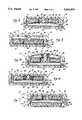
FIG. 2 is a cross-sectional view of the embodiment of FIG. 1, showing the infusion pump with a full reservoir bag installed in it;
FIG. 3 is a cross-sectional view of the first preferred embodiment, similar to that of FIG. 2, but showing the infusion pump after the reservoir bag has been substantially emptied of its contents;
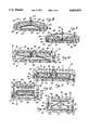
FIG. 4 is a cross-sectional view of an infusion pump in accordance with a second preferred embodiment of the invention;
FIG. 5 is graphical representation of the forces applied to the reservoir bag in the embodiment of FIG. 4;
FIG. 6 is a cross-sectional view of an infusion pump in accordance with a third preferred embodiment of the invention;
FIG. 7 is a cross-sectional view of an infusion pump in accordance with a fourth preferred embodiment of the invention;
FIG. 8 is a cross-sectional view of an infusion pump in accordance with a fifth preferred embodiment of the invention, showing the pump with a full reservoir bag installed in it;
FIG. 9 is a cross-sectional view of the fifth preferred embodiment, similar to that of FIG. 8, but showing the infusion pump after the reservoir bag has been substantially emptied of its contents;
FIG. 10 is a cross-sectional view of a modified form of the first preferred embodiment, showing the infusion pump with a full reservoir bag installed in it;
FIG. 11 is a cross-sectional view of the infusion pump of FIG. 10, but showing the pump after the reservoir bag has been substantially emptied of its contents;
FIG. 12 is a cross-sectional view of an infusion pump in accordance with a sixth preferred embodiment of the invention, showing the pump with a full reservoir bag installed in it; and
FIG. 13 is a cross-sectional view of the sixth preferred embodiment, similar to that of FIG. 12, but showing the pump after the reservoir bag has been substantially emptied of its contents.
Referring first to FIGS. 1, 2, and 3, amagnetic infusion pump 10, in accordance with a first preferred embodiment of the present invention, includes a substantially puck-shaped housing that comprises an upper orproximal housing portion 12 and a lower ordistal housing portion 14 that are removably attachable to each other to define aninternal chamber 16. (For the purpose of this specification, the terms "proximal" and "distal" are preferred and will hereinafter be used, instead of "upper" and "lower", respectively, since, as will be appreciated from the description below, the orientation of the invention in use is arbitrary.) Theproximal housing portion 12 defines a proximalinterior surface 17, and it has a distally-extending firstperipheral flange 18. Thedistal housing portion 14 defines a distalinterior surface 19, and it has a proximally-extending secondperipheral flange 20 that removably mates with thefirst flange 18 on theproximal housing portion 12. Preferably, thefirst flange 18 and thesecond flange 20 includecomplementary threads
Extending inwardly from the proximalinterior surface 17 of theproximal housing portion 12 is a substantiallycylindrical guide member 24, terminating in a distal end having a flattened, enlarged-diameter, disc-like head 26. Theguide member 24 may advantageously be removably attached to theproximal housing portion 12 by an externally-threadedend portion 28 that screws into an internally-threadedhole 30 in the center of theproximal housing portion 12. Concentrically surrounding theguide member 24 is anannular carrier 32 having acentral aperture 33 that is somewhat larger in diameter than the main portion of theguide member 24, but smaller in diameter than theguide member head 26. Thecarrier 32 has a flatdistal surface 34, to which is fixed (as by a suitable adhesive) an annularpermanent magnet 36. Themagnet 36 has a central aperture 37 (FIG. 1) that is larger in diameter than theguide member head 26. Thecarrier 32 and themagnet 36 are axially movable along theguide member 24 between a first or proximal position (FIG. 2), in which thecarrier 32 abuts against the proximalinterior surface 17 of theproximal housing portion 12, and a second or distal position (FIG. 3), in which thecarrier 32 abuts against thehead 26 of theguide member 24. In the proximal position of thecarrier 32 and themagnet 36, the distance between themagnet 36 and theplaten 40 is at its maximum, while in the distal position of thecarrier 32 and themagnet 36, the distance between themagnet 36 and theplaten 40 is at its minimum.
Thedistal housing portion 14 includes apassage 38 from theinterior chamber 16 to the exterior of the housing. Fixed to the distalinterior surface 19 of thedistal housing portion 14 is aplaten 40 of a magnetizable (ferrous) metal alloy.
The proximal and distal housing portions are separated for the installation of acollapsible reservoir bag 42, filled with a pharmacologically active liquid. When the proximal and distal housing portions are joined to each other, thebag 42 occupies the space defined between theplaten 40 and themagnet 36, with thecarrier 32 being displaced (by the bag 42) to its first or proximal position, as shown in FIG. 2. Thebag 42 includes anoutflow tube 44 that is inserted through thepassage 38.
When a completelyfull bag 42 is installed, a fraction of its surface area is in contact with themagnet 36 and theplaten 40. The magnetic attraction between theplaten 40 and themagnet 36 creates a compressive force against this contact area of thebag 42. The distance between theplaten 40 and themagnet 36 at this point is at its maximum; the magnetic force of attraction is thus at its minimum. The pressure applied to thebag 42 is equal to the magnetic force of attraction divided by the contact area.
As thebag 42 discharges its contents and deformably collapses under the pressure applied by the magnetic force of attraction, themagnet 36, carried by thecarrier 32, moves toward the second (distal) position shown in FIG. 3. As themagnet 36 moves distally, the distance between themagnet 36 and theplaten 40 decreases, thereby increasing the magnetic force of attraction. The deformable collapsing of thebag 42, however, brings more of its surface area into contact with theplaten 40 and themagnet 36. Thus, the surface area of contact increases as the magnetic force of attraction increases. Since the magnetic force of attraction is inversely proportional to the square of the distance between themagnet 36 and theplaten 40, while the rate of increase of the surface area of contact decreases as the distance decreases (up to the maximum surface area of contact, after which the surface area of contact remains constant), the compressive force applied per unit area of contact increases. As a result, the pressure applied to thebag 42 increases as thebag 42 empties, with a resultant increase in the pressure of the flow of liquid from thebag 42 through theoutflow tube 44. The rate of increase is known (e.g., empirically) for anybag 42 of a given contact aspect ratio.
A modification of the above-described embodiment is shown in FIGS. 10 and 11. In this modification, a modified platen 40' includes a central portion surrounded by a steppedperipheral portion 45, wherein the distance from the proximal surface of the steppedperipheral portion 45 to the surface of the central portion of the platen 40' (that is, the height of the stepped portion 45) is approximately equal to the thickness of a completely emptiedbag 42. With the steppedperipheral portion 45 decreasing the effective distance between the platen 40' and themagnet 36, the magnetic force of attraction is stronger, thereby increasing the compressive force (and thus the pressure) applied to the bag. This modification can be incorporated as well into the embodiments of FIGS. 4, 6, 8, and 9, described below.
FIG. 4 illustrates a magnetic infusion pump 10', in accordance with a second preferred embodiment of the invention. This embodiment is similar to the above-described first embodiment, except that a longer guide member 24' is employed, and acoil spring 46 is installed around theguide member 46, between the proximal side of thecarrier 32 and the proximal interior surface 17' of the proximal housing portion 12', which may advantageously be somewhat dome-shaped, as shown, to accommodate the longer guide member 24'.
Thespring 46 biases the carrier toward the second (distal) position, and it is at its maximum compression when thecarrier 32 is at its proximal position (shown in FIG. 4), and thus provides a greater compressive force component when the force of magnetic attraction is at its minimum. The spring component of the compressive force then decreases as the magnetic force component increases, as themagnet 36 on thecarrier 32 moves to its distal position. This embodiment, therefore, provides an augmented compressive force at the beginning of the bag discharge process, i.e., when thebag 42 is full and when it is only slightly emptied. Thus, thespring 46 compensates for the increase in the pressure applied by the magnetic force of attraction as thebag 42 is emptied. Consequently, the pressure applied to thebag 42 can be made substantially constant for bags of a given contact aspect ratio, or the pressure can be made to increase or decrease at a known rate as thebag 42 empties.
A graphic illustration of the operation of the embodiment of FIG. 4 is shown in FIG. 5, which depicts three curves of compressive force applied to thebag 42 versus volume delivered from thebag 42. Curve A represents the increase in the force of magnetic attraction as thebag 42 empties, while curve B represents the decrease in the compressive force applied by thespring 46 as thebag 42 empties. The resultant total compressive force applied to thebag 42 is represented by curve C, which shows that the total compressive force applied to thebag 42 increases slightly as thebag 42 empties. Since the surface area of contact of thebag 42 increases (at least near the beginning of the emptying process), the pressure applied to the bag 42 (and thus to the flow of liquid from it) will remain substantially constant throughout the emptying process.
Thespring 46 can be replaced to change the spring constant, and thus the slope of the curve B. Changing the slope of curve B, in turn, changes the slope of the curve C. Consequently, the pressure applied to thebag 42 can be made to remain substantially constant for bags with differing contact aspect ratios, or the pressure can be made to increase or decrease in a known, controlled manner throughout the bag emptying process.
An infusion pump 10", in accordance with a third preferred embodiment of the invention, is shown in FIG. 6. In this embodiment, anuncompressed coil spring 48 is installed around aguide member 24", spaced radially inwardly from the periphery of themagnet aperture 37. One end of thespring 48 is seated against the distal surface of thecarrier 32, and the other end of thespring 48 is seated against the proximal side of aguide member head 26". Theguide member head 26" is advantageously provided with aperipheral lip 50, which forms a seat on the proximal side of theguide member head 26" for thespring 48. With this arrangement, thespring 48 exerts a force that tends to push thecarrier 32 toward its first (proximal) position, and thus acts counter to the magnetic force of attraction. The counter-acting (proximally-directed) spring force increases as themagnet 36 and thecarrier 32 travel to the second (distal) position as thebag 42 empties. Thus, the compressive force component applied by thespring 48 decreases as the magnetic force component increases. This embodiment, therefore, provides a diminished compressive force toward the end of the bag discharge process, i.e., when thebag 42 is nearly empty. Consequently, as with the embodiment of FIG. 4, the pressure can be maintained substantially constant throughout the emptying process for bags of a given contact aspect ratio, or the pressure can be made to increase or decrease at a known rate as thebag 42 empties, depending on the spring constant.
FIG. 7 illustrates a magnetic infusion pump 10'", in accordance with a fourth preferred embodiment of the invention. In this embodiment, the platen is a fixedpermanent magnet 52, attached (as by a suitable adhesive) to the distalinterior surface 19 of thedistal housing portion 14. This double magnet embodiment provides an increased magnetic force of attraction (as compared with the above-described single magnet embodiments) throughout the bag emptying process. This embodiment may be advantageous in applications in which higher fluid pressures are desired, or where larger volume bags are used, or where bags with higher contact aspect ratios are employed.
Amagnetic infusion pump 60, in accordance with a fifth preferred embodiment of the invention, is shown in FIGS. 8 and 9. This embodiment includes aproximal housing portion 62 and adistal housing portion 64 that are removably attachable to one another, by means such asthreads 66, to form a housing that defines aninterior chamber 68. Theproximal housing portion 62 preferably has a convex, somewhat dome-shaped configuration, with acentral orifice 70. Theorifice 70 accommodates anoutflow tube 72 extending from acollapsible reservoir bag 74.
Thedistal housing portion 64 has a distalinterior surface 75, to which is fixed (as by a suitable adhesive), aplaten 76 of a magnetizable metal alloy. As illustrated, theplaten 76 may incorporate the stepped edge configuration, described above in connection with FIGS. 10 and 11, wherein theplaten 76 has acentral portion 78 and a stepped peripheral portion 79 surrounding thecentral portion 78, and extending radially inwardly from the peripheral edge of theplaten 76.
Fixed to the peripheral edge of theplaten 76, at diametrically opposite positions, are a pair of hinges 80. Eachhinge 80 has a fixed portion attached to theplaten 76, and a movable portion, to which is attached apermanent magnet 82. Themagnets 82 are thus pivotable at their hinged edges, in "drawbridge" fashion, from a first (proximal) position (FIG. 8) to a second (distal) position (FIG. 9). In the second position, themagnets 82 are more distantly spaced from thecentral portion 78 of theplaten 76 than they are from the peripheral portion 79, the spacing between themagnets 82 and thecentral portion 78 of theplaten 76 being sufficient to accommodate the thickness of the collapsedbag 74.
As compared with the single magnet embodiments described above in connection with FIGS. 1 through 4, 6, 10, and 11, this arrangement reduces the effective distance between themagnets 82 and theplaten 76, thereby increasing the magnetic force of attraction. Furthermore, as compared with the above described single magnet embodiments, a greater contact surface area between the filledbag 74 and themagnets 82 is achieved. The net result is that smaller magnets can be used to attain a desired pressure.
FIGS. 12 and 13 illustrate amagnetic infusion pump 90, in accordance with a sixth preferred embodiment of the present invention. This embodiment accommodates larger reservoir bags, that would result in such a large separation between the magnet and the platen, when the bag is filled, that the magnetic force of attraction would be too attenuated to initiate the bag discharge process.
As in the previously described embodiments, this embodiment includes a housing comprising aproximal housing portion 92, having a proximalinterior surface 93, and adistal housing portion 94, having a distalinterior surface 95. The proximal and distal housing portions are removably attached to each other, as bythreads 96. Apermanent magnet 98 is attached to the proximalinterior surface 93. Apassage 99 is formed through thedistal housing portion 94 to accommodate anoutflow tube 100 from acollapsible reservoir bag 101 that is installed in the housing so as to rest on the distalinterior surface 95.
A pivoting linkage, comprising first and secondopposed pivot arms 102, is mounted in the housing. Each of thepivot arms 102 is pivotably supported in theproximal housing portion 92 by apivot pin 104 at or near the center point of thepivot arm 102, so that thepivot arms 102, in a first position (FIG. 12), are coincident with a diameter of the housing, lying essentially parallel to themagnet 98.
The radially innermost ends of thepivot arms 102 are pivotably connected, by afirst pivot mount 106, to the center of amagnetizable metal plate 108, on its distal surface. The radially outermost end of each of thepivot arms 102 is pivotably connected, by asecond pivot mount 110, to the proximal side of apressure plate 112, each of the second pivot mounts 110 being located near diametrically opposite portions of the peripheral edge of thepressure plate 112.
When thepivot arms 102 are in the first position (FIG. 12), themagnetizable metal plate 108 is at its most distal position, at maximum distance from themagnet 98, and thepressure plate 112 is in its most proximal position, at maximum distance from the distalinterior surface 95 of thedistal housing portion 94. A filledreservoir bag 101 is placed between thepressure plate 112 and the distalinterior surface 95. The magnetic attraction between thepermanent magnet 98 and themagnetizable metal plate 108 causes themetal plate 108 to move proximally, toward a proximal position of minimum distance from themagnet 98, thereby pivoting thepivot arms 102 toward their second position (FIG. 13), in which they define a triangle with thepressure plate 112. The pivoting action of thepivot arms 102 toward their second position, in turn, forces thepressure plate 112 distally, toward a distal position of minimum distance from the distalinterior surface 95 of thedistal housing portion 94, thereby applying a pressure to thebag 101 to discharge its contents. The linkage thus allows thepressure plate 112 to travel a distance that is a multiple of the width of the magnetic gap between themetal plate 108 and themagnet 98 when the linkage is in the first position. Thus, the linkage allows the device to accommodate abag 101 which, when full, has a thickness that is as great as that multiple of the magnetic gap width.
As in the other embodiments, the magnetic force of attraction, and thus the compressive force applied to thebag 101 through the linkage, increases as the contact area to which this force is applied also increases, thereby maintaining a substantially constant pressure on thebag 101. Alternatively, the linkage can be fashioned to provide a known rate of increase in pressure.
From the foregoing description, it will be appreciated that the present invention, in its various embodiments, offers an infusion pump that is capable of providing controllable infusion pressures by means of a relatively simple magnetic and mechanical mechanism. The invention thus requires no electrical power, nor does it require electronic means for controlling its drive mechanism, and, accordingly, is relatively simple and economical to manufacture. Furthermore, the present invention is easy to use and to maintain in proper working order.
The preferred embodiments described herein are exemplary only, and further modifications and variations may suggest themselves to those skilled in the pertinent arts. For example, any of a variety of spring and/or linkage arrangements may be employed, either to accommodate reservoir bags of different sizes and configurations, or to achieve whatever compressive force-versus-volume delivered curve (FIG. 5) is desired in a particular application. Such variations and modifications should be considered within the spirit and scope of the present invention, as defined in the claims that follow.
Claims (30)
1. An infusion pump for providing a pressurized liquid flow from a collapsible, deformable, liquid-filled reservoir bag, the pump comprising:
a housing comprising first and second housing portions removably attachable to each other and defining an interior chamber sized to receive and hold a collapsible, deformable, liquid-filled reservoir bag;
a platen of magnetizable metal disposed within the housing; and
magnet means disposed within the housing for movement between a first position of maximum distance from the platen and a second position of minimum distance from the platen;
wherein a reservoir bag seated on the plate is compressed by the movement of the magnet means from the first position to the second position in response to the force of magnetic attraction between the magnet means and the platen.
2. The infusion pump of claim 1, further comprising a spring disposed between the magnet means and an interior surface of the housing so as to bias the magnet means toward the second position.
3. The infusion pump of claim 1, wherein the magnet means includes a substantially annular magnet disposed concentrically around a substantially cylindrical guide member having a first end fixed to an interior surface of the housing and a second end extending into the chamber, and wherein the infusion pump further comprises:
a spring disposed concentrically between the annular magnet and the guide member so as to bias the magnet means toward the first position.
4. The infusion pump of claim 1, wherein the platen has a peripheral edge, and wherein the magnet means comprises first and second magnets, each having a first edge that is pivotably connected to the peripheral edge of the platen, whereby the first and second magnets are pivotable at their respective first edges between the first position and the second position.
5. The infusion pump of claim 1, wherein the platen includes a magnet.
6. The infusion pump of claims 1, 2, 3, 4, or 5 wherein the platen comprises:
a central portion; and
a stepped peripheral portion surrounding the central portion, the peripheral portion being closer to the magnet means than is the central portion.
7. An infusion pump for providing a pressurized liquid flow from a collapsible, deformable, liquid-filled reservoir bag, the pump comprising:
a housing defining an interior chamber sized to receive and hold a collapsible, deformable, liquid-filled reservoir bag, the housing including a first housing portion having a proximal interior surface and a second housing portion having a distal interior surface, the first and second housing portions being removably attachable to each other;
a platen of magnetizable metal fixed to the distal interior surface; and
magnet means disposed within the housing for movement between a first position of maximum distance from the platen and a second position of minimum distance from the platen;
wherein a reservoir bag seated on the platen is compressed by the movement of the magnet means from the first position to the second position in response to the force of magnetic attraction between the magnet means and the platen.
8. The infusion pump of claim 7, further comprising a guide member extending distally into the interior chamber from the proximal interior surface, wherein the magnet means comprises:
a permanent magnet disposed on the guide member for axial translation between the first position and the second position.
9. The infusion pump of claim 8, further comprising:
a spring, disposed between the proximal interior surface and the magnet, that biases the magnet toward the second position.
10. The infusion pump of claim 7, further comprising a substantially cylindrical guide member extending distally into the interior chamber from the proximal interior surface, and having a distal end formed as an enlarged-diameter head with a proximal surface, and wherein the magnet means comprises:
a magnet carrier disposed concentrically around the guide member and having flat distal surface surrounding a central aperture that is larger than the diameter of the guide member and smaller than the diameter of the head; and
a permanent magnet fixed to the distal surface of the magnet carrier and having a central aperture with a diameter that is larger than the diameter of the head.
11. The infusion pump of claim 10, further comprising:
a spring disposed concentrically around the guide member and seated between the distal surface of the magnet carrier and the proximal surface of the head, so that the spring biases the carrier toward the first position.
12. The infusion pump of claim 7, wherein the platen includes a permanent magnet.
13. The infusion pump of claim 7, wherein the platen has a peripheral edge, and wherein the magnet means comprises first and second magnets, each having a first edge that is pivotably connected to the peripheral edge of the platen, whereby the first and second magnets are pivotable at their respective first edges between the first position and the second position.
14. The infusion pump of claims 7, 8, 9, 10, 11, 12, or 13, wherein the platen comprises:
a central portion; and
a stepped peripheral portion surrounding the central portion, the peripheral portion being closer to the magnet means than is the central portion.
15. An infusion pump for providing a pressurized liquid flow from a collapsible, deformable, liquid-filled reservoir bag, the pump comprising:
a housing defining an interior chamber sized to receive and hold a collapsible, deformable, liquid-filled reservoir bag, the housing including a first housing portion having a proximal interior surface and a second housing portion having a distal interior surface, the first and second housing portions being removably attachable to each other;
a pressure plate disposed within the housing and movable between a first position of maximum distance from the distal interior surface and a second position of minimum distance from the distal interior surface; and
magnetic means, disposed within the housing, for moving the pressure plate between the first and second positions by the force of magnetic attraction;
whereby a reservoir bag disposed within the housing between the pressure plate and the distal interior surface is compressed by the movement of the pressure plate from the first position to the second position.
16. The infusion pump of claim 15, wherein the magnetic means comprises:
a permanent magnet fixed to the proximal interior surface;
a magnetizable metal plate disposed between the magnet and the pressure plate and movable between a distal position of maximum distance from the magnet and a proximal position of minimum distance from the magnet; and
a pivoting linkage connecting the magnetizable metal plate and the pressure plate so that the movement of the magnetizable metal plate from the distal position to the proximal position in response to the force of magnetic attraction causes the pressure plate to move from the first position to the second position.
17. The infusion pump of claim 16, wherein pressure plate has a peripheral edge, and wherein the pivoting linkage comprises:
first and second opposed pivot arms, each having a radially innermost end and a radially outermost end, each of the pivot arms being pivotably supported near its center point within the housing;
first pivot means pivotably connecting the radially innermost end of each of the pivot arms to the approximate center of the magnetizable metal plate; and
second pivot means pivotably connecting the radially outermost end of each of the pivot arms to pressure plate near diametrically opposite portions of its peripheral edge;
wherein the pivot arms are movable between a first position, in which they lie substantially parallel with the magnet, and a second position, in which they define a triangle with the pressure plate, the first position of the pivot arms coinciding with the first position of the pressure plate and the distal position of the magnetizable metal plate, and the second position of the pivot arms coinciding with the second position of the pressure plate and the proximal position of the magnetizable metal plate.
18. An infusion pump for providing a pressurized liquid flow from a collapsible, deformable, liquid-filled reservoir bag, the pump comprising:
a housing defining an interior chamber sized to receive and hold a collapsible, deformable, liquid-filled reservoir bag, the housing including a first housing portion having a proximal interior surface and a second housing portion having a distal interior surface, the first and second housing portions being removably attachable to each other;
a platen of magnetizable metal fixed to the distal interior surface and having a peripheral edge; and
first and second magnets disposed within the housing for movement between a first position of maximum distance from the platen and a second position of minimum distance from the platen, each of the magnets having a pivoting edge that is pivotably connected to the peripheral edge of the platen, whereby the first and second magnets are pivotable at their respective pivoting edges between the first position and the second position;
wherein a reservoir bag seated on the platen is compressed by the movement of the first and second magnets from the first position to the second position in response to the force of magnetic attraction between the first and second magnets and the platen.
19. The infusion pump of claim 18, wherein the platen has first and second diametrically-opposed edge portions, and wherein the first magnet is pivotably connected to the first edge portion and the second magnet is pivotably connected to the second edge portion.
20. The infusion pump of claim 1, further comprising:
a first hinge having a fixed portion attached to the first edge portion, and a movable portion attached to the pivoting edge of the first magnet; and
a second hinge having a fixed portion attached to the second edge portion, and a movable portion attached to the pivoting edge of the second magnet.
21. The infusion pump of claims 18, 19, or 20, wherein the platen comprises:
a central portion; and
a stepped peripheral portion surrounding the central portion, the peripheral portion extending radially inwardly from the peripheral edge, whereby the central portion is more distantly spaced from the first and second magnets than is the peripheral portion when the first and second magnets are in their second position.
22. An infusion pump for providing a pressurized liquid flow from a collapsible, deformable, liquid-filled reservoir bag, the pump comprising:
a housing defining an interior chamber sized to receive and hold a collapsible, deformable, liquid-filled reservoir bag, the housing including a first housing portion having a proximal interior surface and a second housing portion having a distal interior surface, the first and second housing portions being removably attachable to each other;
a platen of magnetizable metal fixed to the distal interior surface;
a guide member extending distally into the interior chamber from the proximal interior surface, and having a distal end;
a magnet disposed on the guide member for axial translation between a first position of maximum distance from the platen and a second position of minimum distance from the platen; and
a spring, disposed between the proximal interior surface and the magnet, that biases the magnet toward the second position.
23. The infusion pump of claim 22, further comprising:
an enlarged-diameter head formed on the distal end of the guide member, the head having a proximal surface; and
a magnet carrier disposed concentrically around the guide member and having flat distal surface surrounding a central aperture that is larger than the diameter of the guide member and smaller than the diameter of the head, wherein the magnet is fixed to the distal surface of the magnet carrier and has a central aperture with a diameter that is larger than the diameter of the head.
24. The infusion pump of claim 23, wherein the spring is disposed concentrically around the guide member and is seated between the magnet carrier and the proximal interior surface of the first housing portion, so that the spring biases the carrier toward the second position.
25. The infusion pump of claims 22, 23, or 24, wherein the platen includes a permanent magnet.
26. The infusion pump of claims 22, 23, or 24, wherein the platen comprises:
a central portion; and
a stepped peripheral portion surrounding the central portion, the peripheral portion being closer to the magnet than is the central portion.
27. The infusion pump of claim 26, wherein the platen includes a permanent magnet.
28. An infusion pump for providing a pressurized liquid flow from a collapsible, deformable, liquid-filled reservoir bag, the pump comprising:
a housing defining an interior chamber sized to receive and hold a collapsible, deformable, liquid-filled reservoir bag, the housing including a first housing portion having a proximal interior surface and a second housing portion having a distal interior surface, the first and second housing portions being removably attachable to each other;
a platen of magnetizable metal fixed to the distal interior surface;
a guide member extending distally into the interior chamber from the proximal interior surface, and having a distal end formed as an enlarged-diameter head with a proximal surface;
a magnet carrier disposed concentrically around the guide member and having flat distal surface surrounding a central aperture that is larger than the diameter of the guide member and smaller than the diameter of the head, the magnet carrier being axially movable on the guide member between a first position of maximum distance from the platen and a second position of minimum distance from the platen;
a magnet fixed to the distal surface of the magnet carrier and having a central aperture with a diameter that is larger than the diameter of the head; and
a spring, disposed concentrically around the guide member and seated between the distal surface of the magnet carrier and the proximal surface of the head, that biases the magnet toward the first position.
29. The infusion pump of claim 28, wherein the platen comprises:
a central portion; and
a stepped peripheral portion surrounding the central portion, the peripheral portion being closer to the magnet than is the central portion.
30. The infusion pump of claim 28, or 29, wherein the platen includes a permanent magnet.
Priority Applications (1)
| Application Number | Priority Date | Filing Date | Title |
|---|---|---|---|
| US08/374,877US5665070A (en) | 1995-01-19 | 1995-01-19 | Infusion pump with magnetic bag compression |
Applications Claiming Priority (1)
| Application Number | Priority Date | Filing Date | Title |
|---|---|---|---|
| US08/374,877US5665070A (en) | 1995-01-19 | 1995-01-19 | Infusion pump with magnetic bag compression |
Publications (1)
| Publication Number | Publication Date |
|---|---|
| US5665070Atrue US5665070A (en) | 1997-09-09 |
Family
ID=23478552
Family Applications (1)
| Application Number | Title | Priority Date | Filing Date |
|---|---|---|---|
| US08/374,877Expired - LifetimeUS5665070A (en) | 1995-01-19 | 1995-01-19 | Infusion pump with magnetic bag compression |
Country Status (1)
| Country | Link |
|---|---|
| US (1) | US5665070A (en) |
Cited By (138)
| Publication number | Priority date | Publication date | Assignee | Title |
|---|---|---|---|---|
| US6032665A (en)* | 1996-05-06 | 2000-03-07 | Siemens Elema Ab | Dosing device for adding an additive fluid to breathing gas in an anaesthesia machine or ventilator |
| WO2000037126A1 (en)* | 1998-12-18 | 2000-06-29 | Berlin Heart Ag | Pulsatile pump |
| US6228050B1 (en)* | 1999-04-30 | 2001-05-08 | Medtronic Inc. | Overfill protection systems for implantable drug delivery devices |
| US6251098B1 (en)* | 1992-01-24 | 2001-06-26 | I-Flow, Corp. | Fluid container for use with platen pump |
| US20020058332A1 (en)* | 2000-09-15 | 2002-05-16 | California Institute Of Technology | Microfabricated crossflow devices and methods |
| US20020109114A1 (en)* | 2000-11-06 | 2002-08-15 | California Institute Of Technology | Electrostatic valves for microfluidic devices |
| US6485461B1 (en)* | 2000-04-04 | 2002-11-26 | Insulet, Inc. | Disposable infusion device |
| US6656159B2 (en) | 2002-04-23 | 2003-12-02 | Insulet Corporation | Dispenser for patient infusion device |
| US6656158B2 (en) | 2002-04-23 | 2003-12-02 | Insulet Corporation | Dispenser for patient infusion device |
| US6669669B2 (en) | 2001-10-12 | 2003-12-30 | Insulet Corporation | Laminated patient infusion device |
| US20040015131A1 (en)* | 2002-07-16 | 2004-01-22 | Flaherty J. Christopher | Flow restriction system and method for patient infusion device |
| US20040027083A1 (en)* | 2002-04-26 | 2004-02-12 | Toyoda Koki Kabushiki Kaisha | Motor control device |
| US6692457B2 (en) | 2002-03-01 | 2004-02-17 | Insulet Corporation | Flow condition sensor assembly for patient infusion device |
| US6699218B2 (en) | 2000-11-09 | 2004-03-02 | Insulet Corporation | Transcutaneous delivery means |
| US20040072278A1 (en)* | 2002-04-01 | 2004-04-15 | Fluidigm Corporation | Microfluidic particle-analysis systems |
| US6723072B2 (en) | 2002-06-06 | 2004-04-20 | Insulet Corporation | Plunger assembly for patient infusion device |
| US20040087894A1 (en)* | 2000-09-08 | 2004-05-06 | Flaherty J. Christopher | Devices, systems and methods for patient infusion |
| US6749587B2 (en) | 2001-02-22 | 2004-06-15 | Insulet Corporation | Modular infusion device and method |
| US6768425B2 (en) | 2000-12-21 | 2004-07-27 | Insulet Corporation | Medical apparatus remote control and method |
| US6830558B2 (en) | 2002-03-01 | 2004-12-14 | Insulet Corporation | Flow condition sensor assembly for patient infusion device |
| US20050005710A1 (en)* | 2002-05-15 | 2005-01-13 | Therafuse, Inc. | Liquid metering system |
| US20050050941A1 (en)* | 2002-05-15 | 2005-03-10 | Sage Burton H. | Liquid measuring system |
| US20050059926A1 (en)* | 2003-09-16 | 2005-03-17 | Therafuse, Inc. | Compensating liquid delivery system and method |
| US20050084421A1 (en)* | 2003-04-03 | 2005-04-21 | Fluidigm Corporation | Microfluidic devices and methods of using same |
| US20050098568A1 (en)* | 2003-11-06 | 2005-05-12 | Chang-Keng Tsai | Double-layered fluid container |
| US20050145496A1 (en)* | 2003-04-03 | 2005-07-07 | Federico Goodsaid | Thermal reaction device and method for using the same |
| US20050197652A1 (en)* | 2002-05-13 | 2005-09-08 | Fluidigm Corporation | Drug delivery system |
| US20050238506A1 (en)* | 2002-06-21 | 2005-10-27 | The Charles Stark Draper Laboratory, Inc. | Electromagnetically-actuated microfluidic flow regulators and related applications |
| US6960192B1 (en) | 2002-04-23 | 2005-11-01 | Insulet Corporation | Transcutaneous fluid delivery system |
| WO2003082371A3 (en)* | 2002-03-26 | 2006-02-02 | Becton Dickinson Co | Multi-stage fluid delivery device and method |
| US20060036416A1 (en)* | 2000-06-27 | 2006-02-16 | Fluidigm Corporation | Computer aided design method and system for developing a microfluidic system |
| FR2876589A1 (en) | 2004-10-14 | 2006-04-21 | Vygon Sa | Device for emptying a pocket having analgesic comprises two superimposed rooms with identical capacities and double piston, one room has pocket and the other constitutes a vacuum chamber, and both piston heads are solidarized by a stem |
| US20060089620A1 (en)* | 2003-06-25 | 2006-04-27 | Gibson Scott R | Medication infusion device using negatively biased ambient pressure medication chamber |
| US20060118895A1 (en)* | 2001-08-30 | 2006-06-08 | Fluidigm Corporation | Electrostatic/electrostrictive actuation of elastomer structures using compliant electrodes |
| US20060233648A1 (en)* | 2003-01-28 | 2006-10-19 | Chengxun Liu | Method for fluid transfer and the micro peristaltic pump |
| US7128727B2 (en) | 2002-09-30 | 2006-10-31 | Flaherty J Christopher | Components and methods for patient infusion device |
| US7144384B2 (en) | 2002-09-30 | 2006-12-05 | Insulet Corporation | Dispenser components and methods for patient infusion device |
| US20070005044A1 (en)* | 2005-05-10 | 2007-01-04 | Palion Medical Corporation | Implantable pump with infinitely variable resistor |
| US7192629B2 (en) | 2001-10-11 | 2007-03-20 | California Institute Of Technology | Devices utilizing self-assembled gel and method of manufacture |
| US20070112328A1 (en)* | 2005-05-10 | 2007-05-17 | Palyon Medical Corporation | Variable flow infusion pump system |
| US20070255260A1 (en)* | 2006-04-27 | 2007-11-01 | Haase James M | Infusion device and pressure-based overfill protection mechanism for use with same |
| US20070278140A1 (en)* | 2003-09-19 | 2007-12-06 | Vesta Medical, Llc | Restricted access waste sorting system |
| US20070293979A1 (en)* | 2003-09-19 | 2007-12-20 | Vesta Medical, Llc | Method of sorting composite drugs |
| US20080015494A1 (en)* | 2006-07-11 | 2008-01-17 | Microchips, Inc. | Multi-reservoir pump device for dialysis, biosensing, or delivery of substances |
| US20080097319A1 (en)* | 2006-09-18 | 2008-04-24 | National Defense Medical Center | Active squeezing device for a drip bag |
| US7413712B2 (en) | 2003-08-11 | 2008-08-19 | California Institute Of Technology | Microfluidic rotary flow reactor matrix |
| US20080215029A1 (en)* | 1993-01-22 | 2008-09-04 | I-Flow Corporation | Platen pump |
| US20080249510A1 (en)* | 2007-01-31 | 2008-10-09 | Mescher Mark J | Membrane-based fluid control in microfluidic devices |
| US7442556B2 (en) | 2000-10-13 | 2008-10-28 | Fluidigm Corporation | Microfluidic-based electrospray source for analytical devices with a rotary fluid flow channel for sample preparation |
| US7487100B2 (en) | 2003-09-19 | 2009-02-03 | Vesta Medical, Llc | Method of sorting regulated drug waste |
| US20090101550A1 (en)* | 2007-10-22 | 2009-04-23 | Baxter International Inc. | Dialysis system having non-invasive fluid velocity sensing |
| US7530968B2 (en) | 2003-04-23 | 2009-05-12 | Valeritas, Inc. | Hydraulically actuated pump for long duration medicament administration |
| US20090237884A1 (en)* | 2005-12-30 | 2009-09-24 | Intel Corporation | Electromagnetically-actuated micropump for liquid metal alloy |
| US20090299545A1 (en)* | 2003-05-20 | 2009-12-03 | Fluidigm Corporation | Method and system for microfluidic device and imaging thereof |
| US7660724B2 (en) | 2003-09-19 | 2010-02-09 | Vesta Medical, Llc | Waste sorting system utilizing removable liners |
| US7666361B2 (en) | 2003-04-03 | 2010-02-23 | Fluidigm Corporation | Microfluidic devices and methods of using same |
| US7691333B2 (en) | 2001-11-30 | 2010-04-06 | Fluidigm Corporation | Microfluidic device and methods of using same |
| US20100119154A1 (en)* | 2003-07-28 | 2010-05-13 | Fluidigm Corporation | Image processing method and system for microfluidic devices |
| US7749737B2 (en) | 2003-04-03 | 2010-07-06 | Fluidigm Corporation | Thermal reaction device and method for using the same |
| US7820427B2 (en) | 2001-11-30 | 2010-10-26 | Fluidigm Corporation | Microfluidic device and methods of using same |
| US7833708B2 (en) | 2001-04-06 | 2010-11-16 | California Institute Of Technology | Nucleic acid amplification using microfluidic devices |
| US7914499B2 (en) | 2006-03-30 | 2011-03-29 | Valeritas, Inc. | Multi-cartridge fluid delivery device |
| US20110196304A1 (en)* | 2009-12-26 | 2011-08-11 | The Board Of Regents Of The University Of Texas System | Fluid Balance Monitoring System with Fluid Infusion Pump for Medical Treatment |
| US8105269B2 (en) | 2008-10-24 | 2012-01-31 | Baxter International Inc. | In situ tubing measurements for infusion pumps |
| US8114055B2 (en) | 2005-05-10 | 2012-02-14 | Palyon Medical (Bvi) Limited | Implantable pump with infinitely variable resistor |
| US8137083B2 (en) | 2009-03-11 | 2012-03-20 | Baxter International Inc. | Infusion pump actuators, system and method for controlling medical fluid flowrate |
| WO2012027295A3 (en)* | 2010-08-26 | 2012-05-18 | Carefusion 303, Inc. | Pumping system with magnetic material |
| US8195328B2 (en) | 2003-09-19 | 2012-06-05 | Vesta Medical, Llc | Combination disposal and dispensing apparatus and method |
| US8197235B2 (en) | 2009-02-18 | 2012-06-12 | Davis David L | Infusion pump with integrated permanent magnet |
| US8202267B2 (en) | 2006-10-10 | 2012-06-19 | Medsolve Technologies, Inc. | Method and apparatus for infusing liquid to a body |
| US8287495B2 (en) | 2009-07-30 | 2012-10-16 | Tandem Diabetes Care, Inc. | Infusion pump system with disposable cartridge having pressure venting and pressure feedback |
| US8353864B2 (en) | 2009-02-18 | 2013-01-15 | Davis David L | Low cost disposable infusion pump |
| US8382447B2 (en) | 2009-12-31 | 2013-02-26 | Baxter International, Inc. | Shuttle pump with controlled geometry |
| US8408421B2 (en) | 2008-09-16 | 2013-04-02 | Tandem Diabetes Care, Inc. | Flow regulating stopcocks and related methods |
| US8440093B1 (en) | 2001-10-26 | 2013-05-14 | Fuidigm Corporation | Methods and devices for electronic and magnetic sensing of the contents of microfluidic flow channels |
| US8568360B2 (en) | 2011-12-28 | 2013-10-29 | Palyon Medical (Bvi) Limited | Programmable implantable pump design |
| US8567235B2 (en) | 2010-06-29 | 2013-10-29 | Baxter International Inc. | Tube measurement technique using linear actuator and pressure sensor |
| US8650937B2 (en) | 2008-09-19 | 2014-02-18 | Tandem Diabetes Care, Inc. | Solute concentration measurement device and related methods |
| US8658418B2 (en) | 2002-04-01 | 2014-02-25 | Fluidigm Corporation | Microfluidic particle-analysis systems |
| US8708961B2 (en) | 2008-01-28 | 2014-04-29 | Medsolve Technologies, Inc. | Apparatus for infusing liquid to a body |
| US8828663B2 (en) | 2005-03-18 | 2014-09-09 | Fluidigm Corporation | Thermal reaction device and method for using the same |
| JP2014180447A (en)* | 2013-03-19 | 2014-09-29 | Aquatech Co Ltd | Micropump |
| US8871446B2 (en) | 2002-10-02 | 2014-10-28 | California Institute Of Technology | Microfluidic nucleic acid analysis |
| US8876795B2 (en) | 2011-02-02 | 2014-11-04 | The Charles Stark Draper Laboratory, Inc. | Drug delivery apparatus |
| JP2014210004A (en)* | 2013-04-18 | 2014-11-13 | ニプロ株式会社 | Subcutaneously implanting-type port |
| US8915893B2 (en) | 2005-05-10 | 2014-12-23 | Palyon Medical (Bvi) Limited | Variable flow infusion pump system |
| US8986253B2 (en) | 2008-01-25 | 2015-03-24 | Tandem Diabetes Care, Inc. | Two chamber pumps and related methods |
| US9089636B2 (en) | 2004-07-02 | 2015-07-28 | Valeritas, Inc. | Methods and devices for delivering GLP-1 and uses thereof |
| US9180054B2 (en) | 2004-01-29 | 2015-11-10 | The Charles Stark Draper Laboratory, Inc. | Drug delivery apparatus |
| US9714443B2 (en) | 2002-09-25 | 2017-07-25 | California Institute Of Technology | Microfabricated structure having parallel and orthogonal flow channels controlled by row and column multiplexors |
| US20170259228A1 (en)* | 2014-03-17 | 2017-09-14 | Advanced Scientifics, Inc. | Transportable mixing system for biological and pharmaceutical materials |
| EP3302599A1 (en)* | 2015-06-02 | 2018-04-11 | Primed Halberstadt Medizintechnik GmbH | Device for drainage, in particular for drainage of a chronic subdural hematoma |
| US9962486B2 (en) | 2013-03-14 | 2018-05-08 | Tandem Diabetes Care, Inc. | System and method for detecting occlusions in an infusion pump |
| US10015931B2 (en) | 2012-12-28 | 2018-07-10 | Elwha Llc | Production of electricity from plants |
| US10015971B2 (en) | 2012-12-28 | 2018-07-10 | Elwha Llc | Articles and methods for administering CO2 into plants |
| US10017392B2 (en) | 2012-12-28 | 2018-07-10 | Elwha Llc | Articles and methods for administering CO2 into plants |
| US10258736B2 (en) | 2012-05-17 | 2019-04-16 | Tandem Diabetes Care, Inc. | Systems including vial adapter for fluid transfer |
| US10342926B2 (en) | 2016-05-26 | 2019-07-09 | Insulet Corporation | Single dose drug delivery device |
| US10363372B2 (en) | 2016-08-12 | 2019-07-30 | Insulet Corporation | Plunger for drug delivery device |
| US10441723B2 (en) | 2016-08-14 | 2019-10-15 | Insulet Corporation | Variable fill drug delivery device |
| US10603440B2 (en) | 2017-01-19 | 2020-03-31 | Insulet Corporation | Cartridge hold-up volume reduction |
| US10695485B2 (en) | 2017-03-07 | 2020-06-30 | Insulet Corporation | Very high volume user filled drug delivery device |
| US10751478B2 (en) | 2016-10-07 | 2020-08-25 | Insulet Corporation | Multi-stage delivery system |
| US10780217B2 (en) | 2016-11-10 | 2020-09-22 | Insulet Corporation | Ratchet drive for on body delivery system |
| US10874803B2 (en) | 2018-05-31 | 2020-12-29 | Insulet Corporation | Drug cartridge with drive system |
| US10898656B2 (en) | 2017-09-26 | 2021-01-26 | Insulet Corporation | Needle mechanism module for drug delivery device |
| US10973978B2 (en) | 2017-08-03 | 2021-04-13 | Insulet Corporation | Fluid flow regulation arrangements for drug delivery devices |
| US20210128823A1 (en)* | 2017-08-22 | 2021-05-06 | Steadymed, Ltd. | Selectively mechanically activatable prefilled infusion-pump devices |
| US11045603B2 (en) | 2017-02-22 | 2021-06-29 | Insulet Corporation | Needle insertion mechanisms for drug containers |
| US11090434B2 (en) | 2015-11-24 | 2021-08-17 | Insulet Corporation | Automated drug delivery system |
| US11147931B2 (en) | 2017-11-17 | 2021-10-19 | Insulet Corporation | Drug delivery device with air and backflow elimination |
| US11229736B2 (en) | 2018-06-06 | 2022-01-25 | Insulet Corporation | Linear shuttle pump for drug delivery |
| US11229741B2 (en) | 2012-03-30 | 2022-01-25 | Insulet Corporation | Fluid delivery device, transcutaneous access tool and fluid drive mechanism for use therewith |
| US11280327B2 (en) | 2017-08-03 | 2022-03-22 | Insulet Corporation | Micro piston pump |
| US11364341B2 (en) | 2015-11-25 | 2022-06-21 | Insulet Corporation | Wearable medication delivery device |
| US20220193334A1 (en)* | 2016-09-27 | 2022-06-23 | Sanofi-Aventis Deutschland Gmbh | Medicament delivery device |
| US11369735B2 (en) | 2019-11-05 | 2022-06-28 | Insulet Corporation | Component positioning of a linear shuttle pump |
| US11446435B2 (en) | 2018-11-28 | 2022-09-20 | Insulet Corporation | Drug delivery shuttle pump system and valve assembly |
| US11786668B2 (en) | 2017-09-25 | 2023-10-17 | Insulet Corporation | Drug delivery devices, systems, and methods with force transfer elements |
| US11857763B2 (en) | 2016-01-14 | 2024-01-02 | Insulet Corporation | Adjusting insulin delivery rates |
| US11865299B2 (en) | 2008-08-20 | 2024-01-09 | Insulet Corporation | Infusion pump systems and methods |
| US11929158B2 (en) | 2016-01-13 | 2024-03-12 | Insulet Corporation | User interface for diabetes management system |
| USD1020794S1 (en) | 2018-04-02 | 2024-04-02 | Bigfoot Biomedical, Inc. | Medication delivery device with icons |
| USD1024090S1 (en) | 2019-01-09 | 2024-04-23 | Bigfoot Biomedical, Inc. | Display screen or portion thereof with graphical user interface associated with insulin delivery |
| US11969579B2 (en) | 2017-01-13 | 2024-04-30 | Insulet Corporation | Insulin delivery methods, systems and devices |
| US12042630B2 (en) | 2017-01-13 | 2024-07-23 | Insulet Corporation | System and method for adjusting insulin delivery |
| US12064591B2 (en) | 2013-07-19 | 2024-08-20 | Insulet Corporation | Infusion pump system and method |
| US12076160B2 (en) | 2016-12-12 | 2024-09-03 | Insulet Corporation | Alarms and alerts for medication delivery devices and systems |
| US12097355B2 (en) | 2023-01-06 | 2024-09-24 | Insulet Corporation | Automatically or manually initiated meal bolus delivery with subsequent automatic safety constraint relaxation |
| US12106837B2 (en) | 2016-01-14 | 2024-10-01 | Insulet Corporation | Occlusion resolution in medication delivery devices, systems, and methods |
| US12146585B2 (en)* | 2020-10-08 | 2024-11-19 | I Peace, Inc. | Pinch valve actuated by non-contact force |
| US12318577B2 (en) | 2017-01-13 | 2025-06-03 | Insulet Corporation | System and method for adjusting insulin delivery |
| US12343502B2 (en) | 2017-01-13 | 2025-07-01 | Insulet Corporation | System and method for adjusting insulin delivery |
| US12359903B2 (en) | 2021-05-28 | 2025-07-15 | Insulet Corporation | Spring-based status sensors |
| US12377208B2 (en) | 2021-01-08 | 2025-08-05 | Insulet Corporation | Single actuated precision dose intermediate pumping chamber |
| US12383166B2 (en) | 2016-05-23 | 2025-08-12 | Insulet Corporation | Insulin delivery system and methods with risk-based set points |
| US12433512B2 (en) | 2020-12-18 | 2025-10-07 | Insulet Corporation | Adhesive pad with a metallic coil for securing an on-body medical device |
| US12440617B2 (en) | 2022-01-05 | 2025-10-14 | Insulet Corporation | Linear activated drug dosing pump system |
Citations (19)
| Publication number | Priority date | Publication date | Assignee | Title |
|---|---|---|---|---|
| US119996A (en)* | 1871-10-17 | Improvement in electro-magnetic water-elevators | ||
| US1425191A (en)* | 1919-12-26 | 1922-08-08 | Garbarini Andre | Pumping apparatus |
| US2240307A (en)* | 1937-07-06 | 1941-04-29 | List Heinrich | Fluid pump |
| US2849159A (en)* | 1955-07-18 | 1958-08-26 | Marshfield Mfg Company | Solenoid-actuated dispenser |
| US3768931A (en)* | 1971-05-03 | 1973-10-30 | Birch R | Magnetically actuated pump with flexible membrane |
| US3842440A (en)* | 1972-09-01 | 1974-10-22 | E Karlson | Implantable linear motor prosthetic heart and control system therefor |
| US4274407A (en)* | 1979-11-13 | 1981-06-23 | Med Pump, Inc. | Fluid injection system |
| US4302854A (en)* | 1980-06-04 | 1981-12-01 | Runge Thomas M | Electrically activated ferromagnetic/diamagnetic vascular shunt for left ventricular assist |
| US4360019A (en)* | 1979-02-28 | 1982-11-23 | Andros Incorporated | Implantable infusion device |
| US4444548A (en)* | 1980-08-08 | 1984-04-24 | University Testing Service Inc. | Suction apparatus |
| US4447232A (en)* | 1982-05-21 | 1984-05-08 | Repro-Med Systems, Inc. | Spring-operated liquid-dispensing device |
| US4488099A (en)* | 1982-12-03 | 1984-12-11 | Novacor Medical Corporation | Real time servo control apparatus and method |
| US4557726A (en)* | 1982-12-27 | 1985-12-10 | Consolidated Controls Corporation | Precision medication dispensing system and method |
| US4594058A (en)* | 1984-06-01 | 1986-06-10 | The Johns Hopkins University | Single valve diaphragm pump with decreased sensitivity to ambient conditions |
| US4907723A (en)* | 1986-03-10 | 1990-03-13 | Solly Katz | Fluid dispenser including an arrangement to impart wave-like motion to the store fluid |
| US5232439A (en)* | 1992-11-02 | 1993-08-03 | Infusion Technologies Corporation | Method for pumping fluid from a flexible, variable geometry reservoir |
| US5242406A (en)* | 1990-10-19 | 1993-09-07 | Sil Medics Ltd. | Liquid delivery device particularly useful for delivering drugs |
| US5328477A (en)* | 1993-06-21 | 1994-07-12 | Sitko Phillip M | Liquid infusion system |
| US5330431A (en)* | 1993-03-12 | 1994-07-19 | Glenn Herskowitz | Infusion pump |
- 1995
- 1995-01-19USUS08/374,877patent/US5665070A/ennot_activeExpired - Lifetime
Patent Citations (19)
| Publication number | Priority date | Publication date | Assignee | Title |
|---|---|---|---|---|
| US119996A (en)* | 1871-10-17 | Improvement in electro-magnetic water-elevators | ||
| US1425191A (en)* | 1919-12-26 | 1922-08-08 | Garbarini Andre | Pumping apparatus |
| US2240307A (en)* | 1937-07-06 | 1941-04-29 | List Heinrich | Fluid pump |
| US2849159A (en)* | 1955-07-18 | 1958-08-26 | Marshfield Mfg Company | Solenoid-actuated dispenser |
| US3768931A (en)* | 1971-05-03 | 1973-10-30 | Birch R | Magnetically actuated pump with flexible membrane |
| US3842440A (en)* | 1972-09-01 | 1974-10-22 | E Karlson | Implantable linear motor prosthetic heart and control system therefor |
| US4360019A (en)* | 1979-02-28 | 1982-11-23 | Andros Incorporated | Implantable infusion device |
| US4274407A (en)* | 1979-11-13 | 1981-06-23 | Med Pump, Inc. | Fluid injection system |
| US4302854A (en)* | 1980-06-04 | 1981-12-01 | Runge Thomas M | Electrically activated ferromagnetic/diamagnetic vascular shunt for left ventricular assist |
| US4444548A (en)* | 1980-08-08 | 1984-04-24 | University Testing Service Inc. | Suction apparatus |
| US4447232A (en)* | 1982-05-21 | 1984-05-08 | Repro-Med Systems, Inc. | Spring-operated liquid-dispensing device |
| US4488099A (en)* | 1982-12-03 | 1984-12-11 | Novacor Medical Corporation | Real time servo control apparatus and method |
| US4557726A (en)* | 1982-12-27 | 1985-12-10 | Consolidated Controls Corporation | Precision medication dispensing system and method |
| US4594058A (en)* | 1984-06-01 | 1986-06-10 | The Johns Hopkins University | Single valve diaphragm pump with decreased sensitivity to ambient conditions |
| US4907723A (en)* | 1986-03-10 | 1990-03-13 | Solly Katz | Fluid dispenser including an arrangement to impart wave-like motion to the store fluid |
| US5242406A (en)* | 1990-10-19 | 1993-09-07 | Sil Medics Ltd. | Liquid delivery device particularly useful for delivering drugs |
| US5232439A (en)* | 1992-11-02 | 1993-08-03 | Infusion Technologies Corporation | Method for pumping fluid from a flexible, variable geometry reservoir |
| US5330431A (en)* | 1993-03-12 | 1994-07-19 | Glenn Herskowitz | Infusion pump |
| US5328477A (en)* | 1993-06-21 | 1994-07-12 | Sitko Phillip M | Liquid infusion system |
Cited By (263)
| Publication number | Priority date | Publication date | Assignee | Title |
|---|---|---|---|---|
| US6251098B1 (en)* | 1992-01-24 | 2001-06-26 | I-Flow, Corp. | Fluid container for use with platen pump |
| US7337922B2 (en)* | 1992-01-24 | 2008-03-04 | I-Flow Corporation | Platen pump |
| US20080215029A1 (en)* | 1993-01-22 | 2008-09-04 | I-Flow Corporation | Platen pump |
| US6032665A (en)* | 1996-05-06 | 2000-03-07 | Siemens Elema Ab | Dosing device for adding an additive fluid to breathing gas in an anaesthesia machine or ventilator |
| RU2211709C2 (en)* | 1998-12-18 | 2003-09-10 | Берлин Харт Аг | Pulsation pump |
| WO2000037126A1 (en)* | 1998-12-18 | 2000-06-29 | Berlin Heart Ag | Pulsatile pump |
| US6228050B1 (en)* | 1999-04-30 | 2001-05-08 | Medtronic Inc. | Overfill protection systems for implantable drug delivery devices |
| US6485461B1 (en)* | 2000-04-04 | 2002-11-26 | Insulet, Inc. | Disposable infusion device |
| US7526741B2 (en) | 2000-06-27 | 2009-04-28 | Fluidigm Corporation | Microfluidic design automation method and system |
| US9926521B2 (en) | 2000-06-27 | 2018-03-27 | Fluidigm Corporation | Microfluidic particle-analysis systems |
| US20060036416A1 (en)* | 2000-06-27 | 2006-02-16 | Fluidigm Corporation | Computer aided design method and system for developing a microfluidic system |
| US20040087894A1 (en)* | 2000-09-08 | 2004-05-06 | Flaherty J. Christopher | Devices, systems and methods for patient infusion |
| US7029455B2 (en) | 2000-09-08 | 2006-04-18 | Insulet Corporation | Devices, systems and methods for patient infusion |
| US7137964B2 (en) | 2000-09-08 | 2006-11-21 | Insulet Corporation | Devices, systems and methods for patient infusion |
| US8658368B2 (en) | 2000-09-15 | 2014-02-25 | California Institute Of Technology | Microfabricated crossflow devices and methods |
| US20020058332A1 (en)* | 2000-09-15 | 2002-05-16 | California Institute Of Technology | Microfabricated crossflow devices and methods |
| US7294503B2 (en) | 2000-09-15 | 2007-11-13 | California Institute Of Technology | Microfabricated crossflow devices and methods |
| US8252539B2 (en) | 2000-09-15 | 2012-08-28 | California Institute Of Technology | Microfabricated crossflow devices and methods |
| US8592215B2 (en) | 2000-09-15 | 2013-11-26 | California Institute Of Technology | Microfabricated crossflow devices and methods |
| US20090035838A1 (en)* | 2000-09-15 | 2009-02-05 | California Institute Of Technology | Microfabricated Crossflow Devices and Methods |
| US8445210B2 (en) | 2000-09-15 | 2013-05-21 | California Institute Of Technology | Microfabricated crossflow devices and methods |
| US8658367B2 (en) | 2000-09-15 | 2014-02-25 | California Institute Of Technology | Microfabricated crossflow devices and methods |
| US7442556B2 (en) | 2000-10-13 | 2008-10-28 | Fluidigm Corporation | Microfluidic-based electrospray source for analytical devices with a rotary fluid flow channel for sample preparation |
| US7232109B2 (en) | 2000-11-06 | 2007-06-19 | California Institute Of Technology | Electrostatic valves for microfluidic devices |
| US20020109114A1 (en)* | 2000-11-06 | 2002-08-15 | California Institute Of Technology | Electrostatic valves for microfluidic devices |
| US6699218B2 (en) | 2000-11-09 | 2004-03-02 | Insulet Corporation | Transcutaneous delivery means |
| US6768425B2 (en) | 2000-12-21 | 2004-07-27 | Insulet Corporation | Medical apparatus remote control and method |
| US6749587B2 (en) | 2001-02-22 | 2004-06-15 | Insulet Corporation | Modular infusion device and method |
| US7833708B2 (en) | 2001-04-06 | 2010-11-16 | California Institute Of Technology | Nucleic acid amplification using microfluidic devices |
| US8936764B2 (en) | 2001-04-06 | 2015-01-20 | California Institute Of Technology | Nucleic acid amplification using microfluidic devices |
| US8486636B2 (en) | 2001-04-06 | 2013-07-16 | California Institute Of Technology | Nucleic acid amplification using microfluidic devices |
| US7291512B2 (en) | 2001-08-30 | 2007-11-06 | Fluidigm Corporation | Electrostatic/electrostrictive actuation of elastomer structures using compliant electrodes |
| US20060118895A1 (en)* | 2001-08-30 | 2006-06-08 | Fluidigm Corporation | Electrostatic/electrostrictive actuation of elastomer structures using compliant electrodes |
| US7192629B2 (en) | 2001-10-11 | 2007-03-20 | California Institute Of Technology | Devices utilizing self-assembled gel and method of manufacture |
| US6669669B2 (en) | 2001-10-12 | 2003-12-30 | Insulet Corporation | Laminated patient infusion device |
| US9103761B2 (en) | 2001-10-26 | 2015-08-11 | Fluidigm Corporation | Methods and devices for electronic sensing |
| US8845914B2 (en) | 2001-10-26 | 2014-09-30 | Fluidigm Corporation | Methods and devices for electronic sensing |
| US8440093B1 (en) | 2001-10-26 | 2013-05-14 | Fuidigm Corporation | Methods and devices for electronic and magnetic sensing of the contents of microfluidic flow channels |
| US8163492B2 (en) | 2001-11-30 | 2012-04-24 | Fluidign Corporation | Microfluidic device and methods of using same |
| US7820427B2 (en) | 2001-11-30 | 2010-10-26 | Fluidigm Corporation | Microfluidic device and methods of using same |
| US7691333B2 (en) | 2001-11-30 | 2010-04-06 | Fluidigm Corporation | Microfluidic device and methods of using same |
| US7837946B2 (en) | 2001-11-30 | 2010-11-23 | Fluidigm Corporation | Microfluidic device and methods of using same |
| US9643178B2 (en) | 2001-11-30 | 2017-05-09 | Fluidigm Corporation | Microfluidic device with reaction sites configured for blind filling |
| US8343442B2 (en) | 2001-11-30 | 2013-01-01 | Fluidigm Corporation | Microfluidic device and methods of using same |
| US7887505B2 (en) | 2002-03-01 | 2011-02-15 | Insulet Corporation | Flow condition sensor assembly for patient infusion device |
| US6830558B2 (en) | 2002-03-01 | 2004-12-14 | Insulet Corporation | Flow condition sensor assembly for patient infusion device |
| US6692457B2 (en) | 2002-03-01 | 2004-02-17 | Insulet Corporation | Flow condition sensor assembly for patient infusion device |
| US20040127844A1 (en)* | 2002-03-01 | 2004-07-01 | Flaherty J. Christopher | Flow condition sensor assembly for patient infusion device |
| US7214221B2 (en) | 2002-03-26 | 2007-05-08 | Becton, Dickinson And Company | Multi-stage fluid delivery device and method |
| AU2003218371B2 (en)* | 2002-03-26 | 2008-06-12 | Becton, Dickinson And Company | Multi-stage fluid delivery device and method |
| WO2003082371A3 (en)* | 2002-03-26 | 2006-02-02 | Becton Dickinson Co | Multi-stage fluid delivery device and method |
| CN1784247B (en)* | 2002-03-26 | 2010-05-26 | 贝克顿·迪金森公司 | Multi-stage fluid delivery device and method |
| US20040072278A1 (en)* | 2002-04-01 | 2004-04-15 | Fluidigm Corporation | Microfluidic particle-analysis systems |
| US8658418B2 (en) | 2002-04-01 | 2014-02-25 | Fluidigm Corporation | Microfluidic particle-analysis systems |
| US7312085B2 (en) | 2002-04-01 | 2007-12-25 | Fluidigm Corporation | Microfluidic particle-analysis systems |
| US7452726B2 (en) | 2002-04-01 | 2008-11-18 | Fluidigm Corporation | Microfluidic particle-analysis systems |
| US6960192B1 (en) | 2002-04-23 | 2005-11-01 | Insulet Corporation | Transcutaneous fluid delivery system |
| US7303549B2 (en) | 2002-04-23 | 2007-12-04 | Insulet Corporation | Transcutaneous fluid delivery system |
| US6656159B2 (en) | 2002-04-23 | 2003-12-02 | Insulet Corporation | Dispenser for patient infusion device |
| US6656158B2 (en) | 2002-04-23 | 2003-12-02 | Insulet Corporation | Dispenser for patient infusion device |
| US20040027083A1 (en)* | 2002-04-26 | 2004-02-12 | Toyoda Koki Kabushiki Kaisha | Motor control device |
| US7059348B2 (en)* | 2002-05-13 | 2006-06-13 | Fluidigm Corporation | Drug delivery system |
| US20050197652A1 (en)* | 2002-05-13 | 2005-09-08 | Fluidigm Corporation | Drug delivery system |
| US7268859B2 (en) | 2002-05-15 | 2007-09-11 | Therafuse, Inc. | Liquid measuring system |
| US20050005710A1 (en)* | 2002-05-15 | 2005-01-13 | Therafuse, Inc. | Liquid metering system |
| US6932796B2 (en) | 2002-05-15 | 2005-08-23 | Tearafuse, Inc. | Liquid metering system |
| US20050050941A1 (en)* | 2002-05-15 | 2005-03-10 | Sage Burton H. | Liquid measuring system |
| US6723072B2 (en) | 2002-06-06 | 2004-04-20 | Insulet Corporation | Plunger assembly for patient infusion device |
| US20050238506A1 (en)* | 2002-06-21 | 2005-10-27 | The Charles Stark Draper Laboratory, Inc. | Electromagnetically-actuated microfluidic flow regulators and related applications |
| US20040015131A1 (en)* | 2002-07-16 | 2004-01-22 | Flaherty J. Christopher | Flow restriction system and method for patient infusion device |
| US7018360B2 (en) | 2002-07-16 | 2006-03-28 | Insulet Corporation | Flow restriction system and method for patient infusion device |
| US9714443B2 (en) | 2002-09-25 | 2017-07-25 | California Institute Of Technology | Microfabricated structure having parallel and orthogonal flow channels controlled by row and column multiplexors |
| US7144384B2 (en) | 2002-09-30 | 2006-12-05 | Insulet Corporation | Dispenser components and methods for patient infusion device |
| US7128727B2 (en) | 2002-09-30 | 2006-10-31 | Flaherty J Christopher | Components and methods for patient infusion device |
| US10940473B2 (en) | 2002-10-02 | 2021-03-09 | California Institute Of Technology | Microfluidic nucleic acid analysis |
| US10328428B2 (en) | 2002-10-02 | 2019-06-25 | California Institute Of Technology | Apparatus for preparing cDNA libraries from single cells |
| US9579650B2 (en) | 2002-10-02 | 2017-02-28 | California Institute Of Technology | Microfluidic nucleic acid analysis |
| US8871446B2 (en) | 2002-10-02 | 2014-10-28 | California Institute Of Technology | Microfluidic nucleic acid analysis |
| US8353685B2 (en)* | 2003-01-28 | 2013-01-15 | Capitalbio Corporation | Method for fluid transfer and the micro peristaltic pump |
| US20060233648A1 (en)* | 2003-01-28 | 2006-10-19 | Chengxun Liu | Method for fluid transfer and the micro peristaltic pump |
| US7867454B2 (en) | 2003-04-03 | 2011-01-11 | Fluidigm Corporation | Thermal reaction device and method for using the same |
| US7476363B2 (en) | 2003-04-03 | 2009-01-13 | Fluidigm Corporation | Microfluidic devices and methods of using same |
| US8247178B2 (en) | 2003-04-03 | 2012-08-21 | Fluidigm Corporation | Thermal reaction device and method for using the same |
| US10131934B2 (en) | 2003-04-03 | 2018-11-20 | Fluidigm Corporation | Thermal reaction device and method for using the same |
| US9150913B2 (en) | 2003-04-03 | 2015-10-06 | Fluidigm Corporation | Thermal reaction device and method for using the same |
| US8007746B2 (en) | 2003-04-03 | 2011-08-30 | Fluidigm Corporation | Microfluidic devices and methods of using same |
| US20050145496A1 (en)* | 2003-04-03 | 2005-07-07 | Federico Goodsaid | Thermal reaction device and method for using the same |
| US7666361B2 (en) | 2003-04-03 | 2010-02-23 | Fluidigm Corporation | Microfluidic devices and methods of using same |
| US7749737B2 (en) | 2003-04-03 | 2010-07-06 | Fluidigm Corporation | Thermal reaction device and method for using the same |
| US20050084421A1 (en)* | 2003-04-03 | 2005-04-21 | Fluidigm Corporation | Microfluidic devices and methods of using same |
| US9511187B2 (en) | 2003-04-23 | 2016-12-06 | Valeritas, Inc. | Hydraulically actuated pump for fluid administration |
| US10525194B2 (en) | 2003-04-23 | 2020-01-07 | Valeritas, Inc. | Hydraulically actuated pump for fluid administration |
| US9125983B2 (en) | 2003-04-23 | 2015-09-08 | Valeritas, Inc. | Hydraulically actuated pump for fluid administration |
| US7530968B2 (en) | 2003-04-23 | 2009-05-12 | Valeritas, Inc. | Hydraulically actuated pump for long duration medicament administration |
| US11642456B2 (en) | 2003-04-23 | 2023-05-09 | Mannkind Corporation | Hydraulically actuated pump for fluid administration |
| US8070726B2 (en) | 2003-04-23 | 2011-12-06 | Valeritas, Inc. | Hydraulically actuated pump for long duration medicament administration |
| US9072828B2 (en) | 2003-04-23 | 2015-07-07 | Valeritas, Inc. | Hydraulically actuated pump for long duration medicament administration |
| US7695683B2 (en) | 2003-05-20 | 2010-04-13 | Fluidigm Corporation | Method and system for microfluidic device and imaging thereof |
| US8808640B2 (en) | 2003-05-20 | 2014-08-19 | Fluidigm Corporation | Method and system for microfluidic device and imaging thereof |
| US8105550B2 (en) | 2003-05-20 | 2012-01-31 | Fluidigm Corporation | Method and system for microfluidic device and imaging thereof |
| US20090299545A1 (en)* | 2003-05-20 | 2009-12-03 | Fluidigm Corporation | Method and system for microfluidic device and imaging thereof |
| US8367016B2 (en) | 2003-05-20 | 2013-02-05 | Fluidigm Corporation | Method and system for microfluidic device and imaging thereof |
| US20060089620A1 (en)* | 2003-06-25 | 2006-04-27 | Gibson Scott R | Medication infusion device using negatively biased ambient pressure medication chamber |
| US8070745B2 (en) | 2003-06-25 | 2011-12-06 | The Alfred E. Mann Foundation For Scientific Research | Medication infusion device using negatively biased ambient pressure medication chamber |
| US8932253B2 (en) | 2003-06-25 | 2015-01-13 | Medallion Therapeutics, Inc. | Medication infusion device using negatively biased ambient pressure medication chamber |
| US20100119154A1 (en)* | 2003-07-28 | 2010-05-13 | Fluidigm Corporation | Image processing method and system for microfluidic devices |
| US7792345B2 (en) | 2003-07-28 | 2010-09-07 | Fluidigm Corporation | Image processing method and system for microfluidic devices |
| US7964139B2 (en) | 2003-08-11 | 2011-06-21 | California Institute Of Technology | Microfluidic rotary flow reactor matrix |
| US7413712B2 (en) | 2003-08-11 | 2008-08-19 | California Institute Of Technology | Microfluidic rotary flow reactor matrix |
| US7361155B2 (en) | 2003-09-16 | 2008-04-22 | Therafuse, Inc. | Compensating liquid delivery system and method |
| US20050059926A1 (en)* | 2003-09-16 | 2005-03-17 | Therafuse, Inc. | Compensating liquid delivery system and method |
| US7565299B2 (en) | 2003-09-19 | 2009-07-21 | Vesta Medical, Llc | Waste sorting and tracking system and method |
| US7620559B2 (en) | 2003-09-19 | 2009-11-17 | Vesta Medical, Llc | System for facilitating medical waste disposal |
| US8595021B2 (en) | 2003-09-19 | 2013-11-26 | Carefusion 303, Inc. | Methods for identifying and categorizing medical waste |
| US7664656B2 (en) | 2003-09-19 | 2010-02-16 | Mallett Scott R | Method of sorting waste utilizing removable liners |
| US8195328B2 (en) | 2003-09-19 | 2012-06-05 | Vesta Medical, Llc | Combination disposal and dispensing apparatus and method |
| US7487100B2 (en) | 2003-09-19 | 2009-02-03 | Vesta Medical, Llc | Method of sorting regulated drug waste |
| US8204620B2 (en) | 2003-09-19 | 2012-06-19 | Vesta Medical, Llc | Method for combined disposal and dispensing of medical items |
| US8560460B2 (en) | 2003-09-19 | 2013-10-15 | Carefusion 303, Inc. | Automated waste sorting system |
| US8868434B2 (en) | 2003-09-19 | 2014-10-21 | Carefusion 303, Inc. | Waste sorting and disposal method using labels |
| US20080237092A1 (en)* | 2003-09-19 | 2008-10-02 | Vesta Medical, Llc | Waste sorting system with query function, and method thereof |
| US7533029B2 (en) | 2003-09-19 | 2009-05-12 | Vesta Medical, Llc | Waste sorting system for rendering drugs non-recoverable |
| US7562025B2 (en) | 2003-09-19 | 2009-07-14 | Vesta Medical, Llc | Waste sorting system with query function, and method thereof |
| US8296243B2 (en) | 2003-09-19 | 2012-10-23 | Vesta Medical, Llc | Systems for identifying and categorizing medical waste |
| US7660724B2 (en) | 2003-09-19 | 2010-02-09 | Vesta Medical, Llc | Waste sorting system utilizing removable liners |
| US20070278140A1 (en)* | 2003-09-19 | 2007-12-06 | Vesta Medical, Llc | Restricted access waste sorting system |
| US8355994B2 (en) | 2003-09-19 | 2013-01-15 | Vesta Medical Llc | Sorting system for composite drugs |
| US7617113B2 (en) | 2003-09-19 | 2009-11-10 | Vesta Medical, Llc | Medical waste sorting method |
| US20080021722A1 (en)* | 2003-09-19 | 2008-01-24 | Vesta Medical, Llc | Waste sorting method with self-identifying containers |
| US20070293979A1 (en)* | 2003-09-19 | 2007-12-20 | Vesta Medical, Llc | Method of sorting composite drugs |
| US7533028B2 (en) | 2003-09-19 | 2009-05-12 | Vesta Medical, Llc | Waste sorting method for rendering drugs non-recoverable |
| US7150376B2 (en)* | 2003-11-06 | 2006-12-19 | Chang-Keng Tsai | Double-layered fluid container |
| US20050098568A1 (en)* | 2003-11-06 | 2005-05-12 | Chang-Keng Tsai | Double-layered fluid container |
| US9180054B2 (en) | 2004-01-29 | 2015-11-10 | The Charles Stark Draper Laboratory, Inc. | Drug delivery apparatus |
| US9089636B2 (en) | 2004-07-02 | 2015-07-28 | Valeritas, Inc. | Methods and devices for delivering GLP-1 and uses thereof |
| FR2876589A1 (en) | 2004-10-14 | 2006-04-21 | Vygon Sa | Device for emptying a pocket having analgesic comprises two superimposed rooms with identical capacities and double piston, one room has pocket and the other constitutes a vacuum chamber, and both piston heads are solidarized by a stem |
| US8828663B2 (en) | 2005-03-18 | 2014-09-09 | Fluidigm Corporation | Thermal reaction device and method for using the same |
| US8114055B2 (en) | 2005-05-10 | 2012-02-14 | Palyon Medical (Bvi) Limited | Implantable pump with infinitely variable resistor |
| US8211060B2 (en) | 2005-05-10 | 2012-07-03 | Palyon Medical (Bvi) Limited | Reduced size implantable pump |
| US20070005044A1 (en)* | 2005-05-10 | 2007-01-04 | Palion Medical Corporation | Implantable pump with infinitely variable resistor |
| US20070112328A1 (en)* | 2005-05-10 | 2007-05-17 | Palyon Medical Corporation | Variable flow infusion pump system |
| US8591478B2 (en) | 2005-05-10 | 2013-11-26 | Palyon Medical (Bvi) Limited | Reduced size implantable pump |
| US8915893B2 (en) | 2005-05-10 | 2014-12-23 | Palyon Medical (Bvi) Limited | Variable flow infusion pump system |
| US8177750B2 (en) | 2005-05-10 | 2012-05-15 | Palyon Medical (Bvi) Limited | Variable flow infusion pump system |
| US7637892B2 (en) | 2005-05-10 | 2009-12-29 | Palyon Medical (Bvi) Limited | Variable flow infusion pump system |
| US20100069892A1 (en)* | 2005-05-10 | 2010-03-18 | Palyon Medical (Bvi) Limited | Variable flow infusion pump system |
| US20090237884A1 (en)* | 2005-12-30 | 2009-09-24 | Intel Corporation | Electromagnetically-actuated micropump for liquid metal alloy |
| US7764499B2 (en)* | 2005-12-30 | 2010-07-27 | Intel Corporation | Electromagnetically-actuated micropump for liquid metal alloy |
| US8361053B2 (en) | 2006-03-30 | 2013-01-29 | Valeritas, Inc. | Multi-cartridge fluid delivery device |
| US7914499B2 (en) | 2006-03-30 | 2011-03-29 | Valeritas, Inc. | Multi-cartridge fluid delivery device |
| US9687599B2 (en) | 2006-03-30 | 2017-06-27 | Valeritas, Inc. | Multi-cartridge fluid delivery device |
| US12246159B2 (en) | 2006-03-30 | 2025-03-11 | Mannkind Corporation | Multi-cartridge fluid delivery device |
| US8821443B2 (en) | 2006-03-30 | 2014-09-02 | Valeritas, Inc. | Multi-cartridge fluid delivery device |
| US10493199B2 (en) | 2006-03-30 | 2019-12-03 | Valeritas, Inc. | Multi-cartridge fluid delivery device |
| US7867221B2 (en) | 2006-04-27 | 2011-01-11 | Medtronic, Inc. | Infusion device and overfill protection mechanism for use with same |
| US20070255260A1 (en)* | 2006-04-27 | 2007-11-01 | Haase James M | Infusion device and pressure-based overfill protection mechanism for use with same |
| US20080015494A1 (en)* | 2006-07-11 | 2008-01-17 | Microchips, Inc. | Multi-reservoir pump device for dialysis, biosensing, or delivery of substances |
| US20080097319A1 (en)* | 2006-09-18 | 2008-04-24 | National Defense Medical Center | Active squeezing device for a drip bag |
| US8202267B2 (en) | 2006-10-10 | 2012-06-19 | Medsolve Technologies, Inc. | Method and apparatus for infusing liquid to a body |
| US20080249510A1 (en)* | 2007-01-31 | 2008-10-09 | Mescher Mark J | Membrane-based fluid control in microfluidic devices |
| US9046192B2 (en) | 2007-01-31 | 2015-06-02 | The Charles Stark Draper Laboratory, Inc. | Membrane-based fluid control in microfluidic devices |
| US9651166B2 (en) | 2007-01-31 | 2017-05-16 | The Charles Stark Draper Laboratory, Inc. | Membrane-based fluid control in microfluidic devices |
| US9724456B2 (en) | 2007-10-22 | 2017-08-08 | Baxter International Inc. | Dialysis system having non-invasive fluid velocity sensing |
| US8858787B2 (en) | 2007-10-22 | 2014-10-14 | Baxter International Inc. | Dialysis system having non-invasive fluid velocity sensing |
| US20090101550A1 (en)* | 2007-10-22 | 2009-04-23 | Baxter International Inc. | Dialysis system having non-invasive fluid velocity sensing |
| US8986253B2 (en) | 2008-01-25 | 2015-03-24 | Tandem Diabetes Care, Inc. | Two chamber pumps and related methods |
| US8708961B2 (en) | 2008-01-28 | 2014-04-29 | Medsolve Technologies, Inc. | Apparatus for infusing liquid to a body |
| US12296139B2 (en) | 2008-08-20 | 2025-05-13 | Insulet Corporation | Infusion pump systems and methods |
| US11865299B2 (en) | 2008-08-20 | 2024-01-09 | Insulet Corporation | Infusion pump systems and methods |
| US8408421B2 (en) | 2008-09-16 | 2013-04-02 | Tandem Diabetes Care, Inc. | Flow regulating stopcocks and related methods |
| US8448824B2 (en) | 2008-09-16 | 2013-05-28 | Tandem Diabetes Care, Inc. | Slideable flow metering devices and related methods |
| US8650937B2 (en) | 2008-09-19 | 2014-02-18 | Tandem Diabetes Care, Inc. | Solute concentration measurement device and related methods |
| US8496613B2 (en) | 2008-10-24 | 2013-07-30 | Baxter International Inc. | In situ tubing measurements for infusion pumps |
| US8105269B2 (en) | 2008-10-24 | 2012-01-31 | Baxter International Inc. | In situ tubing measurements for infusion pumps |
| US8353864B2 (en) | 2009-02-18 | 2013-01-15 | Davis David L | Low cost disposable infusion pump |
| US8197235B2 (en) | 2009-02-18 | 2012-06-12 | Davis David L | Infusion pump with integrated permanent magnet |
| US8137083B2 (en) | 2009-03-11 | 2012-03-20 | Baxter International Inc. | Infusion pump actuators, system and method for controlling medical fluid flowrate |
| US12144964B2 (en) | 2009-07-30 | 2024-11-19 | Tandem Diabetes Care, Inc | Infusion pump system with disposable cartridge having pressure venting and pressure feedback |
| US8926561B2 (en) | 2009-07-30 | 2015-01-06 | Tandem Diabetes Care, Inc. | Infusion pump system with disposable cartridge having pressure venting and pressure feedback |
| US8758323B2 (en) | 2009-07-30 | 2014-06-24 | Tandem Diabetes Care, Inc. | Infusion pump system with disposable cartridge having pressure venting and pressure feedback |
| US12042627B2 (en) | 2009-07-30 | 2024-07-23 | Tandem Diabetes Care, Inc. | Infusion pump systems and methods |
| US8298184B2 (en) | 2009-07-30 | 2012-10-30 | Tandem Diabetes Care, Inc. | Infusion pump system with disposable cartridge having pressure venting and pressure feedback |
| US8287495B2 (en) | 2009-07-30 | 2012-10-16 | Tandem Diabetes Care, Inc. | Infusion pump system with disposable cartridge having pressure venting and pressure feedback |
| US9211377B2 (en) | 2009-07-30 | 2015-12-15 | Tandem Diabetes Care, Inc. | Infusion pump system with disposable cartridge having pressure venting and pressure feedback |
| US11285263B2 (en) | 2009-07-30 | 2022-03-29 | Tandem Diabetes Care, Inc. | Infusion pump systems and methods |
| US11135362B2 (en) | 2009-07-30 | 2021-10-05 | Tandem Diabetes Care, Inc. | Infusion pump systems and methods |
| US20110196304A1 (en)* | 2009-12-26 | 2011-08-11 | The Board Of Regents Of The University Of Texas System | Fluid Balance Monitoring System with Fluid Infusion Pump for Medical Treatment |
| US8579859B2 (en) | 2009-12-26 | 2013-11-12 | Board Of Regents, The University Of Texas System | Fluid balance monitoring system with fluid infusion pump for medical treatment |
| US8382447B2 (en) | 2009-12-31 | 2013-02-26 | Baxter International, Inc. | Shuttle pump with controlled geometry |
| US8567235B2 (en) | 2010-06-29 | 2013-10-29 | Baxter International Inc. | Tube measurement technique using linear actuator and pressure sensor |
| US8668671B2 (en) | 2010-08-26 | 2014-03-11 | Carefusion 303, Inc. | Automatic loading of IV pump cassette |
| CN103068421A (en)* | 2010-08-26 | 2013-04-24 | 康尔福盛303公司 | Pumping system with magnetic material |
| WO2012027295A3 (en)* | 2010-08-26 | 2012-05-18 | Carefusion 303, Inc. | Pumping system with magnetic material |
| US8876795B2 (en) | 2011-02-02 | 2014-11-04 | The Charles Stark Draper Laboratory, Inc. | Drug delivery apparatus |
| US9764121B2 (en) | 2011-02-02 | 2017-09-19 | The Charles Stark Draper Laboratory, Inc. | Drug delivery apparatus |
| US8568360B2 (en) | 2011-12-28 | 2013-10-29 | Palyon Medical (Bvi) Limited | Programmable implantable pump design |
| US8961466B2 (en) | 2011-12-28 | 2015-02-24 | Palyon Medical (Bvi) Limited | Programmable implantable pump design |
| US11229741B2 (en) | 2012-03-30 | 2022-01-25 | Insulet Corporation | Fluid delivery device, transcutaneous access tool and fluid drive mechanism for use therewith |
| US11684713B2 (en) | 2012-03-30 | 2023-06-27 | Insulet Corporation | Fluid delivery device, transcutaneous access tool and insertion mechanism for use therewith |
| US12329928B2 (en) | 2012-03-30 | 2025-06-17 | Insulet Corporation | Fluid delivery device, transcutaneous access tool and fluid drive mechanism for use therewith |
| US10258736B2 (en) | 2012-05-17 | 2019-04-16 | Tandem Diabetes Care, Inc. | Systems including vial adapter for fluid transfer |
| US10017392B2 (en) | 2012-12-28 | 2018-07-10 | Elwha Llc | Articles and methods for administering CO2 into plants |
| US10015971B2 (en) | 2012-12-28 | 2018-07-10 | Elwha Llc | Articles and methods for administering CO2 into plants |
| US10015931B2 (en) | 2012-12-28 | 2018-07-10 | Elwha Llc | Production of electricity from plants |
| US9962486B2 (en) | 2013-03-14 | 2018-05-08 | Tandem Diabetes Care, Inc. | System and method for detecting occlusions in an infusion pump |
| JP2014180447A (en)* | 2013-03-19 | 2014-09-29 | Aquatech Co Ltd | Micropump |
| JP2014210004A (en)* | 2013-04-18 | 2014-11-13 | ニプロ株式会社 | Subcutaneously implanting-type port |
| US12064591B2 (en) | 2013-07-19 | 2024-08-20 | Insulet Corporation | Infusion pump system and method |
| US10399049B2 (en)* | 2014-03-17 | 2019-09-03 | Advanced Scientifics, Inc. | Transportable mixing system for biological and pharmaceutical materials |
| US12343695B2 (en) | 2014-03-17 | 2025-07-01 | Advanced Scientifics, Inc. | Transportable mixing system for biological and pharmaceutical materials |
| US20170259228A1 (en)* | 2014-03-17 | 2017-09-14 | Advanced Scientifics, Inc. | Transportable mixing system for biological and pharmaceutical materials |
| US11179687B2 (en) | 2014-03-17 | 2021-11-23 | Advanced Scientifics, Inc. | Transportable mixing system for biological and pharmaceutical materials |
| JP2018524048A (en)* | 2015-06-02 | 2018-08-30 | プライムド ハルバーシュタット メディツィンテヒニク ゲーエムベーハー | A drainage device specifically for draining chronic subdural hematoma |
| EP3302599A1 (en)* | 2015-06-02 | 2018-04-11 | Primed Halberstadt Medizintechnik GmbH | Device for drainage, in particular for drainage of a chronic subdural hematoma |
| US11744944B2 (en) | 2015-11-24 | 2023-09-05 | Insulet Corporation | Wearable automated medication delivery system |
| US11090434B2 (en) | 2015-11-24 | 2021-08-17 | Insulet Corporation | Automated drug delivery system |
| US11364341B2 (en) | 2015-11-25 | 2022-06-21 | Insulet Corporation | Wearable medication delivery device |
| US11929158B2 (en) | 2016-01-13 | 2024-03-12 | Insulet Corporation | User interface for diabetes management system |
| US11857763B2 (en) | 2016-01-14 | 2024-01-02 | Insulet Corporation | Adjusting insulin delivery rates |
| US12303667B2 (en) | 2016-01-14 | 2025-05-20 | Insulet Corporation | Adjusting insulin delivery rates |
| US12106837B2 (en) | 2016-01-14 | 2024-10-01 | Insulet Corporation | Occlusion resolution in medication delivery devices, systems, and methods |
| US12303668B2 (en) | 2016-01-14 | 2025-05-20 | Insulet Corporation | Adjusting insulin delivery rates |
| US12383166B2 (en) | 2016-05-23 | 2025-08-12 | Insulet Corporation | Insulin delivery system and methods with risk-based set points |
| US12318594B2 (en) | 2016-05-26 | 2025-06-03 | Insulet Corporation | On-body interlock for drug delivery device |
| US10363374B2 (en) | 2016-05-26 | 2019-07-30 | Insulet Corporation | Multi-dose drug delivery device |
| US10342926B2 (en) | 2016-05-26 | 2019-07-09 | Insulet Corporation | Single dose drug delivery device |
| US10363372B2 (en) | 2016-08-12 | 2019-07-30 | Insulet Corporation | Plunger for drug delivery device |
| US10561797B2 (en) | 2016-08-14 | 2020-02-18 | Insulet Corporation | Drug delivery device with indicator |
| US11439765B2 (en) | 2016-08-14 | 2022-09-13 | Insulet Corporation | Variable fill drug delivery device |
| US11497856B2 (en) | 2016-08-14 | 2022-11-15 | Insulet Corporation | Drug delivery device with indicator |
| US10441723B2 (en) | 2016-08-14 | 2019-10-15 | Insulet Corporation | Variable fill drug delivery device |
| US20220193334A1 (en)* | 2016-09-27 | 2022-06-23 | Sanofi-Aventis Deutschland Gmbh | Medicament delivery device |
| US12390580B2 (en)* | 2016-09-27 | 2025-08-19 | Sanofi-Aventis Deutschland Gmbh | Medicament delivery device |
| US10751478B2 (en) | 2016-10-07 | 2020-08-25 | Insulet Corporation | Multi-stage delivery system |
| US10780217B2 (en) | 2016-11-10 | 2020-09-22 | Insulet Corporation | Ratchet drive for on body delivery system |
| US12076160B2 (en) | 2016-12-12 | 2024-09-03 | Insulet Corporation | Alarms and alerts for medication delivery devices and systems |
| US12318577B2 (en) | 2017-01-13 | 2025-06-03 | Insulet Corporation | System and method for adjusting insulin delivery |
| US12161841B2 (en) | 2017-01-13 | 2024-12-10 | Insulet Corporation | Insulin delivery methods, systems and devices |
| US11969579B2 (en) | 2017-01-13 | 2024-04-30 | Insulet Corporation | Insulin delivery methods, systems and devices |
| US12343502B2 (en) | 2017-01-13 | 2025-07-01 | Insulet Corporation | System and method for adjusting insulin delivery |
| US12042630B2 (en) | 2017-01-13 | 2024-07-23 | Insulet Corporation | System and method for adjusting insulin delivery |
| US10603440B2 (en) | 2017-01-19 | 2020-03-31 | Insulet Corporation | Cartridge hold-up volume reduction |
| US11633541B2 (en) | 2017-01-19 | 2023-04-25 | Insulet Corporation | Cartridge hold-up volume reduction |
| US11045603B2 (en) | 2017-02-22 | 2021-06-29 | Insulet Corporation | Needle insertion mechanisms for drug containers |
| US10695485B2 (en) | 2017-03-07 | 2020-06-30 | Insulet Corporation | Very high volume user filled drug delivery device |
| US10973978B2 (en) | 2017-08-03 | 2021-04-13 | Insulet Corporation | Fluid flow regulation arrangements for drug delivery devices |
| US11280327B2 (en) | 2017-08-03 | 2022-03-22 | Insulet Corporation | Micro piston pump |
| US20210128823A1 (en)* | 2017-08-22 | 2021-05-06 | Steadymed, Ltd. | Selectively mechanically activatable prefilled infusion-pump devices |
| US11786668B2 (en) | 2017-09-25 | 2023-10-17 | Insulet Corporation | Drug delivery devices, systems, and methods with force transfer elements |
| US10898656B2 (en) | 2017-09-26 | 2021-01-26 | Insulet Corporation | Needle mechanism module for drug delivery device |
| US11147931B2 (en) | 2017-11-17 | 2021-10-19 | Insulet Corporation | Drug delivery device with air and backflow elimination |
| USD1020794S1 (en) | 2018-04-02 | 2024-04-02 | Bigfoot Biomedical, Inc. | Medication delivery device with icons |
| US10874803B2 (en) | 2018-05-31 | 2020-12-29 | Insulet Corporation | Drug cartridge with drive system |
| US11229736B2 (en) | 2018-06-06 | 2022-01-25 | Insulet Corporation | Linear shuttle pump for drug delivery |
| US11446435B2 (en) | 2018-11-28 | 2022-09-20 | Insulet Corporation | Drug delivery shuttle pump system and valve assembly |
| USD1024090S1 (en) | 2019-01-09 | 2024-04-23 | Bigfoot Biomedical, Inc. | Display screen or portion thereof with graphical user interface associated with insulin delivery |
| US11369735B2 (en) | 2019-11-05 | 2022-06-28 | Insulet Corporation | Component positioning of a linear shuttle pump |
| US12146585B2 (en)* | 2020-10-08 | 2024-11-19 | I Peace, Inc. | Pinch valve actuated by non-contact force |
| US12433512B2 (en) | 2020-12-18 | 2025-10-07 | Insulet Corporation | Adhesive pad with a metallic coil for securing an on-body medical device |
| US12377208B2 (en) | 2021-01-08 | 2025-08-05 | Insulet Corporation | Single actuated precision dose intermediate pumping chamber |
| US12359903B2 (en) | 2021-05-28 | 2025-07-15 | Insulet Corporation | Spring-based status sensors |
| US12440617B2 (en) | 2022-01-05 | 2025-10-14 | Insulet Corporation | Linear activated drug dosing pump system |
| US12097355B2 (en) | 2023-01-06 | 2024-09-24 | Insulet Corporation | Automatically or manually initiated meal bolus delivery with subsequent automatic safety constraint relaxation |
Similar Documents
| Publication | Publication Date | Title |
|---|---|---|
| US5665070A (en) | Infusion pump with magnetic bag compression | |
| US5433710A (en) | Medication infusion pump with fluoropolymer valve seat | |
| CA2508887C (en) | Infusion device having piston operated driving mechanism and positive pressure reservoir | |
| US7104767B2 (en) | Diaphragm pump for medical applications | |
| US5718569A (en) | Dual plunger cassette pump | |
| US8939737B2 (en) | Infusion device with a grooved piston channel wall | |
| US6488652B1 (en) | Safety valve assembly for implantable benefical agent infusion device | |
| EP1888144B1 (en) | Implantable infusion device with multiple controllable fluid outlets | |
| US5346476A (en) | Fluid delivery system | |
| US5799690A (en) | Volumetric pump valve | |
| US4784576A (en) | Pump pressure sensor | |
| US5431634A (en) | Ambulatory pump | |
| US7066915B2 (en) | Low profile inlet valve for a piston pump therapeutic substance delivery device | |
| EP1305522B1 (en) | Resonator pumping system | |
| US5127907A (en) | System for eliminating or reducing static electricity in infusion pumping systems | |
| EP1379296A2 (en) | Low profile inlet valve for a piston pump therapeutic substance delivery device | |
| US20080287874A1 (en) | Controlling dead volume of a piston pump using an adjustment screw | |
| WO2012148357A1 (en) | Fluid delivery apparatus | |
| WO1996000095A1 (en) | Medication infusion pump with fluoropolymer valve seat | |
| CA1148824A (en) | Medical infusion system and method of operation | |
| JPH06101631A (en) | Giant magnetostrictive liquid pump |
Legal Events
| Date | Code | Title | Description |
|---|---|---|---|
| AS | Assignment | Owner name:I-FLOW CORPORATION, CALIFORNIA Free format text:ASSIGNMENT OF ASSIGNORS INTEREST;ASSIGNOR:MCPHEE, CHARLES J.;REEL/FRAME:007330/0610 Effective date:19950119 | |
| STCF | Information on status: patent grant | Free format text:PATENTED CASE | |
| FPAY | Fee payment | Year of fee payment:4 | |
| FEPP | Fee payment procedure | Free format text:PAYOR NUMBER ASSIGNED (ORIGINAL EVENT CODE: ASPN); ENTITY STATUS OF PATENT OWNER: SMALL ENTITY | |
| FPAY | Fee payment | Year of fee payment:8 | |
| FPAY | Fee payment | Year of fee payment:12 | |
| AS | Assignment | Owner name:KIMBERLY-CLARK WORLDWIDE, INC., WISCONSIN Free format text:ASSIGNMENT OF ASSIGNORS INTEREST;ASSIGNOR:I-FLOW CORPORATION;REEL/FRAME:026577/0329 Effective date:20110124 |