US5664662A - Vacuum combiner - Google Patents
Vacuum combinerDownload PDFInfo
- Publication number
- US5664662A US5664662AUS08/535,483US53548395AUS5664662AUS 5664662 AUS5664662 AUS 5664662AUS 53548395 AUS53548395 AUS 53548395AUS 5664662 AUS5664662 AUS 5664662A
- Authority
- US
- United States
- Prior art keywords
- vacuum
- single file
- combiner
- articles
- width
- Prior art date
- Legal status (The legal status is an assumption and is not a legal conclusion. Google has not performed a legal analysis and makes no representation as to the accuracy of the status listed.)
- Expired - Fee Related
Links
- 238000011144upstream manufacturingMethods0.000abstractdescription5
- 238000012546transferMethods0.000description8
- 238000013461designMethods0.000description4
- 238000004519manufacturing processMethods0.000description3
- 238000010276constructionMethods0.000description2
- 238000003197gene knockdownMethods0.000description2
- 238000013459approachMethods0.000description1
- 238000000034methodMethods0.000description1
- 238000012986modificationMethods0.000description1
- 230000004048modificationEffects0.000description1
- 230000000979retarding effectEffects0.000description1
- 238000010408sweepingMethods0.000description1
- 238000012549trainingMethods0.000description1
Images

Classifications
- B—PERFORMING OPERATIONS; TRANSPORTING
- B65—CONVEYING; PACKING; STORING; HANDLING THIN OR FILAMENTARY MATERIAL
- B65G—TRANSPORT OR STORAGE DEVICES, e.g. CONVEYORS FOR LOADING OR TIPPING, SHOP CONVEYOR SYSTEMS OR PNEUMATIC TUBE CONVEYORS
- B65G21/00—Supporting or protective framework or housings for endless load-carriers or traction elements of belt or chain conveyors
- B65G21/20—Means incorporated in, or attached to, framework or housings for guiding load-carriers, traction elements or loads supported on moving surfaces
- B65G21/2027—Suction retaining means
- B65G21/2036—Suction retaining means for retaining the load on the load-carrying surface
- B—PERFORMING OPERATIONS; TRANSPORTING
- B65—CONVEYING; PACKING; STORING; HANDLING THIN OR FILAMENTARY MATERIAL
- B65G—TRANSPORT OR STORAGE DEVICES, e.g. CONVEYORS FOR LOADING OR TIPPING, SHOP CONVEYOR SYSTEMS OR PNEUMATIC TUBE CONVEYORS
- B65G47/00—Article or material-handling devices associated with conveyors; Methods employing such devices
- B65G47/52—Devices for transferring articles or materials between conveyors i.e. discharging or feeding devices
- B65G47/68—Devices for transferring articles or materials between conveyors i.e. discharging or feeding devices adapted to receive articles arriving in one layer from one conveyor lane and to transfer them in individual layers to more than one conveyor lane or to one broader conveyor lane, or vice versa, e.g. combining the flows of articles conveyed by more than one conveyor
- B65G47/682—Devices for transferring articles or materials between conveyors i.e. discharging or feeding devices adapted to receive articles arriving in one layer from one conveyor lane and to transfer them in individual layers to more than one conveyor lane or to one broader conveyor lane, or vice versa, e.g. combining the flows of articles conveyed by more than one conveyor from a single conveyor lane consisting of one conveyor or several adjacent conveyors
Definitions
- the inventionrelates to a conveyor system for combining a mass of articles into a single file and, more particularly, to a conveyor system having multiple conveying surfaces moving at increasing speeds and a guide for moving the articles from surface to surface accelerating the articles into a single file.
- Jammingis frequently caused by articles which have been knocked over or "downed" during the single file combining process. Downed articles are knocked over when they contact the stationary guide. Articles which bounce off the guide may also knock over articles which have not yet reached the guide.
- FIGS. 4-5One prior art attempt at solving the problem of articles knocking down when they contact the single filing guide is illustrated in FIGS. 4-5.
- the multiple conveying surfacesare air previous and advance over a vacuum chamber.
- a disadvantage of this prior systemis that the vacuum impedes transference of articles from one conveying surface to an adjacent conveying surface in a direction toward the single file lane, retarding maximum article throughput.
- a further disadvantage of this prior systemis that a large and costly vacuum pump is needed to apply a sufficient vacuum on the conveying surfaces so that articles are not knocked over when they strike the guide.
- the conveying surfaces of this deviceare formed of "table top" chain having rigid links and supported from below by a pair of spaced apart wearstrips. Making, aligning, supporting and assembling the wearstrips required for a plurality of adjacent conveying surfaces can be a significant expense.
- U.S. Pat. No. 5,311,979discloses a vacuum combiner system which comprises one or more conveyer belts (30-34) which may be operated at the same or different speeds and with the same or different vacuum chambers for each belt.
- Inwardly extending guideswhich may include rollers and/or downstream air jets are also disclosed.
- Another object of the inventionis to provide a combiner of the above character which aids to prevent articles tipping while permitting them to freely transfer between adjacent conveying surfaces.
- Still another object of the inventionis to provide a combiner of the above character having a simplified wear strip design.
- a further object of the above inventionis to provide a combiner of the above character which will operate with a smaller vacuum pump.
- the vacuum combiner disclosed hereincomprises a vacuum chamber with a wear surface forming one side thereof, a plurality of air previous conveyer webs running longitudinally over the wear surface, a guide rail extending across the wear surface above the conveyor webs toward a single file lane, and a plurality of vacuum holes in the wear surface arranged along the path on an upstream side of the guide rail.
- the conveyer websare driven longitudinally in the direction of the conveyer system at relative web speeds which increase in a direction approaching the single file lane.
- the holesextend approximately an article width upstream of the guide to prevent article tipping without impeding article movement between the conveyer webs toward the high speed single file lane.
- the holesare arrayed in a plurality of staggered lines.
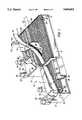
- FIG. 1is a front isometric view of a vacuum combiner partially cut away in accordance with the invention to reveal the improved wear surface design.
- FIG. 2is a top plan view of the vacuum combiner of FIG. 1 partially cut away to reveal the vacuum hole arrangement in the wear surface.
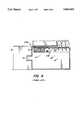
- FIG. 3is a side cross-sectional view of the vacuum conveyer combiner of FIG. 1 taken along plane (3--3) in FIG. 2 to reveal the vacuum chamber and wear surface design and construction.
- FIG. 4is a side cross-sectional view of a prior art vacuum combiner which reveals the wearstrip design and construction.
- Vacuum combiner 8in accordance with the invention is shown in FIGS: 1-3.
- Vacuum combiner 8comprises a vacuum chamber 10 having a wear surface 16 forming a side thereof.
- a plurality of conveyor belts or webs 28run longitudinally over wear surface 16 in the direction of arrow 29.
- a guide rail 18traverses wear surface 16 and conveyor belts 28 to direct articles toward a single file lane 30.
- Vacuum combiner 8is designed to minimize the knock down of articles conveyed thereon when they strike the guide rail 18 without impeding the transfer of articles between conveying surfaces 28 as they are transported towards the single file lane 30.
- Vacuum combiner 8achieves these and other advantages by replacing prior art wear strips (see FIG. 4) with wear surface 16 making combiner 8 easier and thus less expensive to assemble and requiring a smaller and thus less expensive vacuum pump.
- Prior art vacuum combiner 108included a plurality of wearstrips 109 for supporting conveyor belts 28.
- Combiner 108disadvantageously requires a larger vacuum pump than combiner 8 of the invention due to the larger vacuum suction area of the prior art device.
- the large suction area of the prior art devicealso impedes single-filing since articles tend to stay on their current belt under vacuum influence instead of freely transferring over to higher speed adjacent belts toward the single file lane.
- Vacuum chamber 10, in addition to wear surface 16,includes a bottom wall 13 and end walls 12.
- Guide 18is mounted to vacuum chamber 10 by uprights 52 and brackets 50.
- Axles 36 and sprockets 38 for training conveyor belts 28 around endless pathsare also mounted to vacuum chamber 10, with axles 36 extending through the chamber to gear boxes 32 and associated motors 34. It is understood in this regard that a single motor may be used to drive two or more belts at different speeds with appropriate gearing which may be located within or outside vacuum chamber 10.
- Wear surface 16has a vacuum suction region provided as a plurality of vacuum holes 24 which are oriented in a path indicated by line P following alongside guide rail 18 across the width of vacuum chamber 10 on the upstream side thereof. It is understood that the suction region may be provided in a manner other than a plurality of holes.
- the vacuum holes 24may be formed into the wear surface 16, in a variety of patterns. Preferably, the holes are arrayed in a plurality of staggered rows. The number of rows is selected to provide path P with a width substantially equal to a width of articles being combined. The holes are sized large enough that they will not readily clog yet small enough that several act upon each article for a given hole spacing.
- Limiting a width of path P to a width of one article, we have foundis sufficient to prevent tipping of articles when they strike guide rail 18 without impeding-transfer of articles from one conveyor web 28 to another as they are transported toward single file lane 30. Further, limiting vacuum suction to the region along path P provides a reduced vacuum intake area which allows for the use of a smaller, less expensive vacuum pump.
- Conveying belts 28are preferably formed from air previous table top conveyor, so that vacuum is pulled through the belts in the region of path P to retain articles in an upstanding position as they are guided toward lane 30.
- the speed of each individual conveyor webincreases in a direction toward single file lane 30.
- Conveyor webs 28are preferably the width of one article being transported to facilitate transfer from belt to belt, and should be provided with a smooth surface on each link to further facilitate belt to belt transfer.
- Guide rail 18non-linearly traverses the vacuum chamber 10 in a sweeping curve designed to minimize the force of contact with combining articles.
- the guide railis preferably constructed from a material sufficiently rigid to deflect articles but pliable enough to prevent undue damage.
- bin 46is a gutter-like component running along side single file lane 30 in the region where path 22 merges with lane 30.
- Airis drawn out of vacuum chamber 10 through tunnel 42 formed by tube 44 in cooperation with a vacuum pump (not depicted). As the air is drawn out of vacuum chamber 10, a vacuum is formed which causes air to flow through holes 24 of path P into vacuum chamber 10. The resulting suction prevents tipping of the articles 54 (see FIG. 3) which are being transported along path P towards single file lane 30.
- the vacuum within vacuum chamber 14is more easily maintained since there is a reduced air intake area as compared with prior art device 108 (see FIG. 4) which is completely open between wear strips 109. Accordingly, the present invention requires the utilization of a smaller, less expensive vacuum pump.
- a mass of articlesenter vacuum combiner 8 at 56, and are transported by conveyor surfaces 28 towards path P.
- the articlesmay preferably transfer to adjacent higher speed conveyors under influence of line pressure. This is possible, since vacuum suction is only applied to the articles along path P--as compared with prior art device 108 (see FIG.) wherein vacuum suction is applied over the entire conveying surface.
- Articles which do not automatically transfer to lane 30may strike guide rail 18.
- the suction generated by the vacuum holes 24 of path Pensure that articles striking guide 18 will neither tip over nor bounce back to knock over other articles.
Landscapes
- Engineering & Computer Science (AREA)
- Mechanical Engineering (AREA)
- Belt Conveyors (AREA)
Abstract
Description
The invention relates to a conveyor system for combining a mass of articles into a single file and, more particularly, to a conveyor system having multiple conveying surfaces moving at increasing speeds and a guide for moving the articles from surface to surface accelerating the articles into a single file.
In conveyor systems for articles such as cans or bottles, it is often desired to combine a mass of articles into a singe file lane. One way of accomplishing this is to provide a stationary guide above the conveying surface which is aligned at an angle with respect to the direction of travel of chains, belts or other surfaces at increasing speeds to urge the articles toward the single file lane. With this type of passive system, however, the articles often become jammed at the single file lane requiring them to be cleared and possibly damaging equipment.
Jamming is frequently caused by articles which have been knocked over or "downed" during the single file combining process. Downed articles are knocked over when they contact the stationary guide. Articles which bounce off the guide may also knock over articles which have not yet reached the guide.
One prior art attempt at solving the problem of articles knocking down when they contact the single filing guide is illustrated in FIGS. 4-5. In this prior art device, the multiple conveying surfaces are air previous and advance over a vacuum chamber. A disadvantage of this prior system is that the vacuum impedes transference of articles from one conveying surface to an adjacent conveying surface in a direction toward the single file lane, retarding maximum article throughput. A further disadvantage of this prior system is that a large and costly vacuum pump is needed to apply a sufficient vacuum on the conveying surfaces so that articles are not knocked over when they strike the guide.
The details of constructing detail of the device illustrated in FIGS. 4-5 give rise to another disadvantage which is the complexity and therefore the cost of manufacture. The conveying surfaces of this device are formed of "table top" chain having rigid links and supported from below by a pair of spaced apart wearstrips. Making, aligning, supporting and assembling the wearstrips required for a plurality of adjacent conveying surfaces can be a significant expense.
Other known prior art conveyors including those disclosed in U.S. Pat. Nos. 4,669,604; 4,768,643 and 3,352,404, include a single belt advancing over a single vacuum chamber. The conveyer combiner systems of both the 4,669,604 and the 4,768,643 patents include a deadplate (32) and (12), respectively, for accumulating cans in diagonal rows (U.S. Pat. No. 4,669,604) or in a contiguous equilateral triangle (U.S. Pat. No. 4,768,643) prior to single filing them on a vacuum belt.
U.S. Pat. No. 5,311,979 discloses a vacuum combiner system which comprises one or more conveyer belts (30-34) which may be operated at the same or different speeds and with the same or different vacuum chambers for each belt. Inwardly extending guides which may include rollers and/or downstream air jets are also disclosed.
What is desired, therefore, is an article combiner which minimizes the knockdown of articles when they strike the guide but which does not impede transfer of articles between conveying surfaces toward the single file. An article combiner which is relatively inexpensive to manufacture and easy to assemble is also desired.
Accordingly, it is an object of the present invention to provide an article combiner which is relatively simple and inexpensive to manufacture.
Another object of the invention is to provide a combiner of the above character which aids to prevent articles tipping while permitting them to freely transfer between adjacent conveying surfaces.
Still another object of the invention is to provide a combiner of the above character having a simplified wear strip design.
A further object of the above invention is to provide a combiner of the above character which will operate with a smaller vacuum pump.
These and other objects are achieved by replacement of individual wear strips with a wear surface.
The vacuum combiner disclosed herein comprises a vacuum chamber with a wear surface forming one side thereof, a plurality of air previous conveyer webs running longitudinally over the wear surface, a guide rail extending across the wear surface above the conveyor webs toward a single file lane, and a plurality of vacuum holes in the wear surface arranged along the path on an upstream side of the guide rail. The conveyer webs are driven longitudinally in the direction of the conveyer system at relative web speeds which increase in a direction approaching the single file lane.
The holes extend approximately an article width upstream of the guide to prevent article tipping without impeding article movement between the conveyer webs toward the high speed single file lane. Preferably, the holes are arrayed in a plurality of staggered lines.
The invention and its particular features will become more apparent from the following detailed description considered with reference to the accompanying drawings.
FIG. 1 is a front isometric view of a vacuum combiner partially cut away in accordance with the invention to reveal the improved wear surface design.
FIG. 2 is a top plan view of the vacuum combiner of FIG. 1 partially cut away to reveal the vacuum hole arrangement in the wear surface.
FIG. 3 is a side cross-sectional view of the vacuum conveyer combiner of FIG. 1 taken along plane (3--3) in FIG. 2 to reveal the vacuum chamber and wear surface design and construction.
FIG. 4 is a side cross-sectional view of a prior art vacuum combiner which reveals the wearstrip design and construction.
A vacuum combiner 8 in accordance with the invention is shown in FIGS: 1-3.Vacuum combiner 8 comprises avacuum chamber 10 having awear surface 16 forming a side thereof. A plurality of conveyor belts orwebs 28 run longitudinally overwear surface 16 in the direction ofarrow 29. Aguide rail 18 traverses wearsurface 16 andconveyor belts 28 to direct articles toward asingle file lane 30.Vacuum combiner 8 is designed to minimize the knock down of articles conveyed thereon when they strike theguide rail 18 without impeding the transfer of articles between conveyingsurfaces 28 as they are transported towards thesingle file lane 30.
Vacuum combiner 8 achieves these and other advantages by replacing prior art wear strips (see FIG. 4) withwear surface 16 making combiner 8 easier and thus less expensive to assemble and requiring a smaller and thus less expensive vacuum pump. Priorart vacuum combiner 108 included a plurality ofwearstrips 109 for supportingconveyor belts 28. Combiner 108 disadvantageously requires a larger vacuum pump than combiner 8 of the invention due to the larger vacuum suction area of the prior art device. The large suction area of the prior art device also impedes single-filing since articles tend to stay on their current belt under vacuum influence instead of freely transferring over to higher speed adjacent belts toward the single file lane.
Limiting a width of path P to a width of one article, we have found is sufficient to prevent tipping of articles when they strikeguide rail 18 without impeding-transfer of articles from oneconveyor web 28 to another as they are transported towardsingle file lane 30. Further, limiting vacuum suction to the region along path P provides a reduced vacuum intake area which allows for the use of a smaller, less expensive vacuum pump.
Conveyingbelts 28 are preferably formed from air previous table top conveyor, so that vacuum is pulled through the belts in the region of path P to retain articles in an upstanding position as they are guided towardlane 30. The speed of each individual conveyor web increases in a direction towardsingle file lane 30.Conveyor webs 28 are preferably the width of one article being transported to facilitate transfer from belt to belt, and should be provided with a smooth surface on each link to further facilitate belt to belt transfer.
Occasionally, articles moving along path 22 ontosingle file lane 30, may push other articles previously onlane 30 off ofcombiner 10. These articles are recovered inbin 46 which is a gutter-like component running along sidesingle file lane 30 in the region where path 22 merges withlane 30.
Air is drawn out ofvacuum chamber 10 throughtunnel 42 formed bytube 44 in cooperation with a vacuum pump (not depicted). As the air is drawn out ofvacuum chamber 10, a vacuum is formed which causes air to flow throughholes 24 of path P intovacuum chamber 10. The resulting suction prevents tipping of the articles 54 (see FIG. 3) which are being transported along path P towardssingle file lane 30. The vacuum within vacuum chamber 14 is more easily maintained since there is a reduced air intake area as compared with prior art device 108 (see FIG. 4) which is completely open between wear strips 109. Accordingly, the present invention requires the utilization of a smaller, less expensive vacuum pump.
A mass of articles (not shown)enter vacuum combiner 8 at 56, and are transported byconveyor surfaces 28 towards path P. As the articles approach path P they may preferably transfer to adjacent higher speed conveyors under influence of line pressure. This is possible, since vacuum suction is only applied to the articles along path P--as compared with prior art device 108 (see FIG.) wherein vacuum suction is applied over the entire conveying surface. Articles which do not automatically transfer tolane 30 may strikeguide rail 18. The suction generated by the vacuum holes 24 of path P ensure thatarticles striking guide 18 will neither tip over nor bounce back to knock over other articles. Once on single filepath P articles 54 are transported towards thesingle file lane 30 fromconveyor web 28 toconveyor web 28 by line pressure. Thearticles 54 are accelerated as they move betweenconveyor webs 28 towards thesingle file lane 30.
It should be understood that the foregoing is illustrative and not limiting and that obvious modifications may be made by those skilled in the art without departing from the spirit of the invention. Accordingly, reference should be made primarily to the accompanying claims, rather than the foregoing specification, to determine the scope of the invention.
Claims (19)
1. A conveyor for combining articles from a mass to a single file comprising:
a single file lane;
a vacuum chamber;
a wear surface forming at least a portion of one side of said vacuum chamber;
a plurality of conveying surfaces adjacent said single file lane, each said conveying surface supported by said wear surface and circulating at a speed increasing with proximity to said single file lane;
a guide mounted above and traversing said plurality of conveying surfaces for urging articles toward said single file lane; and
a plurality of holes in said wear surface in a path substantially parallel to said guide to aid in preventing articles from tipping upon striking said guide while permitting articles to freely move between ones of the plurality of conveying surfaces before reaching said guide.
2. The vacuum combiner of claim 1 wherein the path of said plurality of holes has a width approximately equal to a width of the article being combined.
3. The vacuum combiner of claim 2 wherein said guide is non-linear.
4. The vacuum combiner of claim 3 wherein said plurality of holes are arranged in staggered rows.
5. The vacuum combiner of claim 1 wherein the path of holes non-linearly traverses said main member.
6. The vacuum combiner of claim 1 wherein the conveying surfaces have a width approximately equal to a width of the article being combined.
7. The vacuum combiner of claim 6 wherein the single file lane has a width approximately equal to a width of the article being combined.
8. A conveyor for combining articles from a mass to a single file comprising:
a single file lane;
a vacuum chamber;
a wear surface forming at least a portion of one side of said vacuum chamber;
a plurality of air pervious conveyor belts adjacent said single file lane, each said conveying surface supported by said wear surface and circulating at a speed increasing with proximity to said single file lane;
a non-linear guide mounted above and traversing said plurality of conveying surfaces for urging articles toward said single file lane; and
a vacuum suction region in said wear surface in a path substantially parallel to said guide to aid in preventing articles from tipping upon striking said guide, a width approximately equal to a width of the article being combined.
9. The vacuum combiner of claim 8 wherein said plurality of holes are arranged in staggered rows.
10. The vacuum combiner of claim 8 wherein the path of holes non-linearly traverses said main member.
11. The vacuum combiner of claim 8 wherein the conveying surfaces have a width approximately equal to a width of the article being combined.
12. The vacuum combiner of claim 8 wherein the single file lane has a width approximately equal to a width of the article being combined.
13. A conveyor for combining articles from a mass to a single file comprising:
a single file lane;
a vacuum chamber;
a wear surface forming at least a portion of one side of said vacuum chamber;
a plurality of air pervious conveying surfaces adjacent said single file lane, each said conveying surface supported by said wear surface and circulating at a speed increasing with proximity to said single file lane;
a guide mounted above and traversing said plurality of conveying surfaces for urging articles toward said single file lane; and
a vacuum suction region in said wear surface in a path substantially parallel to said guide to aid in preventing articles from tipping upon striking said guide.
14. The vacuum combiner of claim 13 wherein the path of said plurality of holes has a width approximately equal to a width of the article being combined.
15. The vacuum combiner of claim 14 wherein said guide is non-linear.
16. The vacuum combiner of claim 15 wherein said plurality of holes are arranged in staggered rows.
17. The vacuum combiner of claim 13 wherein the path of holes non-linearly traverses said main member.
18. The vacuum combiner of claim 13 wherein the conveying surfaces have a width approximately equal to a width of the article being combined.
19. The vacuum combiner of claim 18 wherein the single file lane has a width approximately equal to a width of the article being combined.
Priority Applications (1)
| Application Number | Priority Date | Filing Date | Title |
|---|---|---|---|
| US08/535,483US5664662A (en) | 1995-09-28 | 1995-09-28 | Vacuum combiner |
Applications Claiming Priority (1)
| Application Number | Priority Date | Filing Date | Title |
|---|---|---|---|
| US08/535,483US5664662A (en) | 1995-09-28 | 1995-09-28 | Vacuum combiner |
Publications (1)
| Publication Number | Publication Date |
|---|---|
| US5664662Atrue US5664662A (en) | 1997-09-09 |
Family
ID=24134440
Family Applications (1)
| Application Number | Title | Priority Date | Filing Date |
|---|---|---|---|
| US08/535,483Expired - Fee RelatedUS5664662A (en) | 1995-09-28 | 1995-09-28 | Vacuum combiner |
Country Status (1)
| Country | Link |
|---|---|
| US (1) | US5664662A (en) |
Cited By (11)
| Publication number | Priority date | Publication date | Assignee | Title |
|---|---|---|---|---|
| US6328151B1 (en)* | 2000-02-04 | 2001-12-11 | Ambec, Inc. | Method and apparatus for feeding and forming a single row of containers along a conveyor |
| US6523674B1 (en)* | 2002-02-06 | 2003-02-25 | Ouellette Machinery Systems, Inc | Belt conveyor transition with vacuum stabilization |
| US20080302607A1 (en)* | 2006-12-02 | 2008-12-11 | Royston, Llc | Check stand with a two belted input and a slidable scanner |
| US7637917B2 (en) | 2004-10-08 | 2009-12-29 | Tyco Healthcare Group Lp | Endoscopic surgical clip applier |
| US20100252398A1 (en)* | 2009-04-02 | 2010-10-07 | Laitram, L.L.C. | Merge conveyor including high-friction rollers |
| US8900253B2 (en) | 2003-03-11 | 2014-12-02 | Covidien Lp | Clip applying apparatus with angled jaw |
| CN104495334A (en)* | 2014-12-18 | 2015-04-08 | 广州达意隆包装机械股份有限公司 | Conveyer and control method thereof |
| US20190144195A1 (en)* | 2012-11-20 | 2019-05-16 | Parata Systems, Llc | Methods and Apparatus for Dispensing Solid Articles |
| JP2020164320A (en)* | 2019-03-29 | 2020-10-08 | ユニバーサル製缶株式会社 | Can transport device |
| US11594094B2 (en) | 2020-01-22 | 2023-02-28 | Parata Systems, Llc | Methods and apparatus for dispensing solid articles |
| WO2025132212A1 (en)* | 2023-12-20 | 2025-06-26 | Khs Gmbh | Discharge device for the upright discharging of cans, container handling system having a corresponding discharge device, method for the upright discharging of cans and use of a discharge device |
Citations (7)
| Publication number | Priority date | Publication date | Assignee | Title |
|---|---|---|---|---|
| US3352404A (en)* | 1965-12-20 | 1967-11-14 | Settembrini Antoine Di | Devices for stabilizing light objects on conveyor belts |
| US4669604A (en)* | 1985-02-12 | 1987-06-02 | Precision Metal Fabricators, Inc. | Vacuum single filer |
| US4727953A (en)* | 1984-12-05 | 1988-03-01 | Honda Giken Kogyo Kabushiki Kaisha | Body frames for automatic two-wheeled vehicles |
| US4768643A (en)* | 1985-02-12 | 1988-09-06 | Meyer Conveyair, Inc. | Guide rail and deadplate alignment device for flexible wall container vacuum transfer |
| US5129504A (en)* | 1991-04-10 | 1992-07-14 | Simplimatic Engineering Company | Single file conveyor system |
| US5170879A (en)* | 1991-04-10 | 1992-12-15 | Simplimatic Engineering Company | Single file conveyor system |
| US5311979A (en)* | 1993-01-29 | 1994-05-17 | Ambec | Vacuum combiner |
- 1995
- 1995-09-28USUS08/535,483patent/US5664662A/ennot_activeExpired - Fee Related
Patent Citations (7)
| Publication number | Priority date | Publication date | Assignee | Title |
|---|---|---|---|---|
| US3352404A (en)* | 1965-12-20 | 1967-11-14 | Settembrini Antoine Di | Devices for stabilizing light objects on conveyor belts |
| US4727953A (en)* | 1984-12-05 | 1988-03-01 | Honda Giken Kogyo Kabushiki Kaisha | Body frames for automatic two-wheeled vehicles |
| US4669604A (en)* | 1985-02-12 | 1987-06-02 | Precision Metal Fabricators, Inc. | Vacuum single filer |
| US4768643A (en)* | 1985-02-12 | 1988-09-06 | Meyer Conveyair, Inc. | Guide rail and deadplate alignment device for flexible wall container vacuum transfer |
| US5129504A (en)* | 1991-04-10 | 1992-07-14 | Simplimatic Engineering Company | Single file conveyor system |
| US5170879A (en)* | 1991-04-10 | 1992-12-15 | Simplimatic Engineering Company | Single file conveyor system |
| US5311979A (en)* | 1993-01-29 | 1994-05-17 | Ambec | Vacuum combiner |
Cited By (16)
| Publication number | Priority date | Publication date | Assignee | Title |
|---|---|---|---|---|
| US6328151B1 (en)* | 2000-02-04 | 2001-12-11 | Ambec, Inc. | Method and apparatus for feeding and forming a single row of containers along a conveyor |
| US6523674B1 (en)* | 2002-02-06 | 2003-02-25 | Ouellette Machinery Systems, Inc | Belt conveyor transition with vacuum stabilization |
| US8900253B2 (en) | 2003-03-11 | 2014-12-02 | Covidien Lp | Clip applying apparatus with angled jaw |
| US9968361B2 (en) | 2003-03-11 | 2018-05-15 | Covidien Lp | Clip applying apparatus with angled jaw |
| US7637917B2 (en) | 2004-10-08 | 2009-12-29 | Tyco Healthcare Group Lp | Endoscopic surgical clip applier |
| US20080302607A1 (en)* | 2006-12-02 | 2008-12-11 | Royston, Llc | Check stand with a two belted input and a slidable scanner |
| US7967112B2 (en)* | 2006-12-02 | 2011-06-28 | Royston, LLC. | Check stand with a two belted input and a slidable scanner |
| US20100252398A1 (en)* | 2009-04-02 | 2010-10-07 | Laitram, L.L.C. | Merge conveyor including high-friction rollers |
| US7861849B2 (en)* | 2009-04-02 | 2011-01-04 | Laitram, L.L.C. | Merge conveyor including high-friction rollers |
| US10457473B2 (en)* | 2012-11-20 | 2019-10-29 | Parata Systems, Llc | Methods and apparatus for dispensing solid articles |
| US20190144195A1 (en)* | 2012-11-20 | 2019-05-16 | Parata Systems, Llc | Methods and Apparatus for Dispensing Solid Articles |
| CN104495334A (en)* | 2014-12-18 | 2015-04-08 | 广州达意隆包装机械股份有限公司 | Conveyer and control method thereof |
| JP2020164320A (en)* | 2019-03-29 | 2020-10-08 | ユニバーサル製缶株式会社 | Can transport device |
| US11594094B2 (en) | 2020-01-22 | 2023-02-28 | Parata Systems, Llc | Methods and apparatus for dispensing solid articles |
| US12293624B2 (en) | 2020-01-22 | 2025-05-06 | Parata Systems, Llc | Methods and apparatus for dispensing solid articles |
| WO2025132212A1 (en)* | 2023-12-20 | 2025-06-26 | Khs Gmbh | Discharge device for the upright discharging of cans, container handling system having a corresponding discharge device, method for the upright discharging of cans and use of a discharge device |
Similar Documents
| Publication | Publication Date | Title |
|---|---|---|
| US6182814B1 (en) | Inline vacuum slug feeder | |
| US5664662A (en) | Vacuum combiner | |
| AU706254B2 (en) | Article combiner | |
| US2168419A (en) | Conveyer | |
| DE69613727D1 (en) | Device for removing objects which are conveyed in parallel next to other objects | |
| GR3020768T3 (en) | Distributing and collecting device for products to be conveyed | |
| US4679685A (en) | Accumulating commodity conveyor | |
| GB2126555A (en) | Apparatus for spreading out and slowing down a stream of upright articles | |
| PT1081067E (en) | INSTALLATION OF BULK TRANSPORT IN PARTICULAR FOR THE TRANSPORT OF SUSPENDED PRODUCTS BY SUBPRESSION | |
| JP4394123B2 (en) | Equipment for forming product stacks | |
| US7722027B2 (en) | Vacuum belt conveyor | |
| CA2050688A1 (en) | Single file conveyor system | |
| US4311230A (en) | Article feeding mechanism | |
| CA1287319C (en) | Load spacing conveyor system | |
| EP0608103B1 (en) | Packaging machine with flight bar carton conveying system | |
| GB2044230A (en) | Apparatus for stacking flat items of bakery | |
| US4390093A (en) | Apparatus for conveying sheets such as veneer having improved wicket construction | |
| US4256214A (en) | System for overhead transport of panel members | |
| CA2308045C (en) | Level lift and drop-off arrangement for a vacuum transfer mechanism | |
| US6966423B2 (en) | Station for connecting a packaging machine, in particular blistering machine, with a feeding line, leading to a boxing machine | |
| CA1128560A (en) | Article feeding mechanism | |
| US5011132A (en) | Load accumulator having positive drive conveyor | |
| US6029800A (en) | Conveyor for articles with wave-shaped rollers | |
| EP0495261B1 (en) | A device for processing objects of different shapes and dimensions | |
| GB2255760A (en) | Conveyor assemblies. |
Legal Events
| Date | Code | Title | Description |
|---|---|---|---|
| AS | Assignment | Owner name:SIMPLIMATIC ENGINEERING COMPANY, VIRGINIA Free format text:ASSIGNMENT OF ASSIGNORS INTEREST;ASSIGNORS:WILSON, QUENTIN LYNN;WITT, MARTY NELSON;DAWSON, GEORGE HENRY III;REEL/FRAME:007855/0316 Effective date:19950926 | |
| AS | Assignment | Owner name:NATIONSBANK, N.A., MARYLAND Free format text:SECURITY INTEREST;ASSIGNOR:SIMPLIMATIC ENGINEERING COMPANY, INC.;REEL/FRAME:008621/0140 Effective date:19970514 | |
| AS | Assignment | Owner name:CENTURY SIMPLIMATIC, INC., OHIO Free format text:ASSIGNMENT OF ASSIGNORS INTEREST;ASSIGNOR:SIMPLIMATIC ENGINEERING COMPANY;REEL/FRAME:011523/0035 Effective date:20001201 | |
| REMI | Maintenance fee reminder mailed | ||
| LAPS | Lapse for failure to pay maintenance fees | ||
| FP | Lapsed due to failure to pay maintenance fee | Effective date:20010909 | |
| STCH | Information on status: patent discontinuation | Free format text:PATENT EXPIRED DUE TO NONPAYMENT OF MAINTENANCE FEES UNDER 37 CFR 1.362 |