US5663549A - System for reading a symbol by activitating a liquid crystal device to control a scanning path - Google Patents
System for reading a symbol by activitating a liquid crystal device to control a scanning pathDownload PDFInfo
- Publication number
- US5663549A US5663549AUS08/459,467US45946795AUS5663549AUS 5663549 AUS5663549 AUS 5663549AUS 45946795 AUS45946795 AUS 45946795AUS 5663549 AUS5663549 AUS 5663549A
- Authority
- US
- United States
- Prior art keywords
- bar code
- code symbol
- light beam
- light
- field
- Prior art date
- Legal status (The legal status is an assumption and is not a legal conclusion. Google has not performed a legal analysis and makes no representation as to the accuracy of the status listed.)
- Expired - Lifetime
Links
Images


Classifications
- G—PHYSICS
- G06—COMPUTING OR CALCULATING; COUNTING
- G06K—GRAPHICAL DATA READING; PRESENTATION OF DATA; RECORD CARRIERS; HANDLING RECORD CARRIERS
- G06K7/00—Methods or arrangements for sensing record carriers, e.g. for reading patterns
- G06K7/10—Methods or arrangements for sensing record carriers, e.g. for reading patterns by electromagnetic radiation, e.g. optical sensing; by corpuscular radiation
- G06K7/14—Methods or arrangements for sensing record carriers, e.g. for reading patterns by electromagnetic radiation, e.g. optical sensing; by corpuscular radiation using light without selection of wavelength, e.g. sensing reflected white light
- G06K7/1404—Methods for optical code recognition
- G06K7/146—Methods for optical code recognition the method including quality enhancement steps
- G06K7/1473—Methods for optical code recognition the method including quality enhancement steps error correction
- G—PHYSICS
- G06—COMPUTING OR CALCULATING; COUNTING
- G06K—GRAPHICAL DATA READING; PRESENTATION OF DATA; RECORD CARRIERS; HANDLING RECORD CARRIERS
- G06K7/00—Methods or arrangements for sensing record carriers, e.g. for reading patterns
- G06K7/10—Methods or arrangements for sensing record carriers, e.g. for reading patterns by electromagnetic radiation, e.g. optical sensing; by corpuscular radiation
- G06K7/10544—Methods or arrangements for sensing record carriers, e.g. for reading patterns by electromagnetic radiation, e.g. optical sensing; by corpuscular radiation by scanning of the records by radiation in the optical part of the electromagnetic spectrum
- G06K7/10554—Moving beam scanning
- G06K7/10564—Light sources
- G06K7/10574—Multiple sources
- G—PHYSICS
- G06—COMPUTING OR CALCULATING; COUNTING
- G06K—GRAPHICAL DATA READING; PRESENTATION OF DATA; RECORD CARRIERS; HANDLING RECORD CARRIERS
- G06K7/00—Methods or arrangements for sensing record carriers, e.g. for reading patterns
- G06K7/10—Methods or arrangements for sensing record carriers, e.g. for reading patterns by electromagnetic radiation, e.g. optical sensing; by corpuscular radiation
- G06K7/10544—Methods or arrangements for sensing record carriers, e.g. for reading patterns by electromagnetic radiation, e.g. optical sensing; by corpuscular radiation by scanning of the records by radiation in the optical part of the electromagnetic spectrum
- G06K7/10554—Moving beam scanning
- G06K7/10594—Beam path
- G06K7/10603—Basic scanning using moving elements
- G06K7/10673—Parallel lines
- G—PHYSICS
- G06—COMPUTING OR CALCULATING; COUNTING
- G06K—GRAPHICAL DATA READING; PRESENTATION OF DATA; RECORD CARRIERS; HANDLING RECORD CARRIERS
- G06K7/00—Methods or arrangements for sensing record carriers, e.g. for reading patterns
- G06K7/10—Methods or arrangements for sensing record carriers, e.g. for reading patterns by electromagnetic radiation, e.g. optical sensing; by corpuscular radiation
- G06K7/10544—Methods or arrangements for sensing record carriers, e.g. for reading patterns by electromagnetic radiation, e.g. optical sensing; by corpuscular radiation by scanning of the records by radiation in the optical part of the electromagnetic spectrum
- G06K7/10554—Moving beam scanning
- G06K7/10594—Beam path
- G06K7/10683—Arrangement of fixed elements
- G06K7/10702—Particularities of propagating elements, e.g. lenses, mirrors
- G—PHYSICS
- G06—COMPUTING OR CALCULATING; COUNTING
- G06K—GRAPHICAL DATA READING; PRESENTATION OF DATA; RECORD CARRIERS; HANDLING RECORD CARRIERS
- G06K7/00—Methods or arrangements for sensing record carriers, e.g. for reading patterns
- G06K7/10—Methods or arrangements for sensing record carriers, e.g. for reading patterns by electromagnetic radiation, e.g. optical sensing; by corpuscular radiation
- G06K7/14—Methods or arrangements for sensing record carriers, e.g. for reading patterns by electromagnetic radiation, e.g. optical sensing; by corpuscular radiation using light without selection of wavelength, e.g. sensing reflected white light
- G06K7/1404—Methods for optical code recognition
- G06K7/1408—Methods for optical code recognition the method being specifically adapted for the type of code
- G06K7/1417—2D bar codes
Definitions
- This inventionrelates to bar code reader devices, and more particularly to apparatus for generating a scanned light beam for use in reading bar code symbols.
- Bar code readersare disclosed in U.S. Pat. Nos. 4,387,297, 4,409,470, 4,251,798, and 4,760,248, all assigned to Symbol Technologies, Inc.
- One of the elements of the prior bar code scanners most susceptible to improvement along these linesis the mechanical scanner device.
- the scanner devicesmay consist of a mirror mounted on a stepper motor; the mirror includes a flat portion to direct the outgoing laser beam and also a concave portion to collect reflected light and focus it upon a photodetector.
- Bar code readersemploy decoding circuitry to interpret the signals produced by a photodetector receiving the reflected light from the bar code symbol.
- Conventional decoding schemesrely upon data collected by a single scanning spot moved linearly across the field where the bar code symbol is located. The bar code data is embedded in background noise, and the decoding circuitry is more effective if the signal can be enhanced. To this end, faster scanning rates would permit the implementation of multiple scans to increase reliability of the data collected, but the mechanical scan generators previously used constrict the speed and thus place limitations on the multiple scan approach.
- a bar code scanner and methodincluding structure and steps generating a scanning light beam, detecting the light beam, changing the light beam in accordance with said detected light beam, directing the light beam upon a field where the bar code symbol may be present, varying a light path of the scanning beam by changing an electrical signal applied to a liquid crystal device in the path to thereby create a scan line to traverse the field as the electrical signal changes, detecting light reflected by the field, and decoding the detected reflected light while ignoring segments of the reflected light corresponding to areas indicated as defective based on the detected scanning light beam.
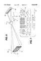
- FIG. 1is a diagram in schematic form of a bar code scanner employing a linear array of cells of a liquid crystal device of a single light source and mechanical scanning, according to one embodiment of the invention
- FIG. 2is an electrical diagram in schematic form of a part of the system of FIG. 1;
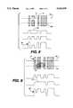
- FIG. 3a-3dare timing diagrams showing events vs. time for various events or voltages in the device of FIGS. 1 and 2;
- FIG. 4is an enlarged view of a part of the linear array of light sources of FIG. 1, according to another embodiment
- FIG. 5is a pictorial view, partly broken away, of the device of FIGS. 1-4 mounted in a hand-held portable bar code reader unit;
- FIG. 6is a diagram in schematic form of a bar code scanner employing dual arrays of light sources instead of a single array as in FIG. 1, according to another embodiment of the invention
- FIG. 7is a timing diagram showing events or voltage vs. time for certain occurrences in the system of FIG. 7 illustrating the cancellation of background noise;
- FIGS. 8 and 9are timing diagrams showing events or voltage vs. time for certain occurrences in the system of FIG. 6 illustrating compensation for faults in the bar code
- FIG. 9is a timing diagram showing events or voltage vs. time for certain occurrences in the system of FIG. 6.
- a bar code scanneremploys a linear array 10 of cells of a liquid crystal device 11 that are activated one at a time in sequence.
- FIG. 1includes a laser crystal device 10, a device for applying an electrical signal to the LCD or drive circuit 21 and a light source 105.
- the light output from the array 10is focused by a suitable lens system 12 onto a line 13 at the focal plane of the lens system, i.e., the image of the array 10 will appear as a line 13 scanning across the focal plane.
- a targetsuch as a bar code symbol 14 is scanned by the line 13, where the light beam scanning the line 13 functions just as the laser scan used in more conventional bar code readers.
- the spot size shown for the scan line 13is merely illustrative; the actual spot size representing the images of the cells 11 may be the same size or larger than the minimum dimensions of the bars and spaces.
- a microprocessor device 20is used to drive the array 10 by way of a multiplexed drive circuit 21, and also used to decode the detected and shaped bar code signal on the line 19.
- the drive circuit 21may consist of a number of transistors 22 as seen in FIG.
- the base-emitter circuits of the transistors 22are driven from a decoder 23 that receives a one-of-N address signal on lines 24 from the microprocessor 20 to activate a particular one of the cells 11; in this manner, the cells 11 can be turned on one at a time in a rapid sequence, starting at one end of the array and proceeding to the other.
- the pulse width used to drive the base of a transistor 22 to turn on a cell 11may be variable by feedback based on reflected light, as described below.
- a monitoring photodiode 25is positioned in the reader housing to detect the overall light output from the cells 11, using a suitable optic arrangement, if necessary.
- the electrical output from this photodiode 25is applied by a line 26 and a wave shaper or digitizer 18a to an input of the microprocessor 20.
- This monitoring photodiode 25performs several tasks. First, the output power of the cells 11 can be maintained in the proper range by adjustment of the pulse width of the driving current pulses, e.g., by an address strobe applied to the decoder 23 from the microprocessor 20 via a line 27. Feedback to adjust the pulse width used to drive the transistors 22 is thus provided. Or, the drive current for the cells 11 could be adjusted by varying the level of the power supply to the cells 11.
- the monitoring photodiode 25supplies an input to the microprocessor 20 for use in fault detection and correction; if one or more of the laser cells 11 is faulty and does not allow light to pass then the position or spot in the scan line 13 where this laser cell was supposed to have illuminated is always dark and so is interpreted as a black bar in the return signal even though the bar code symbol 14 actually may have a white space in this position.
- the microprocessor 20is programmed to ignore or "blank" any signal on the input line 17 during the time slot of the faulty cell or cells. Referring to FIG.
- the electrical output of the monitoring photodiode 25 on line 26should be a continuous series of overlapping or juxtaposed pulses 30, but where there is a faulty diode there will be a space 31, and so the microprocessor generates a blanking period 32 as seen in FIG. 3b.
- a bar code symbol 14 as seen in FIG. 3cshould return a signal 33 on line 17 as seen in FIG. 3d, but the return during the blanking period 32 is false, so this input is ignored or considered to be either black or white; if the code can be decoded with this ambiguity, then a valid reading is possible, if not, then a false reading is at least avoided and another shot by the user, or an automatic rescan without user intervention, may produce a valid reading. In any event, a fault can be signalled so the user can return the reader unit for repair.
- the optical system used to focus the array 10 upon the focal plane of the bar code symbol 14may employ a large number of individual lenslets 12a, 12b, etc., one for each cell 11, for collimating the light from each diode.
- Each of the lenslets 12a, 12b, etc.is individually positioned to collimate the light for one cell, then a lens 12 is used to focus a single spot for each diode onto the focal plane where the bar code symbol 14 is expected to be, to thereby create the line 13 of spots as before.
- the bar code scanner of FIGS. 1-4may be mounted in a portable hand-held unit 35 having a handle 36 gripped by the user.
- the laser scan beam 37 generated by the linear array 10exits through a window in the front of the unit, and the reflected light from the bar code symbol 14 also enters by this window to reach the photodetector 15.
- the microprocessor 20 and other circuitry of FIGS. 1 and 2are mounted on a circuit board within the unit 35, as well as a battery if the unit is self-powered.
- the unit 35is coupled to a central station by an RF link or by a wire cable.
- a finger-activated trigger switch 39is employed to activate the scan, detect and decode functions when the user points the unit 35 toward a symbol 14.
- the scan patterncan be flexibly adapted; for example, if the bar code is recognized to occupy only a fraction of the full scan line 13, power can be conserved by applying drive current only to the transistors 22 for cells 11 that actually illuminate the bar code symbol 14 itself. Similarly, more scans can be applied to a small portion of the bar code symbol by limiting the addressing applied to the multiplex drive circuit 15 if decoding of the signal on line 17 indicates an ambiguity for this portion.
- FIG. 6another embodiment of the invention is illustrated wherein two of the linear arrays 10 and 10b are employed instead of only one as was the case in the embodiment of FIG. 1.
- the construction of the remaining parts of the systemare the same as in FIG. 1.
- Use of two arrays 10a and 10bprovides two scan lines 13a and 13b, one above the other, separated from one another by a distance corresponding to the physical separation of the arrays 10a and 10b and the magnification in the optical system 12.
- This dual scan line techniquemay be advantageously employed in several ways.
- the two scan lines 13a and 13bare likewise in sync; in this case if the two scan lines traverse the same bar code symbol 14, the reflected light received by the photodetector 15 is also in sync from the two scans 13a and 13b.
- the advantage of having two scan linesmay be understood by reference to FIG. 7, where the background areas 53 are seen to return uncorrelated signals 54, whereas the bar code symbol returns correlated waveforms from the two parts of the symbol 14 being scanned by the two scan lines 13a and 13b.
- the single detector 15collects reflected light from the two scans at the same time and sums the intensities of the reflections, so the contrast of the overall signal 55 detected from the bar code 14 is enhanced.
- the areas 53 outside the bar code symbol 14will result in different signals, and so the overall contrast from these areas is reduced.
- the digitizing circuitry used to shape the analog waveform on the line 17 and recover the bar code informationcan more readily distinguish the transitions in the bar code region of the signal from the uncorrelated returns from the areas 53. Referring to FIGS. 8 and 9, another advantage to the dual scans of FIG. 7 is that bar code imperfections can be compensated for. If the bar code symbol 14 has a defect in the form of a gap 57 as seen in FIG.
- the signal returned by the scan line 13bwould have a corresponding false area 58 whereas the return from the scan line 13a would be valid.
- the composite signal 59 on the line 17 at the output of the photodiode 15would still be able to be interpreted to recover valid data.
- the defectis in the form of a black spot 60
- the light return for one scan linewill have a false area 61 appearing as if there was a very wide bar in the symbol, but the composite electrical signal 62 representing the sum of both scans 13a and 13b has distinct transitions and can be decoded to produce valid bar code data.
- the scan generationmay use oscillating mirrors
- the embodiments of bar code scanner devices as with no moving parts as described abovehave several advantages for some purposes, when compared to scanners that use electromechanical components.
- the scan ratecan be much faster, so the amount of time the laser is on can be reduced, lowering power drain.
- the faster speedwill also allow a large number of scans to be accomplished for one "read" operation, then the data signals correlated with one another using a suitable algorithm to increase the precision of the decode.
- the scan patterncan be flexibly adapted, i.e., the scan can be tailored to fit the particular bar code symbol and position; e.g., after an initial scan it is determined that the location and width of the bar code symbol in the field of view is at a specific place, and so the field is re-scanned at only this location, which will use less power.
- improvements in reliabilitycan be provided in a device with no moving parts but instead implemented with only electronic components and fixed optical devices.
- the bar code scanner methods disclosed above wherein multiple scan lines are employedprovide other features of importance.
- the reliability of the decoding processcan be enhanced by producing a composite signal from multiple simultaneous scans, where the effects of noise or defects can be minimized.
- the increased scanning speed permitted by the use of no moving partsallows the multiple scans to be sequential, one line at a time, which allows the reflected light from the multiple scan lines to be separated when using only one photodetector; this arrangement permits scanning of multiple-row bar code symbols or the like.
Landscapes
- Physics & Mathematics (AREA)
- Engineering & Computer Science (AREA)
- Electromagnetism (AREA)
- Health & Medical Sciences (AREA)
- General Health & Medical Sciences (AREA)
- Toxicology (AREA)
- Artificial Intelligence (AREA)
- Computer Vision & Pattern Recognition (AREA)
- General Physics & Mathematics (AREA)
- Theoretical Computer Science (AREA)
- Quality & Reliability (AREA)
- Mechanical Optical Scanning Systems (AREA)
Abstract
Description
This application is a divisional of U.S. patent application Ser. No. 08/098,991, filed Jul. 29, 1993 now U.S. Pat. No. 5,545,886 which is a divisional of U.S. patent application Ser. No. 07/864,367 filed Apr. 6, 1992, now U.S. Pat. No. 5,258,605, which is a continuation of U.S. patent application Ser. No. 07/493,134 filed Mar. 13, 1990, now abandoned. The U.S. patent applications are hereby incorporated by reference.
This invention relates to bar code reader devices, and more particularly to apparatus for generating a scanned light beam for use in reading bar code symbols.
Bar code readers are disclosed in U.S. Pat. Nos. 4,387,297, 4,409,470, 4,251,798, and 4,760,248, all assigned to Symbol Technologies, Inc. The bar code readers described in these patents, as well as other devices of this type that are commercially available, usually employ oscillating mirrors or similar mechanical means to generate a scanning pattern. While such devices are widely used in retail and other business establishments today and have been quite successful in accomplishing their objectives, there is nevertheless a continuing requirement to improve reliability, reduce power consumption, reduce size and weight, lower the parts cost and manufacturing cost, and increase the speed and accuracy of operation. One of the elements of the prior bar code scanners most susceptible to improvement along these lines is the mechanical scanner device. The scanner devices may consist of a mirror mounted on a stepper motor; the mirror includes a flat portion to direct the outgoing laser beam and also a concave portion to collect reflected light and focus it upon a photodetector.
Bar code readers employ decoding circuitry to interpret the signals produced by a photodetector receiving the reflected light from the bar code symbol. Conventional decoding schemes rely upon data collected by a single scanning spot moved linearly across the field where the bar code symbol is located. The bar code data is embedded in background noise, and the decoding circuitry is more effective if the signal can be enhanced. To this end, faster scanning rates would permit the implementation of multiple scans to increase reliability of the data collected, but the mechanical scan generators previously used constrict the speed and thus place limitations on the multiple scan approach.
It is the principal object of the invention to provide a bar code reader or the like that does not require mechanical devices such as oscillating mirrors to cause a light beam to scan a symbol to be read. Another object is to provide a bar code reader that is capable of faster scan, as by implementing the scan with no moving parts. A further object is to take advantage of fast scanning techniques to provide multiple scans to thereby increase the signal recovery ability, i.e., increase the likelihood of recovering a valid decode of the bar code signal. In addition, the capability of providing multiple scans using a fast scan method permits improved facility for reading two dimensional bar code symbols of the type having multiple rows of bar code patterns. Other objects include reducing the size, weight and power consumption of a laser scan type of bar code reader, as well as reducing the manufacturing cost and increasing the reliability and operating lifetime of such devices.
In accordance with one embodiment of the invention, a bar code scanner and method are provided including structure and steps generating a scanning light beam, detecting the light beam, changing the light beam in accordance with said detected light beam, directing the light beam upon a field where the bar code symbol may be present, varying a light path of the scanning beam by changing an electrical signal applied to a liquid crystal device in the path to thereby create a scan line to traverse the field as the electrical signal changes, detecting light reflected by the field, and decoding the detected reflected light while ignoring segments of the reflected light corresponding to areas indicated as defective based on the detected scanning light beam.
The novel features characteristic of the invention are set forth in the appended claims. The invention itself, however, as well as other features and advantages thereof, will be best understood by reference to a detailed description of specific embodiments, when read in conjunction with the accompanying drawings, wherein:
FIG. 1 is a diagram in schematic form of a bar code scanner employing a linear array of cells of a liquid crystal device of a single light source and mechanical scanning, according to one embodiment of the invention;
FIG. 2 is an electrical diagram in schematic form of a part of the system of FIG. 1;
FIG. 3a-3d are timing diagrams showing events vs. time for various events or voltages in the device of FIGS. 1 and 2;
FIG. 4 is an enlarged view of a part of the linear array of light sources of FIG. 1, according to another embodiment;
FIG. 5 is a pictorial view, partly broken away, of the device of FIGS. 1-4 mounted in a hand-held portable bar code reader unit;
FIG. 6 is a diagram in schematic form of a bar code scanner employing dual arrays of light sources instead of a single array as in FIG. 1, according to another embodiment of the invention;
FIG. 7 is a timing diagram showing events or voltage vs. time for certain occurrences in the system of FIG. 7 illustrating the cancellation of background noise;
FIGS. 8 and 9 are timing diagrams showing events or voltage vs. time for certain occurrences in the system of FIG. 6 illustrating compensation for faults in the bar code; and
FIG. 9 is a timing diagram showing events or voltage vs. time for certain occurrences in the system of FIG. 6.
Referring to FIG. 1, a bar code scanner according to one embodiment of the invention employs alinear array 10 of cells of aliquid crystal device 11 that are activated one at a time in sequence. FIG. 1 includes alaser crystal device 10, a device for applying an electrical signal to the LCD ordrive circuit 21 and alight source 105. The light output from thearray 10 is focused by asuitable lens system 12 onto aline 13 at the focal plane of the lens system, i.e., the image of thearray 10 will appear as aline 13 scanning across the focal plane. A target such as abar code symbol 14 is scanned by theline 13, where the light beam scanning theline 13 functions just as the laser scan used in more conventional bar code readers. The advantage of the scanning arrangement of FIG. 1, however, is that there are no moving parts, and also the scan rate can be much faster than if limited by mechanical oscillating mirrors or the like. The spot size shown for thescan line 13 is merely illustrative; the actual spot size representing the images of thecells 11 may be the same size or larger than the minimum dimensions of the bars and spaces.
Light reflected from thebar code symbol 14 is focused upon aphotodetector diode 15 through alens system 16, producing an analog electrical output serially on aline 17, and this serial output is shaped via wave-shaping circuitry 18 to produce a square-wave type of signal on aline 19 to be then decoded in the usual manner to identify the bar code symbol. Amicroprocessor device 20 is used to drive thearray 10 by way of a multiplexeddrive circuit 21, and also used to decode the detected and shaped bar code signal on theline 19. Thedrive circuit 21 may consist of a number oftransistors 22 as seen in FIG. 2, each being connected in series with one of thecells 11 of thearray 10; the base-emitter circuits of thetransistors 22 are driven from adecoder 23 that receives a one-of-N address signal onlines 24 from themicroprocessor 20 to activate a particular one of thecells 11; in this manner, thecells 11 can be turned on one at a time in a rapid sequence, starting at one end of the array and proceeding to the other. The pulse width used to drive the base of atransistor 22 to turn on acell 11 may be variable by feedback based on reflected light, as described below.
Amonitoring photodiode 25 is positioned in the reader housing to detect the overall light output from thecells 11, using a suitable optic arrangement, if necessary. The electrical output from thisphotodiode 25 is applied by aline 26 and a wave shaper or digitizer 18a to an input of themicroprocessor 20. Thismonitoring photodiode 25 performs several tasks. First, the output power of thecells 11 can be maintained in the proper range by adjustment of the pulse width of the driving current pulses, e.g., by an address strobe applied to thedecoder 23 from themicroprocessor 20 via aline 27. Feedback to adjust the pulse width used to drive thetransistors 22 is thus provided. Or, the drive current for thecells 11 could be adjusted by varying the level of the power supply to thecells 11. Second, themonitoring photodiode 25 supplies an input to themicroprocessor 20 for use in fault detection and correction; if one or more of thelaser cells 11 is faulty and does not allow light to pass then the position or spot in thescan line 13 where this laser cell was supposed to have illuminated is always dark and so is interpreted as a black bar in the return signal even though thebar code symbol 14 actually may have a white space in this position. To prevent this incorrect interpretation, themicroprocessor 20 is programmed to ignore or "blank" any signal on theinput line 17 during the time slot of the faulty cell or cells. Referring to FIG. 3a, the electrical output of themonitoring photodiode 25 online 26 should be a continuous series of overlapping or juxtaposedpulses 30, but where there is a faulty diode there will be aspace 31, and so the microprocessor generates ablanking period 32 as seen in FIG. 3b. Abar code symbol 14 as seen in FIG. 3c should return a signal 33 online 17 as seen in FIG. 3d, but the return during theblanking period 32 is false, so this input is ignored or considered to be either black or white; if the code can be decoded with this ambiguity, then a valid reading is possible, if not, then a false reading is at least avoided and another shot by the user, or an automatic rescan without user intervention, may produce a valid reading. In any event, a fault can be signalled so the user can return the reader unit for repair.
As seen in FIG. 4, the optical system used to focus thearray 10 upon the focal plane of thebar code symbol 14 may employ a large number ofindividual lenslets cell 11, for collimating the light from each diode. Each of thelenslets lens 12 is used to focus a single spot for each diode onto the focal plane where thebar code symbol 14 is expected to be, to thereby create theline 13 of spots as before.
Referring now to FIG. 5, the bar code scanner of FIGS. 1-4 may be mounted in a portable hand-heldunit 35 having ahandle 36 gripped by the user. Thelaser scan beam 37 generated by thelinear array 10 exits through a window in the front of the unit, and the reflected light from thebar code symbol 14 also enters by this window to reach thephotodetector 15. Themicroprocessor 20 and other circuitry of FIGS. 1 and 2 are mounted on a circuit board within theunit 35, as well as a battery if the unit is self-powered. Theunit 35 is coupled to a central station by an RF link or by a wire cable. A finger-activatedtrigger switch 39 is employed to activate the scan, detect and decode functions when the user points theunit 35 toward asymbol 14.
Using the scanner device of FIGS. 1-5 with no moving parts, the scan pattern can be flexibly adapted; for example, if the bar code is recognized to occupy only a fraction of thefull scan line 13, power can be conserved by applying drive current only to thetransistors 22 forcells 11 that actually illuminate thebar code symbol 14 itself. Similarly, more scans can be applied to a small portion of the bar code symbol by limiting the addressing applied to themultiplex drive circuit 15 if decoding of the signal online 17 indicates an ambiguity for this portion.
Referring to FIG. 6, another embodiment of the invention is illustrated wherein two of thelinear arrays arrays scan lines arrays optical system 12. This dual scan line technique may be advantageously employed in several ways. First, if the two rows ofcells 11 in the twoarrays scan lines bar code symbol 14, the reflected light received by thephotodetector 15 is also in sync from the twoscans background areas 53 are seen to returnuncorrelated signals 54, whereas the bar code symbol returns correlated waveforms from the two parts of thesymbol 14 being scanned by the twoscan lines single detector 15 collects reflected light from the two scans at the same time and sums the intensities of the reflections, so the contrast of theoverall signal 55 detected from thebar code 14 is enhanced. On the other hand, theareas 53 outside thebar code symbol 14 will result in different signals, and so the overall contrast from these areas is reduced. The digitizing circuitry used to shape the analog waveform on theline 17 and recover the bar code information can more readily distinguish the transitions in the bar code region of the signal from the uncorrelated returns from theareas 53. Referring to FIGS. 8 and 9, another advantage to the dual scans of FIG. 7 is that bar code imperfections can be compensated for. If thebar code symbol 14 has a defect in the form of agap 57 as seen in FIG. 8, then the signal returned by thescan line 13b would have a correspondingfalse area 58 whereas the return from thescan line 13a would be valid. Thecomposite signal 59 on theline 17 at the output of thephotodiode 15 would still be able to be interpreted to recover valid data. Similarly, as illustrated in FIG. 9, if the defect is in the form of ablack spot 60, the light return for one scan line will have afalse area 61 appearing as if there was a very wide bar in the symbol, but the compositeelectrical signal 62 representing the sum of bothscans
When twoscan lines symbol 14. The permissible misalignment depends upon the bar code density and the amount of physical separation between the twoscan lines
Although according to various features of the invention the scan generation may use oscillating mirrors, the embodiments of bar code scanner devices as with no moving parts as described above have several advantages for some purposes, when compared to scanners that use electromechanical components. First, the scan rate can be much faster, so the amount of time the laser is on can be reduced, lowering power drain. The faster speed will also allow a large number of scans to be accomplished for one "read" operation, then the data signals correlated with one another using a suitable algorithm to increase the precision of the decode. Second, the scan pattern can be flexibly adapted, i.e., the scan can be tailored to fit the particular bar code symbol and position; e.g., after an initial scan it is determined that the location and width of the bar code symbol in the field of view is at a specific place, and so the field is re-scanned at only this location, which will use less power. Third, after an initial scan there can be a re-scan of only a small part that showed an ambiguous decode, attempting to get a valid decode of only the troublesome part. Fourth, improvements in reliability can be provided in a device with no moving parts but instead implemented with only electronic components and fixed optical devices.
In another aspect, the bar code scanner methods disclosed above wherein multiple scan lines are employed provide other features of importance. The reliability of the decoding process can be enhanced by producing a composite signal from multiple simultaneous scans, where the effects of noise or defects can be minimized. Or, the increased scanning speed permitted by the use of no moving parts allows the multiple scans to be sequential, one line at a time, which allows the reflected light from the multiple scan lines to be separated when using only one photodetector; this arrangement permits scanning of multiple-row bar code symbols or the like.
While this invention has been described with reference to specific embodiments, this description is not meant to be construed in a limiting sense. Various modifications of the disclosed embodiments, as well as other embodiments of the invention and variations in the character of the disclosed or other embodiments, will be apparent to persons skilled in the art upon reference to this description. It is therefore contemplated that the appended claims will cover any such modifications or embodiments, or variations therein, as fall within the true scope of the invention.
Claims (22)
1. A method of reading a bar code symbol comprising the steps of:
generating a scanning light beam;
detecting said light beam;
changing the light beam in accordance with said detected light beam;
directing said light beam upon a field where said bar code symbol may be present;
varying a light path of said scanning beam by changing an electrical signal applied to a liquid crystal device in said path to thereby create a scan line to traverse said field as the electrical signal changes;
detecting light reflected by said field; and
decoding said detected reflected light while ignoring segments of the reflected light corresponding to areas indicated as defective based on the detected scanning light beam.
2. A method of reading a bar code symbol according to claim 1 further including steps for:
detecting the light reflected from the field; and
decoding the bar code symbol in response to the detected light.
3. A method of reading a bar code symbol according to claim 1 further including steps for:
determining whether the scanning light beam is at a predetermined power level in response to the detected light beam;
detecting the light reflected from the field;
determining, when the scanning light is not at a predetermined power level, whether the bar code symbol can be successfully decoded based upon the detected reflected light; and
rescanning the bar code symbol when it is determined that the bar code symbol can not be successfully decoded.
4. A method of reading a bar code symbol according to claim 1 further including steps for:
determining whether the scanning light beam is at a predetermined power level in response to the detected light beam;
detecting the light reflected from the field;
determining, when the scanning light is not at a predetermined power level, whether the bar code symbol can be successfully decoded based upon the detected reflected light; and
signaling an error to a user when it is determined that the bar code symbol can not be successfully decoded.
5. A method of reading a bar code symbol according to claim 1 further including the steps of:
recognizing that a bar code symbol occupies a fraction of said field; and
directing the scanning light beam at the fraction of the field containing the bar code symbol.
6. A method of reading a bar code symbol comprising the steps of:
generating a light beam scan line by sequentially activating an array of cells in a liquid crystal device;
detecting the generated light beam scan line;
changing an electrical signal applied to the liquid crystal device in accordance with the detected light beam scan line to thereby adjust the light beam;
directing the light beam scan line to a field where said bar code symbol may be present;
detecting light reflected from said field to produce an electrical signal corresponding to said scan line; and
decoding said electrical signal while ignoring segments of the reflected light corresponding to areas indicated as defective based on the detected generated light beam.
7. A method according to claim 6 further including the steps of:
generating a plurality of light beam scan lines; and
varying the number of said plurality of light beam scan lines by varying the magnitude or frequency of a voltage applied to said liquid crystal device.
8. A method of reading a bar code symbol according to claim 6, further including a step of decoding the bar code symbol in response to the detected reflected light.
9. A method of reading a bar code symbol according to claim 6 wherein the step of generating a light beam scan line includes the step of
activating the liquid crystal device in a sequence starting at one end of the array to the other end of the array.
10. A method of reading a bar code symbol according to claim 6 further including the steps of:
recognizing that a bar code symbol occupies a fraction of said field; and
directing the light beam scan line at the fraction of the field containing the bar code symbol.
11. A bar code symbol reader comprising:
a light source for generating a scanning light beam;
a first photodetector for detecting the generated scanning light beam;
means for adjusting the light beam in accordance with the detected light beam;
a lens for directing the light beam upon a field where said bar code symbol may be present;
means for varying a light path of said scanning beam by changing an electrical signal applied to a liquid crystal device in said path to thereby create a scan line to traverse said field as the electrical signal changes;
means for detecting light reflected by said field; and
means for decoding said detected reflected light while ignoring segments of the reflected light corresponding to areas indicated as defective based on the detected scanning light beam.
12. A bar code symbol reader according to claim 11 further including:
a second photodetector for detecting the light reflected from the field; and
means for decoding the bar code symbol in response to the detected reflected light.
13. A bar code reader according to claim 11 further including:
means for determining whether the scanning light beam is at a predetermined power level in response to the detected light beam;
a second photodetector for detecting the light reflected from the field;
means for determining, when the scanning light is not at a predetermined power level, whether the bar code symbol can be successfully decoded based upon the detected reflected light; and
means for rescanning the bar code symbol when it is determined that the bar code symbol can not be successfully decoded.
14. A bar code symbol reader according to claim 11 further including:
means for determining whether the scanning light beam is at a predetermined power level in response to the detected light beam;
a second photodetector for detecting the light reflected from the field;
means for determining, when the scanning light is not at a predetermined power level, whether the bar code symbol can be successfully decoded based upon the detected reflected light; and
means for signalling an error to a user when it is determined that the bar code symbol can not be successfully decoded.
15. A bar code symbol reader according to claim 11 wherein the means for varying the light path includes a microprocessor.
16. A bar code symbol reader according to claim 11 further including:
means for recognizing that a bar code symbol occupies a fraction of said field; and
means for directing the scanning light beam at the fraction of the field containing the bar code symbol.
17. A bar code symbol reader comprising:
a light source for generating a light beam;
an electrical source for generating a scan line by sequentially activating a plurality of cells in a liquid crystal device;
a first photodetector for detecting the generated scan line;
means for changing an electrical signal applied to the liquid crystal device based upon the detected scan line;
a lens for directing the light beam scan line to a field where said bar code symbol may be present;
a second photodetector for detecting light reflected from said field to produce an electrical signal corresponding to said scan line; and
means for decoding said detected reflected light ignoring segments of the reflected light corresponding to areas indicated as defective based on the detected generated scan line.
18. The bar code symbol reader of claim 17 wherein the liquid crystal device outputs a plurality of scan lines.
19. The bar code symbol reader of claim 18 wherein the magnitude and frequency of the electrical signal controls the number of scan lines output by the liquid crystal device.
20. The bar code reader according to claim 18 further including means for varying the number of the plurality of light beam scan lines by varying a voltage applied to the liquid crystal device.
21. A bar code symbol reader according to claim 17 further including means for decoding the bar code symbol in response to the electrical signal.
22. A bar code symbol reader according to claim 17 further including:
means for recognizing that a bar code symbol occupies a fraction of said field; and
means for directing the generated light beam at the fraction of the field containing the bar code symbol.
Priority Applications (1)
| Application Number | Priority Date | Filing Date | Title |
|---|---|---|---|
| US08/459,467US5663549A (en) | 1990-03-13 | 1995-06-02 | System for reading a symbol by activitating a liquid crystal device to control a scanning path |
Applications Claiming Priority (4)
| Application Number | Priority Date | Filing Date | Title |
|---|---|---|---|
| US49313490A | 1990-03-13 | 1990-03-13 | |
| US07/864,367US5258605A (en) | 1990-03-13 | 1992-04-06 | Scan generators for bar code reader using linear array of lasers |
| US08/098,991US5545886A (en) | 1990-03-13 | 1993-07-29 | Barcode scanner using an array of light emitting elements which are selectively activated |
| US08/459,467US5663549A (en) | 1990-03-13 | 1995-06-02 | System for reading a symbol by activitating a liquid crystal device to control a scanning path |
Related Parent Applications (1)
| Application Number | Title | Priority Date | Filing Date |
|---|---|---|---|
| US08/098,991DivisionUS5545886A (en) | 1990-03-13 | 1993-07-29 | Barcode scanner using an array of light emitting elements which are selectively activated |
Publications (1)
| Publication Number | Publication Date |
|---|---|
| US5663549Atrue US5663549A (en) | 1997-09-02 |
Family
ID=27050978
Family Applications (5)
| Application Number | Title | Priority Date | Filing Date |
|---|---|---|---|
| US07/864,367Expired - LifetimeUS5258605A (en) | 1990-03-13 | 1992-04-06 | Scan generators for bar code reader using linear array of lasers |
| US08/098,991Expired - LifetimeUS5545886A (en) | 1990-03-13 | 1993-07-29 | Barcode scanner using an array of light emitting elements which are selectively activated |
| US08/459,467Expired - LifetimeUS5663549A (en) | 1990-03-13 | 1995-06-02 | System for reading a symbol by activitating a liquid crystal device to control a scanning path |
| US08/458,880Expired - Fee RelatedUS5712470A (en) | 1990-03-13 | 1995-06-02 | Bar code scanner utilizing multiple light beams output by a light beam splitter |
| US08/864,452Expired - Fee RelatedUS5912450A (en) | 1990-03-13 | 1997-05-28 | Bar code scanner utilizing time-multiplexed scan lines |
Family Applications Before (2)
| Application Number | Title | Priority Date | Filing Date |
|---|---|---|---|
| US07/864,367Expired - LifetimeUS5258605A (en) | 1990-03-13 | 1992-04-06 | Scan generators for bar code reader using linear array of lasers |
| US08/098,991Expired - LifetimeUS5545886A (en) | 1990-03-13 | 1993-07-29 | Barcode scanner using an array of light emitting elements which are selectively activated |
Family Applications After (2)
| Application Number | Title | Priority Date | Filing Date |
|---|---|---|---|
| US08/458,880Expired - Fee RelatedUS5712470A (en) | 1990-03-13 | 1995-06-02 | Bar code scanner utilizing multiple light beams output by a light beam splitter |
| US08/864,452Expired - Fee RelatedUS5912450A (en) | 1990-03-13 | 1997-05-28 | Bar code scanner utilizing time-multiplexed scan lines |
Country Status (1)
| Country | Link |
|---|---|
| US (5) | US5258605A (en) |
Cited By (15)
| Publication number | Priority date | Publication date | Assignee | Title |
|---|---|---|---|---|
| US5945670A (en)* | 1992-12-18 | 1999-08-31 | Spectra-Physics Scanning Systems, Inc. | Optical system for data reading having large depth of field |
| US6024283A (en)* | 1995-02-27 | 2000-02-15 | Symbol Technologies, Inc. | Bar code readers having selectable optical elements |
| US20020125317A1 (en)* | 2001-01-22 | 2002-09-12 | Welch Allyn Data Collection, Inc. | Optical reader having reduced parameter determination delay |
| US20030034398A1 (en)* | 2000-11-29 | 2003-02-20 | Mark Krichever | Scanning system with adjustable optical characteristcs |
| US6543693B1 (en) | 1995-02-27 | 2003-04-08 | Symbol Technologies, Inc. | Bar code readers using surface emitting laser diode |
| US20050040236A1 (en)* | 2000-10-26 | 2005-02-24 | Datalogic S.P.A. | Laser module for reading optical codes |
| US7080786B2 (en) | 1994-03-04 | 2006-07-25 | Hand Held Products, Inc. | Optical reader comprising illumination assembly and solid state image sensor |
| US20060278708A1 (en)* | 2005-06-13 | 2006-12-14 | Psc Scanning, Inc. | System and Method for Data Reading Using Raster Scanning |
| US7270273B2 (en) | 2001-01-22 | 2007-09-18 | Hand Held Products, Inc. | Optical reader having partial frame operating mode |
| US7304670B1 (en) | 1997-03-28 | 2007-12-04 | Hand Held Products, Inc. | Method and apparatus for compensating for fixed pattern noise in an imaging system |
| US7331523B2 (en) | 2001-07-13 | 2008-02-19 | Hand Held Products, Inc. | Adaptive optical image reader |
| US7852519B2 (en) | 2007-02-05 | 2010-12-14 | Hand Held Products, Inc. | Dual-tasking decoder for improved symbol reading |
| US8439264B2 (en) | 2001-01-22 | 2013-05-14 | Hand Held Products, Inc. | Reading apparatus having partial frame operating mode |
| US8587595B2 (en) | 2009-10-01 | 2013-11-19 | Hand Held Products, Inc. | Low power multi-core decoder system and method |
| US8628015B2 (en) | 2008-10-31 | 2014-01-14 | Hand Held Products, Inc. | Indicia reading terminal including frame quality evaluation processing |
Families Citing this family (104)
| Publication number | Priority date | Publication date | Assignee | Title |
|---|---|---|---|---|
| US6631842B1 (en) | 2000-06-07 | 2003-10-14 | Metrologic Instruments, Inc. | Method of and system for producing images of objects using planar laser illumination beams and image detection arrays |
| US6736321B2 (en) | 1995-12-18 | 2004-05-18 | Metrologic Instruments, Inc. | Planar laser illumination and imaging (PLIIM) system employing wavefront control methods for reducing the power of speckle-pattern noise digital images acquired by said system |
| WO1993003455A1 (en)* | 1991-08-02 | 1993-02-18 | Intermec Corporation | Method and apparatus for scanning symbols |
| KR100257128B1 (en)* | 1991-11-11 | 2000-05-15 | 시모야마 도시로 | Symbol information reading device |
| US5756981A (en)* | 1992-02-27 | 1998-05-26 | Symbol Technologies, Inc. | Optical scanner for reading and decoding one- and-two-dimensional symbologies at variable depths of field including memory efficient high speed image processing means and high accuracy image analysis means |
| US5349172A (en)* | 1992-02-27 | 1994-09-20 | Alex Roustaei | Optical scanning head |
| JP2788152B2 (en)* | 1992-06-22 | 1998-08-20 | 松下電器産業株式会社 | Barcode reader |
| WO1994019765A1 (en)* | 1993-02-19 | 1994-09-01 | Norand Corporation | Phased array laser scanner |
| DE59403121D1 (en)* | 1993-03-18 | 1997-07-17 | Siemens Ag | METHOD FOR RECORDING BAR CODINGS |
| US5393967A (en)* | 1993-07-21 | 1995-02-28 | Sensis Corporation | Method and apparatus for non-contact reading of a relief pattern |
| US6059188A (en) | 1993-10-25 | 2000-05-09 | Symbol Technologies | Packaged mirror including mirror travel stops |
| US5525810A (en)* | 1994-05-09 | 1996-06-11 | Vixel Corporation | Self calibrating solid state scanner |
| US6708883B2 (en)* | 1994-06-30 | 2004-03-23 | Symbol Technologies, Inc. | Apparatus and method for reading indicia using charge coupled device and scanning laser beam technology |
| US5635700A (en)* | 1994-07-27 | 1997-06-03 | Symbol Technologies, Inc. | Bar code scanner with multi-channel light collection |
| JP3096949B2 (en)* | 1994-08-12 | 2000-10-10 | アルプス電気株式会社 | Optical reader |
| US5648650A (en)* | 1994-09-07 | 1997-07-15 | Alps Electric Co., Ltd. | Optical bar code reading apparatus with regular reflection detecting circuit |
| US5616909A (en)* | 1995-06-06 | 1997-04-01 | Intermec Corporation | Method and apparatus for maintaining a scanning optical path length within a predetermined range |
| US6354505B1 (en)* | 1995-12-18 | 2002-03-12 | Metrologic Instruments, Inc. | Scan data signal processor employing pass-band filter structures having frequency response characteristics dynamically switched into operation by control signals indicative of the focal zone of the laser beam during bar code symbol scanning |
| US6494377B1 (en)* | 1995-12-18 | 2002-12-17 | Metrologic Instruments, Inc. | Method of and apparatus for processing analog scan data signals derived while scanning a bar code symbol using a laser beam, wherein the detected beam spot speed of said laser beam is used to dynamically switch into operation optimal pass-band filtering circuits |
| US6422467B2 (en)* | 1995-12-18 | 2002-07-23 | Metrologic Instruments, Inc. | Reading system a variable pass-band |
| US6629641B2 (en) | 2000-06-07 | 2003-10-07 | Metrologic Instruments, Inc. | Method of and system for producing images of objects using planar laser illumination beams and image detection arrays |
| US5917171A (en)* | 1996-03-04 | 1999-06-29 | Matsushita Electric Industrial Co., Ltd. | Bar code reading apparatus |
| WO1997049060A1 (en)* | 1996-06-21 | 1997-12-24 | Norand Corporation | Too long code reader performing coded image decoding |
| US5914477A (en)* | 1996-06-26 | 1999-06-22 | Ncr Corporation | Line focus barcode scanner |
| US5760383A (en)* | 1996-07-29 | 1998-06-02 | Ncr Corporation | Method and apparatus for simulating bar code |
| US6278538B1 (en)* | 1997-05-16 | 2001-08-21 | U.S. Philips Corporation | Optical scanner |
| EP1662423A3 (en) | 1997-08-28 | 2006-08-02 | Supersensor (Proprietary) Limited | Reader arrangement for an electronic identification system |
| US7124950B2 (en)* | 1997-09-16 | 2006-10-24 | Metrologic Instruments, Inc. | Bar code symbol reading system employing electronically-controlled raster-type laser scanner for reading bar code symbols during on hands-on and hands-free modes of operation |
| US7028899B2 (en)* | 1999-06-07 | 2006-04-18 | Metrologic Instruments, Inc. | Method of speckle-noise pattern reduction and apparatus therefore based on reducing the temporal-coherence of the planar laser illumination beam before it illuminates the target object by applying temporal phase modulation techniques during the transmission of the plib towards the target |
| JP3228197B2 (en)* | 1997-10-15 | 2001-11-12 | 株式会社デンソー | Optical information reader and recording medium |
| US7673803B2 (en) | 1998-03-24 | 2010-03-09 | Metrologic Instruments, Inc. | Planar laser illumination and imaging (PLIIM) based engine |
| KR100513793B1 (en)* | 1998-03-30 | 2005-12-08 | 삼성전자주식회사 | Apparatus for making monitor |
| US6247648B1 (en)* | 1999-04-29 | 2001-06-19 | Symbol Technologies, Inc. | Bar code scanner utilizing multiple light beams output by a light beam splitter |
| US6988660B2 (en) | 1999-06-07 | 2006-01-24 | Metrologic Instruments, Inc. | Planar laser illumination and imaging (PLIIM) based camera system for producing high-resolution 3-D images of moving 3-D objects |
| US6959870B2 (en) | 1999-06-07 | 2005-11-01 | Metrologic Instruments, Inc. | Planar LED-based illumination array (PLIA) chips |
| US6515781B2 (en)* | 1999-08-05 | 2003-02-04 | Microvision, Inc. | Scanned imaging apparatus with switched feeds |
| WO2001080164A2 (en)* | 2000-04-18 | 2001-10-25 | Metrologic Instruments, Inc. | Multi-channel scanning system with common decoder |
| US6945463B2 (en) | 2000-04-18 | 2005-09-20 | Metrologic Instruments, Inc. | Multi-channel scanning system with common decoder |
| WO2002027649A1 (en)* | 2000-09-28 | 2002-04-04 | Wearlogic, Inc. | Portable bar code simulator device and method |
| US7540424B2 (en) | 2000-11-24 | 2009-06-02 | Metrologic Instruments, Inc. | Compact bar code symbol reading system employing a complex of coplanar illumination and imaging stations for omni-directional imaging of objects within a 3D imaging volume |
| US7128266B2 (en)* | 2003-11-13 | 2006-10-31 | Metrologic Instruments. Inc. | Hand-supportable digital imaging-based bar code symbol reader supporting narrow-area and wide-area modes of illumination and image capture |
| US7954719B2 (en) | 2000-11-24 | 2011-06-07 | Metrologic Instruments, Inc. | Tunnel-type digital imaging-based self-checkout system for use in retail point-of-sale environments |
| US7464877B2 (en) | 2003-11-13 | 2008-12-16 | Metrologic Instruments, Inc. | Digital imaging-based bar code symbol reading system employing image cropping pattern generator and automatic cropped image processor |
| US7594609B2 (en) | 2003-11-13 | 2009-09-29 | Metrologic Instruments, Inc. | Automatic digital video image capture and processing system supporting image-processing based code symbol reading during a pass-through mode of system operation at a retail point of sale (POS) station |
| US7077319B2 (en)* | 2000-11-24 | 2006-07-18 | Metrologic Instruments, Inc. | Imaging engine employing planar light illumination and linear imaging |
| US7140543B2 (en)* | 2000-11-24 | 2006-11-28 | Metrologic Instruments, Inc. | Planar light illumination and imaging device with modulated coherent illumination that reduces speckle noise induced by coherent illumination |
| US8042740B2 (en) | 2000-11-24 | 2011-10-25 | Metrologic Instruments, Inc. | Method of reading bar code symbols on objects at a point-of-sale station by passing said objects through a complex of stationary coplanar illumination and imaging planes projected into a 3D imaging volume |
| WO2002053462A2 (en)* | 2000-12-29 | 2002-07-11 | Siemens Dematic Postal Automation, L.P. | Low visual impact labeling method and system |
| US6634553B2 (en)* | 2001-03-21 | 2003-10-21 | Hewlett-Packard Development Company, L.P. | Method and apparatus for even illumination of a target for image capture |
| US7084901B2 (en)* | 2001-08-01 | 2006-08-01 | Steven Winn Smith | Surveillance camera with flicker immunity |
| US7513428B2 (en) | 2001-11-21 | 2009-04-07 | Metrologic Instruments, Inc. | Planar laser illumination and imaging device employing laser current modulation to generate spectral components and reduce temporal coherence of laser beam, so as to achieve a reduction in speckle-pattern noise during time-averaged detection of images of objects illuminated thereby during imaging operations |
| US8146823B2 (en)* | 2002-01-18 | 2012-04-03 | Microscan Systems, Inc. | Method and apparatus for rapid image capture in an image system |
| US7118042B2 (en)* | 2002-01-18 | 2006-10-10 | Microscan Systems Incorporated | Method and apparatus for rapid image capture in an image system |
| US8171567B1 (en) | 2002-09-04 | 2012-05-01 | Tracer Detection Technology Corp. | Authentication method and system |
| US6866198B2 (en)* | 2002-10-15 | 2005-03-15 | Symbol Technologies, Inc. | Imaging bar code reader with moving beam simulation |
| US7025272B2 (en)* | 2002-12-18 | 2006-04-11 | Symbol Technologies, Inc. | System and method for auto focusing an optical code reader |
| EP1437676B1 (en)* | 2002-12-31 | 2007-10-24 | Datalogic S.P.A. | Method for reading a graphic pattern and acquiring its image |
| US7077324B2 (en)* | 2003-03-21 | 2006-07-18 | Riotec Corp. | Multi-line barcode scanner with no moving parts |
| US20040210277A1 (en)* | 2003-04-16 | 2004-10-21 | Hans Becker | Laser and light emitting diode body irradiator method and apparatus |
| KR100494443B1 (en)* | 2003-06-25 | 2005-06-10 | 삼성전자주식회사 | Align measuring system of photo-lithography fabrication |
| US7841533B2 (en) | 2003-11-13 | 2010-11-30 | Metrologic Instruments, Inc. | Method of capturing and processing digital images of an object within the field of view (FOV) of a hand-supportable digitial image capture and processing system |
| US7270272B2 (en)* | 2003-11-13 | 2007-09-18 | Metrologic Instruments, Inc. | Digital image-based bar code symbol reading system employing a multi-mode image-processing symbol reading subsystem |
| JP4586026B2 (en)* | 2003-11-13 | 2010-11-24 | メトロロジック インスツルメンツ インコーポレイテッド | Hand-supportable imaging-based barcode symbol reader that supports narrow and wide modes of illumination and image capture |
| US20050130111A1 (en)* | 2003-11-24 | 2005-06-16 | Otis Alton B.Jr. | Electronic educational game |
| JP4556103B2 (en)* | 2004-02-24 | 2010-10-06 | ソニー株式会社 | Encryption apparatus and encryption method |
| EP1730675B1 (en)* | 2004-03-12 | 2015-05-20 | Ingenia Holdings Limited | Authenticity verification methods, products and apparatuses |
| JP5148996B2 (en) | 2004-03-12 | 2013-02-20 | インジェニア・テクノロジー・(ユーケイ)・リミテッド | Method and apparatus for creating and subsequently verifying authentic printed articles |
| US20050245998A1 (en)* | 2004-04-30 | 2005-11-03 | Led Healing Light, Llc | Hand held pulse laser for therapeutic use |
| US8316068B2 (en) | 2004-06-04 | 2012-11-20 | Telefonaktiebolaget Lm Ericsson (Publ) | Memory compression |
| GB2417074B (en)* | 2004-08-13 | 2007-11-21 | Ingenia Technology Ltd | Authenticity verification methods,products and apparatuses |
| GB2417592B (en)* | 2004-08-13 | 2006-07-26 | Ingenia Technology Ltd | Authenticity verification of articles |
| US7398927B2 (en)* | 2005-01-26 | 2008-07-15 | Datalogic Scanning, Inc. | Data reader and methods for imaging targets subject to specular reflection |
| US8059168B2 (en)* | 2005-03-14 | 2011-11-15 | Gtech Corporation | System and method for scene change triggering |
| US8072651B2 (en)* | 2005-03-14 | 2011-12-06 | Gtech Corporation | System and process for simultaneously reading multiple forms |
| US8233200B2 (en)* | 2005-03-14 | 2012-07-31 | Gtech Corporation | Curvature correction and image processing |
| US7383994B2 (en)* | 2005-05-03 | 2008-06-10 | Datalogic Scanning, Inc. | Methods and systems for forming images of moving optical codes |
| JP5123181B2 (en)* | 2005-07-27 | 2013-01-16 | インジェニア・テクノロジー・(ユーケイ)・リミテッド | Authenticity verification |
| CN101923647B (en)* | 2005-12-23 | 2013-01-09 | 英根亚控股有限公司 | Optical authentication |
| GB0606788D0 (en)* | 2006-04-03 | 2006-05-10 | Ind Co Ltd | Confocal microscopy |
| GB2440386A (en)* | 2006-06-12 | 2008-01-30 | Ingenia Technology Ltd | Scanner authentication |
| US20080296383A1 (en)* | 2007-05-30 | 2008-12-04 | Vladimir Gurevich | Range finding in imaging readers for electro-optically reading indicia |
| USD601557S1 (en) | 2007-08-06 | 2009-10-06 | Data Ltd., Inc. | Tablet computer |
| US8335341B2 (en)* | 2007-09-07 | 2012-12-18 | Datalogic ADC, Inc. | Compensated virtual scan lines |
| US8371507B2 (en) | 2007-10-08 | 2013-02-12 | Metrologic Instruments, Inc. | Method of selectively projecting scan lines in a multiple-line barcode scanner |
| GB2461253B (en)* | 2008-05-23 | 2012-11-21 | Ingenia Holdings Ltd | Linearisation of scanned data |
| GB2462059A (en)* | 2008-07-11 | 2010-01-27 | Ingenia Holdings | Authentication scanner |
| GB2466311B (en) | 2008-12-19 | 2010-11-03 | Ingenia Holdings | Self-calibration of a matching algorithm for determining authenticity |
| GB2466465B (en)* | 2008-12-19 | 2011-02-16 | Ingenia Holdings | Authentication |
| USD635568S1 (en) | 2009-06-09 | 2011-04-05 | Data Ltd., Inc. | Tablet computer |
| USD654499S1 (en) | 2009-06-09 | 2012-02-21 | Data Ltd., Inc. | Tablet computer |
| USD638834S1 (en) | 2009-10-05 | 2011-05-31 | Data Ltd., Inc. | Tablet computer |
| GB2476226B (en) | 2009-11-10 | 2012-03-28 | Ingenia Holdings Ltd | Optimisation |
| US20170118880A1 (en)* | 2010-03-24 | 2017-04-27 | Duetto Integrated Systems, Inc. | Supplemental lighting for reading information on circuit boards for use with a bond head assembly system |
| US9035785B2 (en)* | 2010-09-27 | 2015-05-19 | Whirlpool Corporation | Graphic for use in determining a characteristic of a consumable |
| US8281621B2 (en) | 2010-09-27 | 2012-10-09 | Whirlpool Corporation | Apparatus and method for determining a characteristic of a consumable |
| US8393548B2 (en) | 2010-09-27 | 2013-03-12 | Whirlpool Corporation | Removable component for a consumable with identifying graphic |
| US8400638B2 (en) | 2010-09-27 | 2013-03-19 | Whirlpool Corporation | Apparatus and method for determining a characteristic of a consumable |
| USD690296S1 (en) | 2011-02-01 | 2013-09-24 | Data Ltd., Inc. | Tablet computer |
| US8678285B2 (en)* | 2011-09-20 | 2014-03-25 | Metrologic Instruments, Inc. | Method of and apparatus for multiplying raster scanning lines by modulating a multi-cavity laser diode |
| US9818009B2 (en)* | 2012-06-01 | 2017-11-14 | The Boeing Company | Multi-spectral enhancements for scan cameras |
| CN116976373A (en)* | 2017-07-28 | 2023-10-31 | 手持产品公司 | Decoding color bar codes |
| US11740128B2 (en)* | 2019-07-24 | 2023-08-29 | Sanguis Corporation | System and method for non-invasive measurement of analytes in vivo |
| CN111814502A (en)* | 2020-06-16 | 2020-10-23 | 上海中通吉网络技术有限公司 | Method and device for batch scanning of barcodes of express parcels |
| CN111814503A (en)* | 2020-06-18 | 2020-10-23 | 上海中通吉网络技术有限公司 | Infrared laser batch scanner and method |
Citations (39)
| Publication number | Priority date | Publication date | Assignee | Title |
|---|---|---|---|---|
| US3812325A (en)* | 1970-08-18 | 1974-05-21 | Chesapeake & Ohio Railway | Means for reading and interpreting color-coded identification labels |
| US3819910A (en)* | 1972-07-31 | 1974-06-25 | Transaction Technology Inc | Optical card reading system |
| US3946205A (en)* | 1974-07-22 | 1976-03-23 | Datatype Corporation | Document feed for optical scanner |
| US4040740A (en)* | 1974-07-02 | 1977-08-09 | Robert Bosch Gmbh | Opto-electronic sensor |
| US4057784A (en)* | 1976-09-27 | 1977-11-08 | Sperry Rand Corporation | Bi-directional scanner assembly |
| US4135663A (en)* | 1976-09-10 | 1979-01-23 | Nippondenso Co., Ltd. | System for recognizing bar code information |
| US4195772A (en)* | 1977-05-24 | 1980-04-01 | Ricoh Denshi Kogyo Kabushiki Kaisha | Mark sensing apparatus |
| US4217487A (en)* | 1978-05-26 | 1980-08-12 | National Computer Systems, Inc. | Self-calibrating apparatus for photoelectrically scanning answer documents |
| US4251798A (en)* | 1978-05-31 | 1981-02-17 | Symbol Technologies | Portable laser scanning arrangement for and method of evaluating and validating bar code symbols |
| US4315245A (en)* | 1978-04-05 | 1982-02-09 | Sumitomo Electric Industries, Ltd. | Optical information reading device |
| US4342906A (en)* | 1973-06-04 | 1982-08-03 | Hyatt Gilbert P | Pulse width modulated feedback arrangement for illumination control |
| US4369361A (en)* | 1980-03-25 | 1983-01-18 | Symbol Technologies, Inc. | Portable, stand-alone, desk-top laser scanning workstation for intelligent data acquisition terminal and method of scanning |
| US4387297A (en)* | 1980-02-29 | 1983-06-07 | Symbol Technologies, Inc. | Portable laser scanning system and scanning methods |
| US4409470A (en)* | 1982-01-25 | 1983-10-11 | Symbol Technologies, Inc. | Narrow-bodied, single-and twin-windowed portable laser scanning head for reading bar code symbols |
| US4460120A (en)* | 1982-01-25 | 1984-07-17 | Symbol Technologies, Inc. | Narrow bodied, single- and twin-windowed portable laser scanning head for reading bar code symbols |
| US4473746A (en)* | 1981-07-30 | 1984-09-25 | Bell & Howell Company | Multiple head optical scanner |
| US4481667A (en)* | 1981-12-21 | 1984-11-06 | Autronics Corporation | Item counting apparatus |
| US4496831A (en)* | 1980-02-29 | 1985-01-29 | Symbol Technologies, Inc. | Portable laser scanning system and scanning methods |
| US4548463A (en)* | 1984-02-13 | 1985-10-22 | International Business Machines Corporation | Holographic scanner control based on monitored diffraction efficiency |
| US4591242A (en)* | 1984-02-13 | 1986-05-27 | International Business Machines Corp. | Optical scanner having multiple, simultaneous scan lines with different focal lengths |
| US4593186A (en)* | 1980-02-29 | 1986-06-03 | Symbol Technologies, Inc. | Portable laser scanning system and scanning methods |
| US4605846A (en)* | 1983-03-11 | 1986-08-12 | Societe D'electronique De La Region Pays De Loire | Optically readable card carrying digital data, and an access control system using said card |
| US4629876A (en)* | 1984-02-27 | 1986-12-16 | Fuji Photo Film Co., Ltd. | Bar code reader |
| US4673805A (en)* | 1982-01-25 | 1987-06-16 | Symbol Technologies, Inc. | Narrow-bodied, single- and twin-windowed portable scanning head for reading bar code symbols |
| JPS62150486A (en)* | 1985-12-24 | 1987-07-04 | Tokyo Electric Co Ltd | barcode scanner |
| US4698797A (en)* | 1984-05-22 | 1987-10-06 | Nippon Gakki Seizo Kabushiki Kaisha | Optical type information reproducing device |
| US4734566A (en)* | 1985-02-19 | 1988-03-29 | Nippondenso Co., Ltd. | Apparatus and method for recognizing optical information |
| US4736095A (en)* | 1982-01-25 | 1988-04-05 | Symbol Technologies, Inc. | Narrow-bodied, single- and twin-windowed portable laser scanning head for reading bar code symbols |
| US4743773A (en)* | 1984-08-23 | 1988-05-10 | Nippon Electric Industry Co., Ltd. | Bar code scanner with diffusion filter and plural linear light source arrays |
| US4758717A (en)* | 1982-01-25 | 1988-07-19 | Symbol Technologies, Inc. | Narrow-bodied, single-and twin-windowed portable laser scanning head for reading bar code symbols |
| US4760248A (en)* | 1985-02-28 | 1988-07-26 | Symbol Technologies, Inc. | Portable laser diode scanning head |
| JPS63198177A (en)* | 1987-02-13 | 1988-08-16 | Matsushita Electric Ind Co Ltd | optical reader |
| US4813034A (en)* | 1986-04-14 | 1989-03-14 | Teac Corporation | Optical disc recording apparatus with a light beam having a controllable quantity |
| US4818856A (en)* | 1985-11-06 | 1989-04-04 | Nippondenso Co., Ltd. | Optical information reading apparatus |
| JPH01152683A (en)* | 1987-12-10 | 1989-06-15 | Omron Tateisi Electron Co | Semiconductor laser beam scanner |
| WO1989006016A1 (en)* | 1987-12-24 | 1989-06-29 | Ncr Corporation | An optical reader head |
| US4897532A (en)* | 1985-02-28 | 1990-01-30 | Symbol Technologies, Inc. | Portable laser diode scanning head |
| US4900907A (en)* | 1986-03-18 | 1990-02-13 | Nippondenso Co., Ltd. | Optical information reading apparatus |
| US4933538A (en)* | 1988-10-21 | 1990-06-12 | Symbol Technologies, Inc. | Scanning system with adjustable light output and/or scanning angle |
Family Cites Families (17)
| Publication number | Priority date | Publication date | Assignee | Title |
|---|---|---|---|---|
| JPS5028766B1 (en)* | 1969-09-12 | 1975-09-18 | ||
| US3736410A (en)* | 1971-12-06 | 1973-05-29 | American Regitel Corp | Hand held apparatus for sensing data bits carried on a sheet |
| US3801775A (en)* | 1972-08-07 | 1974-04-02 | Scanner | Method and apparatus for identifying objects |
| US3928759A (en)* | 1974-08-22 | 1975-12-23 | Pitney Bowes Inc | Omnidirectional scanner for reading digitally encoded tickets |
| JPS56105562A (en)* | 1980-01-24 | 1981-08-22 | Sharp Corp | Optical reader |
| US4818886A (en)* | 1986-11-12 | 1989-04-04 | Quential, Inc. | Method and apparatus for self-referencing and self-focusing a bar-code reader |
| JPS63133280A (en)* | 1986-11-26 | 1988-06-06 | Akira Noma | Method and device for reading bar code |
| US4871904A (en)* | 1987-12-28 | 1989-10-03 | Symbol Technologies, Inc. | Multidirectional optical scanner |
| JP2737143B2 (en)* | 1988-03-08 | 1998-04-08 | 日本電気株式会社 | Barcode reader |
| JPH0253191A (en)* | 1988-08-16 | 1990-02-22 | Nec Corp | Bar code reader |
| US5280161A (en)* | 1988-11-18 | 1994-01-18 | West Electric Company, Ltd. | Apparatus for optically reading a bar code |
| DE3839772C2 (en)* | 1988-11-25 | 1994-07-07 | Data Logic Optik Elektronik | Barcode reading system and a barcode system readable by it |
| JPH03212778A (en)* | 1990-01-18 | 1991-09-18 | Seiko Epson Corp | Pen type bar code reader |
| US5073702A (en)* | 1990-03-26 | 1991-12-17 | Ncr Corporation | Multiple beam bar code scanner |
| US5028776A (en)* | 1990-05-21 | 1991-07-02 | Steven Forti | High hat actuating system with photoelectric control means |
| JP3044470B2 (en)* | 1990-06-07 | 2000-05-22 | 日清紡績株式会社 | Method for producing cellulose fine powder |
| IT1242584B (en)* | 1990-10-09 | 1994-05-16 | Datalogic Spa | LASER BEAM BAR CODE READER. |
- 1992
- 1992-04-06USUS07/864,367patent/US5258605A/ennot_activeExpired - Lifetime
- 1993
- 1993-07-29USUS08/098,991patent/US5545886A/ennot_activeExpired - Lifetime
- 1995
- 1995-06-02USUS08/459,467patent/US5663549A/ennot_activeExpired - Lifetime
- 1995-06-02USUS08/458,880patent/US5712470A/ennot_activeExpired - Fee Related
- 1997
- 1997-05-28USUS08/864,452patent/US5912450A/ennot_activeExpired - Fee Related
Patent Citations (41)
| Publication number | Priority date | Publication date | Assignee | Title |
|---|---|---|---|---|
| US3812325A (en)* | 1970-08-18 | 1974-05-21 | Chesapeake & Ohio Railway | Means for reading and interpreting color-coded identification labels |
| US3819910A (en)* | 1972-07-31 | 1974-06-25 | Transaction Technology Inc | Optical card reading system |
| US4342906A (en)* | 1973-06-04 | 1982-08-03 | Hyatt Gilbert P | Pulse width modulated feedback arrangement for illumination control |
| US4040740A (en)* | 1974-07-02 | 1977-08-09 | Robert Bosch Gmbh | Opto-electronic sensor |
| US3946205A (en)* | 1974-07-22 | 1976-03-23 | Datatype Corporation | Document feed for optical scanner |
| US4135663A (en)* | 1976-09-10 | 1979-01-23 | Nippondenso Co., Ltd. | System for recognizing bar code information |
| US4057784A (en)* | 1976-09-27 | 1977-11-08 | Sperry Rand Corporation | Bi-directional scanner assembly |
| US4195772A (en)* | 1977-05-24 | 1980-04-01 | Ricoh Denshi Kogyo Kabushiki Kaisha | Mark sensing apparatus |
| US4315245A (en)* | 1978-04-05 | 1982-02-09 | Sumitomo Electric Industries, Ltd. | Optical information reading device |
| US4217487A (en)* | 1978-05-26 | 1980-08-12 | National Computer Systems, Inc. | Self-calibrating apparatus for photoelectrically scanning answer documents |
| US4251798A (en)* | 1978-05-31 | 1981-02-17 | Symbol Technologies | Portable laser scanning arrangement for and method of evaluating and validating bar code symbols |
| US4593186A (en)* | 1980-02-29 | 1986-06-03 | Symbol Technologies, Inc. | Portable laser scanning system and scanning methods |
| US4496831A (en)* | 1980-02-29 | 1985-01-29 | Symbol Technologies, Inc. | Portable laser scanning system and scanning methods |
| US4387297A (en)* | 1980-02-29 | 1983-06-07 | Symbol Technologies, Inc. | Portable laser scanning system and scanning methods |
| US4387297B1 (en)* | 1980-02-29 | 1995-09-12 | Symbol Technologies Inc | Portable laser scanning system and scanning methods |
| US4369361A (en)* | 1980-03-25 | 1983-01-18 | Symbol Technologies, Inc. | Portable, stand-alone, desk-top laser scanning workstation for intelligent data acquisition terminal and method of scanning |
| US4473746A (en)* | 1981-07-30 | 1984-09-25 | Bell & Howell Company | Multiple head optical scanner |
| US4481667A (en)* | 1981-12-21 | 1984-11-06 | Autronics Corporation | Item counting apparatus |
| US4409470A (en)* | 1982-01-25 | 1983-10-11 | Symbol Technologies, Inc. | Narrow-bodied, single-and twin-windowed portable laser scanning head for reading bar code symbols |
| US4758717A (en)* | 1982-01-25 | 1988-07-19 | Symbol Technologies, Inc. | Narrow-bodied, single-and twin-windowed portable laser scanning head for reading bar code symbols |
| US4673805A (en)* | 1982-01-25 | 1987-06-16 | Symbol Technologies, Inc. | Narrow-bodied, single- and twin-windowed portable scanning head for reading bar code symbols |
| US4460120A (en)* | 1982-01-25 | 1984-07-17 | Symbol Technologies, Inc. | Narrow bodied, single- and twin-windowed portable laser scanning head for reading bar code symbols |
| US4736095A (en)* | 1982-01-25 | 1988-04-05 | Symbol Technologies, Inc. | Narrow-bodied, single- and twin-windowed portable laser scanning head for reading bar code symbols |
| US4605846A (en)* | 1983-03-11 | 1986-08-12 | Societe D'electronique De La Region Pays De Loire | Optically readable card carrying digital data, and an access control system using said card |
| US4548463A (en)* | 1984-02-13 | 1985-10-22 | International Business Machines Corporation | Holographic scanner control based on monitored diffraction efficiency |
| US4591242A (en)* | 1984-02-13 | 1986-05-27 | International Business Machines Corp. | Optical scanner having multiple, simultaneous scan lines with different focal lengths |
| US4629876A (en)* | 1984-02-27 | 1986-12-16 | Fuji Photo Film Co., Ltd. | Bar code reader |
| US4698797A (en)* | 1984-05-22 | 1987-10-06 | Nippon Gakki Seizo Kabushiki Kaisha | Optical type information reproducing device |
| US4743773A (en)* | 1984-08-23 | 1988-05-10 | Nippon Electric Industry Co., Ltd. | Bar code scanner with diffusion filter and plural linear light source arrays |
| US4734566A (en)* | 1985-02-19 | 1988-03-29 | Nippondenso Co., Ltd. | Apparatus and method for recognizing optical information |
| US4760248A (en)* | 1985-02-28 | 1988-07-26 | Symbol Technologies, Inc. | Portable laser diode scanning head |
| US4806742A (en)* | 1985-02-28 | 1989-02-21 | Symbol Technologies, Inc. | Portable laser diode scanning head |
| US4897532A (en)* | 1985-02-28 | 1990-01-30 | Symbol Technologies, Inc. | Portable laser diode scanning head |
| US4818856A (en)* | 1985-11-06 | 1989-04-04 | Nippondenso Co., Ltd. | Optical information reading apparatus |
| JPS62150486A (en)* | 1985-12-24 | 1987-07-04 | Tokyo Electric Co Ltd | barcode scanner |
| US4900907A (en)* | 1986-03-18 | 1990-02-13 | Nippondenso Co., Ltd. | Optical information reading apparatus |
| US4813034A (en)* | 1986-04-14 | 1989-03-14 | Teac Corporation | Optical disc recording apparatus with a light beam having a controllable quantity |
| JPS63198177A (en)* | 1987-02-13 | 1988-08-16 | Matsushita Electric Ind Co Ltd | optical reader |
| JPH01152683A (en)* | 1987-12-10 | 1989-06-15 | Omron Tateisi Electron Co | Semiconductor laser beam scanner |
| WO1989006016A1 (en)* | 1987-12-24 | 1989-06-29 | Ncr Corporation | An optical reader head |
| US4933538A (en)* | 1988-10-21 | 1990-06-12 | Symbol Technologies, Inc. | Scanning system with adjustable light output and/or scanning angle |
Non-Patent Citations (5)
| Title |
|---|
| Dickson et al., Scanner With Tandem Stationary Holographic Disc, (Jan. 1981).* |
| Fujimoto et al., "Semiconductor Laser Digital Scanner", Mar. 1990, Optical Engineering, vol. 29, pp. 230-232. |
| Fujimoto et al., Semiconductor Laser Digital Scanner , Mar. 1990, Optical Engineering, vol. 29, pp. 230 232.* |
| Sekii et al., "Semiconductor Laser Digital Scanner", SPIE Proceedings vol. 1028, Conf. on Scanning Image, Sep. 21-23, 1988. |
| Sekii et al., Semiconductor Laser Digital Scanner , SPIE Proceedings vol. 1028, Conf. on Scanning Image, Sep. 21 23, 1988.* |
Cited By (53)
| Publication number | Priority date | Publication date | Assignee | Title |
|---|---|---|---|---|
| US5945670A (en)* | 1992-12-18 | 1999-08-31 | Spectra-Physics Scanning Systems, Inc. | Optical system for data reading having large depth of field |
| US8397992B2 (en) | 1994-03-04 | 2013-03-19 | Hand Held Products, Inc. | Optical reader having image sensor for reading decodable indicia |
| US7398930B2 (en) | 1994-03-04 | 2008-07-15 | Hand Held Products, Inc. | Bar code reading device having image data in plurality of different formats |
| US7398929B2 (en) | 1994-03-04 | 2008-07-15 | Hand Held Products, Inc. | Method and apparatus for reading decodable indicia |
| US7546954B2 (en) | 1994-03-04 | 2009-06-16 | Hand Held Products, Inc. | Bar code reading device for reading 1D or 2D bar code symbols |
| US7080786B2 (en) | 1994-03-04 | 2006-07-25 | Hand Held Products, Inc. | Optical reader comprising illumination assembly and solid state image sensor |
| US7124948B2 (en) | 1994-03-04 | 2006-10-24 | Hand Held Products, Inc. | Optical reader processing two-dimensional electronic representations |
| US7275694B2 (en) | 1994-03-04 | 2007-10-02 | Hand Held Products, Inc. | Portable bar code reading device generating first and second electronic representations of a substrate |
| US7147159B2 (en) | 1994-03-04 | 2006-12-12 | Hand Held Products, Inc. | Optical reader having two-dimensional solid state image sensor and light generator |
| US8602309B2 (en) | 1994-03-04 | 2013-12-10 | Hand Held Products, Inc. | Bar code reading device for reading 1D or 2D bar code symbols |
| US6062476A (en)* | 1995-02-27 | 2000-05-16 | Symbol Technologies, Inc. | Bar code readers using surface emitting laser diode |
| US6024283A (en)* | 1995-02-27 | 2000-02-15 | Symbol Technologies, Inc. | Bar code readers having selectable optical elements |
| US6543693B1 (en) | 1995-02-27 | 2003-04-08 | Symbol Technologies, Inc. | Bar code readers using surface emitting laser diode |
| US7387253B1 (en) | 1996-09-03 | 2008-06-17 | Hand Held Products, Inc. | Optical reader system comprising local host processor and optical reader |
| US7383998B2 (en) | 1996-09-03 | 2008-06-10 | Hand Held Products, Inc. | Optical reader system comprising host processor and optical reader |
| US9148551B2 (en) | 1997-03-28 | 2015-09-29 | Hand Held Products, Inc. | Method and apparatus for compensating for fixed pattern noise in an imaging system |
| US7304670B1 (en) | 1997-03-28 | 2007-12-04 | Hand Held Products, Inc. | Method and apparatus for compensating for fixed pattern noise in an imaging system |
| US8587697B2 (en) | 1997-03-28 | 2013-11-19 | Hand Held Products, Inc. | Method and apparatus for compensating pixel values in an imaging system |
| US7719580B2 (en) | 1997-03-28 | 2010-05-18 | Hand Held Products, Inc. | Method and apparatus for compensating for fixed pattern noise in an imaging system |
| US7131590B2 (en) | 2000-10-26 | 2006-11-07 | Datalogic S.P.A. | Laser module for reading optical codes |
| US20050040236A1 (en)* | 2000-10-26 | 2005-02-24 | Datalogic S.P.A. | Laser module for reading optical codes |
| US20070114286A1 (en)* | 2000-10-26 | 2007-05-24 | Datalogic S.P.A. | Laser scanner for reading optical codes |
| US7823786B2 (en) | 2000-10-26 | 2010-11-02 | Datalogic S.P.A. | Laser scanner for reading optical codes |
| US20090206160A1 (en)* | 2000-10-26 | 2009-08-20 | Guido Oliva | Laser scanner for reading optical codes |
| US7533822B2 (en) | 2000-10-26 | 2009-05-19 | Datalogic S.P.A. | Laser scanner for reading optical codes |
| US6705525B2 (en)* | 2000-11-29 | 2004-03-16 | Symbol Technologies, Inc. | Scanning system with adjustable optical characteristics |
| US20030034398A1 (en)* | 2000-11-29 | 2003-02-20 | Mark Krichever | Scanning system with adjustable optical characteristcs |
| US7268924B2 (en) | 2001-01-22 | 2007-09-11 | Hand Held Products, Inc. | Optical reader having reduced parameter determination delay |
| US7270273B2 (en) | 2001-01-22 | 2007-09-18 | Hand Held Products, Inc. | Optical reader having partial frame operating mode |
| US7434733B2 (en) | 2001-01-22 | 2008-10-14 | Hand Held Products, Inc. | Optical reader having partial frame operating mode |
| US7817878B2 (en) | 2001-01-22 | 2010-10-19 | Hand Held Products, Inc. | Imaging apparatus having plurality of operating states |
| US7428079B2 (en) | 2001-01-22 | 2008-09-23 | Hand Held Products, Inc. | Bar code reading device having partial frame image capture operating mode |
| US9582696B2 (en) | 2001-01-22 | 2017-02-28 | Hand Held Products, Inc. | Imaging apparatus having imaging assembly |
| US20020125317A1 (en)* | 2001-01-22 | 2002-09-12 | Welch Allyn Data Collection, Inc. | Optical reader having reduced parameter determination delay |
| US8121440B2 (en) | 2001-01-22 | 2012-02-21 | Hand Held Products, Inc. | Imaging apparatus having imaging assembly |
| US9047525B2 (en) | 2001-01-22 | 2015-06-02 | Hand Held Products, Inc. | Imaging apparatus having imaging assembly |
| US8702000B2 (en) | 2001-01-22 | 2014-04-22 | Hand Held Products, Inc. | Reading apparatus having partial frame operating mode |
| US8439264B2 (en) | 2001-01-22 | 2013-05-14 | Hand Held Products, Inc. | Reading apparatus having partial frame operating mode |
| US8559767B2 (en) | 2001-01-22 | 2013-10-15 | Welch Allyn Data Collection, Inc. | Imaging apparatus having imaging assembly |
| US7492493B2 (en) | 2001-01-22 | 2009-02-17 | Hand Held Products, Inc. | Bar code reading device having plurality of operating states |
| US7331523B2 (en) | 2001-07-13 | 2008-02-19 | Hand Held Products, Inc. | Adaptive optical image reader |
| US7874485B2 (en) | 2003-05-12 | 2011-01-25 | Hand Held Products, Inc. | Adaptive optical image reader |
| US20060278708A1 (en)* | 2005-06-13 | 2006-12-14 | Psc Scanning, Inc. | System and Method for Data Reading Using Raster Scanning |
| US8286877B2 (en) | 2005-06-13 | 2012-10-16 | Datalogic ADC, Inc. | System and method for data reading using raster scanning |
| US7852519B2 (en) | 2007-02-05 | 2010-12-14 | Hand Held Products, Inc. | Dual-tasking decoder for improved symbol reading |
| US8628015B2 (en) | 2008-10-31 | 2014-01-14 | Hand Held Products, Inc. | Indicia reading terminal including frame quality evaluation processing |
| US9323969B2 (en) | 2008-10-31 | 2016-04-26 | Hand Held Products, Inc. | Indicia reading terminal including frame quality evaluation processing |
| US9990520B2 (en) | 2008-10-31 | 2018-06-05 | Hand Held Products, Inc. | Indicia reading terminal including frame quality evaluation processing |
| US10296770B2 (en) | 2008-10-31 | 2019-05-21 | Hand Held Products, Inc. | Indicia reading terminal including frame quality evaluation processing |
| US9092686B2 (en) | 2009-10-01 | 2015-07-28 | Hand Held Products, Inc. | Low power multi-core decoder system and method |
| US8587595B2 (en) | 2009-10-01 | 2013-11-19 | Hand Held Products, Inc. | Low power multi-core decoder system and method |
| US9384378B2 (en) | 2009-10-01 | 2016-07-05 | Hand Held Products, Inc. | Low power multi-core decoder system and method |
| US9659203B2 (en) | 2009-10-01 | 2017-05-23 | Hand Held Products, Inc. | Low power multi-core decoder system and method |
Also Published As
| Publication number | Publication date |
|---|---|
| US5258605A (en) | 1993-11-02 |
| US5545886A (en) | 1996-08-13 |
| US5712470A (en) | 1998-01-27 |
| US5912450A (en) | 1999-06-15 |
Similar Documents
| Publication | Publication Date | Title |
|---|---|---|
| US5663549A (en) | System for reading a symbol by activitating a liquid crystal device to control a scanning path | |
| US6123264A (en) | Apparatus and method for determining a distance to a target | |
| EP0238067B1 (en) | Optical information reading apparatus | |
| EP0527267B1 (en) | Improved wand readers | |
| US6065678A (en) | Bar code scanner having a focusing system | |
| US6213399B1 (en) | Multi-channel signal processing in an optical reader | |
| US6270013B1 (en) | Hand-holdable optical scanner particularly useful as electronic translator | |
| US5717221A (en) | Multiple laser indicia reader optionally utilizing a charge coupled device (CCD) detector and operating method therefor | |
| EP0517956B1 (en) | Device with extended depth of focus for electro-optically reading indicia | |
| US4874933A (en) | Ambient illumination bar code reader | |
| US5410139A (en) | Peak detecting bar code reader | |
| JP3164442B2 (en) | Image scanning device | |
| EP0864994B1 (en) | Combined range laser scanner | |
| US4916297A (en) | Code reader | |
| EP0752680A1 (en) | Optical scanners having dual surface optical elements for dual working ranges | |
| KR920005018A (en) | Light emitting diode syringe | |
| US6247648B1 (en) | Bar code scanner utilizing multiple light beams output by a light beam splitter | |
| JPH08129597A (en) | Optical reader | |
| EP0551984A1 (en) | Multiple focal length image recognition apparatus | |
| JPH04220786A (en) | Bar code scanner | |
| EP0154322A2 (en) | Electronic graphic detecting head | |
| US6827271B2 (en) | Methods and apparatus for determining a position of a rotating optical element in a bar code scanner | |
| KR960003056B1 (en) | Raster scanning system, scanning device and scanning method for reading barcode | |
| WO1996042064A1 (en) | Adaptive optical code reader using object location and movement information | |
| CA2167484C (en) | Method and apparatus for non-contact reading of a relief pattern |
Legal Events
| Date | Code | Title | Description |
|---|---|---|---|
| AS | Assignment | Owner name:SYMBOL TECHNOLOGIES, INC., NEW YORK Free format text:ASSIGNMENT OF ASSIGNORS INTEREST;ASSIGNORS:KATZ, JOSEPH;METLITSKY, BORIS;MAROM, EMANUEL;REEL/FRAME:007670/0799 Effective date:19950726 | |
| STCF | Information on status: patent grant | Free format text:PATENTED CASE | |
| CC | Certificate of correction | ||
| FPAY | Fee payment | Year of fee payment:4 | |
| AS | Assignment | Owner name:JPMORGAN CHASE BANK, N.A., NEW YORK Free format text:SECURITY INTEREST;ASSIGNOR:SYMBOL TECHNOLOGIES, INC.;REEL/FRAME:016116/0203 Effective date:20041229 | |
| FPAY | Fee payment | Year of fee payment:8 | |
| FPAY | Fee payment | Year of fee payment:12 | |
| AS | Assignment | Owner name:SYMBOL TECHNOLOGIES, INC., NEW YORK Free format text:RELEASE BY SECURED PARTY;ASSIGNOR:JPMORGANCHASE BANK, N.A.;REEL/FRAME:025441/0228 Effective date:20060901 |