US5663520A - Vehicle mine protection structure - Google Patents
Vehicle mine protection structureDownload PDFInfo
- Publication number
- US5663520A US5663520AUS08/658,239US65823996AUS5663520AUS 5663520 AUS5663520 AUS 5663520AUS 65823996 AUS65823996 AUS 65823996AUS 5663520 AUS5663520 AUS 5663520A
- Authority
- US
- United States
- Prior art keywords
- shield
- blast
- vehicle
- passenger compartment
- pillar
- Prior art date
- Legal status (The legal status is an assumption and is not a legal conclusion. Google has not performed a legal analysis and makes no representation as to the accuracy of the status listed.)
- Expired - Lifetime
Links
Images


Classifications
- F—MECHANICAL ENGINEERING; LIGHTING; HEATING; WEAPONS; BLASTING
- F41—WEAPONS
- F41H—ARMOUR; ARMOURED TURRETS; ARMOURED OR ARMED VEHICLES; MEANS OF ATTACK OR DEFENCE, e.g. CAMOUFLAGE, IN GENERAL
- F41H7/00—Armoured or armed vehicles
- F41H7/02—Land vehicles with enclosing armour, e.g. tanks
- F41H7/04—Armour construction
- F41H7/044—Hull or cab construction other than floors or base plates for increased land mine protection
- E—FIXED CONSTRUCTIONS
- E05—LOCKS; KEYS; WINDOW OR DOOR FITTINGS; SAFES
- E05B—LOCKS; ACCESSORIES THEREFOR; HANDCUFFS
- E05B83/00—Vehicle locks specially adapted for particular types of wing or vehicle
- E05B83/01—Locks for military or armoured vehicles
- F—MECHANICAL ENGINEERING; LIGHTING; HEATING; WEAPONS; BLASTING
- F41—WEAPONS
- F41H—ARMOUR; ARMOURED TURRETS; ARMOURED OR ARMED VEHICLES; MEANS OF ATTACK OR DEFENCE, e.g. CAMOUFLAGE, IN GENERAL
- F41H5/00—Armour; Armour plates
- F41H5/22—Manhole covers, e.g. on tanks; Doors on armoured vehicles or structures
- F41H5/226—Doors on armoured vehicles or structures
- F—MECHANICAL ENGINEERING; LIGHTING; HEATING; WEAPONS; BLASTING
- F41—WEAPONS
- F41H—ARMOUR; ARMOURED TURRETS; ARMOURED OR ARMED VEHICLES; MEANS OF ATTACK OR DEFENCE, e.g. CAMOUFLAGE, IN GENERAL
- F41H7/00—Armoured or armed vehicles
- F41H7/02—Land vehicles with enclosing armour, e.g. tanks
- F41H7/04—Armour construction
- F41H7/042—Floors or base plates for increased land mine protection
Definitions
- This inventionrelates generally to armoring, and more particularly to an armoring system for a military land vehicles and other types of vehicles and structures.
- HMMWVHigh Mobility Multipurpose Wheeled Vehicle
- All types of military land vehiclesmay encounter many, and at least three types, of explosives: (1) anti-tank mines, (2) anti-personnel mines and (3) claymores.
- these devicesmay be detonated by the pressure of one or more of the tires or wheels of the vehicle rolling over them, or by remote detonation.
- the anti-tank and anti-personnel minesgenerally rely on pure blast pressure for destructive incapacitive effect.
- the claymoreson the other hand, have a lower blast pressure than that characteristic of the anti-tank mines.
- the claymoresrely primarily on hundreds of flying shrapnel fragments for incapacitation effect.
- the underbody of military land vehiclesshould be constructed to withstand and/or deflect both pure blast pressure and flying shrapnel fragments to minimize damage to and deformation of the passenger compartment of the vehicle and thereby minimize the potential for injury to the vehicle occupants.
- Many models of a HMMWVare manufactured on an automotive type of chassis and do not, as manufactured, have the armor or structure to protect occupants of the HMMWV from mine blasts. Consequently, several armoring systems have been developed for an unarmored HMMWV.
- HMMWVHMMWV
- U.S. Pat. No. 4,326,445a plurality of armor protection plates attached to the underbody protect the frame members underneath of the vehicle from upwardly directed projectiles.
- Another prior systemis described in U.S. patent application Ser. No. 08/262,768 for Armoring Assembly, filed Jun. 20, 1994 and assigned to the assignee of the present application.
- the described HMMWV armoring systemis a blast pressure and shrapnel fragment defeating structure comprised of a fibrous material secured preferably to the upper surface of the floor area.
- a ballistic panel/blast shieldis disposed below the floor and spaced therefrom so as to form an air gap therebetween.
- an object of the present inventionto provide a system for protecting the passenger compartment of a military land vehicle against the blast forces and shrapnel fragments associated with smaller mines as well as larger mines of twelve pounds or more.
- the present inventionprovides an improved system to protect a passenger compartment of a vehicle from the forces and shrapnel of an exploding mine.
- the passenger compartmenthas a forward compartment in which the legs and feet of an occupant are located.
- the forward compartmentis generally located ahead of a pillar to which the front door is hinged.
- the systemincludes a protective plate structure shaped to cover areas of the forward compartment.
- the systemincludes reinforcing liners or plates located adjacent side wails of the forward compartment and connected to the protective plate structure.
- the protective plate structureincludes a shield that is connected to the reinforcing plates and located between an anticipated source of the blast and the lower legs and feet of an occupant.
- the inventionhas the advantage of redirecting and transferring the forces resulting from the mine explosion around the forward compartment to the stronger, more rigid structural elements of the vehicle.
- the shieldhas a shield plate spaced away from a lower-forward section of the protective plate structure.
- the shieldfurther includes a plurality of reinforcing elements arranged in a spaced apart relationship between the shield plate and the lower-forward section of the protective plate structure.
- the reinforcing elementsare hollow and extend in a parallel relationship between the lateral edges of the shield plate and the lower-forward section of the protective plate structure.
- the protective systemincludes first and second abutments that are mounted on and extend adjacent the forward and rear edges respectively of a front door of the vehicle.
- the first abutmentis located to be in juxtaposition with the rear edge of the pillar to which the front door is mounted.
- the second abutmentis mounted to be in juxtaposition with a forward edge of a second pillar against which the door closes.
- the doorfurther includes a manually operable pivoting latch that is movable between first and second positions. In the first position, the latch permits the door to open. With the door closed, moving the latch to the second position extends the latch over a surface of the second pillar to prevent the door from opening in response to the blast forces.
- the above constructionis effective to transfer blast forces received by the first pillar to the first abutment across the front door to the second abutment and into the second pillar, thereby further transferring forces rearwardly along the vehicle and around the passenger compartment.
- the above construction of abutments and latchis also applied to the rear doors of the vehicle.
- FIG. 1is a side elevation view of a HMMWV employing an armor system in accordance with the principles of the present invention.
- FIG. 2is a disassembled perspective view of components of the armor system.
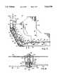
- FIG. 3is a cross-sectional view taken along line 3--3 of FIG, 2.
- FIG. 4is a partial perspective view illustrating reinforcing liners used on the interior of the vehicle of FIG. 1.
- FIG. 5is a partial perspective view illustrating other reinforcing liners used on the interior of the vehicle of FIG. 1.
- FIG. 6is a side elevation of a left front door illustrating the abutments and latches in accordance with the principles of the present invention.
- FIG. 6Ais a cross-sectional view taken along line 6A--6A of FIG. 6 showing the door in an open position and the latch in an unclosed position.
- FIG. 6Bis a view similar to FIG. 6A illustrating the latch of FIG. 6A in the closed position.
- FIG. 7is a side elevation of a right rear door illustrating the abutments and latches in accordance with the principles of the present invention.
- FIG. 8is an enlarged cross-sectional view of the encircled section 8--8 of FIG. 1.
- FIG. 9is a cross-sectional view taken along line 9--9 of FIG. 2.
- FIG. 1one model of a HMMWV 20 often used by the military is illustrated.
- the vehiclehas a chassis, including longitudinal frame rails 22 that extend substantially the full length of the vehicle.
- the engine drive train and suspension(not shown), including the wheels 24, are mounted to the chassis.
- a central tunnel structure 26extends longitudinally in the central portion of the vehicle between the frame rails 22.
- a protective system 28 shown in a disassembled perspective in FIG. 2is designed to protect occupants in the passenger compartment 30 from the forces of a mine blast that is triggered or detonated by one of the pair of front wheels 24 or the pair of rear wheels 25.
- the system 28 illustrated in FIGS. 1-6, 8is applied to the left side of the body structure of the vehicle 20.
- the right side body structure of the vehicle 20is almost an identical mirror image of the left side body structure. Therefore, in the preferred embodiment of the invention, the protective system 28 as is described and illustrated with respect to the body structure on the left hand side of the vehicle is also applied to the body structure of the right hand side of the vehicle.
- the discussion to followassumes that the left front wheel 24 detonates the mine. In that event, a forward portion of the passenger compartment 30, for example, forward compartment 32, is most at risk.
- the blast forces inflicting the greatest damageare those forces 34 that are normal to or substantially perpendicular to the vehicle surfaces, for example, the lower-forward surfaces 36, 38 of the forward portion 32 of the passenger compartment 30.
- blast forces which are oblique to the vehicle surfaces they impactare more readily deflected by those surfaces and are less likely to cause severe damage to the vehicle.
- the protective system 28is designed to absorb some of the blast forces impacting the forward portion 32 of the passenger compartment 30; however, the system 28 must minimize deformation of the lower-forward surfaces 36, 38 so as to minimize injury to the lower legs and feet of the occupant. Therefore, the system 28 functions to transfer the blast forces 34 around the boundaries, or periphery of the forward portion 32 and into the more rigid structural members of the vehicle 20.
- the shield structure 44is designed to experience minimal deflection and deformation to minimize the deformation of the lower-front walls 36, 38 of the forward portion 32.
- the major function of the shield 44is to transfer the blast forces 34 through the walls surrounding the forward portion 32 and into other structural members of the vehicle 20.
- the shield 44transfers blast forces from its lateral edges into outer and inner reinforcing liners or plates 48, 50, respectively, (FIGS. 4 and 5).
- the outer reinforcing plate 48transfers the blast forces it receives from the shield 44 into a forward column or upright reinforcement 52 associated with what is generally known as the A-pillar of the vehicle 20.
- the blast forcesare also transferred from an upper edge of the shield 44 through a protective plate 54 and an upper or interconnecting plate 56, which are rigidly attached together and between the upper edge of the shield 46 and a rigid cross member of the vehicle shown generally at 58.
- a lower protective plate 60transfers blast forces from a lower edge of the shield 44 to the vehicle body structure to which the lower protective plate 60 is bolted.
- the part of the system 28 thus far describedis highly effective at routing and transferring the blast forces 34 through the shield 44 and around the forward portion 32 of the passenger compartment 30. Consequently, the shield 44 experiences minimal deformation and protects the lower-forward surfaces 36, 38 which are in a direct line with the most destructive of the blast forces.
- the protective system 28effectively redistributes the forces resulting from the exploding mine and received by the shield structure 44 away from the lower-forward surfaces 36, 38 of the forward portion 32 to the more rigid vehicle structural members, for example, the pillars 52, 68, 78.
- the system 28 of the preferred embodimentis highly effective at minimizing deformation of the forward portion 32 of the passenger compartment 30 and, in addition, protects the passenger compartment 30 from the blast forces.
- the performance of the protective system 28can be further improved by transferring blast forces from the A-pillar reinforcement 52 to a first abutment 62, rigidly mounted on the inner side of a front door 64, shown in phantom in FIG. 1.
- the first abutment 62is mounted adjacent the forward edge of the door 64 and in juxtaposition with a rearward edge of the A-pillar reinforcement 52.
- the front door 64transfers the blast forces to a second abutment 66 mounted on the inner surface adjacent its rearward edge and is in immediate juxtaposition with a second reinforced column or upright which is generally known as the B-pillar 68.
- the abutments 62, 66 on the door 64transfer the blast forces from the A-pillar reinforcement 52, across the door 64 and into the B-pillar 68. That transfer of forces is facilitated by the use of auxiliary, heavy duty latches 70 which secure the front door 64 in its closed position during the blast.
- the rear door 72shown in phantom in FIG. 1, has a first abutment 74 mounted on an inner surface and adjacent its forward edge in juxtaposition with a rearward edge of the B-pillar 68.
- a second abutment 76is mounted on the inner surface and adjacent the rearward edge of the rear door 72 in juxtaposition with a rear or C-pillar 78.
- heavy duty latches 80are used to prevent the rear door 72 from opening during the blast. Consequently, the rear door 72 functions to transfer blast forces from the B-pillar 68, across the rear door 72, to the C-pillar 78 and into the rear structure 82 of the vehicle 20. Therefore, in this embodiment of the invention, the system 28 effectively redistributes the blast forces from the A-pillar reinforcement 52 across the front door 64 to the B-pillar 68 across the rear door 72 and into the rear structure of the vehicle 82.
- the protective system 28includes a rear underbody protective plate structure 84, which is bolted to the forward underbody protective plate structure 46, as well as the vehicle structure located behind the B-pillar 68. in this further embodiment, the protective system 28 effectively transfers the blast forces along the lower structure of the vehicle. The result of the use of the entire protective system 28 is to distribute the blast forces through the side and bottom portions of the vehicle structure that surrounds the passenger compartment 30, thereby protecting the occupants in the passenger compartment 30 from the blast forces.
- the most important part of the protective system 28, that is, the portion of the system 28 that maintains the integrity of and, minimizes damage to, the forward portion 32 of the passenger compartment 30includes the forward underbody protective plate structure 46, the shield structure 44, the outer plate 48 and the inner plate 50.
- the shield structure 44is fabricated on a lower-forward section of the protective plate structure as shown in to FIG. 3.
- the shield structure 44includes a lower-forward section of plate 90 of the plate structure 46.
- the protective plate 90is located between a bottom protective plate 60 and a forward protective plate 94.
- the plates 60, 90, 94are preferably made from a high hardness, wrought, steel armor plate approximately 0.140 inches thick per MIL-A-46177 and together form an underbody base plate 96 portion of the forward underbody protective plate structure 46.
- the shield 44further includes a plurality of reinforcing elements, preferably, structural steel tubes 100 and an inner reinforcing shield plate 102 that preferably, are rigidly connected to the armor plate 90.
- the tubesare welded to an upper surface of the plate section 90 and a lower surface of the shield plate 102.
- the tubesextend substantially over the full width of the plate section 90 and are preferably oriented to be parallel with each other to permit a desired minimal deformation of the shield structure 44 in response to the blast forces.
- the shield assembly 44is fabricated to form a beam structure that in response to the blast forces, places a side closer to the blast in compression and an opposite side in tension.
- the tubes 100are preferably manufactured from a structural steel tube of a ASTM A500 GR B material having a wall thickness of approximately 0.125 inches.
- the plate 102is preferably positioned parallel to plate 90 and is welded to the tubes 100, the bottom plate 60 and forward plate 94.
- the plate 102is preferably made of 4130 RC 39-42 steel approximately 0.100 inches thick.
- Upper and lower reinforcing spacers or wedges 104, 106, respectively,are U-shaped channels and are welded at the lateral edges of the plate 102 and function to space the plate 102 from the wall sections 36, 38.
- the reinforcing wedges 104, 106have respective upper sides 108, 110 that are shaped to provide a bearing surface against the forward surface 112 of the sheet metal body structure 114 of the vehicle 20.
- the reinforcing spacersare preferably made of ASTM A500 GR B structural steel tube having a wall thickness of approximately 0.250 inches.
- the shield structure 44may also include other reinforcing structure, for example, an angle strip 116 that extends laterally across the intersection of the plates 60 and 102 and is welded to the plates 60, 102 to provide additional rigidity.
- the left side reinforcing plate 48includes a side plate 122 having a mounting flange 124 extending over the rearward edge of the plate 122.
- a reinforcing element 126has a side plate 128 welded to the side plate 122.
- the reinforcing element 126also includes a mounting flange 130.
- the left side reinforcing plate 48is preferably made from aluminum 5083 H321.
- the primary liner element 122is preferably 0.375 inches thick, and the element 126 is approximately 0.250 inches thick.
- FIG. 5illustrates the left side inner reinforcing plate 50.
- the reinforcing plate 50includes a side reinforcing plate 134 having a gusset 136 and a lower mounting flange 137.
- a reinforcing element 138has a side plate 140 that is welded to the side plate 134.
- the reinforcing element 136further includes a mounting flange 142 extending along the forward edge of element 136, and a second mounting flange 144 extending along the lower edge of reinforcing element 136.
- the left side inner reinforcing plate 50is preferably made of the same material as the reinforcing plate 48.
- the A-pillar reinforcement 52is illustrated in more detail and includes a unitary structure having a center body column or upright 146, an L-shaped forward column 148 extending along a forward edge of center column 146 and an L-shaped rear column 150 extending along a rear edge of center column 146.
- the A-pillar reinforcement 52is mounted on an upper surface of a bottom section 151 of the vehicle body 114 by fasteners 152.
- the A-pillar reinforcement 52is preferably made of aluminum 6061-T6 extrusion that meets 6061-T6 to a depth of 0.500 inches and must meet at least a 6061-T5 at depths greater than 0.500 inches.
- the above described elementsincluding the forward underbody structure 46 with its integral shield 44, the outer reinforcing plate 48, the inner reinforcing plate 50, and the A-pillar reinforcement 52 are connected to the body structure 114 of the vehicle 20 such that those components with the body 114 form an integral unitary structure.
- the above described elementsincluding the forward underbody structure 46 with its integral shield 44, the outer reinforcing plate 48, the inner reinforcing plate 50, and the A-pillar reinforcement 52 are connected to the body structure 114 of the vehicle 20 such that those components with the body 114 form an integral unitary structure.
- fastenerssuch as nuts and bolts 160 extend through an outer corner flange 162, the plate 90, reinforcing plate 102, the flanges 108, 110 of respective reinforcing wedges 104, 106, through the vehicle body 114, and through the mounting flange 130, which abuts against an inner surface of the body 114 and is an integral part of the outer reinforcing plate 48.
- the reinforcing wedges 104, 106 illustrated in FIG. 3are located along the outer lateral edge of the shield structure 44. There are corresponding reinforcing wedges along the inner lateral edge of the shield structure Further, as illustrated in FIG.
- fasteners 160along the inner lateral edge of the shield structure that extend through the mounting flange 142 of the inner reinforcing plate 50, the vehicle structure 114, flanges of reinforcing wedges that are similar to the flanges 108, 110 of wedges 104, 106, reinforcing plate 102, and plate 90. Therefore, the fasteners 160 are effective to fasten the above elements together to form a unitary rigid structure. Referring to FIGS. 2, 3, and 5, fasteners, such as nuts and bolts 164 extend through the lower flange 137 of the inner reinforcing plate 50, the vehicle body 114 and the channel 166 of the forward underbody structure 46.
- the rear side of the outer reinforcing plate 48is also rigidly connected to the forward column 148 of the A-pillar reinforcement 52 by bolts or other fasteners 168 that extend through the rear mounting flange 124 of the outer reinforcing plate 48 and are threaded into the forward column 148.
- the left side of the vehicle structure 114 of the forward portion 32extends over the outer surface 171 of the center column 146 of the A-pillar reinforcement 52.
- a left side wall armor or protective plate 172is mounted over the left side vehicle structure 114 and inside the corner flange 162.
- a first plurality of fasteners 174extend through the corner flange 162, through the side wall plate 172, through the left side of vehicle structure 114 and through the side plate 122 (FIG. 4) of the outer reinforcing plate 48.
- Another group of fasteners 174extend through the plate 172, the left side vehicle structure 114, and the side plate 122 (FIG. 4) of the outer reinforcing plate 48.
- the interconnection of the plate 172 left side vehicle structure 114 and side plate 122provides a very rigid construction for the side wall of the forward portion 32.
- fastenerssuch as threaded bolts 175 extend through the side plate 134 of the inner reinforcing plate 50 and through a side wall of the tunnel 26. That connection increases the rigidity of the inner side wall 176 of the forward portion 32.
- the forward underbody protective plate structure 46contains an outer side flange 173.
- Fasteners 178for example, nuts and bolts, extend through holes in flange 173 through the left side vehicle structure 114 to rigidly connect the outer lateral edge of the forward underbody plate structure 46 to the vehicle 20.
- the inner lateral edges of the forward and rear underbody plate structures 46, 84contain openings 179. Referring to FIGS. 2, 4 and 5, a lower portion of the vehicle body structure 114 is protected and made more rigid by fastening it between outer protective plates 155, preferably of steel and inner metal liners 157.
- a bracket 180is attached to the frame rail 22 using band straps 181 or alternatively, adhesive, rivets or other fasteners.
- the bracket 180has a boss 182 extending from its lower surface and into the opening 179.
- the boss 182is shaped to that there is a clearance or space between the outer periphery of the boss and the periphery of the opening 179.
- a retainer 183is connected to the lower side of the boss with a screw or other fastener 184. With this construction, the lower surface 185 of the respective front and rear underbody structure 46, 84 is carried on the upper surface 186 of the retainer 183.
- the inner lateral edges of the forward and rear underbody plate structures 46, 84are suspended from and able to move with respect to the frame rails during the normal operation of the vehicle 20.
- the suspended mountinghelps to prevent excessive stresses and forces from being applied to the frame rails 22.
- the above described construction and interconnection of the shield structure 44 and forward underbody plate structure 46, outer reinforcing plate 48, inner reinforcing plate 50 and A-pillar reinforcement 52provides a rigid unitary structure with the existing vehicle body to minimize damage and deformation to the forward portion 32 of the passenger compartment 30.
- the shield structure 44is primarily effective to transfer the blast forces to its periphery and upwardly and rearwardly through the vehicle structure. The forces along the lateral edges are transferred across the reinforcing wedges 104, 106 through the vehicle body sections 36, 38 across the internal outer and inner reinforcing plates 48, 50, respectively and to either the central tunnel structure 26 or the A-pillar reinforcement 52.
- the blast forcescan be further distributed to other structures of the vehicle.
- fasteners 187are used to fasten one section 188 of a door hinge 189 to the A-pillar reinforcement 52.
- the fastenersextend through the hinge section 188, the plate 172, a spacer 190, the left side vehicle structure 114 and through the center body 146 of the A-pillar reinforcement 52.
- the other hinge section 191is bolted on to the edge of the front door 64 as illustrated in FIG. 6.
- the door 64includes first abutment blocks 62 that are bolted or welded to an interior surface of the door 62 along its forward edge. As shown in FIG. 1, when the door is closed, the blocks 62 are located immediately adjacent the L-shaped rear column 150 of the A-pillar reinforcement 52. Consequently, as the forces of the blast are transferred rearwardly and upwardly around the forward portion 32 and into the A-pillar reinforcement 52 and plate 172, the rear edge of plate 172 is pushed into contact with the forward blocks 62, thereby transferring a portion of the blast forces to the forward abutment blocks 62.
- the door 64is normally constructed of an outer protective plate, for example, armor plate, 193 and a composite liner 194 that overlays and is connected to an inner surface of the protective plate 193.
- Second abutment angle blocks 66in the form of an aluminum extrusion are mounted on the inner surface near the rearward edge of the protective plate 193 of the front door 64.
- the angle blocks 66function as force transfer blocks.
- the protective system 28uses the front door 64 to transfer blast forces from the A-pillar reinforcement 62 and plate 172 to the forward blocks 62, across the door 64 to the second abutment angle blocks 66 and to the B-pillar 68. Transferring the blast forces around the side walls of the passenger compartment 30 and rearwardly along the vehicle further preserves the mechanical integrity of the passenger compartment 30 and further reduces the risk of injury to the occupants of the passenger compartment.
- the latch 70includes two pivoting latch arms 196, which are pivotally mounted at upper and lower locations adjacent the rear edge of the door 64.
- the latch arms 196are coupled to connecting rods 198, which, in turn, are operatively connected to an operating handle 200. Lifting the handle 200 moves the connecting links 198 generally downward, thereby pivoting the latch arms 196 about pivot pins 202.
- each of the latch arms 196pivots out beyond the rear edge 203 of the door 64 and extend behind an inner surface 204 of a respective latch block 206 of the B-pillar 68.
- the latch blocks 206are welded or otherwise rigidly connected to a metal liner 207 of the B-pillar 68. Moving the latch arm 196 behind the latch block 206 of the B-pillar positively stops and blocks the front door 64 from opening during the blast.
- fasteners 208extend through one side 210 of hinge 212, through the outer protective plate 214, and through a reinforcement channel 224 of the B-pillar 68.
- fasteners 216are used to connect the other side 218 of the hinge 212 to the forward edge of the rear door 72.
- the rear door 72is preferably constructed in a known manner similar to the front door 64 with an outer protective or armor plate connected to an inner composite liner.
- the protective system 28uses the rear door to facilitate the transfer of the blast forces from the B-pillar 68 to the C-pillar 78 (FIG. 1) of the vehicle 20,
- the forward abutment blocks 74 on the rear door 72are located in a spaced apart relationship along the forward edge 222 of the rear door 72.
- the blocks 74are positioned to be immediately adjacent the rearward edge of the B-pillar 68 when the door 72 is closed.
- the rear abutment angle blocks 76 on the door 72are comparable in shape to the angle blocks 66 on the front door 64.
- the angle blocks 76are mounted in the inner surface and along the rear edge 228 of the protective plate of the door 72.
- the angle blocks 76have an outwardly extending flange that is positioned to be adjacent the C-pillar 81.
- the C-pillar 81is constructed of a protective outer plate and an inner metal liner in the same manner as described with respect to the B-pillar 68.
- the rear door 72 illustrated in FIG. 7is a right side rear door, and the construction and latches on the left side rear door 72 of FIG. 1 is comparable.
- an auxiliary latch system 80is comprised of two latch arms 230 pivotally mounted adjacent the rear edge 228 of the door 72. Connecting links 232 operatively connect the latch arms 230 to an operating handle 234. Moving the handle 234 in a generally upward direction moves the connecting links 232 generally downward, thereby pivoting latch arms 230 about the pivot pins 236.
- the latch arms 230are pivoted out beyond the rear edge 228 and located behind a latch block on the rear side of a metal liner of the C-pillar 81 which is comparable to the metal liner 207 of the B-pillar 68.
- the protective system 28transfers the blast forces from the front of the vehicle upwardly and rearwardly through the sides of the passenger compartment to structure at the rear of the vehicle, thereby minimizing deformation and damage to the sides of the passenger compartment and reducing the risk of injury to the occupants therein.
- a rear underbody protective plate structure 84is connected along its forward edge 242 to the rearward edge 244 of the front underbody plate structure 46 and to the vehicle body 114 as shown in FIG. 8.
- a structural aluminum tube 246extends between the lateral edges of the structures 46, 84.
- the tube 246is fastened to the vehicle structure 114 by means of a bolt 248 extending through a reinforcing washer plate 250 into a nut 252, for example, an upset nut, that extends through a top wall of the tube 246.
- a threaded fastener 254extends through washer 256 through holes 258, 260 in the respective plate structures 46, 84 through a sleeve 262 and is threaded into a nut 263, also preferably an upset nut.
- a block of resilient material 264for example, rubber, surrounds the sleeve 262 and extends between the lower wall of the tube 246 and the upper surface of the plate structure 84.
- the holes 258, 260 in the respective plate structures 46, 84are larger than the outer diameter of the sleeve 262.
- the above structurefunctions to resiliently connect the forward underbody structure 246 to the rear underbody plate structure 84. Consequently, during normal operation of the vehicle, the structures 46, 84 can independently move with respect to each other.
- blast forces being carried by the forward underbody plate structure 46will, to some extent, be absorbed by the resilient material 264 and by the energy required to move the forward underbody structure up against the forward side of the sleeve 262 and, in turn, move the rear side of the sleeve 262 against the forward edge of the hole 260 within the rear underbody plate structure 84. Therefore, the structure illustrated in FIG. 8 absorbs some of the blast forces and thereafter transfers the blast forces to the rear underbody structure of the vehicle.
- the rear underbody structure 84is also connected to the structure of the vehicle in a manner as earlier described with respect to the front plate underbody structure 46.
- the description of the system for the vehicle 20has focused on a protective system 28 associated with the left side of the vehicle.
- the protective system 28 described with respect to the left sidethat includes the forward and rear underbody protective plate structures 46, 84, including the shield structure 44, the reinforcing plates 48, 50 and the A-pillar reinforcement 52, the abutments 62, 64, 74, 76 and latches 70, 80 and the front and rear doors 64, 72 that function to protect the passenger compartment 30 on the left side of the vehicle is preferably also applied to the right side of the vehicle.
- the specific geometry size and shape of the forward underbody plate structure 46will have to be altered to accommodate those individual differences between the left and right sides of the vehicle.
- the exact size and shape of the plates 48, 50 which are made for the right side of the vehiclewill be slightly different in size and shape than those designed and manufactured for the left side of the vehicle.
- the function and operation of the forward system protecting the forward portion 32 on the left and right sides of the vehicleis identical.
- the protective system 28 on the left side of the vehicleit is believed that one who is skilled in the art can manufacture a functionally comparable protective system for the right side of the vehicle that will vary slightly in size and shape to accommodate the different physical structures on the right side of the vehicle.
- the front and rear doors and B and C pillars of the right side of the vehiclewill be constructed identically as described and illustrated with respect to the left side of the vehicle to help transfer and distribute the blast forces along the right side of the passenger compartment 30 across the doors and to their respective pillars.
- the various metal plates and piecesare preferably rigidly connected together by welding processes.
- the geometry of the weldis determined by engineering analysis, and welding standards and specifications are determined from published standards of the American Welding Society and from the military standards and specifications published in association with the specifications for the various materials selected. Those who are skilled in the art can use that information to determine various welding procedures and processes that satisfy both the desired weld geometry and the published welding standards and specifications.
- the protective system described hereinmay take several forms depending on how it is to be integrated into the vehicle structure.
- the system 28 described hereinmay be part of a major retrofit of the HMMWV during which the system 28 and other armor or protective plates are added to the vehicle structure. It is preferable in the design of the system 28 to use originally manufactured parts to reduce the parts inventory. Further, the design should permit the system to be repaired in the field.
- the major portion of the system 28may be manufactured as a component of a kit that is applied to the vehicle in the field.
- the system 28would include the forward and rear underbody protective plate structures 46, 84 with the forward underbody structure 46, including the shield 44.
- the kitwould also include the reinforcing plates 48 and 50 and the A-pillar reinforcement 52.
- One skilled in the art of vehicle armor designcould readily adapt those components to make them suitable for use in a field installed kit based on the description of the components contained therein.
- the shield structurecan also fabricated so that the plurality of elements is only rigidly connected to one of the adjacent plates.
- the plurality of reinforcing elementscan take the form of tubes, U-shaped members or even solid shafts providing the desired mechanical function within the shield structure.
- the parallel arrangement of the reinforcing elementscan be replaced by other arrangements, for example, a starburst arrangement, so that the desired function of the shield structure is obtained.
- various spacersare described as having a U-shaped configuration, such spacers could also be fabricated from tubing or comparable elements.
Landscapes
- Engineering & Computer Science (AREA)
- General Engineering & Computer Science (AREA)
- Body Structure For Vehicles (AREA)
Abstract
Description
Claims (37)
Priority Applications (1)
| Application Number | Priority Date | Filing Date | Title |
|---|---|---|---|
| US08/658,239US5663520A (en) | 1996-06-04 | 1996-06-04 | Vehicle mine protection structure |
Applications Claiming Priority (1)
| Application Number | Priority Date | Filing Date | Title |
|---|---|---|---|
| US08/658,239US5663520A (en) | 1996-06-04 | 1996-06-04 | Vehicle mine protection structure |
Publications (1)
| Publication Number | Publication Date |
|---|---|
| US5663520Atrue US5663520A (en) | 1997-09-02 |
Family
ID=24640468
Family Applications (1)
| Application Number | Title | Priority Date | Filing Date |
|---|---|---|---|
| US08/658,239Expired - LifetimeUS5663520A (en) | 1996-06-04 | 1996-06-04 | Vehicle mine protection structure |
Country Status (1)
| Country | Link |
|---|---|
| US (1) | US5663520A (en) |
Cited By (115)
| Publication number | Priority date | Publication date | Assignee | Title |
|---|---|---|---|---|
| DE19913845A1 (en)* | 1999-03-26 | 2000-09-28 | Henschel Wehrtechnik Gmbh | System for protecting armoured cars and tanks against effects of mines comprises protective shield consisting of steel plate mounted at distance from bottom of the vehicle with mounting containing energy absorbing component |
| EP1081451A3 (en)* | 1999-07-31 | 2001-03-14 | Henschel Wehrtechnik GmbH | Device mounted on a vehicle, especially a military tracked vehicle |
| US6363830B1 (en)* | 2000-03-06 | 2002-04-02 | The United States Of America As Represented By The Secretary Of The Army | Door structure for mine protection |
| DE10117575A1 (en)* | 2001-04-07 | 2002-10-10 | Krauss Maffei Wegmann Gmbh & C | Device for protecting the crew of a military vehicle in the event of a mine explosion |
| DE10145279A1 (en)* | 2001-09-14 | 2003-04-24 | Rheinmetall Landsysteme Gmbh | Safety floor in armored vehicles |
| WO2003062735A1 (en)* | 2002-01-24 | 2003-07-31 | Krauss-Maffei Wegmann Gmbh & Co. Kg | Armoured vehicle, especially a combat tank |
| US6609748B1 (en)* | 2000-09-25 | 2003-08-26 | Ford Global Technologies, Llc | Forward facing rear door assembly for motor vehicles |
| US6619729B2 (en)* | 2001-06-07 | 2003-09-16 | Mazda Motor Corporation | Side body structure of vehicle |
| US6679546B2 (en)* | 2001-06-12 | 2004-01-20 | Mazda Motor Corporation | Front body structure of vehicle |
| US20050022658A1 (en)* | 2002-07-12 | 2005-02-03 | Kyle Bateman | Modular ballistic wall |
| EP1564520A3 (en)* | 2004-02-05 | 2005-08-24 | Steyr-Daimler-Puch Spezialfahrzeug AG & Co. KG | Hull structure of an armored vehicle with protection against landmines |
| US6952990B1 (en) | 2002-09-16 | 2005-10-11 | Niitek Inc. | Land mine overpass tread design |
| US20050252113A1 (en)* | 2002-07-24 | 2005-11-17 | Jean-Christopher Duclos | Sandwich structure |
| US20050257679A1 (en)* | 2004-02-11 | 2005-11-24 | Rheinmetall Landsysteme Gmbh | Mine protection vehicle system |
| US20050284682A1 (en)* | 2004-02-11 | 2005-12-29 | Rheinmetall Landsysteme Gmbh | Vehicle protection against the effect of a land mine |
| US20060056946A1 (en)* | 2004-07-08 | 2006-03-16 | Danlel Benisti | Truck cabin armor |
| US7114764B1 (en)* | 2004-04-22 | 2006-10-03 | The United States Of America As Represented By The Secretary Of The Navy | Mine and collision protection for passenger vehicle |
| US20070017360A1 (en)* | 2003-09-22 | 2007-01-25 | Michael Cohen | Modular armored vehicle system |
| US20070069472A1 (en)* | 2001-12-12 | 2007-03-29 | Spencer Lambert | Bullet containment trap |
| US20070094943A1 (en)* | 2003-09-26 | 2007-05-03 | Ulf Deisenroth | Modular shelter system, particularly for transport of persons and/or objects |
| US20070152473A1 (en)* | 2005-12-16 | 2007-07-05 | Ford Motor Company | Independently opening doors for an automotive door opening |
| USD548646S1 (en)* | 2005-12-29 | 2007-08-14 | Force Protection Industries, Inc. | Armored vehicle or toy replica |
| USD548647S1 (en)* | 2005-12-29 | 2007-08-14 | Force Protection Industries, Inc. | Armored vehicle or toy replica |
| USD548648S1 (en)* | 2006-02-14 | 2007-08-14 | Force Protection Industries, Inc. | Armored vehicle or toy replica |
| US20070186762A1 (en)* | 2005-12-22 | 2007-08-16 | Blackwater Lodge And Training Center Llc | Armored vehicle with blast deflecting hull |
| USD552507S1 (en)* | 2006-02-14 | 2007-10-09 | Force Protection Industries, Inc. | Armored vehicle or toy replica |
| WO2008003296A1 (en)* | 2006-07-05 | 2008-01-10 | Kraus-Maffei Wegmann Gmbh & Co. Kg | Vehicle, particularly military vehicle, protected against the effect of an external explosion |
| US20080017426A1 (en)* | 2006-03-23 | 2008-01-24 | Walters Raul J | Modular vehicle system and method |
| US20080066613A1 (en)* | 2006-09-15 | 2008-03-20 | Lockheed Martin Corporation | Perforated hull for vehicle blast shield |
| WO2007088071A3 (en)* | 2006-02-04 | 2008-04-17 | Acs Armoured Car Systems Gmbh | Armored vehicle body |
| DE102006052609A1 (en)* | 2006-11-08 | 2008-05-15 | Krauss-Maffei Wegmann Gmbh & Co. Kg | Mine-protected, in particular military vehicle |
| US7389718B1 (en) | 2005-09-23 | 2008-06-24 | Carter Gerald D | Ballistic blanket |
| US7393045B1 (en) | 2006-01-17 | 2008-07-01 | The United States Of America As Represented By The Secretary Of The Army | Two-piece armored cab system |
| US20080173167A1 (en)* | 2006-09-15 | 2008-07-24 | Armor Holdings | Vehicular based mine blast energy mitigation structure |
| USD580825S1 (en)* | 2005-12-29 | 2008-11-18 | Force Protection Technologies, Inc. | Armored vehicle or toy replica thereof |
| US20090025547A1 (en)* | 2005-08-17 | 2009-01-29 | Kocher Robert W | Highly survivable urban utility vehicle (HSUUV) |
| US20090037049A1 (en)* | 2007-07-31 | 2009-02-05 | Clodfelter James F | Damage control system and method for a vehicle-based sensor |
| WO2006011903A3 (en)* | 2004-06-29 | 2009-04-02 | Tony Piscitelli | Asymmetric composite materials |
| US20090108628A1 (en)* | 2007-10-31 | 2009-04-30 | Caterpillar Inc. | Vehicle cab floor protection system |
| USD593450S1 (en)* | 2005-12-29 | 2009-06-02 | Force Protection Industries, Inc. | Armored vehicle |
| USD596917S1 (en) | 2008-04-24 | 2009-07-28 | Trimark Corporation | Blast lock handle |
| US20090267354A1 (en)* | 2008-04-24 | 2009-10-29 | Trimark Corporation | Unitary latch, blast lock, and release handle assembly for vehicle door |
| WO2009155965A1 (en) | 2008-06-23 | 2009-12-30 | Klaus Ackermann | Armor for a motor vehicle |
| US20100024633A1 (en)* | 2004-11-01 | 2010-02-04 | Anthony Piscitelli | Articles, manufactures, and assemblies utilizing configured and sized plates comprised of penetration-proof laminated constructs formed of asymmetric composite materials |
| US20100037761A1 (en)* | 2004-04-16 | 2010-02-18 | Bae Systems Survivability Systems, Llc | Lethal Threat Protection System For A Vehicle And Method |
| US7683821B1 (en) | 2006-10-25 | 2010-03-23 | Niitek, Inc. | Sensor sweeper for detecting surface and subsurface objects |
| US20100077913A1 (en)* | 2005-12-20 | 2010-04-01 | Armor Holdings, Inc. | Modular body for use on an armored vehicle |
| US20100083819A1 (en)* | 2007-07-24 | 2010-04-08 | Thomas Mann | Armor system |
| USD615383S1 (en) | 2009-03-13 | 2010-05-11 | Trimark Corporation | Blast lock handle with bent tip |
| USD615841S1 (en) | 2009-03-13 | 2010-05-18 | Trimark Corporation | Blast lock handle with angled body |
| US7770506B2 (en) | 2004-06-11 | 2010-08-10 | Bae Systems Tactical Vehicle Systems Lp | Armored cab for vehicles |
| US7775526B1 (en) | 2001-12-12 | 2010-08-17 | Action Target Inc. | Bullet trap |
| US20100242714A1 (en)* | 2004-11-01 | 2010-09-30 | Anthony Piscitelli | Anti-ballistic egress window assembly |
| US20100251883A1 (en)* | 2009-04-07 | 2010-10-07 | Plasan Sasa Ltd. | Safety apparatus for providing protection against an explosion and vehicle comprising same |
| US20100261106A1 (en)* | 2009-04-08 | 2010-10-14 | Canon Kabushiki Kaisha | Measurement apparatus, exposure apparatus, and device fabrication method |
| WO2010116361A1 (en)* | 2009-04-05 | 2010-10-14 | Rafael Advanced Defense Systems Ltd. | Armoring combatants' compartment in a wheeled vehicle against explosive charges |
| WO2010123606A1 (en)* | 2009-01-29 | 2010-10-28 | Lockheed Martin Corporation | Blast resistant vehicle hull |
| US20100311015A1 (en)* | 2004-12-30 | 2010-12-09 | Addison Sovine | Training door |
| US20100307329A1 (en)* | 2009-06-05 | 2010-12-09 | Robert Kaswen | Methods and apparatus for suspending a vehicle shield |
| US20100319525A1 (en)* | 2007-07-05 | 2010-12-23 | Pavon John J | System and Method for Protecting Vehicle Occupants |
| US7878104B2 (en) | 2005-09-30 | 2011-02-01 | Armor Holdings, Inc. | Armored shell kit and associated method of armoring a vehicle |
| DE102009034941A1 (en)* | 2009-07-28 | 2011-02-03 | Edag Gmbh & Co. Kgaa | Vehicle armor for e.g. passenger car, has adapter structure that is adjusted to form body structure and fastened to body structure by gluing, and armoring structure fastened to adapter structure |
| US20110067513A1 (en)* | 2009-09-24 | 2011-03-24 | Ryan Wilson | Gear box assembly for rotating turret system |
| US20110079134A1 (en)* | 2008-06-12 | 2011-04-07 | Nexter Systems | Floor protection device for vehicle cab |
| EP2325595A2 (en) | 2009-11-23 | 2011-05-25 | Plasan Sasa Ltd. | Floor protection |
| US20110148147A1 (en)* | 2009-12-18 | 2011-06-23 | Tunis George C | Vehicle with structural vent channels for blast energy and debris dissipation |
| US7997182B1 (en)* | 2007-08-16 | 2011-08-16 | Timothy J. Cox | Protective hull for vehicles |
| EP2362041A1 (en)* | 2010-02-19 | 2011-08-31 | Krauss-Maffei Wegmann GmbH & Co. KG | Mine safety lock for assembly on doors of military vehicles |
| US20110219944A1 (en)* | 2010-03-10 | 2011-09-15 | Oto Melara S.P.A. | Vehicle provided with revolving turret |
| DE102010016605A1 (en)* | 2010-04-23 | 2011-10-27 | Krauss-Maffei Wegmann Gmbh & Co. Kg | Floor pan of a vehicle, in particular an armored military vehicle, and additional armor for a floor pan |
| US20110272968A1 (en)* | 2010-05-05 | 2011-11-10 | Medwell Roger Terence Arthur | Vehicle |
| US8066319B2 (en)* | 2006-12-01 | 2011-11-29 | Bae Systems Land & Armaments, L.P. | Vehicle emergency egress assembly |
| US20110314999A1 (en)* | 2010-06-23 | 2011-12-29 | International Truck Intellectual Property Company, Llc | Vehicle armor |
| US8091933B1 (en) | 2007-09-21 | 2012-01-10 | Trimark Corporation | Heavy duty door latch and release modules |
| US8096225B1 (en) | 2007-11-16 | 2012-01-17 | BAE Systems Tactical Vehicle Systems L.P. | Armored cab for vehicles |
| WO2012047227A1 (en)* | 2010-10-08 | 2012-04-12 | Navistar Canada, Inc. | Auto-reset belly for a military vehicle |
| US20120139293A1 (en)* | 2006-12-01 | 2012-06-07 | Antonich Gary L | Universal latch mechanism |
| US20120186428A1 (en)* | 2008-10-24 | 2012-07-26 | Gregory Lucas Peer | Blast energy absorption system |
| US20120193940A1 (en)* | 2009-12-18 | 2012-08-02 | Tunis George C | Vehicle with structural vent channels for blast energy and debris dissipation |
| DE102011000974A1 (en)* | 2011-02-28 | 2012-08-30 | Krauss-Maffei Wegmann Gmbh & Co. Kg | Vehicle, in particular military vehicle |
| US8267003B1 (en) | 2009-08-11 | 2012-09-18 | Armorworks Enterprises LLC | Blast resistant armor mounting hardware |
| US8374754B2 (en) | 2005-12-05 | 2013-02-12 | Niitek, Inc. | Apparatus for detecting subsurface objects with a reach-in arm |
| US20130062486A1 (en)* | 2011-09-09 | 2013-03-14 | Amikam Shmargad | Common mounting provisions for an armored vehicle |
| US8418597B2 (en) | 2007-07-05 | 2013-04-16 | John J. Pavon | System and method for protecting vehicle occupants |
| US8418596B2 (en) | 2007-07-05 | 2013-04-16 | John J. Pavon | System and method for protecting vehicle occupants |
| US8465062B2 (en) | 2007-08-20 | 2013-06-18 | The Eastern Company | Armored vehicle door hardware providing access, egress, rescue and security |
| EP2138801A3 (en)* | 2008-06-25 | 2013-07-24 | Plasan Sasa Ltd | Armour construction for armoured vehicles |
| US8596182B2 (en) | 2007-06-20 | 2013-12-03 | Foster-Miller, Inc. | Spall liner |
| US8627757B2 (en) | 2009-11-23 | 2014-01-14 | Plasan Sasa Ltd. | System for providing protection against an explosive threat |
| US8640592B1 (en)* | 2011-03-23 | 2014-02-04 | The Boeing Company | Blast pressure diffuser |
| US8667880B1 (en)* | 2009-05-12 | 2014-03-11 | Granite Tactical Vehicles Inc. | Cabin for a Humvee vehicle |
| US20140137728A1 (en)* | 2012-05-03 | 2014-05-22 | Bae Systems Land & Armaments, L.P. | Buoyant armor applique system |
| US8770086B2 (en)* | 2012-08-31 | 2014-07-08 | International Truck Intellectual Property Company, Llc | Blast protection attachment |
| KR101421125B1 (en)* | 2013-08-09 | 2014-07-18 | 국방과학연구소 | Mine resistance ambush protected vehicle |
| US20140208931A1 (en)* | 2011-09-09 | 2014-07-31 | Amikam Shmargad | Armored vehicle with bolt-on bottom |
| US8943946B1 (en) | 2011-09-27 | 2015-02-03 | Oshkosh Corporation | Energy dissipation system for an armored vehicle having shear fingers and crushable sections |
| US9045014B1 (en) | 2012-03-26 | 2015-06-02 | Oshkosh Defense, Llc | Military vehicle |
| US9163910B2 (en) | 2011-11-22 | 2015-10-20 | Bae Systems Tactical Vehicle Systems Lp | Armored cab for light tactical vehicles |
| US9217623B2 (en) | 2013-03-25 | 2015-12-22 | Action Target Inc. | Bullet deflecting baffle system |
| US9283882B1 (en)* | 2013-02-06 | 2016-03-15 | Armorworks Enterprises LLC | Convertible fighting vehicle |
| US20160265646A1 (en)* | 2014-02-12 | 2016-09-15 | Pratt & Miller Engineering and Fabrication, Inc. | Blast mitigating differential housing |
| USD776003S1 (en) | 2014-11-07 | 2017-01-10 | The United States Of America As Represented By The Secretary Of The Army | Light tactical vehicle hull |
| US10024633B2 (en) | 2016-01-14 | 2018-07-17 | Action Target Inc. | Rapid armor panel system |
| EP3195334B1 (en) | 2014-09-17 | 2018-07-25 | Siemens Aktiengesellschaft | Bullet-resistant electrical installation |
| US10221055B2 (en) | 2016-04-08 | 2019-03-05 | Oshkosh Corporation | Leveling system for lift device |
| US10495419B1 (en)* | 2017-04-27 | 2019-12-03 | Oshkosh Defense, Llc | Vehicle armor systems and methods |
| US10545010B1 (en)* | 2017-04-28 | 2020-01-28 | Oshkosh Defense, Llc | Blast mat configuration |
| US10612893B2 (en)* | 2018-05-15 | 2020-04-07 | Southwest Research Institute | Vehicular external force absorption systems and methods |
| WO2020055362A3 (en)* | 2018-08-17 | 2020-06-04 | Fnss Savunma Si̇stemleri̇ A.Ş. | Floor protection system for armored vehicles |
| US11255642B1 (en)* | 2020-10-07 | 2022-02-22 | Navistar Defense, Llc | Armored vehicle cab |
| US11307001B2 (en)* | 2019-08-13 | 2022-04-19 | Ameren Corporation | Aerial devices having ballistic protection |
| USD966958S1 (en) | 2011-09-27 | 2022-10-18 | Oshkosh Corporation | Grille element |
| US11524728B2 (en)* | 2017-04-27 | 2022-12-13 | Oshkosh Defense, Llc | Cabin assembly |
| US11898824B2 (en) | 2019-08-20 | 2024-02-13 | Advanced Blast & Ballistic Systems Limited | Responding to an explosion local to an armoured vehicle |
| US12098757B1 (en) | 2013-03-10 | 2024-09-24 | Oshkosh Defense, Llc | Limiting system for a vehicle suspension component |
Citations (34)
| Publication number | Priority date | Publication date | Assignee | Title |
|---|---|---|---|---|
| US787065A (en)* | 1902-04-25 | 1905-04-11 | Frank G White | Armor-plate. |
| US796768A (en)* | 1904-04-29 | 1905-08-08 | Ludwig Steinmetz | Metallic sheathing. |
| US2348130A (en)* | 1941-02-07 | 1944-05-02 | Jr Charles J Hardy | Armor plating |
| US2382862A (en)* | 1942-04-15 | 1945-08-14 | Jr Augustine Davis | Armored car |
| US2389579A (en)* | 1943-04-14 | 1945-11-20 | Reynolds Metals Co | Insulated military tank and other vehicles |
| US2399691A (en)* | 1943-02-05 | 1946-05-07 | Nitralloy Corp | Armor plate construction |
| US2758660A (en)* | 1954-02-03 | 1956-08-14 | Mecatec S A | Endless track vehicle and controls therefor operable from prone position |
| US3575786A (en)* | 1968-12-26 | 1971-04-20 | Goodyear Aerospace Corp | Shield interlayer for spall suppression |
| US3699842A (en)* | 1969-01-14 | 1972-10-24 | Porsche Kg | Profile elements for joining armor plates |
| US3765299A (en)* | 1968-09-06 | 1973-10-16 | Us Army | Universal applique armor |
| US4061815A (en)* | 1967-10-26 | 1977-12-06 | The Upjohn Company | Novel compositions |
| US4111097A (en)* | 1974-10-29 | 1978-09-05 | General Dynamics Corporation | Armor |
| US4131053A (en)* | 1965-08-30 | 1978-12-26 | The United States Of America As Represented By The Secretary Of The Navy | Armor plate |
| US4186648A (en)* | 1977-06-07 | 1980-02-05 | Clausen Carol W | Armor comprising ballistic fabric and particulate material in a resin matrix |
| US4198454A (en)* | 1978-10-27 | 1980-04-15 | American Air Filter Company, Inc. | Lightweight composite panel |
| US4323000A (en)* | 1977-06-09 | 1982-04-06 | The United States Of America As Represented By The Secretary Of The Navy | Armor fabrication |
| US4326445A (en)* | 1980-03-19 | 1982-04-27 | Cadillac Gage Company | Armored underbody for road vehicle |
| US4398446A (en)* | 1980-07-14 | 1983-08-16 | The United States Of America As Represented By The Secretary Of The Army | Adjustable combat vehicle armor |
| US4404889A (en)* | 1981-08-28 | 1983-09-20 | The United States Of America As Represented By The Secretary Of The Army | Composite floor armor for military tanks and the like |
| US4529640A (en)* | 1983-04-08 | 1985-07-16 | Goodyear Aerospace Corporation | Spaced armor |
| US4566237A (en)* | 1983-04-08 | 1986-01-28 | Goodyear Aerospace Corporation | Armored panel |
| US4716810A (en)* | 1986-02-24 | 1988-01-05 | Detroit Punch & Retainer Corporation | Self-contained armor assembly |
| DE3627485A1 (en)* | 1986-08-13 | 1988-02-18 | Bayerische Motoren Werke Ag | Lining element for motor vehicles |
| US4727789A (en)* | 1986-06-24 | 1988-03-01 | T & E International, Inc. | Vented suppressive shielding |
| US4841838A (en)* | 1987-10-13 | 1989-06-27 | Scully Andrew J | Armor retension mechanism having anti-theft means |
| US4965138A (en)* | 1989-09-20 | 1990-10-23 | Rene Gonzalez | Structural panel |
| US5059467A (en)* | 1988-11-15 | 1991-10-22 | Eagle, Military Gear Overseas Ltd. | Protective ballistic panel having an interior hermetically sealed air space |
| JPH04136699A (en)* | 1990-09-26 | 1992-05-11 | Tokiyasu Oono | Auxiliary armor type arresting net |
| US5179244A (en)* | 1990-02-28 | 1993-01-12 | Zufle T Tyler | Reinforced soft and hard body armor |
| US5314230A (en)* | 1991-06-14 | 1994-05-24 | Deere & Company | Monocoque body assembly |
| FR2706997A1 (en)* | 1974-03-20 | 1994-12-30 | Saint Louis Inst | Device for protecting an armoured structure from high energy projectiles |
| US5435226A (en)* | 1993-11-22 | 1995-07-25 | Rockwell International Corp. | Light armor improvement |
| US5448938A (en)* | 1993-10-18 | 1995-09-12 | Guardian Technologies International, Inc. | Removable ballistic resistant armor seat cover and floor mat |
| US5533781A (en)* | 1994-06-20 | 1996-07-09 | O'gara-Hess & Eisenhardt Armoring Co., Inc. | Armoring assembly |
- 1996
- 1996-06-04USUS08/658,239patent/US5663520A/ennot_activeExpired - Lifetime
Patent Citations (34)
| Publication number | Priority date | Publication date | Assignee | Title |
|---|---|---|---|---|
| US787065A (en)* | 1902-04-25 | 1905-04-11 | Frank G White | Armor-plate. |
| US796768A (en)* | 1904-04-29 | 1905-08-08 | Ludwig Steinmetz | Metallic sheathing. |
| US2348130A (en)* | 1941-02-07 | 1944-05-02 | Jr Charles J Hardy | Armor plating |
| US2382862A (en)* | 1942-04-15 | 1945-08-14 | Jr Augustine Davis | Armored car |
| US2399691A (en)* | 1943-02-05 | 1946-05-07 | Nitralloy Corp | Armor plate construction |
| US2389579A (en)* | 1943-04-14 | 1945-11-20 | Reynolds Metals Co | Insulated military tank and other vehicles |
| US2758660A (en)* | 1954-02-03 | 1956-08-14 | Mecatec S A | Endless track vehicle and controls therefor operable from prone position |
| US4131053A (en)* | 1965-08-30 | 1978-12-26 | The United States Of America As Represented By The Secretary Of The Navy | Armor plate |
| US4061815A (en)* | 1967-10-26 | 1977-12-06 | The Upjohn Company | Novel compositions |
| US3765299A (en)* | 1968-09-06 | 1973-10-16 | Us Army | Universal applique armor |
| US3575786A (en)* | 1968-12-26 | 1971-04-20 | Goodyear Aerospace Corp | Shield interlayer for spall suppression |
| US3699842A (en)* | 1969-01-14 | 1972-10-24 | Porsche Kg | Profile elements for joining armor plates |
| FR2706997A1 (en)* | 1974-03-20 | 1994-12-30 | Saint Louis Inst | Device for protecting an armoured structure from high energy projectiles |
| US4111097A (en)* | 1974-10-29 | 1978-09-05 | General Dynamics Corporation | Armor |
| US4186648A (en)* | 1977-06-07 | 1980-02-05 | Clausen Carol W | Armor comprising ballistic fabric and particulate material in a resin matrix |
| US4323000A (en)* | 1977-06-09 | 1982-04-06 | The United States Of America As Represented By The Secretary Of The Navy | Armor fabrication |
| US4198454A (en)* | 1978-10-27 | 1980-04-15 | American Air Filter Company, Inc. | Lightweight composite panel |
| US4326445A (en)* | 1980-03-19 | 1982-04-27 | Cadillac Gage Company | Armored underbody for road vehicle |
| US4398446A (en)* | 1980-07-14 | 1983-08-16 | The United States Of America As Represented By The Secretary Of The Army | Adjustable combat vehicle armor |
| US4404889A (en)* | 1981-08-28 | 1983-09-20 | The United States Of America As Represented By The Secretary Of The Army | Composite floor armor for military tanks and the like |
| US4529640A (en)* | 1983-04-08 | 1985-07-16 | Goodyear Aerospace Corporation | Spaced armor |
| US4566237A (en)* | 1983-04-08 | 1986-01-28 | Goodyear Aerospace Corporation | Armored panel |
| US4716810A (en)* | 1986-02-24 | 1988-01-05 | Detroit Punch & Retainer Corporation | Self-contained armor assembly |
| US4727789A (en)* | 1986-06-24 | 1988-03-01 | T & E International, Inc. | Vented suppressive shielding |
| DE3627485A1 (en)* | 1986-08-13 | 1988-02-18 | Bayerische Motoren Werke Ag | Lining element for motor vehicles |
| US4841838A (en)* | 1987-10-13 | 1989-06-27 | Scully Andrew J | Armor retension mechanism having anti-theft means |
| US5059467A (en)* | 1988-11-15 | 1991-10-22 | Eagle, Military Gear Overseas Ltd. | Protective ballistic panel having an interior hermetically sealed air space |
| US4965138A (en)* | 1989-09-20 | 1990-10-23 | Rene Gonzalez | Structural panel |
| US5179244A (en)* | 1990-02-28 | 1993-01-12 | Zufle T Tyler | Reinforced soft and hard body armor |
| JPH04136699A (en)* | 1990-09-26 | 1992-05-11 | Tokiyasu Oono | Auxiliary armor type arresting net |
| US5314230A (en)* | 1991-06-14 | 1994-05-24 | Deere & Company | Monocoque body assembly |
| US5448938A (en)* | 1993-10-18 | 1995-09-12 | Guardian Technologies International, Inc. | Removable ballistic resistant armor seat cover and floor mat |
| US5435226A (en)* | 1993-11-22 | 1995-07-25 | Rockwell International Corp. | Light armor improvement |
| US5533781A (en)* | 1994-06-20 | 1996-07-09 | O'gara-Hess & Eisenhardt Armoring Co., Inc. | Armoring assembly |
Cited By (236)
| Publication number | Priority date | Publication date | Assignee | Title |
|---|---|---|---|---|
| DE19913845A1 (en)* | 1999-03-26 | 2000-09-28 | Henschel Wehrtechnik Gmbh | System for protecting armoured cars and tanks against effects of mines comprises protective shield consisting of steel plate mounted at distance from bottom of the vehicle with mounting containing energy absorbing component |
| DE19913845C2 (en)* | 1999-03-26 | 2002-06-13 | Henschel Wehrtechnik Gmbh | Device to ensure the availability of military vehicles |
| EP1081451A3 (en)* | 1999-07-31 | 2001-03-14 | Henschel Wehrtechnik GmbH | Device mounted on a vehicle, especially a military tracked vehicle |
| US6363830B1 (en)* | 2000-03-06 | 2002-04-02 | The United States Of America As Represented By The Secretary Of The Army | Door structure for mine protection |
| US6913308B2 (en) | 2000-09-25 | 2005-07-05 | Ford Global Technologies, Llc | Forward facing rear door assembly for motor vehicles |
| US6609748B1 (en)* | 2000-09-25 | 2003-08-26 | Ford Global Technologies, Llc | Forward facing rear door assembly for motor vehicles |
| DE10117575A1 (en)* | 2001-04-07 | 2002-10-10 | Krauss Maffei Wegmann Gmbh & C | Device for protecting the crew of a military vehicle in the event of a mine explosion |
| US6779431B2 (en) | 2001-04-07 | 2004-08-24 | Krauss-Maffei Wegmann Gmbh & Co. Kg | Arrangement for protecting the crew of a military vehicle from mine explosion consequences |
| US6619729B2 (en)* | 2001-06-07 | 2003-09-16 | Mazda Motor Corporation | Side body structure of vehicle |
| US6679546B2 (en)* | 2001-06-12 | 2004-01-20 | Mazda Motor Corporation | Front body structure of vehicle |
| DE10145279A1 (en)* | 2001-09-14 | 2003-04-24 | Rheinmetall Landsysteme Gmbh | Safety floor in armored vehicles |
| EP1293747A3 (en)* | 2001-09-14 | 2003-09-17 | Rheinmetall Landsysteme GmbH | Safety flooring for armoured vehicle |
| DE10145279B4 (en)* | 2001-09-14 | 2004-05-19 | Rheinmetall Landsysteme Gmbh | Safety floor in armored vehicles |
| US7775526B1 (en) | 2001-12-12 | 2010-08-17 | Action Target Inc. | Bullet trap |
| US8276916B2 (en) | 2001-12-12 | 2012-10-02 | Action Target Inc. | Support for bullet traps |
| US7503250B2 (en) | 2001-12-12 | 2009-03-17 | Action Target, Inc. | Bullet containment trap |
| US9228810B2 (en) | 2001-12-12 | 2016-01-05 | Action Target Inc. | Bullet trap |
| US7653979B2 (en)* | 2001-12-12 | 2010-02-02 | Action Target Inc. | Method for forming ballistic joints |
| US7793937B2 (en) | 2001-12-12 | 2010-09-14 | Action Target Inc. | Bullet trap |
| US8128094B2 (en) | 2001-12-12 | 2012-03-06 | Action Target Inc. | Bullet trap |
| US8091896B2 (en) | 2001-12-12 | 2012-01-10 | Action Target Inc. | Bullet trap |
| US20070069472A1 (en)* | 2001-12-12 | 2007-03-29 | Spencer Lambert | Bullet containment trap |
| WO2003062735A1 (en)* | 2002-01-24 | 2003-07-31 | Krauss-Maffei Wegmann Gmbh & Co. Kg | Armoured vehicle, especially a combat tank |
| US20050022658A1 (en)* | 2002-07-12 | 2005-02-03 | Kyle Bateman | Modular ballistic wall |
| US7621209B2 (en)* | 2002-07-12 | 2009-11-24 | Action Target Acquisition Crop. | Modular ballistic wall |
| US20050252113A1 (en)* | 2002-07-24 | 2005-11-17 | Jean-Christopher Duclos | Sandwich structure |
| US6952990B1 (en) | 2002-09-16 | 2005-10-11 | Niitek Inc. | Land mine overpass tread design |
| US20070017360A1 (en)* | 2003-09-22 | 2007-01-25 | Michael Cohen | Modular armored vehicle system |
| US20070094943A1 (en)* | 2003-09-26 | 2007-05-03 | Ulf Deisenroth | Modular shelter system, particularly for transport of persons and/or objects |
| US7856762B2 (en)* | 2003-09-26 | 2010-12-28 | Ulf Deisenroth | Modular shelter system, particularly for transport of persons and/or objects |
| EP1564520A3 (en)* | 2004-02-05 | 2005-08-24 | Steyr-Daimler-Puch Spezialfahrzeug AG & Co. KG | Hull structure of an armored vehicle with protection against landmines |
| US7228927B2 (en)* | 2004-02-11 | 2007-06-12 | Rheinmetall Landsysteme Gmbh | Vehicle protection against the effect of a land mine |
| US20050257679A1 (en)* | 2004-02-11 | 2005-11-24 | Rheinmetall Landsysteme Gmbh | Mine protection vehicle system |
| US20050284682A1 (en)* | 2004-02-11 | 2005-12-29 | Rheinmetall Landsysteme Gmbh | Vehicle protection against the effect of a land mine |
| US7594561B2 (en)* | 2004-02-11 | 2009-09-29 | Rheinmetall Landsysteme Gmbh | Mine protection vehicle system |
| US20100192762A1 (en)* | 2004-04-16 | 2010-08-05 | Bae Systems Survivability Systems, Llc | Lethal Threat Protection System For A Vehicle And Method |
| US8246106B2 (en) | 2004-04-16 | 2012-08-21 | Bae Systems Survivability Systems, Llc | Lethal threat protection system for a vehicle and method |
| US7695053B1 (en) | 2004-04-16 | 2010-04-13 | Bae Systems Survivability Systems, Llc | Lethal threat protection system for a vehicle and method |
| US8205933B2 (en) | 2004-04-16 | 2012-06-26 | Bae Systems Survivability Systems, Llc | Lethal threat protection system for a vehicle and method |
| US20100071539A1 (en)* | 2004-04-16 | 2010-03-25 | O'gara-Hess & Eisenhardt Armoring Co. | Lethal threat protection system for a vehicle and method |
| US20100037761A1 (en)* | 2004-04-16 | 2010-02-18 | Bae Systems Survivability Systems, Llc | Lethal Threat Protection System For A Vehicle And Method |
| US7992924B2 (en) | 2004-04-16 | 2011-08-09 | Bae Systems Survivability Systems, Llc | Lethal threat protection system for a vehicle and method |
| US20110113953A1 (en)* | 2004-04-16 | 2011-05-19 | Bae Systems Survivability Systems, Llc | Lethal threat protection system for a vehicle and method |
| US20110115255A1 (en)* | 2004-04-16 | 2011-05-19 | Bae Systems Survivability Systems, Llc | Lethal threat protection system for a vehicle and method |
| US7934766B2 (en) | 2004-04-16 | 2011-05-03 | Bae Systems Survivability Systems, Llc | Lethal threat protection system for a vehicle and method |
| US7905534B2 (en) | 2004-04-16 | 2011-03-15 | Bae Systems Survivability Systems, Llc | Lethal threat protection system for a vehicle and method |
| US8936298B2 (en) | 2004-04-16 | 2015-01-20 | BAE Systems Tactical Vehicle Systems, LP | Lethal threat protection system for a vehicle and method |
| US7114764B1 (en)* | 2004-04-22 | 2006-10-03 | The United States Of America As Represented By The Secretary Of The Navy | Mine and collision protection for passenger vehicle |
| US7770506B2 (en) | 2004-06-11 | 2010-08-10 | Bae Systems Tactical Vehicle Systems Lp | Armored cab for vehicles |
| WO2006011903A3 (en)* | 2004-06-29 | 2009-04-02 | Tony Piscitelli | Asymmetric composite materials |
| US20060056946A1 (en)* | 2004-07-08 | 2006-03-16 | Danlel Benisti | Truck cabin armor |
| US20100024633A1 (en)* | 2004-11-01 | 2010-02-04 | Anthony Piscitelli | Articles, manufactures, and assemblies utilizing configured and sized plates comprised of penetration-proof laminated constructs formed of asymmetric composite materials |
| US20100242714A1 (en)* | 2004-11-01 | 2010-09-30 | Anthony Piscitelli | Anti-ballistic egress window assembly |
| US20100311015A1 (en)* | 2004-12-30 | 2010-12-09 | Addison Sovine | Training door |
| US20090025547A1 (en)* | 2005-08-17 | 2009-01-29 | Kocher Robert W | Highly survivable urban utility vehicle (HSUUV) |
| US8365648B2 (en)* | 2005-08-17 | 2013-02-05 | The Right Problem Llc | Highly survivable urban utility vehicle (HSUUV) |
| US7389718B1 (en) | 2005-09-23 | 2008-06-24 | Carter Gerald D | Ballistic blanket |
| US7878104B2 (en) | 2005-09-30 | 2011-02-01 | Armor Holdings, Inc. | Armored shell kit and associated method of armoring a vehicle |
| US8374754B2 (en) | 2005-12-05 | 2013-02-12 | Niitek, Inc. | Apparatus for detecting subsurface objects with a reach-in arm |
| US20070152473A1 (en)* | 2005-12-16 | 2007-07-05 | Ford Motor Company | Independently opening doors for an automotive door opening |
| US20100077913A1 (en)* | 2005-12-20 | 2010-04-01 | Armor Holdings, Inc. | Modular body for use on an armored vehicle |
| US7712409B2 (en) | 2005-12-20 | 2010-05-11 | Armor Holdings, Inc. | Modular body for use on an armored vehicle |
| US20100218669A1 (en)* | 2005-12-20 | 2010-09-02 | Armor Holdings, Inc. | Modular body for use on an armored vehicle |
| US20100218357A1 (en)* | 2005-12-20 | 2010-09-02 | Armor Holdings, Inc. | Modular body for use on an armored vehicle |
| US20070186762A1 (en)* | 2005-12-22 | 2007-08-16 | Blackwater Lodge And Training Center Llc | Armored vehicle with blast deflecting hull |
| WO2008069807A1 (en)* | 2005-12-22 | 2008-06-12 | Blackwater Lodge And Training Center Llc | Armored vehicle with blast deflecting hull |
| USD593450S1 (en)* | 2005-12-29 | 2009-06-02 | Force Protection Industries, Inc. | Armored vehicle |
| USD548646S1 (en)* | 2005-12-29 | 2007-08-14 | Force Protection Industries, Inc. | Armored vehicle or toy replica |
| USD548647S1 (en)* | 2005-12-29 | 2007-08-14 | Force Protection Industries, Inc. | Armored vehicle or toy replica |
| USD580825S1 (en)* | 2005-12-29 | 2008-11-18 | Force Protection Technologies, Inc. | Armored vehicle or toy replica thereof |
| US7393045B1 (en) | 2006-01-17 | 2008-07-01 | The United States Of America As Represented By The Secretary Of The Army | Two-piece armored cab system |
| WO2007088071A3 (en)* | 2006-02-04 | 2008-04-17 | Acs Armoured Car Systems Gmbh | Armored vehicle body |
| USD552507S1 (en)* | 2006-02-14 | 2007-10-09 | Force Protection Industries, Inc. | Armored vehicle or toy replica |
| USD548648S1 (en)* | 2006-02-14 | 2007-08-14 | Force Protection Industries, Inc. | Armored vehicle or toy replica |
| US20080017426A1 (en)* | 2006-03-23 | 2008-01-24 | Walters Raul J | Modular vehicle system and method |
| WO2008003296A1 (en)* | 2006-07-05 | 2008-01-10 | Kraus-Maffei Wegmann Gmbh & Co. Kg | Vehicle, particularly military vehicle, protected against the effect of an external explosion |
| US20080066613A1 (en)* | 2006-09-15 | 2008-03-20 | Lockheed Martin Corporation | Perforated hull for vehicle blast shield |
| US20080173167A1 (en)* | 2006-09-15 | 2008-07-24 | Armor Holdings | Vehicular based mine blast energy mitigation structure |
| US7683821B1 (en) | 2006-10-25 | 2010-03-23 | Niitek, Inc. | Sensor sweeper for detecting surface and subsurface objects |
| DE102006052609A1 (en)* | 2006-11-08 | 2008-05-15 | Krauss-Maffei Wegmann Gmbh & Co. Kg | Mine-protected, in particular military vehicle |
| US8382191B2 (en) | 2006-12-01 | 2013-02-26 | BAE Systems Land & Armamnets, L.P. | Vehicle emergency egress assembly |
| US8632120B2 (en)* | 2006-12-01 | 2014-01-21 | Bae Systems Land & Armaments L.P. | Universal latch mechanism |
| US20120139293A1 (en)* | 2006-12-01 | 2012-06-07 | Antonich Gary L | Universal latch mechanism |
| US8066319B2 (en)* | 2006-12-01 | 2011-11-29 | Bae Systems Land & Armaments, L.P. | Vehicle emergency egress assembly |
| US8596182B2 (en) | 2007-06-20 | 2013-12-03 | Foster-Miller, Inc. | Spall liner |
| US8025005B2 (en) | 2007-07-05 | 2011-09-27 | Pavon John J | System and method for protecting vehicle occupants |
| US7908959B2 (en) | 2007-07-05 | 2011-03-22 | Pavon John J | System and method for protecting vehicle occupants |
| US8418596B2 (en) | 2007-07-05 | 2013-04-16 | John J. Pavon | System and method for protecting vehicle occupants |
| US20100319525A1 (en)* | 2007-07-05 | 2010-12-23 | Pavon John J | System and Method for Protecting Vehicle Occupants |
| US8418597B2 (en) | 2007-07-05 | 2013-04-16 | John J. Pavon | System and method for protecting vehicle occupants |
| US8087339B2 (en) | 2007-07-24 | 2012-01-03 | Foster-Miller, Inc. | Armor system |
| US20100083819A1 (en)* | 2007-07-24 | 2010-04-08 | Thomas Mann | Armor system |
| US8140217B2 (en) | 2007-07-31 | 2012-03-20 | Niitek, Inc. | Damage control system and method for a vehicle-based sensor |
| US20090037049A1 (en)* | 2007-07-31 | 2009-02-05 | Clodfelter James F | Damage control system and method for a vehicle-based sensor |
| US20110197744A1 (en)* | 2007-08-16 | 2011-08-18 | Cox Timothy J | Protective hull for vehicles |
| US7997182B1 (en)* | 2007-08-16 | 2011-08-16 | Timothy J. Cox | Protective hull for vehicles |
| US8465062B2 (en) | 2007-08-20 | 2013-06-18 | The Eastern Company | Armored vehicle door hardware providing access, egress, rescue and security |
| US8844982B2 (en) | 2007-08-20 | 2014-09-30 | The Eastern Company | Armored vehicle door hardware providing access, egress, rescue and security |
| US8091933B1 (en) | 2007-09-21 | 2012-01-10 | Trimark Corporation | Heavy duty door latch and release modules |
| US8052200B2 (en) | 2007-10-31 | 2011-11-08 | Caterpillar Inc. | Vehicle cab floor protection system |
| US20090108628A1 (en)* | 2007-10-31 | 2009-04-30 | Caterpillar Inc. | Vehicle cab floor protection system |
| US8733226B2 (en) | 2007-11-16 | 2014-05-27 | Bae Systems Tactical Vehicle Systems Lp | Armored cab for vehicles |
| US8387511B2 (en) | 2007-11-16 | 2013-03-05 | Bae Systems Tactical Vehicle Systems, L.P. | Armored cab for vehicles |
| US8096225B1 (en) | 2007-11-16 | 2012-01-17 | BAE Systems Tactical Vehicle Systems L.P. | Armored cab for vehicles |
| USD596917S1 (en) | 2008-04-24 | 2009-07-28 | Trimark Corporation | Blast lock handle |
| US20090267354A1 (en)* | 2008-04-24 | 2009-10-29 | Trimark Corporation | Unitary latch, blast lock, and release handle assembly for vehicle door |
| US8998275B2 (en) | 2008-04-24 | 2015-04-07 | Trimark Corporation | Unitary latch, blast lock, and release handle assembly for vehicle door |
| US8960068B2 (en)* | 2008-06-12 | 2015-02-24 | Nexter Systems | Floor protection device for vehicle cab |
| US20110079134A1 (en)* | 2008-06-12 | 2011-04-07 | Nexter Systems | Floor protection device for vehicle cab |
| WO2009155965A1 (en) | 2008-06-23 | 2009-12-30 | Klaus Ackermann | Armor for a motor vehicle |
| EP2138801A3 (en)* | 2008-06-25 | 2013-07-24 | Plasan Sasa Ltd | Armour construction for armoured vehicles |
| US20120186428A1 (en)* | 2008-10-24 | 2012-07-26 | Gregory Lucas Peer | Blast energy absorption system |
| WO2010123606A1 (en)* | 2009-01-29 | 2010-10-28 | Lockheed Martin Corporation | Blast resistant vehicle hull |
| US8904916B2 (en) | 2009-01-29 | 2014-12-09 | Lockheed Martin Corporation | Blast resistant vehicle hull |
| USD615383S1 (en) | 2009-03-13 | 2010-05-11 | Trimark Corporation | Blast lock handle with bent tip |
| USD615841S1 (en) | 2009-03-13 | 2010-05-18 | Trimark Corporation | Blast lock handle with angled body |
| US8899652B2 (en) | 2009-04-05 | 2014-12-02 | Rafael Advanced Defense Systems Ltd. | Armoring combatants' compartment in a wheeled vehicle against explosive charges |
| WO2010116361A1 (en)* | 2009-04-05 | 2010-10-14 | Rafael Advanced Defense Systems Ltd. | Armoring combatants' compartment in a wheeled vehicle against explosive charges |
| US20100251883A1 (en)* | 2009-04-07 | 2010-10-07 | Plasan Sasa Ltd. | Safety apparatus for providing protection against an explosion and vehicle comprising same |
| US20100261106A1 (en)* | 2009-04-08 | 2010-10-14 | Canon Kabushiki Kaisha | Measurement apparatus, exposure apparatus, and device fabrication method |
| US8667880B1 (en)* | 2009-05-12 | 2014-03-11 | Granite Tactical Vehicles Inc. | Cabin for a Humvee vehicle |
| US8776663B1 (en)* | 2009-05-12 | 2014-07-15 | Granite Tactical Vehicles Inc. | Cabin for a humvee vehicle |
| US8656823B2 (en)* | 2009-06-05 | 2014-02-25 | Fox Factory, Inc. | Methods and apparatus for suspending a vehicle shield |
| US20100307329A1 (en)* | 2009-06-05 | 2010-12-09 | Robert Kaswen | Methods and apparatus for suspending a vehicle shield |
| DE102009034941B4 (en)* | 2009-07-28 | 2013-04-25 | Vps Vehicle Protection Systems Gmbh | vehicle armor |
| DE102009034941A1 (en)* | 2009-07-28 | 2011-02-03 | Edag Gmbh & Co. Kgaa | Vehicle armor for e.g. passenger car, has adapter structure that is adjusted to form body structure and fastened to body structure by gluing, and armoring structure fastened to adapter structure |
| US8267003B1 (en) | 2009-08-11 | 2012-09-18 | Armorworks Enterprises LLC | Blast resistant armor mounting hardware |
| US20110067513A1 (en)* | 2009-09-24 | 2011-03-24 | Ryan Wilson | Gear box assembly for rotating turret system |
| EP2325595A2 (en) | 2009-11-23 | 2011-05-25 | Plasan Sasa Ltd. | Floor protection |
| US8627757B2 (en) | 2009-11-23 | 2014-01-14 | Plasan Sasa Ltd. | System for providing protection against an explosive threat |
| US9010232B2 (en)* | 2009-12-18 | 2015-04-21 | Hardwire, Llc | Vehicle with structural vent channels for blast energy and debris dissipation |
| US8584572B2 (en)* | 2009-12-18 | 2013-11-19 | Hardwire, Llc | Vehicle with structural vent channels for blast energy and debris dissipation |
| US8578834B2 (en)* | 2009-12-18 | 2013-11-12 | Hardwire, Llc | Vehicle with structural vent channels for blast energy and debris dissipation |
| US20120193940A1 (en)* | 2009-12-18 | 2012-08-02 | Tunis George C | Vehicle with structural vent channels for blast energy and debris dissipation |
| US20110148147A1 (en)* | 2009-12-18 | 2011-06-23 | Tunis George C | Vehicle with structural vent channels for blast energy and debris dissipation |
| EP2362041A1 (en)* | 2010-02-19 | 2011-08-31 | Krauss-Maffei Wegmann GmbH & Co. KG | Mine safety lock for assembly on doors of military vehicles |
| US20110219944A1 (en)* | 2010-03-10 | 2011-09-15 | Oto Melara S.P.A. | Vehicle provided with revolving turret |
| US8459170B2 (en)* | 2010-03-10 | 2013-06-11 | Oto Melara S.P.A. | Vehicle provided with revolving turret |
| EP3012571B1 (en) | 2010-04-23 | 2018-06-13 | Krauss-Maffei Wegmann GmbH & Co. KG | Vehicle floor pan comprising additional armouring |
| DE102010016605A1 (en)* | 2010-04-23 | 2011-10-27 | Krauss-Maffei Wegmann Gmbh & Co. Kg | Floor pan of a vehicle, in particular an armored military vehicle, and additional armor for a floor pan |
| EP2561307B1 (en) | 2010-04-23 | 2016-03-16 | Krauss-Maffei Wegmann GmbH & Co. KG | Vehicle floor pan comprising additional armouring |
| US8454082B2 (en)* | 2010-05-05 | 2013-06-04 | Np Aerospace Limited | Vehicle |
| US20110272968A1 (en)* | 2010-05-05 | 2011-11-10 | Medwell Roger Terence Arthur | Vehicle |
| US20110314999A1 (en)* | 2010-06-23 | 2011-12-29 | International Truck Intellectual Property Company, Llc | Vehicle armor |
| US8413567B2 (en)* | 2010-06-23 | 2013-04-09 | International Truck Intellectual Property Company, Llc | Vehicle armor |
| WO2012047227A1 (en)* | 2010-10-08 | 2012-04-12 | Navistar Canada, Inc. | Auto-reset belly for a military vehicle |
| GB2497694B (en)* | 2010-10-08 | 2015-05-27 | Navistar Canada Inc | Auto-reset belly for a military vehicle |
| GB2497694A (en)* | 2010-10-08 | 2013-06-19 | Navistar Canada Inc | Auto-reset belly for a military vehicle |
| US20140216238A1 (en)* | 2011-02-28 | 2014-08-07 | Krauss-Maffei-Wegmann Gmbh & Co. Kg | Vehicle, in Particular a Military Vehicle |
| US9404717B2 (en)* | 2011-02-28 | 2016-08-02 | Krauss-Maffei Wegmann Gmbh & Co. Kg | Vehicle, in particular a military vehicle |
| EP2681504B1 (en) | 2011-02-28 | 2016-09-21 | Krauss-Maffei Wegmann GmbH & Co. KG | Vehicle, especially military vehicle |
| DE102011000974A1 (en)* | 2011-02-28 | 2012-08-30 | Krauss-Maffei Wegmann Gmbh & Co. Kg | Vehicle, in particular military vehicle |
| US8640592B1 (en)* | 2011-03-23 | 2014-02-04 | The Boeing Company | Blast pressure diffuser |
| US9091511B2 (en)* | 2011-09-09 | 2015-07-28 | Bae Systems Land & Armaments, L.P. | Common mounting provisions for an armored vehicle |
| US20140208931A1 (en)* | 2011-09-09 | 2014-07-31 | Amikam Shmargad | Armored vehicle with bolt-on bottom |
| US20130062486A1 (en)* | 2011-09-09 | 2013-03-14 | Amikam Shmargad | Common mounting provisions for an armored vehicle |
| US8998299B2 (en)* | 2011-09-09 | 2015-04-07 | Bae Systems Land & Armaments, L.P. | Armored vehicle with bolt-on bottom |
| USD1008127S1 (en) | 2011-09-27 | 2023-12-19 | Oshkosh Corporation | Vehicle fender |
| US8943946B1 (en) | 2011-09-27 | 2015-02-03 | Oshkosh Corporation | Energy dissipation system for an armored vehicle having shear fingers and crushable sections |
| USD966958S1 (en) | 2011-09-27 | 2022-10-18 | Oshkosh Corporation | Grille element |
| US8955859B1 (en) | 2011-09-27 | 2015-02-17 | Oshkosh Corporation | Isolated cab mounting system for an armored vehicle |
| US9329000B1 (en) | 2011-09-27 | 2016-05-03 | Oshkosh Defense, Llc | Isolated cab mounting system for an armored vehicle |
| US9366507B1 (en) | 2011-09-27 | 2016-06-14 | Oshkosh Defense, Llc | Structural tunnel component for an armored vehicle |
| USD843281S1 (en) | 2011-09-27 | 2019-03-19 | Oshkosh Corporation | Vehicle hood |
| US8967699B1 (en) | 2011-09-27 | 2015-03-03 | Oshkosh Corporation | Structural tunnel component for an armored vehicle |
| US9829282B1 (en) | 2011-09-27 | 2017-11-28 | Oshkosh Defense, Llc | Energy dissipation system for an armored vehicle having shear fingers and crushable sections |
| US9163910B2 (en) | 2011-11-22 | 2015-10-20 | Bae Systems Tactical Vehicle Systems Lp | Armored cab for light tactical vehicles |
| US9766047B2 (en) | 2011-11-22 | 2017-09-19 | Bae Systems Tactical Vehicle Systems Lp | Armored cab for light tactical vehicles |
| US10408578B2 (en) | 2011-11-22 | 2019-09-10 | Bae Systems Tactical Vehicle Systems Lp | Armored cab for light tactical vehicles |
| US11260835B2 (en) | 2012-03-26 | 2022-03-01 | Oshkosh Defense, Llc | Military vehicle |
| USD909934S1 (en) | 2012-03-26 | 2021-02-09 | Oshkosh Corporation | Vehicle hood |
| US11840208B2 (en) | 2012-03-26 | 2023-12-12 | Oshkosh Defense, Llc | Military vehicle |
| US11866019B2 (en)* | 2012-03-26 | 2024-01-09 | Oshkosh Defense, Llc | Military vehicle |
| US11866018B2 (en) | 2012-03-26 | 2024-01-09 | Oshkosh Defense, Llc | Military vehicle |
| US11878669B2 (en) | 2012-03-26 | 2024-01-23 | Oshkosh Defense, Llc | Military vehicle |
| US11541851B2 (en) | 2012-03-26 | 2023-01-03 | Oshkosh Defense, Llc | Military vehicle |
| US11535212B2 (en)* | 2012-03-26 | 2022-12-27 | Oshkosh Defense, Llc | Military vehicle |
| US12434672B1 (en) | 2012-03-26 | 2025-10-07 | Oshkosh Defense, Llc | Military vehicle |
| US11958457B2 (en) | 2012-03-26 | 2024-04-16 | Oshkosh Defense, Llc | Military vehicle |
| USD856860S1 (en) | 2012-03-26 | 2019-08-20 | Oshkosh Corporation | Grille element |
| US9045014B1 (en) | 2012-03-26 | 2015-06-02 | Oshkosh Defense, Llc | Military vehicle |
| US10434995B2 (en) | 2012-03-26 | 2019-10-08 | Oshkosh Defense, Llc | Military vehicle |
| USD863144S1 (en) | 2012-03-26 | 2019-10-15 | Oshkosh Corporation | Grille element |
| US12420752B1 (en) | 2012-03-26 | 2025-09-23 | Oshkosh Defense, Llc | Military vehicle |
| USD871283S1 (en) | 2012-03-26 | 2019-12-31 | Oshkosh Corporation | Vehicle hood |
| US12384337B1 (en) | 2012-03-26 | 2025-08-12 | Oshkosh Defense, Llc | Military vehicle |
| US12377824B1 (en) | 2012-03-26 | 2025-08-05 | Oshkosh Defense, Llc | Military vehicle |
| USD1085958S1 (en) | 2012-03-26 | 2025-07-29 | Oshkosh Corporation | Grille element |
| USD888629S1 (en) | 2012-03-26 | 2020-06-30 | Oshkosh Corporation | Vehicle hood |
| USD892002S1 (en) | 2012-03-26 | 2020-08-04 | Oshkosh Corporation | Grille element |
| USD898632S1 (en) | 2012-03-26 | 2020-10-13 | Oshkosh Corporation | Grille element |
| US12036966B2 (en) | 2012-03-26 | 2024-07-16 | Oshkosh Defense, Llc | Military vehicle |
| US9656640B1 (en) | 2012-03-26 | 2017-05-23 | Oshkosh Defense, Llc | Military vehicle |
| US12036967B2 (en) | 2012-03-26 | 2024-07-16 | Oshkosh Defense, Llc | Military vehicle |
| US12351149B1 (en) | 2012-03-26 | 2025-07-08 | Oshkosh Defense, Llc | Military vehicle |
| USD929913S1 (en) | 2012-03-26 | 2021-09-07 | Oshkosh Corporation | Grille element |
| USD930862S1 (en) | 2012-03-26 | 2021-09-14 | Oshkosh Corporation | Vehicle hood |
| USD1076745S1 (en) | 2012-03-26 | 2025-05-27 | Oshkosh Corporation | Set of vehicle doors |
| USD1064940S1 (en) | 2012-03-26 | 2025-03-04 | Oshkosh Corporation | Grille element |
| US11364882B2 (en) | 2012-03-26 | 2022-06-21 | Oshkosh Defense, Llc | Military vehicle |
| US11273805B2 (en)* | 2012-03-26 | 2022-03-15 | Oshkosh Defense, Llc | Military vehicle |
| US11273804B2 (en)* | 2012-03-26 | 2022-03-15 | Oshkosh Defense, Llc | Military vehicle |
| US11338781B2 (en)* | 2012-03-26 | 2022-05-24 | Oshkosh Defense, Llc | Military vehicle |
| USD949069S1 (en) | 2012-03-26 | 2022-04-19 | Oshkosh Corporation | Vehicle hood |
| US11332104B2 (en)* | 2012-03-26 | 2022-05-17 | Oshkosh Defense, Llc | Military vehicle |
| US20140137728A1 (en)* | 2012-05-03 | 2014-05-22 | Bae Systems Land & Armaments, L.P. | Buoyant armor applique system |
| US8770086B2 (en)* | 2012-08-31 | 2014-07-08 | International Truck Intellectual Property Company, Llc | Blast protection attachment |
| US9283882B1 (en)* | 2013-02-06 | 2016-03-15 | Armorworks Enterprises LLC | Convertible fighting vehicle |
| US12098757B1 (en) | 2013-03-10 | 2024-09-24 | Oshkosh Defense, Llc | Limiting system for a vehicle suspension component |
| US9217623B2 (en) | 2013-03-25 | 2015-12-22 | Action Target Inc. | Bullet deflecting baffle system |
| KR101421125B1 (en)* | 2013-08-09 | 2014-07-18 | 국방과학연구소 | Mine resistance ambush protected vehicle |
| US10184553B2 (en)* | 2014-02-12 | 2019-01-22 | Pratt & Miller Engineering and Fabrication, Inc. | Blast mitigating differential housing |
| US20160265646A1 (en)* | 2014-02-12 | 2016-09-15 | Pratt & Miller Engineering and Fabrication, Inc. | Blast mitigating differential housing |
| US10840677B2 (en) | 2014-09-17 | 2020-11-17 | Siemens Aktiengesellschaft | Bullet-resistant electrical installation |
| EP3195334B1 (en) | 2014-09-17 | 2018-07-25 | Siemens Aktiengesellschaft | Bullet-resistant electrical installation |
| USD776003S1 (en) | 2014-11-07 | 2017-01-10 | The United States Of America As Represented By The Secretary Of The Army | Light tactical vehicle hull |
| US10024633B2 (en) | 2016-01-14 | 2018-07-17 | Action Target Inc. | Rapid armor panel system |
| US10934145B2 (en) | 2016-04-08 | 2021-03-02 | Oshkosh Corporation | Leveling system for lift device |
| US12091298B2 (en) | 2016-04-08 | 2024-09-17 | Oshkosh Corporation | Leveling system for lift device |
| US11679967B2 (en) | 2016-04-08 | 2023-06-20 | Oshkosh Corporation | Leveling system for lift device |
| US11565920B2 (en) | 2016-04-08 | 2023-01-31 | Oshkosh Corporation | Leveling system for lift device |
| US10221055B2 (en) | 2016-04-08 | 2019-03-05 | Oshkosh Corporation | Leveling system for lift device |
| US11524728B2 (en)* | 2017-04-27 | 2022-12-13 | Oshkosh Defense, Llc | Cabin assembly |
| US11181345B2 (en) | 2017-04-27 | 2021-11-23 | Oshkosh Defense, Llc | Vehicle armor systems and methods |
| US20220260344A1 (en)* | 2017-04-27 | 2022-08-18 | Oshkosh Defense, Llc | Vehicle armor systems and methods |
| US10495419B1 (en)* | 2017-04-27 | 2019-12-03 | Oshkosh Defense, Llc | Vehicle armor systems and methods |
| US12025411B2 (en)* | 2017-04-27 | 2024-07-02 | Oshkosh Defense, Llc | Vehicle armor systems and methods |
| US11691555B2 (en) | 2017-04-28 | 2023-07-04 | Oshkosh Defense, Llc | Blast mat configuration |
| US10545010B1 (en)* | 2017-04-28 | 2020-01-28 | Oshkosh Defense, Llc | Blast mat configuration |
| US11400845B2 (en) | 2017-04-28 | 2022-08-02 | Oshkosh Defense, Llc | Blast mat configuration |
| US10612893B2 (en)* | 2018-05-15 | 2020-04-07 | Southwest Research Institute | Vehicular external force absorption systems and methods |
| GB2587542A (en)* | 2018-08-17 | 2021-03-31 | Fnss Savunma Sistemleri Anonim Sirketi | Floor protection system for armored vehicles |
| WO2020055362A3 (en)* | 2018-08-17 | 2020-06-04 | Fnss Savunma Si̇stemleri̇ A.Ş. | Floor protection system for armored vehicles |
| US11307001B2 (en)* | 2019-08-13 | 2022-04-19 | Ameren Corporation | Aerial devices having ballistic protection |
| US11898824B2 (en) | 2019-08-20 | 2024-02-13 | Advanced Blast & Ballistic Systems Limited | Responding to an explosion local to an armoured vehicle |
| US11255642B1 (en)* | 2020-10-07 | 2022-02-22 | Navistar Defense, Llc | Armored vehicle cab |
Similar Documents
| Publication | Publication Date | Title |
|---|---|---|
| US5663520A (en) | Vehicle mine protection structure | |
| US7992924B2 (en) | Lethal threat protection system for a vehicle and method | |
| US9329000B1 (en) | Isolated cab mounting system for an armored vehicle | |
| US7712409B2 (en) | Modular body for use on an armored vehicle | |
| US7594561B2 (en) | Mine protection vehicle system | |
| US5533781A (en) | Armoring assembly | |
| US10408578B2 (en) | Armored cab for light tactical vehicles | |
| RU2090391C1 (en) | Armored vehicle, armored structure of vehicle and method of conversion of nonprotected vehicle into armored vehicle | |
| RU2338147C1 (en) | Armoured vehicle based on rally car | |
| US20060201319A1 (en) | Protective apparatus for vehicles | |
| US20110088544A1 (en) | Armoured vehicle cab | |
| CN112339676A (en) | Vehicle bottom explosion impact-proof crushing energy-absorbing beam | |
| KR102529532B1 (en) | Bulletproof tower for excavator cabin | |
| RU211977U1 (en) | ARMORED VEHICLE | |
| RU220337U1 (en) | HOODED TRUCK WITH PROTECTED CAPSULE CAB | |
| WO2007088071A2 (en) | Armored vehicle body | |
| RU167620U9 (en) | VEHICLE | |
| US20060056946A1 (en) | Truck cabin armor | |
| CN118980290A (en) | A floor structure suitable for mine protection vehicles | |
| Carey et al. | Harmon et al.(43) Pub. Date: Mar. 6, 2014 | |
| AU2009200694A1 (en) | Blast-protected structures for vehicles |
Legal Events
| Date | Code | Title | Description |
|---|---|---|---|
| AS | Assignment | Owner name:O'GARA-HESS & EISENHARDT ARMORING CO., OHIO Free format text:ASSIGNMENT OF ASSIGNORS INTEREST;ASSIGNORS:LADIKA, MICHAEL D.;MALONE, DENNIS JEROME;SOUTHWEST RESEARCH INSTITUTE;REEL/FRAME:008084/0509 Effective date:19960718 Owner name:SOUTHWEST RESEARCH INSTITUTE, TEXAS Free format text:ASSIGNMENT OF ASSIGNORS INTEREST;ASSIGNOR:STEVENS, DAVID JOHN;REEL/FRAME:008084/0724 Effective date:19960606 | |
| STCF | Information on status: patent grant | Free format text:PATENTED CASE | |
| CC | Certificate of correction | ||
| FEPP | Fee payment procedure | Free format text:PAT HLDR NO LONGER CLAIMS SMALL ENT STAT AS SMALL BUSINESS (ORIGINAL EVENT CODE: LSM2); ENTITY STATUS OF PATENT OWNER: LARGE ENTITY | |
| FPAY | Fee payment | Year of fee payment:4 | |
| AS | Assignment | Owner name:O'GARA-HESS & EISENHARDT ARMORING COMPANY LLC, OHI Free format text:CHANGE OF NAME;ASSIGNOR:O'GARA-HESS & EISENHARDT ARMORING COMPANY;REEL/FRAME:014709/0517 Effective date:20030715 | |
| FPAY | Fee payment | Year of fee payment:8 | |
| AS | Assignment | Owner name:WACHOVIA BANK, NATIONAL ASSOCIATION, AS ADMINISTRA Free format text:NOTICE OF GRANT OF SECURITY INTEREST;ASSIGNOR:O'GARA-HESS & EISENHARDT ARMORING COMPANY, L.L.C.;REEL/FRAME:018471/0576 Effective date:20060525 | |
| AS | Assignment | Owner name:O'GARA-HESS & EISENHARDT ARMORING COMPANY, L.L.C., Free format text:TERMINATION AND RELEASE;ASSIGNOR:WACHOVIA, N.A., AS ADMINISTRATIVE AGENT;REEL/FRAME:019781/0598 Effective date:20070731 | |
| AS | Assignment | Owner name:CENTIGON USA, LLC, OHIO Free format text:MERGER;ASSIGNOR:O'GARA-HESS & EISENHARDT ARMORING COMPANY, L.L.C.;REEL/FRAME:019899/0921 Effective date:20070104 Owner name:CENTIGON USA, LLC,OHIO Free format text:MERGER;ASSIGNOR:O'GARA-HESS & EISENHARDT ARMORING COMPANY, L.L.C.;REEL/FRAME:019899/0921 Effective date:20070104 | |
| AS | Assignment | Owner name:BAE SYSTEMS SURVIVABILITY SYSTEMS, LLC, OHIO Free format text:ASSIGNMENT OF ASSIGNORS INTEREST;ASSIGNOR:O'GARA-HESS & EISENHARDT ARMORING COMPANY, LLC;REEL/FRAME:019920/0782 Effective date:20071005 Owner name:BAE SYSTEMS SURVIVABILITY SYSTEMS, LLC,OHIO Free format text:ASSIGNMENT OF ASSIGNORS INTEREST;ASSIGNOR:O'GARA-HESS & EISENHARDT ARMORING COMPANY, LLC;REEL/FRAME:019920/0782 Effective date:20071005 | |
| AS | Assignment | Owner name:BAE SYSTEMS SURVIVABILITY SYSTEMS, LLC, OHIO Free format text:CORRECTIVE ASSIGNMENT TO CORRECT THE CONVEYING PARTY DATA PREVIOUSLY RECORDED ON REEL 019920 FRAME 0782;ASSIGNOR:CENTIGON USA, LLC;REEL/FRAME:019930/0223 Effective date:20071005 Owner name:BAE SYSTEMS SURVIVABILITY SYSTEMS, LLC,OHIO Free format text:CORRECTIVE ASSIGNMENT TO CORRECT THE CONVEYING PARTY DATA PREVIOUSLY RECORDED ON REEL 019920 FRAME 0782. ASSIGNOR(S) HEREBY CONFIRMS THE CONVEYING PARTY SHOULD BE CENTIGON USA, LLC, NOT O'GARA-HESS & EISENHARDT ARMORING COMPANY, LLC AS ORIGINALLY SUBMITTED.;ASSIGNOR:CENTIGON USA, LLC;REEL/FRAME:019930/0223 Effective date:20071005 | |
| FPAY | Fee payment | Year of fee payment:12 | |
| AS | Assignment | Owner name:BAE SYSTEMS TACTICAL VEHICLE SYSTEMS LP, TEXAS Free format text:MERGER;ASSIGNOR:BAE SYSTEMS SURVIVABILITY SYSTEMS LLC;REEL/FRAME:032009/0164 Effective date:20131213 |