US5663508A - Silicon flow sensor - Google Patents
Silicon flow sensorDownload PDFInfo
- Publication number
- US5663508A US5663508AUS08/512,250US51225095AUS5663508AUS 5663508 AUS5663508 AUS 5663508AUS 51225095 AUS51225095 AUS 51225095AUS 5663508 AUS5663508 AUS 5663508A
- Authority
- US
- United States
- Prior art keywords
- vane
- silicon
- sensor
- base region
- flow
- Prior art date
- Legal status (The legal status is an assumption and is not a legal conclusion. Google has not performed a legal analysis and makes no representation as to the accuracy of the status listed.)
- Expired - Lifetime
Links
- 229910052710siliconInorganic materials0.000titleclaimsabstractdescription50
- 239000010703siliconSubstances0.000titleclaimsabstractdescription50
- XUIMIQQOPSSXEZ-UHFFFAOYSA-NSiliconChemical compound[Si]XUIMIQQOPSSXEZ-UHFFFAOYSA-N0.000titleclaimsabstractdescription49
- 239000012530fluidSubstances0.000claimsabstractdescription32
- 230000035945sensitivityEffects0.000claimsabstractdescription27
- 230000002093peripheral effectEffects0.000claimsdescription4
- 230000002457bidirectional effectEffects0.000claimsdescription3
- 238000004519manufacturing processMethods0.000abstractdescription12
- 230000003750conditioning effectEffects0.000abstractdescription10
- 238000010276constructionMethods0.000abstractdescription8
- 230000001747exhibiting effectEffects0.000abstractdescription2
- 238000000034methodMethods0.000description10
- 239000000853adhesiveSubstances0.000description4
- 230000001070adhesive effectEffects0.000description4
- 239000000463materialSubstances0.000description4
- 229910052751metalInorganic materials0.000description4
- 239000002184metalSubstances0.000description4
- 230000004044responseEffects0.000description4
- 230000000694effectsEffects0.000description3
- 229910021420polycrystalline siliconInorganic materials0.000description3
- 229920005591polysiliconPolymers0.000description3
- 239000004065semiconductorSubstances0.000description3
- KDLHZDBZIXYQEI-UHFFFAOYSA-NPalladiumChemical compound[Pd]KDLHZDBZIXYQEI-UHFFFAOYSA-N0.000description2
- 238000010923batch productionMethods0.000description2
- 238000005459micromachiningMethods0.000description2
- 238000012986modificationMethods0.000description2
- 230000004048modificationEffects0.000description2
- 238000004806packaging method and processMethods0.000description2
- BASFCYQUMIYNBI-UHFFFAOYSA-NplatinumChemical compound[Pt]BASFCYQUMIYNBI-UHFFFAOYSA-N0.000description2
- 230000008569processEffects0.000description2
- 230000007704transitionEffects0.000description2
- 235000012431wafersNutrition0.000description2
- 238000004873anchoringMethods0.000description1
- 230000004888barrier functionEffects0.000description1
- 230000001143conditioned effectEffects0.000description1
- 239000004020conductorSubstances0.000description1
- 238000005260corrosionMethods0.000description1
- 230000007797corrosionEffects0.000description1
- 230000003628erosive effectEffects0.000description1
- 239000000446fuelSubstances0.000description1
- PCHJSUWPFVWCPO-UHFFFAOYSA-NgoldChemical compound[Au]PCHJSUWPFVWCPO-UHFFFAOYSA-N0.000description1
- 239000010931goldSubstances0.000description1
- 229910052737goldInorganic materials0.000description1
- 230000002452interceptive effectEffects0.000description1
- 239000007788liquidSubstances0.000description1
- 238000004643material agingMethods0.000description1
- 229910000510noble metalInorganic materials0.000description1
- 229910052763palladiumInorganic materials0.000description1
- 239000002245particleSubstances0.000description1
- 229910052697platinumInorganic materials0.000description1
- 239000000758substrateSubstances0.000description1
Images

Classifications
- G—PHYSICS
- G01—MEASURING; TESTING
- G01F—MEASURING VOLUME, VOLUME FLOW, MASS FLOW OR LIQUID LEVEL; METERING BY VOLUME
- G01F1/00—Measuring the volume flow or mass flow of fluid or fluent solid material wherein the fluid passes through a meter in a continuous flow
- G01F1/05—Measuring the volume flow or mass flow of fluid or fluent solid material wherein the fluid passes through a meter in a continuous flow by using mechanical effects
- G01F1/20—Measuring the volume flow or mass flow of fluid or fluent solid material wherein the fluid passes through a meter in a continuous flow by using mechanical effects by detection of dynamic effects of the flow
- G01F1/28—Measuring the volume flow or mass flow of fluid or fluent solid material wherein the fluid passes through a meter in a continuous flow by using mechanical effects by detection of dynamic effects of the flow by drag-force, e.g. vane type or impact flowmeter
- G—PHYSICS
- G01—MEASURING; TESTING
- G01P—MEASURING LINEAR OR ANGULAR SPEED, ACCELERATION, DECELERATION, OR SHOCK; INDICATING PRESENCE, ABSENCE, OR DIRECTION, OF MOVEMENT
- G01P13/00—Indicating or recording presence, absence, or direction, of movement
- G01P13/02—Indicating direction only, e.g. by weather vane
- G01P13/04—Indicating positive or negative direction of a linear movement or clockwise or anti-clockwise direction of a rotational movement
- G—PHYSICS
- G01—MEASURING; TESTING
- G01P—MEASURING LINEAR OR ANGULAR SPEED, ACCELERATION, DECELERATION, OR SHOCK; INDICATING PRESENCE, ABSENCE, OR DIRECTION, OF MOVEMENT
- G01P5/00—Measuring speed of fluids, e.g. of air stream; Measuring speed of bodies relative to fluids, e.g. of ship, of aircraft
- G01P5/02—Measuring speed of fluids, e.g. of air stream; Measuring speed of bodies relative to fluids, e.g. of ship, of aircraft by measuring forces exerted by the fluid on solid bodies, e.g. anemometer
- G01P5/04—Measuring speed of fluids, e.g. of air stream; Measuring speed of bodies relative to fluids, e.g. of ship, of aircraft by measuring forces exerted by the fluid on solid bodies, e.g. anemometer using deflection of baffle-plates
Definitions
- This inventiongenerally relates to sensors of the flow-sensing type. More particularly, this invention relates to a silicon flow sensor that can be readily up-integrated with other semiconductor sensors and processes, wherein the flow sensor is characterized by a rugged structure that is capable of surviving in hostile environments, yet whose sensitivity can be readily modified during processing of the flow sensor.
- Sensorsare used in automotive and various other applications for a variety of purposes, such as sensing fluid or air pressure within an automotive fuel system and sensing motion as part of a passenger passive restraint system.
- a third type of sensor finding use in automotive applicationsis flow sensors, which serve such purposes as determining the flow rate of intake air to an engine.
- flow sensorsserve such purposes as determining the flow rate of intake air to an engine.
- a trend in the automotive industryis to fabricate such sensors in the form of monolithic semiconductor sensors that are micromachined from silicon wafers.
- Hot wire devicesare generally polysilicon or metal runners formed on a silicon chip and indicate fluid flow by sensing the heat removed from the hot wire by the fluid, while pressure sensing diaphragms rely on a venturi effect as a fluid passes through an opening in the diaphragm to deflect the diaphragm, which can then be sensed by piezoresistive or capacitive techniques. While such flow sensor designs have found acceptance in the industry, their fabrication, size and complicated construction diminish their desirability and potentially their ruggedness for use in automotive applications.
- a semiconductor flow sensorthat is relatively uncomplicated in its fabrication and construction, can be fabricated to have a monolithic structure on which signal conditioning and processing circuitry can be provided, and is characterized by an efficient use of material so as to minimize the size of the sensor. It would particularly be desirable if the sensitivity of such a flow sensor could be readily modified during fabrication in order to optimize the sensor for the conditions in which in will be used.
- Such a flow sensorhas a relatively uncomplicated and rugged construction in which the primary sensing component is formed by a single silicon chip, such that the sensor can be mass produced using batch processing techniques.
- a silicon flow sensoris provided that has an uncomplicated design and construction, and yet is characterized as exhibiting a desirable level of sensitivity for use in automotive applications.
- the primary sensing componentis preferably formed by a single silicon chip on which associated signal conditioning and compensating circuitry can be provided.
- the construction of the flow sensoris such that its sensitivity can be readily modified during its manufacture in order to optimize the sensor for its intended use.
- the sensor of this inventionis generally composed of a silicon chip having a base region from which a vane is cantilevered so as to be adapted to deflect in either of two directions when impinged by fluid flow.
- a beam regionis present intermediate the vane and the base region on which a strain sensing element is present, such that strain occurring in the beam region as a result of vane deflection is sensed to indicate the degree to which the vane is deflected.
- the ruggedness of the sensorcan be promoted by providing stops that limit deflection of the vane relative to the base region.
- a particularly advantageous aspect of the sensoris that it is configured to enable its sensitivity to be affected by various modifications achievable during processing.
- sensitivitycan be affected by the presence of one or more through-holes in the vane.
- the sensitivity and linearity of the sensorcan be further modified by fabricating the chip to include a frame disposed along a peripheral edge of the vane, such that a gap having a predeterminable width is present therebetween.
- the sensitivity of the sensorcan be also readily effected by modifying the length and thickness of the beam region.
- strain output resulting from deflection of the vaneis extremely linear, which simplifies the need for further signal processing.
- the chipcan be of sufficient size to accommodate signal conditioning or temperature compensation circuitry, as well as other sensing elements including pressure sensing diaphragms.
- the sensor of this inventionis relatively uncomplicated and rugged, making the sensor particularly well suited for automotive applications.
- the primary and essential component of the sensoris a single silicon chip, which can be readily manufactured using batch processes so as to be cost effective, and then packaged within a housing or sensor module without significantly complicating the manufacture of the sensor.
- the reliance on a single sensing structuremakes possible a small sensor, such that the presence of the sensor can have a minimal effect on the flow dynamics of the fluid being sensed, though it is foreseeable that multiple sensors could be defined in a single chip in order to extend the flow sensing range capability.
- the silicon vane of the sensoris adapted to be bidirectionally deflected, which enhances the versatility of the sensor.
- the ability to selectively alter the sensitivity of the sensor during processingalso enhances the versatility of the sensor, enabling a basic sensor design to be adapted to various applications having significantly different flow conditions.
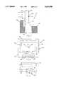
- FIGS. 1 and 2are side and front views, respectively, of a silicon flow sensor in accordance with a first embodiment of this invention
- FIG. 3shows the flow sensor of FIGS. 1 and 2 assembled within a module that is placed in an air duct;
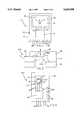
- FIG. 4is a front view of the flow sensor of this invention in combination with a pressure sensor on a single silicon chip, in accordance with a second embodiment of this invention
- FIG. 5is a side views of a silicon flow sensor incorporating motion stops in accordance with a third embodiment of this invention.
- FIG. 6is a front view of the flow sensor of this invention in combination with control and compensation circuitry on a package substrate, in accordance with a fourth embodiment of this invention.
- FIGS. 7 through 9are graphs showing the signal output response of the flow sensor of FIGS. 1 and 2.
- a flow sensor 10 in accordance with a first embodiment of this inventionis shown in cross-section in FIG. 1.
- the sensor 10is generally represented as being formed by a single silicon chip 12 whose outer dimensions are typical for silicon wafer chips, generally on the order of about 4000 micrometers by about 6000 micrometers by about 380 micrometers in thickness.
- the chip 12has a base 14 secured by a housing 16, which can generally be of any suitable construction and material capable of adequately supporting and anchoring the chip 12 within its intended operating environment.
- FIG. 2which is a plan view the chip 12 as seen when isolated from the housing 16, the chip 12 can be seen to define a vane 18 cantilevered from the base 14.
- the vane 18is adapted to be deflected in response to fluid flow that impinges either of its broader surfaces 18a and 18b, such that the sensor 10 is capable of bidirectional operation. As shown, one of the broader surfaces 18a of the vane 18 is contiguous and coplanar with a surface of the base 14, though other configurations are foreseeable.
- the vane 18is preferably micromachined from the chip 12 using any suitably micromachining technique so as to be surrounded by a frame 22, such that a gap 24 having a predeterminable width is present therebetween.
- the vane 18is preferably micromachined such that its thickness in the direction of fluid flow is thinner than that of the base 14.
- a beam 20is defined by a transition region of the chip 12 where the thickness of the chip 12 changes between the vane 18 and the base 12. This transition reduces stress risers in the chip 12, and establishes a region in the beam 20 in which deflection of the vane 18 will be localized, making the beam 20 highly suited as a location for sensing deflection of the vane 18 with a strain sensing element 26, as shown in FIGS. 1 and 2.
- the beam 20is preferably protected with a barrier 16a from being directly impinged by the fluid being sensed by the vane 18, as shown in FIG. 1, so as to avoid erosion of the beam 20 and the strain sensing element 26. While FIG. 2 illustrates a single-beam configuration for the sensor 10, other beam designs could be employed, such as four-beam, two-beam and folded-beam designs.
- FIG. 2illustrates the use of a pair or a set of four piezoresistors formed on the beam 20 as the strain sensing elements 26 for sensing deflection of the vane 18.
- piezoresistive sensing elementsare well suited for use as the strain sensing element for a silicon pressure sensor or motion-sensor.
- piezoresistorsare highly suitable as the strain sensing elements 26 of this invention, in that they can be readily integrated with appropriate adjusting circuitry in a monolithic silicon integrated circuit.
- the piezoresistorsare preferably formed in a doped epitaxial layer formed on the surface of the chip 12, though for high temperature applications the piezoresistors can be formed within deposited films such as polysilicon or a metal. While piezoresistive sensing elements are preferred, other strain sensing elements, such as strain gauges, could be used. Furthermore, it is foreseeable that the deflection of the vane 18 could be sensed using other techniques, such as capacitive sensing.
- Metal bond pads 28are shown as being provided on the base 14 of the chip 12 through which the input power and output signals of the strain sensing elements 26 are transmitted to and from the sensor 10 for signal conditioning and processing.
- the bond pads 28 and runners (not shown) interconnecting the piezoresistors to the bond pads 28should be formed from polysilicon or a noble metal such as gold, platinum or palladium, or should be shielded from the gas or liquid being sensed.
- the housing 16can be designed to protect the bond pads 28 and runners, or the sensor 10 can include a plastic or wax layer that covers the bond pads 28 and runners, as is done with piezoresistive pressure sensors known in the art.
- the degree that the vane 18 will deflect in response to a given rate of fluid flowis influenced by the size of the vane 18.
- the size of the vane 18can be readily tailored during micromachining of the chip 12 to achieve a size suitably adapted for the operating environment of the sensor 10.
- the width of the gap 24 surrounding the vane 18also influences deflection of the vane 18. Greater widths will render the vane 18 less sensitive to flow, while narrower widths will increase sensitivity.
- a vane 18 having planar dimensions of about 1500 by 1500 micrometershas been found practicable when used with a gap 24 of about 25 micrometers.
- the size of the vane 18 and gap 24could vary greatly from these dimensions and still perform well.
- the vane configuration shown in FIG. 2permits various other techniques for modifying its sensitivity.
- the width and thickness of the beam 20 and the number of beams 20can each be readily tailored during processing of the chip 12 to alter the sensitivity of the sensor 10.
- the width of the beam 20must generally be optimized in relation to the size of the vane 18 in order to avoid the vane 18 from becoming unstable within the range of flow rates for the fluid to which it will be exposed.
- the thickness of the epitaxial layer in which the strain sensing elements 26 are formedcan also be tailored to have an intentional affect on sensitivity, with thicker epitaxial layers enabling the use of the sensor 10 in higher flow applications and with more viscous fluids.
- holes 30can be micromachined directly through the vane 18 in order to further alter sensitivity, with fewer and/or smaller holes generally increasing the sensitivity of the sensor 10.
- FIG. 3shows the sensor 10 of this invention disposed within an automobile's air intake duct 32.
- the sensor 10is shown housed within a module 34 that includes a passage into which the vane 18 projects.
- the module 34can be mounted directly to the wall of the duct 32, and can be readily sized to achieve suitably air flow through the passage without unnecessarily restricting air flow through the duct 32.
- the sensor 10could be mounted directly within the duct 32.
- FIG. 4illustrates a sensor 110 having the basic vane configuration shown in FIG. 2 in combination with a pressure sensor diaphragm 36, all of which is formed on the same chip 12.
- the diaphragm 36can be micromachined in the chip 12 in a conventional manner as an absolute or differential sensing element, and with or without a capping chip (not shown) for enclosing a cavity (not shown) that results from the presence of the diaphragm 36 in the chip 12, all of which is conventional in the art of silicon pressure sensors.
- additional metal bond pads 28are required to serve both the strain sensing elements 26 of the flow sensor portion of the sensor 110 and strain or capacitive-sensing elements required for the pressure sensing portion of the sensor 110.
- FIG. 5represents yet another embodiment of this invention, in which wafer-to-wafer bonding is employed to improve the reliability and manufacturability of a silicon flow sensor 210 that incorporates the sensor components shown in FIGS. 1 and 2.
- the sensor 210is shown as including a top capping chip 38 and a bottom capping chip 40 that can be bonded to the chip 12 in any suitable manner.
- the top and bottom capping chips 38 and 40define a passage 42 through which fluid flows to and from the vane 18 of the sensor 210.
- the top and bottom capping chips 38 and 40also provide motion stops 38a and 40a, respectively, which prevent high flow bursts through the passage 42 from damaging the vane 18.
- the passage 42 formed by the capping chips 38 and 40can be tailored to influence the flow to and around the vane 18, and even optimize the flow pattern over the vane 18.
- entrance to the passage 42can be restricted by grooves, slits and/or holes that allow fluid to enter the passage 42, and potentially impinge only a limited portion of the vane 18, while excluding large fluid-borne particles and other undesirable debris.
- FIG. 6illustrates a flow sensor 310 having the basic sensor configuration shown in FIG. 2 in combination with a thick film integrated circuit (IC) 44.
- the sensor 310 and IC 44may be formed on the same chip 12 or, as shown, formed on separate chips housed within a single package 54.
- the IC 44can be a signal processor, temperature compensator, or other control chip such as a microprocessor. If piezoresistors are used as the strain sensing elements 26, they will typically be connected to a suitable signal processing circuitry for measuring the deflection of the vane 18, Furthermore, piezoresistors often require calibration to compensate for the variations that tend to occur during manufacturing between individual strain sensing elements and signal conditioning circuitry during manufacturing.
- Conductors 46are employed to electrically interconnect the sensor 310 with the IC 44.
- the package 54is preferably equipped with electrical programming pads 48 by which the IC can be appropriately programmed, and plug connectors 50 with which the input power can be transmitted to the sensor 310 and the conditioned and processed output signal of the sensor 310 can be transmitted to the appropriate associated control system.
- An opening 52 formed in the package 54allows fluid to flow through the package and over the vane 18.
- the frame 22is also used to attach the sensor 310 over the opening 52 in the package 54.
- An adhesive(not shown) is applied round the opening 52 such that the frame 22 is directly contacted by the adhesive.
- the frame 22serves to mount the sensor chip in the package 54, thereby preventing the adhesive from contacting the vane 18 or beam 20 in order to ensure proper operation of the sensor 310.
- the adhesiveshould be relatively soft (i.e., a low Young's Modulus) and be compatible with the fluid being sensed. A low Young's Modulus is required to prevent packaging stresses from interfering with the piezoresistors on the beam 20.
- FIGS. 7 through 9graphically represent the signal output response of flow sensors configured in accordance with the embodiment of FIG. 6.
- FIG. 7is indicative of the extreme linearity of the sensor for air flow rates above about 150 cubic centimeters per minute (cc 3 /min).
- the particular sensor tested to produce the results shown in FIG. 7had a beam thickness of about twelve micrometers.
- FIG. 8represents similar linearity for a sensor configured in accordance with the embodiment of FIG. 6, but adapted for higher flow conditions. Excellent linearity is apparent from the results represented in FIG. 8 for flow rates of between about 500 and about 1500 cc 3 /min.
- the results depicted in FIGS. 7 and 8also illustrate the desirable bidirectional capability of the sensor design of this invention, in which flow impinging either broad surface 18a or 18b produces a linear output.
- FIG. 9illustrates the extreme linearity of the output signal of a flow sensor configured in accordance with FIG. 6.
- the output signalis shown as being highly linear from a flow rate of about 150 cc 3 /min to about 2500 cc 3 /min.
- the maximum flow rate testedwas limited only be the structural capability of the sensor tested, and not the stability of the vane 18 or the linearity of the sensor output.
- a particularly advantageous aspect of a flow sensor configured in accordance with this inventionis that its output signal resulting from deflection of the vane 18 is extremely linear, which simplifies the need for further signal processing.
- linearityis unaffected by modifications to the sensor in order to alter the sensitivity.
- a sensor configured in accordance with this inventioncan be readily configured to enable its sensitivity to be modified during processing of the chip in which the sensor is formed.
- sensitivitycan be affected by varying the size of the vane 18, the width and thickness of the beam 20, the presence of one or more through-holes in the vane 18, and by forming the sensor to include a frame 22 that surrounds the vane 18 such that a gap having a predeterminable width is present therebetween.
- a sensor configured in accordance with this inventionis very small (the size of a typical IC silicon chip), relatively uncomplicated and rugged, making such sensors particularly well suited for automotive applications.
- the primary and essential component of the sensoris a single silicon chip, which can be readily manufactured using batch processes so as to be cost effective, and then packaged within a housing or sensor module without significantly complicating the manufacture of the sensor.
- the reliance on the vane 18 as the single sensing structure of the sensormakes possible a small sensor, such that the presence of the sensor will have a minimal effect on the flow dynamics of the fluid being sensed.
- the silicon vane of the sensoris adapted to be bidirectionally deflected, which enhances the versatility of the sensor.
- the ability to selectively alter the sensitivity of the sensor during processingalso enhances the versatility of the sensor, enabling a basic sensor design to be adapted to various applications having significantly different flow conditions.
- the sensor design of this inventionprovides a small compact assembly which is amenable to automotive production techniques, yet enables other sensing structures and signal conditioning or temperature compensation circuitry to be incorporated on the same chip that forms the flow sensor.
- sensors configured in accordance with this inventionare characterized by an efficient use of material and packaging. Because of its all-silicon design, sensors of this invention are also useful in applications where the use of prior art flow sensors would be inappropriate.
- the silicon flow sensor of this inventioncan be used to sense the flow of combustible fluids, an application incompatible with prior art hot-wire flow sensors.
Landscapes
- Physics & Mathematics (AREA)
- General Physics & Mathematics (AREA)
- Engineering & Computer Science (AREA)
- Aviation & Aerospace Engineering (AREA)
- Fluid Mechanics (AREA)
- Measuring Volume Flow (AREA)
Abstract
Description
Claims (19)
Priority Applications (1)
| Application Number | Priority Date | Filing Date | Title |
|---|---|---|---|
| US08/512,250US5663508A (en) | 1995-08-07 | 1995-08-07 | Silicon flow sensor |
Applications Claiming Priority (1)
| Application Number | Priority Date | Filing Date | Title |
|---|---|---|---|
| US08/512,250US5663508A (en) | 1995-08-07 | 1995-08-07 | Silicon flow sensor |
Publications (1)
| Publication Number | Publication Date |
|---|---|
| US5663508Atrue US5663508A (en) | 1997-09-02 |
Family
ID=24038309
Family Applications (1)
| Application Number | Title | Priority Date | Filing Date |
|---|---|---|---|
| US08/512,250Expired - LifetimeUS5663508A (en) | 1995-08-07 | 1995-08-07 | Silicon flow sensor |
Country Status (1)
| Country | Link |
|---|---|
| US (1) | US5663508A (en) |
Cited By (43)
| Publication number | Priority date | Publication date | Assignee | Title |
|---|---|---|---|---|
| DE29802971U1 (en) | 1998-02-20 | 1998-09-03 | WWU Wissenschaftliche Werkstatt für Umweltmeßtechnik GmbH, 20459 Hamburg | Micro impeller meter for determining small volume flows |
| US5808200A (en)* | 1997-08-25 | 1998-09-15 | Cosense, Inc. | Ultrasonic sensor with continous and demand self-test for liquid and dry product level measurement |
| US5895866A (en)* | 1996-01-22 | 1999-04-20 | Neukermans; Armand P. | Micromachined silicon micro-flow meter |
| US5959219A (en)* | 1997-07-28 | 1999-09-28 | Saunders; David N. | Capacitive gas flow sensor |
| EP0964228A1 (en)* | 1998-05-19 | 1999-12-15 | Siemens-Elema AB | Fluid flow meter |
| US6212958B1 (en)* | 1998-07-16 | 2001-04-10 | Lincoln Industrial Corporation | Flow sensing assembly and method |
| FR2818738A1 (en)* | 2000-12-23 | 2002-06-28 | Bosch Gmbh Robert | MICROMECHANICAL COMPONENT, IN PARTICULAR MASS FLOW SENSOR |
| US6508112B1 (en) | 2000-01-21 | 2003-01-21 | Dean Verhoeven | Tomographic spray momentum mapping system |
| US20030159697A1 (en)* | 2002-02-22 | 2003-08-28 | Allan Wallace | Flow sensing apparatus |
| US6622569B2 (en)* | 2000-03-10 | 2003-09-23 | Pine Instrument Company | Instrumented mold for use in material testing equipment for measurement of material properties |
| US6631638B2 (en) | 2001-01-30 | 2003-10-14 | Rosemount Aerospace Inc. | Fluid flow sensor |
| US6631648B2 (en)* | 2001-08-28 | 2003-10-14 | Wisconsin Alumni Research Foundation | Microfluidic flow sensing method and apparatus |
| US20030229388A1 (en)* | 2002-06-07 | 2003-12-11 | Hayashi Reid K. | Endovascular graft with pressure, temperature, flow and voltage sensors |
| US20040025598A1 (en)* | 2000-09-21 | 2004-02-12 | Festo Ag & Co. | Integrated fluid sensing device |
| US6794213B1 (en) | 2002-08-29 | 2004-09-21 | The United States Of America As Represented By The Administrator Of The National Aeronautics And Space Administration | Method of assembling a silicon carbide high temperature anemometer |
| US20040199238A1 (en)* | 2002-06-07 | 2004-10-07 | Brown Peter S. | Endovascular graft wih separable sensors |
| US20050107866A1 (en)* | 2002-06-07 | 2005-05-19 | Brown Peter S. | Endovascular graft with pressor and attachment methods |
| US7021151B1 (en)* | 2004-10-29 | 2006-04-04 | National Semiconductor Corporation | MEMS pressure sensing array with leaking sensor |
| US20060200220A1 (en)* | 2002-06-07 | 2006-09-07 | Brown Peter S | Endovascular graft with sensors design and attachment methods |
| US7121146B1 (en) | 2004-10-29 | 2006-10-17 | National Semiconductor Corporation | MEMS pressure sensing device |
| US20070016384A1 (en)* | 2005-04-08 | 2007-01-18 | Edward Niblock Trevor G | Compact pressure-sensing device |
| US7168330B1 (en)* | 2006-06-07 | 2007-01-30 | Northrop Grumman Corporation | Multi-parametric media transducer |
| US20070295104A1 (en)* | 2006-06-12 | 2007-12-27 | Precision Pumping Systems, Inc. | Fluid sensor with mechanical positional feedback |
| US7328609B1 (en) | 2004-10-29 | 2008-02-12 | National Semiconductor Corporation | Wireless pressure sensing Schrader valve |
| WO2008079158A1 (en) | 2006-12-26 | 2008-07-03 | Integrated Sensing Systems, Inc. | Sensing and analysis system, data transmission over network |
| US20080223143A1 (en)* | 2005-09-16 | 2008-09-18 | Stmicroelectronics S.R.L. | Pressure sensor having a high full-scale value with package thereof |
| US20090105557A1 (en)* | 2007-10-17 | 2009-04-23 | Integrated Sensing Systems, Inc. | System having wireless implantable sensor |
| US20090149810A1 (en)* | 2007-12-06 | 2009-06-11 | Lawrence Scott Ring | Implantable Infusion Devices Including Apparatus For Confirming Fluid Flow And Systems, Apparatus And Methods Associated With Same |
| US20090205544A1 (en)* | 2008-02-18 | 2009-08-20 | Alstom Technology Ltd | Coal rope locator |
| US20100186517A1 (en)* | 2009-01-28 | 2010-07-29 | American Power Conversion Corporation | Method and system for detecting air pressure neutrality in air containment zones |
| US7918800B1 (en) | 2004-10-08 | 2011-04-05 | Endovascular Technologies, Inc. | Aneurysm sensing devices and delivery systems |
| US20110079092A1 (en)* | 2009-10-02 | 2011-04-07 | Mansour Adel B | Low-power force sensor |
| CN101271164B (en)* | 2007-03-21 | 2011-07-06 | 中国科学院电子学研究所 | A guided wind direction and wind speed sensor |
| US8407004B2 (en) | 2010-04-29 | 2013-03-26 | Schneider Electric It Corporation | Airflow detector and method of measuring airflow |
| US8534119B2 (en) | 2010-12-30 | 2013-09-17 | Schneider Electric It Corporation | System and method for air containment zone air leakage detection |
| JP2014089183A (en)* | 2012-10-03 | 2014-05-15 | Seiko Instruments Inc | Pressure sensor |
| CN104482964A (en)* | 2014-12-17 | 2015-04-01 | 哈尔滨理工大学 | Integrated high-accuracy boronized semiconductor heating wind speed and direction sensor |
| CN104950133A (en)* | 2015-07-06 | 2015-09-30 | 浙江大学 | Microfluidic flow rate sensor chip, detection system and detection method |
| US20170108361A1 (en)* | 2015-10-18 | 2017-04-20 | Cdi Meters, Inc. | Target Flowmeter |
| WO2019011520A1 (en)* | 2017-07-12 | 2019-01-17 | Grohe Ag | DEVICE WITH SENSORS FOR RECEIVING MEASUREMENT SIZES OF A FLUID, ESPECIALLY FOR ARRANGEMENT IN A FLUID PIPE |
| FR3073285A1 (en)* | 2017-11-06 | 2019-05-10 | Atlantic Climatisation & Ventilation | DEVICE FOR MEASURING AIR FLOW FOR A VENTILATION INSTALLATION |
| US20190250055A1 (en)* | 2018-02-14 | 2019-08-15 | Carefusion 303, Inc. | Integrated sensor to monitor fluid delivery |
| US20190250020A1 (en)* | 2016-07-13 | 2019-08-15 | Coroflo Limited | Sensor-based breastfeeding volume measurement device |
Citations (8)
| Publication number | Priority date | Publication date | Assignee | Title |
|---|---|---|---|---|
| US3298230A (en)* | 1963-10-28 | 1967-01-17 | Stover Emory Frank | Vane type flow meter |
| US3340733A (en)* | 1964-09-28 | 1967-09-12 | Exxon Research Engineering Co | Design for a strain gauge target flow meter |
| US3722264A (en)* | 1971-01-25 | 1973-03-27 | Itt | Transducer and components therefor |
| US4625565A (en)* | 1984-04-09 | 1986-12-02 | Sinko Kogyo Co., Ltd. | Wind velocity sensor |
| US4670092A (en)* | 1986-04-18 | 1987-06-02 | Rockwell International Corporation | Method of fabricating a cantilever beam for a monolithic accelerometer |
| US5131265A (en)* | 1991-02-22 | 1992-07-21 | Motorola, Inc. | Real-time rheology measurement sensor |
| US5279162A (en)* | 1988-09-02 | 1994-01-18 | Honda Giken Kogyo Kabushiki Kaisha | Semiconductor sensor |
| US5319980A (en)* | 1991-06-07 | 1994-06-14 | Maclean-Fogg Company | Board construction for resistive strain gauge pressure sensors |
- 1995
- 1995-08-07USUS08/512,250patent/US5663508A/ennot_activeExpired - Lifetime
Patent Citations (8)
| Publication number | Priority date | Publication date | Assignee | Title |
|---|---|---|---|---|
| US3298230A (en)* | 1963-10-28 | 1967-01-17 | Stover Emory Frank | Vane type flow meter |
| US3340733A (en)* | 1964-09-28 | 1967-09-12 | Exxon Research Engineering Co | Design for a strain gauge target flow meter |
| US3722264A (en)* | 1971-01-25 | 1973-03-27 | Itt | Transducer and components therefor |
| US4625565A (en)* | 1984-04-09 | 1986-12-02 | Sinko Kogyo Co., Ltd. | Wind velocity sensor |
| US4670092A (en)* | 1986-04-18 | 1987-06-02 | Rockwell International Corporation | Method of fabricating a cantilever beam for a monolithic accelerometer |
| US5279162A (en)* | 1988-09-02 | 1994-01-18 | Honda Giken Kogyo Kabushiki Kaisha | Semiconductor sensor |
| US5131265A (en)* | 1991-02-22 | 1992-07-21 | Motorola, Inc. | Real-time rheology measurement sensor |
| US5319980A (en)* | 1991-06-07 | 1994-06-14 | Maclean-Fogg Company | Board construction for resistive strain gauge pressure sensors |
Non-Patent Citations (2)
| Title |
|---|
| Flow Its Measurement and Control in Science and Industry Volume Two 1981 St. Louis William W. Durgin Editor in Chief, Article E 706 entitled Miniature Drag Force Anemometer by L. N. Krause and G. C. Fralick pp. 117 130.* |
| Flow Its Measurement and Control in Science and Industry --Volume Two 1981 St. Louis William W. Durgin Editor-in-Chief, Article E-706 entitled "Miniature Drag-Force Anemometer" by L. N. Krause and G. C. Fralick pp. 117-130. |
Cited By (84)
| Publication number | Priority date | Publication date | Assignee | Title |
|---|---|---|---|---|
| US5895866A (en)* | 1996-01-22 | 1999-04-20 | Neukermans; Armand P. | Micromachined silicon micro-flow meter |
| US5959219A (en)* | 1997-07-28 | 1999-09-28 | Saunders; David N. | Capacitive gas flow sensor |
| US5808200A (en)* | 1997-08-25 | 1998-09-15 | Cosense, Inc. | Ultrasonic sensor with continous and demand self-test for liquid and dry product level measurement |
| DE29802971U1 (en) | 1998-02-20 | 1998-09-03 | WWU Wissenschaftliche Werkstatt für Umweltmeßtechnik GmbH, 20459 Hamburg | Micro impeller meter for determining small volume flows |
| EP0964228A1 (en)* | 1998-05-19 | 1999-12-15 | Siemens-Elema AB | Fluid flow meter |
| US6345540B1 (en)* | 1998-05-19 | 2002-02-12 | Siemens Elema Ab | Fluid flow meter |
| US6212958B1 (en)* | 1998-07-16 | 2001-04-10 | Lincoln Industrial Corporation | Flow sensing assembly and method |
| US6508112B1 (en) | 2000-01-21 | 2003-01-21 | Dean Verhoeven | Tomographic spray momentum mapping system |
| US6622569B2 (en)* | 2000-03-10 | 2003-09-23 | Pine Instrument Company | Instrumented mold for use in material testing equipment for measurement of material properties |
| US6971272B2 (en) | 2000-09-21 | 2005-12-06 | Festo Ag & Co. | Integrated fluid sensing device |
| US20050121080A1 (en)* | 2000-09-21 | 2005-06-09 | Festo Ag & Co | Integrated fluid sensing device |
| US20040025598A1 (en)* | 2000-09-21 | 2004-02-12 | Festo Ag & Co. | Integrated fluid sensing device |
| US20020174724A1 (en)* | 2000-12-23 | 2002-11-28 | Hubert Benzel | Micromechanical component |
| FR2818738A1 (en)* | 2000-12-23 | 2002-06-28 | Bosch Gmbh Robert | MICROMECHANICAL COMPONENT, IN PARTICULAR MASS FLOW SENSOR |
| US6631638B2 (en) | 2001-01-30 | 2003-10-14 | Rosemount Aerospace Inc. | Fluid flow sensor |
| US6631648B2 (en)* | 2001-08-28 | 2003-10-14 | Wisconsin Alumni Research Foundation | Microfluidic flow sensing method and apparatus |
| US20030159697A1 (en)* | 2002-02-22 | 2003-08-28 | Allan Wallace | Flow sensing apparatus |
| US7024945B2 (en)* | 2002-02-22 | 2006-04-11 | Compumedics Limited | Flow sensing apparatus |
| US20030229388A1 (en)* | 2002-06-07 | 2003-12-11 | Hayashi Reid K. | Endovascular graft with pressure, temperature, flow and voltage sensors |
| US20050107866A1 (en)* | 2002-06-07 | 2005-05-19 | Brown Peter S. | Endovascular graft with pressor and attachment methods |
| US20040199238A1 (en)* | 2002-06-07 | 2004-10-07 | Brown Peter S. | Endovascular graft wih separable sensors |
| US7025778B2 (en) | 2002-06-07 | 2006-04-11 | Endovascular Technologies, Inc. | Endovascular graft with pressure, temperature, flow and voltage sensors |
| US20060149347A1 (en)* | 2002-06-07 | 2006-07-06 | Hayashi Reid K | Endovascular graft with pressure, temperature, flow and voltage sensors |
| US20060200220A1 (en)* | 2002-06-07 | 2006-09-07 | Brown Peter S | Endovascular graft with sensors design and attachment methods |
| US7261733B1 (en) | 2002-06-07 | 2007-08-28 | Endovascular Technologies, Inc. | Endovascular graft with sensors design and attachment methods |
| US7488345B2 (en) | 2002-06-07 | 2009-02-10 | Endovascular Technologies, Inc. | Endovascular graft with pressor and attachment methods |
| US7399313B2 (en) | 2002-06-07 | 2008-07-15 | Brown Peter S | Endovascular graft with separable sensors |
| US6794213B1 (en) | 2002-08-29 | 2004-09-21 | The United States Of America As Represented By The Administrator Of The National Aeronautics And Space Administration | Method of assembling a silicon carbide high temperature anemometer |
| US20110213413A1 (en)* | 2004-10-08 | 2011-09-01 | Endovascular Technologies, Inc. | Aneurysm sensing devices and delivery systems |
| US7918800B1 (en) | 2004-10-08 | 2011-04-05 | Endovascular Technologies, Inc. | Aneurysm sensing devices and delivery systems |
| US7121146B1 (en) | 2004-10-29 | 2006-10-17 | National Semiconductor Corporation | MEMS pressure sensing device |
| US7328609B1 (en) | 2004-10-29 | 2008-02-12 | National Semiconductor Corporation | Wireless pressure sensing Schrader valve |
| US7021151B1 (en)* | 2004-10-29 | 2006-04-04 | National Semiconductor Corporation | MEMS pressure sensing array with leaking sensor |
| US7373833B2 (en) | 2004-10-29 | 2008-05-20 | National Semiconductor Corporation | MEMS pressure sensing device |
| US20060278009A1 (en)* | 2004-10-29 | 2006-12-14 | Hopper Peter J | MEMS pressure sensing device |
| US7543502B2 (en)* | 2005-04-08 | 2009-06-09 | Analatom Incorporated | Compact pressure-sensing device |
| US8397579B2 (en) | 2005-04-08 | 2013-03-19 | Analatom Incorporated | Compact pressure-sensing device |
| US20070016384A1 (en)* | 2005-04-08 | 2007-01-18 | Edward Niblock Trevor G | Compact pressure-sensing device |
| US8024977B2 (en)* | 2005-09-16 | 2011-09-27 | Stmicroelectronics S.R.L. | Pressure sensor having a high full-scale value with package thereof |
| US20080223143A1 (en)* | 2005-09-16 | 2008-09-18 | Stmicroelectronics S.R.L. | Pressure sensor having a high full-scale value with package thereof |
| US7168330B1 (en)* | 2006-06-07 | 2007-01-30 | Northrop Grumman Corporation | Multi-parametric media transducer |
| US20070295104A1 (en)* | 2006-06-12 | 2007-12-27 | Precision Pumping Systems, Inc. | Fluid sensor with mechanical positional feedback |
| US7921726B2 (en)* | 2006-06-12 | 2011-04-12 | Precision Pumping Systems, Inc. | Fluid sensor with mechanical positional feedback |
| WO2007146893A3 (en)* | 2006-06-12 | 2008-02-21 | Prec Pumping Systems Inc | Fluid sensor with mechanical positional feedback |
| WO2008079158A1 (en) | 2006-12-26 | 2008-07-03 | Integrated Sensing Systems, Inc. | Sensing and analysis system, data transmission over network |
| CN101271164B (en)* | 2007-03-21 | 2011-07-06 | 中国科学院电子学研究所 | A guided wind direction and wind speed sensor |
| US20090105557A1 (en)* | 2007-10-17 | 2009-04-23 | Integrated Sensing Systems, Inc. | System having wireless implantable sensor |
| US8744544B2 (en) | 2007-10-17 | 2014-06-03 | Integrated Sensing Systems, Inc. | System having wireless implantable sensor |
| US20090149810A1 (en)* | 2007-12-06 | 2009-06-11 | Lawrence Scott Ring | Implantable Infusion Devices Including Apparatus For Confirming Fluid Flow And Systems, Apparatus And Methods Associated With Same |
| US10646646B2 (en) | 2007-12-06 | 2020-05-12 | The Alfred E. Mann Found. For Scientific Research | Implantable infusion devices including apparatus for confirming fluid flow and systems, apparatus and methods associated with same |
| US9327074B2 (en) | 2007-12-06 | 2016-05-03 | Medallion Therapeutics, Inc. | Implantable infusion devices including apparatus for confirming fluid flow and systems, apparatus and methods associated with same |
| US8323268B2 (en) | 2007-12-06 | 2012-12-04 | The Alfred E. Mann Foundation For Scientific Research | Implantable infusion devices including apparatus for confirming fluid flow and systems, apparatus and methods associated with same |
| US20090205544A1 (en)* | 2008-02-18 | 2009-08-20 | Alstom Technology Ltd | Coal rope locator |
| US7921738B2 (en)* | 2008-02-18 | 2011-04-12 | Alstom Technology Ltd | Device for identifying the location of coal ropes |
| US20100186517A1 (en)* | 2009-01-28 | 2010-07-29 | American Power Conversion Corporation | Method and system for detecting air pressure neutrality in air containment zones |
| CN102365529A (en)* | 2009-01-28 | 2012-02-29 | 美国能量变换公司 | Method and system for detecting air pressure neutrality in air containment zones |
| WO2010087917A1 (en)* | 2009-01-28 | 2010-08-05 | American Power Conversion Corporation | Method and system for detecting air pressure neutrality in air containment zones |
| CN102365529B (en)* | 2009-01-28 | 2013-05-08 | 美国能量变换公司 | Method and system for detecting air pressure neutrality in air containment zones |
| US7861596B2 (en) | 2009-01-28 | 2011-01-04 | American Power Conversion Corporation | Method and system for detecting air pressure neutrality in air containment zones |
| AU2009338700B2 (en)* | 2009-01-28 | 2014-04-17 | Schneider Electric It Corporation | Method and system for detecting air pressure neutrality in air containment zones |
| US8534143B2 (en)* | 2009-10-02 | 2013-09-17 | Parker-Hannifin Corporation | Low-power force sensor |
| US20110079092A1 (en)* | 2009-10-02 | 2011-04-07 | Mansour Adel B | Low-power force sensor |
| US8407004B2 (en) | 2010-04-29 | 2013-03-26 | Schneider Electric It Corporation | Airflow detector and method of measuring airflow |
| US8534119B2 (en) | 2010-12-30 | 2013-09-17 | Schneider Electric It Corporation | System and method for air containment zone air leakage detection |
| US9274019B2 (en) | 2010-12-30 | 2016-03-01 | Schneider Electric It Corporation | System and method for air containment zone air leakage detection |
| JP2014089183A (en)* | 2012-10-03 | 2014-05-15 | Seiko Instruments Inc | Pressure sensor |
| CN104482964A (en)* | 2014-12-17 | 2015-04-01 | 哈尔滨理工大学 | Integrated high-accuracy boronized semiconductor heating wind speed and direction sensor |
| CN104482964B (en)* | 2014-12-17 | 2017-02-22 | 哈尔滨理工大学 | Integrated high-accuracy boronized semiconductor heating wind speed and direction sensor |
| CN104950133A (en)* | 2015-07-06 | 2015-09-30 | 浙江大学 | Microfluidic flow rate sensor chip, detection system and detection method |
| CN104950133B (en)* | 2015-07-06 | 2017-12-15 | 浙江大学 | Microfluid flow velocity sensing chip, detecting system and detection method |
| US20170108361A1 (en)* | 2015-10-18 | 2017-04-20 | Cdi Meters, Inc. | Target Flowmeter |
| US10928228B2 (en)* | 2016-07-13 | 2021-02-23 | Coroflo Limited | Sensor-based breastfeeding volume measurement device |
| US20190250020A1 (en)* | 2016-07-13 | 2019-08-15 | Coroflo Limited | Sensor-based breastfeeding volume measurement device |
| US11340098B2 (en) | 2017-07-12 | 2022-05-24 | Grohe Ag | Device having sensors for sensing measurement variables of a fluid, in particular for arranging in a fluid line |
| WO2019011520A1 (en)* | 2017-07-12 | 2019-01-17 | Grohe Ag | DEVICE WITH SENSORS FOR RECEIVING MEASUREMENT SIZES OF A FLUID, ESPECIALLY FOR ARRANGEMENT IN A FLUID PIPE |
| FR3073285A1 (en)* | 2017-11-06 | 2019-05-10 | Atlantic Climatisation & Ventilation | DEVICE FOR MEASURING AIR FLOW FOR A VENTILATION INSTALLATION |
| US10809139B2 (en)* | 2018-02-14 | 2020-10-20 | Carefusion 303, Inc. | Integrated sensor to monitor fluid delivery |
| CN111727066A (en)* | 2018-02-14 | 2020-09-29 | 康尔福盛303公司 | Integrated sensors for monitoring fluid delivery |
| US20200408628A1 (en)* | 2018-02-14 | 2020-12-31 | Carefusion 303, Inc. | Integrated sensor to monitor fluid delivery |
| JP2021512737A (en)* | 2018-02-14 | 2021-05-20 | ケアフュージョン 303、インコーポレイテッド | Integrated sensor for monitoring fluid delivery |
| US20190250055A1 (en)* | 2018-02-14 | 2019-08-15 | Carefusion 303, Inc. | Integrated sensor to monitor fluid delivery |
| US11740148B2 (en)* | 2018-02-14 | 2023-08-29 | Carefusion 303, Inc. | Integrated sensor to monitor fluid delivery |
| CN111727066B (en)* | 2018-02-14 | 2023-09-19 | 康尔福盛303公司 | Integrated sensor for monitoring fluid delivery |
| AU2019222638B2 (en)* | 2018-02-14 | 2024-03-14 | Carefusion 303, Inc. | Integrated sensor to monitor fluid delivery |
Similar Documents
| Publication | Publication Date | Title |
|---|---|---|
| US5663508A (en) | Silicon flow sensor | |
| US6272928B1 (en) | Hermetically sealed absolute and differential pressure transducer | |
| US6229190B1 (en) | Compensated semiconductor pressure sensor | |
| EP2912426B1 (en) | Combined pressure and humidity sensor | |
| US5284057A (en) | Microaccelerometer having low stress bonds and means for preventing excessive Z-axis deflection | |
| US10724909B2 (en) | Microelectromechanical scalable bulk-type piezoresistive force/pressure sensor | |
| US6182509B1 (en) | Accelerometer without proof mass | |
| JP4421511B2 (en) | Semiconductor pressure sensor | |
| US7436037B2 (en) | Moisture resistant pressure sensors | |
| US6813956B2 (en) | Double stop structure for a pressure transducer | |
| US7762139B2 (en) | Pressure transducer apparatus adapted to measure engine pressure parameters | |
| US6293154B1 (en) | Vibration compensated pressure sensing assembly | |
| US8631707B2 (en) | Differential temperature and acceleration compensated pressure transducer | |
| US5537882A (en) | Semiconductor sensor for detecting physical amount without thermal hypsteresis where output wiring is disposed in a stress insensitive direction | |
| JPH09126934A (en) | Pressure detector to detect pressure in combustion chamber of internal combustion engine | |
| JP2503290B2 (en) | Semiconductor pressure / differential pressure measurement diaphragm | |
| JP2804874B2 (en) | Semiconductor acceleration detector | |
| US20020020689A1 (en) | Accelerometer without proof mass | |
| US5932809A (en) | Sensor with silicon strain gage | |
| US7178403B2 (en) | Transducer responsive to pressure, vibration/acceleration and temperature and methods of fabricating the same | |
| US5698785A (en) | Self-compensating accelerometer | |
| US5748567A (en) | Acceleration sensor | |
| US4864724A (en) | Planar mounting of silicon micromachined sensors for pressure and fluid-flow measurement | |
| JPS61144576A (en) | semiconductor acceleration sensor | |
| JP3330831B2 (en) | Strain detection sensor |
Legal Events
| Date | Code | Title | Description |
|---|---|---|---|
| AS | Assignment | Owner name:DELCO ELECTRONICS CORPORATION, INDIANA Free format text:ASSIGNMENT OF ASSIGNORS INTEREST;ASSIGNOR:SPARKS, DOUGLAS RAY;REEL/FRAME:007827/0616 Effective date:19950802 | |
| STCF | Information on status: patent grant | Free format text:PATENTED CASE | |
| FPAY | Fee payment | Year of fee payment:4 | |
| FPAY | Fee payment | Year of fee payment:8 | |
| REMI | Maintenance fee reminder mailed | ||
| AS | Assignment | Owner name:DELPHI TECHNOLOGIES, INC., MICHIGAN Free format text:ASSIGNMENT OF ASSIGNORS INTEREST;ASSIGNOR:DELCO ELECTRONICS CORPORATION;REEL/FRAME:016700/0623 Effective date:20050701 | |
| AS | Assignment | Owner name:JPMORGAN CHASE BANK, N.A., TEXAS Free format text:SECURITY AGREEMENT;ASSIGNOR:DELPHI TECHNOLOGIES, INC.;REEL/FRAME:016237/0402 Effective date:20050614 | |
| AS | Assignment | Owner name:DELPHI TECHNOLOGIES, INC., MICHIGAN Free format text:RELEASE OF SECURITY AGREEMENT;ASSIGNOR:JPMORGAN CHASE BANK, N.A.;REEL/FRAME:020808/0583 Effective date:20080225 | |
| FPAY | Fee payment | Year of fee payment:12 | |
| AS | Assignment | Owner name:GOOGLE INC., CALIFORNIA Free format text:ASSIGNMENT OF ASSIGNORS INTEREST;ASSIGNOR:DELPHI TECHNOLOGIES, INC.;REEL/FRAME:026885/0288 Effective date:20110624 | |
| AS | Assignment | Owner name:GOOGLE LLC, CALIFORNIA Free format text:CHANGE OF NAME;ASSIGNOR:GOOGLE INC.;REEL/FRAME:044144/0001 Effective date:20170929 | |
| AS | Assignment | Owner name:GOOGLE LLC, CALIFORNIA Free format text:CORRECTIVE ASSIGNMENT TO CORRECT THE THE REMOVAL OF THE INCORRECTLY RECORDED APPLICATION NUMBERS 14/149802 AND 15/419313 PREVIOUSLY RECORDED AT REEL: 44144 FRAME: 1. ASSIGNOR(S) HEREBY CONFIRMS THE CHANGE OF NAME;ASSIGNOR:GOOGLE INC.;REEL/FRAME:068092/0502 Effective date:20170929 |