US5663506A - Capacitive temperature and pressure transducer - Google Patents
Capacitive temperature and pressure transducerDownload PDFInfo
- Publication number
- US5663506A US5663506AUS08/517,529US51752995AUS5663506AUS 5663506 AUS5663506 AUS 5663506AUS 51752995 AUS51752995 AUS 51752995AUS 5663506 AUS5663506 AUS 5663506A
- Authority
- US
- United States
- Prior art keywords
- pressure
- temperature
- sensor signal
- capacitor
- sensing
- Prior art date
- Legal status (The legal status is an assumption and is not a legal conclusion. Google has not performed a legal analysis and makes no representation as to the accuracy of the status listed.)
- Expired - Fee Related
Links
Images


Classifications
- G—PHYSICS
- G01—MEASURING; TESTING
- G01L—MEASURING FORCE, STRESS, TORQUE, WORK, MECHANICAL POWER, MECHANICAL EFFICIENCY, OR FLUID PRESSURE
- G01L9/00—Measuring steady of quasi-steady pressure of fluid or fluent solid material by electric or magnetic pressure-sensitive elements; Transmitting or indicating the displacement of mechanical pressure-sensitive elements, used to measure the steady or quasi-steady pressure of a fluid or fluent solid material, by electric or magnetic means
- G01L9/12—Measuring steady of quasi-steady pressure of fluid or fluent solid material by electric or magnetic pressure-sensitive elements; Transmitting or indicating the displacement of mechanical pressure-sensitive elements, used to measure the steady or quasi-steady pressure of a fluid or fluent solid material, by electric or magnetic means by making use of variations in capacitance, i.e. electric circuits therefor
- G01L9/125—Measuring steady of quasi-steady pressure of fluid or fluent solid material by electric or magnetic pressure-sensitive elements; Transmitting or indicating the displacement of mechanical pressure-sensitive elements, used to measure the steady or quasi-steady pressure of a fluid or fluent solid material, by electric or magnetic means by making use of variations in capacitance, i.e. electric circuits therefor with temperature compensating means
- G—PHYSICS
- G01—MEASURING; TESTING
- G01L—MEASURING FORCE, STRESS, TORQUE, WORK, MECHANICAL POWER, MECHANICAL EFFICIENCY, OR FLUID PRESSURE
- G01L15/00—Devices or apparatus for measuring two or more fluid pressure values simultaneously
- G—PHYSICS
- G01—MEASURING; TESTING
- G01L—MEASURING FORCE, STRESS, TORQUE, WORK, MECHANICAL POWER, MECHANICAL EFFICIENCY, OR FLUID PRESSURE
- G01L19/00—Details of, or accessories for, apparatus for measuring steady or quasi-steady pressure of a fluent medium insofar as such details or accessories are not special to particular types of pressure gauges
- G01L19/02—Arrangements for preventing, or for compensating for, effects of inclination or acceleration of the measuring device; Zero-setting means
- G—PHYSICS
- G01—MEASURING; TESTING
- G01L—MEASURING FORCE, STRESS, TORQUE, WORK, MECHANICAL POWER, MECHANICAL EFFICIENCY, OR FLUID PRESSURE
- G01L9/00—Measuring steady of quasi-steady pressure of fluid or fluent solid material by electric or magnetic pressure-sensitive elements; Transmitting or indicating the displacement of mechanical pressure-sensitive elements, used to measure the steady or quasi-steady pressure of a fluid or fluent solid material, by electric or magnetic means
- G01L9/0041—Transmitting or indicating the displacement of flexible diaphragms
- G01L9/0072—Transmitting or indicating the displacement of flexible diaphragms using variations in capacitance
- G01L9/0075—Transmitting or indicating the displacement of flexible diaphragms using variations in capacitance using a ceramic diaphragm, e.g. alumina, fused quartz, glass
Definitions
- the present inventionrelates to a pressure transducer system for accurately measuring such parameters as pressure and temperature and for calculating, among other data, mass flow.
- the systemincludes a monolithic multi-variable capacitive sensor and its associated circuitry.
- Pressure transducers used to measure the pressure of a process fluid (gas or liquid) flowing through a pipeare known in the art. Pressure transducers are used in highly sensitive environments including refineries, the aerospace industry and power plants. The accurate detection of flow conditions is critical in ensuring the operation and safety of the industries in which pressure transducers are used.
- Parallel plate capacitorsare known in the art wherein one plate is formed of a semiconductor material and the second plate is formed of a metal deposited on a dielectric.
- a second or spacing dielectrice.g., air or silicon oil fills the space between the two capacitor plates.
- transducersUnder normal operations, transducers are subject to physical forces (including vibrations, compression and stress), pressure irregularities and temperature fluctuations which can decrease the accuracy of the measurements. Variations in temperature are extremely common and are particularly troublesome. Temperature changes cause the separation between the capacitor plates to vary due to thermal expansion or contraction of the semiconductor and the metalized dielectric. Temperature also affects the dielectric constant of the spacing dielectric (i.e., the silicon oil). The surface area of the plates also vary with the change in temperatures. The separation distance between the plates, the change in dielectric constant of the spacing dielectric and the variation in plate surface area each effect the capacitance of the sensor and ultimately decrease the accuracy of any pressure readings.
- Prior art methods of compensating for temperatureutilize a separate sensor (e.g., a thermistor which comprises two dissimilar metal bonded together--each metal having different coefficients of expansion) to provide temperature data.
- a microprocessor circuitthen corrects for temperature variations through a series of calculations.
- the various components of the pressure transducersare "matched" in an attempt to make all components expand and contract the exact amounts with the fluctuations in temperature, thereby eliminating temperature as a variable.
- Traditional pressure sensorsare designed to measure either a differential or an absolute pressure. They are usually optimized to accurately measure only a relatively small range of pressures. For instance, a sensor that is designed to accurately measure an absolute pressure that varies from 0 to 50 psi gage, will be unable to measure any pressures over 50 psi. On the other hand, a sensor that is designed to measure pressure in the range of 0 to 5000 psi gage cannot accurately measure a pressure that only varies from 0 to 50 psi gage. If an accurate measurement of this lower pressure range is desired, a separate sensor will be required. Moreover, if measurements of differential pressure or gage pressure are also required, additional sensors would be needed.
- the present inventioncomprises means for detecting temperature variations and providing a temperature sensor signal representative of the temperature variation; means for sensing an absolute pressure and for providing an absolute sensor signal representative of the absolute pressure; and means for sensing a differential pressure and for providing a differential sensor signal representative of the differential pressure.
- the pressure sensorscan be capacitive sensors that are commonly known.
- the temperature detecting meansis a parallel plate, semiconductor capacitor. More particularly, the capacitor that detects temperature is formed on a single, monolithic structure with the pressure sensors.
- the sensor signals for the pressuresare individually compared to the temperature sensor signal to determine a ratio. Since the capacitors that sensed the pressure are also affected by temperature variations, each ratio reduces any inaccuracies due to temperature variations. In addition, the monolithic structure eliminates any temperature variation due to temperature gradient which is commonly present when sensors are separated by physical distances.
- the analog signals generated by the sensorsare converted into digital signals, thereby allowing the use of digital circuitry.
- the digital circuitycan select and store the appropriate sensor signals, compare them at a later time, and have them available for further calculations (e.g., to determine mass flow).
- the monolithic sensor structureis comprised of layers of glass and silicon bonded together. At least one silicon layer is used as a common plate that is shared by all of the capacitors used to detect temperature and pressure.
- the capacitors which detect pressureare variable capacitors and are designed by thinning certain regions of a silicon layer to form pressure-sensitive diaphragms.
- the diaphragmsare preferably made out of the silicon layer that forms the common plate for all capacitors.
- a diaphragm and an oppositely facing metalized section on the glass layerform the necessary capacitor plates.
- Apertures and/or channels produced in the glass and silicon layersare used to expose the diaphragms to the desired pressures in order to be detected.
- the capacitance between the plateschange.
- Each capacitorcan be designed to detect a specific pressure and/or to measure a specific range of pressures.
- the capacitor used to detect temperaturehas one plate formed on a metalized portion of the glass layer and the second plate formed from the same silicon layer which is used to form the diaphragms for the variable capacitors that detect pressure.
- the top surface of the common silicon layerprovides the electrically conductive surface to form one of the required two capacitor plates. Since, the temperature sensing capacitor does not use a diaphragm. Therefore, the temperature sensing capacitor is unaffected by pressure changes. However, as the temperature fluctuates, thermal compression and expansion affects the silicon layer and the metalized layer that form the parallel plates of the temperature sensing capacitor. Thermal variations also change the dielectric constant of the silicon oil.
- the preferred embodimentutilizes three capacitors (one for temperature and two for pressure), the number of capacitors, the parameters they measure and the pressure range to which they are sensitive can easily be designed into a particular monolithic structure.
- the use of a three capacitor monolithic structureprovides the necessary information for accurately measuring mass flow.
- FIG. 1is a perspective view of the preferred header assembly utilized in connection with the subject temperature and pressure transducer.
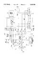
- FIG. 2is a schematic block diagram of the preferred embodiment of the temperature pressure transducer in accordance with the instant invention.
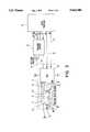
- FIG. 3is an enlarged cross-sectional view of the preferred embodiment of the monolithic pressure sensor used in the subject temperature and pressure transducer system.
- FIG. 4is a schematic circuit diagram of the Enhanced Mode Oscillating circuit.
- the sensing deviceis preferably a monolithic sensor structure 12 having a plurality of sensors (both temperature and pressure).
- the monolithic sensor 12resembles a semiconductor chip and is manufactured in a similar manner as that of a semiconductor chip, however it is a passive device.
- the monolithic sensor structure 12is mounted to a header plate 98 of a header 99 for connection to a manifold (not shown) via a first pressure tube 91 and a second pressure tube 92.
- the manifoldis connected in the usual manner to the device (e.g., gas pipe, pitot tube, storage tank, etc.) in which the fluid to be measured (i.e., the process fluid) is present.
- the devicee.g., gas pipe, pitot tube, storage tank, etc.
- the process fluidis natural gas flowing through a pipe
- the first pressuremay be the upstream pressure of the natural gas and the second pressure may be the downstream pressure of the natural gas after it passes an orifice.
- the manifoldseparates the sensitive components of the monolithic sensor structure 12 from the possible corrosive effects of the process fluid.
- a detection circuit 20sends an electrical signal to a selected sensor on the monolithic sensor structure 12 for reading the desired sensor value.
- the detection circuit which is connected to the sensorsis a custom integrated circuit (IC) chip and is referred to as an Enhanced Mode Oscillating (EMO) circuit 20.
- EMOEnhanced Mode Oscillating
- the circuitdetects the capacitance which vanes directly with any variations in pressure (i.e., the capacitance is directly proportional to the pressure). In the case of a temperature sensing capacitor, its capacitance varies only with changes in temperature.
- the enhanced mode oscillating circuit 20is preferably mounted proximate the monolithic sensor 12. This reduces the physical size of the header 99, limits undesirable capacitor fluctuations (e.g., parasitic capacitances due to lead lengths), and minimizes any effects due to temperature gradients.
- the header 99pressure media isolates the circuit 20 and the sensor 12 from the process fluid. This is done by sealing the header and filling the header 99 with silicon oil. The header also electrically isolates the EMO circuit 20 and the pressure sensors of the monolithic sensor structure 12.
- the isolation provided by header 99is represented by the dashed lines around the monolithic sensor 12 and the EMO circuit 20.
- the monolithic structure 12includes three capacitors C R , C A , and C S .
- the monolithic sensor 12permits the use of a common capacitor plate 89 for all of the capacitors.
- the proximity of all sensors to each othermeans that any temperature variations equally effect all sensors. (Note that this is especially true when compared to the use of separate sensors in which the construction materials may be different and in which the sensors are physically separated which may produce a temperature gradient across the several sensors.)
- Another advantage of using a monolithic structureis the reduction of manufacturing costs as compared to using three separate sensors.
- the first sensorincludes capacitor C R the capacitance of which varies with respect to temperature only.
- the signal initiated by C Ris the temperature sensor signal.
- the second and third sensorsinclude capacitors C A and C S , respectively, which are variable capacitors, the capacitance of which vary primarily with changes in pressure but are also affected by temperature.
- the upper capacitor plate 67 of capacitor C Ris connected to the EMO circuit 20 via lead wire 15.
- the upper plates 65 and 63 of capacitors C A and C Srespectively, are individually connected to the EMO circuit 20 via wires 17 and 19, respectively.
- the common capacitor plate 89is connected to the EMO circuit 20 via lead 90.
- the EMO circuit 20can be interfaced directly to any microprocessor controller (e.g., Motorola 68HC11) that has at least two digital outputs and a serial input.
- the EMO circuit 20is electrically connected to a frequency counter 22 via wire 29 (FO) and microprocessor 24 via wires 31 and 33 (MR and MT, respectively) as shown in FIG. 2.
- the microprocessor 24can select which capacitor is being measured through the EMO circuit 20.
- the temperature or pressureis measured by detecting the capacitance of the desired capacitor C R , C A or C S .
- the EMO circuit 20converts the signal from each capacitor into a digital signal FO (preferably a square wave).
- the period T O of the digital signalis directly proportional to the capacitance of the sensor. Since the capacitance is directly proportional to the detected variable (temperature or pressure), the period of the digital signal output from the EMO circuit 20 is directly proportional to the detected temperature or pressure. (Since frequency is inversely proportional to the period, the frequency of output signal FO is inversely proportional to the capacitance of the selected sensor and, therefore, the frequency is inversely proportional to the respective detected variable).
- the frequency (or period) of the output signal FO for each operating mode of the EMO circuit 20is measured by a frequency counter 22 and converted to a number. This number is transmitted to the processor 24 in serial form via data out line D O .
- the data in line D Ican be used to read in data to set up the frequency counter 22 in its preferred mode of operation.
- the Data Ready line (Dta Rdy)indicates to the processor that the information has been received by the frequency counter.
- the serial clock line SCKprovides the timing for the transfer of information between the frequency counter 22 and the microprocessor 24.
- the monolithic sensor 12comprises alternating layers of a semiconductor substrate (preferably silicon) and a first dielectric (preferably glass) which are attached to each other by anodic bonding.
- a first silicon layer 50is directly bonded the header plate 98 (see FIG. 1).
- a first glass layer 56is positioned over the first silicon layer 50.
- Apertures 52, 58 of the first silicon layer and first glass layer, respectively,provide a means of entry for a second pressure via second tube 92 of the header 99.
- An epoxy ring 51isolates the aperture 52 from outside influences and bonds the silicon layer 50 to the header plate.
- the plurality of capacitorsare formed on a second semiconductor layer 60.
- the second semiconductor layer 60serves as the common plate 89 for all capacitors of the monolithic sensor 12.
- the first capacitor C Rhas a fixed capacitance--with respect to pressure--and is used to measure the reference condition or temperature.
- the second capacitor C Ais a variable capacitor used to measure the absolute pressure (i.e., the first pressure).
- the third capacitor C Sis also a variable capacitor which is used to measure the differential pressure (i.e., the difference in pressure between the first and second pressures). All capacitors are sensitive to temperature variations.
- the monolithic pressure sensor 12uses multiple diaphragms to form a plurality of custom variable capacitors that measure different types of pressure over a pre-designed range.
- the pressure measuring diaphragmsare formed by thinning certain regions of one or more of the silicon layers. The width, thickness and length of the diaphragms can be precisely machined to control pressure range, sensitivity, etc.
- the diaphragmsform the bottom capacitor plate 89 of the variable capacitors.
- the various apertures in the glass and silicon layersare used to expose the diaphragms to the desired pressures.
- the diaphragmsare cut into the second silicon layer 60. All of the diaphragms of the monolithic structure 12 are electrically connected since they are made of a single piece of silicon 60.
- the second silicon layer 60forms the common capacitor plate 89 of variable capacitors C A and C S which are sensitive to pressure variations.
- the second glass layer 66is bonded to the second silicon layer 60.
- Second glass layer 66includes a plurality of through holes or apertures for sensing the temperature and a first pressure delivered from the measured device by first tube 91 of header 99 (see FIG. 1).
- aperture 72is associated with C S
- aperture 74is associated with C A
- aperture 76is associated with C R .
- top or second capacitor plates 63 and 65 of capacitors C S and C Aare formed by plating metal to the underside of second glass layer 66. Similarly, metal is plated to the bottom side of second glass layer 66, proximate absolute sensing diaphragm 94, to form the top capacitor plate 65 of capacitor C A . Finally, metal is plated to the bottom side of glass layer 66, opposite differential sensing diaphragm 80, to form top plate 63 of capacitor C S .
- Aperture 74is metalized to connect top plate 65 to terminal 75 on the top side of second glass layer 66.
- Terminal 73 formed on the top side of glass layer 66is electrically connected to the top plate 63 by metalizing aperture 72.
- Terminals 75 and 73provide convenient electrical contact points for connecting wires 17 and 19, respectively, to the EMO circuit 20.
- Differential pressure sensing diaphragm 80is used to detect the differential pressure between the first pressure which enters through aperture 72 via first tube 91, and the second pressure which enters through apertures 52 and 62 via second tube 92. Differential pressure sensing diaphragm 80 deflects as it is subject to the two pressures. The deflection of diaphragm 80 changes the capacitance of C S in direct proportion to the pressure differential since diaphragm 80 forms the bottom capacitor plate of C S . EMO circuit 20 detects the change in capacitance across top capacitor plate 63 and diaphragm 80 of capacitor C S .
- An absolute pressure sensing diaphragm 94is formed above vacuum sealed cavities 26. Absolute pressure sensing diaphragm 94 forms the bottom or common capacitor plate of capacitor C A . As the pressure entering through aperture 74 via first tube 91 fluctuates, the absolute pressure sensing diaphragm 94 is deflected thereby changing the capacitance C A . The EMO circuit detects the change in capacitance across top capacitor plate 65 and diaphragm 94.
- the top or second plate 67 of capacitor C Ris preferably a metal plated to the bottom side of the second glass layer 66.
- the metalis also circumferentially plated up through aperture 76 to the top side of glass layer 66 forming a terminal 77.
- This terminal 77provides a convenient contact point for connecting wire 15 to the EMO circuit 20.
- Temperature sensing capacitor C Ris not affected by pressure since the bottom or common capacitor plate directly underneath plate 67 is a solid portion of second silicon layer 60. That is, capacitor C R does not utilize a diaphragm and the first pressure which enters through aperture 76 cannot deflect the solid portion of the silicon layer 60. Accordingly, the capacitance of C R is constant regardless of the pressure which enters via first tube 91.
- Annular terminal 88is electrically connected to the common capacitor plate 89 formed by the second silicon layer 60 by metalizing aperture 59.
- a common conductor wire 90is connected to terminal 88 providing the electrical contact between the common plate of each capacitor to the EMO circuit 20.
- wires 15, 17 and 19electrically connect the second capacitor plates 67, 65, 63 of capacitors C R , C A and C S , respectively, to the EMO circuit 20 via terminals 77, 75 and 73.
- the first and second pressures which enter the header 99 via first and second tubes 91 and 92depend on the device to be measured or the data to be collected. For example, when measuring the flow rate of the process fluid through an orifice, the first pressure is the "upstream” pressure of the process fluid and the second pressure is the "downstream” pressure. Similarly, if used to check the presence of a contaminant in a storage tank, the first pressure may be the pressure at the bottom of the tank and the second pressure may be the pressure at the top of the tank.
- the differential pressureis measured by measuring the capacitance of capacitor C S between terminal 73 and common terminal 89 (i.e., across top capacitor plate 63 and bottom common capacitor plate 89).
- the common terminal 89is connected to the EMO circuit 20 via wire 90 and terminal 73 is connected to the EMO circuit via wire 19.
- the difference in pressures between the first pressure entering through aperture 72 and the second pressure entering through apertures 52 and 62causes the differential pressure sensing diaphragm 80 to deflect. In this case, the higher pressure on the top of the diaphragm deflects it downward thus causing a decrease in the capacitance of capacitor C S .
- the first pressuredeflects absolute pressure sensing diaphragm 94 of C A . Since diaphragm 94 sits directly above one or more vacuum sealed compartments 26, the deflection of diaphragm 94 is directly proportional to the absolute pressure of the first pressure. That is, the actual value of the first pressure can be measured.
- FIG. 4A schematic block diagram of the Enhanced Mode Oscillator circuit 20 is shown in FIG. 4.
- the function of the Enhanced Mode Oscillator (EMO) circuit 20is to output an oscillation frequency signal FO that is proportional to the pressure or temperature detected by a capacitor.
- the three capacitorsare sequentially activated in a predetermined order under control of the microprocessor 24.
- Two digital inputs M R and M Tcontrol mode switching which ultimately control a square wave frequency output FO.
- the three capacitors, C R , C A and C Sare connected to three outputs and to one feedback input of the EMO circuit 20.
- the microprocessorvia line M R , resets the EMO circuit 20. This directs the EMO circuit to measure the capacitance of C R .
- the microprocessor 24sends the toggle signal M T to direct the EMO circuit to detect the capacitance of C A .
- the microprocessor 24After the microprocessor 24 has stored the value of C A , it signals the EMO circuit 20, via the M T line, to read the capacitance of C S .
- the microprocessor 24again sends a signal on line M R to reset the EMO circuit 20 and start the cycle over.
- the microprocessor 24typically directs the EMO circuit to take ten readings per second.
- the master latch 102in conjunction with op amps 104 and 108 and current sources 110 and 112, generates a triangle wave.
- the period T of the triangle waveis directly proportional to the measured capacitance of the selected capacitor.
- the slave latch 114generates a square wave which has the same period as the triangle wave.
- Two current sources 110 and 112are switched into an input of op-amp integrator 13 and three capacitors C R , C S and C A are switched to the output of integrator 13.
- the integrator 13 outputis coupled to three comparators 104, 106 and 108. Two of the comparators 104 and 108 trigger the Unscaled Frequency MASTER Latch 102.
- the feedback of UF MASTER Latch 102controls switch 113 which directs the proper current source (110 or 112) connection, causing the integrator 13 output to swing between 0.4 V and 2.4 V.
- the triangle output of the integrator 13causes the >1.4 V comparator 106 to produce a square wave output.
- the square waveclocks the FO SLAVE LATCH 114 on its rising and falling edges.
- the FO Slave Latch output pulsesare "anded" with the enable signal in AND gate 118 to produce the FO output.
- the Mode State Machine 100has three possible states: Ref, Sen, and Abs. When the MR is triggered the state sequence will be Ref, Abs, Sen.
- the mode state machine 100controls switching of the capacitors C R , C A and C S and generates the DIVIDE output. The are divided by two in order to equalize the period of FO as much as possible. Typically, when the data is read out it is scaled by 2 in order to make it consistent with the other T's.
- the RESET output of the Mode State Machine 100sets the UF MASTER Latch 102 and FO SLAVE Latch 114 and rests the ENABLE OUTPUT Latch 116 (disabling the output for one cycle). It also discharges the capacitors C R , C A and C S and holds the integrator 13 output zeroed when the MR or MT lines are held low. If the reset lasts longer than 30 ⁇ sec the one shot 119 times out and the Enable output Latch 116 is enabled and FO will fall synchronously with the rise of MT or MR. Both the MR and MT pulses must be greater than 30 ⁇ sec for synchronous operation to occur.
- the DIVIDE outputcauses the ENABLE OUTPUT latch to toggle and disable every other pulse. This provides a synchronous start will eliminate the uncertainty for the start measurement so the error will be reduced from 2 counts to 1 count. Note that this applies to the system clock not the FO pulses which are always synchronized with the gate time.
- the EMO circuit 20is also effected by temperature (especially the current sources). Therefore, the oscillating frequency of FO is dependent not only on the selected capacitor but also on the current supplied by the EMO circuit. However, by placing the EMO proximate the monolithic sensor 12 (instead of outside of the header 99), inaccuracies due to temperature gradients are further minimized.
- the microprocessor controller 24would send an MR pulse to the EMO circuit 20 which would set its state to connect the capacitor C R to the oscillator in the EMO circuit 20 and thus its period F O would be proportional to C R .
- the frequency counter 22will then count the 10 MHz pulses from the reference oscillator in D pulses of F O .
- the microprocessor controller 24then sends an MT pulse which advances the EMO circuit to its next state--in this case to C A .
- the EMO circuitdetermines the frequency due to C A .
- the next MT pulsecauses the EMO circuit 20 to respond to C S .
- the microprocessor controller 24stores three numbers as described above representative of the capacitance value of C R , C A and C S . These numbers are also sensitive to temperature and it is desired that this influence be minimized; therefore the microprocessor controller 24 calculates the signal representative of differential pressure by determining the ratio C R /C S . In a like manner, the absolute pressure, substantially uninfluenced by the temperature, is calculated by determining the ratio C R /C A .
- T Ris the period of output signal FO when the EMO is connected to capacitor C R .
- T A and T Sare the periods of output signal FO when the EMO is connected to capacitors C A and C S , respectively. Since the temperature variations effected C R , C A and C S substantially equally (because of the monolithic structure), the ratios R Abs and R Diff are independent of temperature.
- the temperature t of the process fluidis obtained by calibrating the microprocessor 24 to capacitor C R at a predetermined temperature t 1 .
- the ratios R t , R Abs and R Diffcan be used to calculate other parameters, for example mass flow rate. This calculation is described in American Gas Association Report No. 3, Orifice Metering of Natural Gas, August 1992 (AGA Catalog No. XQ9210).
- a primary advantage of this inventionis that pressures can be accurately measured despite temperature variations.
- accurate measurement of multiple types of pressure over large ranges of pressureswithout the expense of utilizing multiple pressure sensors is obtainable.
- a financial savingsis realized since all the diaphragms and channels are manufactured on the layers of the sensor at the same time; therefore, the monolithic sensor is no more expensive to produce than traditional single diaphragm sensors.
Landscapes
- Physics & Mathematics (AREA)
- General Physics & Mathematics (AREA)
- Chemical & Material Sciences (AREA)
- Engineering & Computer Science (AREA)
- Ceramic Engineering (AREA)
- Measuring Fluid Pressure (AREA)
Abstract
Description
Claims (18)
Priority Applications (3)
| Application Number | Priority Date | Filing Date | Title |
|---|---|---|---|
| US08/517,529US5663506A (en) | 1995-08-21 | 1995-08-21 | Capacitive temperature and pressure transducer |
| EP96305706AEP0759546A3 (en) | 1995-08-21 | 1996-08-01 | Pressure transducer |
| CA002183896ACA2183896A1 (en) | 1995-08-21 | 1996-08-21 | Capacitive temperature and pressure transducer |
Applications Claiming Priority (1)
| Application Number | Priority Date | Filing Date | Title |
|---|---|---|---|
| US08/517,529US5663506A (en) | 1995-08-21 | 1995-08-21 | Capacitive temperature and pressure transducer |
Publications (1)
| Publication Number | Publication Date |
|---|---|
| US5663506Atrue US5663506A (en) | 1997-09-02 |
Family
ID=24060176
Family Applications (1)
| Application Number | Title | Priority Date | Filing Date |
|---|---|---|---|
| US08/517,529Expired - Fee RelatedUS5663506A (en) | 1995-08-21 | 1995-08-21 | Capacitive temperature and pressure transducer |
Country Status (3)
| Country | Link |
|---|---|
| US (1) | US5663506A (en) |
| EP (1) | EP0759546A3 (en) |
| CA (1) | CA2183896A1 (en) |
Cited By (20)
| Publication number | Priority date | Publication date | Assignee | Title |
|---|---|---|---|---|
| US5790016A (en)* | 1997-01-15 | 1998-08-04 | Algonquin Scientific, Llc | Tire pressure sensing system |
| WO2000043745A1 (en)* | 1999-01-22 | 2000-07-27 | Setra Systems, Inc. | Transducer having temperature compensation |
| US6124787A (en)* | 1997-01-15 | 2000-09-26 | Algonquin Scientific, Llc | Tire pressure sensing system |
| US6335690B1 (en) | 1997-01-15 | 2002-01-01 | Algonquin Scientific, Llc | Fluid sensing system |
| US6362732B1 (en) | 1997-01-15 | 2002-03-26 | Algonquin Scientific Llc | Tire pressure sensing system |
| US6756892B2 (en) | 1997-01-15 | 2004-06-29 | Algonquin Scientific, Llc | Tire pressure sensing system |
| US20070141808A1 (en)* | 2004-09-20 | 2007-06-21 | General Electric Company | Microelectromechanical system pressure sensor and method for making and using |
| US20070237204A1 (en)* | 2004-09-03 | 2007-10-11 | Samsung Electronics Co., Ltd. | Capacitive type temperature sensor |
| US20090178491A1 (en)* | 2008-01-16 | 2009-07-16 | Honeywell International Inc. | Differential pressure assemblies and methods of using same |
| US20110036174A1 (en)* | 2009-08-12 | 2011-02-17 | Hooper Stephen R | Molded Differential PRT Pressure Sensor |
| US20130230813A1 (en)* | 2012-03-05 | 2013-09-05 | Hamilton Sundstrand Corporation | Sensor and sense line heating device |
| US20130269412A1 (en)* | 2010-12-08 | 2013-10-17 | Ifm Electronic Gmbh | Method for self-monitoring a ceramic pressure measuring cell of a capacitive pressure sensor and evaluation circuit for carrying out said method |
| US20130298699A1 (en)* | 2012-04-20 | 2013-11-14 | Rosemount Aerospace Inc. | Separation mode capacitors for sensors |
| WO2014133788A1 (en)* | 2013-02-28 | 2014-09-04 | Mks Instruments, Inc. | Pressure sensor with real time health monitoring and compensation |
| US20140260647A1 (en)* | 2013-03-13 | 2014-09-18 | Invensense, Inc. | Pressure sensor stabilization |
| US9188469B2 (en) | 2009-10-21 | 2015-11-17 | Koninklijke Philips N.V. | Sensor system for measuring a velocity of a fluid including a heating element a resonant circuit and a transducer |
| US20160084722A1 (en)* | 2014-09-24 | 2016-03-24 | Freescale Semiconductor Inc. | Differential Pressure Sensor Assembly |
| GB2533084A (en)* | 2014-12-02 | 2016-06-15 | Melexis Tech N V | Relative and absolute pressure sensor combined on chip |
| CN107872761A (en)* | 2016-09-23 | 2018-04-03 | 苹果公司 | For the pressure gradient microphone for the acoustic feature for measuring loudspeaker |
| CN112197891A (en)* | 2020-09-30 | 2021-01-08 | 厦门天马微电子有限公司 | Sensor, temperature and pressure detection method and sensing device |
Families Citing this family (3)
| Publication number | Priority date | Publication date | Assignee | Title |
|---|---|---|---|---|
| JP2000121473A (en)* | 1998-10-14 | 2000-04-28 | Fuji Electric Co Ltd | Capacitance type absolute pressure detector |
| US6909975B2 (en)* | 2003-11-24 | 2005-06-21 | Mks Instruments, Inc. | Integrated absolute and differential pressure transducer |
| US7633420B2 (en)* | 2008-05-07 | 2009-12-15 | Honeywell International Inc. | Pressure sensor with improved rate-of-change compatible data output |
Citations (29)
| Publication number | Priority date | Publication date | Assignee | Title |
|---|---|---|---|---|
| US2937369A (en)* | 1955-12-29 | 1960-05-17 | Honeywell Regulator Co | Electrical signal measuring apparatus |
| US3631342A (en)* | 1970-01-26 | 1971-12-28 | Vidar Corp | Digital voltmeter apparatus employing a bipolar amplifier having a unidirectional output and a voltage controlled oscillator |
| US3716782A (en)* | 1971-06-03 | 1973-02-13 | J Henry | Capacitance gage for measuring small distances |
| US3753373A (en)* | 1965-10-22 | 1973-08-21 | Bissett Berman Corp | Transducer system |
| US4187460A (en)* | 1977-09-23 | 1980-02-05 | Testut Aequitas | Capacitance measuring by comparison to reference capacitance |
| US4193063A (en)* | 1978-05-15 | 1980-03-11 | Leeds & Northrup Company | Differential capacitance measuring circuit |
| US4257274A (en)* | 1978-07-21 | 1981-03-24 | Hitachi, Ltd. | Capacitive pressure sensor |
| US4295090A (en)* | 1977-10-14 | 1981-10-13 | Vaisala Oy | Electronic selector switch particularly for use in radioscondes |
| US4295091A (en)* | 1978-10-12 | 1981-10-13 | Vaisala Oy | Circuit for measuring low capacitances |
| US4420790A (en)* | 1982-04-02 | 1983-12-13 | Honeywell Inc. | High sensitivity variable capacitance transducer |
| JPS5930035A (en)* | 1982-08-13 | 1984-02-17 | Mitsubishi Electric Corp | semiconductor pressure sensor |
| US4459541A (en)* | 1980-11-07 | 1984-07-10 | A. G. Mestra | Circuit for measuring capacitance |
| US4481465A (en)* | 1979-08-29 | 1984-11-06 | Hans List | Capacitive measuring transducer |
| WO1985001356A1 (en)* | 1983-09-14 | 1985-03-28 | Johnson Service Company | Apparatus and method for determining the value of a capacitance |
| US4542435A (en)* | 1984-03-29 | 1985-09-17 | General Signal Corporation | Pressure transducer and mounting |
| US4565096A (en)* | 1983-12-09 | 1986-01-21 | Rosemount Inc. | Pressure transducer |
| US4598381A (en)* | 1983-03-24 | 1986-07-01 | Rosemount Inc. | Pressure compensated differential pressure sensor and method |
| US4625560A (en)* | 1985-05-13 | 1986-12-02 | The Scott & Fetzer Company | Capacitive digital integrated circuit pressure transducer |
| US4633168A (en)* | 1984-11-30 | 1986-12-30 | Borg-Warner Corporation | Measuring system for determining the reactance ratio of a pair of reactive devices |
| US4644798A (en)* | 1984-09-06 | 1987-02-24 | Yokogawa Hokushin Electric Corporation | Capacitive type converter device |
| US4730496A (en)* | 1986-06-23 | 1988-03-15 | Rosemount Inc. | Capacitance pressure sensor |
| US4735098A (en)* | 1985-11-19 | 1988-04-05 | Kavlico Corporation | Dual diaphragm differential pressure transducer |
| US4790192A (en)* | 1987-09-24 | 1988-12-13 | Rosemount Inc. | Silicon side by side coplanar pressure sensors |
| JPS6461641A (en)* | 1987-09-02 | 1989-03-08 | Matsushita Electric Industrial Co Ltd | Semiconductor pressure sensor |
| US4852408A (en)* | 1987-09-03 | 1989-08-01 | Scott Fetzer Company | Stop for integrated circuit diaphragm |
| US4864463A (en)* | 1988-04-19 | 1989-09-05 | Allied-Signal Inc. | Capacitive pressure sensor |
| US5022270A (en)* | 1989-06-15 | 1991-06-11 | Rosemount Inc. | Extended measurement capability transmitter having shared overpressure protection means |
| US5317922A (en)* | 1992-04-30 | 1994-06-07 | Ford Motor Company | Capacitance transducer article and method of fabrication |
| US5332469A (en)* | 1992-11-12 | 1994-07-26 | Ford Motor Company | Capacitive surface micromachined differential pressure sensor |
Family Cites Families (4)
| Publication number | Priority date | Publication date | Assignee | Title |
|---|---|---|---|---|
| US4794320A (en)* | 1987-08-10 | 1988-12-27 | Moore Products Co. | Multi-frequency capacitance sensor |
| CN1028447C (en)* | 1990-03-19 | 1995-05-17 | 株式会社日立制作所 | Integrated composite sensor and static and differential pressure transmitters using the integrated composite sensor |
| JP2512220B2 (en)* | 1990-09-03 | 1996-07-03 | 株式会社日立製作所 | Multi-function sensor |
| US5291534A (en)* | 1991-06-22 | 1994-03-01 | Toyoda Koki Kabushiki Kaisha | Capacitive sensing device |
- 1995
- 1995-08-21USUS08/517,529patent/US5663506A/ennot_activeExpired - Fee Related
- 1996
- 1996-08-01EPEP96305706Apatent/EP0759546A3/ennot_activeCeased
- 1996-08-21CACA002183896Apatent/CA2183896A1/ennot_activeAbandoned
Patent Citations (30)
| Publication number | Priority date | Publication date | Assignee | Title |
|---|---|---|---|---|
| US2937369A (en)* | 1955-12-29 | 1960-05-17 | Honeywell Regulator Co | Electrical signal measuring apparatus |
| US3753373A (en)* | 1965-10-22 | 1973-08-21 | Bissett Berman Corp | Transducer system |
| US3631342A (en)* | 1970-01-26 | 1971-12-28 | Vidar Corp | Digital voltmeter apparatus employing a bipolar amplifier having a unidirectional output and a voltage controlled oscillator |
| US3716782A (en)* | 1971-06-03 | 1973-02-13 | J Henry | Capacitance gage for measuring small distances |
| US4187460A (en)* | 1977-09-23 | 1980-02-05 | Testut Aequitas | Capacitance measuring by comparison to reference capacitance |
| US4295090A (en)* | 1977-10-14 | 1981-10-13 | Vaisala Oy | Electronic selector switch particularly for use in radioscondes |
| US4193063A (en)* | 1978-05-15 | 1980-03-11 | Leeds & Northrup Company | Differential capacitance measuring circuit |
| US4257274A (en)* | 1978-07-21 | 1981-03-24 | Hitachi, Ltd. | Capacitive pressure sensor |
| US4295091A (en)* | 1978-10-12 | 1981-10-13 | Vaisala Oy | Circuit for measuring low capacitances |
| US4295091B1 (en)* | 1978-10-12 | 1995-08-15 | Vaisala Oy | Circuit for measuring low capacitances |
| US4481465A (en)* | 1979-08-29 | 1984-11-06 | Hans List | Capacitive measuring transducer |
| US4459541A (en)* | 1980-11-07 | 1984-07-10 | A. G. Mestra | Circuit for measuring capacitance |
| US4420790A (en)* | 1982-04-02 | 1983-12-13 | Honeywell Inc. | High sensitivity variable capacitance transducer |
| JPS5930035A (en)* | 1982-08-13 | 1984-02-17 | Mitsubishi Electric Corp | semiconductor pressure sensor |
| US4598381A (en)* | 1983-03-24 | 1986-07-01 | Rosemount Inc. | Pressure compensated differential pressure sensor and method |
| WO1985001356A1 (en)* | 1983-09-14 | 1985-03-28 | Johnson Service Company | Apparatus and method for determining the value of a capacitance |
| US4565096A (en)* | 1983-12-09 | 1986-01-21 | Rosemount Inc. | Pressure transducer |
| US4542435A (en)* | 1984-03-29 | 1985-09-17 | General Signal Corporation | Pressure transducer and mounting |
| US4644798A (en)* | 1984-09-06 | 1987-02-24 | Yokogawa Hokushin Electric Corporation | Capacitive type converter device |
| US4633168A (en)* | 1984-11-30 | 1986-12-30 | Borg-Warner Corporation | Measuring system for determining the reactance ratio of a pair of reactive devices |
| US4625560A (en)* | 1985-05-13 | 1986-12-02 | The Scott & Fetzer Company | Capacitive digital integrated circuit pressure transducer |
| US4735098A (en)* | 1985-11-19 | 1988-04-05 | Kavlico Corporation | Dual diaphragm differential pressure transducer |
| US4730496A (en)* | 1986-06-23 | 1988-03-15 | Rosemount Inc. | Capacitance pressure sensor |
| JPS6461641A (en)* | 1987-09-02 | 1989-03-08 | Matsushita Electric Industrial Co Ltd | Semiconductor pressure sensor |
| US4852408A (en)* | 1987-09-03 | 1989-08-01 | Scott Fetzer Company | Stop for integrated circuit diaphragm |
| US4790192A (en)* | 1987-09-24 | 1988-12-13 | Rosemount Inc. | Silicon side by side coplanar pressure sensors |
| US4864463A (en)* | 1988-04-19 | 1989-09-05 | Allied-Signal Inc. | Capacitive pressure sensor |
| US5022270A (en)* | 1989-06-15 | 1991-06-11 | Rosemount Inc. | Extended measurement capability transmitter having shared overpressure protection means |
| US5317922A (en)* | 1992-04-30 | 1994-06-07 | Ford Motor Company | Capacitance transducer article and method of fabrication |
| US5332469A (en)* | 1992-11-12 | 1994-07-26 | Ford Motor Company | Capacitive surface micromachined differential pressure sensor |
Cited By (33)
| Publication number | Priority date | Publication date | Assignee | Title |
|---|---|---|---|---|
| US5790016A (en)* | 1997-01-15 | 1998-08-04 | Algonquin Scientific, Llc | Tire pressure sensing system |
| US6124787A (en)* | 1997-01-15 | 2000-09-26 | Algonquin Scientific, Llc | Tire pressure sensing system |
| US6335690B1 (en) | 1997-01-15 | 2002-01-01 | Algonquin Scientific, Llc | Fluid sensing system |
| US6362732B1 (en) | 1997-01-15 | 2002-03-26 | Algonquin Scientific Llc | Tire pressure sensing system |
| US6756892B2 (en) | 1997-01-15 | 2004-06-29 | Algonquin Scientific, Llc | Tire pressure sensing system |
| WO2000043745A1 (en)* | 1999-01-22 | 2000-07-27 | Setra Systems, Inc. | Transducer having temperature compensation |
| US6205861B1 (en) | 1999-01-22 | 2001-03-27 | Setra Systems, Inc. | Transducer having temperature compensation |
| US20070237204A1 (en)* | 2004-09-03 | 2007-10-11 | Samsung Electronics Co., Ltd. | Capacitive type temperature sensor |
| US7563692B2 (en)* | 2004-09-20 | 2009-07-21 | General Electric Company | Microelectromechanical system pressure sensor and method for making and using |
| US20070141808A1 (en)* | 2004-09-20 | 2007-06-21 | General Electric Company | Microelectromechanical system pressure sensor and method for making and using |
| US20090178491A1 (en)* | 2008-01-16 | 2009-07-16 | Honeywell International Inc. | Differential pressure assemblies and methods of using same |
| US20110036174A1 (en)* | 2009-08-12 | 2011-02-17 | Hooper Stephen R | Molded Differential PRT Pressure Sensor |
| US8359927B2 (en)* | 2009-08-12 | 2013-01-29 | Freescale Semiconductor, Inc. | Molded differential PRT pressure sensor |
| US9188469B2 (en) | 2009-10-21 | 2015-11-17 | Koninklijke Philips N.V. | Sensor system for measuring a velocity of a fluid including a heating element a resonant circuit and a transducer |
| US20130269412A1 (en)* | 2010-12-08 | 2013-10-17 | Ifm Electronic Gmbh | Method for self-monitoring a ceramic pressure measuring cell of a capacitive pressure sensor and evaluation circuit for carrying out said method |
| US9316557B2 (en)* | 2010-12-08 | 2016-04-19 | Ifm Electronic Gmbh | Method for self-monitoring a ceramic pressure measuring cell of a capacitive pressure sensor and evaluation circuit for carrying out said method |
| US20130230813A1 (en)* | 2012-03-05 | 2013-09-05 | Hamilton Sundstrand Corporation | Sensor and sense line heating device |
| US20130298699A1 (en)* | 2012-04-20 | 2013-11-14 | Rosemount Aerospace Inc. | Separation mode capacitors for sensors |
| US8984950B2 (en)* | 2012-04-20 | 2015-03-24 | Rosemount Aerospace Inc. | Separation mode capacitors for sensors |
| WO2014133788A1 (en)* | 2013-02-28 | 2014-09-04 | Mks Instruments, Inc. | Pressure sensor with real time health monitoring and compensation |
| US9562820B2 (en) | 2013-02-28 | 2017-02-07 | Mks Instruments, Inc. | Pressure sensor with real time health monitoring and compensation |
| US10458870B2 (en) | 2013-02-28 | 2019-10-29 | Mks Instruments, Inc. | Pressure sensor with real time health monitoring and compensation |
| JP2016508615A (en)* | 2013-02-28 | 2016-03-22 | エム ケー エス インストルメンツインコーポレーテッドMks Instruments,Incorporated | Pressure sensor for real-time monitoring and compensation of health |
| US9880063B2 (en)* | 2013-03-13 | 2018-01-30 | Invensense, Inc. | Pressure sensor stabilization |
| US20140260647A1 (en)* | 2013-03-13 | 2014-09-18 | Invensense, Inc. | Pressure sensor stabilization |
| US9638597B2 (en)* | 2014-09-24 | 2017-05-02 | Nxp Usa, Inc. | Differential pressure sensor assembly |
| US20160084722A1 (en)* | 2014-09-24 | 2016-03-24 | Freescale Semiconductor Inc. | Differential Pressure Sensor Assembly |
| GB2533084A (en)* | 2014-12-02 | 2016-06-15 | Melexis Tech N V | Relative and absolute pressure sensor combined on chip |
| US10031003B2 (en) | 2014-12-02 | 2018-07-24 | Melexis Technologies Nv | Relative and absolute pressure sensor combined on chip |
| CN107872761A (en)* | 2016-09-23 | 2018-04-03 | 苹果公司 | For the pressure gradient microphone for the acoustic feature for measuring loudspeaker |
| CN107872761B (en)* | 2016-09-23 | 2019-12-17 | 苹果公司 | Pressure gradient microphone for measuring acoustic characteristics of a loudspeaker |
| CN112197891A (en)* | 2020-09-30 | 2021-01-08 | 厦门天马微电子有限公司 | Sensor, temperature and pressure detection method and sensing device |
| CN112197891B (en)* | 2020-09-30 | 2022-03-29 | 厦门天马微电子有限公司 | Sensor, temperature and pressure detection method and sensing device |
Also Published As
| Publication number | Publication date |
|---|---|
| EP0759546A2 (en) | 1997-02-26 |
| EP0759546A3 (en) | 1998-04-22 |
| CA2183896A1 (en) | 1997-02-22 |
Similar Documents
| Publication | Publication Date | Title |
|---|---|---|
| US5663506A (en) | Capacitive temperature and pressure transducer | |
| US5804736A (en) | Differential capacitive transducer | |
| TWI618922B (en) | Method and arrangement for measuring vacuum pressure with a measurement cell arrangement | |
| EP0740777B1 (en) | Screened capacitive sensor | |
| US7013735B2 (en) | Pressure sensor | |
| US4986127A (en) | Multi-functional sensor | |
| EP0642658B1 (en) | Pressure transducer | |
| EP1999437B1 (en) | Modular sensor system for measuring multiple measurands in a common package | |
| EP0136248B1 (en) | Capacitive pressure transducer signal conditioning circuit | |
| US7775117B2 (en) | Combined wet-wet differential and gage transducer employing a common housing | |
| CA2283284C (en) | Differential pressure transmitter with highly accurate temperature compensation | |
| US5283528A (en) | Circuit arrangement for measuring the ratio of the capacitance values of two capacitors | |
| JP2013531791A (en) | Differential pressure sensor with line pressure measurement | |
| EP0083496B1 (en) | Semiconductor pressure transducer | |
| US4876892A (en) | Pressure sensor | |
| US3664237A (en) | Pressure sensor | |
| JP3569772B2 (en) | Signal processing circuit for capacitive transducer | |
| JPH03239938A (en) | capacitive pressure sensor | |
| JP3024364B2 (en) | Karman vortex flowmeter | |
| WO1998015809A1 (en) | Semiconductor sensor having diagnostic function and diagnostic method for semiconductor sensor | |
| JP2655573B2 (en) | Pressure sensor and gas flow meter using pressure sensor | |
| JPS5967437A (en) | Quartz vibrator pressure sensor | |
| JP3145590B2 (en) | Pressure sensor | |
| JP2000046670A (en) | Capacitive pressure detector |
Legal Events
| Date | Code | Title | Description |
|---|---|---|---|
| AS | Assignment | Owner name:MOORE PRODUCTS CO., PENNSYLVANIA Free format text:ASSIGNMENT OF ASSIGNORS INTEREST;ASSIGNORS:MOORE, JAMES O.;KOHLER, RAYMOND H.;KLAUDER, PHILIP R.;REEL/FRAME:007710/0727;SIGNING DATES FROM 19951011 TO 19951012 | |
| FEPP | Fee payment procedure | Free format text:PAYOR NUMBER ASSIGNED (ORIGINAL EVENT CODE: ASPN); ENTITY STATUS OF PATENT OWNER: SMALL ENTITY | |
| FPAY | Fee payment | Year of fee payment:4 | |
| AS | Assignment | Owner name:SIEMENS ENERGY & AUTOMATION, INC., GEORGIA Free format text:MERGER;ASSIGNOR:MOORE PRODUCTS CO.;REEL/FRAME:012177/0500 Effective date:20001218 | |
| AS | Assignment | Owner name:MYCROSENSOR TECHNOLOGIES, LLC, ARIZONA Free format text:ASSIGNMENT OF ASSIGNORS INTEREST;ASSIGNOR:SIEMENS ENERGY & AUTOMATION, INC.;REEL/FRAME:012252/0355 Effective date:20010926 | |
| AS | Assignment | Owner name:COMERICA BANK-CALIFORNIA SUCCESSOR IN INTEREST TO Free format text:SECURITY INTEREST;ASSIGNOR:MYCROSENSOR TECHNOLOGIES, LLC;REEL/FRAME:012745/0709 Effective date:20010905 | |
| FEPP | Fee payment procedure | Free format text:PAT HOLDER CLAIMS SMALL ENTITY STATUS, ENTITY STATUS SET TO SMALL (ORIGINAL EVENT CODE: LTOS); ENTITY STATUS OF PATENT OWNER: SMALL ENTITY | |
| REMI | Maintenance fee reminder mailed | ||
| FPAY | Fee payment | Year of fee payment:8 | |
| SULP | Surcharge for late payment | Year of fee payment:7 | |
| FEPP | Fee payment procedure | Free format text:ENTITY STATUS SET TO SMALL (ORIGINAL EVENT CODE: SMAL); ENTITY STATUS OF PATENT OWNER: SMALL ENTITY | |
| REMI | Maintenance fee reminder mailed | ||
| LAPS | Lapse for failure to pay maintenance fees | ||
| STCH | Information on status: patent discontinuation | Free format text:PATENT EXPIRED DUE TO NONPAYMENT OF MAINTENANCE FEES UNDER 37 CFR 1.362 | |
| FP | Lapsed due to failure to pay maintenance fee | Effective date:20090902 |