US5663496A - Tire monitoring via an electromagnetic path including the ground plan of a vehicle - Google Patents
Tire monitoring via an electromagnetic path including the ground plan of a vehicleDownload PDFInfo
- Publication number
- US5663496A US5663496AUS08/466,219US46621995AUS5663496AUS 5663496 AUS5663496 AUS 5663496AUS 46621995 AUS46621995 AUS 46621995AUS 5663496 AUS5663496 AUS 5663496A
- Authority
- US
- United States
- Prior art keywords
- tire
- signal
- vehicle
- parameter
- path
- Prior art date
- Legal status (The legal status is an assumption and is not a legal conclusion. Google has not performed a legal analysis and makes no representation as to the accuracy of the status listed.)
- Expired - Lifetime
Links
Images


Classifications
- B—PERFORMING OPERATIONS; TRANSPORTING
- B60—VEHICLES IN GENERAL
- B60C—VEHICLE TYRES; TYRE INFLATION; TYRE CHANGING; CONNECTING VALVES TO INFLATABLE ELASTIC BODIES IN GENERAL; DEVICES OR ARRANGEMENTS RELATED TO TYRES
- B60C23/00—Devices for measuring, signalling, controlling, or distributing tyre pressure or temperature, specially adapted for mounting on vehicles; Arrangement of tyre inflating devices on vehicles, e.g. of pumps or of tanks; Tyre cooling arrangements
- B60C23/02—Signalling devices actuated by tyre pressure
- B60C23/04—Signalling devices actuated by tyre pressure mounted on the wheel or tyre
- B60C23/0408—Signalling devices actuated by tyre pressure mounted on the wheel or tyre transmitting the signals by non-mechanical means from the wheel or tyre to a vehicle body mounted receiver
- B60C23/041—Means for supplying power to the signal- transmitting means on the wheel
- B60C23/0411—Piezoelectric generators
- B—PERFORMING OPERATIONS; TRANSPORTING
- B60—VEHICLES IN GENERAL
- B60C—VEHICLE TYRES; TYRE INFLATION; TYRE CHANGING; CONNECTING VALVES TO INFLATABLE ELASTIC BODIES IN GENERAL; DEVICES OR ARRANGEMENTS RELATED TO TYRES
- B60C23/00—Devices for measuring, signalling, controlling, or distributing tyre pressure or temperature, specially adapted for mounting on vehicles; Arrangement of tyre inflating devices on vehicles, e.g. of pumps or of tanks; Tyre cooling arrangements
- B60C23/02—Signalling devices actuated by tyre pressure
- B60C23/04—Signalling devices actuated by tyre pressure mounted on the wheel or tyre
- B60C23/0401—Signalling devices actuated by tyre pressure mounted on the wheel or tyre characterised by the type of alarm
- B—PERFORMING OPERATIONS; TRANSPORTING
- B60—VEHICLES IN GENERAL
- B60C—VEHICLE TYRES; TYRE INFLATION; TYRE CHANGING; CONNECTING VALVES TO INFLATABLE ELASTIC BODIES IN GENERAL; DEVICES OR ARRANGEMENTS RELATED TO TYRES
- B60C23/00—Devices for measuring, signalling, controlling, or distributing tyre pressure or temperature, specially adapted for mounting on vehicles; Arrangement of tyre inflating devices on vehicles, e.g. of pumps or of tanks; Tyre cooling arrangements
- B60C23/02—Signalling devices actuated by tyre pressure
- B60C23/04—Signalling devices actuated by tyre pressure mounted on the wheel or tyre
- B60C23/0408—Signalling devices actuated by tyre pressure mounted on the wheel or tyre transmitting the signals by non-mechanical means from the wheel or tyre to a vehicle body mounted receiver
- B60C23/0422—Signalling devices actuated by tyre pressure mounted on the wheel or tyre transmitting the signals by non-mechanical means from the wheel or tyre to a vehicle body mounted receiver characterised by the type of signal transmission means
- B60C23/0433—Radio signals
- B60C23/0447—Wheel or tyre mounted circuits
- B60C23/0452—Antenna structure, control or arrangement
- B—PERFORMING OPERATIONS; TRANSPORTING
- B60—VEHICLES IN GENERAL
- B60C—VEHICLE TYRES; TYRE INFLATION; TYRE CHANGING; CONNECTING VALVES TO INFLATABLE ELASTIC BODIES IN GENERAL; DEVICES OR ARRANGEMENTS RELATED TO TYRES
- B60C23/00—Devices for measuring, signalling, controlling, or distributing tyre pressure or temperature, specially adapted for mounting on vehicles; Arrangement of tyre inflating devices on vehicles, e.g. of pumps or of tanks; Tyre cooling arrangements
- B60C23/02—Signalling devices actuated by tyre pressure
- B60C23/04—Signalling devices actuated by tyre pressure mounted on the wheel or tyre
- B60C23/0408—Signalling devices actuated by tyre pressure mounted on the wheel or tyre transmitting the signals by non-mechanical means from the wheel or tyre to a vehicle body mounted receiver
- B60C23/0422—Signalling devices actuated by tyre pressure mounted on the wheel or tyre transmitting the signals by non-mechanical means from the wheel or tyre to a vehicle body mounted receiver characterised by the type of signal transmission means
- B60C23/0433—Radio signals
- B60C23/0447—Wheel or tyre mounted circuits
- B60C23/0455—Transmission control of wireless signals
- B—PERFORMING OPERATIONS; TRANSPORTING
- B60—VEHICLES IN GENERAL
- B60C—VEHICLE TYRES; TYRE INFLATION; TYRE CHANGING; CONNECTING VALVES TO INFLATABLE ELASTIC BODIES IN GENERAL; DEVICES OR ARRANGEMENTS RELATED TO TYRES
- B60C23/00—Devices for measuring, signalling, controlling, or distributing tyre pressure or temperature, specially adapted for mounting on vehicles; Arrangement of tyre inflating devices on vehicles, e.g. of pumps or of tanks; Tyre cooling arrangements
- B60C23/02—Signalling devices actuated by tyre pressure
- B60C23/04—Signalling devices actuated by tyre pressure mounted on the wheel or tyre
- B60C23/0408—Signalling devices actuated by tyre pressure mounted on the wheel or tyre transmitting the signals by non-mechanical means from the wheel or tyre to a vehicle body mounted receiver
- B60C23/0471—System initialisation, e.g. upload or calibration of operating parameters
- B—PERFORMING OPERATIONS; TRANSPORTING
- B60—VEHICLES IN GENERAL
- B60C—VEHICLE TYRES; TYRE INFLATION; TYRE CHANGING; CONNECTING VALVES TO INFLATABLE ELASTIC BODIES IN GENERAL; DEVICES OR ARRANGEMENTS RELATED TO TYRES
- B60C23/00—Devices for measuring, signalling, controlling, or distributing tyre pressure or temperature, specially adapted for mounting on vehicles; Arrangement of tyre inflating devices on vehicles, e.g. of pumps or of tanks; Tyre cooling arrangements
- B60C23/02—Signalling devices actuated by tyre pressure
- B60C23/04—Signalling devices actuated by tyre pressure mounted on the wheel or tyre
- B60C23/0408—Signalling devices actuated by tyre pressure mounted on the wheel or tyre transmitting the signals by non-mechanical means from the wheel or tyre to a vehicle body mounted receiver
- B60C23/0483—Wireless routers between wheel mounted transmitters and chassis mounted receivers
- B—PERFORMING OPERATIONS; TRANSPORTING
- B60—VEHICLES IN GENERAL
- B60C—VEHICLE TYRES; TYRE INFLATION; TYRE CHANGING; CONNECTING VALVES TO INFLATABLE ELASTIC BODIES IN GENERAL; DEVICES OR ARRANGEMENTS RELATED TO TYRES
- B60C23/00—Devices for measuring, signalling, controlling, or distributing tyre pressure or temperature, specially adapted for mounting on vehicles; Arrangement of tyre inflating devices on vehicles, e.g. of pumps or of tanks; Tyre cooling arrangements
- B60C23/02—Signalling devices actuated by tyre pressure
- B60C23/04—Signalling devices actuated by tyre pressure mounted on the wheel or tyre
- B60C23/0491—Constructional details of means for attaching the control device
- B60C23/0498—Constructional details of means for attaching the control device for rim attachments
- B—PERFORMING OPERATIONS; TRANSPORTING
- B60—VEHICLES IN GENERAL
- B60R—VEHICLES, VEHICLE FITTINGS, OR VEHICLE PARTS, NOT OTHERWISE PROVIDED FOR
- B60R25/00—Fittings or systems for preventing or indicating unauthorised use or theft of vehicles
- B60R25/10—Fittings or systems for preventing or indicating unauthorised use or theft of vehicles actuating a signalling device
- B60R25/1001—Alarm systems associated with another car fitting or mechanism, e.g. door lock or knob, pedals
Definitions
- the present inventionrelates to a method and system for monitoring a parameter of a vehicle tire and more particularly to tire temperature and pressure monitoring systems for a vehicle.
- Motor vehicles which are supported by inflatable tiresgenerally have a desired inflation pressure.
- the improper inflation of a tirecan lead to poor gas mileage, increased tire wear and to a loss of handling ability, particularly during emergency braking and maneuvering conditions.
- Prior art deviceshave attempted to resolve this problem by providing an automatic tire pressure monitoring system for monitoring the pressure within the tires and providing an indication to the vehicle operator when one or more of the tires reaches a condition of improper inflation.
- One class of such tire pressure monitoring systemsincludes a tire pressure sensing apparatus as well as a transmitter contained within each of the tires. The tire pressure is monitored and transmitted to a central receiving unit which in turn provides an indication to the vehicle operator.
- This systemwhile not requiring a battery for operation, suffers from the fact that a tire must be in a severely deflated condition to energize the unit. Thus, this system is unable to provide a monitoring of the tire pressure during conditions when the tire is properly inflated or if the tire deflation is slight.
- Prior art tire pressure monitoring systemsfurther include monitoring of the temperature within a tire. This is important given that increased tire temperature can be indicative of underinflation or other tire defects which again could be a source of concern for a vehicle operator. These prior art systems, however, lack the ability to compare the sensed tire temperature with an ambient temperature to determine if the tire temperature abnormal given ambient conditions.
- a further object of the present inventionis to provide a tire pressure monitoring system whereby the vehicle ground provides an electromagnetic path for RF signals between a tire pressure monitoring sensor located within a tire and a central receiving unit.
- an object of the present inventionis to provide a piezo-electric power source for a sensor and transmitter unit of a tire pressure monitoring system located within a vehicle tire such that the sensor and transmitter unit are powered during normal inflation of the tire.
- an object of the present inventionis to provide a piezo-electrical power source for a sensor and transmitter unit of a tire pressure monitoring system with capacitive storage such that the sensor and transmitter unit are capable of reduced functioning during periods of time that the tires are stationary.
- An additional object of the present inventionis to provide a communication link between a remote controller connectable to the receiver for reading and storing the various operational parameters of the receiving unit.
- An object of the present inventionis also to provide a communication link between a detector/transmitter unit disposed within a tire and a remote controlling unit for storing the various parameters of the detector/transmitter unit for reading the status and operational parameters of the unit and for initiating a test of the sensor.
- Another object of the present inventionis to provide a tire parameter monitoring system which monitors the temperature of a tire and further monitors the ambient temperature of the air surrounding a vehicle for the purposes of deriving a differential temperature measurement.
- the present inventionprovides a method for monitoring a parameter of a tire for a vehicle having one or more conductive components which form an electromagnetic path with first and second ends.
- the methodcomprises the steps of generating a signal indicative of a parameter of the tire using a sensor disposed within the tire, transmitting the generated signal along the electromagnetic path by introducing the generated signal to the electromagnetic path first end, receiving a path signal at the electromagnetic path second end, the path signal being responsive to the generated signal, and monitoring the tire parameter by monitoring the path signal.
- the present inventionprovides a system for monitoring a parameter of a tire for a vehicle.
- This systemcomprises a sensor, disposed within the tire, for generating a signal indicative of the parameter of the tire, an electromagnetic path being formed of a plurality of conductive components of the vehicle, the electromagnetic path having first and second ends, a transmitter, in electrical communication with the sensor and with the electromagnetic path first end, for transmitting the generated signal along the electromagnetic path, a receiver, in electrical communication with the electromagnetic path second end, for receiving a path signal at the electromagnetic path second end, the path signal being responsive to the generating signal, and a monitor, in electrical communication with the receiver, for monitoring the tire parameter by monitoring the path signal.
- the present inventionprovides a system for monitoring a parameter of a tire for a vehicle.
- the systemcomprises a sensor, disposed within the tire, for generating a signal indicative of the pressure of the tire, an electromagnetic path being formed of a plurality of conductive components of the vehicle including a wheel rim for the tire, one or more wheel bearings for rotatably supporting the wheel on a non-rotating member, and the non-rotating member, the electromagnetic path having first and second ends, a transmitter, in electrical communication with the sensor and with the electromagnetic path first end, for transmitting the generated signal along the electromagnetic path, a receiver, in electrical communication with the electromagnetic path second end, for receiving a path signal at the electromagnetic path second end, the path signal being responsive to the generating signal, and a monitor, in electrical communication with the receiver, for monitoring the tire parameter by monitoring the path signal.
- the present inventionalso provides a system for monitoring the status of a parameter of a tire for a vehicle.
- the systemcomprises a sensor, disposed within the tire, for generating a signal indicative of the parameter of the tire, a processor, in electrical communication with the sensor for determining the status of the tire parameter by comparing the tire parameter to a selected threshold, a transmitter, in electrical communication with the processor for transmitting a status signal indicative of the tire parameter status along a first communications link, a monitor, in communication with the first communications link, for monitoring the status of the tire parameter, a communication unit in electrical communication with the processor having a first receiver for receiving a processor control command, and a remote controller, positionable for electrical communication with the communication unit along a second communications link, for initiating the processor control command.
- the present inventionprovides a system for monitoring a parameter of a tire for a vehicle.
- the systemcomprises a sensor, disposed within the tire, for generating a signal indicative of the parameter of the tire, a transmitter, in electrical communication with the sensor for transmitting the generated signal along a first communications link, a monitor, in communication with the first communications link, for monitoring the tire parameter by receiving the generated signal, a processor, in electrical communication with the monitor for determining an alarm condition based upon the monitored tire parameter, a communication unit in electrical communication with the processor having a first receiver for receiving a processor control command, and a remote controller, positionable for electrical communication with the communication unit along a second communications link, for initiating the processor control command.
- the present inventionfurther provides a system for monitoring a parameter of an inflatable tire for a vehicle.
- the systemcomprises a sensor, disposed within the tire, for generating a signal indicative of the parameter of the tire, a transmitter, in electrical communication with the sensor for transmitting the generated signal along a first communications link, a piezo-electric element, for supplying power to the transmitter independent of the inflation pressure of the tire, and a monitor, in communication with the first communications link, for monitoring the tire parameter by receiving the generated signal.
- the present inventionmoreover provides a system for monitoring a temperature of a tire for a vehicle.
- the systemcomprises a first temperature sensor, disposed within the tire, for generating a signal indicative of the temperature of the tire, a transmitter, in electrical communication with the sensor for transmitting the tire temperature signal along a first communications link, a second temperature sensor, associated with the vehicle, for generating a signal indicative of the ambient temperature of the air surrounding the vehicle, and a monitor, in communication with the first communications link and the second temperature sensor, for determining a temperature parameter in dependence upon the tire temperature signal and the ambient temperature signal.
- the present inventionadditionally provides a method for providing a user interface for a tire parameter monitoring system for a plurality of tires of a vehicle, the monitoring system having an alarm state triggerable by a parameter fault in any one of the tires.
- the methodcomprises a user interface for a tire parameter monitoring system for a plurality of tires of a vehicle, the monitoring system having an alarm state triggerable by a parameter fault in any one of the tires, the method comprising the steps of displaying, in alphanumeric format, an indication of the occurrence of an alarm state which identifies a particular tire which is the source of the alarm state, receiving a first indication from the user to terminate the alarm condition, terminating the alarm display in response to the receipt of the first user indication, receiving a second indication from the user to provide further information on the source tire, and displaying, in alphanumeric format, the tire parameter corresponding to the source tire in response to the receipt of the second user indication.
- FIG. 1presents a block diagram representation of the tire parameter monitoring system of one embodiment of the present invention
- FIG. 2presents a block diagram representation of the detector/transmitter unit of the tire pressure monitoring system of one embodiment of the present invention
- FIG. 3presents a block diagram representation of one embodiment of the receiver/user interface unit of the tire pressure monitoring system of the present invention
- FIG. 4presents a block diagram representation of one embodiment of the communication link used in the tire pressure monitoring system of the present invention
- FIG. 5presents a pictorial/schematic diagram of one embodiment of the receiver/user interface unit of the tire pressure monitoring system of the present invention
- FIG. 6presents a block diagram representation of one embodiment of the tire pressure monitoring system of the present invention.
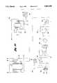
- FIG. 7presents a combination schematic/block diagram of one embodiment of the detector/transmitter unit of the tire parameter monitoring system of the present invention.
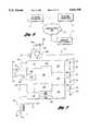
- FIG. 8presents a block diagram of the supervisory link interface for the detector/transmitter of one embodiment of the present invention.
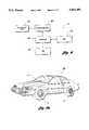
- FIG. 9Apresents the use of the tire pressure monitoring system of one embodiment of the present invention in conjunction with a vehicle
- FIG. 9Bpresents a representation of the location of the detector/transmitter unit within a wheel of one embodiment of the present invention.
- FIG. 9Cpresents a vertical cross-section of one embodiment of the detector/transmitter unit of the tire parameter monitoring system of the present invention.
- FIG. 9Dpresents a bottom view of one embodiment of the detector/transmitter unit of the tire parameter monitoring system of the present invention.
- FIG. 9Epresents a top view of one embodiment of the detector/transmitter unit of the tire parameter monitoring unit of the present invention.
- FIG. 9Fpresents a side view of one embodiment of the detector/transmitter unit of the tire parameter monitoring system of the present invention.
- FIG. 9Gpresents side view of a stud rivet for mounting detector/transmitter unit to a wheel in one embodiment of the tire parameter monitoring system of the present invention
- FIG. 10presents a pictorial lay out of the matrix keypad for the user interface of one embodiment of the tire parameter monitoring system of the present invention
- FIG. 11provides a summary of control commands for the RS232 interface of the receiver/user interface unit of one embodiment of the tire parameter monitoring system of the present invention
- FIG. 12Apresent a vertical cross section of a pressure sensor for use with one embodiment of the tire parameter monitoring system of the present invention
- FIG. 12Bpresents a vertical cross section of the contact pin/brass contact configuration of the pressure monitor of one embodiment of the present invention
- FIG. 12Cpresents a bottom view of the annular lip of the plastic retainer for the pressure monitor used in one embodiment of the tire parameter monitoring system of the present invention
- FIG. 12Dpresents a top view of the diaphragm of the pressure sensor used with one embodiment of the tire parameter monitoring system of the present invention
- FIG. 12Epresents the piezo-resistive element of the pressure sensor used with one embodiment of the tire parameter monitoring system of the present invention
- FIG. 13presents the pressure-resistance characteristic of the piezo-resistive pressure sensor used in one embodiment of the tire parameter monitoring system of the present invention
- FIGS. 14A-14Fpresent a combination flow chart representation and pictorial representation of the user interface/display functions of the user interface of one embodiment of the tire parameter monitoring system of the present invention
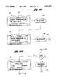
- FIG. 15presents a block diagram representation of the overall communications path of one embodiment of the present invention.
- FIG. 16presents a schematic representation of the connection of a repeater of one embodiment of the present invention.
- FIG. 17presents a perspective view of the transmitter/detector unit of one embodiment of the present invention.
- FIG. 18Apresents a top view of the receiver/user interface unit of one embodiment of the present invention.
- FIG. 18Bpresents a side view of the receiver/user interface unit of one embodiment of the present invention.
- FIG. 19presents a representation of the pulsetrain used for communication in one embodiment of the present invention.
- FIG. 20Apresents the Manchester code format used for communication in one embodiment of the present invention.
- FIG. 20Bpresents the frame format used for communication in one embodiment of the present invention.
- transmitter detector unit 10monitors the pressure and temperature within a tire of a wheeled vehicle and transmits a signal representative of the pressure and temperature via link 12 to receiver user interface unit 14.
- Detector/transmitter unit 10consists of a pressure sensor 16 and a temperature sensor 18 located in proximity to a tire so as to generate electrical signals corresponding to the tire pressure and temperature for input to detector 20.
- Detector 20processes these electrical signals and communicates with transmitter 22 which broadcasts a signal representative of at least the pressure within the tire over link 12.
- the user interface/receiver unit 14consists of receiver unit 24 which accepts the electrical signal from transmitter 22 over link 12 and communicates with a user via user interface 26.
- the user interface 26comprises an LCD display unit for displaying to the user the sensed pressure and/or temperature within the tire.
- Temperature sensor 34 and pressure sensor 32are driven by function generator 30 which emits a periodic signal to each sensor.
- Sensors 32 and 34are designed to vary a parameter of the periodic signal generated by function generator 30 such as the amplitude, phase, frequency, or rate of decay, as a function of the sensed variable, either temperature or pressure.
- Corresponding detection circuits 36 and 38are designed to detect the variation in the corresponding parameter a yield and output 37 which is proportional to temperature in the case of detection circuit 36 and yield an output 39 which is proportional to pressure in the case of detection circuit 38.
- Pressure signal 39 and temperature signal 37are input to pressure calibration unit 40 which corrects the pressure signal based upon the sensed temperature. Temperature 37 is also fed to protocol encoder 46.
- the pressure 41 determined by pressure calibration unit 40is fed to threshold detector 42 which compares this pressure to one or more selected thresholds to determine if the pressure is in an appropriate operating range. In the preferred embodiment, the pressure is compared with an ideal pressure reading to determine if it is within plus or minus three pounds per square inch of that ideal pressure. If the sensed pressure does not fall within this range, an indication signal is sent to protocol encoder 46.
- Protocol encoder 46operates to take the information which has been sensed on the temperature, pressure, and whether or not the pressure violates one or more selected thresholds, converts this information to binary bits, and prepares a block of data to be transmitted consistent with an established protocol.
- This protocolcould be virtually any existing block communications protocol or other means for performing asynchronous communication.
- the individual binary bits generated by protocol encoder 46are sent to Manchester/FSK generator 48.
- This unitconverts these sequential bits of information into bi-phase level baseband transmission waveforms which are modulated using frequency shift keying (FSK).
- FSKfrequency shift keying
- This encoded signalcould be then modulated using a carrier frequency for radio frequency transmission.
- a traditional carrier frequencyin the range of 400 KHz is used.
- a frequency-hop spread spectrum schemecould be used in this regard.
- the present inventionshould be broadly constructed to encompass the choices of waveform encoding, modulation scheme and communication protocol possible.
- FIG. 3a block diagram representation of the receiver and user interface unit 14 is presented.
- the encoded data signal from the communication linkis received by Manchester/FSK decoder 60.
- This decoderserves to convert the modulated and decoded wave forms into binary bits which are transferred to protocol decoder 62.
- Protocol decoder 62strips the underlying databytes from the communicated signal and transfers these bytes as well as other indications provided by the protocol to processor 68.
- processor 68is also connectably in communication with optional serial link 66 such as an RS-232, RS-433 or other similar serial communication standard. This link provides an alternate source of programming and data communication with the processor.
- User interface 70communicates with the processor to receive user input and provide output to the user in the form of displays and indications regarding the operation of the tire pressure monitoring unit. Options for this interface could include voice-activated circuitry providing an audio input/output capability, a bar codes scanner and/or a keypad and display device.
- Temperature sensor 64provides an input to processor 68.
- temperature sensor 64would be placed in a position so as to provide an ambient temperature reading which can be compared with the temperature reading from one or more tires so as to provide a differential temperature sensing capability.
- FIG. 4a block diagram representing the receiver, transmitter and communication link are presented.
- communication link 12is implemented via the components of the vehicle which constitute electrical ground for the vehicle battery and other electrical systems.
- Transmitter 22has signal output 86 referenced to ground 82 isolated from vehicle ground 80. This signal output 86 is connected to vehicle ground 80 which in turn is connected to signal input 88 of receiver 24.
- Receiver 24in turn is provided a ground 84 which is also isolated from vehicle ground 80.
- vehicle ground 80comprises such elements as a metallic wheel on which a tire is mounted, the wheel bearings and axle, as well as the axle supports and vehicle frame.
- these components, their connections, and/or any gaps between these componentsprovide an electromagnetic path for which a signal can travel from transmitter 22 to receiver 24.
- the receiver and transmitteroperate from a common antenna which comprises the vehicle ground.
- this conductive pathwould include a vehicle wheel, the wheel bearings and at least one stationary conductive component of the vehicle such as a vehicle axle or the like.
- the rotating transmitter/detector unitcan communicate a signal to a stationary portion of the vehicle for either direct or remote detection by the receiver/user interface unit.
- a signal repeater 452receives a transmitter signal from transmitter 22 via electromagnetic path 450.
- Repeater 452in turn, retransmits the transmitter signal to receiver 24 via alternative communications link 454.
- This alternative communications linkcould be an RF link, a fiber optic link or a direct connection.
- the repeater 452could simply amplify the incoming signal before retransmission, or it could decode the signal before retransmission in the same or in a different format.
- the repeater 452could add an identification signal to the communication to identify the repeater or the tire which was the source of the communication.
- the repeater 452decodes the digital data from the transmitter 22 and retransmits the data to the receiver 24 in a trinary format as follows.
- the repeater unit 452is connected to a source of voltage 460, such as a 12 volt vehicle battery, through a current limiting element, such as resistor 462.
- a source of voltage 460such as a 12 volt vehicle battery
- resistor 462a current limiting element
- repeater 452provides a load 468 on non-ideal voltage supply 464.
- the repeater 452can, in turn, vary the voltage 466 to multiple levels such as 12 volts, 9 volts and 6 volts used in the trinary scheme of one embodiment of the present invention.
- This trinary schemeis used to convey the data to receiver unit 24 which is provided with a suitable decoder, corresponding to the transmission scheme used.
- the repeater 452is powered by regulating the voltage 466 down to a level, lower than the lowest level of the multiple voltage levels. The choice of the value of current limiting element or resistor 462 is thus based upon the power consumption of the repeater 452, the varying load values 468 and the magnitude of the supply voltage 460.
- Thermistor 64could optionally be located in, or in close proximity to, repeater 452.
- the temperature read by a decoding unit in the repeatercould be sent to receiver 22 along with the data received from transmitter 24.
- CMOS microprocessor unit 100This microprocessor operates in conjunction with 32K RAM chip 102, 16K EPROM 104, address decoding chip 106, databus 108 and address bus 110.
- the microprocessor unit 100is provided with an audio indicator and driver 112 consisting of buzzer 118 and MOS transistor 120.
- Microprocessor unit 100is further provided with an LCD display 114 which is capable of displaying various letters, numbers, and symbols to a user.
- LCD display 114communicates with microprocessor unit 100 via databus 108 and control lines 122.
- Variable resistor 124provides a brightness control for LCD display 114.
- RS232 link driver 126is also connected to microprocessor unit 100.
- This RS232 drivercomprises transmitter/receiver unit 128 and RS232 DIN connector 130.
- Microprocessor unit 100further includes oscillator circuitry 132 for providing the clock signals which drive the microprocessor unit. Further, microprocessor unit 100 is provided with a second oscillator 134 which provides a clock for providing the calendar functions to the microprocessor.
- Capacitor 130 connected to microprocessor unit 100provides a power on reset function such that the operation of the microprocessor is initialized each time the unit is powered up.
- Capacitor 138provides static discharge protection for the microprocessor which is advisable given that the microprocessor utilizes CMOS technology.
- Terminal 140is attached to a vehicle terminal which is a logic low voltage when the vehicle headlights are off and is a logic high voltage when the vehicle headlights are on. This high or low voltage is sensed by driver circuitry 146 which is connected to LCD display unit 114 so as to dim the display if the vehicle headlights are on.
- Power for the unitis provided from the vehicle via vehicle ground 144 and vehicle battery terminal 142.
- Vehicle ground 144 and battery terminal 142are fed to isolated self-oscillating power supply 148.
- Filter 150provides protection against the emission of electromagnetic interference or more specifically radio frequency interference which could plague the operation of other components of the vehicle. Further, filter 150 filters the input signal to the power supply.
- Transformer 152in conjunction with full wave bridge rectifier 144 and voltage regulators 156 and 158 provide a source of five-volt and nine-volt DC power which is isolated from vehicle ground 144.
- Lithium battery 160provides a back up source of power in case the vehicle battery is disconnected.
- bridge rectifier 144could be coupled to vehicle power supply and ground by means of two separate series inductors (one for supply and one for ground). This configurably would provide an isolated ground terminal while filtering R.F. signals from the power supply.
- Receiver and decoder module 162provides the functions of Manchester/FSK decoder 60 from FIG. 3. Receiver and decoder 162 is connected to the vehicle ground 164 serving as the primary communication link between the transmitter unit and the receiver. Temperature sensor 64 is connected to microprocessor unit 100 to provide an ambient temperature measurement as described with reference to FIG. 3.
- FIGS. 20(a) and (b)The Manchester code format utilized by one embodiment of the present invention is shown in FIGS. 20(a) and (b).
- a data framebegins with a synchronization sequence 520 and is followed by three 7-bit words 522. These 7-bit words are followed by a 5-bit word 524 and a "more information" bit. Each data frame is followed by an equal interval of silence as shown in FIG. 20b.
- the 31 bits of the data frameare assigned as follows:
- Bits #1 through #4are designated for use as frame synchronization bits that indicate the location of the first information bit, bit #5, through use of a Manchester coding violation in its #1 and #3 positions. Bit #1 is the first bit of the 31 bit frame that is transmitted.
- Bit #5is the least significant bit (LSB) and is the first information bit transmitted.
- Bit #31is the most significant bit (MSB) and is transmitted last within the 31 bit frame.
- Bits #5 through #30are used for information bits and parity bits; these bits are parsed into 3 words of 6 information bits and 1 parity bit, and 1 word of 4 information bits with parity bit.
- the 6 LSB's of each wordare designated identification information bits, while the MSB is designated an odd parity bit.
- Bit #31is designated for use as a "more information” bit; when set to a "1" it indicates that a subsequent unique frame of information exists; this applies to transponders with memory capacities greater than 31 bits (59 bits, for example); a "0" is used in the final frame to indicate that all information frames have been received, and that the next frame will be Frame #1. A "0" is also employed in single frame applications to indicate that only one unique frame exists.
- the time reporting functioncould be used to indicate such functions as forthcoming reduced power mode of operation if a piezo-electric cell were used as a source of power with the optional capactive storage, programming for additional tires, and further system checks and procedures.
- Error detectionis determined through parity checking and through redundant frame reading as follows.
- Error detectionis determined through the use of Odd Parity in bit positions 11, 18, 25, and 30. Each parity bit is associated with the 6 bits that comprise the word immediately preceding it. A valid word contains an odd number of logic "1's" when the number of occurrences within the 6 bit word and the parity value are summed.
- each of the detector/transmitter units 10corresponds to a separate tire of a vehicle.
- two or more detector/transmitter units 10are present in at least one tire of the vehicle for the purposes of providing redundant operation.
- the communication between the various detector/transmitter units 10 and the receiver 14is carried out asynchronously in the form of variable length packets of information. Eight bits of information in each data packet correspond to the sensed pressure and eight bits of information correspond to the sensed temperature.
- the particular tire that is the source of the transmissionis identified based upon the phase shift and the signal to noise ratio of the received signal.
- the particular tireis identified by a tire identification pattern sent in the data packets corresponding to that tire.
- each of the detector/transmitter units 10is powered by a battery.
- pressure and transmitter datais transmitted from the detector/transmitter 10 to the receiver/user interface 14 at periodic intervals such as one minute or ten minutes.
- Each of the detector/transmitter unitswould be given a unique eight bit address corresponding to that particular unit. If a scheduled data transmission were not received from a particular unit after one or more periods of operation, the receiver/user interface unit 14 would detect a possible failure of that unit and could provide an indication to the user via the user interface. In one embodiment of the present invention, this unit failure could be conveyed to a vehicle alarm unit (if the vehicle were not moving) indicative of a possible tire theft in progress.
- An alternate source of power for the detector/transmitter units 10could be a piezo-electric element. As the tire rotates during operation of the vehicle, the piezo-electric element could vibrate generating power to the detector/transmitter.
- the detector/transmitter unitwould only send periodic transmissions while the vehicle were moving above a certain velocity. Further, the receiver/user interface 14 would only expect to receive these periodic transmissions when the vehicle velocity were above a certain threshold as sensed by a transducer connected to the speedometer of the vehicle or from a wheel speed sensor used in conjunction with an anti-lock braking system or in conjunction with a magnetic sensor connected to the vehicle drive shaft or the like.
- the piezo-electrical elementcould be provided with a capacitive storage element.
- This capacitive storage elementcould provide sufficient power to provide power to the sensor for some period of time, possibly seven days or more, while the wheel is not moving.
- the sensor/transmitter unitwould then operate in a power saving mode, such mode communicated to the receiver unit. During this mode, the transmitter 22 would be activated less frequently to avoid excessive drain on the capacitive storage and to provide longer operation while the wheel is stationary.
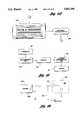
- a detector processor logic array 200is shown as a series of functional sub-blocks 212 through 236.
- This processor unit 200is powered alternatively by battery 201 connected to voltage regulator/voltage transient protector 212 or by piezo-electric battery eliminator 202.
- This piezo-electric battery eliminator 202consists of a piezo-electric element 204 which is connected to weighted arm 206.
- the tire of the vehicle on which the detector/transmitter unit is mountedspins, causing motion and vibration which in turn causes motion in weighted arm 206.
- This excites piezo-electric element 204which generates power to bridge rectifier 208.
- the signal from bridge rectifier 208is in turn filtered by capacitor 210 before it is fed to voltage regulator/voltage transient protector 212.
- Capacitor 210further provides storage of accumulated charge for operation when the tire is no longer in motion.
- Induction coil 244is placed so as to provide an inductively coupled communication link between induction coil 244 and a separate, remotely placed coil.
- This inductive linkprovides a source of communication between the detector/transmitter unit 10 and a remote controller for remote controlling and monitoring of the unit.
- This inductive link 242is connected to service detector 222 of processor 200 via voltage doubling diodes 241.
- this inductive linkis operated at carrier frequency of 400 KHz with a CW modulation scheme with a pulse rate of 10K pulses/sec.
- a sample baseband waveform 500is shown in FIG. 19. Twenty pulses followed by 3 msec of silence provide synchronization. Four bits of information are transmitted LSB to MSB where a binary "0" is represented by 40 pulses followed by 2 ms of silence and a binary "1" is represented by 60 pulses followed by 2 ms of silence.
- processor 200further comprises programmable logic array 226 EPROM 228 and clock oscillator circuitry 224 connected to external clock circuitry 246.
- Manchester code generator 232, service code identifier 234, ID code identifier 236 and FSK generator 230generate the transmitted wave form to be sent over the communications link.
- FSK generator 230is connected via resonant impedance matching network 238 to vehicle ground 240.
- Processor 200further comprises analog to digital converters 216, 218 and 220.
- Thermistors 258 and 254 in conjunction with capacitors 256 and 252are configured so as to provide an R-C time constant which varies with temperature.
- the rate of increase of voltage on line 257 as read by A to D converter 216as a function of the resistance of thermistor 258 and thus a function of the temperature of thermistor 258.
- a to D converter 218reads the voltage on line 253 which is a function of the temperature of thermistor 254.
- Pressure within a tireis determined based upon a similar RC circuit comprising resistor 250 and capacitive pressure transducer 248.
- the rate of increase of the voltage on line 249, as read by A to D converter 220will be a function of the capacitance of capacitive pressure transducer 248 and thus a function of the pressure to which it is exposed.
- FIG. 8a block diagram of the supervisory feature of the detector/transmitter unit 10 of the present invention is shown.
- Detector processor 200is connected to detector ROM 304 and detector RAM 306. Further, the processor 200 communicates with a remote control device shown over supervisory link 300 via decoder/encoder 302.
- supervisory link 300is implemented by the inductive link described in conjunction with FIG. 7.
- Unique 4-bit patternsinitiate the functions of dumping and storing various system parameters including the tire number, transmitter unit ID number, and also including the various pressure and temperature thresholds and nominal values, if applicable.
- remote control via the supervisory linkmay allow the user to change the controller configuration, for example, switch the processor from receiving inputs from one A to D converter or another.
- a test programcould be initiated for determining whether or not the sensor or alternately the battery is operating properly.
- the usercould dump the system ROM or RAM or alternately store additional data in the system RAM.
- the remote usercould dump additional system information including the vehicle number, the serial number, the production date of the software in the ROM or other system information.
- Vehicle 308is provided with a receiver/user interface unit 14 which communicates with individual tire parameter detector/transmitter units 10 located within each of the tires.
- FIG. 9Ca vertical cross section of the detector/transmitter unit 10 of one embodiment of the present invention is shown.
- This unitis housed in phenolic casing 310 attached to stud rivet 312 which is spot welded to the interior wheel rim wall 314 of a vehicle.
- FIG. 9Bpresents a more global view of detector/transmitter unit 10 as is connected to wheel rim wall 314 via stud rivet 312. Lips 316 of wheel rim wall 314 are provided for accepting a tire 315. Rivet 312 is provided with point 318 as shown in FIG. 9A to aid in the penetration welding of the stud rivet 312 to the wheel rim wall 314.
- the bottom of phenolic casing 310is provided with slot 320 for accepting stud rivet 312 as shown in FIG. 9D and FIG. 9F.
- the top of phenolic casing 310provides an access hole 322 as shown in FIG. 9E for allowing the admission of pressurized gas within the tire. The pressurized gas is filtered by filter 324 before admittance to chamber 326.
- Chamber 326is enclosed by capacitive plate 328 which flexes in response to the pressure of the admitted gas.
- This capacitive plate 328is supported by spacers 330 above ceramic substrate 332 on which is deposited a conducive coating supplying second capacitive plate 329.
- This ceramic substratealso supports components 334 which make up the circuitry of detector/transmitter unit.
- detector 10is powered by battery 340 which is connected to circuitry 334 via pin 336 in battery connector 338.
- Antenna connection 342 from the transmitter circuitis conductively attached to stud rivet 312 for conduction with the electromagnetic path.
- Detector/transmitter 10is located within the valve cap 472 for the tire stem 476.
- the cap 472could be in electromagnetic communication with the wheel rim 474 via spring 470.
- this cap 472could be in electromagnetic communication with the wheel rim via a special conductive rubber tire stem. In this case, spring 470 could be eliminated.
- FIG. 10the matrix key pad 116 from FIG. 5 is shown in more detail. The functions of the key pad are described in detail with respect to FIGS. 14A-F.
- FIG. 11presents the various control commands to be used in conjunction with the RS232 interface of the receiver/user interface unit 14 presented in FIG. 5. Before any command can be issued to the receiver/user interface unit 14, a capital V must be sent followed by the eight character password followed by a carriage return.
- a capital C followed by a carriage returndenotes a command which initiates the receiver/user interface unit to reply with the software version and serial number.
- a capital D followed by 24 additional characters and a carriage returninstructs the receiver/user interface unit 14 to program the 24 character data string represented by small d's in FIG. 11 as the vehicle identification code such as the VIN number used in North American automobiles.
- the receiver/user interface unit 14which contains the addresses and labels for up to 256 tires. If a capital L is sent followed by a two number combination BB followed by a comma and followed by a second two number combination EE and a carriage return, the receiver/user interface responds by listing all of the tire alarms, meaning each of the alarm conditions which occurred from month BB to month EE.
- the receiver/user interface 14responds by storing the eight characters represented by lower case d's as the password for the system. This password serves as a security check for the RS232 link such that only authorized users may access the control commands presented herein.
- the receiver/user interface unit 14programs a new date wherein the two digit number MM is the month, the two digit number DD is the day and the two digit number YY is the year.
- the receiver/user interface unit 14is initiated to enter a programmed time wherein the two digit number HH represents the hour and the two digit number MM represents the minute.
- the receiver/user interface unit 14is instructed to program a particular tire number and label wherein the first eight characters represented by a lower case d are the tire number and wherein the last eight characters represented by a lower case d are the label.
- the receiver/user interface unit 14is instructed to output all events that have occurred that are stored in memory without resetting the memory.
- the receiver/user interface unit 14is instructed to output the time and date if the number sent is 1, is instructed to output all tires and labels if the number sent is 2, is instructed to output the vehicle ID number if the number sent is 3, is instructed to output the log number if the number sent is 4, and is instructed to output the driver number if the number sent is 5.
- FIG. 12AA vertical cross section of the piezo-resistive pressure sensor is shown in FIG. 12A.
- Piezo-resistive layer 360is supported by diaphragm 362.
- Diaphragm 362is constructed of silicon liquid crystal polymer or any temperature stable flexible plastic which operates over an automotive temperature range.
- Diaphragm 362is in turn supported by plastic retainer 364 which has a pressure inlet 366. This pressure inlet allows the admission of pressurized gas which in turn deforms diaphragm 362 causing the expansion of the surface of piezo-resistive layer 360.
- piezo-resistive layer 360Electrical contact to piezo-resistive layer 360 is made in conjunction with contact pins 368. These contact pins 368 are supported by plastic retainer 364 and are electrically coupled to brass contact 370 as shown in FIG. 12B. These brass contacts are diametrically spaced about annular lip 372 of plastic retainer 364. These brass contacts in turn are in electrical contact with silver contacts 374 which are mounted diametrically on diaphragm 362. As shown in FIG. 12 or alternatively, the brass contacts 370 are in direct electrical contact with the piezo-resistive layer 360 as shown in FIG. 12E. Piezo-resistive layer 360 is constructed of 20% molybdenum disulfide, 40% activated N-type semiconductor and 40% alkyd or silicon binder.
- the increase of pressure at pressure inlet 366causes an increase in resistance of the piezo-resistive layer as sensed between contact pins 368 as shown in FIG. 13.
- this resistancecan be measured in a variety of ways known to those of ordinary skill in the art and converted into pressure by a linear offset and scaling constant if operated over a sufficiently small range of pressures.
- the resistance as a function of pressurecan be stored in a look-up table format for proper Calibration, and a given value of resistance can then be equated with its corresponding pressure based upon this calibration curve.
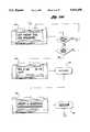
- FIGS. 14A through 14FThe programming of the receiver/user interface unit 14 by means of the matrix keyboard unit 116 shown in FIG. 10 as well as the operation of the LCD display unit 114 is illustrated by FIGS. 14A through 14F.
- display one as shown in block 400is shown on LCD display unit 114.
- This display 400presents the model number of the tire pressure monitoring system as well as the version of the software. If this is the first time that the unit has been turned on, meaning that the unit has not been previously programmed, then the unit waits for five seconds as shown on block 404 and proceeds to display two as shown in block 406. If, however, the unit has previously been programmed either by user input or automatically by the system, the software proceeds to point W 402 in FIG. 14D.
- Display two in block 406prompts the user to enter the date. The user then enters the date numerically using the numbers of the keypad shown in FIG. 10 followed by the enter key as shown in block 408.
- the systemthen responds by presenting display three as shown in block 410.
- Display threeprompts the user to enter the time.
- the userthen enters the time, again using the numeric keys of the keypad shown in FIG. 10 followed by the enter key as shown in block 412.
- the systemthen responds by presenting display four as shown in block 414 of FIG. 14B.
- the systemthen responds by presenting display six as shown in block 424 which prompts the user to enter the sensor number and label.
- the userresponds by entering the tire number and a label designation such as left front, right front, left rear, right rear or spare as shown on the keypad presented in FIG. 10 followed by the enter key as shown in block 426. If this is the last tire to be programmed, then the program proceeds to point B of FIG. 14C. If, however, this is not the last tire to be programmed, the program returns back to block 424 with display six.
- point Bdirects the software to present display seven as shown in block 428.
- Display sevenprompts the user to choose between degrees centigrade or degrees Fahrenheit for temperature displays. The user then enters one for degrees centigrade displays or two for degrees fahrenheit displays followed by the enter key as shown in block 430.
- the programthen responds by presenting display eight as shown in block 432. Display eight prompts the user to choose between displaying the pressure in pounds per square inch or kilipascals per gram. The user responds by pressing one if psi are selected or pressing two if kpg are selected followed by the enter key as shown in block 434.
- the initial programmingbeing then completed, the program then proceeds to point W 402 presented in FIG. 14D.
- the programbegins by determining if any of the tires are in an alarm condition. If no tires are in an alarm condition, the program presents its operational display--display nine as shown in block 436. This display presents a heading for the system as well as the date and time. It should be noted that the program continually scans for alarm conditions being received as shown by the program returning to point W 402.
- the systemresponds by flashing the tire alarm display in providing an audio alarm from buzzer 118 presented in FIG. 5 as shown in block 438.
- One such tire alarm displayis presented in display 10 shown in block 440 of FIG. 14E.
- the label "left front tire”is shown as well as the particular alarm condition, in this case, low pressure. It should be noted that display ten persists until the clear or problem fixed keys are pressed at which point the program reverts back to point W of FIG. 14D. If the left arrow key is pressed, then the program presents display eleven as shown in block 442.
- This displaypresents the tire number as well as the temperature and pressure as read for that particular tire.
- the programthen waits for ten seconds and presents display 12 as shown in block 444.
- Block 444prompts the user to enter the driver number and then press enter as shown in block 446.
- the programthen proceeds to present display thirteen as shown in block 446 of FIG. 14F. Display thirteen prompts the user to enter the route number and then press the enter key as shown in block 448.
- the programthen proceeds back to display ten of FIG. 14E as shown in block 440, the alarm display.
- the LCD display unit 114 and matrix keypad 116 of receiver/user interface unit 14 of the present inventioncould be located at various points within the vehicle.
- the functionality of devices 114 and 116could be incorporated into existing vehicle display and input units. Further, these devices 114 and 116 could be housed in a separate unit 500 as shown in FIGS. 18a and 18b. This separate unit could be mounted in such positions as a vehicle dashboard, a vehicle rearview mirror or headliner, a vehicle center console or a vehicle visor. Additional functions and devices could be integrated into this unit 500 such as a radar detector or a vehicle compass.
Landscapes
- Engineering & Computer Science (AREA)
- Mechanical Engineering (AREA)
- Computer Networks & Wireless Communication (AREA)
- Arrangements For Transmission Of Measured Signals (AREA)
- Measuring Fluid Pressure (AREA)
Abstract
Description
______________________________________ Word 1Tire Number Word 2Pressure Word 3Temperature Word 45, 6 and 7 Trailer Serial No. ______________________________________ Report Conditions Words
Claims (23)
Priority Applications (1)
| Application Number | Priority Date | Filing Date | Title |
|---|---|---|---|
| US08/466,219US5663496A (en) | 1993-08-03 | 1995-06-06 | Tire monitoring via an electromagnetic path including the ground plan of a vehicle |
Applications Claiming Priority (2)
| Application Number | Priority Date | Filing Date | Title |
|---|---|---|---|
| US08/101,379US5473938A (en) | 1993-08-03 | 1993-08-03 | Method and system for monitoring a parameter of a vehicle tire |
| US08/466,219US5663496A (en) | 1993-08-03 | 1995-06-06 | Tire monitoring via an electromagnetic path including the ground plan of a vehicle |
Related Parent Applications (1)
| Application Number | Title | Priority Date | Filing Date |
|---|---|---|---|
| US08/101,379DivisionUS5473938A (en) | 1993-08-03 | 1993-08-03 | Method and system for monitoring a parameter of a vehicle tire |
Publications (1)
| Publication Number | Publication Date |
|---|---|
| US5663496Atrue US5663496A (en) | 1997-09-02 |
Family
ID=22284357
Family Applications (3)
| Application Number | Title | Priority Date | Filing Date |
|---|---|---|---|
| US08/101,379Expired - Fee RelatedUS5473938A (en) | 1993-08-03 | 1993-08-03 | Method and system for monitoring a parameter of a vehicle tire |
| US08/466,219Expired - LifetimeUS5663496A (en) | 1993-08-03 | 1995-06-06 | Tire monitoring via an electromagnetic path including the ground plan of a vehicle |
| US08/465,763Expired - LifetimeUS5741966A (en) | 1993-08-03 | 1995-06-06 | Method and system for monitoring a parameter of a vehicle tire |
Family Applications Before (1)
| Application Number | Title | Priority Date | Filing Date |
|---|---|---|---|
| US08/101,379Expired - Fee RelatedUS5473938A (en) | 1993-08-03 | 1993-08-03 | Method and system for monitoring a parameter of a vehicle tire |
Family Applications After (1)
| Application Number | Title | Priority Date | Filing Date |
|---|---|---|---|
| US08/465,763Expired - LifetimeUS5741966A (en) | 1993-08-03 | 1995-06-06 | Method and system for monitoring a parameter of a vehicle tire |
Country Status (7)
| Country | Link |
|---|---|
| US (3) | US5473938A (en) |
| EP (1) | EP0711229A4 (en) |
| JP (1) | JPH09503971A (en) |
| AU (1) | AU7481294A (en) |
| CA (1) | CA2168665A1 (en) |
| NO (1) | NO960483L (en) |
| WO (1) | WO1995003947A1 (en) |
Cited By (41)
| Publication number | Priority date | Publication date | Assignee | Title |
|---|---|---|---|---|
| US5827957A (en)* | 1996-03-22 | 1998-10-27 | Mercedes-Benz Ag | Method and apparatus for evaluating vehicle tire condition by comparing tire operating parameters with present limits overtime |
| EP0799729A3 (en)* | 1996-04-03 | 1999-03-24 | Ssi Technologies, Inc. | Method and apparatus for synchronizing to a data stream for an inductively coupled transponder |
| US6243007B1 (en) | 1999-12-01 | 2001-06-05 | Mclaughlin John T. | Tire condition monitoring system |
| WO2001070520A1 (en)* | 2000-03-22 | 2001-09-27 | Beru Aktiengesellschaft | Device mounted on vehicles with pneumatic-tired wheels, for use in a tire pressure monitoring system |
| US6438467B1 (en)* | 2001-01-02 | 2002-08-20 | Trw Inc. | Remote control convenience and information conveyance system associated with a vehicle |
| US20030201044A1 (en)* | 2002-04-26 | 2003-10-30 | Tuv Automotive Gmbh | Pneumatic tire mountable of a wheel rim and sensor net, rotation measurement unit and vehicle monitoring system for such tire |
| US6694807B2 (en)* | 2002-01-09 | 2004-02-24 | Lite-On Automotive Corporation | Wheel rim having a tire sensor for a pneumatic tire |
| US20040168512A1 (en)* | 2001-06-15 | 2004-09-02 | Mcewan Thomas E. | Radar monitoring system for tires and wheels |
| US20050104722A1 (en)* | 2003-11-18 | 2005-05-19 | Tom Tang | Universal tire pressure monitor |
| US6921197B2 (en)* | 2001-07-24 | 2005-07-26 | Thomas Aubel | Method and system for measuring temperature and monitoring vehicle tire operation, and vehicle tire and method for introducing a temperature sensor into a vehicle tire |
| EP1338446A3 (en)* | 2002-02-18 | 2005-07-27 | Toyota Jidosha Kabushiki Kaisha | Vehicle tire information obtaining apparatus and tire information processing apparatus |
| US20050229691A1 (en)* | 2004-04-19 | 2005-10-20 | Shaw Mark L | Motion sensing for tire pressure monitoring |
| US20050231433A1 (en)* | 2002-03-01 | 2005-10-20 | Lear Corporation | Antenna for tire pressure monitoring wheel electronic device |
| US20050229710A1 (en)* | 2003-08-11 | 2005-10-20 | O'dowd John | Capacitive sensor |
| US20050285728A1 (en)* | 2004-06-29 | 2005-12-29 | Tyndall Patrick A | Power conversion from piezoelectric source |
| US20060028333A1 (en)* | 2004-08-04 | 2006-02-09 | Tyndall Patrick A | Power conversion from piezoelectric source with multi-stage storage |
| US20060243043A1 (en)* | 2001-02-16 | 2006-11-02 | Automotive Technologies International, Inc. | Tire-Mounted Energy Generator and Monitor |
| US20060254349A1 (en)* | 2005-05-12 | 2006-11-16 | Michelin Recherche Et Technique S.A. | Method of securing a tire-based unit of a tire condition sensing system to a rim and an associated apparatus |
| US20060256691A1 (en)* | 2005-05-13 | 2006-11-16 | Yukio Miura | Receiving device and tire pressure monitoring system |
| US20060290579A1 (en)* | 2002-04-24 | 2006-12-28 | Mineral Lassen Llc | Wireless communication device having conductive elements antenna |
| US7161476B2 (en) | 2000-07-26 | 2007-01-09 | Bridgestone Firestone North American Tire, Llc | Electronic tire management system |
| WO2007039607A1 (en)* | 2005-10-06 | 2007-04-12 | Societe De Technologie Michelin | Hydrostatic-pressure-sensitive actuator |
| US20080018445A1 (en)* | 2004-12-24 | 2008-01-24 | The Yokohama Rubber Co., Ltd | Vehicle Abnormality Detection Method and Device Thereof and Sensor Unit Thereof |
| GB2461928A (en)* | 2008-07-18 | 2010-01-20 | Beru F1 Systems Ltd | Wheel sensor |
| US7693626B2 (en) | 2000-09-08 | 2010-04-06 | Automotive Technologies International, Inc. | Vehicular tire monitoring based on sensed acceleration |
| US20110202229A1 (en)* | 2010-02-18 | 2011-08-18 | General Motors Llc | In-vehicle tire gauge system and methods |
| US8266465B2 (en) | 2000-07-26 | 2012-09-11 | Bridgestone Americas Tire Operation, LLC | System for conserving battery life in a battery operated device |
| WO2012167357A1 (en)* | 2011-06-06 | 2012-12-13 | Sst Wireless Inc. | Method and apparatus for wireless monitoring of tire conditions |
| US8502655B2 (en) | 2011-08-09 | 2013-08-06 | Continental Automotive Systems, Inc. | Protocol misinterpretation avoidance apparatus and method for a tire pressure monitoring system |
| US8576060B2 (en) | 2011-08-09 | 2013-11-05 | Continental Automotive Systems, Inc. | Protocol arrangement in a tire pressure monitoring system |
| US8692661B2 (en) | 2007-07-03 | 2014-04-08 | Continental Automotive Systems, Inc. | Universal tire pressure monitoring sensor |
| US8725330B2 (en) | 2010-06-02 | 2014-05-13 | Bryan Marc Failing | Increasing vehicle security |
| US8742914B2 (en) | 2011-08-09 | 2014-06-03 | Continental Automotive Systems, Inc. | Tire pressure monitoring apparatus and method |
| US8751092B2 (en) | 2011-01-13 | 2014-06-10 | Continental Automotive Systems, Inc. | Protocol protection |
| US8881586B2 (en) | 2011-10-27 | 2014-11-11 | Mobile Awareness, Llc | Tire-condition-ascertaining cartridge |
| US9024743B2 (en) | 2011-08-09 | 2015-05-05 | Continental Automotive System, Inc. | Apparatus and method for activating a localization process for a tire pressure monitor |
| US9446636B2 (en) | 2014-02-26 | 2016-09-20 | Continental Automotive Systems, Inc. | Pressure check tool and method of operating the same |
| US9517664B2 (en) | 2015-02-20 | 2016-12-13 | Continental Automotive Systems, Inc. | RF transmission method and apparatus in a tire pressure monitoring system |
| US9676238B2 (en) | 2011-08-09 | 2017-06-13 | Continental Automotive Systems, Inc. | Tire pressure monitor system apparatus and method |
| US10220660B2 (en) | 2015-08-03 | 2019-03-05 | Continental Automotive Systems, Inc. | Apparatus, system and method for configuring a tire information sensor with a transmission protocol based on vehicle trigger characteristics |
| US11235627B2 (en)* | 2017-10-27 | 2022-02-01 | Compagnie Generale Des Etablissements Michelin | Parameter measurement system for a mounted assembly |
Families Citing this family (172)
| Publication number | Priority date | Publication date | Assignee | Title |
|---|---|---|---|---|
| US5910854A (en) | 1993-02-26 | 1999-06-08 | Donnelly Corporation | Electrochromic polymeric solid films, manufacturing electrochromic devices using such solid films, and processes for making such solid films and devices |
| US5668663A (en) | 1994-05-05 | 1997-09-16 | Donnelly Corporation | Electrochromic mirrors and devices |
| US5585554A (en) | 1994-10-31 | 1996-12-17 | Handfield; Michael | System and method for monitoring a pneumatic tire |
| US5963128A (en)* | 1994-11-22 | 1999-10-05 | Schrader-Bridgeport International, Inc. | Remote tire pressure monitoring system |
| US5541570A (en)* | 1994-12-09 | 1996-07-30 | Force Imaging Technologies, Inc. | Force sensing ink, method of making same and improved force sensor |
| US5656993A (en)* | 1995-05-08 | 1997-08-12 | Semisystems, Inc. | Vehicle wheel condition monitor and data storage system |
| US6891563B2 (en) | 1996-05-22 | 2005-05-10 | Donnelly Corporation | Vehicular vision system |
| US5838229A (en)* | 1995-07-18 | 1998-11-17 | Schrader-Bridgeport International, Inc. | Remote tire pressure monitoring system employing coded tire identification and radio frequency transmission and enabling recalibration upon tire rotation or replacement |
| EP0757942B1 (en)* | 1995-08-08 | 2002-01-09 | Compagnie Generale Des Etablissements Michelin-Michelin & Cie | Device for monitoring the pneumatic tyres of a vehicle |
| US5940120A (en)* | 1995-10-20 | 1999-08-17 | Prince Corporation | Vanity console |
| FR2745755A1 (en)* | 1996-03-06 | 1997-09-12 | Michelin & Cie | METHOD FOR EXPLOITING PRESSURE AND TEMPERATURE MEASUREMENTS IN A TIRE MONITORING SYSTEM |
| WO1997036758A2 (en)* | 1996-03-29 | 1997-10-09 | Michael Handfield | System and method for monitoring a pneumatic tire |
| DE19632150B4 (en)* | 1996-08-09 | 2004-06-09 | Conti Temic Microelectronic Gmbh | Method for checking the air pressure in the tires of motor vehicle wheels |
| US6756892B2 (en) | 1997-01-15 | 2004-06-29 | Algonquin Scientific, Llc | Tire pressure sensing system |
| US6335690B1 (en) | 1997-01-15 | 2002-01-01 | Algonquin Scientific, Llc | Fluid sensing system |
| US6124787A (en)* | 1997-01-15 | 2000-09-26 | Algonquin Scientific, Llc | Tire pressure sensing system |
| US6362732B1 (en) | 1997-01-15 | 2002-03-26 | Algonquin Scientific Llc | Tire pressure sensing system |
| US5790016A (en)* | 1997-01-15 | 1998-08-04 | Algonquin Scientific, Llc | Tire pressure sensing system |
| US6326613B1 (en) | 1998-01-07 | 2001-12-04 | Donnelly Corporation | Vehicle interior mirror assembly adapted for containing a rain sensor |
| US6172613B1 (en) | 1998-02-18 | 2001-01-09 | Donnelly Corporation | Rearview mirror assembly incorporating vehicle information display |
| US6124886A (en) | 1997-08-25 | 2000-09-26 | Donnelly Corporation | Modular rearview mirror assembly |
| US8294975B2 (en) | 1997-08-25 | 2012-10-23 | Donnelly Corporation | Automotive rearview mirror assembly |
| US6058768A (en)* | 1997-12-08 | 2000-05-09 | Huang; Tien-Tsai | Apparatus for detecting pressure condition in a pneumatic tire |
| US6445287B1 (en) | 2000-02-28 | 2002-09-03 | Donnelly Corporation | Tire inflation assistance monitoring system |
| US8288711B2 (en) | 1998-01-07 | 2012-10-16 | Donnelly Corporation | Interior rearview mirror system with forwardly-viewing camera and a control |
| US6693517B2 (en) | 2000-04-21 | 2004-02-17 | Donnelly Corporation | Vehicle mirror assembly communicating wirelessly with vehicle accessories and occupants |
| US6329925B1 (en) | 1999-11-24 | 2001-12-11 | Donnelly Corporation | Rearview mirror assembly with added feature modular display |
| US6477464B2 (en) | 2000-03-09 | 2002-11-05 | Donnelly Corporation | Complete mirror-based global-positioning system (GPS) navigation solution |
| US6034596A (en)* | 1998-09-15 | 2000-03-07 | Smith; Julian | Motor vehicle tire pressure and temperature sensing system |
| JP3499470B2 (en)* | 1998-12-25 | 2004-02-23 | トヨタ自動車株式会社 | Wheel state related information supply device and tire abnormality state notification device |
| US6175302B1 (en)* | 1999-04-02 | 2001-01-16 | Tien-Tsai Huang | Tire pressure indicator including pressure gauges that have a self-generating power capability |
| US7084749B1 (en)* | 1999-07-26 | 2006-08-01 | Prince Technology Corporation | Remote display system with independent power source |
| DE19941953A1 (en)* | 1999-09-03 | 2001-03-08 | Volkswagen Ag | Method and device for displaying vehicle states of a motor vehicle |
| US6297732B2 (en)* | 1999-09-08 | 2001-10-02 | Precision Navigation, Inc. | Radar/laser detection device with multi-sensing and reporting capability |
| JP3510164B2 (en)* | 1999-10-06 | 2004-03-22 | トヨタ自動車株式会社 | Wheel state information supply device and wheel state information supply / reception device |
| US6292096B1 (en) | 1999-12-15 | 2001-09-18 | Trw Inc. | Apparatus and method for transmitting data in a tire condition sensing system |
| US7370983B2 (en) | 2000-03-02 | 2008-05-13 | Donnelly Corporation | Interior mirror assembly with display |
| AU2001243285A1 (en) | 2000-03-02 | 2001-09-12 | Donnelly Corporation | Video mirror systems incorporating an accessory module |
| US7167796B2 (en) | 2000-03-09 | 2007-01-23 | Donnelly Corporation | Vehicle navigation system for use with a telematics system |
| FR2807363B1 (en) | 2000-04-07 | 2003-02-07 | Trw France | TIRE PARAMETER MEASUREMENT SENSOR AND MEASUREMENT SYSTEM COMPRISING THE SAME |
| DE10025561A1 (en) | 2000-05-24 | 2001-12-06 | Siemens Ag | Self-sufficient high-frequency transmitter |
| NO20013182L (en) | 2000-06-26 | 2001-12-27 | Nokian Tyres Plc | System and method for converting and transmitting tire operating data |
| US6825758B1 (en) | 2000-06-26 | 2004-11-30 | Nokian Tyres Plc | System for detecting and communicating operational characteristics of tires telecommunicationally and a method therefor |
| US6580364B1 (en) | 2000-07-06 | 2003-06-17 | Trw Inc. | Apparatus and method for tracking an abnormal tire condition |
| DE60142907D1 (en) | 2000-07-26 | 2010-10-07 | Bridgestone Americas Tire | ELECTRONIC TIRE HANDLING SYSTEM |
| EP1328420A4 (en)* | 2000-09-21 | 2009-03-04 | American Calcar Inc | TECHNIQUE FOR OPERATING A VEHICLE EFFECTIVELY AND SECURELY |
| JP2002104149A (en)* | 2000-09-29 | 2002-04-10 | Toyota Motor Corp | Wheel rotation state detector |
| DE10052307A1 (en)* | 2000-10-21 | 2002-05-02 | Bayerische Motoren Werke Ag | Error reporting system for a vehicle |
| GB0030405D0 (en)* | 2000-12-13 | 2001-01-24 | Transense Technologies Plc | Wheel condition monitoring system |
| US6414592B1 (en)* | 2001-01-02 | 2002-07-02 | Trw Inc. | Tire condition sensor communication with tire location provided via manually inputted update |
| AU2002251807A1 (en) | 2001-01-23 | 2002-08-19 | Donnelly Corporation | Improved vehicular lighting system for a mirror assembly |
| US7581859B2 (en) | 2005-09-14 | 2009-09-01 | Donnelly Corp. | Display device for exterior rearview mirror |
| US7255451B2 (en) | 2002-09-20 | 2007-08-14 | Donnelly Corporation | Electro-optic mirror cell |
| WO2002066269A2 (en)* | 2001-02-20 | 2002-08-29 | Siemens Vdo Automotive Corporation | Combined tire pressure monitoring and keyless entry receiver |
| US6885283B2 (en)* | 2001-02-20 | 2005-04-26 | Siemens Vdo Automotive Corporation | Combined tire pressure monitoring and keyless entry receiver |
| CA2343489C (en)* | 2001-04-05 | 2007-05-22 | Electrofuel, Inc. | Energy storage device for loads having variable power rates |
| US20040201365A1 (en)* | 2001-04-05 | 2004-10-14 | Electrovaya Inc. | Energy storage device for loads having variable power rates |
| EP1377477B1 (en)* | 2001-04-05 | 2006-12-27 | Electrovaya Inc. | Energy storage device for loads having variable power rates |
| AU2002320270B2 (en) | 2001-07-03 | 2008-06-05 | Clark Davis Boyd | Self-powered switch initiation system |
| US6469621B1 (en)* | 2001-08-16 | 2002-10-22 | Johnson Controls Technology Company | Tire monitor compatible with multiple data protocols |
| DE10140436A1 (en)* | 2001-08-17 | 2003-03-06 | Porsche Ag | Measurement of motor vehicle tire pressures and display of the results in an easy to understand manner, whereby the difference between measured and preset values is displayed, so the driver can easily see if adjustment is needed |
| US6693522B2 (en) | 2001-10-12 | 2004-02-17 | Lear Corporation | System and method for tire pressure monitoring including automatic tire location recognition |
| US6864803B2 (en) | 2001-10-12 | 2005-03-08 | Lear Corporation | System and method for tire pressure monitoring using CDMA tire pressure signals |
| EP1319530B1 (en)* | 2001-12-17 | 2008-03-19 | Honda Giken Kogyo Kabushiki Kaisha | Tire pressure detecting system |
| US6745624B2 (en)* | 2002-02-05 | 2004-06-08 | Ford Global Technologies, Llc | Method and system for calibrating a tire pressure sensing system for an automotive vehicle |
| US20030164759A1 (en)* | 2002-03-01 | 2003-09-04 | Lear Corporation | System and method for tire pressure monitoring with optimal tire pressure indication during tire pressure adjustment |
| US6788193B2 (en) | 2002-03-01 | 2004-09-07 | Lear Corporation | System and method for tire pressure monitoring providing automatic tire location recognition |
| US20030164760A1 (en)* | 2002-03-01 | 2003-09-04 | Lear Corporation | System and method for tire pressure monitoring using vehicle radio |
| US6829924B2 (en)* | 2002-03-01 | 2004-12-14 | Lear Corporation | Tire pressure monitoring system with low frequency initiation approach |
| US7154414B2 (en)* | 2002-03-01 | 2006-12-26 | Lear Corporation | System and method for remote tire pressure monitoring |
| US20030164034A1 (en)* | 2002-03-01 | 2003-09-04 | Lear Corporation | System and method for using a saw based RF transmitter for FM transmission in a TPM |
| US6725712B1 (en) | 2002-03-01 | 2004-04-27 | Lear Corporation | System and method for tire pressure monitoring with automatic tire location recognition |
| US6876265B2 (en)* | 2002-03-01 | 2005-04-05 | Lear Corporation | System and method for using a saw based RF transmitter for AM modulated transmission in a TPM |
| US6647773B2 (en) | 2002-03-01 | 2003-11-18 | Lear Corporation | System and method for integrated tire pressure monitoring and passive entry |
| US6668636B2 (en) | 2002-03-01 | 2003-12-30 | Lear Corporation | System and method for tire pressure monitoring including tire location recognition |
| US6691567B2 (en) | 2002-03-01 | 2004-02-17 | Lear Corporation | System and method for tire pressure monitoring including automatic tire location recognition |
| US7035773B2 (en)* | 2002-03-06 | 2006-04-25 | Fisher-Rosemount Systems, Inc. | Appendable system and devices for data acquisition, analysis and control |
| US7860680B2 (en)* | 2002-03-07 | 2010-12-28 | Microstrain, Inc. | Robotic system for powering and interrogating sensors |
| US7081693B2 (en)* | 2002-03-07 | 2006-07-25 | Microstrain, Inc. | Energy harvesting for wireless sensor operation and data transmission |
| US7173520B2 (en)* | 2002-03-22 | 2007-02-06 | Siemens Vdo Automotive Corporation | System and method for identifying source of RF transmission |
| US20030179086A1 (en)* | 2002-03-25 | 2003-09-25 | Lear Corporation | System for remote tire pressure monitoring with low frequency initiation antenna |
| US6838985B2 (en)* | 2002-03-25 | 2005-01-04 | Lear Corporation | System and method for remote tire pressure monitoring with low frequency initiation |
| US6918674B2 (en) | 2002-05-03 | 2005-07-19 | Donnelly Corporation | Vehicle rearview mirror system |
| US7096727B2 (en)* | 2002-05-10 | 2006-08-29 | Michelin Recherche Et Technique S.A. | System and method for generating electric power from a rotating tire's mechanical energy |
| US7429801B2 (en)* | 2002-05-10 | 2008-09-30 | Michelin Richerche Et Technique S.A. | System and method for generating electric power from a rotating tire's mechanical energy |
| US7329013B2 (en) | 2002-06-06 | 2008-02-12 | Donnelly Corporation | Interior rearview mirror system with compass |
| AU2003237424A1 (en) | 2002-06-06 | 2003-12-22 | Donnelly Corporation | Interior rearview mirror system with compass |
| WO2004002759A1 (en)* | 2002-06-28 | 2004-01-08 | Pirelli Pneumatici S.P.A. | System and monitoring characteristic parameters of a tyre |
| US20040056763A1 (en)* | 2002-07-02 | 2004-03-25 | Martin Fischer | Method for protecting against theft of auto tires |
| US6868358B2 (en)* | 2002-07-24 | 2005-03-15 | The Goodyear Tire & Rubber Company | Method for processing information in a tire pressure monitoring system |
| US6750762B1 (en) | 2002-08-07 | 2004-06-15 | Ford Global Technologies, Llc | Method and system for resetting tire pressure monitoring system for an automotive vehicle |
| US6985076B1 (en) | 2002-08-07 | 2006-01-10 | Ford Global Technologies, Llc | Method and system for detecting the presence of a spare replacement in a tire pressure monitoring system for an automotive vehicle |
| US6771169B1 (en) | 2002-08-07 | 2004-08-03 | Ford Global Technologies, Llc | Tire pressure monitoring system with a signal initiator |
| US6850155B1 (en) | 2002-08-07 | 2005-02-01 | Ford Global Technologies, Llc | Method and system of notifying of overuse of a mini-spare tire in a tire pressure monitoring system for an automotive vehicle |
| US6982636B1 (en) | 2002-08-07 | 2006-01-03 | Ford Global Technologies, Llc | Method and system for mitigating false alarms in a tire pressure monitoring system for an automotive vehicle |
| US6900725B1 (en) | 2002-08-07 | 2005-05-31 | Ford Global Technologies, Llc | Method and system for automatically extending a tire pressure monitoring system for an automotive vehicle to include auxiliary tires |
| US7026922B1 (en) | 2002-08-07 | 2006-04-11 | Ford Global Technologies, Llc | Method and apparatus for automatically identifying the location of pressure sensors in a tire pressure monitoring system |
| US6952160B1 (en)* | 2002-08-07 | 2005-10-04 | Ford Global Technologies, Llc | Method and apparatus, for identifying the location of pressure sensors in a tire pressure monitoring system |
| US6784794B1 (en) | 2002-08-07 | 2004-08-31 | Ford Global Technologies, Llc | Method and apparatus for reminding the vehicle operator to refill the spare tire in a tire pressure monitoring system |
| US7015802B2 (en)* | 2002-08-08 | 2006-03-21 | Forster Ian J | Vehicle tag reader |
| US7050017B2 (en)* | 2002-08-14 | 2006-05-23 | King Patrick F | RFID tire belt antenna system and method |
| JP4016773B2 (en)* | 2002-09-13 | 2007-12-05 | トヨタ自動車株式会社 | Wheel identification information registration support device |
| US7310177B2 (en) | 2002-09-20 | 2007-12-18 | Donnelly Corporation | Electro-optic reflective element assembly |
| WO2004026633A2 (en) | 2002-09-20 | 2004-04-01 | Donnelly Corporation | Mirror reflective element assembly |
| WO2004103772A2 (en) | 2003-05-19 | 2004-12-02 | Donnelly Corporation | Mirror assembly for vehicle |
| US6729180B2 (en)* | 2002-09-25 | 2004-05-04 | Delphi Technologies, Inc. | Packaging for RF signal sensor with battery changing capabilities and method of using |
| GB0222680D0 (en)* | 2002-10-01 | 2002-11-06 | Haswell Moulding Technologies | Power generation |
| JP2004155222A (en)* | 2002-11-01 | 2004-06-03 | Pacific Ind Co Ltd | Tire state monitoring device |
| JP2004168185A (en)* | 2002-11-20 | 2004-06-17 | Honda Motor Co Ltd | Tire pressure monitoring device |
| US6919819B1 (en)* | 2003-02-14 | 2005-07-19 | Power Data Communication Co., Ltd. | Sunshade board |
| JP4255301B2 (en)* | 2003-03-31 | 2009-04-15 | 横浜ゴム株式会社 | Mounting structure for tire electronic components |
| US7446924B2 (en) | 2003-10-02 | 2008-11-04 | Donnelly Corporation | Mirror reflective element assembly including electronic component |
| US7308341B2 (en) | 2003-10-14 | 2007-12-11 | Donnelly Corporation | Vehicle communication system |
| US20050093686A1 (en)* | 2003-10-30 | 2005-05-05 | Lear Corporation | Tire pressure monitoring sensor diagnosis via vehicle antitheft and entry system |
| US7073377B2 (en)* | 2003-12-11 | 2006-07-11 | Trw Automotive U.S. Llc | Tire parameter sensing system with signal relay device and associated method |
| KR100577696B1 (en)* | 2003-12-15 | 2006-05-10 | 삼성전자주식회사 | Image liquid crystal display device that can have a uniform cell gap |
| KR100555659B1 (en)* | 2003-12-22 | 2006-03-03 | 삼성전자주식회사 | Self-generated sensing module and tire pressure monitoring system using it |
| DE102004002910B4 (en)* | 2004-01-20 | 2017-01-26 | Continental Automotive Gmbh | Device for converting energy of a rotating wheel and motor vehicle wheel with such a conversion device |
| DE102004010010B3 (en)* | 2004-03-01 | 2005-10-13 | Siemens Ag | Method and monitoring device for monitoring a wheel characteristic of a wheel |
| US7467035B2 (en)* | 2004-05-18 | 2008-12-16 | Haldex Brake Products Ltd. | Vehicle control system with redundant storage of vehicle control parameters |
| DE102004026035B4 (en)* | 2004-05-27 | 2008-02-07 | Siemens Ag | Method and device for controlling the operation of a wheel electronics associated with a vehicle wheel |
| JP4211683B2 (en)* | 2004-05-28 | 2009-01-21 | 株式会社デンソー | Communications system |
| US7047800B2 (en)* | 2004-06-10 | 2006-05-23 | Michelin Recherche Et Technique S.A. | Piezoelectric ceramic fibers having metallic cores |
| US7092804B2 (en)* | 2004-07-16 | 2006-08-15 | Ford Global Technologies, Llc | Method and apparatus for providing refill or bleed alerts in a tire pressure monitoring system |
| US20060010961A1 (en)* | 2004-07-19 | 2006-01-19 | Alex Gibson | Method and apparatus for detecting leakage rate in a tire pressure monitoring system |
| US6904795B1 (en)* | 2004-09-14 | 2005-06-14 | Lear Corporation | Sealed mounting of tire monitoring assembly |
| FR2876794B1 (en)* | 2004-10-20 | 2007-02-09 | Peugeot Citroen Automobiles Sa | INFLATION PRESSURE CONTROL SYSTEM FOR TIRES OF A MOTOR VEHICLE |
| US7224269B2 (en)* | 2004-12-15 | 2007-05-29 | Ford Global Technologies, Llc | Method and system for resetting tire pressure monitoring system for an automotive vehicle |
| DE102005008022A1 (en)* | 2005-02-22 | 2006-08-31 | Daimlerchrysler Ag | Vehicle tires` pressure monitoring method, involves evaluating signals from sensor units for monitoring pressure of tires and deactivating pressure monitoring, if signals are received or not received within given time interval, respectively |
| CA2605850C (en)* | 2005-04-26 | 2012-03-13 | Cooper Tire & Rubber Company | Rfid transmitter for tires and method of manufacture |
| US7369043B2 (en)* | 2005-05-11 | 2008-05-06 | Ford Global Technologies, Llc | Method and apparatus for automatically identifying the location of pressure sensors in a tire pressure monitoring system |
| EP1883855B1 (en) | 2005-05-16 | 2011-07-20 | Donnelly Corporation | Vehicle mirror assembly with indicia at reflective element |
| CN1876409B (en)* | 2005-06-09 | 2011-07-06 | 浙江吉利控股集团有限公司 | Function Improvement and Expansion Technical Scheme of Tire Pressure Monitoring System |
| US8121754B2 (en)* | 2005-06-10 | 2012-02-21 | Michelin Recherche Et Technique | Inductive coupling of pulses from piezoelectric device |
| US7382239B2 (en)* | 2005-08-23 | 2008-06-03 | Gm Global Technology Operations, Inc. | System and method for improving received signal strength for an in-vehicle wireless communication system |
| US7348878B2 (en)* | 2005-09-29 | 2008-03-25 | International Truck Intellectual Property Company, Llc | Tire pressure monitoring system with permanent tire identification |
| US7260984B2 (en)* | 2005-10-05 | 2007-08-28 | Lv Sensors, Inc. | Power generation utilizing tire pressure changes |
| US7570157B2 (en)* | 2005-10-24 | 2009-08-04 | Ford Global Technologies, Llc | Method and apparatus for adjusting the pressure sensor measurement range in a tire pressure monitoring system |
| EP1949666B1 (en) | 2005-11-01 | 2013-07-17 | Magna Mirrors of America, Inc. | Interior rearview mirror with display |
| US7705717B2 (en)* | 2005-11-30 | 2010-04-27 | Ford Global Technologies | Method and apparatus for receiving signals from a sensor into a tire pressure monitoring system |
| WO2007110934A1 (en)* | 2006-03-28 | 2007-10-04 | Shimadzu Corporation | Thermal mass flow rate meter |
| WO2007127106A2 (en)* | 2006-04-28 | 2007-11-08 | Cooper Tire & Rubber Company | Long range rfid transponder |
| EP2030282B1 (en)* | 2006-06-22 | 2014-04-23 | Cooper Tire & Rubber Company | Magnetostrictive/piezo remote power generation, battery and method |
| JP4821714B2 (en)* | 2006-08-24 | 2011-11-24 | 株式会社デンソー | Tire theft detection device |
| US7421902B2 (en) | 2006-10-13 | 2008-09-09 | Smartire Systems, Inc. | Fluid pressure sensing method and apparatus |
| US7459961B2 (en)* | 2006-10-31 | 2008-12-02 | Avago Technologies Wireless Ip (Singapore) Pte. Ltd. | Voltage supply insensitive bias circuits |
| CN101754873B (en)* | 2007-07-18 | 2014-03-05 | 倍耐力轮胎股份公司 | Method and system for generating electrical energy in a wheel tire |
| DE102008035498A1 (en)* | 2007-08-31 | 2009-03-05 | Continental Teves Ag & Co. Ohg | Tire module with piezosensitive sensor |
| JP4495205B2 (en)* | 2007-11-30 | 2010-06-30 | 富士通テン株式会社 | Eco driving support device |
| US8154418B2 (en) | 2008-03-31 | 2012-04-10 | Magna Mirrors Of America, Inc. | Interior rearview mirror system |
| US9487144B2 (en) | 2008-10-16 | 2016-11-08 | Magna Mirrors Of America, Inc. | Interior mirror assembly with display |
| US8171791B2 (en)* | 2009-05-13 | 2012-05-08 | Robert Bosch Gmbh | Rotation sensor with onboard power generation |
| US8231060B2 (en)* | 2009-07-02 | 2012-07-31 | Cooper Tire & Rubber Company | Tire antenna for RFID |
| US8330335B2 (en)* | 2009-07-02 | 2012-12-11 | Cooper Tire & Rubber Company | Piezo magnetostrictive device |
| US8659412B2 (en)* | 2009-12-10 | 2014-02-25 | Continental Automotive Systems, Inc. | Tire pressure monitoring apparatus and method |
| US20110198401A1 (en)* | 2010-02-12 | 2011-08-18 | Cooper Tire & Rubber Company | Wireless antenna for RFID for tires |
| US9385420B2 (en)* | 2010-02-12 | 2016-07-05 | Cooper Tire & Rubber Company | Wireless antenna for RFID tires |
| US8717181B2 (en) | 2010-07-29 | 2014-05-06 | Hill-Rom Services, Inc. | Bed exit alert silence with automatic re-enable |
| EP2420957B1 (en) | 2010-08-18 | 2015-01-14 | Cooper Tire & Rubber Company | Conductive rubber antenna for RFID tag used in tires |
| US8752784B2 (en) | 2011-04-07 | 2014-06-17 | Lord Corporation | Aircraft rotary wing motion control and instrumented motion control fluid device |
| RU2509656C1 (en)* | 2012-09-20 | 2014-03-20 | Михаил Михайлович Закатов | Passive automotive tire air pressure and temperature metre |
| US8704388B1 (en)* | 2012-11-26 | 2014-04-22 | International Business Machines Corporation | Generating electrical current by deflection of a flexible support member |
| KR101349684B1 (en)* | 2012-12-21 | 2014-01-09 | 현대오트론 주식회사 | Tire pressure monitoring module, tire pressure monitoring system comprising the same |
| US8935069B2 (en) | 2013-02-28 | 2015-01-13 | Bendix Commercial Vechicle Systems LLC | System and method for transmitting a tire pressure status signal to a vehicle ECU |
| DE102013114726A1 (en)* | 2013-12-20 | 2015-06-25 | Huf Hülsbeck & Fürst Gmbh & Co. Kg | Method and device for operating a tire pressure monitoring device |
| DE102014110184A1 (en) | 2014-07-18 | 2016-01-21 | Infineon Technologies Ag | Tire pressure sensor modules, tire pressure monitoring system, wheel, method and computer programs for providing tire pressure related information |
| GB2557620A (en)* | 2016-12-12 | 2018-06-27 | Wheely Safe Ltd | Tyre pressure monitoring system |
| US10442257B2 (en)* | 2017-07-21 | 2019-10-15 | GM Global Technology Operations LLC | Determining tire leak rate |
| TWI668418B (en)* | 2017-11-24 | 2019-08-11 | 為升電裝工業股份有限公司 | Warrant recording system and setting apparatus thereof for tire pressure detector |
| US11424816B2 (en)* | 2018-05-15 | 2022-08-23 | Pratt & Whitney Canada Corp. | Communication module for transmission of aircraft data |
| JP1632800S (en)* | 2018-09-06 | 2019-06-03 | ||
| US11560022B2 (en) | 2018-12-12 | 2023-01-24 | Tdk Corporation | Rotatable smart wheel systems and methods |
Citations (105)
| Publication number | Priority date | Publication date | Assignee | Title |
|---|---|---|---|---|
| US3016515A (en)* | 1959-08-31 | 1962-01-09 | Metallurg Resources Inc | Vehicle tire pressure alarm apparatus |
| US3247719A (en)* | 1963-10-01 | 1966-04-26 | Chelner Herbert | Strain decoupled transducer |
| US3261001A (en)* | 1962-01-09 | 1966-07-12 | Electro Mechanical Res Inc | Telemetering decoder system |
| US3309463A (en)* | 1963-04-25 | 1967-03-14 | Gen Dynamics Corp | System for locating the end of a sync period by using the sync pulse center as a reference |
| US3329934A (en)* | 1964-10-02 | 1967-07-04 | Andrew C Wooden | Device for indicating loss of tire air pressure |
| US3596509A (en)* | 1966-03-26 | 1971-08-03 | Giulio Raffaelli | Apparatus for measuring tire pressures |
| US3705385A (en)* | 1969-12-10 | 1972-12-05 | Northern Illinois Gas Co | Remote meter reading system |
| US3806471A (en)* | 1968-04-29 | 1974-04-23 | R Mitchell | Pressure responsive resistive material |
| US3810090A (en)* | 1972-09-15 | 1974-05-07 | Avco Corp | Pneumatic tire low pressure monitoring and warning system |
| US3890595A (en)* | 1971-05-21 | 1975-06-17 | Safety Res & Eng | Alarm system for pneumatic tires |
| US3895347A (en)* | 1973-09-10 | 1975-07-15 | Bridgestone Tire Co Ltd | System for transmitting information of reduced pneumatic pressure of tire |
| US3993939A (en)* | 1975-01-07 | 1976-11-23 | The Bendix Corporation | Pressure variable capacitor |
| US4048614A (en)* | 1975-08-18 | 1977-09-13 | Shumway Harry J | Low tire pressure warning device |
| US4054540A (en)* | 1973-02-26 | 1977-10-18 | Dynacon Industries, Inc. | Pressure sensitive resistance and process of making same |
| US4057783A (en)* | 1973-11-07 | 1977-11-08 | Jaeger | Device for transmitting the condition of a switch between two parts in relative rotary movement |
| US4067235A (en)* | 1974-11-27 | 1978-01-10 | Consolidated Freightways, Inc. | Method and apparatus for measuring air pressure in pneumatic tires |
| US4074227A (en)* | 1974-11-15 | 1978-02-14 | Kalmus Henry P | Tire pressure indicator |
| FR2225300B3 (en) | 1973-04-12 | 1978-02-17 | Godfernaux Emile | |
| US4101872A (en)* | 1974-06-18 | 1978-07-18 | Aboyne Pty. Limited | Fire detection system |
| US4104595A (en)* | 1976-12-27 | 1978-08-01 | Borg-Warner Corporation | Signal translating circuit for variable area capacitive pressure transducer |
| US4119944A (en)* | 1977-06-27 | 1978-10-10 | Jesse Britton Smith | Vehicular tire air pressure measuring system |
| US4137520A (en)* | 1978-05-12 | 1979-01-30 | Deveau Levi J | Tire pressure indicator system |
| US4160234A (en)* | 1976-03-29 | 1979-07-03 | Gould Inc. | Abnormal tire condition sensing system |
| US4163208A (en)* | 1975-12-18 | 1979-07-31 | Merz Ernest J | Automatic wireless tire pressure monitoring system |
| US4186377A (en)* | 1976-03-11 | 1980-01-29 | Safety Research & Engineering Corporation | Method and apparatus for monitoring tire pressure |
| US4237728A (en)* | 1979-04-30 | 1980-12-09 | Gould Inc. | Low tire warning system |
| US4263579A (en)* | 1979-11-15 | 1981-04-21 | Cgs Research And Development, Inc. | Tire pressure alarm |
| US4276538A (en)* | 1980-01-07 | 1981-06-30 | Franklin N. Eventoff | Touch switch keyboard apparatus |
| US4276540A (en)* | 1977-10-06 | 1981-06-30 | Habib Jr Fred G | Remote cycle alarm system |
| US4300118A (en)* | 1978-02-28 | 1981-11-10 | Bridgestone Tire Company Limited | Tire inner pressure drop alarming service |
| US4301337A (en)* | 1980-03-31 | 1981-11-17 | Eventoff Franklin Neal | Dual lateral switch device |
| US4313483A (en)* | 1978-05-26 | 1982-02-02 | Heinrich Brockmann | Apparatus for regulating the air pressure in tires of cross-country vehicles |
| US4314228A (en)* | 1980-04-16 | 1982-02-02 | Eventoff Franklin Neal | Pressure transducer |
| US4314227A (en)* | 1979-09-24 | 1982-02-02 | Eventoff Franklin Neal | Electronic pressure sensitive transducer apparatus |
| US4314230A (en)* | 1980-07-31 | 1982-02-02 | Raychem Corporation | Devices comprising conductive polymers |
| US4316176A (en)* | 1979-12-26 | 1982-02-16 | Eaton Corporation | Tire pressure monitor and self check system therefore |
| US4328494A (en)* | 1979-12-26 | 1982-05-04 | Richard Goodall | Digital data link for truck weighing applications |
| US4334215A (en)* | 1979-04-27 | 1982-06-08 | Tire-Tronics, Inc. | Continuous heat and pressure surveillance system for pneumatic tires |
| US4334428A (en)* | 1978-05-04 | 1982-06-15 | Fima Raoul G | Apparatus for indicating parameters sensed on a rotatable wheel |
| FR2482287B3 (en) | 1980-05-09 | 1983-03-11 | Salou Alain | |
| US4451714A (en)* | 1983-02-09 | 1984-05-29 | Eventoff Franklin Neal | Spacerless keyboard switch circuit assembly |
| US4468650A (en)* | 1982-09-30 | 1984-08-28 | Kanetsu Kogyo Kabushiki Kaisha | Low tire pressure alarm system |
| US4467641A (en)* | 1980-12-29 | 1984-08-28 | Precision Mechanique Labinal | Device for measuring a parameter on a rotary element, and in particular for measuring the pressure of a pneumatic tire on a wheel |
| US4489599A (en)* | 1982-04-10 | 1984-12-25 | Itt Industries, Inc. | Device for monitoring the inflation pressure in a tire of a vehicle wheel |
| US4494106A (en)* | 1981-02-18 | 1985-01-15 | Grathnail Development Company Limited | Pressure monitor |
| US4510484A (en)* | 1983-03-28 | 1985-04-09 | Imperial Clevite Inc. | Piezoelectric reed power supply for use in abnormal tire condition warning systems |
| US4531112A (en)* | 1982-06-17 | 1985-07-23 | Thomas Stephen E | Method and apparatus for transmitting from within a pneumatic wheel assembly |
| FR2504675B1 (en) | 1981-04-28 | 1985-10-18 | Salou Alain | SYSTEM FOR VIEWING, WITHOUT CONTACT, THE EVOLUTION OF A PARAMETER AND APPLICABLE TO MONITORING, PERMANENTLY, THE PRESSURE OF A TIRE |
| US4554528A (en)* | 1982-09-04 | 1985-11-19 | Robert Bosch Gmbh | Vehicle tire pressure monitoring system |
| US4571588A (en)* | 1983-05-23 | 1986-02-18 | Varian Associates, Inc. | Scaling circuit for remote measurement system |
| US4619137A (en)* | 1984-05-26 | 1986-10-28 | Dr. Ing. H.C.F. Porsche, Aktiengesellschaft | Arrangement of a pressure-measuring element |
| US4693112A (en)* | 1985-06-03 | 1987-09-15 | Ferris James E | Air conditioner refrigerant check gauge insert convertible to a tire check gauge |
| US4695823A (en)* | 1984-04-27 | 1987-09-22 | Vernon Roger W | Vehicle tire monitoring apparatus |
| US4703650A (en)* | 1985-07-03 | 1987-11-03 | Compagnie Generale Des Etablissements Michelin | Circuit for the coding of the value of two variables measured in a tire, and device for monitoring tires employing such a circuit |
| US4711130A (en)* | 1985-08-08 | 1987-12-08 | Robert Bosch Gmbh | Pressure measuring element |
| US4717905A (en)* | 1985-05-24 | 1988-01-05 | Roger W. Vernon | Warning system including means for remotely energizing condition sensing device |
| EP0251355A1 (en)* | 1986-05-19 | 1988-01-07 | Neotech Industries, Inc. | Vehicle wheel and tire pressure monitor |
| US4737761A (en)* | 1985-07-03 | 1988-04-12 | Compagnie Generale Des Etablissements Michelin | Feeding of electrical energy to circuits on a wheel for a tire-monitoring device |
| US4742857A (en)* | 1986-10-07 | 1988-05-10 | Techni Guidance, Inc. | Tire pressure sensor and air supply to maintain desired tire pressure |
| US4747761A (en)* | 1985-06-17 | 1988-05-31 | Hitachi, Ltd. | Silencer-carrying rotary vane pump |
| US4749993A (en)* | 1985-02-01 | 1988-06-07 | Dr. Ing. H.C.F. Porsche Aktiengesellschaft | Arrangement for the wireless transmission of measuring signals |
| US4761996A (en)* | 1985-11-23 | 1988-08-09 | Robert Bosch Gmbh | Device for transmitting measuring signals, for example, for the tire pressure, to twin wheels of motor vehicles |
| DE3703128A1 (en) | 1987-02-03 | 1988-08-11 | Continental Gummi Werke Ag | Monitoring method and device for dynamically loaded rubber articles |
| FR2601533B1 (en) | 1986-07-10 | 1988-10-21 | Telemecanique Electrique | HIGH FREQUENCY SIGNAL TRANSCEIVER DEVICE COUPLABLE TO A TRANSMISSION NETWORK |
| US4816802A (en)* | 1985-04-18 | 1989-03-28 | Ben F. Doerksen | Tire pressure monitoring system |
| US4823107A (en)* | 1987-03-24 | 1989-04-18 | Compagnie Generale Des Establissements Michelin | Circuit and device for monitoring and/or management of the operating condition of a tire |
| GB2210537A (en) | 1987-09-23 | 1989-06-07 | Space Age Electronics Ltd | Power saving telemetry device |
| US4853690A (en)* | 1986-04-03 | 1989-08-01 | Richard Hirschmann Radiotechnisches Werk | Security alarm process and apparatus |
| US4875378A (en)* | 1987-02-19 | 1989-10-24 | Semiconductor Energy Laboratory Co., Ltd. | Pressure sensor with a ferroelectric liquid crystal layer |
| EP0344003A2 (en)* | 1988-05-25 | 1989-11-29 | Eaton Corporation | Tire leakage detection method for central tire inflation system |
| US4891973A (en)* | 1986-01-08 | 1990-01-09 | Robert Bosch Gmbh | Circuit arrangement for transmitting measurement values on vehicle wheels |
| US4909074A (en)* | 1985-11-07 | 1990-03-20 | Uniroyal Englebert Reifen Gmbh | Method of determining a variable air pressure value of a pneumatic vehicle tire and indicating a pressure value |
| US4929851A (en)* | 1989-01-23 | 1990-05-29 | Motorola, Inc. | Data limiter for a radio pager |
| US4935738A (en)* | 1987-01-28 | 1990-06-19 | Precision Mecanique Labinal | Process for transmitting signals between two elements and device for carrying out said process |
| US4966034A (en)* | 1988-04-28 | 1990-10-30 | Schrader Automotive, Inc. | On-board tire pressure indicating system performing temperature-compensated pressure measurement, and pressure measurement circuitry thereof |
| US4975679A (en)* | 1988-06-06 | 1990-12-04 | Jan Ballyns | Pressure sensor system |
| US5001457A (en)* | 1990-01-17 | 1991-03-19 | Wang Hsug Fang | Electronic signal device for a set of pneumatic tires |
| US5014224A (en)* | 1988-07-14 | 1991-05-07 | Blomberg Robotertecknik Gmbh | Tactile sensor |
| US5032845A (en)* | 1990-02-08 | 1991-07-16 | D.G.R., Inc. | Vehicle locating system with Loran-C |
| US5033295A (en)* | 1988-05-04 | 1991-07-23 | Robert Bosch Gmbh | Device for transmission and evaluation of measurement signals for the tire pressure of motor vehicles |
| US5038069A (en)* | 1987-11-09 | 1991-08-06 | Texas Instruments Incorporated | Cylinder pressure sensor for an internal combustion engine |
| US5040562A (en)* | 1989-09-12 | 1991-08-20 | Rainer Achterholt | Pressure drop signal generating valve cap for pneumatic tires |
| US5050110A (en)* | 1988-12-19 | 1991-09-17 | Bayerische Motoren Werke Ag | Process and mechanism for determining the effective air temperature in at least one pneumatic tire of a vehicle |
| US5054315A (en)* | 1987-12-18 | 1991-10-08 | Compagnie Generale Des Etablissements Michelin-Michelin & Cie | Coding of the value of several quantities measured in a tire |
| US5060527A (en)* | 1990-02-14 | 1991-10-29 | Burgess Lester E | Tactile sensing transducer |
| US5079536A (en)* | 1990-03-05 | 1992-01-07 | Chapman Emmett H | Pressure transducer for musical instrument control |
| US5090237A (en)* | 1988-05-07 | 1992-02-25 | Robert Bosch Gmbh | Pressure sensor for determining tire pressure |
| US5109213A (en)* | 1991-07-05 | 1992-04-28 | Williams John J | Tire pressure monitor |
| US5140851A (en)* | 1988-10-15 | 1992-08-25 | Robert Bosch Gmbh | Circuit arrangement for monitoring pressure and temperature of tires |
| USRE34095E (en)* | 1987-03-20 | 1992-10-13 | Summagraphics Corporation | Digitizer stylus with pressure transducer |
| US5186054A (en)* | 1989-11-29 | 1993-02-16 | Kabushiki Kaisha Toshiba | Capacitive pressure sensor |
| US5193387A (en)* | 1990-09-26 | 1993-03-16 | Bridgestone Corporation | Tire-interior monitoring apparatus |
| US5196845A (en)* | 1988-10-24 | 1993-03-23 | Compagnie Generale Des Etablissements Michelin | Antenna for tire monitoring device |
| US5230243A (en)* | 1989-09-14 | 1993-07-27 | Wabco Westinghouse Fahrzeugbremsen Gmbh | Device for surveillance of tire pressures |
| US5231872A (en)* | 1991-02-21 | 1993-08-03 | Ttc/Truck Tech Corp. | Tire monitoring apparatus and method |
| US5260683A (en)* | 1990-04-05 | 1993-11-09 | Nippondenso Co., Ltd. | Tire pressure detecting apparatus for vehicle |
| US5274355A (en)* | 1992-02-05 | 1993-12-28 | Louis Galan | System for monitoring pressure and temperature of pneumatic tires on a moving vehicle |
| US5285189A (en)* | 1991-05-14 | 1994-02-08 | Epic Technologies, Inc. | Abnormal tire condition warning system |
| US5289160A (en)* | 1991-09-30 | 1994-02-22 | Fiorletta Carl A | Tire pressure monitoring system |
| US5297424A (en)* | 1990-03-07 | 1994-03-29 | Monroe Auto Equipment Company | Telemetry system for tire pressure and temperature sensing |
| US5301553A (en)* | 1989-12-20 | 1994-04-12 | Tjs Development Corporation | Apparatus for remote sensing and receiving |
| US5302939A (en)* | 1992-09-08 | 1994-04-12 | Schrader Automotive Inc. | Dual tire equalizer having remote indicator |
| US5315866A (en)* | 1992-04-02 | 1994-05-31 | Eurafrica Videomatic S.R.L. Societa Per Ricerche | Indicating device, especially for indicating the state of pressure of a tire |
| US5349328A (en)* | 1993-09-13 | 1994-09-20 | Lonzame Pete S | Dashboard mounted tire pressure indicator |
| US5359886A (en)* | 1991-12-23 | 1994-11-01 | Compagnie Generale Des Etablissements Michelin - Michelin & Cie | Device for warning of tire underinflation by creating imbalance |
Family Cites Families (5)
| Publication number | Priority date | Publication date | Assignee | Title |
|---|---|---|---|---|
| US34095A (en)* | 1862-01-07 | Improved process for making steel | ||
| US4319220A (en)* | 1976-08-31 | 1982-03-09 | Dennis G. Pappas | Alarm system for monitoring pressurized vehicular tires |
| US4220907A (en)* | 1978-07-27 | 1980-09-02 | Dennis G. Pappas | Electromagnetic power generator |
| FR2622845B1 (en)* | 1987-11-09 | 1990-02-09 | Michelin & Cie | PROCESS FOR THE EXPLOITATION OF PRESSURE AND TEMPERATURE MEASUREMENTS IN A TIRE MONITORING DEVICE |
| GR910100069A (en)* | 1991-02-08 | 1993-01-25 | Nikolaos Tsagkas | An indicator of the abnormal and normal pneumatic tyre pressure during driving or stopping of a vehicle |
- 1993
- 1993-08-03USUS08/101,379patent/US5473938A/ennot_activeExpired - Fee Related
- 1994
- 1994-08-03AUAU74812/94Apatent/AU7481294A/ennot_activeAbandoned
- 1994-08-03EPEP94924581Apatent/EP0711229A4/ennot_activeWithdrawn
- 1994-08-03CACA002168665Apatent/CA2168665A1/ennot_activeAbandoned
- 1994-08-03JPJP7506078Apatent/JPH09503971A/enactivePending
- 1994-08-03WOPCT/US1994/008828patent/WO1995003947A1/ennot_activeApplication Discontinuation
- 1995
- 1995-06-06USUS08/466,219patent/US5663496A/ennot_activeExpired - Lifetime
- 1995-06-06USUS08/465,763patent/US5741966A/ennot_activeExpired - Lifetime
- 1996
- 1996-02-06NONO960483Apatent/NO960483L/enunknown
Patent Citations (109)
| Publication number | Priority date | Publication date | Assignee | Title |
|---|---|---|---|---|
| US3016515A (en)* | 1959-08-31 | 1962-01-09 | Metallurg Resources Inc | Vehicle tire pressure alarm apparatus |
| US3261001A (en)* | 1962-01-09 | 1966-07-12 | Electro Mechanical Res Inc | Telemetering decoder system |
| US3309463A (en)* | 1963-04-25 | 1967-03-14 | Gen Dynamics Corp | System for locating the end of a sync period by using the sync pulse center as a reference |
| US3247719A (en)* | 1963-10-01 | 1966-04-26 | Chelner Herbert | Strain decoupled transducer |
| US3329934A (en)* | 1964-10-02 | 1967-07-04 | Andrew C Wooden | Device for indicating loss of tire air pressure |
| US3596509A (en)* | 1966-03-26 | 1971-08-03 | Giulio Raffaelli | Apparatus for measuring tire pressures |
| US3806471A (en)* | 1968-04-29 | 1974-04-23 | R Mitchell | Pressure responsive resistive material |
| US3705385A (en)* | 1969-12-10 | 1972-12-05 | Northern Illinois Gas Co | Remote meter reading system |
| US3890595A (en)* | 1971-05-21 | 1975-06-17 | Safety Res & Eng | Alarm system for pneumatic tires |
| US3810090A (en)* | 1972-09-15 | 1974-05-07 | Avco Corp | Pneumatic tire low pressure monitoring and warning system |
| US4054540A (en)* | 1973-02-26 | 1977-10-18 | Dynacon Industries, Inc. | Pressure sensitive resistance and process of making same |
| FR2225300B3 (en) | 1973-04-12 | 1978-02-17 | Godfernaux Emile | |
| US3895347A (en)* | 1973-09-10 | 1975-07-15 | Bridgestone Tire Co Ltd | System for transmitting information of reduced pneumatic pressure of tire |
| DE2443046C3 (en) | 1973-09-10 | 1979-03-22 | Bridgestone Tire Co. Ltd., Tokio | Air pressure monitoring system for vehicle wheels |
| US4057783A (en)* | 1973-11-07 | 1977-11-08 | Jaeger | Device for transmitting the condition of a switch between two parts in relative rotary movement |
| US4101872A (en)* | 1974-06-18 | 1978-07-18 | Aboyne Pty. Limited | Fire detection system |
| US4074227A (en)* | 1974-11-15 | 1978-02-14 | Kalmus Henry P | Tire pressure indicator |
| US4067235A (en)* | 1974-11-27 | 1978-01-10 | Consolidated Freightways, Inc. | Method and apparatus for measuring air pressure in pneumatic tires |
| US3993939A (en)* | 1975-01-07 | 1976-11-23 | The Bendix Corporation | Pressure variable capacitor |
| US4048614A (en)* | 1975-08-18 | 1977-09-13 | Shumway Harry J | Low tire pressure warning device |
| US4163208A (en)* | 1975-12-18 | 1979-07-31 | Merz Ernest J | Automatic wireless tire pressure monitoring system |
| US4186377A (en)* | 1976-03-11 | 1980-01-29 | Safety Research & Engineering Corporation | Method and apparatus for monitoring tire pressure |
| US4160234A (en)* | 1976-03-29 | 1979-07-03 | Gould Inc. | Abnormal tire condition sensing system |
| US4104595A (en)* | 1976-12-27 | 1978-08-01 | Borg-Warner Corporation | Signal translating circuit for variable area capacitive pressure transducer |
| US4119944A (en)* | 1977-06-27 | 1978-10-10 | Jesse Britton Smith | Vehicular tire air pressure measuring system |
| US4276540A (en)* | 1977-10-06 | 1981-06-30 | Habib Jr Fred G | Remote cycle alarm system |
| US4300118A (en)* | 1978-02-28 | 1981-11-10 | Bridgestone Tire Company Limited | Tire inner pressure drop alarming service |
| US4334428A (en)* | 1978-05-04 | 1982-06-15 | Fima Raoul G | Apparatus for indicating parameters sensed on a rotatable wheel |
| US4137520A (en)* | 1978-05-12 | 1979-01-30 | Deveau Levi J | Tire pressure indicator system |
| US4313483A (en)* | 1978-05-26 | 1982-02-02 | Heinrich Brockmann | Apparatus for regulating the air pressure in tires of cross-country vehicles |
| US4334215A (en)* | 1979-04-27 | 1982-06-08 | Tire-Tronics, Inc. | Continuous heat and pressure surveillance system for pneumatic tires |
| US4237728A (en)* | 1979-04-30 | 1980-12-09 | Gould Inc. | Low tire warning system |
| US4314227B1 (en)* | 1979-09-24 | 1989-01-24 | ||
| US4314227A (en)* | 1979-09-24 | 1982-02-02 | Eventoff Franklin Neal | Electronic pressure sensitive transducer apparatus |
| US4263579A (en)* | 1979-11-15 | 1981-04-21 | Cgs Research And Development, Inc. | Tire pressure alarm |
| US4316176A (en)* | 1979-12-26 | 1982-02-16 | Eaton Corporation | Tire pressure monitor and self check system therefore |
| US4328494A (en)* | 1979-12-26 | 1982-05-04 | Richard Goodall | Digital data link for truck weighing applications |
| US4276538A (en)* | 1980-01-07 | 1981-06-30 | Franklin N. Eventoff | Touch switch keyboard apparatus |
| US4301337A (en)* | 1980-03-31 | 1981-11-17 | Eventoff Franklin Neal | Dual lateral switch device |
| US4314228A (en)* | 1980-04-16 | 1982-02-02 | Eventoff Franklin Neal | Pressure transducer |
| FR2482287B3 (en) | 1980-05-09 | 1983-03-11 | Salou Alain | |
| US4314230A (en)* | 1980-07-31 | 1982-02-02 | Raychem Corporation | Devices comprising conductive polymers |
| US4467641A (en)* | 1980-12-29 | 1984-08-28 | Precision Mechanique Labinal | Device for measuring a parameter on a rotary element, and in particular for measuring the pressure of a pneumatic tire on a wheel |
| US4494106A (en)* | 1981-02-18 | 1985-01-15 | Grathnail Development Company Limited | Pressure monitor |
| FR2504675B1 (en) | 1981-04-28 | 1985-10-18 | Salou Alain | SYSTEM FOR VIEWING, WITHOUT CONTACT, THE EVOLUTION OF A PARAMETER AND APPLICABLE TO MONITORING, PERMANENTLY, THE PRESSURE OF A TIRE |
| US4489599A (en)* | 1982-04-10 | 1984-12-25 | Itt Industries, Inc. | Device for monitoring the inflation pressure in a tire of a vehicle wheel |
| US4531112A (en)* | 1982-06-17 | 1985-07-23 | Thomas Stephen E | Method and apparatus for transmitting from within a pneumatic wheel assembly |
| US4554528A (en)* | 1982-09-04 | 1985-11-19 | Robert Bosch Gmbh | Vehicle tire pressure monitoring system |
| US4468650A (en)* | 1982-09-30 | 1984-08-28 | Kanetsu Kogyo Kabushiki Kaisha | Low tire pressure alarm system |
| US4451714A (en)* | 1983-02-09 | 1984-05-29 | Eventoff Franklin Neal | Spacerless keyboard switch circuit assembly |
| US4510484A (en)* | 1983-03-28 | 1985-04-09 | Imperial Clevite Inc. | Piezoelectric reed power supply for use in abnormal tire condition warning systems |
| US4571588A (en)* | 1983-05-23 | 1986-02-18 | Varian Associates, Inc. | Scaling circuit for remote measurement system |
| US4695823A (en)* | 1984-04-27 | 1987-09-22 | Vernon Roger W | Vehicle tire monitoring apparatus |
| US4619137A (en)* | 1984-05-26 | 1986-10-28 | Dr. Ing. H.C.F. Porsche, Aktiengesellschaft | Arrangement of a pressure-measuring element |
| US4749993A (en)* | 1985-02-01 | 1988-06-07 | Dr. Ing. H.C.F. Porsche Aktiengesellschaft | Arrangement for the wireless transmission of measuring signals |
| US4816802A (en)* | 1985-04-18 | 1989-03-28 | Ben F. Doerksen | Tire pressure monitoring system |
| US4717905A (en)* | 1985-05-24 | 1988-01-05 | Roger W. Vernon | Warning system including means for remotely energizing condition sensing device |
| US4693112A (en)* | 1985-06-03 | 1987-09-15 | Ferris James E | Air conditioner refrigerant check gauge insert convertible to a tire check gauge |
| US4747761A (en)* | 1985-06-17 | 1988-05-31 | Hitachi, Ltd. | Silencer-carrying rotary vane pump |
| US4703650A (en)* | 1985-07-03 | 1987-11-03 | Compagnie Generale Des Etablissements Michelin | Circuit for the coding of the value of two variables measured in a tire, and device for monitoring tires employing such a circuit |
| US4737761A (en)* | 1985-07-03 | 1988-04-12 | Compagnie Generale Des Etablissements Michelin | Feeding of electrical energy to circuits on a wheel for a tire-monitoring device |
| US4711130A (en)* | 1985-08-08 | 1987-12-08 | Robert Bosch Gmbh | Pressure measuring element |
| US4909074A (en)* | 1985-11-07 | 1990-03-20 | Uniroyal Englebert Reifen Gmbh | Method of determining a variable air pressure value of a pneumatic vehicle tire and indicating a pressure value |
| US4761996A (en)* | 1985-11-23 | 1988-08-09 | Robert Bosch Gmbh | Device for transmitting measuring signals, for example, for the tire pressure, to twin wheels of motor vehicles |
| US4891973A (en)* | 1986-01-08 | 1990-01-09 | Robert Bosch Gmbh | Circuit arrangement for transmitting measurement values on vehicle wheels |
| US4853690A (en)* | 1986-04-03 | 1989-08-01 | Richard Hirschmann Radiotechnisches Werk | Security alarm process and apparatus |
| EP0251355A1 (en)* | 1986-05-19 | 1988-01-07 | Neotech Industries, Inc. | Vehicle wheel and tire pressure monitor |
| US4723445A (en)* | 1986-05-19 | 1988-02-09 | Neotech Industries, Inc. | Vehicle wheel and tire pressure monitor |
| FR2601533B1 (en) | 1986-07-10 | 1988-10-21 | Telemecanique Electrique | HIGH FREQUENCY SIGNAL TRANSCEIVER DEVICE COUPLABLE TO A TRANSMISSION NETWORK |
| US4742857A (en)* | 1986-10-07 | 1988-05-10 | Techni Guidance, Inc. | Tire pressure sensor and air supply to maintain desired tire pressure |
| US4935738A (en)* | 1987-01-28 | 1990-06-19 | Precision Mecanique Labinal | Process for transmitting signals between two elements and device for carrying out said process |
| DE3703128A1 (en) | 1987-02-03 | 1988-08-11 | Continental Gummi Werke Ag | Monitoring method and device for dynamically loaded rubber articles |
| US4875378A (en)* | 1987-02-19 | 1989-10-24 | Semiconductor Energy Laboratory Co., Ltd. | Pressure sensor with a ferroelectric liquid crystal layer |
| USRE34095E (en)* | 1987-03-20 | 1992-10-13 | Summagraphics Corporation | Digitizer stylus with pressure transducer |
| US4823107A (en)* | 1987-03-24 | 1989-04-18 | Compagnie Generale Des Establissements Michelin | Circuit and device for monitoring and/or management of the operating condition of a tire |
| GB2210537A (en) | 1987-09-23 | 1989-06-07 | Space Age Electronics Ltd | Power saving telemetry device |
| US5038069A (en)* | 1987-11-09 | 1991-08-06 | Texas Instruments Incorporated | Cylinder pressure sensor for an internal combustion engine |
| US5054315A (en)* | 1987-12-18 | 1991-10-08 | Compagnie Generale Des Etablissements Michelin-Michelin & Cie | Coding of the value of several quantities measured in a tire |
| US4966034A (en)* | 1988-04-28 | 1990-10-30 | Schrader Automotive, Inc. | On-board tire pressure indicating system performing temperature-compensated pressure measurement, and pressure measurement circuitry thereof |
| US5033295A (en)* | 1988-05-04 | 1991-07-23 | Robert Bosch Gmbh | Device for transmission and evaluation of measurement signals for the tire pressure of motor vehicles |
| US5090237A (en)* | 1988-05-07 | 1992-02-25 | Robert Bosch Gmbh | Pressure sensor for determining tire pressure |
| EP0344003A2 (en)* | 1988-05-25 | 1989-11-29 | Eaton Corporation | Tire leakage detection method for central tire inflation system |
| US4975679A (en)* | 1988-06-06 | 1990-12-04 | Jan Ballyns | Pressure sensor system |
| US5014224A (en)* | 1988-07-14 | 1991-05-07 | Blomberg Robotertecknik Gmbh | Tactile sensor |
| US5140851A (en)* | 1988-10-15 | 1992-08-25 | Robert Bosch Gmbh | Circuit arrangement for monitoring pressure and temperature of tires |
| US5196845A (en)* | 1988-10-24 | 1993-03-23 | Compagnie Generale Des Etablissements Michelin | Antenna for tire monitoring device |
| US5050110A (en)* | 1988-12-19 | 1991-09-17 | Bayerische Motoren Werke Ag | Process and mechanism for determining the effective air temperature in at least one pneumatic tire of a vehicle |
| US4929851A (en)* | 1989-01-23 | 1990-05-29 | Motorola, Inc. | Data limiter for a radio pager |
| US5040562A (en)* | 1989-09-12 | 1991-08-20 | Rainer Achterholt | Pressure drop signal generating valve cap for pneumatic tires |
| US5230243A (en)* | 1989-09-14 | 1993-07-27 | Wabco Westinghouse Fahrzeugbremsen Gmbh | Device for surveillance of tire pressures |
| US5186054A (en)* | 1989-11-29 | 1993-02-16 | Kabushiki Kaisha Toshiba | Capacitive pressure sensor |
| EP0431217B1 (en) | 1989-12-08 | 1994-03-09 | Jan Ballyns | Delta P/delta t pressure sensor system |
| US5301553A (en)* | 1989-12-20 | 1994-04-12 | Tjs Development Corporation | Apparatus for remote sensing and receiving |
| US5001457A (en)* | 1990-01-17 | 1991-03-19 | Wang Hsug Fang | Electronic signal device for a set of pneumatic tires |
| US5032845A (en)* | 1990-02-08 | 1991-07-16 | D.G.R., Inc. | Vehicle locating system with Loran-C |
| US5060527A (en)* | 1990-02-14 | 1991-10-29 | Burgess Lester E | Tactile sensing transducer |
| US5079536A (en)* | 1990-03-05 | 1992-01-07 | Chapman Emmett H | Pressure transducer for musical instrument control |
| US5297424A (en)* | 1990-03-07 | 1994-03-29 | Monroe Auto Equipment Company | Telemetry system for tire pressure and temperature sensing |
| US5260683A (en)* | 1990-04-05 | 1993-11-09 | Nippondenso Co., Ltd. | Tire pressure detecting apparatus for vehicle |
| US5193387A (en)* | 1990-09-26 | 1993-03-16 | Bridgestone Corporation | Tire-interior monitoring apparatus |
| US5231872A (en)* | 1991-02-21 | 1993-08-03 | Ttc/Truck Tech Corp. | Tire monitoring apparatus and method |
| US5285189A (en)* | 1991-05-14 | 1994-02-08 | Epic Technologies, Inc. | Abnormal tire condition warning system |
| US5109213A (en)* | 1991-07-05 | 1992-04-28 | Williams John J | Tire pressure monitor |
| US5289160A (en)* | 1991-09-30 | 1994-02-22 | Fiorletta Carl A | Tire pressure monitoring system |
| US5359886A (en)* | 1991-12-23 | 1994-11-01 | Compagnie Generale Des Etablissements Michelin - Michelin & Cie | Device for warning of tire underinflation by creating imbalance |
| US5274355A (en)* | 1992-02-05 | 1993-12-28 | Louis Galan | System for monitoring pressure and temperature of pneumatic tires on a moving vehicle |
| US5315866A (en)* | 1992-04-02 | 1994-05-31 | Eurafrica Videomatic S.R.L. Societa Per Ricerche | Indicating device, especially for indicating the state of pressure of a tire |
| US5302939A (en)* | 1992-09-08 | 1994-04-12 | Schrader Automotive Inc. | Dual tire equalizer having remote indicator |
| US5349328A (en)* | 1993-09-13 | 1994-09-20 | Lonzame Pete S | Dashboard mounted tire pressure indicator |
Cited By (85)
| Publication number | Priority date | Publication date | Assignee | Title |
|---|---|---|---|---|
| US5827957A (en)* | 1996-03-22 | 1998-10-27 | Mercedes-Benz Ag | Method and apparatus for evaluating vehicle tire condition by comparing tire operating parameters with present limits overtime |
| US6304610B1 (en) | 1996-04-03 | 2001-10-16 | Ssi Technologies, Inc. | Method and apparatus for synchronizing to a data stream for an inductively coupled transponder |
| EP0799729A3 (en)* | 1996-04-03 | 1999-03-24 | Ssi Technologies, Inc. | Method and apparatus for synchronizing to a data stream for an inductively coupled transponder |
| US6243007B1 (en) | 1999-12-01 | 2001-06-05 | Mclaughlin John T. | Tire condition monitoring system |
| US20040055370A1 (en)* | 2000-03-22 | 2004-03-25 | Norbert Normann | Device mounted on vehicles with pneumatic-tired wheels, for use in a tire pressure monitoring system |
| WO2001070520A1 (en)* | 2000-03-22 | 2001-09-27 | Beru Aktiengesellschaft | Device mounted on vehicles with pneumatic-tired wheels, for use in a tire pressure monitoring system |
| US6972671B2 (en) | 2000-03-22 | 2005-12-06 | Beru Aktiengesellschaft | Device mounted on vehicles with pneumatic-tired wheels, for use in a tire pressure monitoring system |
| US8151127B2 (en) | 2000-07-26 | 2012-04-03 | Bridgestone Americas Tire Operations, Llc | System for conserving battery life in a battery operated device |
| US7161476B2 (en) | 2000-07-26 | 2007-01-09 | Bridgestone Firestone North American Tire, Llc | Electronic tire management system |
| US8266465B2 (en) | 2000-07-26 | 2012-09-11 | Bridgestone Americas Tire Operation, LLC | System for conserving battery life in a battery operated device |
| US7693626B2 (en) | 2000-09-08 | 2010-04-06 | Automotive Technologies International, Inc. | Vehicular tire monitoring based on sensed acceleration |
| US6438467B1 (en)* | 2001-01-02 | 2002-08-20 | Trw Inc. | Remote control convenience and information conveyance system associated with a vehicle |
| US7549327B2 (en)* | 2001-02-16 | 2009-06-23 | Automotive Technologies International, Inc. | Tire-mounted energy generator and monitor |
| US20060243043A1 (en)* | 2001-02-16 | 2006-11-02 | Automotive Technologies International, Inc. | Tire-Mounted Energy Generator and Monitor |
| US20040168512A1 (en)* | 2001-06-15 | 2004-09-02 | Mcewan Thomas E. | Radar monitoring system for tires and wheels |
| US6921197B2 (en)* | 2001-07-24 | 2005-07-26 | Thomas Aubel | Method and system for measuring temperature and monitoring vehicle tire operation, and vehicle tire and method for introducing a temperature sensor into a vehicle tire |
| US6694807B2 (en)* | 2002-01-09 | 2004-02-24 | Lite-On Automotive Corporation | Wheel rim having a tire sensor for a pneumatic tire |
| US6960994B2 (en) | 2002-02-18 | 2005-11-01 | Toyota Jidosha Kabushiki Kaisha | Vehicle tire information obtaining apparatus and tire information processing apparatus |
| EP1338446A3 (en)* | 2002-02-18 | 2005-07-27 | Toyota Jidosha Kabushiki Kaisha | Vehicle tire information obtaining apparatus and tire information processing apparatus |
| US20050231433A1 (en)* | 2002-03-01 | 2005-10-20 | Lear Corporation | Antenna for tire pressure monitoring wheel electronic device |
| US7310069B2 (en)* | 2002-03-01 | 2007-12-18 | Lear Corporation | Antenna for tire pressure monitoring wheel electronic device |
| US7843393B2 (en) | 2002-04-24 | 2010-11-30 | Forster Ian J | Wireless communication device having conductive elements antenna |
| US20110063177A1 (en)* | 2002-04-24 | 2011-03-17 | Forster Ian J | Wireless communication device having conductive elements antenna |
| US7327326B2 (en)* | 2002-04-24 | 2008-02-05 | Mineral Lassen Llc | Wireless communication device having conductive elements antenna |
| US20080024384A1 (en)* | 2002-04-24 | 2008-01-31 | Mineral Lassen Llc | Wireless communication device having conductive elements antenna |
| US7557767B2 (en) | 2002-04-24 | 2009-07-07 | Forster Ian J | Wireless communication device having conductive elements antenna |
| US20090256768A1 (en)* | 2002-04-24 | 2009-10-15 | Mineral Lassen Llc | Wireless communication device having conductive elements antenna |
| US7969377B2 (en) | 2002-04-24 | 2011-06-28 | Mineral Lassen Llc | Wireless communication device having conductive elements antenna |
| US20060290579A1 (en)* | 2002-04-24 | 2006-12-28 | Mineral Lassen Llc | Wireless communication device having conductive elements antenna |
| US20050150283A1 (en)* | 2002-04-26 | 2005-07-14 | Bernhard Shick | Method for monitoring a vehicle tire and a vehicle, and method for generating a vehicle tire interaction, model, vehicle diagnostic system |
| US20030201044A1 (en)* | 2002-04-26 | 2003-10-30 | Tuv Automotive Gmbh | Pneumatic tire mountable of a wheel rim and sensor net, rotation measurement unit and vehicle monitoring system for such tire |
| US7158018B2 (en) | 2002-04-26 | 2007-01-02 | TÜV Automotive GmbH | Pneumatic tire mountable on a wheel rim and sensor net, rotation measurement unit and vehicle monitoring system for such tire |
| US7320246B2 (en) | 2002-04-26 | 2008-01-22 | TÜV Automotive GmbH | Vehicle tire diagnosis method and apparatus |
| US7353711B2 (en)* | 2003-08-11 | 2008-04-08 | Analog Devices, Inc. | Capacitive sensor |
| WO2005019785A3 (en)* | 2003-08-11 | 2006-08-03 | Analog Devices Inc | Capacitive sensor |
| US20050229710A1 (en)* | 2003-08-11 | 2005-10-20 | O'dowd John | Capacitive sensor |
| US7518495B2 (en) | 2003-11-18 | 2009-04-14 | Lear Corporation | Universal tire pressure monitor |
| US20050104722A1 (en)* | 2003-11-18 | 2005-05-19 | Tom Tang | Universal tire pressure monitor |
| WO2005106422A3 (en)* | 2004-04-19 | 2006-04-20 | Freescale Semiconductor Inc | Motion sensing for tire pressure monitoring |
| US7040154B2 (en)* | 2004-04-19 | 2006-05-09 | Freescale Semiconductor, Inc. | Motion sensing for tire pressure monitoring |
| US20050229691A1 (en)* | 2004-04-19 | 2005-10-20 | Shaw Mark L | Motion sensing for tire pressure monitoring |
| CN100565167C (en)* | 2004-04-19 | 2009-12-02 | 飞思卡尔半导体公司 | Motion Sensing for Tire Pressure Monitoring |
| US20050285728A1 (en)* | 2004-06-29 | 2005-12-29 | Tyndall Patrick A | Power conversion from piezoelectric source |
| US20060028333A1 (en)* | 2004-08-04 | 2006-02-09 | Tyndall Patrick A | Power conversion from piezoelectric source with multi-stage storage |
| US7138911B2 (en) | 2004-08-04 | 2006-11-21 | Michelin Recherche Et Technique S.A. | Power conversion from piezoelectric source with multi-stage storage |
| US20080018445A1 (en)* | 2004-12-24 | 2008-01-24 | The Yokohama Rubber Co., Ltd | Vehicle Abnormality Detection Method and Device Thereof and Sensor Unit Thereof |
| US8026802B2 (en)* | 2004-12-24 | 2011-09-27 | The Yokohama Rubber Co., Ltd. | Vehicle abnormality detection method and device thereof and sensor unit thereof |
| US7395701B2 (en)* | 2005-05-12 | 2008-07-08 | Michelin Recherche Et Technique S.A. | Method of securing a tire-based unit of a tire condition sensing system to a rim and an associated apparatus |
| US20060254349A1 (en)* | 2005-05-12 | 2006-11-16 | Michelin Recherche Et Technique S.A. | Method of securing a tire-based unit of a tire condition sensing system to a rim and an associated apparatus |
| US7342519B2 (en)* | 2005-05-13 | 2008-03-11 | Alps Electric Co., Ltd. | Receiving device and tire pressure monitoring system |
| US7541949B2 (en)* | 2005-05-13 | 2009-06-02 | Alps Electric Co., Ltd. | Receiving device and tire pressure monitoring system |
| US20060256691A1 (en)* | 2005-05-13 | 2006-11-16 | Yukio Miura | Receiving device and tire pressure monitoring system |
| US20080111717A1 (en)* | 2005-05-13 | 2008-05-15 | Alps Electric Co., Ltd. | Receiving device and tire pressure monitoring system |
| FR2891881A1 (en)* | 2005-10-06 | 2007-04-13 | Michelin Soc Tech | HYDROSTATIC PRESSURE SENSITIVE ACTUATOR |
| US7956731B2 (en) | 2005-10-06 | 2011-06-07 | Michelin Recherche Et Technique S.A. | Hydrostatic-pressure-sensitive actuator |
| WO2007039607A1 (en)* | 2005-10-06 | 2007-04-12 | Societe De Technologie Michelin | Hydrostatic-pressure-sensitive actuator |
| US20100148951A1 (en)* | 2005-10-06 | 2010-06-17 | Michelin Recherche Et Technique S.A. | Hydrostatic-pressure-sensitive actuator |
| US8692661B2 (en) | 2007-07-03 | 2014-04-08 | Continental Automotive Systems, Inc. | Universal tire pressure monitoring sensor |
| US8742913B2 (en) | 2007-07-03 | 2014-06-03 | Continental Automotive Systems, Inc. | Method of preparing a universal tire pressure monitoring sensor |
| US20110122399A1 (en)* | 2008-07-18 | 2011-05-26 | Beru F1 Systems Limited | Wheel sensing arrangement, wheel sensor and method |
| GB2461928B (en)* | 2008-07-18 | 2010-09-01 | Beru F1 Systems Ltd | Wheel sensor |
| EP2447094A2 (en) | 2008-07-18 | 2012-05-02 | Bf1 Systems Limited | Wheel sensor and wheel incorporating a wheel sensor |
| US9440502B2 (en) | 2008-07-18 | 2016-09-13 | Bf1Systems Limited | Wheel sensing arrangement, wheel sensor and method |
| GB2461928A (en)* | 2008-07-18 | 2010-01-20 | Beru F1 Systems Ltd | Wheel sensor |
| US20110202229A1 (en)* | 2010-02-18 | 2011-08-18 | General Motors Llc | In-vehicle tire gauge system and methods |
| US8725330B2 (en) | 2010-06-02 | 2014-05-13 | Bryan Marc Failing | Increasing vehicle security |
| US9114719B1 (en) | 2010-06-02 | 2015-08-25 | Bryan Marc Failing | Increasing vehicle security |
| US11186192B1 (en) | 2010-06-02 | 2021-11-30 | Bryan Marc Failing | Improving energy transfer with vehicles |
| US10124691B1 (en) | 2010-06-02 | 2018-11-13 | Bryan Marc Failing | Energy transfer with vehicles |
| US8841881B2 (en) | 2010-06-02 | 2014-09-23 | Bryan Marc Failing | Energy transfer with vehicles |
| US9393878B1 (en) | 2010-06-02 | 2016-07-19 | Bryan Marc Failing | Energy transfer with vehicles |
| US8751092B2 (en) | 2011-01-13 | 2014-06-10 | Continental Automotive Systems, Inc. | Protocol protection |
| WO2012167357A1 (en)* | 2011-06-06 | 2012-12-13 | Sst Wireless Inc. | Method and apparatus for wireless monitoring of tire conditions |
| US9259980B2 (en) | 2011-08-09 | 2016-02-16 | Continental Automotive Systems, Inc. | Apparatus and method for data transmissions in a tire pressure monitor |
| US8576060B2 (en) | 2011-08-09 | 2013-11-05 | Continental Automotive Systems, Inc. | Protocol arrangement in a tire pressure monitoring system |
| US9024743B2 (en) | 2011-08-09 | 2015-05-05 | Continental Automotive System, Inc. | Apparatus and method for activating a localization process for a tire pressure monitor |
| US9676238B2 (en) | 2011-08-09 | 2017-06-13 | Continental Automotive Systems, Inc. | Tire pressure monitor system apparatus and method |
| US9776463B2 (en) | 2011-08-09 | 2017-10-03 | Continental Automotive Systems, Inc. | Apparatus and method for data transmissions in a tire pressure monitor |
| US8742914B2 (en) | 2011-08-09 | 2014-06-03 | Continental Automotive Systems, Inc. | Tire pressure monitoring apparatus and method |
| US8502655B2 (en) | 2011-08-09 | 2013-08-06 | Continental Automotive Systems, Inc. | Protocol misinterpretation avoidance apparatus and method for a tire pressure monitoring system |
| US8881586B2 (en) | 2011-10-27 | 2014-11-11 | Mobile Awareness, Llc | Tire-condition-ascertaining cartridge |
| US9446636B2 (en) | 2014-02-26 | 2016-09-20 | Continental Automotive Systems, Inc. | Pressure check tool and method of operating the same |
| US9517664B2 (en) | 2015-02-20 | 2016-12-13 | Continental Automotive Systems, Inc. | RF transmission method and apparatus in a tire pressure monitoring system |
| US10220660B2 (en) | 2015-08-03 | 2019-03-05 | Continental Automotive Systems, Inc. | Apparatus, system and method for configuring a tire information sensor with a transmission protocol based on vehicle trigger characteristics |
| US11235627B2 (en)* | 2017-10-27 | 2022-02-01 | Compagnie Generale Des Etablissements Michelin | Parameter measurement system for a mounted assembly |
Also Published As
| Publication number | Publication date |
|---|---|
| NO960483D0 (en) | 1996-02-06 |
| EP0711229A1 (en) | 1996-05-15 |
| WO1995003947A1 (en) | 1995-02-09 |
| AU7481294A (en) | 1995-02-28 |
| US5473938A (en) | 1995-12-12 |
| NO960483L (en) | 1996-08-16 |
| JPH09503971A (en) | 1997-04-22 |
| CA2168665A1 (en) | 1995-02-09 |
| US5741966A (en) | 1998-04-21 |
| EP0711229A4 (en) | 1996-11-06 |
Similar Documents
| Publication | Publication Date | Title |
|---|---|---|
| US5663496A (en) | Tire monitoring via an electromagnetic path including the ground plan of a vehicle | |
| US6453737B2 (en) | Tire pressure sensory and monitoring method | |
| US5540092A (en) | System and method for monitoring a pneumatic tire | |
| US5731516A (en) | System and method for monitoring a pneumatic tire | |
| US6408690B1 (en) | Tire pressure sensory monitoring system | |
| US6507276B1 (en) | Tire pressure monitoring system | |
| US6243007B1 (en) | Tire condition monitoring system | |
| US6894600B2 (en) | Energy conservation in battery powered tag | |
| AU673516B2 (en) | Remote tire pressure monitoring system employing coded tire identification and radio frequency transmission, and enabling recalibration upon tire rotation or replacement | |
| US4160234A (en) | Abnormal tire condition sensing system | |
| EP0793579B1 (en) | Remote tire pressure monitoring system | |
| US7701326B2 (en) | Tire information transmitter and tire information acquisition system using the transmitter | |
| US5838229A (en) | Remote tire pressure monitoring system employing coded tire identification and radio frequency transmission and enabling recalibration upon tire rotation or replacement | |
| US5285189A (en) | Abnormal tire condition warning system | |
| US5656993A (en) | Vehicle wheel condition monitor and data storage system | |
| US5963128A (en) | Remote tire pressure monitoring system | |
| US6271748B1 (en) | Tyre condition monitoring system | |
| JP3212311B2 (en) | Pneumatic tire pressure monitoring system for vehicles | |
| US5600301A (en) | Remote tire pressure monitoring system employing coded tire identification and radio frequency transmission, and enabling recalibration upon tire rotation or replacement | |
| US20040095231A1 (en) | Tire monitoring system | |
| WO1994006640A1 (en) | Tyre condition monitoring | |
| US6407662B1 (en) | System to monitor conditions in a fluid-containing member | |
| US8026803B2 (en) | Apparatus and process for monitoring a vehicle condition | |
| WO1997036758A2 (en) | System and method for monitoring a pneumatic tire | |
| Shaw | Highly Integrated Solutions for Tire Pressure Monitoring Systems |
Legal Events
| Date | Code | Title | Description |
|---|---|---|---|
| STCF | Information on status: patent grant | Free format text:PATENTED CASE | |
| CC | Certificate of correction | ||
| FEPP | Fee payment procedure | Free format text:PAYOR NUMBER ASSIGNED (ORIGINAL EVENT CODE: ASPN); ENTITY STATUS OF PATENT OWNER: SMALL ENTITY | |
| FPAY | Fee payment | Year of fee payment:4 | |
| REMI | Maintenance fee reminder mailed | ||
| FPAY | Fee payment | Year of fee payment:8 | |
| SULP | Surcharge for late payment | Year of fee payment:7 | |
| CC | Certificate of correction | ||
| AS | Assignment | Owner name:MHL TEK, LLC, MICHIGAN Free format text:ASSIGNMENT OF ASSIGNORS INTEREST;ASSIGNORS:HANDFIELD, MICHAEL;LALIBERTE, HELENE;REEL/FRAME:019448/0122 Effective date:20070607 | |
| AS | Assignment | Owner name:MHL TEK, LLC, MICHIGAN Free format text:ASSIGNMENT OF ASSIGNORS INTEREST;ASSIGNORS:HANDFIELD, MICHAEL;LALIBERTE, HELENE;REEL/FRAME:019529/0482 Effective date:20070706 | |
| RR | Request for reexamination filed | Effective date:20080507 | |
| FPAY | Fee payment | Year of fee payment:12 | |
| AS | Assignment | Owner name:GENERAL MOTORS CORPORATION, MICHIGAN Free format text:ASSIGNMENT OF ASSIGNORS INTEREST;ASSIGNOR:MCLAUGHLIN ENTERPRISES, INC.;REEL/FRAME:022928/0838 Effective date:20090403 Owner name:ANIMATRONICS, INC., MICHIGAN Free format text:ASSIGNMENT OF ASSIGNORS INTEREST;ASSIGNORS:HANDFIELD, MICHAEL;LALIBERTE, HELENE;REEL/FRAME:022939/0952 Effective date:19930805 Owner name:GENERAL MOTORS CORPORATION, MICHIGAN Free format text:ASSIGNMENT OF ASSIGNORS INTEREST;ASSIGNOR:MCLAUGHLIN ENTERPRISES, INC.;REEL/FRAME:023337/0833 Effective date:20090403 Owner name:FORD MOTOR COMPANY, MICHIGAN Free format text:ASSIGNMENT OF ASSIGNORS INTEREST;ASSIGNOR:MCLAUGHLIN ENTERPRISES, INC.;REEL/FRAME:023337/0833 Effective date:20090403 Owner name:JAGUAR LAND ROVER NORTH AMERICA LLC, CALIFORNIA Free format text:ASSIGNMENT OF ASSIGNORS INTEREST;ASSIGNOR:MCLAUGHLIN ENTERPRISES, INC.;REEL/FRAME:023337/0833 Effective date:20090403 Owner name:NISSAN NORTH AMERICA, INC., TENNESSEE Free format text:ASSIGNMENT OF ASSIGNORS INTEREST;ASSIGNOR:MCLAUGHLIN ENTERPRISES, INC.;REEL/FRAME:023337/0833 Effective date:20090403 Owner name:AMERICAN HONDA MOTOR CO., CALIFORNIA Free format text:ASSIGNMENT OF ASSIGNORS INTEREST;ASSIGNOR:MCLAUGHLIN ENTERPRISES, INC.;REEL/FRAME:023337/0833 Effective date:20090403 Owner name:HYUNDAI MOTOR AMERICA, CALIFORNIA Free format text:ASSIGNMENT OF ASSIGNORS INTEREST;ASSIGNOR:MCLAUGHLIN ENTERPRISES, INC.;REEL/FRAME:023337/0833 Effective date:20090403 Owner name:MITSUBISHI MOTORS NORTH AMERICA, INC., CALIFORNIA Free format text:ASSIGNMENT OF ASSIGNORS INTEREST;ASSIGNOR:MCLAUGHLIN ENTERPRISES, INC.;REEL/FRAME:023337/0833 Effective date:20090403 Owner name:BMW OF NORTH AMERICA LLC, NEW JERSEY Free format text:ASSIGNMENT OF ASSIGNORS INTEREST;ASSIGNOR:MCLAUGHLIN ENTERPRISES, INC.;REEL/FRAME:023337/0833 Effective date:20090403 Owner name:DR. ING. H.C. F. PORSCHE AG, GERMANY Free format text:ASSIGNMENT OF ASSIGNORS INTEREST;ASSIGNOR:MCLAUGHLIN ENTERPRISES, INC.;REEL/FRAME:023337/0833 Effective date:20090403 Owner name:FUJI HEAVY INDUSTRIES LTD., JAPAN Free format text:ASSIGNMENT OF ASSIGNORS INTEREST;ASSIGNOR:MCLAUGHLIN ENTERPRISES, INC.;REEL/FRAME:023337/0833 Effective date:20090403 | |
| AS | Assignment | Owner name:MHL TEK, LLC, MICHIGAN Free format text:ASSIGNMENT OF ASSIGNORS INTEREST;ASSIGNOR:ANIMATRONICS, INC.;REEL/FRAME:023079/0892 Effective date:20071126 | |
| AS | Assignment | Owner name:MCLAUGHLIN ELECTRONICS, CALIFORNIA Free format text:ASSIGNMENT OF ASSIGNORS INTEREST;ASSIGNOR:ANIMATRONICS, INC.;REEL/FRAME:023486/0300 Effective date:19931101 | |
| B1 | Reexamination certificate first reexamination | Free format text:THE PATENTABILITY OF CLAIMS 7-23 IS CONFIRMED. CLAIMS 1-2 ARE DETERMINED TO BE PATENTABLE AS AMENDED. CLAIMS 3-6 DEPENDENT ON AN AMENDED CLAIM, ARE DETERMINED TO BE PATENTABLE. NEW CLAIMS 24-37 ARE ADDED AND DETERMINED TO BE PATENTABLE. |