US5662591A - Apparatus for exercising and measuring strength of a patient's limb and an adjustable pivot clamp - Google Patents
Apparatus for exercising and measuring strength of a patient's limb and an adjustable pivot clampDownload PDFInfo
- Publication number
- US5662591A US5662591AUS08/451,173US45117395AUS5662591AUS 5662591 AUS5662591 AUS 5662591AUS 45117395 AUS45117395 AUS 45117395AUS 5662591 AUS5662591 AUS 5662591A
- Authority
- US
- United States
- Prior art keywords
- plate
- limb
- patient
- relative
- frame
- Prior art date
- Legal status (The legal status is an assumption and is not a legal conclusion. Google has not performed a legal analysis and makes no representation as to the accuracy of the status listed.)
- Expired - Lifetime
Links
- 238000000554physical therapyMethods0.000claimsabstractdescription28
- 230000006835compressionEffects0.000claimsdescription5
- 238000007906compressionMethods0.000claimsdescription5
- 239000007787solidSubstances0.000abstractdescription4
- 230000000717retained effectEffects0.000abstractdescription2
- 210000003414extremityAnatomy0.000description55
- 238000012360testing methodMethods0.000description16
- 210000002414legAnatomy0.000description5
- 230000002093peripheral effectEffects0.000description5
- 230000009286beneficial effectEffects0.000description4
- 230000008901benefitEffects0.000description4
- 210000003205muscleAnatomy0.000description4
- 238000005259measurementMethods0.000description3
- 238000000034methodMethods0.000description3
- 210000004394hip jointAnatomy0.000description2
- 230000003189isokinetic effectEffects0.000description2
- 210000003127kneeAnatomy0.000description2
- 238000001356surgical procedureMethods0.000description2
- 235000014676Phragmites communisNutrition0.000description1
- 230000003466anti-cipated effectEffects0.000description1
- 238000003745diagnosisMethods0.000description1
- 230000002708enhancing effectEffects0.000description1
- 238000009207exercise therapyMethods0.000description1
- 210000001624hipAnatomy0.000description1
- 210000001503jointAnatomy0.000description1
- 230000000399orthopedic effectEffects0.000description1
- 230000000750progressive effectEffects0.000description1
- 108091008706proprioceptorsProteins0.000description1
- 210000003314quadriceps muscleAnatomy0.000description1
- 238000011084recoveryMethods0.000description1
- 230000000246remedial effectEffects0.000description1
- 238000012549trainingMethods0.000description1
Images

Classifications
- A—HUMAN NECESSITIES
- A63—SPORTS; GAMES; AMUSEMENTS
- A63B—APPARATUS FOR PHYSICAL TRAINING, GYMNASTICS, SWIMMING, CLIMBING, OR FENCING; BALL GAMES; TRAINING EQUIPMENT
- A63B23/00—Exercising apparatus specially adapted for particular parts of the body
- A63B23/035—Exercising apparatus specially adapted for particular parts of the body for limbs, i.e. upper or lower limbs, e.g. simultaneously
- A63B23/04—Exercising apparatus specially adapted for particular parts of the body for limbs, i.e. upper or lower limbs, e.g. simultaneously for lower limbs
- A63B23/0494—Exercising apparatus specially adapted for particular parts of the body for limbs, i.e. upper or lower limbs, e.g. simultaneously for lower limbs primarily by articulating the knee joints
- A—HUMAN NECESSITIES
- A61—MEDICAL OR VETERINARY SCIENCE; HYGIENE
- A61B—DIAGNOSIS; SURGERY; IDENTIFICATION
- A61B5/00—Measuring for diagnostic purposes; Identification of persons
- A61B5/22—Ergometry; Measuring muscular strength or the force of a muscular blow
- A61B5/224—Measuring muscular strength
- A—HUMAN NECESSITIES
- A63—SPORTS; GAMES; AMUSEMENTS
- A63B—APPARATUS FOR PHYSICAL TRAINING, GYMNASTICS, SWIMMING, CLIMBING, OR FENCING; BALL GAMES; TRAINING EQUIPMENT
- A63B2220/00—Measuring of physical parameters relating to sporting activity
- A63B2220/50—Force related parameters
- A63B2220/51—Force
Definitions
- the present inventionrelates to the field of muscle physical therapy and strength measuring devices, and, more particularly, to an apparatus and method for measuring the strength of and for performing physical therapy exercises to strengthen a patient's limb.
- U.S. Pat. No. 4,602,618 to Berzediscloses the use of a continuous hip-joint motion machine which is attached to a hospital bed.
- the machinealso uses a fixed traction frame to support a series of pulleys which cooperate with the machine to passively exercise the hip joint after replacement surgery.
- U.S. Pat. No. 2,855,199 to Noland et al.discloses a progressive resistance device which is removably mounted to a table for exercising both the hamstring and quadriceps femoris muscle groups.
- the Bond et al. patentdiscloses a method for diagnosis and/or training of proprioceptor feedback in a muscle and joint system of a human patient.
- the deviceis a stand alone unit which includes a passive exercise resistance system having a force measuring system and a position measuring system to determine exercise parameters and feed signals to a computer control system which runs a software program to control the exercise to be performed by a patient.
- 3,374,675 to Keropiandiscloses an isometric muscle testing apparatus which requires a slide-block to attach a complicated arrangement of a support bar, a tubular channel support member, a positioning bar, a lockable hinge brake, a measuring arm, a split sleeve, and a load cell assembly to a table.
- This arrangementis unstable and subject to inaccurate results because of the inherent flexing of the apparatus and the torsional force applied to the load cell assembly during testing, due to the number of interconnected bars and rods secured to the table by the slide-block.
- Load or traction frames currently availableare limited in their ability to be adjusted to accommodate exercise equipment. Specifically, existing traction frames do not possess the structure necessary to allow it to be pivoted about a horizontal axis relative to the hospital bed or physical therapy table. As a result, there are only a finite number of adjustments which can be made to position the traction frame and the associated exercise equipment relative to the patient. Consequently, patients are unable to take full advantage of the benefits of exercise while recovering in a hospital bed.
- a pair of pivot clampseach having a first end for connecting each of the pivot clamps to a solid object such as a physical therapy table or hospital bed.
- a second end of each pivot clampadjustably receives a first frame member of a conventional traction or load frame.
- the load framealso includes a second frame member which spans the distance between and is connected to the pair of first frame members by a pair of adjustable brackets.
- the pair of first frame members and the second frame numbercooperate with the pair of pivot clamps to provide a rigid structure or frame which partially surrounds the physical therapy table or the hospital bed to enable the rigid frame to be positioned in a plurality of locations relative to the patient's limb.
- a rigid framerather than provide a rigid frame, it is possible to use only one pivot clamp, which retains one first frame member and an adjustable bracket to adjustably connect a second frame member to the first frame member such that the second frame member is oriented generally traverse to the first frame member.
- the second frame memberis slidably and rotatably adjustable relative to the first frame member to position the limb engagement means in a desired location relative to the limb to be measured.
- a limb engaging memberwhich can be adjustably connected to at least one of the frame members and be movable therewith to engage the patient's limb in the desired location during measurement thereof.
- a force transduceris preferably connected to the limb engaging member to detect a force transmitted between the limb engaging member and the limb of the patient.
- the force transducerpreferably produces an output which is representative of the force produced between the patient's limb and the limb engaging member. This representative output is capable of being displayed on a display means such as a digital panel meter.
- the force transducerprefferably includes a housing which defines a cavity for receiving therein a strain gauge which cooperates with the limb engaging member.
- the limb engaging memberpreferably includes a retaining strap which releasably attaches to and securely retains the patient's limb to be measured in such a manner that it allows for measuring of both compression and tensile strength of the patient's limb.
- a slide railto be attached to one or both sides of the physical therapy table.
- a first end of the pivot clamppreferably includes an adjustable bracket which enables translational movement of the pivot clamp relative to the slide rail for positioning the pivot clamp and the frame member along a horizontal path relative to the patient positioned on the physical therapy table. This configuration also allows for rotational movement of the pivot clamp and the frame member about the longitudinal axis of the slide rail relative to the patient and the table.
- indexing meansis preferably provided on both the pivot clamp, the frame members, and when used, the slide rail to allow the patient's limb, the rigid frame, and the limb engaging member to be readily positioned in the same location on subsequent tests.
- the rigid frameis formed from a pair of first frame members adjustably attached by a pair of brackets to a second frame member, enabling each of the frame members to move relative one another. Both translational and rotational movement of the frame members is possible.
- the rigid frameis secured by a pair of pivot clamps to the physical therapy table or the like.
- the pivot clampsenable each of the pair of first frame members received therein, to pivot relative to the physical therapy table and undergo translational and rotational movement relative to each of the pivot clamps so as to enable the rigid frame to be positioned in the desired location and orientation relative to the patient.
- a plurality of exercise apparatusesare preferably adapted to be received on the rigid frame to enable the patient to exercise and rehabilitate the desired body part.
- the ability of the rigid frame and the pivot clamp to undergo pivotal, translational and rotational movement relative to each other and relative to the hospital bed or physical therapy tableallows infinite variability of the device.
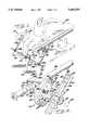
- FIG. 1is a side view in perspective of the apparatus during performance of an isokinetic assessment of a patient's limb in accordance with the present invention
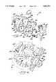
- FIG. 2is a side view in perspective, partially in phantom, of the pivot clamp shown in FIG. 1;
- FIG. 3is an exploded view of the pivot clamp shown in FIG. 2;
- FIG. 4is an end view of the pivot clamp shown in FIGS. 2 and 3;
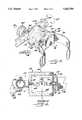
- FIG. 5is a side view in perspective of the limb engagement means shown in FIG. 1;
- FIG. 6is a side view in cross-section taken along line 6--6 of FIG. 5;
- FIG. 7is a side view in perspective of the apparatus during the performance of physical therapy in accordance with the present invention.
- FIG. 8is a perspective view of the limb engagement means showing the retaining strap securing a patient's limb during the performance of a isokinetic assessment of the limb in accordance with the present invention.
- the deviceincludes a pair of pivot clamps 10 which are capable of being attached to either a physical therapy table or the like, generally designated as AA, or to a solid object such as a wall, door or the like (not shown).
- the pivot clamps 10each cooperate with a plurality of frame members 12a-12c to form a rigid frame, generally designated as 14.
- the frame members 12a-12care conventional load or traction frame components which are readily available at most hospitals and physical therapy centers.
- a limb engaging member 16releasably connects at one end thereof to the rigid frame 14 and at its opposite end to a patient's limb to be measured.
- a force transducer, generally designated at 18,is connected to the limb engaging member 16 for detecting a force transmitted between the patient's limb and the limb engaging member.
- each of the pivot clamps 10includes a body portion 20 having a first end 22 which, in the embodiment shown, defines a first key-hole shaped opening 24 adapted to receive a slide bar 26 fastened to the physical therapy table AA.
- first end 22may be a mounting plate (not shown) to fixedly attach each of the pivot clamps 10 to the physical therapy table AA or a fixed object such as a wall.
- a second opening 28 in the body 20is oriented generally transverse to the first opening 24 for threadingly receiving an adjustable retaining screw 30.
- the retaining screw 30is then tightened to secure the pivot clamp 10 into position.
- a first plate 32is integrally formed with the body portion 20.
- the first plate 32has a generally circular configuration with a substantially smooth front face 31 and peripheral edge 33 and is oriented generally transverse to the longitudinal axis of the body portion 20.
- a plurality of first apertures 34are located along the peripheral edge 33 of the front face 31 of the first face plate 32.
- the plurality of first apertures 34are spaced apart in ten degree intervals around the entire first face plate 32. It is to be understood however that the intervals between the plurality of first apertures 34 may vary as desired.
- Centrally located in the first face plate 32 and extending generally transverse thereto,is a shaft 36 having a threaded free-end 37.
- a second end of the pivot clamp 10comprises a second face plate 38 having a substantially smooth front face 39.
- the second face plate 38includes a mounting collar 40.
- the mounting collar 40defines a bore 42 sized to receive the shaft 36.
- the collar 40is adapted to be seated on the shaft 36 enabling the threaded free end 37 of the shaft to project outward therefrom.
- the second face place 38has a generally rectangular configuration with a pair of opposed substantially smooth curved peripheral ends 41 which correspond in shape and size to the peripheral edge 33 of the first face plate 32.
- a plurality of second apertures 48are located along the curved peripheral edge of the second face plate 38.
- the second apertures 48may be spaced at a distance similar to that of the first apertures 34. Alternatively, it is possible to space the second apertures 48 a distance which is either greater or less than that of the first apertures 34.
- a tightening meanswhich in this embodiment is a wing nut handle 46 having an internal threaded bore 47 is then threaded onto the shaft 36 so as to selectively lock the second face plate 38 relative to the first face plate 32, once the second face plate 38 has been rotated to the desired position. It is to be understood that a wide variety of tightening means may be used, such as a nut or other conventional fastener and remain within the spirit of the invention.
- a release pinin this embodiment a quick release pin generally indicated at 50, is secured to the front face 39 of the second face plate 38 such that a pin portion 52 is received in a mounting aperture 53.
- the handle 54 of the quick release pin 50is movable between a first position (shown in phantom in FIG. 2) and a second position (shown in FIG. 4). In the first position, the handle 54 is in general longitudinal alignment with the pin portion 52, which causes the pin portion to be retracted toward the handle so that the pin portion does not project beyond the second face plate 38.
- the retraction of the pin portion 52 from the first apertures 34enables pivotal movement of the second face plate 38 relative to the first face plate 32 in the direction of arrow DD as shown in FIGS. 2, 4, and 7.
- the wing nut handle 46To allow the second face plate 38 to pivot in the first position, it is also necessary for the wing nut handle 46 to be loosened about the shaft 36.
- the mounting aperture 53aligns with one of the plurality of first apertures 34.
- the handle 54 of the quick release pin 50is then moved to the second position wherein the pin portion 52 projects or is inserted into the aligned first aperture 34 of the first face plate 32.
- the wing nut handle 46is then tightened in a generally clockwise direction to lock the second face plate 38 relative to the first face plate 32.
- the second apertures 48are located on either side of the mounting aperture 53 to assist in aligning the mounting aperture with one of the first apertures 34.
- the front face 39 of the second face plate 38also has a first adjustable bracket 56 secured thereto by conventional means such as a screw 57.
- the first adjustable bracket 56is adjustable by means of a bracket handle 58 which alternatively loosens and tightens the adjustable bracket so as to receive one of the first frame members 12a or 12b.
- the first adjustable bracket 56is adapted to receive the first frame member 12b.
- the rigid frame 14is formed from frame members 12a-12c having a generally octagonal cross-section which enables both rotational movement about the longitudinal axis of the respective first frame members 12a and 12b in the direction of arrow EE and translational movement of the respective frame members relative to the pivot clamp 10 in the direction of arrow FF shown in FIGS. 2 and 4 when the first adjustable bracket 56 is loose.
- the rigid frame 14may be pivoted horizontally relative to the physical therapy table AA.
- the second frame member 12cis also adjustably attached to the first frame members 12a and 12b by a pair of second adjustable brackets 59a and 59b.
- the second adjustable brackets 59a, 59ballow translational movement of the second frame member 12c relative to the pair of first frame members 12a, 12b in the direction of arrow GG to move it closer or further from the table AA and rotational movement of the second frame member about its longitudinal axis in the direction of arrow HH in FIG. 1.
- the rigid frame 14may be infinitely adjusted about any or all of the described three degrees freedom in order to position the limb engaging member 16 in the desired location and orientation relative to the patient's limb to be measured.
- the force transducer 18includes a housing 60 having a generally cylindrical configuration.
- the housing 60defines an internal cavity 62 for receiving therein a strain gauge 64 oriented so as to cooperate with the limb engaging member 16.
- the housing 60 of the force transducer 18is connected at one end thereof to a third adjustable bracket 66 having a configuration similar to the first and second adjustable brackets 56 and 59a, 59b.
- a third adjustable bracket handle 68enables the force transducer 18 to be connected to one of the first pair of frame members 12a and 12b or the second frame member 12c as well as enable rotational movement relative to the longitudinal axis of the respective frame member in this instance 12c in the direction of arrow JJ in FIGS. 5 and 6 and allow translational movement relative to the third adjustable bracket in the direction of arrow KK in FIG. 5.
- the limb engaging member 16is pivotally connected to the housing 60 by means of a mounting member 70.
- the mounting member 70as shown in FIGS. 5 and 8, is a generally rectangular plate having guides 72 located at opposed ends thereof for receiving a retaining strap 74.
- the retaining straphas a buckle and loop arrangement which allows the retaining step 74 to be releasably secured around a patient's leg to ensure that there is no play between the limb engaging member 16 and the patient's leg.
- retaining strap 74may be used as long as the retaining strap 74 easily opens and closes to alternatively release and secure a patient's leg and secondly has a fastening device which is sufficiently secure to retain the patient's leg to avoid any excessive movement between the patient's limb and the limb engaging member.
- the strain gauge 64is oriented along the longitudinal axis of the housing 60.
- the strain gauge 64is threadingly secured at one end thereof by a threaded bolt 73 extending outward therefrom, to the second adjustable bracket 66.
- the opposed end of the strain gauge 64is secured by a threaded nut and bolt, collectively referred to as 75, which allows pivotal movement of the mounting member 70 relative to the housing 60 in direction LL as shown in FIG. 5.
- This arrangementalso enables the strain gauge 64 to form a solid attachment between the frame member, in this embodiment, second frame member 12c, and the mounting member 70 of the limb engaging member 16, to ensure that any tensile or compression force exerted by the patient's limb is directly transferred to the strain gauge.
- the strain gauge 64 of the force transducer 18produces an output which is representative of the directed force applied by the patient's limb and transfers this output to a display 76.
- a digital panel metermay be used for displaying the output received from the force transducer 18 in digital form.
- a patientis positioned on the physical therapy table AA in a desired location, in this instance, sitting on the edge of the table with both legs hanging over the edge thereof.
- the rigid frame 14is then moved from a storage position (not shown).
- the retaining screw 30 of each of the pair of pivot clamps 10is loosened to enable translational movement BB of each of the pivot clamps along the slide rail 26 toward the end of the table AA adjacent the patient.
- the retaining screw 30 of each of the pivot clampsis tightened to prevent further sliding of the pivot clamps.
- the handle 54 of the quick release pin 50is then moved to the first position retracting pin portion 54 from the aligned first aperture 34 of the first face plate 32 and the wing nut handle 46 is then rotated in a counterclockwise direction to loosen the handle relative to the shaft 36 of the first face plate 32.
- each pivot clamptaking the rigid frame 14 with it, is then pivoted downward in the direction of arrow DD to the desired location, in this instance adjacent the floor, as shown in FIG. 1.
- the handle 54 of the quick release pin 50is moved to the second position causing the pin portion 52 to project passed the second face plate 38 and into the aligned aperture 34.
- the wing nut handle 46is then rotated in the clockwise direction to tighten down the second face plate 38 relative to the first face plate 34.
- the handle 58 of the first adjustable bracket 56is loosened to allow the first frame members 12a and 12b to translate longitudinally in the direction of arrow FF relative to the pivot clamp 10 and move second frame member 12c either closer to or further from the patient seated upon the physical therapy table AA.
- the handle 58is rotated in a clockwise direction to tighten the adjustable bracket 56 about the first frame members 12a and 12b once the desired location has been achieved. It is to be understood that adjustments about all the available degrees of freedom need not be made to position the rigid frame 14 in the desired position and orientation for each test. However, the ability to move the rigid frame and pivot clamps in such a multitude of degrees of freedom relative to the patient and the table greatly enhances the versatility of the device.
- the limb engaging member 18is then positioned laterally, i.e., undergoes translational movement, in the direction of arrow KK relative to and/or rotated about the second frame member 12c in the direction of arrow JJ by loosening the third adjustable bracket 66.
- the force transducer 18 and the limb engaging member 16should be positioned so as to properly align with the limb of the patient to be measured.
- the retaining strap 74 of the limb engaging member 16is then comfortably secured about the patient's limb to be measured.
- the patientUpon direction from the individual conducting the test, the patient either flexes or extends the limb to exert either a compression or tensile force, respectively against the limb engaging member 16.
- the pressure exerted by the patient against the limb engaging member 16is transferred to the force transducer 18.
- the measured force exerted by the patientis carried by a cable 80 to the output display device 76 where it is displayed in a desired form, in this case as a digital readout.
- Each of the pair of first frame members 12a, 12b, the second frame member 12c, the first face plate 32 and, when used, the slide rail 26have index markings 82 along a surface thereof to enable the pivot clamp 10, the limb engaging member 16, and the rigid frame 14 to be easily repeatably positioned in the same location for subsequent tests to ensure uniformity and reliability of such tests.
- FIG. 7An alternative embodiment of the device is shown in FIG. 7.
- the deviceis intended for use in exercising or conducting physical therapy of a patient's joint or limb. It is anticipated, that the device will be used with a patient on a physical therapy table or hospital bed designated AA'.
- the pivot clamps 10'are used with a rigid frame 14' similar to the one previously described.
- a variety of exercise equipmentmay be attached to the rigid frame by use of attachment means such as the third adjustable bracket described above.
- a second rigid frame 14"may be used in conjunction with the first rigid frame 14' to cooperatively receive a variety of exercise equipment such as the weight and sling shown generally at 78.
- the rigid frame 14' and the pivot clamps 10'are identical to those previously discussed in the context of the preferred embodiment shown in FIGS. 1-6 and 8. The ability of the pivot clamps 10' and the rigid frames 14' and 14" to selectively move about the numerous of degrees of freedom allows the rigid frame 14' to be adjusted in an infinite variety of positions with a wide variety of exercise equipment.
- first frame members 12a and 12b, and the second frame member 12cto form a generally rectangular rigid frame 14
Landscapes
- Health & Medical Sciences (AREA)
- Life Sciences & Earth Sciences (AREA)
- Physical Education & Sports Medicine (AREA)
- Orthopedic Medicine & Surgery (AREA)
- General Health & Medical Sciences (AREA)
- Heart & Thoracic Surgery (AREA)
- Engineering & Computer Science (AREA)
- Biomedical Technology (AREA)
- Pathology (AREA)
- Medical Informatics (AREA)
- Molecular Biology (AREA)
- Surgery (AREA)
- Animal Behavior & Ethology (AREA)
- Biophysics (AREA)
- Public Health (AREA)
- Veterinary Medicine (AREA)
- Physics & Mathematics (AREA)
- Accommodation For Nursing Or Treatment Tables (AREA)
Abstract
Description
Claims (32)
Priority Applications (1)
| Application Number | Priority Date | Filing Date | Title |
|---|---|---|---|
| US08/451,173US5662591A (en) | 1995-05-26 | 1995-05-26 | Apparatus for exercising and measuring strength of a patient's limb and an adjustable pivot clamp |
Applications Claiming Priority (1)
| Application Number | Priority Date | Filing Date | Title |
|---|---|---|---|
| US08/451,173US5662591A (en) | 1995-05-26 | 1995-05-26 | Apparatus for exercising and measuring strength of a patient's limb and an adjustable pivot clamp |
Publications (1)
| Publication Number | Publication Date |
|---|---|
| US5662591Atrue US5662591A (en) | 1997-09-02 |
Family
ID=23791097
Family Applications (1)
| Application Number | Title | Priority Date | Filing Date |
|---|---|---|---|
| US08/451,173Expired - LifetimeUS5662591A (en) | 1995-05-26 | 1995-05-26 | Apparatus for exercising and measuring strength of a patient's limb and an adjustable pivot clamp |
Country Status (1)
| Country | Link |
|---|---|
| US (1) | US5662591A (en) |
Cited By (33)
| Publication number | Priority date | Publication date | Assignee | Title |
|---|---|---|---|---|
| US6216293B1 (en) | 1999-04-20 | 2001-04-17 | Hill-Rom, Inc. | Fracture frame mounting apparatus |
| US6325767B1 (en)* | 1998-09-08 | 2001-12-04 | Hartmut Wolff | Strength measuring device for the measurement of muscle strength of singular muscle groups of an individual |
| US20030145381A1 (en)* | 2002-01-03 | 2003-08-07 | Higdon Kathryn A. | Support structure for use with patient support |
| US20030163871A1 (en)* | 2002-01-03 | 2003-09-04 | Conlu Alan Scott | Frame structure for use with patient support |
| US6622980B2 (en)* | 2000-03-28 | 2003-09-23 | Hill-Rom Services, Inc. | Socket and rail clamp apparatus |
| US20040255384A1 (en)* | 2003-06-17 | 2004-12-23 | Donald Chandler | Leg support apparatus |
| US20050223494A1 (en)* | 2004-02-20 | 2005-10-13 | Stm International | Medical equipment handling device |
| US20070037676A1 (en)* | 2005-08-15 | 2007-02-15 | Denisco Christopher R | Horizontal hamstring stretcher |
| US20070161475A1 (en)* | 2002-03-01 | 2007-07-12 | Kerrymagyari Llc | Abdominal exercise device for inverted abdominal exercises |
| US7303513B1 (en)* | 2004-01-02 | 2007-12-04 | Curtiss Gordon H | Therapeutic rehabilitative apparatus |
| US20090017995A1 (en)* | 2007-07-13 | 2009-01-15 | Freiberg Richard A | Knee manipulating device |
| US20100281666A1 (en)* | 2009-05-06 | 2010-11-11 | Lin-Yao Tseng | Assembling device for bed assembly |
| US20110143898A1 (en)* | 2009-12-14 | 2011-06-16 | Hill-Rom Services, Inc. | Patient support apparatuses with exercise functionalities |
| US20110263389A1 (en)* | 2008-07-24 | 2011-10-27 | Rinaldo Burgassi | Multifunctional training apparatus for the lower limb muscles |
| US8082786B1 (en)* | 2004-01-15 | 2011-12-27 | Robert Akins | Work capacities testing apparatus and method |
| US20120049035A1 (en)* | 2010-08-26 | 2012-03-01 | Equipois, Inc. | Multi-arm gimbal system |
| WO2014032072A1 (en) | 2012-09-03 | 2014-03-06 | Queensland University Of Technology | Apparatus and method for knee flexor assessment |
| WO2014078667A1 (en)* | 2012-11-16 | 2014-05-22 | Hill-Rom Services, Inc. | Person support apparatuses having exercise therapy features |
| US8752428B2 (en) | 2004-01-15 | 2014-06-17 | Robert Akins | Work capacities testing apparatus and method |
| US8756735B2 (en) | 2011-02-08 | 2014-06-24 | Hill-Rom Services, Inc. | Patient helper with egress handle |
| US9028433B2 (en) | 2012-04-26 | 2015-05-12 | University Of New Brunswick | Limb strength measurement device |
| US9038218B1 (en) | 2014-01-15 | 2015-05-26 | Hill-Rom Services, Inc. | Person support apparatuses with selectively coupled foot sections |
| US9132051B2 (en) | 2014-01-15 | 2015-09-15 | Hill-Rom Services, Inc. | Person support apparatuses with exercise functionalities |
| CN106691002A (en)* | 2016-12-27 | 2017-05-24 | 贺州思通信息技术有限公司 | Multifunctional bed |
| CN109045596A (en)* | 2018-07-24 | 2018-12-21 | 北京大学深圳医院 | rehabilitation exercise device |
| US10206305B2 (en)* | 2016-02-23 | 2019-02-12 | Nec Platforms, Ltd. | Support device and support method |
| US10393163B2 (en)* | 2015-03-24 | 2019-08-27 | Basi Systems Pilates Sanayi Ticaret A.S. | Mechanism for height and distance adjustment in pilates exercise equipment |
| WO2020095251A1 (en)* | 2018-11-07 | 2020-05-14 | Force Hooks Pty Ltd | Apparatus for measuring isometric muscle strength |
| US10729369B2 (en) | 2017-06-23 | 2020-08-04 | Kangatech Pty Ltd. | Testing and training apparatus |
| US10799170B1 (en) | 2019-02-11 | 2020-10-13 | U.S. Government As Represented By The Secretary Of The Army | Apparatus for measuring isometric muscle strength |
| US10874567B2 (en) | 2014-03-11 | 2020-12-29 | Hill-Rom Services, Inc. | Patient bed having footboard pedal apparatus for physical therapy |
| US20230081926A1 (en)* | 2021-09-10 | 2023-03-16 | Cheng Cheng CHANG | Mountable Arm Assembly for Fitness Equipment |
| US11963918B2 (en) | 2020-04-20 | 2024-04-23 | Hill-Rom Services, Inc. | Patient bed having active motion exercise |
Citations (24)
| Publication number | Priority date | Publication date | Assignee | Title |
|---|---|---|---|---|
| US1398092A (en)* | 1920-09-10 | 1921-11-22 | Linotype Machinery Ltd | Keyboard mechanism of typographical composing and other keycontrolled machines |
| US1792612A (en)* | 1928-07-13 | 1931-02-17 | Joseph H Staley | Airplane-engine stand |
| US2340572A (en)* | 1942-09-16 | 1944-02-01 | W L Grill | Clamp and supporting bar for drills |
| US2446470A (en)* | 1946-03-15 | 1948-08-03 | Roger H Godwin | Adjustable clamp |
| US2855199A (en)* | 1955-11-09 | 1958-10-07 | N K Products Company | Exercise device |
| US3120954A (en)* | 1961-01-09 | 1964-02-11 | Chris J Apostol | Muscle exercising apparatus |
| US3285070A (en)* | 1963-06-26 | 1966-11-15 | Elgin Elmac Entpr Inc | Muscular evaluation and exercising apparatus |
| US3339913A (en)* | 1963-10-08 | 1967-09-05 | Ritter Pfaudler Corp | Accessory clamping structure for surgical tables |
| US3374675A (en)* | 1965-01-04 | 1968-03-26 | Keropian Michael | Isometric muscle testing apparatus |
| US3612042A (en)* | 1970-01-13 | 1971-10-12 | Louis R Fry | Hip exerciser |
| US3904195A (en)* | 1973-09-07 | 1975-09-09 | Rene Chavanne | Body exercising and re-education apparatus |
| US3970274A (en)* | 1974-10-30 | 1976-07-20 | Resk E Edward | Tilt mounting |
| US4307608A (en)* | 1977-12-12 | 1981-12-29 | Fitness Motivation Institute Of America | Apparatus for digitally displaying muscle strength |
| US4368957A (en)* | 1980-10-31 | 1983-01-18 | Discovision Associates | Wide aperture objective lens |
| US4549555A (en)* | 1984-02-17 | 1985-10-29 | Orthothronics Limited Partnership | Knee laxity evaluator and motion module/digitizer arrangement |
| US4551872A (en)* | 1984-02-06 | 1985-11-12 | Professional Medical Products, Inc. | Orthopedic traction frame |
| US4602618A (en)* | 1984-12-31 | 1986-07-29 | Berze Robert W | Continuous hip-joint motion machine |
| US4763897A (en)* | 1986-09-05 | 1988-08-16 | Yakata Brian T | Exercise machine with adjustably positioned bar |
| US4772015A (en)* | 1987-04-23 | 1988-09-20 | The Toro Company | Shoulder and arm exercise machine |
| US4930523A (en)* | 1989-04-13 | 1990-06-05 | Lincoln Mills, Inc. | Surgical shoulder positioning apparatus |
| US5078152A (en)* | 1985-06-23 | 1992-01-07 | Loredan Biomedical, Inc. | Method for diagnosis and/or training of proprioceptor feedback capabilities in a muscle and joint system of a human patient |
| US5090421A (en)* | 1986-12-09 | 1992-02-25 | Hoggan Health Industries, Inc. | Apparatus for testing muscle strength |
| US5265589A (en)* | 1993-01-13 | 1993-11-30 | Wang Yuen Fu | Multiple-rehabilitation-equipment supporter |
| US5476241A (en)* | 1993-11-12 | 1995-12-19 | David L. Helman | Wheelchair accessory stand |
- 1995
- 1995-05-26USUS08/451,173patent/US5662591A/ennot_activeExpired - Lifetime
Patent Citations (24)
| Publication number | Priority date | Publication date | Assignee | Title |
|---|---|---|---|---|
| US1398092A (en)* | 1920-09-10 | 1921-11-22 | Linotype Machinery Ltd | Keyboard mechanism of typographical composing and other keycontrolled machines |
| US1792612A (en)* | 1928-07-13 | 1931-02-17 | Joseph H Staley | Airplane-engine stand |
| US2340572A (en)* | 1942-09-16 | 1944-02-01 | W L Grill | Clamp and supporting bar for drills |
| US2446470A (en)* | 1946-03-15 | 1948-08-03 | Roger H Godwin | Adjustable clamp |
| US2855199A (en)* | 1955-11-09 | 1958-10-07 | N K Products Company | Exercise device |
| US3120954A (en)* | 1961-01-09 | 1964-02-11 | Chris J Apostol | Muscle exercising apparatus |
| US3285070A (en)* | 1963-06-26 | 1966-11-15 | Elgin Elmac Entpr Inc | Muscular evaluation and exercising apparatus |
| US3339913A (en)* | 1963-10-08 | 1967-09-05 | Ritter Pfaudler Corp | Accessory clamping structure for surgical tables |
| US3374675A (en)* | 1965-01-04 | 1968-03-26 | Keropian Michael | Isometric muscle testing apparatus |
| US3612042A (en)* | 1970-01-13 | 1971-10-12 | Louis R Fry | Hip exerciser |
| US3904195A (en)* | 1973-09-07 | 1975-09-09 | Rene Chavanne | Body exercising and re-education apparatus |
| US3970274A (en)* | 1974-10-30 | 1976-07-20 | Resk E Edward | Tilt mounting |
| US4307608A (en)* | 1977-12-12 | 1981-12-29 | Fitness Motivation Institute Of America | Apparatus for digitally displaying muscle strength |
| US4368957A (en)* | 1980-10-31 | 1983-01-18 | Discovision Associates | Wide aperture objective lens |
| US4551872A (en)* | 1984-02-06 | 1985-11-12 | Professional Medical Products, Inc. | Orthopedic traction frame |
| US4549555A (en)* | 1984-02-17 | 1985-10-29 | Orthothronics Limited Partnership | Knee laxity evaluator and motion module/digitizer arrangement |
| US4602618A (en)* | 1984-12-31 | 1986-07-29 | Berze Robert W | Continuous hip-joint motion machine |
| US5078152A (en)* | 1985-06-23 | 1992-01-07 | Loredan Biomedical, Inc. | Method for diagnosis and/or training of proprioceptor feedback capabilities in a muscle and joint system of a human patient |
| US4763897A (en)* | 1986-09-05 | 1988-08-16 | Yakata Brian T | Exercise machine with adjustably positioned bar |
| US5090421A (en)* | 1986-12-09 | 1992-02-25 | Hoggan Health Industries, Inc. | Apparatus for testing muscle strength |
| US4772015A (en)* | 1987-04-23 | 1988-09-20 | The Toro Company | Shoulder and arm exercise machine |
| US4930523A (en)* | 1989-04-13 | 1990-06-05 | Lincoln Mills, Inc. | Surgical shoulder positioning apparatus |
| US5265589A (en)* | 1993-01-13 | 1993-11-30 | Wang Yuen Fu | Multiple-rehabilitation-equipment supporter |
| US5476241A (en)* | 1993-11-12 | 1995-12-19 | David L. Helman | Wheelchair accessory stand |
Non-Patent Citations (4)
| Title |
|---|
| A Static Dynamometer Measuring Multidirectional Torques Exerted Simultaneously at the Hip and Knee, D. Bourbonnais et al., J. Biomechanics, vol. 26, No. 3, pp. 277 283, 1993.* |
| A Static Dynamometer Measuring Multidirectional Torques Exerted Simultaneously at the Hip and Knee, D. Bourbonnais et al., J. Biomechanics, vol. 26, No. 3, pp. 277-283, 1993. |
| Knee Extension Torque in Stroke Patients: Comparison of Measurements Obtained With a Hand Held and a Cybex Dynamometer, R. W. Bohannon, Physiotherapy Canada, Nov./Dec., vol. 42, No. 6, pp. 284 287.* |
| Knee Extension Torque in Stroke Patients: Comparison of Measurements Obtained With a Hand-Held and a Cybex Dynamometer, R. W. Bohannon, Physiotherapy Canada, Nov./Dec., vol. 42, No. 6, pp. 284-287. |
Cited By (56)
| Publication number | Priority date | Publication date | Assignee | Title |
|---|---|---|---|---|
| US6325767B1 (en)* | 1998-09-08 | 2001-12-04 | Hartmut Wolff | Strength measuring device for the measurement of muscle strength of singular muscle groups of an individual |
| US6581897B2 (en) | 1999-04-20 | 2003-06-24 | Hill-Rom Services, Inc. | Fracture frame mounting apparatus, bracket, and method |
| US6216293B1 (en) | 1999-04-20 | 2001-04-17 | Hill-Rom, Inc. | Fracture frame mounting apparatus |
| US6622980B2 (en)* | 2000-03-28 | 2003-09-23 | Hill-Rom Services, Inc. | Socket and rail clamp apparatus |
| US20030145381A1 (en)* | 2002-01-03 | 2003-08-07 | Higdon Kathryn A. | Support structure for use with patient support |
| US20030163871A1 (en)* | 2002-01-03 | 2003-09-04 | Conlu Alan Scott | Frame structure for use with patient support |
| US20070161475A1 (en)* | 2002-03-01 | 2007-07-12 | Kerrymagyari Llc | Abdominal exercise device for inverted abdominal exercises |
| US7608031B2 (en) | 2002-03-01 | 2009-10-27 | Kerrymagyari Llc | Abdominal exercise device for inverted abdominal exercises |
| US6874184B2 (en)* | 2003-06-17 | 2005-04-05 | Donald Chandler | Leg support apparatus |
| US20040255384A1 (en)* | 2003-06-17 | 2004-12-23 | Donald Chandler | Leg support apparatus |
| US7303513B1 (en)* | 2004-01-02 | 2007-12-04 | Curtiss Gordon H | Therapeutic rehabilitative apparatus |
| US8082786B1 (en)* | 2004-01-15 | 2011-12-27 | Robert Akins | Work capacities testing apparatus and method |
| US9439594B2 (en) | 2004-01-15 | 2016-09-13 | Robert Akins | Work capacities testing apparatus and method |
| US8752428B2 (en) | 2004-01-15 | 2014-06-17 | Robert Akins | Work capacities testing apparatus and method |
| US20050223494A1 (en)* | 2004-02-20 | 2005-10-13 | Stm International | Medical equipment handling device |
| US7476182B2 (en)* | 2005-08-15 | 2009-01-13 | Denisco Christopher R | Horizontal hamstring stretcher |
| US20070037676A1 (en)* | 2005-08-15 | 2007-02-15 | Denisco Christopher R | Horizontal hamstring stretcher |
| US20090017995A1 (en)* | 2007-07-13 | 2009-01-15 | Freiberg Richard A | Knee manipulating device |
| US20110263389A1 (en)* | 2008-07-24 | 2011-10-27 | Rinaldo Burgassi | Multifunctional training apparatus for the lower limb muscles |
| US20100281666A1 (en)* | 2009-05-06 | 2010-11-11 | Lin-Yao Tseng | Assembling device for bed assembly |
| US20110143898A1 (en)* | 2009-12-14 | 2011-06-16 | Hill-Rom Services, Inc. | Patient support apparatuses with exercise functionalities |
| US8858409B2 (en) | 2009-12-14 | 2014-10-14 | Hill-Rom Services, Inc. | Patient support apparatuses with exercise functionalities |
| US9125785B2 (en) | 2009-12-14 | 2015-09-08 | Hill-Rom Services, Inc. | Patient support apparatuses with exercise functionalities |
| US20120049035A1 (en)* | 2010-08-26 | 2012-03-01 | Equipois, Inc. | Multi-arm gimbal system |
| US9534730B2 (en)* | 2010-08-26 | 2017-01-03 | Garrett W. Brown | Multi-arm gimbal system |
| US9585804B2 (en) | 2011-02-08 | 2017-03-07 | Hill-Rom Services, Inc. | Accessory frame attachment apparatus |
| US8756735B2 (en) | 2011-02-08 | 2014-06-24 | Hill-Rom Services, Inc. | Patient helper with egress handle |
| US9028433B2 (en) | 2012-04-26 | 2015-05-12 | University Of New Brunswick | Limb strength measurement device |
| CN104768462A (en)* | 2012-09-03 | 2015-07-08 | 昆士兰科技大学 | Device and method for knee flexor assessment |
| RU2626872C2 (en)* | 2012-09-03 | 2017-08-02 | Квинсленд Юниверсити Оф Текнолоджи | Device and method for knee flexor evaluation |
| US20150297128A1 (en)* | 2012-09-03 | 2015-10-22 | Queensland University Of Technology | Apparatus and method for knee flexor assessment |
| US11850050B2 (en)* | 2012-09-03 | 2023-12-26 | Queensland Univserity Of Technology | Apparatus and method for knee flexor assessment |
| EP2892430B1 (en) | 2012-09-03 | 2018-08-08 | Queensland University Of Technology | Apparatus and method for knee flexor assessment |
| WO2014032072A1 (en) | 2012-09-03 | 2014-03-06 | Queensland University Of Technology | Apparatus and method for knee flexor assessment |
| CN104768462B (en)* | 2012-09-03 | 2018-08-03 | 昆士兰科技大学 | Device and method for knee flexor assessment |
| WO2014078667A1 (en)* | 2012-11-16 | 2014-05-22 | Hill-Rom Services, Inc. | Person support apparatuses having exercise therapy features |
| US9687401B2 (en) | 2012-11-16 | 2017-06-27 | Hill-Rom Services, Inc. | Person support apparatuses having exercise therapy features |
| EP3653271B1 (en)* | 2012-11-16 | 2025-09-17 | Hill-Rom Services, Inc. | Person support apparatuses having exercise therapy features |
| US9038218B1 (en) | 2014-01-15 | 2015-05-26 | Hill-Rom Services, Inc. | Person support apparatuses with selectively coupled foot sections |
| US11452650B2 (en) | 2014-01-15 | 2022-09-27 | Hill-Rom Services, Inc. | Person support apparatuses with selectively coupled foot sections |
| US9132051B2 (en) | 2014-01-15 | 2015-09-15 | Hill-Rom Services, Inc. | Person support apparatuses with exercise functionalities |
| US10646389B2 (en) | 2014-01-15 | 2020-05-12 | Liko Research & Development Ab | Person support apparatuses with selectively coupled foot sections |
| US10874567B2 (en) | 2014-03-11 | 2020-12-29 | Hill-Rom Services, Inc. | Patient bed having footboard pedal apparatus for physical therapy |
| US10393163B2 (en)* | 2015-03-24 | 2019-08-27 | Basi Systems Pilates Sanayi Ticaret A.S. | Mechanism for height and distance adjustment in pilates exercise equipment |
| US10206305B2 (en)* | 2016-02-23 | 2019-02-12 | Nec Platforms, Ltd. | Support device and support method |
| CN106691002A (en)* | 2016-12-27 | 2017-05-24 | 贺州思通信息技术有限公司 | Multifunctional bed |
| US10729369B2 (en) | 2017-06-23 | 2020-08-04 | Kangatech Pty Ltd. | Testing and training apparatus |
| US11241180B2 (en) | 2017-06-23 | 2022-02-08 | Kangatech Pty Ltd. | Testing and training apparatus |
| CN109045596B (en)* | 2018-07-24 | 2023-09-15 | 北京大学深圳医院 | Rehabilitation exercise device |
| CN109045596A (en)* | 2018-07-24 | 2018-12-21 | 北京大学深圳医院 | rehabilitation exercise device |
| WO2020095251A1 (en)* | 2018-11-07 | 2020-05-14 | Force Hooks Pty Ltd | Apparatus for measuring isometric muscle strength |
| US10799170B1 (en) | 2019-02-11 | 2020-10-13 | U.S. Government As Represented By The Secretary Of The Army | Apparatus for measuring isometric muscle strength |
| US11963918B2 (en) | 2020-04-20 | 2024-04-23 | Hill-Rom Services, Inc. | Patient bed having active motion exercise |
| US12186248B2 (en) | 2020-04-20 | 2025-01-07 | Hill-Rom Services, Inc. | Patient bed having active motion exercise |
| US20230081926A1 (en)* | 2021-09-10 | 2023-03-16 | Cheng Cheng CHANG | Mountable Arm Assembly for Fitness Equipment |
| US11938367B2 (en)* | 2021-09-10 | 2024-03-26 | Global Solution International Co., Ltd. | Mountable arm assembly for fitness equipment |
Similar Documents
| Publication | Publication Date | Title |
|---|---|---|
| US5662591A (en) | Apparatus for exercising and measuring strength of a patient's limb and an adjustable pivot clamp | |
| US5324247A (en) | Apparatus and method for multi-axial spinal testing and rehabilitation | |
| US6227047B1 (en) | Strength evaluation isometric testing system | |
| AU2012388708B2 (en) | Apparatus and method for knee flexor assessment | |
| US4824103A (en) | Muscle Testing and exercising apparatus | |
| US4768779A (en) | Back exercise apparatus with a neck exercise attachment | |
| US8147386B2 (en) | Integral treadmill resistance training apparatus | |
| US4565368A (en) | Isokinetic exercise and monitoring machine | |
| US5094249A (en) | Apparatus for monitoring the motion of the lumbar spine | |
| US5335674A (en) | Apparatus and method for determining load-displacement and flexibility characteristics of a joint | |
| US5360383A (en) | Apparatus and method for testing and exercising cevical muscles | |
| US4909262A (en) | Apparatus for obtaining a body limb torque signal | |
| JPH02289234A (en) | Measuring implement for measuring variation of tensile applied to implant ligament and measuring method therefor | |
| CN210278131U (en) | Isometric flexion and extension strength exercise and testing device for knee joint | |
| US4845987A (en) | Cervical muscle exercising and testing apparatus | |
| US6672157B2 (en) | Power tester | |
| US5471996A (en) | Apparatus and method for measuring abduction strength of a patient's thumb | |
| CA2857693C (en) | Limb strength measurement device | |
| Tsiros et al. | The Biodex isokinetic dynamometer for knee strength assessment in children: advantages and limitations | |
| JP2019523688A (en) | Device for measuring, diagnosing and / or treating human finger, hand, arm and / or shoulder forces | |
| US5487395A (en) | Apparatus for supporting an arm | |
| Garner et al. | Isometric shoulder girdle strength of healthy young adults | |
| CN210931470U (en) | A core muscle group strength test device | |
| JPH0115369Y2 (en) | ||
| US6572567B1 (en) | Mobile lift system and method of use |
Legal Events
| Date | Code | Title | Description |
|---|---|---|---|
| AS | Assignment | Owner name:JOHNS HOPKINS UNIVERSITY, THE, MARYLAND Free format text:ASSIGNMENT OF ASSIGNORS INTEREST;ASSIGNORS:MCCARTHY, MELISSA LEE;MACKENZIE, ELLEN JANE;REEL/FRAME:007573/0203 Effective date:19950719 Owner name:CHARLOTTE-MECKLENBURG HOSPITAL AUTHORITY, THE, NOR Free format text:ASSIGNMENT OF ASSIGNORS INTEREST;ASSIGNOR:PEINDL, RICHARD D.;REEL/FRAME:007573/0172 Effective date:19950717 | |
| AS | Assignment | Owner name:NATIONAL INSTITUTES OF HEALTH, THE, MARYLAND Free format text:CONFIRMATORY LICENSE;ASSIGNOR:JOHNS HOPKINS UNIVERSITY, THE;REEL/FRAME:009093/0315 Effective date:19980305 | |
| STCF | Information on status: patent grant | Free format text:PATENTED CASE | |
| CC | Certificate of correction | ||
| FPAY | Fee payment | Year of fee payment:4 | |
| FPAY | Fee payment | Year of fee payment:8 | |
| AS | Assignment | Owner name:NATIONAL INSTITUTES OF HEALTH (NIH), U.S. DEPT. OF Free format text:CONFIRMATORY LICENSE;ASSIGNOR:JOHNS HOPKINS UNIVERSITY;REEL/FRAME:021600/0280 Effective date:19980305 | |
| FPAY | Fee payment | Year of fee payment:12 |