US5662105A - System and method for the extractment of physiological signals - Google Patents
System and method for the extractment of physiological signalsDownload PDFInfo
- Publication number
- US5662105A US5662105AUS08/442,834US44283495AUS5662105AUS 5662105 AUS5662105 AUS 5662105AUS 44283495 AUS44283495 AUS 44283495AUS 5662105 AUS5662105 AUS 5662105A
- Authority
- US
- United States
- Prior art keywords
- signal
- ratio
- generated signal
- peak
- value
- Prior art date
- Legal status (The legal status is an assumption and is not a legal conclusion. Google has not performed a legal analysis and makes no representation as to the accuracy of the status listed.)
- Expired - Lifetime
Links
Images


Classifications
- A—HUMAN NECESSITIES
- A61—MEDICAL OR VETERINARY SCIENCE; HYGIENE
- A61B—DIAGNOSIS; SURGERY; IDENTIFICATION
- A61B5/00—Measuring for diagnostic purposes; Identification of persons
- A61B5/145—Measuring characteristics of blood in vivo, e.g. gas concentration or pH-value ; Measuring characteristics of body fluids or tissues, e.g. interstitial fluid or cerebral tissue
- A61B5/1455—Measuring characteristics of blood in vivo, e.g. gas concentration or pH-value ; Measuring characteristics of body fluids or tissues, e.g. interstitial fluid or cerebral tissue using optical sensors, e.g. spectral photometrical oximeters
- A61B5/14551—Measuring characteristics of blood in vivo, e.g. gas concentration or pH-value ; Measuring characteristics of body fluids or tissues, e.g. interstitial fluid or cerebral tissue using optical sensors, e.g. spectral photometrical oximeters for measuring blood gases
- A—HUMAN NECESSITIES
- A61—MEDICAL OR VETERINARY SCIENCE; HYGIENE
- A61B—DIAGNOSIS; SURGERY; IDENTIFICATION
- A61B5/00—Measuring for diagnostic purposes; Identification of persons
- A61B5/72—Signal processing specially adapted for physiological signals or for diagnostic purposes
- A61B5/7203—Signal processing specially adapted for physiological signals or for diagnostic purposes for noise prevention, reduction or removal
- A61B5/7207—Signal processing specially adapted for physiological signals or for diagnostic purposes for noise prevention, reduction or removal of noise induced by motion artifacts
- A—HUMAN NECESSITIES
- A61—MEDICAL OR VETERINARY SCIENCE; HYGIENE
- A61B—DIAGNOSIS; SURGERY; IDENTIFICATION
- A61B5/00—Measuring for diagnostic purposes; Identification of persons
- A61B5/72—Signal processing specially adapted for physiological signals or for diagnostic purposes
- A61B5/7235—Details of waveform analysis
- A61B5/725—Details of waveform analysis using specific filters therefor, e.g. Kalman or adaptive filters
- A—HUMAN NECESSITIES
- A61—MEDICAL OR VETERINARY SCIENCE; HYGIENE
- A61B—DIAGNOSIS; SURGERY; IDENTIFICATION
- A61B5/00—Measuring for diagnostic purposes; Identification of persons
- A61B5/72—Signal processing specially adapted for physiological signals or for diagnostic purposes
- A61B5/7235—Details of waveform analysis
- A61B5/7239—Details of waveform analysis using differentiation including higher order derivatives
Definitions
- the present inventionrelates generally to signal processing and, more particularly, to a system and method for processing physiological signals in the presence of noise to extract the physiological signals.
- ECGelectrocardiogram
- the signalsare based on the electrical activity generated by the electrical depolarization of the heart muscle.
- the signalsare typically detected by surface electrodes mounted on the chest of the patient.
- the signalsare initially weak at the signal source (i.e., the heart) and are even weaker at the surface of the chest.
- electrical interference from the activity of other muscles, noise caused by patient breathing, general movement, and the likecause additional interference with the ECG signal.
- External electrical interferencesuch as 60 Hertz (Hz) interference also compounds the ECG measurement problem. Therefore, great care must be taken in the design and use of physiological processors to enhance the quality of the desired signal and reduce the effects of interfering signals.
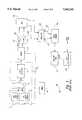
- a transmissive pulse oximetry sensor 2is placed on a finger 4 of the patient.
- First and second light sources 6 and 8are directed through the fleshy portion of the finger 4 and detected by one or more light detectors 10 on the opposite side of the finger.
- the light from light sources 6 and 8are of different wavelengths that are differentially absorbed by oxygenated blood cells.
- the first light source 6is typically designated as a Red light source having a wavelength in the red region of the spectrum.
- the second light source 8is typically designated the IR source having a wavelength in the near infrared region of the spectrum.
- the pulse oximeter 1determines the oxygen saturation based on a ratio of the light detected from the Red light source 6 and the IR light source 8, respectively.
- a ratio calculator 12determines the ratio of detected light and uses the value of the ratio as an address in a look-up table 14.
- the look-up table 14contains data relating the ratio of detected light to the oxygen saturation in the blood.
- a typical oxygen saturation curve 18is illustrated in FIG. 2 where the percentage of oxygen saturation is plotted against the ratio of detected light from the Red light source 6 and the IR light source 8 (see FIG. 1).
- Pulse oximetersmay also use reflective pulse oximetry sensors (not shown) in which the light sources and light detectors are positioned adjacent each other, and the light from the light sources is reflected back to the detector(s) by oxygenated blood cells in the finger 4.
- pulse oximetry measurementalso is susceptible to interference form noise.
- pulse oximetryis particularly susceptible to interference from stray light and from patient motion. Stray light detected by the light detector 10 can cause erroneous calculation of the ratio. Known techniques are employed to reduce the interference caused by stray light. The interference from patient motion is a much more difficult noise source and is the subject of intensive research.
- the present inventionis embodied in a system and method for the enhancement of signals in the presence of noise.
- the systemincludes a detector to detect first and second signals, each of the detected signals having a signal portion and an interference portion.
- the systemincludes an adaptive signal processor having a signal input, an adaptive filter input, an adaptive filter output, and an error signal output wherein the error signal output is coupled to the adaptive filter to adjust the adaptive filter such that the error signal has minimum correlation with the filter input.
- the signal input of the adaptive filteris coupled to the detector to receive the first detected signal.
- a peak detectorreceives a signal from the adaptive signal processor and determines a ratio constant corresponding to a peak value of the signal from the adaptive signal processor over a predetermined range of possible ratios.
- a storage locationcontains a mathematical relationship of the first and second portions of the first and second detected signals and a ratio constant.
- a reference signal generatorcoupled to the peak detector and to the storage location generates the signal portion of the first detected signal based on the mathematical relationship and the ratio constant.
- the signal portion of the first detected signalmay be coupled to the filter input to permit the adaptive filter to generate a filtered version of the first portion of the first detected signal.
- the signal from the adaptive signal processor and received by the peak detectormay be the error signal output or the adaptive filter output.
- the peak detectorsubdivides the predetermined range into first and second substantially equal ranges and determines peak location in either the first or second ranges.
- the peak detectorcontinues to subdivide the range containing the peak until the peak detector determines the first ratio constant corresponding to the peak location. This technique advantageously permits the peak detector to quickly locate a peak without the necessity of scanning the entire range of ratio values.
- the reference signal generatoruses the mathematical relationship and the first ratio constant to generate the signal portion of the second detected signal.
- the signal portion of the second detected signalmay be applied to the filter input as a second reference signal. This permits the adaptive filter to generate a filtered version of the first portion of the second detected signal.
- signal inputs of first and second adaptive signal processorsreceive the first and second detected signals, respectively.
- First and second reference signalsare generated and coupled to the adaptive filter inputs of the first and second adaptive signal processors, respectively.
- the filter outputs of the first and second adaptive filtersare coupled to a ratio processor, which generates a ratio output indicative of the difference between ratio constants in the first and second reference signals, and desired values of the ratio constants. The ratio output is at a minimum when the selected ratio constants in the first and second reference signals are equal to the desired ratio constants.
- the systemis used to extract physiological signals for the measurement of blood oxygen in a subject.
- the systemincludes first and second light sources to direct light of different wave length toward the subject.
- a light detectoris positioned to detect the first and second lights after passage through the subject, with each of the detected light signals having first and second portions.
- the light detectorgenerates signals indicative of an intensity of the first and second detected light signals.
- the first portion of the detected light signalarises from the light transmitted from the light source, and the second portion of the detected signal arises from interference source.
- the adaptive signal processorhas a signal input coupled to the light detector and the reference input coupled to a reference signal generator.
- the reference signal generatoruses the mathematical relationship of the first and second detected signals and ratio constants to generate the reference signal.
- a peak detectoris used to determine correct values of the first and second ratio constants, such that the reference signal is indicative of the first portion of the detected signal, and the output of the adaptive filter is a wave form representing the true intensity of light transmitted through the subject.
- FIG. 1is a functional block diagram of a prior art oximetry system.
- FIG. 2is a typical oxygen saturation curve employed by the system of FIG. 1 to determine blood oxygen saturation.
- FIG. 3is a functional block diagram of a conventional adaptive signal processor.
- FIG. 4is a detailed functional block diagram of the system of FIG. 1.
- FIG. 5are waveforms that illustrate the timing control of light sources used by the system of FIG. 4.
- FIG. 6illustrates a waveform used in the calculation of a reference noise signal by the conventional adaptive signal processor of FIG. 3.
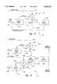
- FIG. 7is a functional block diagram of the present invention used with the system of FIG. 4.
- FIG. 8illustrates a first embodiment of the system of FIG. 7.
- FIG. 9illustrates a waveform used in the calculation of a reference signal by the analyzer of FIG. 8.
- FIG. 10is a functional block diagram of the peak detector of FIG. 8.
- FIGS. 11A and 11Bare flowcharts of the operation of the peak detector of the system of FIG. 10.
- FIG. 12is a functional block diagram of an alternative embodiment of the analyzer of FIG. 7.
- FIG. 13is a functional block diagram of another alternative embodiment of the analyzer of FIG. 7.
- Measurement of physiological signals in the presence of interferenceis a difficult task, particularly if the interference is somewhat random rather than periodic.
- a number of different techniquescan potentially be used to separate the desired physiological signal from the interfering noise signal.
- a filtercan sometimes be used to remove the interfering noise signal.
- Notch filterssuch as a 60 Hz notch filter, can be used to minimize interference from line noise.
- high frequency interference noise signalscan be eliminated with a lowpass filter designed to pass the physiological signal of interest and to reject frequencies above the physiological signal bandwidth.
- some interference sourceshave the same or similar frequency content as the physiological signal of interest. For interference of this type, different signal processing technologies must be employed.
- Adaptive signal processingis one well known technique for the separation of a desired signal from an interference signal. Adaptive signal processing is based on the assumption that the noise caused by the interference signal is uncorrelated to the desired signal.
- a conventional adaptive signal processorconfigured as a correlation canceller, is illustrated in the functional block diagram of FIG. 3.
- An adaptive processor 20has a signal input 22 and a reference input 24. The reference input 24 is fed to an adaptive filter 28.
- the adaptive filter 28generates a filter output 30 that is subtracted from the signal input 22 in a conventional subtractor 34.
- the subtractor 34generates an error signal 38 that is fed back to the adaptive filter 28.
- the error signal 38has a value designated herein as ⁇ .
- the adaptive filter 28is automatically adjusted so that the error signal 38 has a minimum correlation with the reference input 24.
- the adaptive filter 28is adjusted so that the subtractor 34 cancels any correlated signal in the signal input 22.
- the error signal 38is the system output and contains the portion of the input signal 22 that is uncorrelated to the reference input 24.
- the signal input 22consists of a combination of a pure input signal from a device, such as a sensor, and a noise signal from one or more sources.
- the reference input 24should then be a signal that is related to and at least partially correlated with, the noise signal.
- the adaptive filter 28is adjusted so that the error signal 38 is the pure input signal since the pure input signal has a minimum correlation with the reference signal applied to the reference input 24.
- Adaptive signal processinghas been successfully applied to the measurement of physiological signals when the source of the interference signal is well characterized.
- the physicianmay wish to listen to a fetal heartbeat whose acoustical signal strength is relatively small compared to the acoustical strength of the mother's heartbeat.
- simple filteringwill not work satisfactorily because the two heartbeats have similar frequency content.
- adaptive signal processingcan isolate the fetal heartbeat by using the much louder maternal heartbeat as the reference input 24 and the combination of fetal and mammal heartbeats as the signal input 22. Because the two heartbeats are uncorrelated and the maternal heartbeat can be independently derived, the adaptive signal processor 20 can easily isolate the fetal heartbeat. Similarly, the adaptive signal processor 20 can remove 60 Hz interference by simply using the 60 Hz signal as the reference input 24. Thus, adaptive signal processing can effectively remove the undesirable interference signal provided that the interference signal can be independently derived.
- pulse oximetryis susceptible to motion artifact, as described above.
- the motionalters the path that the light takes through the finger 4 (see FIG. 1) and the characteristics of the interface between the finger 4 and the sensor 2.
- the light from the Red light source 6 and the IR light source 8pass through the fleshy portion of the finger 4, each is contaminated by a noise signal, primarily due to patient motion.
- the detected lightis thus the combination of the true light transmitted through the finger 4 plus the interfering noise introduced in the measurement process. This may be illustrated by the following equations:
- Ris the light intensity measured by the light detector 10 (see FIG. 1)
- R*is the true intensity of light transmitted by the Red light source 6
- Nis the noise source introduced by the measurement process while measuring the intensity of the Red light.
- r in equation (2)is the light intensity measured by the light detector 10
- r*is the true intensity of light transmitted by the IR light source 8
- nis the noise source introduced by the measurement process while measuring the intensity of the IR light.
- the goal of the measurement processis to determine the ratio of the true intensity of Red light, R*, transmitted through the finger 4 to true intensity of IR light, r*, transmitted through the finger.
- R/rthe ratio of the measured signal
- the ratio of intensitiesis designated herein as r a .
- Some prior art pulse oximetry systemsattempt to minimize the effects of motion artifact through conventional filtering or modulation of the intensity of the light sources 6 and 8.
- these processing techniquesare not particularly effective because the motion artifact is caused primarily by movement of venous blood in the tissues of the finger 4 rather than from some external noise source such as stray light.
- Conventional filteringmay remove some undesirable noise, but the frequency content of the motion artifact is similar to that of the desired signal.
- Modulation techniquesmay reduce interference from stray ambient light, but have little effect on motion artifact because the primary noise source (e.g., venous blood movement resulting from patient motion) originates in the measurement pathway.
- the ratio determined by many pulse oximetry systemsis not accurate.
- the intensity of detected lightvaries with the patient's heart beat thus creating a time-varying pulsatile waveform.
- the pulsatile waveformcontains an alternating current (AC) signal component and a direct current (DC) component.
- ACalternating current
- DCdirect current
- IR ACthe AC component of the intensity of the measured IR light
- rthe DC component of the intensity of the measured IR light.
- the DC componentstend to cancel each other out thus normalizing the resultant ratio of AC components.
- a typical prior art transmissive pulse oximetry system 100is illustrated in the functional block diagram of FIG. 4, where the sensor 2 contains the Red light source 6 and the IR light source 8, typically on the same side of the patient's finger 4.
- the Red and IR light sources 6 and 8are alternately activated by a timer 110.
- the activation timing of the first and second light sources 6 and 8is illustrated in the waveform of FIG. 5.
- the Red light source 6is activated in the period T1. Following the period T1, the IR light source 8 is activated during the period T2. Following the period T2, neither the Red light source 6 or the IR light source 8 is activated during the period T3.
- the pulse oximeteruses the period T3 to detect stray ambient light and determine a baseline value to compensate for the stray ambient light.
- the timer 110repeats the pulsation of the Red light source 6 and the IR light source 8 in the manner described above. It should be noted that the intensity of the light from the Red light source 6 and the IR light source 8 is automatically adjusted by a closed-loop system to assure an acceptable detected signal level. This closed-loop gain control is well known in the art and need not be discussed herein.
- the detector 10detects light transmitted through the fleshy portion of the finger 4.
- the signals generated by the light detector 10are passed to a demultiplexor 112.
- the demultiplexor 12is coupled to the timer 110 and is controlled by the timer 110 to generate an independent signal for the light detected from each of the light sources 6 and 8, respectively.
- the time division multiplexing used by the system 100is well understood and will not be discussed in detail herein.
- the timer 110enables the Red light source 6 during the period T1. During that same period T1, the timer also controls the demultiplexor 112 so that the detected signals from the Red light source 6 are routed to a data line 114.
- the timer 110enables the IR light source 8 and controls the demultiplexor 112 so that the detected signals from the IR light source are routed to a data line 116.
- Each of the data lines 114 and 116can be coupled to optional amplifiers 120.
- the amplified signalsare coupled to the inputs of an analog to digital converter (ADC) 124 that digitizes the signal in a conventional manner.
- ADCanalog to digital converter
- the amplifiers 120may be integrally formed as part of the ADC 124.
- the ADC 124may also include optional lowpass filters (not shown) to assure that the analog signals are bandlimited below the Nyquist rate of the ADC.
- the demultiplexor 112is shown as a separate component in FIG. 4 for the sake of clarity. Those skilled in the art will recognize that the demultiplexing function can also occur after the signal from the light detector 10 has been digitized. The present invention is intended to encompass all such conventional techniques for demultiplexing the signals from the light detector 10.
- the ratio circuit 134receives the digitized signals and uses the ratio of R(t)/r(t) to determine a location in the look-up table 14. Assuming that no motion artifact is present, the data entry in the look-up table 14 corresponds to the blood oxygen saturation. In reality, the ratio calculated by the ratio circuit 34 is inaccurate because of the motion artifact.
- a techniquehas been developed to use the conventional adaptive signal processor of FIG. 3 to eliminate the motion artifact.
- a reference signal related to the motion artifact interference sourceis independently derived and applied as the reference input 24 to the adaptive signal processor 20.
- the reference input 24uses detected signals from the Red and IR light sources 6 and 8.
- These techniquesare described in PCT Patent Publication No. WO92/15955, published on Sep. 17, 1992.
- the system described in this publicationgenerates a reference signal related to the interference noise and uses this noise reference in the correlation canceller version of the adaptive signal processor 20 shown in FIG. 3.
- the adaptive signal processor 20uses the noise reference to cancel the noise in the measured signal thus resulting in a signal that is representative of the true signal (i.e., the measured signal minus the noise signal).
- N(t)is the time varying noise reference signal
- R(t)is the time varying detected signal from the Red light source 6 (i.e., true intensity plus noise)
- r(t)is the time varying signal from the detected signal from the IR light source 8 (i.e., true intensity plus noise)
- ⁇is a selected value of the ratio r a . Equation (6) has been empirically derived to model the noise source.
- the prior art pulse oximetermust determine a value for ⁇ in order to generate the noise reference signal N(t).
- the ratio of the light intensities and thus the value of ⁇lies within a range from 0.5 to 3.0.
- the limitation in the range of values for ⁇is imposed by the physiology. That is, the oxygen saturation value lies between 100% and 0%, with the corresponding ratios lying between a value of 0.5 to 3.0, respectively.
- a range of ratio values from 0.3 to 3.0is typically used.
- the prior art pulse oximetertakes advantage of the knowledge that the ratio must lie within the range from 0.3 to 3.0 and scans the entire range of possible values for the ratio and inserts each of these values into equation (6) above.
- the noise reference signal for each possible value of the ratio r ais provided as the reference input 24 (see FIG. 3) to the adaptive signal processor 20.
- the adaptive signal processor 20in turn generates the value ⁇ for each of the possible values of the ratio.
- a typical output of the value ⁇ versus the ratio r ais illustrated by a waveform 48, shown in FIG. 6.
- the best estimate of the value of ⁇is given by a peak 50 or a peak 52 of the waveform 48.
- N(t) in equation (6)equals C 1 n(t) where C 1 is a constant and n(t) is the noise source introduced by the measurement process while measuring the intensity of light from the IR source 8 (see FIG. 4).
- N(t) in equation (6)equals C 2 r*(t) where C 2 is a constant and r*(t) is the true intensity of light transmitted by the IR light source 8.
- the value of ⁇ corresponding to the peak 50is inserted into equation (6) above to generate a noise reference signal N(t) as the reference input 24 (see FIG. 3) of the adaptive signal processor 20.
- the error signal 38is the noise signal n(t) if the value of ⁇ corresponds to the peak 52. However, if the value of ⁇ corresponds to the peak 50, the reference signal N(t) corresponds to the noise signal n(t).
- the correlation canceller adaptive signal processor 20cancels out the constant C 1 as well as correlated signals between the signal input 22 and the reference input 24 such that the error signal 38 is the desired signal.
- the true output signalsare provided to the ratio circuit 12 (see FIG. 4) and processed in the manner previously described.
- the present inventionis directed to alternative techniques for producing a blood oxygen saturation measurement. These techniques provide a more efficient computational process that does not generate the noise reference required by the prior art approach. Rather the present invention directly generates the desired signal (i.e., the true intensity) and does not use correlation cancellation techniques in the adaptive signal processor.
- the present inventionis embodied in a system 180, shown in the functional block diagram of FIG. 7.
- An analyzer 182 coupled to the ADC 124 (see FIG. 4)receives digitized signals 184 representing the measured light intensity, R(t), from the Red light source 6, and digitized signals 186 representing the measured light intensity, r(t), from the IR light source 8.
- the analyzer 182processes these signals using mathematical relationships between the measured signals and the true intensities, to generate a true intensity output 188 equal to the true intensity, R*(t), and a true intensity output 190 equal to the true intensity, r*(t).
- the mathematical relationshipsare stored in a mathematical relationship storage area 191 for use by the analyzer 182.
- the analyzer 182generates the ratio r a of true intensities (i.e., R*(t)/r*(t)) in the process of generating the true intensity outputs 188 and 190.
- a ratio output 192is coupled to the lookup table 14 to permit the determination of oxygen saturation in a conventional manner.
- the output of the lookup table 14is a value S p O 2 corresponding to the blood oxygen saturation.
- the system 180may also include an optional S p O 2 peak detector 194 to generate signals indicative of the peak oxygen saturation.
- the true intensity outputs 188 and 190are useful for monitoring the patient oximetry waveforms and for calculating continuous blood pressure measurements. Techniques for calculating blood pressure from pulse oximetry output waveforms are described in U.S. Pat. No. 5,269,310.
- the advantage of the present inventionis that the desired signal is directly generated rather than the noise reference signal. Furthermore, the processing techniques of the present invention require far fewer computational steps thus improving the rate at which accurate data can be obtained.
- the peak 50corresponds to the ratio of the true intensities (i.e., R*(t)/r*(t)), while the peak 52 corresponds to the ratio of noise intensities (i.e., N(t)/n(t)).
- the ratio of the true intensitiesmay be defined by the following equation: ##EQU2## where ⁇ is the value of the ratio r a corresponding to the peak 50 (see FIG. 6), R*(t) is the time varying true intensity of light transmitted from the Red light source 6 and r*(t) is the time varying true intensity of light transmitted from the IR light source 8.
- the ratio of noise signals introduced by the measurement processis defined by the equation: ##EQU3## where ⁇ is the value of the ratio r a corresponding to the peak 52 (see FIG. 6), N(t) is the noise introduced during the measurement of the light transmitted by the Red light source 6 and n(t) is the noise introduced during the measurement of the light transmitted by the IR light source 8. It is also known that the following constraint exists between ⁇ and ⁇ :
- Equation (8)Given equations (4)-(5) and (7)-(8), it is possible to express the relationship between ⁇ and ⁇ using the following matrix equation: ##EQU4## where it is assumed that ⁇ . As previously stated, it is known that the primary cause of noise in transmissive pulse oximetry measurements is motion artifact caused by the movement of venous blood in the finger 4. Thus, the value ⁇ in equation (8) is related to oxygen saturation in the venous blood.
- the assumption that ⁇is based on the understanding that ⁇ is a measure of arterial blood oxygenation while ⁇ is related to venous blood oxygenation. As the body takes oxygen from the blood, blood oxygenation decreases as blood moves from the arterial portion of the circulation system to the venous portion of the circulation system. Thus, the measure of arterial oxygenation, measured by ⁇ , is not the same as ⁇ , which is related to venous oxygenation.
- equation (10)The significance of equation (10) is that all signal components can be explicitly calculated as a function of the input signals and the ratio constants ⁇ and ⁇ .
- the true signal components, R*(t) and r*(t)can also be explicitly derived using equation (10) above.
- the true signal components, R*(t) and r*(t)can be expressed by the following equations, which are derived from equation (10): ##EQU5##
- the analyzer 182does not require a noise reference signal generated by the measured signals as does the prior art oximeter. Rather, the analyzer 182 directly derives a true intensity output 188 corresponding to the true intensity R* of light transmitted through the finger 4 from the Red light source 6 (see FIG. 4) and a true intensity output 132 corresponding to the true intensity r* of light transmitted through the finger from the IR light source 8.
- the system 180uses the ratio of R*(t)/r*(t) (i.e., ⁇ ) and the waveform of FIG. 2 to determine the blood oxygen saturation in a conventional manner.
- a first embodiment of the analyzer 182, shown in the functional block diagram of FIG. 8,uses an adaptive signal processor 210.
- the adaptive signal processor 210does not use correlation cancellation techniques with a noise reference signal. Rather, the adaptive signal processor has an adaptive filter 212 with a filter output 214 that directly generates the desired output signal R*(t) if the appropriate signal is selected for a reference input 216 to the adaptive filter.
- a subtractor 220has a positive subtractor input 224 and a negative subtractor input 228.
- the measured signal R(t)which is the combination of the true signal, R*(t), and the noise signal, N(t) is coupled to the positive subtractor input 224, while the filter output 214 is coupled to a negative subtractor input 228.
- the subtractor 220generates an error signal 232 that is fed back to the adaptive filter in a well known manner.
- the adaptive signal processor 210uses an iterative process to adjust the adaptive filter 212 to minimize the error signal 232. Minimization techniques, such as least mean squares (LMS) or least squares lattice (LSL), are used to adjust the adaptive filter 212. These techniques are well known in the art of adaptive signal processing and need not be discussed herein.
- LMSleast mean squares
- LSLleast squares lattice
- the reference input 216is provided with a signal R'(t) derived from equation (11) to estimate the true intensity R*(t).
- the signal R'(t)is simply the signal of equation (11) for selected values of the ratio r a over the range from 0.3 to 3.0 to determine values for the ratio r a corresponding to the peaks 50 and 52, respectively.
- the analyzer 182does not scan the entire range from 0.3 to 3.0 as does the prior art pulse oximeter. In contrast, only selected values for the ratio r a between 0.3 and 3.0 are used to determine the correct values of the ratio constants ⁇ and ⁇ thus resulting in a more computationally efficient approach to pulse oximetry.
- the prior art reference signal of equation (6)must be used as a reference signal in the correlation cancellation adaptive signal processor 20 of FIG. 3, so that the error signal 38 is the desired signal.
- the analyzer 182 of the present inventiondirectly generates the desired signals using the mathematical relations of equation 10.
- the function R'(t)R*(t).
- the signal generated by the analyzer 182is mathematically derived and equals the desired true intensity if the correct values are selected for ⁇ and ⁇ . This approach is markedly different from the prior art approach to adaptive signal processing because no noise reference signal is generated and no noise canceller is used by the adaptive signal processor 210.
- the true signalis determined directly from the given conditions and the mathematically derived relationships shown in the equations above.
- the adaptive filter 212can be designed in a well known manner to improve the accuracy and correctness of the true signal. The procedure for the selection of the proper values for the ratio constants ⁇ and ⁇ is discussed below.
- true intensity signal r*(t)can be directly derived from the true intensity signal R*(t) using the relationship of equation (7).
- both true intensity signals R*(t) and r*(t)can be directly derived once the correct values have been determined for the ratio constants ⁇ and ⁇ .
- the signal R'(t) provided to the reference input 216is equation (11) for selected values of the ratio r a .
- the ratio constants ⁇ and ⁇are interrelated. If one assumes that the true signal and the noise signal are uncorrelated, and that ⁇ , the following equations relate the ratio constants ⁇ and ⁇ : ##EQU6## As seen in equations (13) and (14), the ratio constants ⁇ and ⁇ are symmetric and thus only one value, either ⁇ or ⁇ , need be determined. The following description provides an example of the determination of the values of the ratio constants ⁇ and ⁇ .
- a waveform 200has a first peak 202 having a value of the ratio r a that corresponds to the ratio constant ⁇ .
- the waveform 200has a second peak 204 with a value for the ratio r a that corresponds to the ratio constant ⁇ .
- the end points of this rangeare designated as end points A and B, respectively.
- the peak detectordivides the range A-B in half and looks for a peak in one of the two subdivided intervals. If a peak is found in one subdivided interval, the remaining interval is discarded. This process is repeated until a peak is detected. This process is described in detail below.
- the peak detector 250detects one the of peaks 202 and 204 using the technique described below. However, it is not known which peak has been detected. The value for the remaining on the peaks 202 and 204 can be derived mathematically as can the determination of which peak corresponds to the ratio constant ⁇ and which peak corresponds to the ratio constant ⁇ . The techniques used to detect and identify the peaks 202 and 204 are discussed below.
- the peak detector 250provides a corrected reference signal, R'(t), to the filter input 216. Once the ratio constants ⁇ and ⁇ have accurately been determined, the corrected reference signal R'(t) equals the signal R*(t), the true intensity of the light from the Red light source 8 (see FIG. 4).
- the reference signal R'(t)equals the signal R*(t) exactly. In that case, there is no need to perform further digital signal processing using the adaptive signal processor 210. However, if there is some error in the determination of the ratio constants ⁇ and ⁇ , the adaptive filter 212 can be used to provide a "clean" output signal that more accurately represents the true intensity, R*(t). In the presently preferred embodiment, the true intensity output signals 188 and 190 (see FIG. 7) are taken from the filter output 214 (see FIG. 8) to compensate for such minor errors in the calculation of the ratio constants ⁇ and ⁇ .
- the peak detector 250includes an interval divider 254 that receives end points A and B and divides the range of possible values for the ratio r a into two equal intervals, having end points designated in FIG. 9 as A, B, and C, respectively where the first interval has end points A and C and the second interval has end points C and B.
- the adaptive signal processor 210calculates the error signal ⁇ for values of the ratio r a at first and second ends of each of the two intervals.
- the adaptive signal processor 210substitutes the value of the ratio r a at the end point A and uses equations (11) and (13) to derive the reference signal R'(t) for that particular value of the ratio r a .
- the end point A in FIG. 9has a value of 0.3.
- the error signal 232has a value ⁇ corresponding to the ratio r a at the end point A.
- a slope calculator 256calculates slopes at the end of each of the two intervals using the error signal ⁇ calculated for the first and second ends of each of the two intervals. Thus, the slope calculator 256 performs three slope calculations to generate slope values designated herein as ⁇ 1 , ⁇ 2 , and ⁇ 3 .
- the values ⁇ 1 and ⁇ 2are slope values for the first and second ends of interval one and ⁇ 2 and ⁇ 3 are slope values for the first and second ends of interval two.
- a slope comparator 260uses the slope values ⁇ 1 , ⁇ 2 , and ⁇ 3 , to search each of the two intervals for a peak. If a peak is found in the first interval, the second interval is discarded and the subdivide process is repeated on the first interval until the peak is found.
- a reference signal generator 262generates the reference signal R'(t) by taking the values of the ratio r a at the end points and using the previously discussed mathematical equations in the mathematical relationship storage area 192 (see FIG. 7). When the precise values for the ratio constants ⁇ and ⁇ have been determined, the reference signal generator 262 generates the reference signal R'(t) equal to the true intensity R*(t). Details of the divide and conquer technique are provided below in conjunction with the flow chart of FIGS. 11A-11B.
- the peak detector 250(see FIG. 10) is provided with the end points A and B corresponding to the entire range of possible ratios.
- the systemdetermines a step size ⁇ .
- the peakwill be detected, and the value of the ratio constants ⁇ and ⁇ determined, within a value of 0.1.
- step sizesmay be chosen.
- a large step sizerequires less calculations, but results in a less accurate determination of the peak value.
- a small value for ⁇results in a more accurate determination of the peak, but at the cost of an increased number of calculations.
- the step size, ⁇is selected to be 0.1.
- step 306the system 180 determines an allowance value ⁇ 1 .
- the allowance value ⁇ 1specifies a minimum change in the amplitude of the value ⁇ of the error signal 232 (see FIG. 8) that will be used to determine the slope. This assures that small perturbations in the waveform 200 will not be interpreted as peaks by the peak detector 250.
- step 310the peak detector 250 (see FIG. 10) calculates a point C substantially halfway between the points A and B thus subdividing the interval A-B to generate two substantially equal intervals A-C and C-B.
- the adaptive signal processor 210calculates the error signal value ⁇ for the points A, A+ ⁇ , C, C+ ⁇ , B- ⁇ , and B.
- the adaptive signal processorcalculates the error signal value ⁇ for six values of the ratio r a .
- the value of the ratio r a at each of these six pointsis substituted for ⁇ in equation (14) to find a value for ⁇ .
- the resultant values for ⁇ and ⁇are substituted into equation (11) to calculate the reference signal R'(t) for each of the six values of the ratio r a .
- the peak detectordetermines whether the slope at points A and A+ ⁇ , C and C+ ⁇ , and B- ⁇ and B are greater than the allowance value ⁇ 1 .
- the peak detector 250determines whether the slope at point A and point A+ ⁇ is sufficient by comparing the absolute value of ⁇ at point A minus the value of ⁇ at point A+ ⁇ with the allowance value ⁇ 1 . If the absolute value is not greater than ⁇ 1 , this indicates that there is not change to make the slope calculation reliable. In that case, the peak detector 250 increments by the value ⁇ in step 320 and returns to step 312 to repeat the process until the absolute value is greater than ⁇ 1 .
- the peak detector 250performs similar calculations on points C and C+ ⁇ , and B- ⁇ and B. It should be noted that, in the presently preferred embodiment, the peak detector 250 performs this calculation independently at each of the end points. That is, if the slope at the end point A is determined by point A and A+2 ⁇ , the peak detector 250 does not automatically increment points C and B to have a 2 ⁇ slope measurement.
- the slope at point Ais typically greater than 0, while the slope at point B is typically less than 0.
- the peak detector 250assumes that the slope at end point A is positive, while the slope at end point B is negative.
- the process described above for the allowance value ⁇ 1assures that the slope at points A and B are as expected.
- the result of decision 316is YES.
- the peak detector 250in step 322, shown in FIG. 11B, calculates the slopes ⁇ 1 , ⁇ 2 , and ⁇ 3 in a conventional manner.
- the slope comparator 260compares the slopes at the points A, B, and C to determine whether a peak is contained in a first interval, A-C, or in the second interval C-B. If the interval A-C contains a peak, the slope at end point C will be negative. Conversely, if a peak is present in interval 2, the slope at point C will be positive. In decision 326, the slope comparator 260 determines whether the slope at end point C is negative. If the slope at end point C is negative, it means that the slope changed from a positive value at endpoint A to a negative value at endpoint C thus indicating that a peak is contained somewhere within the interval A-C.
- the result of decision 326is YES and, in step 330, the peak detector 250 discards the interval C-B and redefines the end point B as having value C. Thus, there is a new interval A-B that corresponds to the previous interval A-C.
- the slope at point Cis positive and the slope at point B is negative, it means that the slope changed from a positive value at endpoint C to a negative value at endpoint B thus indicating that a peak is contained somewhere within the interval C-B.
- the result of decision 326is NO, and the peak detector 250 discards the interval A-C in step 332.
- the peak detector 250also resets the end point A to have the value C.
- the new interval A-Bis defined by the previous end points C and B.
- the peak detector 250determines whether the new interval A-B is greater than ⁇ . If the new interval A-B is less than ⁇ , it indicates that the peak detector 250 has determined the value of the peak to within the tolerance specified by the step size ⁇ in step 304 (see FIG. 11A). If the new interval A-B is greater than ⁇ , the result of decision 336 is YES, and the system returns to step 310 in FIG. 11A to subdivide the interval to again generate intervals A-C and C-B. In this manner, the peak detector 250 continually subdivides the interval in half and determines in which half the peak is located. This peak calculation requires substantially fewer calculations than the prior art system of scanning the entire range from 0.3 to 3.0 for the ratio r a .
- the result of decision 336is NO. At that point, the peak has been located to within the tolerance specified by the step size ⁇ in step 304.
- the peak detector 250designates the error value ⁇ corresponding to the detected peak as a 1 .
- This valueis substituted as ⁇ in equation (13) above, to calculate a value a 2 .
- the value a 1could have been substituted as ⁇ in equation (14). In either case, solving equation (13) or (14) results in a value designated herein as a 2 .
- the peak detector 250in step 342, designates the smaller of the values a 1 and a 2 as ⁇ .
- the larger of the values a 1 and a 2is designated as ⁇ .
- the peak detector 250ends its calculation in step 344 with values of ⁇ and ⁇ having been determined.
- the values for ⁇ and ⁇may be substituted into equation (11) above to accurately determine the reference R'(t) equal to the true intensity R*(t).
- the newly calculated value for R*(t)is provided to the reference input 216 (see FIG. 8) of the adaptive filter 212.
- the filter output 214is the true intensity R*(t). It should be noted that a the true intensity of r*(t) of light transmitted from the IR light source 8 can be calculated using equation (7) above.
- the analyzer 182(see FIG. 7) produces the ratio output 192, and the value for oxygen saturation S p O 2 may be determined in a conventional manner.
- the optional peak detector 194may be used to determine peak S p O 2 levels.
- the analyzer 182directly produces reference signals equal to the true intensities. In practice, these true intensity signals are derived from the filter output 214. This direct calculation of the true intensities is performed without having to generate a noise reference signal as is done in the prior art, and without having to use digital signal processing correlation cancellation techniques that require a significant number of computational steps. Furthermore, the analyzer 182 requires significantly fewer calculations to determine accurate values for the ratio constants ⁇ and ⁇ .
- the technique described aboveassumes that both the true signal and the noise signal are present in the measured signal, as indicated by equations (4)-(5). That is, the measured signal R(t) contains the noise signal N(t) as well as the true intensity R*(t).
- the technique described abovewill not accurately detect the values for the ratio constants ⁇ and ⁇ if only one signal, either the true intensity or the noise signal, is present in the measured signal. This condition can be detected by computing a correlation factor.
- the correlation factoris defined as: ##EQU7## for any given time interval.
- the absolute value of the correlation factoris less than or equal to 100%.
- the correlation factorindicates how well correlated the two measured signals R(t) and r(t) with each other.
- a larger value for the correlation factorindicates a greater degree of correlation between the measured signals, and a smaller correlation factor value indicates less correlation between the measured signals.
- R(t) and r(t)are completely correlated, then R(t) equals ⁇ r(t), and the correlation factor equals 100%.
- the measured signalsare either all true signals or all noise signals, but not a mixture, assuming that the true signal and the noise are uncorrelated.
- the correlation factorequals 100%, the technique described above cannot be applied. However, it is a rare occurrence that there is no noise present in the measured signal.
- it is possible to determine whether the measured signalis solely the true intensity, or solely a noise signal. A noise signal can be discarded, while the true intensity signal may be used to calculate the oxygen saturation in a conventional manner.
- the embodiment of the analyzer 128 illustrated in FIG. 8uses the error output signal 232 to determine the values for the ratio constants ⁇ and ⁇ .
- An alternative embodiment of the analyzer 128is illustrated in FIG. 12.
- the analyzer 128also uses an adaptive signal processor 210, similar to that shown in FIG. 8. However, the input to the peak detector 250 is not taken from the error output 232, but rather directly from the filter output 214 of the adapter filter 212.
- Equations (16) and (17) aboveindicate that the amplitude of the filter output 214 has maximum values when the ratio r a has values equal to ⁇ and ⁇ .
- the peak detection process previously describedis used to determine the correct values for the ratio constants ⁇ and ⁇ . That is, various values for the ratio r a at the endpoints A, B, and C are substituted into equations (14) and (11) to generate the reference signal R'(t) for selected values of the ratio r a .
- the filter output 214will have the same shape as the waveform 200 (see FIG. 9) for values of the ratio r a ranging from 0.3 to 3.0.
- the peak detector 250operates in the manner previously described to detect peaks, however, the detected peaks are from the filter output 216 rather than the error signal 232 as was the case in the embodiment of FIG. 8.
- these valuesare substituted into equation (11) to calculate the correct reference signal for the filter input 216.
- the reference signal R'(t)equals the true intensity R*(t).
- the filter output 214is used to provide the true intensity outputs 188 and 190 to minimize the effect of errors in the calculation of the ratio constants ⁇ and ⁇ .
- the true intensity r*(t) of light transmitted by the IR light source 8can be easily calculated using equation (7).
- FIG. 12The alternative embodiment of FIG. 12 is significantly different from the systems known in the prior art because no noise reference signal is derived from the measured signals. Rather, the true intensity outputs 188 and 190 are directly derived using the ratio constants ⁇ and ⁇ and the mathematical relationships discussed above. Furthermore, the embodiment illustrated in FIG. 12 does not use the error output 232 to detect peak values and to determine the values for the ratio constants ⁇ and ⁇ .
- FIG. 13A third embodiment of the analyzer 128 is illustrated in FIG. 13.
- the embodiment of FIG. 13utilizes first and second adaptive signal processors 210, which are designated herein as 210a and 210b, respectively.
- the adaptive signal processors 210a and 210bare constructed in the same manner as the adaptive signal processor of FIG. 12. However, the filter outputs 214a and 214b are coupled to a ratio processor 280 rather than to the peak detector 250 (see FIG. 12).
- the adaptive signal processor 210areceives the measured signal R(t) (i.e., R*(t)+N(t)) as an input 224a to the subtractor 220a, as previously described.
- the filter input 216ais provided with signal R'(t), derived from equation (11), as an approximation of the true intensity R*(t).
- the reference signal R'(t)is derived in the manner described above using equations (11)-(14), for values of the ratio r a corresponding to endpoints A, B, and C of the range of possible values of the ratio r a . Once the correct values for the ratio constants are selected, the reference signal R'(t) equals the true intensity R*(t).
- adaptive signal processor 210breceives the measured signal r(t) (i.e., r*(t)+n(t)) as an input 224b to the subtractor 220b, as previously described.
- the filter output 214a from the adapter signal processor 210a and the filter output 214b from the adapter signal processor 210bare provided to the ratio processor 280.
- the ratio processor 280determines a ratio between the two filter outputs 214a and 214b, and generates an output 282 indicative of the ratio between the two filter outputs.
- the output 282 of the ratio processor 280has the following form: ##EQU9## where the ratio r a has a value ranging from 0.3 to 3.0, the physiological range of values previously discussed.
- equation (18)reduces to the following: ##EQU10##
- ⁇ ( ⁇ )(Q( ⁇ )- ⁇ ) 2 ⁇ 0.
- the output 282 of the ratio processor 280is large.
- a variation of the peak detector 250can be used to detect the minimum values that correspond to ⁇ and ⁇ , respectively. The adaptation of the peak detector 250 to determine minimum values is well known in the art, and need not be described herein.
- the true intensity signalscan be applied as the reference input 216 to the adaptive filter 212 in each embodiment to provide additional signal enhancement. Once the reference signal has been applied to the adaptive filter 212, the output 214 of the adaptive filter is a motion artifact free signal R*(t) and r*(t).
- the accurate pulse oximeter readings, such as S p O 2 , peak S p O 2 , and plethysmographycan be derived by conventional techniques using the clean signals provided by the present invention.
Landscapes
- Health & Medical Sciences (AREA)
- Life Sciences & Earth Sciences (AREA)
- Engineering & Computer Science (AREA)
- Physics & Mathematics (AREA)
- Surgery (AREA)
- Medical Informatics (AREA)
- Veterinary Medicine (AREA)
- Public Health (AREA)
- General Health & Medical Sciences (AREA)
- Biophysics (AREA)
- Pathology (AREA)
- Biomedical Technology (AREA)
- Heart & Thoracic Surgery (AREA)
- Animal Behavior & Ethology (AREA)
- Molecular Biology (AREA)
- Signal Processing (AREA)
- Physiology (AREA)
- Artificial Intelligence (AREA)
- Computer Vision & Pattern Recognition (AREA)
- Psychiatry (AREA)
- Spectroscopy & Molecular Physics (AREA)
- Optics & Photonics (AREA)
- Measurement Of The Respiration, Hearing Ability, Form, And Blood Characteristics Of Living Organisms (AREA)
Abstract
Description
R=R*+N (1)
r=r*+n (2)
R(t)=R*(t)+N(t) (4)
r(t)=r*(t)+n(t) (5)
N(t)=R(t)-ωr(t) (6)
0.3<α<β<3.0 (9)
Claims (20)
Priority Applications (6)
| Application Number | Priority Date | Filing Date | Title |
|---|---|---|---|
| US08/442,834US5662105A (en) | 1995-05-17 | 1995-05-17 | System and method for the extractment of physiological signals |
| US08/507,754US5687722A (en) | 1995-05-17 | 1995-07-26 | System and method for the algebraic derivation of physiological signals |
| CA002176631ACA2176631A1 (en) | 1995-05-17 | 1996-05-15 | System and method for the algebraic derivation of physiological signals |
| EP96107811AEP0744154A1 (en) | 1995-05-17 | 1996-05-15 | System and method for the algebraic derivation of physiological signals |
| CA002176633ACA2176633A1 (en) | 1995-05-17 | 1996-05-15 | System and method for the extractment of physiological signals |
| EP96107807AEP0743042A1 (en) | 1995-05-17 | 1996-05-15 | System and method for the extractment of physiological signals |
Applications Claiming Priority (1)
| Application Number | Priority Date | Filing Date | Title |
|---|---|---|---|
| US08/442,834US5662105A (en) | 1995-05-17 | 1995-05-17 | System and method for the extractment of physiological signals |
Related Child Applications (1)
| Application Number | Title | Priority Date | Filing Date |
|---|---|---|---|
| US08/507,754Continuation-In-PartUS5687722A (en) | 1995-05-17 | 1995-07-26 | System and method for the algebraic derivation of physiological signals |
Publications (1)
| Publication Number | Publication Date |
|---|---|
| US5662105Atrue US5662105A (en) | 1997-09-02 |
Family
ID=23758339
Family Applications (2)
| Application Number | Title | Priority Date | Filing Date |
|---|---|---|---|
| US08/442,834Expired - LifetimeUS5662105A (en) | 1995-05-17 | 1995-05-17 | System and method for the extractment of physiological signals |
| US08/507,754Expired - LifetimeUS5687722A (en) | 1995-05-17 | 1995-07-26 | System and method for the algebraic derivation of physiological signals |
Family Applications After (1)
| Application Number | Title | Priority Date | Filing Date |
|---|---|---|---|
| US08/507,754Expired - LifetimeUS5687722A (en) | 1995-05-17 | 1995-07-26 | System and method for the algebraic derivation of physiological signals |
Country Status (3)
| Country | Link |
|---|---|
| US (2) | US5662105A (en) |
| EP (1) | EP0743042A1 (en) |
| CA (1) | CA2176633A1 (en) |
Cited By (100)
| Publication number | Priority date | Publication date | Assignee | Title |
|---|---|---|---|---|
| WO2001082484A1 (en)* | 2000-04-26 | 2001-11-01 | Sybersay Communications Corporation | Adaptive speech filter |
| US20030028086A1 (en)* | 2000-09-29 | 2003-02-06 | Heckel Donald W. | Pulse oximetry method and system with improved motion correction |
| US6520918B1 (en)* | 1999-11-24 | 2003-02-18 | Her Majesty The Queen In Right Of Canada As Represented By The Minister Of National Defence | Method and device for measuring systolic and diastolic blood pressure and heart rate in an environment with extreme levels of noise and vibrations |
| US6574491B2 (en) | 2000-02-10 | 2003-06-03 | Siemens Medical Systems Inc. | Method and apparatus for detecting a physiological parameter |
| US6650917B2 (en) | 1991-03-07 | 2003-11-18 | Masimo Corporation | Signal processing apparatus |
| US6705998B2 (en) | 2000-11-24 | 2004-03-16 | Her Majesty The Queen In Right Of Canada, As Represented By The Minister Of National Defence | Method and device for measuring systolic and diastolic blood pressure and heart rate in an environment with extreme levels of noise and vibrations |
| USRE38476E1 (en) | 1991-03-07 | 2004-03-30 | Masimo Corporation | Signal processing apparatus |
| US20040236196A1 (en)* | 1991-03-07 | 2004-11-25 | Diab Mohamed K. | Signal processing apparatus |
| US20060056641A1 (en)* | 2004-09-15 | 2006-03-16 | Nadjar Hamid S | Method and system for physiological signal processing |
| US20080082009A1 (en)* | 2006-09-28 | 2008-04-03 | Nellcor Puritan Bennett Inc. | System and method for pulse rate calculation using a scheme for alternate weighting |
| US7376453B1 (en) | 1993-10-06 | 2008-05-20 | Masimo Corporation | Signal processing apparatus |
| US7471971B2 (en) | 1997-04-14 | 2008-12-30 | Masimo Corporation | Signal processing apparatus and method |
| US7477924B2 (en) | 2006-05-02 | 2009-01-13 | Nellcor Puritan Bennett Llc | Medical sensor and technique for using the same |
| US7483731B2 (en) | 2005-09-30 | 2009-01-27 | Nellcor Puritan Bennett Llc | Medical sensor and technique for using the same |
| US7486979B2 (en) | 2005-09-30 | 2009-02-03 | Nellcor Puritan Bennett Llc | Optically aligned pulse oximetry sensor and technique for using the same |
| US7499740B2 (en) | 2004-02-25 | 2009-03-03 | Nellcor Puritan Bennett Llc | Techniques for detecting heart pulses and reducing power consumption in sensors |
| US7522948B2 (en) | 2006-05-02 | 2009-04-21 | Nellcor Puritan Bennett Llc | Medical sensor and technique for using the same |
| US7555327B2 (en) | 2005-09-30 | 2009-06-30 | Nellcor Puritan Bennett Llc | Folding medical sensor and technique for using the same |
| US7574245B2 (en) | 2006-09-27 | 2009-08-11 | Nellcor Puritan Bennett Llc | Flexible medical sensor enclosure |
| US7574244B2 (en) | 2005-08-08 | 2009-08-11 | Nellcor Puritan Bennett Llc | Compliant diaphragm medical sensor and technique for using the same |
| US7590439B2 (en) | 2005-08-08 | 2009-09-15 | Nellcor Puritan Bennett Llc | Bi-stable medical sensor and technique for using the same |
| US7650177B2 (en) | 2005-09-29 | 2010-01-19 | Nellcor Puritan Bennett Llc | Medical sensor for reducing motion artifacts and technique for using the same |
| US7657295B2 (en) | 2005-08-08 | 2010-02-02 | Nellcor Puritan Bennett Llc | Medical sensor and technique for using the same |
| US7658652B2 (en) | 2006-09-29 | 2010-02-09 | Nellcor Puritan Bennett Llc | Device and method for reducing crosstalk |
| US7676253B2 (en) | 2005-09-29 | 2010-03-09 | Nellcor Puritan Bennett Llc | Medical sensor and technique for using the same |
| US7680522B2 (en) | 2006-09-29 | 2010-03-16 | Nellcor Puritan Bennett Llc | Method and apparatus for detecting misapplied sensors |
| US7684842B2 (en) | 2006-09-29 | 2010-03-23 | Nellcor Puritan Bennett Llc | System and method for preventing sensor misuse |
| US7689259B2 (en) | 2000-04-17 | 2010-03-30 | Nellcor Puritan Bennett Llc | Pulse oximeter sensor with piece-wise function |
| CN101076281B (en)* | 2004-06-10 | 2010-06-16 | 荷兰联合利华有限公司 | Apparatus and method for reducing interference |
| US7796403B2 (en) | 2006-09-28 | 2010-09-14 | Nellcor Puritan Bennett Llc | Means for mechanical registration and mechanical-electrical coupling of a faraday shield to a photodetector and an electrical circuit |
| US7869849B2 (en) | 2006-09-26 | 2011-01-11 | Nellcor Puritan Bennett Llc | Opaque, electrically nonconductive region on a medical sensor |
| US7880884B2 (en) | 2008-06-30 | 2011-02-01 | Nellcor Puritan Bennett Llc | System and method for coating and shielding electronic sensor components |
| US7881762B2 (en) | 2005-09-30 | 2011-02-01 | Nellcor Puritan Bennett Llc | Clip-style medical sensor and technique for using the same |
| US7887345B2 (en) | 2008-06-30 | 2011-02-15 | Nellcor Puritan Bennett Llc | Single use connector for pulse oximetry sensors |
| US7890153B2 (en) | 2006-09-28 | 2011-02-15 | Nellcor Puritan Bennett Llc | System and method for mitigating interference in pulse oximetry |
| US7894869B2 (en) | 2007-03-09 | 2011-02-22 | Nellcor Puritan Bennett Llc | Multiple configuration medical sensor and technique for using the same |
| US7899510B2 (en) | 2005-09-29 | 2011-03-01 | Nellcor Puritan Bennett Llc | Medical sensor and technique for using the same |
| US20110071378A1 (en)* | 2009-09-24 | 2011-03-24 | Nellcor Puritan Bennett Llc | Signal Processing Warping Technique |
| US8019400B2 (en) | 1994-10-07 | 2011-09-13 | Masimo Corporation | Signal processing apparatus |
| US8062221B2 (en) | 2005-09-30 | 2011-11-22 | Nellcor Puritan Bennett Llc | Sensor for tissue gas detection and technique for using the same |
| US8068891B2 (en) | 2006-09-29 | 2011-11-29 | Nellcor Puritan Bennett Llc | Symmetric LED array for pulse oximetry |
| US8073518B2 (en) | 2006-05-02 | 2011-12-06 | Nellcor Puritan Bennett Llc | Clip-style medical sensor and technique for using the same |
| US8071935B2 (en) | 2008-06-30 | 2011-12-06 | Nellcor Puritan Bennett Llc | Optical detector with an overmolded faraday shield |
| US8070508B2 (en) | 2007-12-31 | 2011-12-06 | Nellcor Puritan Bennett Llc | Method and apparatus for aligning and securing a cable strain relief |
| US8092379B2 (en) | 2005-09-29 | 2012-01-10 | Nellcor Puritan Bennett Llc | Method and system for determining when to reposition a physiological sensor |
| US8092993B2 (en) | 2007-12-31 | 2012-01-10 | Nellcor Puritan Bennett Llc | Hydrogel thin film for use as a biosensor |
| US8112375B2 (en) | 2008-03-31 | 2012-02-07 | Nellcor Puritan Bennett Llc | Wavelength selection and outlier detection in reduced rank linear models |
| US8133176B2 (en) | 1999-04-14 | 2012-03-13 | Tyco Healthcare Group Lp | Method and circuit for indicating quality and accuracy of physiological measurements |
| US8145288B2 (en) | 2006-08-22 | 2012-03-27 | Nellcor Puritan Bennett Llc | Medical sensor for reducing signal artifacts and technique for using the same |
| US8175667B2 (en) | 2006-09-29 | 2012-05-08 | Nellcor Puritan Bennett Llc | Symmetric LED array for pulse oximetry |
| US8175671B2 (en) | 2006-09-22 | 2012-05-08 | Nellcor Puritan Bennett Llc | Medical sensor for reducing signal artifacts and technique for using the same |
| US8190225B2 (en) | 2006-09-22 | 2012-05-29 | Nellcor Puritan Bennett Llc | Medical sensor for reducing signal artifacts and technique for using the same |
| US8199007B2 (en) | 2007-12-31 | 2012-06-12 | Nellcor Puritan Bennett Llc | Flex circuit snap track for a biometric sensor |
| US8219170B2 (en) | 2006-09-20 | 2012-07-10 | Nellcor Puritan Bennett Llc | System and method for practicing spectrophotometry using light emitting nanostructure devices |
| US8224412B2 (en) | 2000-04-17 | 2012-07-17 | Nellcor Puritan Bennett Llc | Pulse oximeter sensor with piece-wise function |
| US8221319B2 (en) | 2009-03-25 | 2012-07-17 | Nellcor Puritan Bennett Llc | Medical device for assessing intravascular blood volume and technique for using the same |
| US8233954B2 (en) | 2005-09-30 | 2012-07-31 | Nellcor Puritan Bennett Llc | Mucosal sensor for the assessment of tissue and blood constituents and technique for using the same |
| US20120203080A1 (en)* | 2009-11-17 | 2012-08-09 | Min-Joon Kim | Photoplethysmography apparatus |
| US8260391B2 (en) | 2005-09-12 | 2012-09-04 | Nellcor Puritan Bennett Llc | Medical sensor for reducing motion artifacts and technique for using the same |
| US8265724B2 (en) | 2007-03-09 | 2012-09-11 | Nellcor Puritan Bennett Llc | Cancellation of light shunting |
| US8280469B2 (en) | 2007-03-09 | 2012-10-02 | Nellcor Puritan Bennett Llc | Method for detection of aberrant tissue spectra |
| US8290730B2 (en) | 2009-06-30 | 2012-10-16 | Nellcor Puritan Bennett Ireland | Systems and methods for assessing measurements in physiological monitoring devices |
| US8311601B2 (en) | 2009-06-30 | 2012-11-13 | Nellcor Puritan Bennett Llc | Reflectance and/or transmissive pulse oximeter |
| US8346328B2 (en) | 2007-12-21 | 2013-01-01 | Covidien Lp | Medical sensor and technique for using the same |
| US8352004B2 (en) | 2007-12-21 | 2013-01-08 | Covidien Lp | Medical sensor and technique for using the same |
| US8364220B2 (en) | 2008-09-25 | 2013-01-29 | Covidien Lp | Medical sensor and technique for using the same |
| US8366613B2 (en) | 2007-12-26 | 2013-02-05 | Covidien Lp | LED drive circuit for pulse oximetry and method for using same |
| US8391941B2 (en) | 2009-07-17 | 2013-03-05 | Covidien Lp | System and method for memory switching for multiple configuration medical sensor |
| US8396527B2 (en) | 2006-09-22 | 2013-03-12 | Covidien Lp | Medical sensor for reducing signal artifacts and technique for using the same |
| US8417309B2 (en) | 2008-09-30 | 2013-04-09 | Covidien Lp | Medical sensor |
| US8417310B2 (en) | 2009-08-10 | 2013-04-09 | Covidien Lp | Digital switching in multi-site sensor |
| US8423112B2 (en) | 2008-09-30 | 2013-04-16 | Covidien Lp | Medical sensor and technique for using the same |
| US8428675B2 (en) | 2009-08-19 | 2013-04-23 | Covidien Lp | Nanofiber adhesives used in medical devices |
| US8433383B2 (en) | 2001-10-12 | 2013-04-30 | Covidien Lp | Stacked adhesive optical sensor |
| US8437822B2 (en) | 2008-03-28 | 2013-05-07 | Covidien Lp | System and method for estimating blood analyte concentration |
| US8442608B2 (en) | 2007-12-28 | 2013-05-14 | Covidien Lp | System and method for estimating physiological parameters by deconvolving artifacts |
| US20130132022A1 (en)* | 2010-06-23 | 2013-05-23 | Hitachi High-Technologies Corporation | Automatic analyzer and automatic analysis method |
| US8452364B2 (en) | 2007-12-28 | 2013-05-28 | Covidien LLP | System and method for attaching a sensor to a patient's skin |
| US8452366B2 (en) | 2009-03-16 | 2013-05-28 | Covidien Lp | Medical monitoring device with flexible circuitry |
| US8483790B2 (en) | 2002-10-18 | 2013-07-09 | Covidien Lp | Non-adhesive oximeter sensor for sensitive skin |
| US8509869B2 (en) | 2009-05-15 | 2013-08-13 | Covidien Lp | Method and apparatus for detecting and analyzing variations in a physiologic parameter |
| US8505821B2 (en) | 2009-06-30 | 2013-08-13 | Covidien Lp | System and method for providing sensor quality assurance |
| KR20130092849A (en)* | 2012-02-13 | 2013-08-21 | 삼성전자주식회사 | Method and apparatus for eliminating motion artifact of biosignal using personalized biosignal pattern |
| US8560034B1 (en) | 1993-10-06 | 2013-10-15 | Masimo Corporation | Signal processing apparatus |
| US8577434B2 (en) | 2007-12-27 | 2013-11-05 | Covidien Lp | Coaxial LED light sources |
| US8634891B2 (en) | 2009-05-20 | 2014-01-21 | Covidien Lp | Method and system for self regulation of sensor component contact pressure |
| US8649839B2 (en) | 1996-10-10 | 2014-02-11 | Covidien Lp | Motion compatible sensor for non-invasive optical blood analysis |
| CN104095632A (en)* | 2013-04-07 | 2014-10-15 | 常州博睿康科技有限公司 | Method for processing electroencephalogram noise under nuclear magnetism |
| US8897850B2 (en) | 2007-12-31 | 2014-11-25 | Covidien Lp | Sensor with integrated living hinge and spring |
| US8914088B2 (en) | 2008-09-30 | 2014-12-16 | Covidien Lp | Medical sensor and technique for using the same |
| US8932217B2 (en) | 2005-01-13 | 2015-01-13 | Welch Allyn, Inc. | Vital signs monitor |
| US9010634B2 (en) | 2009-06-30 | 2015-04-21 | Covidien Lp | System and method for linking patient data to a patient and providing sensor quality assurance |
| US20160228018A1 (en)* | 2013-09-30 | 2016-08-11 | Safeop Surgical | Systems and methods for preventing contamination of recorded biological signals during surgery |
| US10413476B2 (en) | 2015-01-20 | 2019-09-17 | Covidien Lp | System and method for cardiopulmonary resuscitation |
| US10426695B2 (en) | 2015-09-08 | 2019-10-01 | Covidien Lp | System and method for cardiopulmonary resuscitation |
| CN111643053A (en)* | 2019-04-03 | 2020-09-11 | 上海铼锶信息技术有限公司 | Method and system for reducing motion artifacts in pulse wave signals |
| US11963784B2 (en) | 2013-11-07 | 2024-04-23 | Safeop Surgical, Inc. | Systems and methods for detecting nerve function |
| US11963775B2 (en) | 2017-03-22 | 2024-04-23 | Safeop Surgical, Inc. | Medical systems and methods for detecting changes in electrophysiological evoked potentials |
| US11986321B2 (en) | 2016-09-22 | 2024-05-21 | Safeop Surgical, Inc. | System and method for detecting and removing periodic non-physiological artifact from evoked potentials |
| US12048567B2 (en) | 2015-05-04 | 2024-07-30 | Safeop Surgical, Inc. | System, method, and computer algorithm for measuring, displaying, and accurately detecting changes in electrophysiological evoked potentials |
Families Citing this family (17)
| Publication number | Priority date | Publication date | Assignee | Title |
|---|---|---|---|---|
| US6229856B1 (en)* | 1997-04-14 | 2001-05-08 | Masimo Corporation | Method and apparatus for demodulating signals in a pulse oximetry system |
| IL121079A0 (en)* | 1997-06-15 | 1997-11-20 | Spo Medical Equipment Ltd | Physiological stress detector device and method |
| US5924980A (en)* | 1998-03-11 | 1999-07-20 | Siemens Corporate Research, Inc. | Method and apparatus for adaptively reducing the level of noise in an acquired signal |
| US6339715B1 (en) | 1999-09-30 | 2002-01-15 | Ob Scientific | Method and apparatus for processing a physiological signal |
| WO2001043624A2 (en)* | 1999-12-17 | 2001-06-21 | Datex-Ohmeda, Inc. | Method for de-weighting motion-contaminated data in photoplethysmographic analyte measurements |
| US6408198B1 (en)* | 1999-12-17 | 2002-06-18 | Datex-Ohmeda, Inc. | Method and system for improving photoplethysmographic analyte measurements by de-weighting motion-contaminated data |
| US6505060B1 (en)* | 2000-09-29 | 2003-01-07 | Datex-Ohmeda, Inc. | Method and apparatus for determining pulse oximetry differential values |
| US20050075832A1 (en)* | 2003-09-22 | 2005-04-07 | Ikeguchi Edward F. | System and method for continuous data analysis of an ongoing clinical trial |
| US20060122520A1 (en)* | 2004-12-07 | 2006-06-08 | Dr. Matthew Banet | Vital sign-monitoring system with multiple optical modules |
| US7647083B2 (en) | 2005-03-01 | 2010-01-12 | Masimo Laboratories, Inc. | Multiple wavelength sensor equalization |
| US8050730B2 (en)* | 2005-12-23 | 2011-11-01 | Shenzhen Mindray Bio-Medical Electrics Co., Ltd. | Method and apparatus for eliminating interference in pulse oxygen measurement |
| US8265723B1 (en) | 2006-10-12 | 2012-09-11 | Cercacor Laboratories, Inc. | Oximeter probe off indicator defining probe off space |
| EP2139383B1 (en) | 2007-03-27 | 2013-02-13 | Masimo Laboratories, Inc. | Multiple wavelength optical sensor |
| US8374665B2 (en) | 2007-04-21 | 2013-02-12 | Cercacor Laboratories, Inc. | Tissue profile wellness monitor |
| US9839381B1 (en) | 2009-11-24 | 2017-12-12 | Cercacor Laboratories, Inc. | Physiological measurement system with automatic wavelength adjustment |
| WO2011069122A1 (en) | 2009-12-04 | 2011-06-09 | Masimo Corporation | Calibration for multi-stage physiological monitors |
| US11998303B2 (en)* | 2019-06-24 | 2024-06-04 | Medtronic, Inc. | Sensing respiration parameters based on an impedance signal |
Citations (8)
| Publication number | Priority date | Publication date | Assignee | Title |
|---|---|---|---|---|
| US4458691A (en)* | 1982-02-11 | 1984-07-10 | Arrhythmia Research Technology, Inc. | System and method for predicting ventricular tachycardia by adaptive high pass filter |
| US4537200A (en)* | 1983-07-07 | 1985-08-27 | The Board Of Trustees Of The Leland Stanford Junior University | ECG enhancement by adaptive cancellation of electrosurgical interference |
| US4649505A (en)* | 1984-07-02 | 1987-03-10 | General Electric Company | Two-input crosstalk-resistant adaptive noise canceller |
| US4799493A (en)* | 1987-03-13 | 1989-01-24 | Cardiac Pacemakers, Inc. | Dual channel coherent fibrillation detection system |
| EP0303502A1 (en)* | 1987-08-14 | 1989-02-15 | Btg International Limited | Motion artefact rejection system for pulse oximeters |
| US4956867A (en)* | 1989-04-20 | 1990-09-11 | Massachusetts Institute Of Technology | Adaptive beamforming for noise reduction |
| WO1992015955A1 (en)* | 1991-03-07 | 1992-09-17 | Vital Signals, Inc. | Signal processing apparatus and method |
| US5188108A (en)* | 1990-02-15 | 1993-02-23 | Hewlett-Packard Company | Sensor, apparatus and method for non-invasive measurement of oxygen saturation |
Family Cites Families (8)
| Publication number | Priority date | Publication date | Assignee | Title |
|---|---|---|---|---|
| US4807631A (en)* | 1987-10-09 | 1989-02-28 | Critikon, Inc. | Pulse oximetry system |
| US5278777A (en)* | 1989-10-10 | 1994-01-11 | Nicolet Instrument Corporation | Efficient cancelling of AC line interference in electronic instrumentation |
| US5372136A (en)* | 1990-10-06 | 1994-12-13 | Noninvasive Medical Technology Corporation | System and method for noninvasive hematocrit monitoring |
| US5490505A (en)* | 1991-03-07 | 1996-02-13 | Masimo Corporation | Signal processing apparatus |
| US5351685A (en)* | 1991-08-05 | 1994-10-04 | Nellcor Incorporated | Condensed oximeter system with noise reduction software |
| US5285782A (en)* | 1992-01-17 | 1994-02-15 | Physio-Control Corporation | Method and apparatus for improving the accuracy of pulse transmittance oximeter |
| US5368026A (en)* | 1993-03-26 | 1994-11-29 | Nellcor Incorporated | Oximeter with motion detection for alarm modification |
| US5553615A (en)* | 1994-01-31 | 1996-09-10 | Minnesota Mining And Manufacturing Company | Method and apparatus for noninvasive prediction of hematocrit |
- 1995
- 1995-05-17USUS08/442,834patent/US5662105A/ennot_activeExpired - Lifetime
- 1995-07-26USUS08/507,754patent/US5687722A/ennot_activeExpired - Lifetime
- 1996
- 1996-05-15CACA002176633Apatent/CA2176633A1/ennot_activeAbandoned
- 1996-05-15EPEP96107807Apatent/EP0743042A1/ennot_activeWithdrawn
Patent Citations (10)
| Publication number | Priority date | Publication date | Assignee | Title |
|---|---|---|---|---|
| US4458691A (en)* | 1982-02-11 | 1984-07-10 | Arrhythmia Research Technology, Inc. | System and method for predicting ventricular tachycardia by adaptive high pass filter |
| US4537200A (en)* | 1983-07-07 | 1985-08-27 | The Board Of Trustees Of The Leland Stanford Junior University | ECG enhancement by adaptive cancellation of electrosurgical interference |
| US4649505A (en)* | 1984-07-02 | 1987-03-10 | General Electric Company | Two-input crosstalk-resistant adaptive noise canceller |
| US4799493A (en)* | 1987-03-13 | 1989-01-24 | Cardiac Pacemakers, Inc. | Dual channel coherent fibrillation detection system |
| EP0303502A1 (en)* | 1987-08-14 | 1989-02-15 | Btg International Limited | Motion artefact rejection system for pulse oximeters |
| US4955379A (en)* | 1987-08-14 | 1990-09-11 | National Research Development Corporation | Motion artefact rejection system for pulse oximeters |
| US4956867A (en)* | 1989-04-20 | 1990-09-11 | Massachusetts Institute Of Technology | Adaptive beamforming for noise reduction |
| US5188108A (en)* | 1990-02-15 | 1993-02-23 | Hewlett-Packard Company | Sensor, apparatus and method for non-invasive measurement of oxygen saturation |
| WO1992015955A1 (en)* | 1991-03-07 | 1992-09-17 | Vital Signals, Inc. | Signal processing apparatus and method |
| US5482036A (en)* | 1991-03-07 | 1996-01-09 | Masimo Corporation | Signal processing apparatus and method |
Cited By (165)
| Publication number | Priority date | Publication date | Assignee | Title |
|---|---|---|---|---|
| US8046041B2 (en) | 1991-03-07 | 2011-10-25 | Masimo Corporation | Signal processing apparatus |
| US8036728B2 (en) | 1991-03-07 | 2011-10-11 | Masimo Corporation | Signal processing apparatus |
| US7530955B2 (en) | 1991-03-07 | 2009-05-12 | Masimo Corporation | Signal processing apparatus |
| US8942777B2 (en) | 1991-03-07 | 2015-01-27 | Masimo Corporation | Signal processing apparatus |
| US6650917B2 (en) | 1991-03-07 | 2003-11-18 | Masimo Corporation | Signal processing apparatus |
| US8128572B2 (en) | 1991-03-07 | 2012-03-06 | Masimo Corporation | Signal processing apparatus |
| USRE38476E1 (en) | 1991-03-07 | 2004-03-30 | Masimo Corporation | Signal processing apparatus |
| US6745060B2 (en) | 1991-03-07 | 2004-06-01 | Masimo Corporation | Signal processing apparatus |
| US20040236196A1 (en)* | 1991-03-07 | 2004-11-25 | Diab Mohamed K. | Signal processing apparatus |
| US7509154B2 (en) | 1991-03-07 | 2009-03-24 | Masimo Corporation | Signal processing apparatus |
| US8364226B2 (en) | 1991-03-07 | 2013-01-29 | Masimo Corporation | Signal processing apparatus |
| US7215986B2 (en) | 1991-03-07 | 2007-05-08 | Masimo Corporation | Signal processing apparatus |
| US7215984B2 (en) | 1991-03-07 | 2007-05-08 | Masimo Corporation | Signal processing apparatus |
| US7254433B2 (en) | 1991-03-07 | 2007-08-07 | Masimo Corporation | Signal processing apparatus |
| US7937130B2 (en) | 1991-03-07 | 2011-05-03 | Masimo Corporation | Signal processing apparatus |
| US7496393B2 (en) | 1991-03-07 | 2009-02-24 | Masimo Corporation | Signal processing apparatus |
| US7454240B2 (en) | 1991-03-07 | 2008-11-18 | Masimo Corporation | Signal processing apparatus |
| US7383070B2 (en) | 1991-03-07 | 2008-06-03 | Masimo Corporation | Signal processing apparatus |
| US7962190B1 (en) | 1991-03-07 | 2011-06-14 | Masimo Corporation | Signal processing apparatus |
| US7469157B2 (en) | 1991-03-07 | 2008-12-23 | Masimo Corporation | Signal processing apparatus |
| US8046042B2 (en) | 1991-03-07 | 2011-10-25 | Masimo Corporation | Signal processing apparatus |
| US8948834B2 (en) | 1991-03-07 | 2015-02-03 | Masimo Corporation | Signal processing apparatus |
| US7328053B1 (en) | 1993-10-06 | 2008-02-05 | Masimo Corporation | Signal processing apparatus |
| US7376453B1 (en) | 1993-10-06 | 2008-05-20 | Masimo Corporation | Signal processing apparatus |
| US8560034B1 (en) | 1993-10-06 | 2013-10-15 | Masimo Corporation | Signal processing apparatus |
| US8019400B2 (en) | 1994-10-07 | 2011-09-13 | Masimo Corporation | Signal processing apparatus |
| US8755856B2 (en) | 1994-10-07 | 2014-06-17 | Masimo Corporation | Signal processing apparatus |
| US8359080B2 (en) | 1994-10-07 | 2013-01-22 | Masimo Corporation | Signal processing apparatus |
| US8126528B2 (en) | 1994-10-07 | 2012-02-28 | Masimo Corporation | Signal processing apparatus |
| US8463349B2 (en) | 1994-10-07 | 2013-06-11 | Masimo Corporation | Signal processing apparatus |
| US8649839B2 (en) | 1996-10-10 | 2014-02-11 | Covidien Lp | Motion compatible sensor for non-invasive optical blood analysis |
| US7499741B2 (en) | 1997-04-14 | 2009-03-03 | Masimo Corporation | Signal processing apparatus and method |
| US7471971B2 (en) | 1997-04-14 | 2008-12-30 | Masimo Corporation | Signal processing apparatus and method |
| US8888708B2 (en) | 1997-04-14 | 2014-11-18 | Masimo Corporation | Signal processing apparatus and method |
| US9289167B2 (en) | 1997-04-14 | 2016-03-22 | Masimo Corporation | Signal processing apparatus and method |
| US7489958B2 (en) | 1997-04-14 | 2009-02-10 | Masimo Corporation | Signal processing apparatus and method |
| US8190227B2 (en) | 1997-04-14 | 2012-05-29 | Masimo Corporation | Signal processing apparatus and method |
| US8180420B2 (en) | 1997-04-14 | 2012-05-15 | Masimo Corporation | Signal processing apparatus and method |
| US8133176B2 (en) | 1999-04-14 | 2012-03-13 | Tyco Healthcare Group Lp | Method and circuit for indicating quality and accuracy of physiological measurements |
| US6520918B1 (en)* | 1999-11-24 | 2003-02-18 | Her Majesty The Queen In Right Of Canada As Represented By The Minister Of National Defence | Method and device for measuring systolic and diastolic blood pressure and heart rate in an environment with extreme levels of noise and vibrations |
| US6574491B2 (en) | 2000-02-10 | 2003-06-03 | Siemens Medical Systems Inc. | Method and apparatus for detecting a physiological parameter |
| US8224412B2 (en) | 2000-04-17 | 2012-07-17 | Nellcor Puritan Bennett Llc | Pulse oximeter sensor with piece-wise function |
| US7689259B2 (en) | 2000-04-17 | 2010-03-30 | Nellcor Puritan Bennett Llc | Pulse oximeter sensor with piece-wise function |
| US8078246B2 (en) | 2000-04-17 | 2011-12-13 | Nellcor Puritan Bennett Llc | Pulse oximeter sensor with piece-wise function |
| WO2001082484A1 (en)* | 2000-04-26 | 2001-11-01 | Sybersay Communications Corporation | Adaptive speech filter |
| US6839582B2 (en) | 2000-09-29 | 2005-01-04 | Datex-Ohmeda, Inc. | Pulse oximetry method and system with improved motion correction |
| US20030028086A1 (en)* | 2000-09-29 | 2003-02-06 | Heckel Donald W. | Pulse oximetry method and system with improved motion correction |
| US6705998B2 (en) | 2000-11-24 | 2004-03-16 | Her Majesty The Queen In Right Of Canada, As Represented By The Minister Of National Defence | Method and device for measuring systolic and diastolic blood pressure and heart rate in an environment with extreme levels of noise and vibrations |
| US8433383B2 (en) | 2001-10-12 | 2013-04-30 | Covidien Lp | Stacked adhesive optical sensor |
| US8483790B2 (en) | 2002-10-18 | 2013-07-09 | Covidien Lp | Non-adhesive oximeter sensor for sensitive skin |
| US7499740B2 (en) | 2004-02-25 | 2009-03-03 | Nellcor Puritan Bennett Llc | Techniques for detecting heart pulses and reducing power consumption in sensors |
| CN101076281B (en)* | 2004-06-10 | 2010-06-16 | 荷兰联合利华有限公司 | Apparatus and method for reducing interference |
| US7953230B2 (en) | 2004-09-15 | 2011-05-31 | On Semiconductor Trading Ltd. | Method and system for physiological signal processing |
| US20060056641A1 (en)* | 2004-09-15 | 2006-03-16 | Nadjar Hamid S | Method and system for physiological signal processing |
| US10165950B2 (en) | 2005-01-13 | 2019-01-01 | Welch Allyn, Inc. | Vital signs monitor |
| US8932217B2 (en) | 2005-01-13 | 2015-01-13 | Welch Allyn, Inc. | Vital signs monitor |
| US8528185B2 (en) | 2005-08-08 | 2013-09-10 | Covidien Lp | Bi-stable medical sensor and technique for using the same |
| US7684843B2 (en) | 2005-08-08 | 2010-03-23 | Nellcor Puritan Bennett Llc | Medical sensor and technique for using the same |
| US7657296B2 (en) | 2005-08-08 | 2010-02-02 | Nellcor Puritan Bennett Llc | Unitary medical sensor assembly and technique for using the same |
| US7657295B2 (en) | 2005-08-08 | 2010-02-02 | Nellcor Puritan Bennett Llc | Medical sensor and technique for using the same |
| US7657294B2 (en) | 2005-08-08 | 2010-02-02 | Nellcor Puritan Bennett Llc | Compliant diaphragm medical sensor and technique for using the same |
| US8311602B2 (en) | 2005-08-08 | 2012-11-13 | Nellcor Puritan Bennett Llc | Compliant diaphragm medical sensor and technique for using the same |
| US7738937B2 (en) | 2005-08-08 | 2010-06-15 | Nellcor Puritan Bennett Llc | Medical sensor and technique for using the same |
| US7693559B2 (en) | 2005-08-08 | 2010-04-06 | Nellcor Puritan Bennett Llc | Medical sensor having a deformable region and technique for using the same |
| US7647084B2 (en) | 2005-08-08 | 2010-01-12 | Nellcor Puritan Bennett Llc | Medical sensor and technique for using the same |
| US7590439B2 (en) | 2005-08-08 | 2009-09-15 | Nellcor Puritan Bennett Llc | Bi-stable medical sensor and technique for using the same |
| US7574244B2 (en) | 2005-08-08 | 2009-08-11 | Nellcor Puritan Bennett Llc | Compliant diaphragm medical sensor and technique for using the same |
| US8260391B2 (en) | 2005-09-12 | 2012-09-04 | Nellcor Puritan Bennett Llc | Medical sensor for reducing motion artifacts and technique for using the same |
| US8060171B2 (en) | 2005-09-29 | 2011-11-15 | Nellcor Puritan Bennett Llc | Medical sensor for reducing motion artifacts and technique for using the same |
| US7869850B2 (en) | 2005-09-29 | 2011-01-11 | Nellcor Puritan Bennett Llc | Medical sensor for reducing motion artifacts and technique for using the same |
| US7650177B2 (en) | 2005-09-29 | 2010-01-19 | Nellcor Puritan Bennett Llc | Medical sensor for reducing motion artifacts and technique for using the same |
| US8965473B2 (en) | 2005-09-29 | 2015-02-24 | Covidien Lp | Medical sensor for reducing motion artifacts and technique for using the same |
| US7729736B2 (en) | 2005-09-29 | 2010-06-01 | Nellcor Puritan Bennett Llc | Medical sensor and technique for using the same |
| US8600469B2 (en) | 2005-09-29 | 2013-12-03 | Covidien Lp | Medical sensor and technique for using the same |
| US7899510B2 (en) | 2005-09-29 | 2011-03-01 | Nellcor Puritan Bennett Llc | Medical sensor and technique for using the same |
| US7904130B2 (en) | 2005-09-29 | 2011-03-08 | Nellcor Puritan Bennett Llc | Medical sensor and technique for using the same |
| US7676253B2 (en) | 2005-09-29 | 2010-03-09 | Nellcor Puritan Bennett Llc | Medical sensor and technique for using the same |
| US8092379B2 (en) | 2005-09-29 | 2012-01-10 | Nellcor Puritan Bennett Llc | Method and system for determining when to reposition a physiological sensor |
| US8233954B2 (en) | 2005-09-30 | 2012-07-31 | Nellcor Puritan Bennett Llc | Mucosal sensor for the assessment of tissue and blood constituents and technique for using the same |
| US7555327B2 (en) | 2005-09-30 | 2009-06-30 | Nellcor Puritan Bennett Llc | Folding medical sensor and technique for using the same |
| US8352009B2 (en) | 2005-09-30 | 2013-01-08 | Covidien Lp | Medical sensor and technique for using the same |
| US8386002B2 (en) | 2005-09-30 | 2013-02-26 | Covidien Lp | Optically aligned pulse oximetry sensor and technique for using the same |
| US7881762B2 (en) | 2005-09-30 | 2011-02-01 | Nellcor Puritan Bennett Llc | Clip-style medical sensor and technique for using the same |
| US8352010B2 (en) | 2005-09-30 | 2013-01-08 | Covidien Lp | Folding medical sensor and technique for using the same |
| US7486979B2 (en) | 2005-09-30 | 2009-02-03 | Nellcor Puritan Bennett Llc | Optically aligned pulse oximetry sensor and technique for using the same |
| US8062221B2 (en) | 2005-09-30 | 2011-11-22 | Nellcor Puritan Bennett Llc | Sensor for tissue gas detection and technique for using the same |
| US7483731B2 (en) | 2005-09-30 | 2009-01-27 | Nellcor Puritan Bennett Llc | Medical sensor and technique for using the same |
| US8437826B2 (en) | 2006-05-02 | 2013-05-07 | Covidien Lp | Clip-style medical sensor and technique for using the same |
| US8073518B2 (en) | 2006-05-02 | 2011-12-06 | Nellcor Puritan Bennett Llc | Clip-style medical sensor and technique for using the same |
| US7477924B2 (en) | 2006-05-02 | 2009-01-13 | Nellcor Puritan Bennett Llc | Medical sensor and technique for using the same |
| US7522948B2 (en) | 2006-05-02 | 2009-04-21 | Nellcor Puritan Bennett Llc | Medical sensor and technique for using the same |
| US8145288B2 (en) | 2006-08-22 | 2012-03-27 | Nellcor Puritan Bennett Llc | Medical sensor for reducing signal artifacts and technique for using the same |
| US8577436B2 (en) | 2006-08-22 | 2013-11-05 | Covidien Lp | Medical sensor for reducing signal artifacts and technique for using the same |
| US8219170B2 (en) | 2006-09-20 | 2012-07-10 | Nellcor Puritan Bennett Llc | System and method for practicing spectrophotometry using light emitting nanostructure devices |
| US8190224B2 (en) | 2006-09-22 | 2012-05-29 | Nellcor Puritan Bennett Llc | Medical sensor for reducing signal artifacts and technique for using the same |
| US8190225B2 (en) | 2006-09-22 | 2012-05-29 | Nellcor Puritan Bennett Llc | Medical sensor for reducing signal artifacts and technique for using the same |
| US8195264B2 (en) | 2006-09-22 | 2012-06-05 | Nellcor Puritan Bennett Llc | Medical sensor for reducing signal artifacts and technique for using the same |
| US8175671B2 (en) | 2006-09-22 | 2012-05-08 | Nellcor Puritan Bennett Llc | Medical sensor for reducing signal artifacts and technique for using the same |
| US8396527B2 (en) | 2006-09-22 | 2013-03-12 | Covidien Lp | Medical sensor for reducing signal artifacts and technique for using the same |
| US7869849B2 (en) | 2006-09-26 | 2011-01-11 | Nellcor Puritan Bennett Llc | Opaque, electrically nonconductive region on a medical sensor |
| US8315685B2 (en) | 2006-09-27 | 2012-11-20 | Nellcor Puritan Bennett Llc | Flexible medical sensor enclosure |
| US7574245B2 (en) | 2006-09-27 | 2009-08-11 | Nellcor Puritan Bennett Llc | Flexible medical sensor enclosure |
| US7796403B2 (en) | 2006-09-28 | 2010-09-14 | Nellcor Puritan Bennett Llc | Means for mechanical registration and mechanical-electrical coupling of a faraday shield to a photodetector and an electrical circuit |
| US7922665B2 (en) | 2006-09-28 | 2011-04-12 | Nellcor Puritan Bennett Llc | System and method for pulse rate calculation using a scheme for alternate weighting |
| US10022058B2 (en) | 2006-09-28 | 2018-07-17 | Covidien Lp | System and method for pulse rate calculation using a scheme for alternate weighting |
| US8660626B2 (en) | 2006-09-28 | 2014-02-25 | Covidien Lp | System and method for mitigating interference in pulse oximetry |
| US20080082009A1 (en)* | 2006-09-28 | 2008-04-03 | Nellcor Puritan Bennett Inc. | System and method for pulse rate calculation using a scheme for alternate weighting |
| US8801622B2 (en) | 2006-09-28 | 2014-08-12 | Covidien Lp | System and method for pulse rate calculation using a scheme for alternate weighting |
| US7890153B2 (en) | 2006-09-28 | 2011-02-15 | Nellcor Puritan Bennett Llc | System and method for mitigating interference in pulse oximetry |
| US7658652B2 (en) | 2006-09-29 | 2010-02-09 | Nellcor Puritan Bennett Llc | Device and method for reducing crosstalk |
| US8175667B2 (en) | 2006-09-29 | 2012-05-08 | Nellcor Puritan Bennett Llc | Symmetric LED array for pulse oximetry |
| US7680522B2 (en) | 2006-09-29 | 2010-03-16 | Nellcor Puritan Bennett Llc | Method and apparatus for detecting misapplied sensors |
| US7684842B2 (en) | 2006-09-29 | 2010-03-23 | Nellcor Puritan Bennett Llc | System and method for preventing sensor misuse |
| US7794266B2 (en) | 2006-09-29 | 2010-09-14 | Nellcor Puritan Bennett Llc | Device and method for reducing crosstalk |
| US8068891B2 (en) | 2006-09-29 | 2011-11-29 | Nellcor Puritan Bennett Llc | Symmetric LED array for pulse oximetry |
| US7894869B2 (en) | 2007-03-09 | 2011-02-22 | Nellcor Puritan Bennett Llc | Multiple configuration medical sensor and technique for using the same |
| US8265724B2 (en) | 2007-03-09 | 2012-09-11 | Nellcor Puritan Bennett Llc | Cancellation of light shunting |
| US8280469B2 (en) | 2007-03-09 | 2012-10-02 | Nellcor Puritan Bennett Llc | Method for detection of aberrant tissue spectra |
| US8352004B2 (en) | 2007-12-21 | 2013-01-08 | Covidien Lp | Medical sensor and technique for using the same |
| US8346328B2 (en) | 2007-12-21 | 2013-01-01 | Covidien Lp | Medical sensor and technique for using the same |
| US8366613B2 (en) | 2007-12-26 | 2013-02-05 | Covidien Lp | LED drive circuit for pulse oximetry and method for using same |
| US8577434B2 (en) | 2007-12-27 | 2013-11-05 | Covidien Lp | Coaxial LED light sources |
| US8442608B2 (en) | 2007-12-28 | 2013-05-14 | Covidien Lp | System and method for estimating physiological parameters by deconvolving artifacts |
| US8452364B2 (en) | 2007-12-28 | 2013-05-28 | Covidien LLP | System and method for attaching a sensor to a patient's skin |
| US8092993B2 (en) | 2007-12-31 | 2012-01-10 | Nellcor Puritan Bennett Llc | Hydrogel thin film for use as a biosensor |
| US8199007B2 (en) | 2007-12-31 | 2012-06-12 | Nellcor Puritan Bennett Llc | Flex circuit snap track for a biometric sensor |
| US8070508B2 (en) | 2007-12-31 | 2011-12-06 | Nellcor Puritan Bennett Llc | Method and apparatus for aligning and securing a cable strain relief |
| US8897850B2 (en) | 2007-12-31 | 2014-11-25 | Covidien Lp | Sensor with integrated living hinge and spring |
| US8437822B2 (en) | 2008-03-28 | 2013-05-07 | Covidien Lp | System and method for estimating blood analyte concentration |
| US8112375B2 (en) | 2008-03-31 | 2012-02-07 | Nellcor Puritan Bennett Llc | Wavelength selection and outlier detection in reduced rank linear models |
| US7880884B2 (en) | 2008-06-30 | 2011-02-01 | Nellcor Puritan Bennett Llc | System and method for coating and shielding electronic sensor components |
| US7887345B2 (en) | 2008-06-30 | 2011-02-15 | Nellcor Puritan Bennett Llc | Single use connector for pulse oximetry sensors |
| US8071935B2 (en) | 2008-06-30 | 2011-12-06 | Nellcor Puritan Bennett Llc | Optical detector with an overmolded faraday shield |
| US8364220B2 (en) | 2008-09-25 | 2013-01-29 | Covidien Lp | Medical sensor and technique for using the same |
| US8417309B2 (en) | 2008-09-30 | 2013-04-09 | Covidien Lp | Medical sensor |
| US8914088B2 (en) | 2008-09-30 | 2014-12-16 | Covidien Lp | Medical sensor and technique for using the same |
| US8423112B2 (en) | 2008-09-30 | 2013-04-16 | Covidien Lp | Medical sensor and technique for using the same |
| US8452366B2 (en) | 2009-03-16 | 2013-05-28 | Covidien Lp | Medical monitoring device with flexible circuitry |
| US8221319B2 (en) | 2009-03-25 | 2012-07-17 | Nellcor Puritan Bennett Llc | Medical device for assessing intravascular blood volume and technique for using the same |
| US8509869B2 (en) | 2009-05-15 | 2013-08-13 | Covidien Lp | Method and apparatus for detecting and analyzing variations in a physiologic parameter |
| US8634891B2 (en) | 2009-05-20 | 2014-01-21 | Covidien Lp | Method and system for self regulation of sensor component contact pressure |
| US8311601B2 (en) | 2009-06-30 | 2012-11-13 | Nellcor Puritan Bennett Llc | Reflectance and/or transmissive pulse oximeter |
| US8505821B2 (en) | 2009-06-30 | 2013-08-13 | Covidien Lp | System and method for providing sensor quality assurance |
| US9010634B2 (en) | 2009-06-30 | 2015-04-21 | Covidien Lp | System and method for linking patient data to a patient and providing sensor quality assurance |
| US8290730B2 (en) | 2009-06-30 | 2012-10-16 | Nellcor Puritan Bennett Ireland | Systems and methods for assessing measurements in physiological monitoring devices |
| US8391941B2 (en) | 2009-07-17 | 2013-03-05 | Covidien Lp | System and method for memory switching for multiple configuration medical sensor |
| US8417310B2 (en) | 2009-08-10 | 2013-04-09 | Covidien Lp | Digital switching in multi-site sensor |
| US8428675B2 (en) | 2009-08-19 | 2013-04-23 | Covidien Lp | Nanofiber adhesives used in medical devices |
| US8840562B2 (en) | 2009-09-24 | 2014-09-23 | Covidien Lp | Signal processing warping technique |
| US20110071378A1 (en)* | 2009-09-24 | 2011-03-24 | Nellcor Puritan Bennett Llc | Signal Processing Warping Technique |
| US20120203080A1 (en)* | 2009-11-17 | 2012-08-09 | Min-Joon Kim | Photoplethysmography apparatus |
| US20130132022A1 (en)* | 2010-06-23 | 2013-05-23 | Hitachi High-Technologies Corporation | Automatic analyzer and automatic analysis method |
| US8798726B2 (en)* | 2012-02-13 | 2014-08-05 | Samsung Electronics Co., Ltd. | Method and apparatus for eliminating motion artifacts of bio signal using personalized bio signal pattern |
| KR20130092849A (en)* | 2012-02-13 | 2013-08-21 | 삼성전자주식회사 | Method and apparatus for eliminating motion artifact of biosignal using personalized biosignal pattern |
| CN104095632A (en)* | 2013-04-07 | 2014-10-15 | 常州博睿康科技有限公司 | Method for processing electroencephalogram noise under nuclear magnetism |
| US11406303B2 (en) | 2013-09-30 | 2022-08-09 | Safeop Surgical, Inc. | Systems and methods for preventing contamination of recorded biological signals during surgery |
| US20160228018A1 (en)* | 2013-09-30 | 2016-08-11 | Safeop Surgical | Systems and methods for preventing contamination of recorded biological signals during surgery |
| US10376167B2 (en)* | 2013-09-30 | 2019-08-13 | Safeop Surgical, Inc. | Systems and methods for preventing contamination of recorded biological signals during surgery |
| US11963784B2 (en) | 2013-11-07 | 2024-04-23 | Safeop Surgical, Inc. | Systems and methods for detecting nerve function |
| US10413476B2 (en) | 2015-01-20 | 2019-09-17 | Covidien Lp | System and method for cardiopulmonary resuscitation |
| US12048567B2 (en) | 2015-05-04 | 2024-07-30 | Safeop Surgical, Inc. | System, method, and computer algorithm for measuring, displaying, and accurately detecting changes in electrophysiological evoked potentials |
| US10426695B2 (en) | 2015-09-08 | 2019-10-01 | Covidien Lp | System and method for cardiopulmonary resuscitation |
| US11986321B2 (en) | 2016-09-22 | 2024-05-21 | Safeop Surgical, Inc. | System and method for detecting and removing periodic non-physiological artifact from evoked potentials |
| US11963775B2 (en) | 2017-03-22 | 2024-04-23 | Safeop Surgical, Inc. | Medical systems and methods for detecting changes in electrophysiological evoked potentials |
| CN111643053A (en)* | 2019-04-03 | 2020-09-11 | 上海铼锶信息技术有限公司 | Method and system for reducing motion artifacts in pulse wave signals |
Also Published As
| Publication number | Publication date |
|---|---|
| US5687722A (en) | 1997-11-18 |
| CA2176633A1 (en) | 1996-11-18 |
| EP0743042A1 (en) | 1996-11-20 |
Similar Documents
| Publication | Publication Date | Title |
|---|---|---|
| US5662105A (en) | System and method for the extractment of physiological signals | |
| US5588427A (en) | Enhancement of physiological signals using fractal analysis | |
| US7215987B1 (en) | Method and apparatus for processing signals reflecting physiological characteristics | |
| US8611977B2 (en) | Method and apparatus for optical detection of mixed venous and arterial blood pulsation in tissue | |
| US7001337B2 (en) | Monitoring physiological parameters based on variations in a photoplethysmographic signal | |
| EP0904727B1 (en) | Pulse rate and heart rate coincidence detection for pulse oximetry | |
| US6163715A (en) | Direct to digital oximeter and method for calculating oxygenation levels | |
| US6067462A (en) | Signal processing apparatus and method | |
| US4960126A (en) | ECG synchronized pulse oximeter | |
| EP1437087B1 (en) | Blood component spectroscopy analysis system for removing abnormal data | |
| US6411833B1 (en) | Method and apparatus for estimating physiological parameters using model-based adaptive filtering | |
| US6709402B2 (en) | Apparatus and method for monitoring respiration with a pulse oximeter | |
| US20070260132A1 (en) | Method and apparatus for processing signals reflecting physiological characteristics from multiple sensors | |
| US10758185B2 (en) | Heart rate estimation apparatus using digital automatic gain control | |
| WO2008039187A1 (en) | Method and apparatus for processing signals reflecting physiological characteristics | |
| EP0744154A1 (en) | System and method for the algebraic derivation of physiological signals |
Legal Events
| Date | Code | Title | Description |
|---|---|---|---|
| AS | Assignment | Owner name:SPACELABS MEDICAL, INC., WASHINGTON Free format text:ASSIGNMENT OF ASSIGNORS INTEREST;ASSIGNOR:TIEN, JONATHAN;REEL/FRAME:007499/0224 Effective date:19950515 | |
| STCF | Information on status: patent grant | Free format text:PATENTED CASE | |
| REMI | Maintenance fee reminder mailed | ||
| FPAY | Fee payment | Year of fee payment:4 | |
| SULP | Surcharge for late payment | ||
| AS | Assignment | Owner name:BANK OF AMERICA, N.A., CALIFORNIA Free format text:ASSIGNMENT OF ASSIGNORS INTEREST;ASSIGNORS:SPACELABS MEDICAL, INC.;SPACELABS, INC.;REEL/FRAME:012520/0423 Effective date:20020116 | |
| AS | Assignment | Owner name:LIFECLINIC MEDICAL DATA CORPORATION, WASHINGTON Free format text:RELEASE OF SECURITY INTEREST;ASSIGNOR:BANK OF AMERICA, N.A.;REEL/FRAME:013128/0729 Effective date:20020703 Owner name:LIFECLINIC.COM CORPORATION, WASHINGTON Free format text:RELEASE OF SECURITY INTEREST;ASSIGNOR:BANK OF AMERICA, N.A.;REEL/FRAME:013128/0729 Effective date:20020703 Owner name:SPACELABS BURDICK, INC., WASHINGTON Free format text:RELEASE OF SECURITY INTEREST;ASSIGNOR:BANK OF AMERICA, N.A.;REEL/FRAME:013128/0729 Effective date:20020703 Owner name:SPACELABS MEDICAL, INC., WASHINGTON Free format text:RELEASE OF SECURITY INTEREST;ASSIGNOR:BANK OF AMERICA, N.A.;REEL/FRAME:013128/0729 Effective date:20020703 Owner name:VITASTAT MEDICAL SERVICES, INC., WASHINGTON Free format text:RELEASE OF SECURITY INTEREST;ASSIGNOR:BANK OF AMERICA, N.A.;REEL/FRAME:013128/0729 Effective date:20020703 | |
| AS | Assignment | Owner name:DATEX-OHMEDA, INC., WISCONSIN Free format text:MERGER;ASSIGNORS:SPACELABS MEDICAL, INC. (DELAWARE);SPACELABS MEDICAL, INC. (CALIFORNIA);REEL/FRAME:013852/0337 Effective date:20021216 | |
| FPAY | Fee payment | Year of fee payment:8 | |
| AS | Assignment | Owner name:BANK OF THE WEST, A CALIFORNIA BANKING CORPORATION Free format text:SECURITY AGREEMENT;ASSIGNOR:SPACELABS MEDICAL, INC.;REEL/FRAME:016182/0797 Effective date:20050624 Owner name:SPACELABS MEDICAL, LLC, CALIFORNIA Free format text:ASSIGNMENT OF ASSIGNORS INTEREST;ASSIGNOR:DATEX-OHMEDA, INC.;REEL/FRAME:016418/0873 Effective date:20040319 | |
| AS | Assignment | Owner name:SPACELABS MEDICAL, INC., WASHINGTON Free format text:ASSIGNMENT OF ASSIGNORS INTEREST;ASSIGNOR:DATEX-OHMEDA, INC.;REEL/FRAME:018367/0214 Effective date:20060928 | |
| DI | Adverse decision in interference | ||
| FEPP | Fee payment procedure | Free format text:PAYOR NUMBER ASSIGNED (ORIGINAL EVENT CODE: ASPN); ENTITY STATUS OF PATENT OWNER: LARGE ENTITY | |
| AS | Assignment | Owner name:SPACELABS MEDICAL, INC., WASHINGTON Free format text:TERMINATION OF SECURITY INTEREST IN PATENTS;ASSIGNOR:BANK OF THE WEST;REEL/FRAME:020638/0737 Effective date:20070727 | |
| FPAY | Fee payment | Year of fee payment:12 | |
| REMI | Maintenance fee reminder mailed | ||
| SULP | Surcharge for late payment | Year of fee payment:11 |