US5661490A - Time-of-flight radio location system - Google Patents
Time-of-flight radio location systemDownload PDFInfo
- Publication number
- US5661490A US5661490AUS08/636,370US63637096AUS5661490AUS 5661490 AUS5661490 AUS 5661490AUS 63637096 AUS63637096 AUS 63637096AUS 5661490 AUS5661490 AUS 5661490A
- Authority
- US
- United States
- Prior art keywords
- signal
- receiver
- sequence
- sample
- pulse
- Prior art date
- Legal status (The legal status is an assumption and is not a legal conclusion. Google has not performed a legal analysis and makes no representation as to the accuracy of the status listed.)
- Expired - Lifetime
Links
- 230000004044responseEffects0.000claimsabstractdescription30
- 230000001934delayEffects0.000claimsabstractdescription23
- 238000001514detection methodMethods0.000claimsabstractdescription16
- 238000005070samplingMethods0.000claimsabstractdescription8
- 230000005540biological transmissionEffects0.000claimsabstractdescription7
- 230000000694effectsEffects0.000claimsabstractdescription5
- 239000003990capacitorSubstances0.000description35
- 240000007320Pinus strobusSpecies0.000description15
- 238000010586diagramMethods0.000description11
- 238000005259measurementMethods0.000description6
- 230000002452interceptive effectEffects0.000description3
- 238000000034methodMethods0.000description3
- 238000012546transferMethods0.000description3
- 230000003111delayed effectEffects0.000description2
- 238000005516engineering processMethods0.000description2
- 230000006870functionEffects0.000description2
- 230000003287optical effectEffects0.000description2
- 238000012545processingMethods0.000description2
- 230000035945sensitivityEffects0.000description2
- 238000001356surgical procedureMethods0.000description2
- 230000001360synchronised effectEffects0.000description2
- 238000002604ultrasonographyMethods0.000description2
- 238000012935AveragingMethods0.000description1
- 230000015556catabolic processEffects0.000description1
- 238000006731degradation reactionMethods0.000description1
- 238000009434installationMethods0.000description1
- 230000002045lasting effectEffects0.000description1
- 238000012986modificationMethods0.000description1
- 230000004048modificationEffects0.000description1
- 230000005404monopoleEffects0.000description1
- 230000001151other effectEffects0.000description1
- 230000008569processEffects0.000description1
- 238000012552reviewMethods0.000description1
- 238000013519translationMethods0.000description1
Images


Classifications
- G—PHYSICS
- G01—MEASURING; TESTING
- G01S—RADIO DIRECTION-FINDING; RADIO NAVIGATION; DETERMINING DISTANCE OR VELOCITY BY USE OF RADIO WAVES; LOCATING OR PRESENCE-DETECTING BY USE OF THE REFLECTION OR RERADIATION OF RADIO WAVES; ANALOGOUS ARRANGEMENTS USING OTHER WAVES
- G01S1/00—Beacons or beacon systems transmitting signals having a characteristic or characteristics capable of being detected by non-directional receivers and defining directions, positions, or position lines fixed relatively to the beacon transmitters; Receivers co-operating therewith
- G01S1/02—Beacons or beacon systems transmitting signals having a characteristic or characteristics capable of being detected by non-directional receivers and defining directions, positions, or position lines fixed relatively to the beacon transmitters; Receivers co-operating therewith using radio waves
- G01S1/04—Details
- G01S1/045—Receivers
- G—PHYSICS
- G01—MEASURING; TESTING
- G01F—MEASURING VOLUME, VOLUME FLOW, MASS FLOW OR LIQUID LEVEL; METERING BY VOLUME
- G01F23/00—Indicating or measuring liquid level or level of fluent solid material, e.g. indicating in terms of volume or indicating by means of an alarm
- G01F23/22—Indicating or measuring liquid level or level of fluent solid material, e.g. indicating in terms of volume or indicating by means of an alarm by measuring physical variables, other than linear dimensions, pressure or weight, dependent on the level to be measured, e.g. by difference of heat transfer of steam or water
- G01F23/28—Indicating or measuring liquid level or level of fluent solid material, e.g. indicating in terms of volume or indicating by means of an alarm by measuring physical variables, other than linear dimensions, pressure or weight, dependent on the level to be measured, e.g. by difference of heat transfer of steam or water by measuring the variations of parameters of electromagnetic or acoustic waves applied directly to the liquid or fluent solid material
- G01F23/284—Electromagnetic waves
- G—PHYSICS
- G01—MEASURING; TESTING
- G01S—RADIO DIRECTION-FINDING; RADIO NAVIGATION; DETERMINING DISTANCE OR VELOCITY BY USE OF RADIO WAVES; LOCATING OR PRESENCE-DETECTING BY USE OF THE REFLECTION OR RERADIATION OF RADIO WAVES; ANALOGOUS ARRANGEMENTS USING OTHER WAVES
- G01S11/00—Systems for determining distance or velocity not using reflection or reradiation
- G01S11/02—Systems for determining distance or velocity not using reflection or reradiation using radio waves
- G—PHYSICS
- G01—MEASURING; TESTING
- G01S—RADIO DIRECTION-FINDING; RADIO NAVIGATION; DETERMINING DISTANCE OR VELOCITY BY USE OF RADIO WAVES; LOCATING OR PRESENCE-DETECTING BY USE OF THE REFLECTION OR RERADIATION OF RADIO WAVES; ANALOGOUS ARRANGEMENTS USING OTHER WAVES
- G01S13/00—Systems using the reflection or reradiation of radio waves, e.g. radar systems; Analogous systems using reflection or reradiation of waves whose nature or wavelength is irrelevant or unspecified
- G01S13/02—Systems using reflection of radio waves, e.g. primary radar systems; Analogous systems
- G01S13/0209—Systems with very large relative bandwidth, i.e. larger than 10 %, e.g. baseband, pulse, carrier-free, ultrawideband
- G—PHYSICS
- G01—MEASURING; TESTING
- G01S—RADIO DIRECTION-FINDING; RADIO NAVIGATION; DETERMINING DISTANCE OR VELOCITY BY USE OF RADIO WAVES; LOCATING OR PRESENCE-DETECTING BY USE OF THE REFLECTION OR RERADIATION OF RADIO WAVES; ANALOGOUS ARRANGEMENTS USING OTHER WAVES
- G01S13/00—Systems using the reflection or reradiation of radio waves, e.g. radar systems; Analogous systems using reflection or reradiation of waves whose nature or wavelength is irrelevant or unspecified
- G01S13/02—Systems using reflection of radio waves, e.g. primary radar systems; Analogous systems
- G01S13/0218—Very long range radars, e.g. surface wave radar, over-the-horizon or ionospheric propagation systems
- G—PHYSICS
- G01—MEASURING; TESTING
- G01S—RADIO DIRECTION-FINDING; RADIO NAVIGATION; DETERMINING DISTANCE OR VELOCITY BY USE OF RADIO WAVES; LOCATING OR PRESENCE-DETECTING BY USE OF THE REFLECTION OR RERADIATION OF RADIO WAVES; ANALOGOUS ARRANGEMENTS USING OTHER WAVES
- G01S13/00—Systems using the reflection or reradiation of radio waves, e.g. radar systems; Analogous systems using reflection or reradiation of waves whose nature or wavelength is irrelevant or unspecified
- G01S13/02—Systems using reflection of radio waves, e.g. primary radar systems; Analogous systems
- G01S13/04—Systems determining presence of a target
- G—PHYSICS
- G01—MEASURING; TESTING
- G01S—RADIO DIRECTION-FINDING; RADIO NAVIGATION; DETERMINING DISTANCE OR VELOCITY BY USE OF RADIO WAVES; LOCATING OR PRESENCE-DETECTING BY USE OF THE REFLECTION OR RERADIATION OF RADIO WAVES; ANALOGOUS ARRANGEMENTS USING OTHER WAVES
- G01S13/00—Systems using the reflection or reradiation of radio waves, e.g. radar systems; Analogous systems using reflection or reradiation of waves whose nature or wavelength is irrelevant or unspecified
- G01S13/02—Systems using reflection of radio waves, e.g. primary radar systems; Analogous systems
- G01S13/06—Systems determining position data of a target
- G01S13/08—Systems for measuring distance only
- G01S13/10—Systems for measuring distance only using transmission of interrupted, pulse modulated waves
- G01S13/18—Systems for measuring distance only using transmission of interrupted, pulse modulated waves wherein range gates are used
- G—PHYSICS
- G01—MEASURING; TESTING
- G01S—RADIO DIRECTION-FINDING; RADIO NAVIGATION; DETERMINING DISTANCE OR VELOCITY BY USE OF RADIO WAVES; LOCATING OR PRESENCE-DETECTING BY USE OF THE REFLECTION OR RERADIATION OF RADIO WAVES; ANALOGOUS ARRANGEMENTS USING OTHER WAVES
- G01S5/00—Position-fixing by co-ordinating two or more direction or position line determinations; Position-fixing by co-ordinating two or more distance determinations
- G01S5/02—Position-fixing by co-ordinating two or more direction or position line determinations; Position-fixing by co-ordinating two or more distance determinations using radio waves
- G01S5/14—Determining absolute distances from a plurality of spaced points of known location
- G—PHYSICS
- G01—MEASURING; TESTING
- G01S—RADIO DIRECTION-FINDING; RADIO NAVIGATION; DETERMINING DISTANCE OR VELOCITY BY USE OF RADIO WAVES; LOCATING OR PRESENCE-DETECTING BY USE OF THE REFLECTION OR RERADIATION OF RADIO WAVES; ANALOGOUS ARRANGEMENTS USING OTHER WAVES
- G01S7/00—Details of systems according to groups G01S13/00, G01S15/00, G01S17/00
- G01S7/02—Details of systems according to groups G01S13/00, G01S15/00, G01S17/00 of systems according to group G01S13/00
- G01S7/28—Details of pulse systems
- G01S7/285—Receivers
- G—PHYSICS
- G01—MEASURING; TESTING
- G01V—GEOPHYSICS; GRAVITATIONAL MEASUREMENTS; DETECTING MASSES OR OBJECTS; TAGS
- G01V3/00—Electric or magnetic prospecting or detecting; Measuring magnetic field characteristics of the earth, e.g. declination, deviation
- G01V3/12—Electric or magnetic prospecting or detecting; Measuring magnetic field characteristics of the earth, e.g. declination, deviation operating with electromagnetic waves
- G—PHYSICS
- G08—SIGNALLING
- G08G—TRAFFIC CONTROL SYSTEMS
- G08G1/00—Traffic control systems for road vehicles
- G08G1/01—Detecting movement of traffic to be counted or controlled
- G08G1/04—Detecting movement of traffic to be counted or controlled using optical or ultrasonic detectors
- G—PHYSICS
- G01—MEASURING; TESTING
- G01S—RADIO DIRECTION-FINDING; RADIO NAVIGATION; DETERMINING DISTANCE OR VELOCITY BY USE OF RADIO WAVES; LOCATING OR PRESENCE-DETECTING BY USE OF THE REFLECTION OR RERADIATION OF RADIO WAVES; ANALOGOUS ARRANGEMENTS USING OTHER WAVES
- G01S13/00—Systems using the reflection or reradiation of radio waves, e.g. radar systems; Analogous systems using reflection or reradiation of waves whose nature or wavelength is irrelevant or unspecified
- G01S13/003—Bistatic radar systems; Multistatic radar systems
- G—PHYSICS
- G01—MEASURING; TESTING
- G01S—RADIO DIRECTION-FINDING; RADIO NAVIGATION; DETERMINING DISTANCE OR VELOCITY BY USE OF RADIO WAVES; LOCATING OR PRESENCE-DETECTING BY USE OF THE REFLECTION OR RERADIATION OF RADIO WAVES; ANALOGOUS ARRANGEMENTS USING OTHER WAVES
- G01S13/00—Systems using the reflection or reradiation of radio waves, e.g. radar systems; Analogous systems using reflection or reradiation of waves whose nature or wavelength is irrelevant or unspecified
- G01S13/02—Systems using reflection of radio waves, e.g. primary radar systems; Analogous systems
- G01S13/06—Systems determining position data of a target
- G01S13/08—Systems for measuring distance only
- G01S13/10—Systems for measuring distance only using transmission of interrupted, pulse modulated waves
- G01S13/103—Systems for measuring distance only using transmission of interrupted, pulse modulated waves particularities of the measurement of the distance
- G—PHYSICS
- G01—MEASURING; TESTING
- G01S—RADIO DIRECTION-FINDING; RADIO NAVIGATION; DETERMINING DISTANCE OR VELOCITY BY USE OF RADIO WAVES; LOCATING OR PRESENCE-DETECTING BY USE OF THE REFLECTION OR RERADIATION OF RADIO WAVES; ANALOGOUS ARRANGEMENTS USING OTHER WAVES
- G01S13/00—Systems using the reflection or reradiation of radio waves, e.g. radar systems; Analogous systems using reflection or reradiation of waves whose nature or wavelength is irrelevant or unspecified
- G01S13/02—Systems using reflection of radio waves, e.g. primary radar systems; Analogous systems
- G01S13/06—Systems determining position data of a target
- G01S13/08—Systems for measuring distance only
- G01S13/10—Systems for measuring distance only using transmission of interrupted, pulse modulated waves
- G01S13/106—Systems for measuring distance only using transmission of interrupted, pulse modulated waves using transmission of pulses having some particular characteristics
- G—PHYSICS
- G01—MEASURING; TESTING
- G01S—RADIO DIRECTION-FINDING; RADIO NAVIGATION; DETERMINING DISTANCE OR VELOCITY BY USE OF RADIO WAVES; LOCATING OR PRESENCE-DETECTING BY USE OF THE REFLECTION OR RERADIATION OF RADIO WAVES; ANALOGOUS ARRANGEMENTS USING OTHER WAVES
- G01S13/00—Systems using the reflection or reradiation of radio waves, e.g. radar systems; Analogous systems using reflection or reradiation of waves whose nature or wavelength is irrelevant or unspecified
- G01S13/88—Radar or analogous systems specially adapted for specific applications
- G01S13/885—Radar or analogous systems specially adapted for specific applications for ground probing
- G—PHYSICS
- G01—MEASURING; TESTING
- G01S—RADIO DIRECTION-FINDING; RADIO NAVIGATION; DETERMINING DISTANCE OR VELOCITY BY USE OF RADIO WAVES; LOCATING OR PRESENCE-DETECTING BY USE OF THE REFLECTION OR RERADIATION OF RADIO WAVES; ANALOGOUS ARRANGEMENTS USING OTHER WAVES
- G01S13/00—Systems using the reflection or reradiation of radio waves, e.g. radar systems; Analogous systems using reflection or reradiation of waves whose nature or wavelength is irrelevant or unspecified
- G01S13/88—Radar or analogous systems specially adapted for specific applications
- G01S13/93—Radar or analogous systems specially adapted for specific applications for anti-collision purposes
- G01S13/931—Radar or analogous systems specially adapted for specific applications for anti-collision purposes of land vehicles
- G01S2013/9314—Parking operations
- G—PHYSICS
- G01—MEASURING; TESTING
- G01S—RADIO DIRECTION-FINDING; RADIO NAVIGATION; DETERMINING DISTANCE OR VELOCITY BY USE OF RADIO WAVES; LOCATING OR PRESENCE-DETECTING BY USE OF THE REFLECTION OR RERADIATION OF RADIO WAVES; ANALOGOUS ARRANGEMENTS USING OTHER WAVES
- G01S13/00—Systems using the reflection or reradiation of radio waves, e.g. radar systems; Analogous systems using reflection or reradiation of waves whose nature or wavelength is irrelevant or unspecified
- G01S13/88—Radar or analogous systems specially adapted for specific applications
- G01S13/93—Radar or analogous systems specially adapted for specific applications for anti-collision purposes
- G01S13/931—Radar or analogous systems specially adapted for specific applications for anti-collision purposes of land vehicles
- G01S2013/9321—Velocity regulation, e.g. cruise control
- H—ELECTRICITY
- H04—ELECTRIC COMMUNICATION TECHNIQUE
- H04B—TRANSMISSION
- H04B1/00—Details of transmission systems, not covered by a single one of groups H04B3/00 - H04B13/00; Details of transmission systems not characterised by the medium used for transmission
- H04B1/69—Spread spectrum techniques
- H04B1/7163—Spread spectrum techniques using impulse radio
Definitions
- the present inventionrelates to high resolution position measurement systems, and more particularly to sub-millimeter resolution time-of-flight radio location systems operating over a range of less than about ten feet.
- the infrared or optical systemsare very expensive and, therefore, are impractical for most commercial applications of position sensing.
- the ultrasound systemsare quite inaccurate and unreliable.
- the CW radio frequency fringe counting and phase measurement systemssuffer severe multi-path problems and ambiguities in the position-sensing data. None of these prior systems provide high resolution, and all are quite expensive.
- High resolution, low-cost position-sensingcan be applied to the interactive media arts, robotics, automotive occupant position sensing, digital surgery and a wide variety of applications where high resolution position sensing is desired.
- the present inventionis based on a bi-static radar configuration which measures the direct time-of-flight of a transmitted RF pulse.
- This systemis capable of measuring time-of-flight with a jitter on the order of about one pico-second, or about 0.01 inch of free space distance for an electromagnetic pulse, over a range of about one to ten feet or more.
- the systemcan be implemented with very low-cost components, so it can be used in high-volume computer games and virtual reality systems.
- the inventioncan be characterized as an apparatus for measuring time-of-flight of an electromagnetic pulse.
- This apparatusis comprised of a transmitter, which transmits a sequence of electromagnetic pulses in response to a transmit timing signal, and a receiver, which samples the sequence of electromagnetic pulses with controlled timing in response to a receive timing signal and generates a sample signal in response to the samples.
- a timing circuitsupplies the transmit timing signal to the transmitter and supplies the receive timing signal to the receiver.
- the receive timing signalcauses the receiver to sample the sequence of electromagnetic pulses such that the time between transmission of pulses in the sequence and sampling by the receiver sweeps over a range of delays.
- a sample signal produced by the detection circuitryindicates the time-of-flight between the transmitter and the receiver of pulses in the sequence in response to the sample signal and the timing circuit.
- the receive timing signalsweeps over the range of delays in a sweep cycle such that pulses in the sequence are sampled at the pulse repetition rate, and with different delays in the range of delays to produce a sample signal representing magnitude of a received pulse in equivalent time.
- Automatic gain control circuitry in the receivercontrols the magnitude of the equivalent time sample signal.
- a signal processoranalyzes the sample signal to indicate the time-of-flight of the electromagnetic pulses in the sequence.
- the systemmay include a pulse detection signal which generates a pulse detect signal in response to the sample signal when the sample signal reaches a threshold during a sweep over the range of delays. The time between beginning of a sweep and generation of the pulse detect signal indicates the time-of-flight of the pulses in the sequence.
- the timing circuitincludes a pulse-rate clock, a cable, having a known cable delay time connecting the pulse-rate clock to the transmitter, and a circuit in the transmitter which translates the pulse-rate clock from the cable into the transmit timing signal.
- a controlled delay circuit coupled with the pulse-rate clockproduces the receive timing signal at the receiver in response to the pulse-rate clock, delayed in time to compensate for the cable delay time.
- the receive timing signalcan be produced using a controllable delay circuit that includes a voltage controlled delay circuit.
- a voltage ramp generator coupled to the control input of the voltage controlled delay circuitcauses a sweep in the delay of the receive timing signal.
- the voltage ramp generatormay be implemented using a digital-to-analog converter, or using analog ramp generators.
- an analog ramp generatoris used, which has an exponential transfer characteristic, and the voltage controlled delay circuit implements a complimentary exponential delay in response to the control input to provide a nearly linear delay over the range of delays.
- the systemmay include a plurality of receivers spaced away from one another, such that the position of the transmitter can be detected with several degrees of freedom.
- the inventioncan also be characterized as a method for detecting the position of an object at a range of less than about ten feet.
- the methodis comprised of the following steps:
- the step of detecting time-of-flightincludes sampling the sequence of pulses with controlled timing to produce an equivalent time representation of a transmitted pulse at the receiver, and processing the equivalent time signal to indicate the time-of-flight.
- the present inventionoperates over a range of time-of-flights of less than ten nanoseconds with excellent accuracy.
- the system according to the present inventioncan be implemented with sub-millimeter sensitivity over a range of less than ten feet.
- FIG. 1is a simplified diagram of a position sensor based on direct time-of-flight measurements of electromagnetic pulses according to the present invention.
- FIG. 2is a block diagram of the position sensor according to the present invention.
- FIG. 3is a more detailed functional block diagram of a receiver and transmitter in a position detector according to the present invention.
- FIG. 4is an electrical schematic diagram of a timing circuit and other parts of a position sensor according to the present invention.
- FIG. 5is an electrical schematic diagram of a transmitter for a position sensor according to the present invention.
- FIG. 6is an electrical schematic diagram of a receiver for a position sensor according to the present invention.
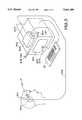
- FIG. 7is a simplified diagram of a head position sensing system implemented according to the present invention.
- FIG. 8is a block diagram of an envelope detection circuit.
- FIG. 1provides an illustration of the basic concept.
- a position sensoraccording to the present invention includes a transmitter 10 which is mounted on an object 11, the position of which is to be sensed.
- the transmitter 10generates a sequence of RF pulses 12 in response to a transmit timing signal supplied across a timing cable 13 from a control circuit 14.
- the receiver 15 coupled to the control circuit 14includes a sample circuit which samples the RF pulse with controlled timing in response to a receive timing signal.
- the sensor control circuit 14supplies the receive timing signal through a controlled delay circuit 16 to the receiver 15 so that the sequence of electromagnetic pulses are sampled with a time between transmitting of pulses from the transmitter 10 and sampling by the receiver 15 precisely controlled and swept over a range of delays.
- the receivergenerates a sample signal on line 17, which is supplied to the sensor control circuit 14 which detects a characteristic of the sample signal to indicate a time-of-flight of the RF pulses 12 from the transmitter 10 to the receiver 15.
- a first additional receiver 18 and a second additional receiver 19are included in the system.
- the receivers 18 and 19are connected to the control circuit 14 by timing cables 20 and 21, respectively, and also sample the RF pulses 12 with controlled timing.
- the time-of-flight detected in response to the receivers 15, 18 and 19can be processed to indicate the position of the object 11 with a number of degrees of freedom and with excellent resolution according to the present invention. Also the range indicated by bracket 22 between the transmitter 10 and the receivers 15, 18, 19 may be less than 10 feet.
- the operation of the sensor according to the present inventioncan be better understood with respect to the block diagram in FIG. 2.
- the systemis based on a pulse timing oscillator 50 which generates a clock at a pulse repetition rate of about two megahertz in the example to be illustrated with respect to FIG. 2.
- the pulse rate clock generated by the pulse timing oscillatoris supplied across a cable 51 to a pulse generator 52 in the transmitter.
- the pulse generatorgenerates an RF pulse, such as centered at nominally 2.0 gigaHertz, which is transmitted by the transmitter 53 through antenna 54 with the pulse repetition rate of about two megaHertz.
- the pulse timing oscillator 50is also coupled to a controlled delay circuit 55.
- the controlled delay circuit 55supplies a receive timing signal on line 56 to a receive strobe generator 57.
- the receive strobe generator 57strobes a sample gate in the receiver 58 at the pulse repetition rate, but at times which are delayed relative to the time that the transmitter emits the RF pulse.
- the controlled delay circuit 55is controlled by a start/stop circuit 59 which includes a sweep oscillator which oscillates at about 70 Hertz in the example described.
- the sweep oscillatoris designed to oscillate at less than 100 Hertz.
- An alternative systemmay be implemented which sweeps at about 16 kiloHertz to be compatible with NTSC video.
- This oscillatorsupplies a ramp signal on line 60 to the swept delay circuit 55 to control the timing of the strobes generated by the strobe generator 57.
- the start/stop circuit 59generates a start signal at the beginning of each sweep, and a stop signal in response to a pulse detect signal on line 61.
- the pulse detect signal on line 61is generated by the receiver 58 in response to the samples of the sequence of RF pulses.
- the pulse detect signal on line 61causes the start/stop circuit 59 to issue a stop signal.
- the start signalis used to initiate counter 62 and the stop signal is used to stop the counter 62.
- the counterbegins counting at a count rate of about 10 megaHertz in the example illustrated at the beginning of each sweep, and stops counting upon receiving the stop signal.
- the value in the counter 62 upon receiving the stop signalindicates the time-of-flight of an RF pulse from the transmitter to the receiver (the difference between the delay of a strobe pulse at the beginning of a sweep and the delay of a strobe pulse when the pulse detect signal is generated). This value is supplied to processor 63 which uses the information to determine the position of the transmitter 53.
- a ramp which lasts about 14 millisecondsis produced.
- the time between pulsesis about 500 nanoseconds.
- the delay between transmission by the transmitter and reception by the receiver for a 10-foot propagationwould be about 10 nanoseconds.
- the timing of the receive strobe generated by the receive strobe generatorcan be swept over a range of delays which begin at a time compensating for cable delay to the transmitter and varies by about 10 nanoseconds in order to precisely detect the position of the transmitter.
- the receiverwill sample about 28,600 pulses per sweep of the delay circuit 55.
- the RF pulses at the receivermay have an amplitude which varies as illustrated by trace 70.
- the 2.0 gigaHertz pulse generatorwill have a cycle time of about 500 picoseconds, with a rise time on the leading edge of less than 100 picoseconds.
- the leading edge of the pulsewill appear as a strong pulse as indicated at point 71.
- the strong pulsewill be followed by a noise region, generally 72, which is based on reflections and other effects of the transmitted pulse.
- the noisewill have died to a low level as indicated by the region 73 at the beginning of a real-time pulse cycle.
- This real-time pulsewill be sampled over a range of delay times, such that an equivalent time signal, as illustrated at trace 80, is produced.
- This tracewill assume the shape of the average pulse, however, with a repetition cycle of 70 Hertz for an equivalent time sample width of 14 milliseconds.
- the equivalent cycle time of the pulsewill be about 700 microseconds, for an equivalent time pulse frequency of about 1.4 kiloHertz.
- the receiverincludes an audio-frequency amplifier with automatic gain control, and a threshold detector. Upon detection of the threshold, such as indicated at point 81, the pulse detection signal is generated on line 61.
- the pulse timing oscillator 50can be connected to other transmitters, such as across cables 85 and other receivers, such as across cables 86 to produce a sophisticated position-detecting system.
- the pulse timing oscillator 50can be frequency modulated, or dithered, for the purpose of reducing interference from similar systems, or other RF devices.
- FIG. 3provides a more detailed schematic diagram of a time-of-flight sensor according to the present invention.
- the pulse repetition frequency of about 2.5 megaHertzis shown, which is generated by a 10 megaHertz clock 100 connected to a divide-by-four circuit 101.
- the output of the divide-by-four circuit 101provides a pulse rate clock on line 102.
- This signalis supplied to a driver 103 coupled to a timing cable 104.
- the timing cableis connected to the transmit unit, which includes a driver 105, a pulse-forming network 106 which is responsive to the driver 105, and a microwave oscillator 107 which generates, for example, a two gigaHertz, gated RF pulse on line 108.
- Line 108is coupled to a transmit antenna 109 which transmits the RF pulse 110 to a receive antenna 111.
- the pulse timing signal on line 102is supplied as a trigger signal to a voltage controlled delay circuit 112.
- the output of the voltage controlled delay circuit on line 113drives a pulse-forming network 114 which is used to strobe a sample-and-hold gate 115, which is connected to receive antenna 111 and supplies a sample of the transmitted pulse to a holding capacitance 116.
- the holding capacitancedrives an amplifier 117 to produce a sample signal on line 118.
- the sample signalis supplied to a comparator 119 which compares the sample signal against a threshold 120.
- the sample signal line 118drives a peak-detect circuit 139 which is based on a diode 120 and capacitor 121.
- the output of the peak-detect circuitis supplied to an amplifier 122 which provides automatic gain control to the amplifier 117.
- the automatic gain control ampincludes an input resistor 123 which is connected to the first input of a differential amplifier 124.
- the second input of differential amplifier 124is connected to a reference voltage 125.
- Capacitor 126is connected in feedback across the amp 124.
- the voltage controlled delay circuitis controlled in response to a ramp signal on line 127, which is supplied by ramp generator 128.
- the ramp signal on line 127causes the voltage controlled delay to sweep over a range of delays which corresponds to the delay of the timing cable 104 plus a range of expected time-of-flights from the transmit unit to the receiver.
- This ramp generator 128is driven by a ramp clock 130.
- the ramp clock in the example illustratedis generated by dividing the pulse repetition frequency on line 102 by 2 16 to produce a 40 Hertz signal on line 131.
- the 40-Hertz signalis coupled to a binary storage element 132. On the leading edge of the ramp clock, the output of the binary 132 is set high, enabling the AND gate 133 to supply the 10 megaHertz clock to a range counter 134.
- the range countercounts up at the 10 megaHertz rate until the comparator 119 detects that the sample signal on line 118 exceeds the threshold. At that point, the binary storage element 132 is reset, disabling the AND gate 133 and turning off the range counter 134. The data in the range counter can then be supplied out across bus 135 to the signal processor. Also, on the leading edge of each 40 Hertz ramp, a reset signal is supplied to control circuit 136 which resets the counter 134 for a subsequent sweep.
- a 2.5 megaHertz repetition frequencyis derived from the 10 megaHertz clock.
- the pulse repetition frequencydrives the transmit unit through the timing cable, which may be implemented with low-cost phonocables that carry DC power as well as the clock.
- the transmittercomprises a pulse forming network (PFN) that modulates a gated RF oscillator to generate one cycle of RF as shown at, for example, two gigaHertz center frequency.
- PPNpulse forming network
- the RF monocyclepropagates from the transmit antenna to the receive antenna.
- a sample hold circuit in the receive unitsamples the receive signal when driven with a gate pulse derived from the voltage controlled delay circuit and a pulse-forming network.
- the hold circuit outputis amplified by an automatic gain controlled amplifier and applied to a threshold comparator.
- the output of the amplifier 117is an equivalent time replica of the RF pulse that repeats at a 40 Hertz rate, the sweep rate of the ramp generator.
- a peak detectordetects the maximum pulse amplitude in the equivalent time sample signal and drives an automatic gain control amplifier to maintain the peak amplitude of the equivalent time pulse at a controlled level, typically -1 peak volts in this example.
- the comparatoris typically set to -0.5 volts to detect the equivalent time pulse at a precise, constant percentage with a maximum level regardless of fluctuation caused by time-of-flight range or antenna orientation.
- the equivalent time signalrepresents a range sweep from one to ten feet as defined by the ramp circuit and the voltage controlled delay circuit.
- a binaryis toggled to start the range counter by gating the 10 megaHertz clock into the range counter.
- the range counteris stopped, leaving the exact range count for readout. This cycle is repeated at a 25 millisecond rate.
- 10 megaHertz count rate250,000 counts represent full scale, or ten feet, so the digital resolution is in the neighborhood of 0.0006 inches.
- present systemsare analog-noise limited to about 0.01 inches at the 25 millisecond update rate. Digital averaging may be employed to decrease jitter.
- the voltage controlled delay circuit 112generates a linear-range sweep over time by employing a primitive exponential, high-speed voltage ramp with the time constant of about 10 nanoseconds. This ramp is combined with a primitive exponential ramp in the ramp circuit. Both the real-time ramp and the equivalent-time ramp operate over the same portions of their curves to jointly provide a linear sweep.
- FIGS. 4 through 6A representative electrical schematic diagram of another example of a receiver, transmitter and timing circuit are illustrated in FIGS. 4 through 6.
- FIG. 4illustrates the timing circuit for the system according to the present invention.
- the timing circuitincludes a 70 Hertz oscillator, which is formed using NAND gates 200 and 201 which have their inputs connected together to operate as inverters.
- the first NAND gate 200has its output connected to the input of the second NAND gate 201.
- the second NAND gate 201is connected through a capacitor 202 in feedback to the input of the first NAND gate 200.
- the output of NAND gate 200is connected through resistor 203 to its input.
- This 70 Hertz clockis connected to a flip-flop through the RC differentiator composed of capacitor 204 and resistor 205, which is connected to the positive five-volt supply.
- the flip-flopis based on NAND gate 206 and NAND gate 207.
- the output NAND gate 206is connected to one input of NAND gate 207.
- the output of NAND gate 207is connected to one input of NAND gate 206.
- the first input of NAND gate 206is the output of the RC circuit based on capacitor 204 and resistor 205.
- the second input to NAND gate 207is the output of a threshold detection circuit at node 208.
- the threshold detection circuit at node 208is composed of resistor 209, which is connected to receive the sample signal, RX, generated by the receiver described in FIG. 6, and resistor 210, which is connected to the positive five-volt supply.
- the output of the flip-flop composed of NAND gates 206 and 207is supplied through resistor 211 to connector 212.
- the connector 212drives the signal processor, which is composed of counter 213 and memory 214.
- a 10 megaHertz clock 215drives a NAND gate 216.
- the second input to the NAND gate 216is the signal from connector 212, which enables and disables the output of the NAND gate 216 to drive the counter 213.
- the signal from connector 212is used as a read strobe for the memory on line 215, and a reset signal on line 216 for resetting the counter by appropriate control circuitry.
- the counteris enabled at the beginning of each cycle of the oscillator composed of NAND gates 200 and 201, and turned off when the received sample signal RX falls below a negative threshold.
- the system in FIG. 4also shows the pulse clock composed of inverter 220 and inverter 221.
- the output of inverter 220is connected through resistor 222 to its input.
- the output of inverter 221is connected through capacitor 223 to the input of inverter 220.
- the output of inverter 221is a2 megaHertz clock on line 224.
- This signalis supplied through inverter 225 to node 226.
- Capacitor 227is connected between node 226 and ground.
- Capacitor 228is connected between node 226 and a transmit cable 229 such as an RCA phono plug coupled to a 12-foot coaxial audiocable.
- inductor 230is coupled from cable 229 to the positive five-volt supply in order to supply power to the transmitter across the cable 229 superimposed with the transmit clock.
- the pulse clock on line 224is also supplied to a delay circuit which is connected to line 224 through resistor 231.
- Resistor 231is connected to the input of inverter 232 and through variable capacitor 233 to ground.
- the variable capacitor 233provides a coarse delay for the pulse clock.
- the output of inverter 232is supplied through resistor 234 to the input of inverter 235.
- the input of inverter 235is also driven by the ramp generator, generally 246.
- the output of inverter 235is supplied through inverter 236 to the receive strobe generator through capacitor 237.
- Capacitor 237is connected between the output of inverter 236 and node 238.
- Diode 239has its anode connected to node 238 and its cathode connected to ground.
- Resistor 240is connected between node 238 and the five-volt supply. Node 238 is also connected to the emitter of high-speed transistor 241. The base of transistor 241 is coupled to ground. The collector of transistor 241 supplies the strobe signal STB on line 242. Also, the collector of transistor 241 is connected through resistor 243 to the positive five-volt supply.
- the ramp generator 246is basically an analog exponential ramp generator. This ramp generator may be replaced by a digital-to-analog converter which digitally supplies a sequence of analog values to the input of inverter 235 to control the delay using synchronous oscillators.
- the 70 Hertz clock at the output of the NAND gate 200is supplied on line 250 through resistor 251 and the capacitor 252 to the base of transistor 253.
- resistor 254is connected from the base of transistor 253 to ground.
- Emitter of transistor 253is coupled to ground.
- the collector of transistor 253is connected through resistor 255 to the positive five-volt supply. Also the collector is coupled through capacitor 256 to ground.
- Resistor 257is connected from the positive five-volt supply to the input of inverter 235.
- Resistor 258is connected from the collector of transistor 253 to the input of inverter 235. Also, controllable capacitor 259 is connected from the input of inverter 235 to ground. This circuit serves to bias the input of inverter 235 to a region in which it has an exponential transfer function.
- the ramp generator 246generates a complimentary exponential transfer function to provide overall a linear ramp in delay at the output of inverter 235. Fine control over the span of the range of delays produced is provided by the adjustable capacitor 259.
- the power supplyincludes a battery 270.
- the batteryis connected to a switch 271 which drives level translators 272 and 273 to provide isolated five-volt supplies for the circuit.
- transmit timing signal and the receive timing signalare produced using a single clock in the embodiment described, alternative systems may employ timing circuits which have separate synchronized clocks located at the receiver and transmitter, respectively, without a cable tether.
- FIG. 5illustrates the implementation of a transmitter according to the present invention.
- This transmitterincludes a connector 300 which can be connected to the cable 229 illustrated in FIG. 4. This cable supplies DC power and the transmit clock to a pulse-forming network in the transmitter.
- connector 300is coupled through inductor 301 to line 302.
- the connector 300is connected through capacitor 303 to node 304.
- Resistor 305is connected from node 304 to line 302.
- Diode 306has its cathode coupled to node 304 and its anode coupled to ground.
- Diode 307has its anode coupled to node 304 and its cathode coupled to line 302.
- Line 302is coupled through capacitor 308 to ground.
- Node 304is coupled through inverters 309 and 310 in series which shape the incoming signal.
- the output of inverter 310is supplied through capacitor 311 to node 312.
- the anode of diode 313is coupled to node 312.
- the cathode of diode 313is coupled to ground.
- Node 312is connected through resistor 314 to line 302.
- node 312is connected through resistor 315 to the emitter of a high-speed transistor 316.
- the base of high-speed transistor 316is connected through inductor 317 to ground.
- Collector of transistor 316is connected to the transmit antenna. 318. Also, the collector is coupled through inductor 319 to node 320.
- Node 320is coupled through resistor 321 to line 302 and across capacitor 322 to ground.
- the transmit antenna 318is connected through resistor 323 and capacitor 324 to ground.
- the transmittergenerates a short burst of radio frequency energy at the transmit antenna 318.
- the antennamay be a vertically polarized antenna, a circularly polarized antenna, antennae based on cross-dipoles or other implementations known in the arts. Also, the antenna may be dithered or otherwise maneuvered to improve sensitivity of the receiver.
- the use of the pulsed RF systemhas a very low average power, complying with FCC Part 15 regulations.
- FIG. 6illustrates a receiver for use with the system of the present invention.
- the receiverincludes a receive antenna 350 and a single diode sample gate based on diode 351.
- the cathode of diode 351is connected to the receive antenna 350.
- the strobe signal from line 242 of FIG. 4is supplied through capacitor 352 to the cathode 353 diode 351.
- Resistor 353is coupled from the cathode of diode 351 to ground.
- the anode of diode 351is coupled to node 354.
- Capacitor 355holds the sampled voltage between node 354 and ground.
- a resistor 356is coupled from node 354 to the positive five-volt supply.
- Node 354is connected through capacitor 397 to the base of transistor 357.
- the emitter of transistor 357is connected to ground.
- a resistor 358is connected in feedback from the collector of transistor 357 to its base.
- the collector of transistor 357is connected through capacitor 398 to a sequence of audio amplifiers beginning with inverter 359, having resistor 360 in feedback.
- the output of inverter 359is connected through capacitor 361 and resistor 362 to the input of inverter 363.
- Inverter 363has resistor 364 and capacitor 365 connected in parallel in feedback from the output to the input.
- the output of inverter 363is connected through capacitor 366 and resistor 367 of the input of inverter 368.
- Inverter 368has resistor 369 and capacitor 370 connected in feedback in parallel.
- the output of inverter 368is an equivalent time sample signal on line 371.
- This signalis supplied across resistor 372 to the input of inverter 373.
- the output of inverter 373is supplied to the anode of diode 374.
- the cathode of diode 374is connected to node 375, which is connected across capacitor 376 to ground.
- a resistor 377is connected from node 375 to the input of inverter 373.
- Node 375is connected through resistor 378 to the input of inverter 379.
- Inverter 379has capacitor 380 in feedback and its input is connected across resistor 381 to ground.
- the output of inverter 379is connected through resistor 382 to the collector of transistor 357 and provides automatic gain control for the amplifier sequence in response to the voltage generated on capacitor 376.
- the equivalent time signal on line 371is also connected through capacitor 383 and resistor 384 to node 385.
- Node 385is connected across capacitor 386 to ground and resistor 387 to ground. It is also connected to a video output connector 388 for connection to an analyzing circuit.
- the signal on line 371is supplied as the equivalent time signal RX to the threshold detector shown in FIG. 4.
- the values of the resistors and capacitorsare illustrated in FIGS. 4 through 6 for the example circuit shown.
- the NAND gatesare 74HC00 and the inverters are 74AC04, except in the receiver in which the inverters are implemented using MC14069UB inverters.
- the sample circuituses a single-ended, single diode sample gate, which operates with low power and high efficiency for sampling the small signals at the fast rate required by the present invention.
- Other receiver topologiesmight be used, such as those described in my co-pending U.S. patent application entitled Ultra-Wide Band Receiver, application Ser. No. 08/044,745, filed Apr. 12, 1993, now U.S. Pat. No. 5,345.471, issued Sep. 6, 1994, owned at the time of invention and currently by the same assignee as the present invention. Such application is incorporated by reference in order to teach alternative receiver topologies.
- FIG. 7illustrates a simple head position sensing system implemented according to the present invention.
- a transmitter 500is mounted on a user's headset 501, worn by a user of a computer system 502.
- the receiver box 503is mounted on the computer system 502 and connected across cable 504 to a standard mouse interface.
- the receiver box 503includes a first receiver 505, a second receiver 506 and a third receiver 507 each generating a time-of-flight measurement for pulses generated by the transmitter 501.
- the receiver box 503produces data indicating the time-of-flight from the transmitter 500 to each of the three receivers 505, 506, 507 can be used for precise position detection of the transmitter 500 mounted on the headset 501.
- Computer system 502includes the standard monitor 510 and keyboard 511 and may be used for executing interactive computer programming based on the position data produced according to the present invention.
- Various arrangements of the transmitters and receiversmay be used to triangulate, providing six axis information: x, y, z in translation and 3 axes of rotation for the transmitter 500.
- a very high resolution position sensing systemhas been provided based on direct time-of-flight measurement of radio frequency pulses.
- the systemis simple and highly accurate, greatly improving over prior systems for providing this type of information.
- the systemis capable of providing submillimeter resolution made with components costing less than about $10.00.
- the inventioncan be applied to interactive media systems, robotics, automotive occupant position sensing, digital surgery, and a wide variety of other applications where high resolution position sensing is desired.
- an envelope detector 140can be added to the baseband analog output appearing on line 118 between amplifier 117 and comparator 119 to eliminate a problem that occurs when the orientation of the receive and transmit antennas 111, 109 are not matched, e.g., one is upright and one is inverted. Without the envelope detector 140, the waveform appearing on line 118 becomes inverted when either the transmitter or the receiver antenna becomes inverted relative to the other. This can happen during routine installation or during activities related to position sensing using the device, such as robotics control. When the waveform is inverted, leading edge triggering of comparator 119 occurs on the second receive lobe 142 appearing on line 118 instead of the first receive lobe 141, as shown in FIG. 8, resulting in an error in position determination amounting to 1/2 an RF cycle, typically about 3 inches.
- the envelope detector 140 added between amplifier 117 and comparator 119 on line 118comprises an absolute value circuit 143 followed by a low pass filter 144, as shown in FIG. 8.
- Envelope detector 140resolves this problem by taking the absolute value of the equivalent time signal to make it polarity insensitive. Thus the leading lobe 145 of the absolute value signal is always of the correct polarity.
- a low pass filter 144is added to smooth the absolute-value/rectified signal into a clean pulse 146 prior to threshold detection by comparator 119. This process allows for smooth degradation in accuracy should the leading lobe in the received pulse become degraded due to multipath RF propagation or antenna sidelobe nulls.
- low pass filter 144has a linear phase characteristic in its passband, such as a Bessel characteristic, and a stop band null located at the periodicity of the input signal, such as a Chebychev stop band characteristic.
- Antennas (T) 109 and (R) 111are generally linearly polarized monopoles, dipoles, or horns. However rotational independence can be achieved with circularly polarized antennas, such as cavity-backed spirals or turnstile antennas. Even with these antennas, nulls in the leading edge can occur due to multipath or antenna sidelobe nulls, so the envelope detector 140 can be used for increased positional accuracy.
Landscapes
- Engineering & Computer Science (AREA)
- Remote Sensing (AREA)
- Radar, Positioning & Navigation (AREA)
- Physics & Mathematics (AREA)
- General Physics & Mathematics (AREA)
- Computer Networks & Wireless Communication (AREA)
- Electromagnetism (AREA)
- Life Sciences & Earth Sciences (AREA)
- Environmental & Geological Engineering (AREA)
- Geology (AREA)
- General Life Sciences & Earth Sciences (AREA)
- Geophysics (AREA)
- Thermal Sciences (AREA)
- Fluid Mechanics (AREA)
- Radar Systems Or Details Thereof (AREA)
Abstract
Description
Claims (12)
Priority Applications (1)
| Application Number | Priority Date | Filing Date | Title |
|---|---|---|---|
| US08/636,370US5661490A (en) | 1993-04-12 | 1996-04-23 | Time-of-flight radio location system |
Applications Claiming Priority (4)
| Application Number | Priority Date | Filing Date | Title |
|---|---|---|---|
| US08/044,745US5345471A (en) | 1993-04-12 | 1993-04-12 | Ultra-wideband receiver |
| US08/058,398US5457394A (en) | 1993-04-12 | 1993-05-07 | Impulse radar studfinder |
| US08/300,909US5510800A (en) | 1993-04-12 | 1994-09-06 | Time-of-flight radio location system |
| US08/636,370US5661490A (en) | 1993-04-12 | 1996-04-23 | Time-of-flight radio location system |
Related Parent Applications (1)
| Application Number | Title | Priority Date | Filing Date |
|---|---|---|---|
| US08/300,909Continuation-In-PartUS5510800A (en) | 1993-04-12 | 1994-09-06 | Time-of-flight radio location system |
Publications (1)
| Publication Number | Publication Date |
|---|---|
| US5661490Atrue US5661490A (en) | 1997-08-26 |
Family
ID=27366544
Family Applications (1)
| Application Number | Title | Priority Date | Filing Date |
|---|---|---|---|
| US08/636,370Expired - LifetimeUS5661490A (en) | 1993-04-12 | 1996-04-23 | Time-of-flight radio location system |
Country Status (1)
| Country | Link |
|---|---|
| US (1) | US5661490A (en) |
Cited By (89)
| Publication number | Priority date | Publication date | Assignee | Title |
|---|---|---|---|---|
| WO1999054173A1 (en)* | 1998-04-20 | 1999-10-28 | Automotive Systems Laboratory, Inc. | Occupant detection system |
| US5986602A (en)* | 1998-03-02 | 1999-11-16 | Remote Data Systems, Inc. | Pulse radar device and method |
| US6023638A (en)* | 1995-07-28 | 2000-02-08 | Scimed Life Systems, Inc. | System and method for conducting electrophysiological testing using high-voltage energy pulses to stun tissue |
| US6054950A (en)* | 1998-01-26 | 2000-04-25 | Multispectral Solutions, Inc. | Ultra wideband precision geolocation system |
| US6067673A (en)* | 1997-07-18 | 2000-05-30 | Kohler Company | Bathroom fixture using radar detector having leaky transmission line to control fluid flow |
| US6100877A (en)* | 1998-05-14 | 2000-08-08 | Virtual Ink, Corp. | Method for calibrating a transcription system |
| US6107699A (en)* | 1998-05-22 | 2000-08-22 | Scimed Life Systems, Inc. | Power supply for use in electrophysiological apparatus employing high-voltage pulses to render tissue temporarily unresponsive |
| US6111565A (en)* | 1998-05-14 | 2000-08-29 | Virtual Ink Corp. | Stylus for use with transcription system |
| US6124847A (en)* | 1998-05-14 | 2000-09-26 | Virtual Ink, Corp. | Collapsible detector assembly |
| US6133876A (en)* | 1998-03-23 | 2000-10-17 | Time Domain Corporation | System and method for position determination by impulse radio |
| US6142059A (en)* | 1996-11-27 | 2000-11-07 | Case Corporation | Method and apparatus for sensing the orientation of a mechanical actuator |
| US6147681A (en)* | 1998-05-14 | 2000-11-14 | Virtual Ink, Corp. | Detector for use in a transcription system |
| US6177903B1 (en) | 1999-06-14 | 2001-01-23 | Time Domain Corporation | System and method for intrusion detection using a time domain radar array |
| US6177927B1 (en) | 1998-05-14 | 2001-01-23 | Virtual Ink Corp. | Transcription system kit |
| US6191778B1 (en) | 1998-05-14 | 2001-02-20 | Virtual Ink Corp. | Transcription system kit for forming composite images |
| US6199902B1 (en) | 1999-02-12 | 2001-03-13 | Trw Inc. | Apparatus and method for discerning at least one occupant characteristic via absorption of an energy signal |
| US6206340B1 (en) | 1997-07-18 | 2001-03-27 | Kohler Company | Radar devices for low power applications and bathroom fixtures |
| US6211863B1 (en) | 1998-05-14 | 2001-04-03 | Virtual Ink. Corp. | Method and software for enabling use of transcription system as a mouse |
| US6218979B1 (en) | 1999-06-14 | 2001-04-17 | Time Domain Corporation | Wide area time domain radar array |
| US6236035B1 (en) | 1998-11-25 | 2001-05-22 | Trw Inc. | Apparatus and method for sensing with triangulation and time-of-flight for use in an actuatable occupant restraint system |
| US6239736B1 (en) | 1999-04-21 | 2001-05-29 | Interlogix, Inc. | Range-gated radar motion detector |
| US6250601B1 (en) | 1997-07-18 | 2001-06-26 | Kohler Company | Advanced touchless plumbing systems |
| US6290255B1 (en) | 1997-03-07 | 2001-09-18 | Automotive Systems Laboratory, Inc. | Occupant detection system |
| US6295019B1 (en) | 1998-05-26 | 2001-09-25 | Time Domain Corporation | System and method for distance measurement by inphase and quadrature signals in a radio system |
| US6302438B1 (en) | 1998-04-21 | 2001-10-16 | Automotive Systems Laboratory, Inc. | Occupant detection system |
| US6310615B1 (en) | 1998-05-14 | 2001-10-30 | Virtual Ink Corporation | Dual mode eraser |
| US6351246B1 (en) | 1999-05-03 | 2002-02-26 | Xtremespectrum, Inc. | Planar ultra wide band antenna with integrated electronics |
| US6396454B1 (en)* | 2000-06-23 | 2002-05-28 | Cue Corporation | Radio unit for computer systems |
| US6428537B1 (en) | 1998-05-22 | 2002-08-06 | Scimed Life Systems, Inc. | Electrophysiological treatment methods and apparatus employing high voltage pulse to render tissue temporarily unresponsive |
| US6462662B1 (en) | 1998-04-13 | 2002-10-08 | Prompt Technologies Inc. | Method and apparatus for remote cueing in the performing arts |
| US6483461B1 (en) | 2000-08-24 | 2002-11-19 | Time Domain Corporation | Apparatus and method for locating objects in a three-dimensional space |
| US20030053554A1 (en)* | 1997-12-12 | 2003-03-20 | Xtreme Spectrum, Inc. | Ultra wide bandwidth spread-spectrum communications system |
| US20030058971A1 (en)* | 2001-09-21 | 2003-03-27 | Langford David W. | Impulse radio receiver and method for finding angular offset of an impulse radio transmitter |
| US6590545B2 (en) | 2000-08-07 | 2003-07-08 | Xtreme Spectrum, Inc. | Electrically small planar UWB antenna apparatus and related system |
| US6603818B1 (en) | 1999-09-23 | 2003-08-05 | Lockheed Martin Energy Research Corporation | Pulse transmission transceiver architecture for low power communications |
| US6700538B1 (en) | 2000-03-29 | 2004-03-02 | Time Domain Corporation | System and method for estimating separation distance between impulse radios using impulse signal amplitude |
| US6722260B1 (en) | 2002-12-11 | 2004-04-20 | Rosemount Inc. | Hydraulic piston position sensor |
| US6725027B1 (en)* | 1999-07-22 | 2004-04-20 | Mitsubishi Denki Kabushiki Kaisha | Multipath noise reducer, audio output circuit, and FM receiver |
| US6722261B1 (en) | 2002-12-11 | 2004-04-20 | Rosemount Inc. | Hydraulic piston position sensor signal processing |
| US6738044B2 (en) | 2000-08-07 | 2004-05-18 | The Regents Of The University Of California | Wireless, relative-motion computer input device |
| WO2004046749A3 (en)* | 2002-11-19 | 2004-07-08 | Radatec Inc | Method and system for calibration of a phase-based sensing system |
| US20040152988A1 (en)* | 2003-01-31 | 2004-08-05 | Weirich John Paul | Capsule imaging system |
| US6906625B1 (en) | 2000-02-24 | 2005-06-14 | Time Domain Corporation | System and method for information assimilation and functionality control based on positioning information obtained by impulse radio techniques |
| US20050165576A1 (en)* | 2004-01-26 | 2005-07-28 | Jesmonth Richard E. | System and method for generating three-dimensional density-based defect map |
| US20050170778A1 (en)* | 2003-10-17 | 2005-08-04 | Fujitsu Component Limited | Pointing device and receiving unit with UWB signal |
| US20060033662A1 (en)* | 2004-07-27 | 2006-02-16 | Ubisense Limited | Location system |
| US20060066095A1 (en)* | 2004-09-27 | 2006-03-30 | Haack Douglas F | V-fold information presentation device |
| US20060152404A1 (en)* | 2005-01-07 | 2006-07-13 | Time Domain Corporation | System and method for radiating RF waveforms using discontinues associated with a utility transmission line |
| EP1707980A1 (en)* | 2005-03-31 | 2006-10-04 | Deere & Company | Method for configuring a local positioning system |
| US20070018792A1 (en)* | 2004-03-17 | 2007-01-25 | Brother Kogyo Kabushiki Kaisha | Position detecting system, responder and interrogator, wireless communication system, position detecting method, position detecting program, and information recording medium |
| US20070176826A1 (en)* | 2004-06-07 | 2007-08-02 | Commissariat A L'energie Atomique | Ulb location system for rescuing avalanche victims |
| US20070196621A1 (en)* | 2006-02-02 | 2007-08-23 | Arnold Frances | Sprayable micropulp composition |
| US20070242735A1 (en)* | 2006-01-31 | 2007-10-18 | Regents Of The University Of Minnesota | Ultra wideband receiver |
| US20080024355A1 (en)* | 2006-06-06 | 2008-01-31 | Sony Corporation | Method and apparatus for measuring distance between a target and a receiver in a ranging system |
| US20080125054A1 (en)* | 2006-11-27 | 2008-05-29 | Jean-Louis Laroche | Method and system for determining a time delay between transmission and reception of an rf signal in a noisy rf environment using phase detection |
| US20080151967A1 (en)* | 1999-06-14 | 2008-06-26 | Time Domain Corporation | Time transfer using ultra wideband signals |
| US20080165046A1 (en)* | 1999-06-14 | 2008-07-10 | Time Domain Corporation | System and method for intrusion detection using a time domain radar array |
| US20080231498A1 (en)* | 2004-11-15 | 2008-09-25 | Lars Menzer | Symmetrical Multi-Path Method For Determining the Distance Between Two Transmitter-Receivers |
| US20080252293A1 (en)* | 2006-05-22 | 2008-10-16 | Interuniversitair Microelektronica Centrum Vzw (Imec) | Detection of resonant tags by ultra-wideband (uwb) radar |
| US20080290923A1 (en)* | 2007-05-25 | 2008-11-27 | Niitek, Inc | Systems and methods for providing delayed signals |
| US20080291080A1 (en)* | 2007-05-25 | 2008-11-27 | Niitek, Inc | Systems and methods for providing trigger timing |
| WO2009042095A2 (en) | 2007-09-26 | 2009-04-02 | Stryker Corporation | System for preventing unintended activation of a medical device by a portable remote control console |
| US20090198467A1 (en)* | 2004-06-04 | 2009-08-06 | Koninklijke Philips Electronics, N.V. | Measuring Clock Jitter |
| US7616676B2 (en) | 1998-12-11 | 2009-11-10 | Freescale Semiconductor, Inc. | Method and system for performing distance measuring and direction finding using ultrawide bandwidth transmissions |
| US20090295617A1 (en)* | 2007-09-07 | 2009-12-03 | Steven Lavedas | System, Method, and Computer Program Product Providing Three-Dimensional Visualization of Ground Penetrating Radar Data |
| US7652619B1 (en)* | 2007-05-25 | 2010-01-26 | Niitek, Inc. | Systems and methods using multiple down-conversion ratios in acquisition windows |
| EP2159605A1 (en) | 2008-09-02 | 2010-03-03 | Leica Geosystems AG | Radar measuring method for locating a concealed object embedded in a medium |
| US7692598B1 (en) | 2005-10-26 | 2010-04-06 | Niitek, Inc. | Method and apparatus for transmitting and receiving time-domain radar signals |
| US20100277283A1 (en)* | 2009-05-01 | 2010-11-04 | Burkart Scott M | Systems and methods for RFID tag operation |
| US20100277280A1 (en)* | 2009-05-01 | 2010-11-04 | Burkart Scott M | Systems and methods for relaying information with RFID tags |
| CN102047256A (en)* | 2008-05-27 | 2011-05-04 | 斯特赖克公司 | Wireless medical room control unit for controlling multiple medical devices |
| US20110133990A1 (en)* | 2009-12-09 | 2011-06-09 | Kent Kahle | System for determining position in a work space |
| US20110187537A1 (en)* | 2010-02-01 | 2011-08-04 | Touchton Scott F | Time of Flight Animal Monitoring |
| US8264401B1 (en) | 2011-12-29 | 2012-09-11 | Sensys Networks, Inc. | Micro-radar, micro-radar sensor nodes, networks and systems |
| US8368513B2 (en) | 2009-05-01 | 2013-02-05 | L-3 Communications Integrated Systems L.P. | Data separation in high density environments |
| US8456282B2 (en) | 2009-05-01 | 2013-06-04 | L-3 Communications Integrated Systems L.P. | Synchronization of devices in a RFID communications environment |
| US8700202B2 (en) | 2010-11-30 | 2014-04-15 | Trimble Navigation Limited | System for positioning a tool in a work space |
| US8847808B1 (en)* | 2013-05-08 | 2014-09-30 | Broadcom Corporation | Process, voltage, and temperature insensitive biasing |
| US8872674B1 (en) | 2011-10-19 | 2014-10-28 | Balu Subramanya | Directional speed and distance sensor |
| US9019150B2 (en) | 2011-02-21 | 2015-04-28 | TransRobotics, Inc. | System and method for sensing distance and/or movement |
| US9383436B2 (en) | 2012-01-18 | 2016-07-05 | Tdc Acquisition Holdings, Inc. | One way time of flight distance measurement |
| US9761049B2 (en) | 2014-03-28 | 2017-09-12 | Intel Corporation | Determination of mobile display position and orientation using micropower impulse radar |
| CN109983360A (en)* | 2016-08-18 | 2019-07-05 | 罗伯特·博世有限公司 | High safety motion sensor |
| US11004337B2 (en) | 2012-12-28 | 2021-05-11 | Balu Subramanya | Advanced parking management system |
| US11703593B2 (en) | 2019-04-04 | 2023-07-18 | TransRobotics, Inc. | Technologies for acting based on object tracking |
| US11717189B2 (en) | 2012-10-05 | 2023-08-08 | TransRobotics, Inc. | Systems and methods for high resolution distance sensing and applications |
| US11859375B2 (en) | 2009-12-16 | 2024-01-02 | Kohler Co. | Touchless faucet assembly and method of operation |
| CN118731909A (en)* | 2024-09-02 | 2024-10-01 | 成都量芯集成科技有限公司 | A pulse laser radar device based on FPGA |
| US12375924B2 (en) | 2019-01-28 | 2025-07-29 | Lambda:4 Entwicklungen Gmbh | Method for detecting the time of the earliest reception of a signal change, in particular for measuring delay time or for defense against relay attacks |
Citations (7)
| Publication number | Priority date | Publication date | Assignee | Title |
|---|---|---|---|---|
| US3687556A (en)* | 1970-09-18 | 1972-08-29 | Oceanography Dev Corp | Navigation system |
| US4161730A (en)* | 1977-10-17 | 1979-07-17 | General Electric Company | Radio determination using satellites transmitting timing signals with correction by active range measurement |
| US4543580A (en)* | 1982-01-15 | 1985-09-24 | Atlantic Scientific Corporation | System for lightning ground stroke position by time of arrival discrimination |
| US5216429A (en)* | 1991-04-17 | 1993-06-01 | Ricoh Company, Ltd. | Position measuring system using pseudo-noise signal transmission and reception |
| US5497160A (en)* | 1993-09-17 | 1996-03-05 | Motorola, Inc. | Method and apparatus for improved auto-correlation and range correlation in pseudo-random noise coded systems |
| US5499029A (en)* | 1992-07-14 | 1996-03-12 | Eg&G Energy Measurements, Inc. | Wide band stepped frequency ground penetrating radar |
| US5510800A (en)* | 1993-04-12 | 1996-04-23 | The Regents Of The University Of California | Time-of-flight radio location system |
- 1996
- 1996-04-23USUS08/636,370patent/US5661490A/ennot_activeExpired - Lifetime
Patent Citations (8)
| Publication number | Priority date | Publication date | Assignee | Title |
|---|---|---|---|---|
| US3687556A (en)* | 1970-09-18 | 1972-08-29 | Oceanography Dev Corp | Navigation system |
| US4161730A (en)* | 1977-10-17 | 1979-07-17 | General Electric Company | Radio determination using satellites transmitting timing signals with correction by active range measurement |
| US4543580A (en)* | 1982-01-15 | 1985-09-24 | Atlantic Scientific Corporation | System for lightning ground stroke position by time of arrival discrimination |
| US4543580B1 (en)* | 1982-01-15 | 1993-01-26 | Atlantic Scient Corp | |
| US5216429A (en)* | 1991-04-17 | 1993-06-01 | Ricoh Company, Ltd. | Position measuring system using pseudo-noise signal transmission and reception |
| US5499029A (en)* | 1992-07-14 | 1996-03-12 | Eg&G Energy Measurements, Inc. | Wide band stepped frequency ground penetrating radar |
| US5510800A (en)* | 1993-04-12 | 1996-04-23 | The Regents Of The University Of California | Time-of-flight radio location system |
| US5497160A (en)* | 1993-09-17 | 1996-03-05 | Motorola, Inc. | Method and apparatus for improved auto-correlation and range correlation in pseudo-random noise coded systems |
Cited By (163)
| Publication number | Priority date | Publication date | Assignee | Title |
|---|---|---|---|---|
| US6679269B2 (en) | 1995-07-28 | 2004-01-20 | Scimed Life Systems, Inc. | Systems and methods for conducting electrophysiological testing using high-voltage energy pulses to stun tissue |
| US6212426B1 (en) | 1995-07-28 | 2001-04-03 | Scimed Life Systems, Inc. | Systems and methods for conducting electrophysiological testing using high-voltage energy pulses to stun tissue |
| US6023638A (en)* | 1995-07-28 | 2000-02-08 | Scimed Life Systems, Inc. | System and method for conducting electrophysiological testing using high-voltage energy pulses to stun tissue |
| US6421556B2 (en) | 1995-07-28 | 2002-07-16 | Scimed Life Systems, Inc. | Systems and methods for conducting electrophysiological testing using high-voltage energy pulses to stun tissue |
| US6142059A (en)* | 1996-11-27 | 2000-11-07 | Case Corporation | Method and apparatus for sensing the orientation of a mechanical actuator |
| US6290255B1 (en) | 1997-03-07 | 2001-09-18 | Automotive Systems Laboratory, Inc. | Occupant detection system |
| US6067673A (en)* | 1997-07-18 | 2000-05-30 | Kohler Company | Bathroom fixture using radar detector having leaky transmission line to control fluid flow |
| US6388609B2 (en) | 1997-07-18 | 2002-05-14 | Kohler Company | Radar devices for low power applications and bathroom fixtures |
| US6206340B1 (en) | 1997-07-18 | 2001-03-27 | Kohler Company | Radar devices for low power applications and bathroom fixtures |
| US6568655B2 (en) | 1997-07-18 | 2003-05-27 | Kohler Company | Radar devices for low power applications and bathroom fixtures |
| US6250601B1 (en) | 1997-07-18 | 2001-06-26 | Kohler Company | Advanced touchless plumbing systems |
| US6901112B2 (en) | 1997-12-12 | 2005-05-31 | Freescale Semiconductor, Inc. | Ultra wide bandwidth spread-spectrum communications system |
| US6700939B1 (en) | 1997-12-12 | 2004-03-02 | Xtremespectrum, Inc. | Ultra wide bandwidth spread-spectrum communications system |
| US20030053555A1 (en)* | 1997-12-12 | 2003-03-20 | Xtreme Spectrum, Inc. | Ultra wide bandwidth spread-spectrum communications system |
| US20030053554A1 (en)* | 1997-12-12 | 2003-03-20 | Xtreme Spectrum, Inc. | Ultra wide bandwidth spread-spectrum communications system |
| US7408973B2 (en) | 1997-12-12 | 2008-08-05 | Freescale Semiconductor, Inc. | Ultra wide bandwidth spread-spectrum communications system |
| US6931078B2 (en) | 1997-12-12 | 2005-08-16 | Freescale Semiconductor, Inc. | Ultra wide bandwidth spread-spectrum communications systems |
| US20050259720A1 (en)* | 1997-12-12 | 2005-11-24 | Freescale Semiconductor, Inc. | Ultra wide bandwidth spread-spectrum communications system |
| US6054950A (en)* | 1998-01-26 | 2000-04-25 | Multispectral Solutions, Inc. | Ultra wideband precision geolocation system |
| US5986602A (en)* | 1998-03-02 | 1999-11-16 | Remote Data Systems, Inc. | Pulse radar device and method |
| US6297773B1 (en) | 1998-03-23 | 2001-10-02 | Time Domain Corporation | System and method for position determination by impulse radio |
| US6300903B1 (en) | 1998-03-23 | 2001-10-09 | Time Domain Corporation | System and method for person or object position location utilizing impulse radio |
| US6133876A (en)* | 1998-03-23 | 2000-10-17 | Time Domain Corporation | System and method for position determination by impulse radio |
| US6611234B2 (en) | 1998-03-23 | 2003-08-26 | Time Domain Corporation | System and method for position determination by impulse radio using round trip time-of-flight |
| US6462662B1 (en) | 1998-04-13 | 2002-10-08 | Prompt Technologies Inc. | Method and apparatus for remote cueing in the performing arts |
| WO1999054173A1 (en)* | 1998-04-20 | 1999-10-28 | Automotive Systems Laboratory, Inc. | Occupant detection system |
| US6220627B1 (en) | 1998-04-20 | 2001-04-24 | Automotive Systems Lab | Occupant detection system |
| US6302438B1 (en) | 1998-04-21 | 2001-10-16 | Automotive Systems Laboratory, Inc. | Occupant detection system |
| US6111565A (en)* | 1998-05-14 | 2000-08-29 | Virtual Ink Corp. | Stylus for use with transcription system |
| US6310615B1 (en) | 1998-05-14 | 2001-10-30 | Virtual Ink Corporation | Dual mode eraser |
| US6147681A (en)* | 1998-05-14 | 2000-11-14 | Virtual Ink, Corp. | Detector for use in a transcription system |
| US6211863B1 (en) | 1998-05-14 | 2001-04-03 | Virtual Ink. Corp. | Method and software for enabling use of transcription system as a mouse |
| US6124847A (en)* | 1998-05-14 | 2000-09-26 | Virtual Ink, Corp. | Collapsible detector assembly |
| US6100877A (en)* | 1998-05-14 | 2000-08-08 | Virtual Ink, Corp. | Method for calibrating a transcription system |
| US6177927B1 (en) | 1998-05-14 | 2001-01-23 | Virtual Ink Corp. | Transcription system kit |
| US6191778B1 (en) | 1998-05-14 | 2001-02-20 | Virtual Ink Corp. | Transcription system kit for forming composite images |
| US6428537B1 (en) | 1998-05-22 | 2002-08-06 | Scimed Life Systems, Inc. | Electrophysiological treatment methods and apparatus employing high voltage pulse to render tissue temporarily unresponsive |
| US6107699A (en)* | 1998-05-22 | 2000-08-22 | Scimed Life Systems, Inc. | Power supply for use in electrophysiological apparatus employing high-voltage pulses to render tissue temporarily unresponsive |
| US6295019B1 (en) | 1998-05-26 | 2001-09-25 | Time Domain Corporation | System and method for distance measurement by inphase and quadrature signals in a radio system |
| US6236035B1 (en) | 1998-11-25 | 2001-05-22 | Trw Inc. | Apparatus and method for sensing with triangulation and time-of-flight for use in an actuatable occupant restraint system |
| US8451936B2 (en) | 1998-12-11 | 2013-05-28 | Freescale Semiconductor, Inc. | Method and system for performing distance measuring and direction finding using ultrawide bandwidth transmissions |
| US7616676B2 (en) | 1998-12-11 | 2009-11-10 | Freescale Semiconductor, Inc. | Method and system for performing distance measuring and direction finding using ultrawide bandwidth transmissions |
| US6199902B1 (en) | 1999-02-12 | 2001-03-13 | Trw Inc. | Apparatus and method for discerning at least one occupant characteristic via absorption of an energy signal |
| US6239736B1 (en) | 1999-04-21 | 2001-05-29 | Interlogix, Inc. | Range-gated radar motion detector |
| US6351246B1 (en) | 1999-05-03 | 2002-02-26 | Xtremespectrum, Inc. | Planar ultra wide band antenna with integrated electronics |
| US20080100498A1 (en)* | 1999-06-14 | 2008-05-01 | Time Domain Corporation | System and method for intrusion detection using a time domain radar array |
| US7417581B2 (en) | 1999-06-14 | 2008-08-26 | Time Domain Corporation | System and method for intrusion detection using a time domain radar array |
| US6400307B2 (en) | 1999-06-14 | 2002-06-04 | Time Domain Corporation | System and method for intrusion detection using a time domain radar array |
| US7358888B2 (en) | 1999-06-14 | 2008-04-15 | Time Domain | System and method for intrusion detection using a time domain radar array |
| US20080151967A1 (en)* | 1999-06-14 | 2008-06-26 | Time Domain Corporation | Time transfer using ultra wideband signals |
| US6573857B2 (en) | 1999-06-14 | 2003-06-03 | Time Domain Corporation | System and method for intrusion detection using a time domain radar array |
| US6177903B1 (en) | 1999-06-14 | 2001-01-23 | Time Domain Corporation | System and method for intrusion detection using a time domain radar array |
| US6710736B2 (en) | 1999-06-14 | 2004-03-23 | Time Domain Corporation | System and method for intrusion detection using a time domain radar array |
| US6218979B1 (en) | 1999-06-14 | 2001-04-17 | Time Domain Corporation | Wide area time domain radar array |
| US20080165046A1 (en)* | 1999-06-14 | 2008-07-10 | Time Domain Corporation | System and method for intrusion detection using a time domain radar array |
| US7592944B2 (en) | 1999-06-14 | 2009-09-22 | Time Domain Corporation | System and method for intrusion detection using a time domain radar array |
| US7873099B2 (en) | 1999-06-14 | 2011-01-18 | Time Domain Corporation | Time transfer using ultra wideband signals |
| US6725027B1 (en)* | 1999-07-22 | 2004-04-20 | Mitsubishi Denki Kabushiki Kaisha | Multipath noise reducer, audio output circuit, and FM receiver |
| US6606350B2 (en) | 1999-09-23 | 2003-08-12 | Lockheed Martin Energy Research Corporation | Pulse transmission receiver with higher-order time derivative pulse generator |
| US6603818B1 (en) | 1999-09-23 | 2003-08-05 | Lockheed Martin Energy Research Corporation | Pulse transmission transceiver architecture for low power communications |
| US6625229B2 (en) | 1999-09-23 | 2003-09-23 | Lockheed Martin Energy Research Corporation | Pulse transmission transmitter including a higher order time derivate filter |
| US20050254354A1 (en)* | 2000-02-24 | 2005-11-17 | Time Domain Corporation | System and method for information assimilation and functionality control based on positioning information obtained by impulse radio means |
| US7170408B2 (en) | 2000-02-24 | 2007-01-30 | Time Domain Corporation | System and method for information assimilation and functionality control based on positioning information obtained by impulse radio means |
| US6906625B1 (en) | 2000-02-24 | 2005-06-14 | Time Domain Corporation | System and method for information assimilation and functionality control based on positioning information obtained by impulse radio techniques |
| US6700538B1 (en) | 2000-03-29 | 2004-03-02 | Time Domain Corporation | System and method for estimating separation distance between impulse radios using impulse signal amplitude |
| US20050184908A1 (en)* | 2000-03-29 | 2005-08-25 | Time Domain Corporation | System and method for estimating separation distance between impulse radios using impulse signal amplitude |
| US7151490B2 (en) | 2000-03-29 | 2006-12-19 | Time Domain Corporation | System and method for estimating separation distance between impulse radios using impulse signal amplitude |
| US6396454B1 (en)* | 2000-06-23 | 2002-05-28 | Cue Corporation | Radio unit for computer systems |
| US20020080082A1 (en)* | 2000-06-23 | 2002-06-27 | Cue Corporation | Radio unit for computer systems |
| US6590545B2 (en) | 2000-08-07 | 2003-07-08 | Xtreme Spectrum, Inc. | Electrically small planar UWB antenna apparatus and related system |
| US6738044B2 (en) | 2000-08-07 | 2004-05-18 | The Regents Of The University Of California | Wireless, relative-motion computer input device |
| US6483461B1 (en) | 2000-08-24 | 2002-11-19 | Time Domain Corporation | Apparatus and method for locating objects in a three-dimensional space |
| US20030058971A1 (en)* | 2001-09-21 | 2003-03-27 | Langford David W. | Impulse radio receiver and method for finding angular offset of an impulse radio transmitter |
| US20040196177A1 (en)* | 2002-11-19 | 2004-10-07 | Radatec, Inc. | Method and system for calibration of a phase-based sensing system |
| US6856281B2 (en)* | 2002-11-19 | 2005-02-15 | Radatec, Inc. | Method and system for calibration of a phase-based sensing system |
| WO2004046749A3 (en)* | 2002-11-19 | 2004-07-08 | Radatec Inc | Method and system for calibration of a phase-based sensing system |
| US6722260B1 (en) | 2002-12-11 | 2004-04-20 | Rosemount Inc. | Hydraulic piston position sensor |
| US6722261B1 (en) | 2002-12-11 | 2004-04-20 | Rosemount Inc. | Hydraulic piston position sensor signal processing |
| US20040152988A1 (en)* | 2003-01-31 | 2004-08-05 | Weirich John Paul | Capsule imaging system |
| US20050170778A1 (en)* | 2003-10-17 | 2005-08-04 | Fujitsu Component Limited | Pointing device and receiving unit with UWB signal |
| US7911448B2 (en)* | 2003-10-17 | 2011-03-22 | Fujitsu Component Limited | Pointing device and receiving unit with UWB signal |
| US20050165576A1 (en)* | 2004-01-26 | 2005-07-28 | Jesmonth Richard E. | System and method for generating three-dimensional density-based defect map |
| US7856882B2 (en) | 2004-01-26 | 2010-12-28 | Jesmonth Richard E | System and method for generating three-dimensional density-based defect map |
| US7506547B2 (en) | 2004-01-26 | 2009-03-24 | Jesmonth Richard E | System and method for generating three-dimensional density-based defect map |
| US20080270043A1 (en)* | 2004-01-26 | 2008-10-30 | Jesmonth Richard E | System and Method for Generating Three-Dimensional Density-Based Defect Map |
| US8284027B2 (en) | 2004-03-17 | 2012-10-09 | Brother Kogyo Kabushiki Kaisha | Position detecting system, responder and interrogator, wireless communication system, position detecting method, position detecting program, and information recording medium |
| US20070018792A1 (en)* | 2004-03-17 | 2007-01-25 | Brother Kogyo Kabushiki Kaisha | Position detecting system, responder and interrogator, wireless communication system, position detecting method, position detecting program, and information recording medium |
| US8224606B2 (en)* | 2004-06-04 | 2012-07-17 | Koninklijke Philips Electronics N.V. | Measuring clock jitter |
| US20090198467A1 (en)* | 2004-06-04 | 2009-08-06 | Koninklijke Philips Electronics, N.V. | Measuring Clock Jitter |
| US7612717B2 (en) | 2004-06-07 | 2009-11-03 | Commissariat A L'energie Atomique | ULB location system for rescuing avalanche victims |
| US20070176826A1 (en)* | 2004-06-07 | 2007-08-02 | Commissariat A L'energie Atomique | Ulb location system for rescuing avalanche victims |
| US20060033662A1 (en)* | 2004-07-27 | 2006-02-16 | Ubisense Limited | Location system |
| US7636062B2 (en)* | 2004-07-27 | 2009-12-22 | Ubisense Limited | Location device and system using UWB and non-UWB signals |
| US20100001905A1 (en)* | 2004-07-27 | 2010-01-07 | Ubisense Limited | Location system |
| US7830309B2 (en) | 2004-07-27 | 2010-11-09 | Ubisense Limited | Location system |
| US20060066095A1 (en)* | 2004-09-27 | 2006-03-30 | Haack Douglas F | V-fold information presentation device |
| US20080231498A1 (en)* | 2004-11-15 | 2008-09-25 | Lars Menzer | Symmetrical Multi-Path Method For Determining the Distance Between Two Transmitter-Receivers |
| US7843379B2 (en) | 2004-11-15 | 2010-11-30 | Nanotron Technologies Gmbh | Symmetrical multi-path method for determining the distance between two transmitter-receivers |
| US8164509B1 (en)* | 2005-01-07 | 2012-04-24 | Tdc Acquisition Holdings, Inc. | System and method for radiating RF waveforms using discontinues associated with a utility transmission line |
| US20060152404A1 (en)* | 2005-01-07 | 2006-07-13 | Time Domain Corporation | System and method for radiating RF waveforms using discontinues associated with a utility transmission line |
| US7256727B2 (en) | 2005-01-07 | 2007-08-14 | Time Domain Corporation | System and method for radiating RF waveforms using discontinues associated with a utility transmission line |
| EP1707980A1 (en)* | 2005-03-31 | 2006-10-04 | Deere & Company | Method for configuring a local positioning system |
| US7692598B1 (en) | 2005-10-26 | 2010-04-06 | Niitek, Inc. | Method and apparatus for transmitting and receiving time-domain radar signals |
| US20070242735A1 (en)* | 2006-01-31 | 2007-10-18 | Regents Of The University Of Minnesota | Ultra wideband receiver |
| US8098707B2 (en) | 2006-01-31 | 2012-01-17 | Regents Of The University Of Minnesota | Ultra wideband receiver |
| US20070196621A1 (en)* | 2006-02-02 | 2007-08-23 | Arnold Frances | Sprayable micropulp composition |
| US7719280B2 (en) | 2006-05-22 | 2010-05-18 | Imec | Detection of resonant tags by ultra-wideband (UWB) radar |
| US20080252293A1 (en)* | 2006-05-22 | 2008-10-16 | Interuniversitair Microelektronica Centrum Vzw (Imec) | Detection of resonant tags by ultra-wideband (uwb) radar |
| US7683825B2 (en)* | 2006-06-06 | 2010-03-23 | Sony Corporation | Method and apparatus for measuring distance between a target and a receiver in a ranging system |
| US20080024355A1 (en)* | 2006-06-06 | 2008-01-31 | Sony Corporation | Method and apparatus for measuring distance between a target and a receiver in a ranging system |
| US7826800B2 (en) | 2006-11-27 | 2010-11-02 | Orthosoft Inc. | Method and system for determining a time delay between transmission and reception of an RF signal in a noisy RF environment using phase detection |
| US20080125054A1 (en)* | 2006-11-27 | 2008-05-29 | Jean-Louis Laroche | Method and system for determining a time delay between transmission and reception of an rf signal in a noisy rf environment using phase detection |
| US20080290923A1 (en)* | 2007-05-25 | 2008-11-27 | Niitek, Inc | Systems and methods for providing delayed signals |
| US7649492B2 (en)* | 2007-05-25 | 2010-01-19 | Niitek, Inc. | Systems and methods for providing delayed signals |
| US20080291080A1 (en)* | 2007-05-25 | 2008-11-27 | Niitek, Inc | Systems and methods for providing trigger timing |
| US9316729B2 (en) | 2007-05-25 | 2016-04-19 | Niitek, Inc. | Systems and methods for providing trigger timing |
| US7652619B1 (en)* | 2007-05-25 | 2010-01-26 | Niitek, Inc. | Systems and methods using multiple down-conversion ratios in acquisition windows |
| US7675454B2 (en) | 2007-09-07 | 2010-03-09 | Niitek, Inc. | System, method, and computer program product providing three-dimensional visualization of ground penetrating radar data |
| US20090295617A1 (en)* | 2007-09-07 | 2009-12-03 | Steven Lavedas | System, Method, and Computer Program Product Providing Three-Dimensional Visualization of Ground Penetrating Radar Data |
| WO2009042095A2 (en) | 2007-09-26 | 2009-04-02 | Stryker Corporation | System for preventing unintended activation of a medical device by a portable remote control console |
| EP2793154A2 (en) | 2008-05-27 | 2014-10-22 | Stryker Corporation | Wireless medical room control arrangement for control of a plurality of medical devices |
| US12211614B2 (en) | 2008-05-27 | 2025-01-28 | Stryker Corporation | Wireless medical room control arrangement for control of a plurality of medical devices |
| EP2793153A2 (en) | 2008-05-27 | 2014-10-22 | Stryker Corporation | Wireless medical room control arrangement for control of a plurality of medical devices |
| EP3905258A1 (en) | 2008-05-27 | 2021-11-03 | Stryker Corporation | Wireless medical room control arrangement for control of a plurality of medical devices |
| CN102047256B (en)* | 2008-05-27 | 2015-04-29 | 斯特赖克公司 | Wireless medical room control unit for controlling multiple medical devices |
| US10950344B2 (en) | 2008-05-27 | 2021-03-16 | Stryker Corporation | Wireless medical room control arrangement for control of a plurality of medical devices |
| CN102047256A (en)* | 2008-05-27 | 2011-05-04 | 斯特赖克公司 | Wireless medical room control unit for controlling multiple medical devices |
| US10621305B2 (en) | 2008-05-27 | 2020-04-14 | Stryker Corporation | Wireless medical room control arrangement for control of a plurality of medical devices |
| US9740826B2 (en) | 2008-05-27 | 2017-08-22 | Stryker Corporation | Wireless medical room control arrangement for control of a plurality of medical devices |
| EP2159605A1 (en) | 2008-09-02 | 2010-03-03 | Leica Geosystems AG | Radar measuring method for locating a concealed object embedded in a medium |
| US8456282B2 (en) | 2009-05-01 | 2013-06-04 | L-3 Communications Integrated Systems L.P. | Synchronization of devices in a RFID communications environment |
| US8368513B2 (en) | 2009-05-01 | 2013-02-05 | L-3 Communications Integrated Systems L.P. | Data separation in high density environments |
| US20100277280A1 (en)* | 2009-05-01 | 2010-11-04 | Burkart Scott M | Systems and methods for relaying information with RFID tags |
| US20100277283A1 (en)* | 2009-05-01 | 2010-11-04 | Burkart Scott M | Systems and methods for RFID tag operation |
| US20110133990A1 (en)* | 2009-12-09 | 2011-06-09 | Kent Kahle | System for determining position in a work space |
| US8319687B2 (en) | 2009-12-09 | 2012-11-27 | Trimble Navigation Limited | System for determining position in a work space |
| US9585598B2 (en) | 2009-12-09 | 2017-03-07 | Trimble Inc. | System for determining position in a work space |
| US11859375B2 (en) | 2009-12-16 | 2024-01-02 | Kohler Co. | Touchless faucet assembly and method of operation |
| US20110187537A1 (en)* | 2010-02-01 | 2011-08-04 | Touchton Scott F | Time of Flight Animal Monitoring |
| US9301502B2 (en) | 2010-02-01 | 2016-04-05 | Perimeter Technologies, Inc. | Time of flight animal monitoring |
| US8692676B2 (en) | 2010-02-01 | 2014-04-08 | Perimeter Technologies Inc. | Time of flight animal monitoring |
| US9730430B2 (en) | 2010-02-01 | 2017-08-15 | Perimeter Technologies Inc | Time of flight animal monitoring |
| US8700202B2 (en) | 2010-11-30 | 2014-04-15 | Trimble Navigation Limited | System for positioning a tool in a work space |
| US9760078B2 (en) | 2010-11-30 | 2017-09-12 | Trimble Inc. | System for positioning a tool in a work space |
| US10564275B2 (en) | 2011-02-21 | 2020-02-18 | TransRobotics, Inc. | System and method for sensing distance and/or movement |
| US11719800B2 (en) | 2011-02-21 | 2023-08-08 | TransRobotics, Inc. | System and method for sensing distance and/or movement |
| US9019150B2 (en) | 2011-02-21 | 2015-04-28 | TransRobotics, Inc. | System and method for sensing distance and/or movement |
| US9415721B2 (en) | 2011-10-19 | 2016-08-16 | Balu Subramanya | Directional speed and distance sensor |
| US9964636B1 (en) | 2011-10-19 | 2018-05-08 | Balu Subramanya | Directional speed and distance sensor |
| US8878697B2 (en) | 2011-10-19 | 2014-11-04 | Balu Subramanya | Directional speed and distance sensor |
| US8872674B1 (en) | 2011-10-19 | 2014-10-28 | Balu Subramanya | Directional speed and distance sensor |
| US8264401B1 (en) | 2011-12-29 | 2012-09-11 | Sensys Networks, Inc. | Micro-radar, micro-radar sensor nodes, networks and systems |
| US9383436B2 (en) | 2012-01-18 | 2016-07-05 | Tdc Acquisition Holdings, Inc. | One way time of flight distance measurement |
| US11717189B2 (en) | 2012-10-05 | 2023-08-08 | TransRobotics, Inc. | Systems and methods for high resolution distance sensing and applications |
| US12042270B2 (en) | 2012-10-05 | 2024-07-23 | TransRobotics, Inc. | Systems and methods for high resolution distance sensing and applications |
| US11004337B2 (en) | 2012-12-28 | 2021-05-11 | Balu Subramanya | Advanced parking management system |
| US11699346B1 (en) | 2012-12-28 | 2023-07-11 | Balu Subramanya | Advanced parking management system |
| US8847808B1 (en)* | 2013-05-08 | 2014-09-30 | Broadcom Corporation | Process, voltage, and temperature insensitive biasing |
| US9761049B2 (en) | 2014-03-28 | 2017-09-12 | Intel Corporation | Determination of mobile display position and orientation using micropower impulse radar |
| CN109983360A (en)* | 2016-08-18 | 2019-07-05 | 罗伯特·博世有限公司 | High safety motion sensor |
| US12375924B2 (en) | 2019-01-28 | 2025-07-29 | Lambda:4 Entwicklungen Gmbh | Method for detecting the time of the earliest reception of a signal change, in particular for measuring delay time or for defense against relay attacks |
| US11703593B2 (en) | 2019-04-04 | 2023-07-18 | TransRobotics, Inc. | Technologies for acting based on object tracking |
| CN118731909A (en)* | 2024-09-02 | 2024-10-01 | 成都量芯集成科技有限公司 | A pulse laser radar device based on FPGA |
Similar Documents
| Publication | Publication Date | Title |
|---|---|---|
| US5661490A (en) | Time-of-flight radio location system | |
| US5510800A (en) | Time-of-flight radio location system | |
| US6747599B2 (en) | Radiolocation system having writing pen application | |
| JP3819924B2 (en) | Range / gate-controlled field disturbance sensor for range sensitivity compensation | |
| EP0901642B1 (en) | Pulse homodyne field disturbance sensor | |
| US7030806B2 (en) | Time domain radio transmission system | |
| US6933882B2 (en) | Time domain radio transmission system | |
| US6606051B1 (en) | Pulse-responsive dipole antenna | |
| US5576627A (en) | Narrow field electromagnetic sensor system and method | |
| US6882301B2 (en) | Time domain radio transmission system | |
| US5774091A (en) | Short range micro-power impulse radar with high resolution swept range gate with damped transmit and receive cavities | |
| WO1999000780A1 (en) | Method and system for digitizing handwriting | |
| US4066970A (en) | Pulse shaper for coaxial cable system | |
| Fontana | Experimental results from an ultra wideband precision geolocation system | |
| US5095312A (en) | Impulse transmitter and quantum detection radar system | |
| JP2813689B2 (en) | Time domain wireless communication system | |
| US3898653A (en) | Automotive radar sensor | |
| JPS62251683A (en) | Positioning device by transponder | |
| CN110471053B (en) | Variable frequency distance measuring device | |
| US20060220948A1 (en) | Time domain radio transmission system | |
| US20020196176A1 (en) | Time domain radio transmission system | |
| USRE41479E1 (en) | Time domain radio transmission system | |
| AU639711B2 (en) | Time domain radio transmission system |
Legal Events
| Date | Code | Title | Description |
|---|---|---|---|
| AS | Assignment | Owner name:REGENTS OF THE UNIVERSITY OF CALIFORNIA, THE, CALI Free format text:ASSIGNMENT OF ASSIGNORS INTEREST;ASSIGNOR:MCEWAN, THOMAS E.;REEL/FRAME:007955/0131 Effective date:19960423 | |
| STCF | Information on status: patent grant | Free format text:PATENTED CASE | |
| AS | Assignment | Owner name:ENERGY, UNITED STATES DEPARTMENT OF, DISTRICT OF C Free format text:CONFIRMATORY LICENSE;ASSIGNOR:CALIFORNIA, UNIVERSITY OF;REEL/FRAME:008871/0560 Effective date:19970924 | |
| FEPP | Fee payment procedure | Free format text:PAT HLDR NO LONGER CLAIMS SMALL ENT STAT AS NONPROFIT ORG (ORIGINAL EVENT CODE: LSM3); ENTITY STATUS OF PATENT OWNER: LARGE ENTITY | |
| FPAY | Fee payment | Year of fee payment:4 | |
| FPAY | Fee payment | Year of fee payment:8 | |
| AS | Assignment | Owner name:LAWRENCE LIVERMORE NATIONAL SECURITY LLC, CALIFORN Free format text:ASSIGNMENT OF ASSIGNORS INTEREST;ASSIGNOR:THE REGENTS OF THE UNIVERSITY OF CALIFORNIA;REEL/FRAME:021217/0050 Effective date:20080623 | |
| FPAY | Fee payment | Year of fee payment:12 |