US5661377A - Microwave power control apparatus for linear accelerator using hybrid junctions - Google Patents
Microwave power control apparatus for linear accelerator using hybrid junctionsDownload PDFInfo
- Publication number
- US5661377A US5661377AUS08/390,122US39012295AUS5661377AUS 5661377 AUS5661377 AUS 5661377AUS 39012295 AUS39012295 AUS 39012295AUS 5661377 AUS5661377 AUS 5661377A
- Authority
- US
- United States
- Prior art keywords
- port
- accelerator
- short circuit
- hybrid junction
- input
- Prior art date
- Legal status (The legal status is an assumption and is not a legal conclusion. Google has not performed a legal analysis and makes no representation as to the accuracy of the status listed.)
- Expired - Lifetime
Links
Images


Classifications
- H—ELECTRICITY
- H05—ELECTRIC TECHNIQUES NOT OTHERWISE PROVIDED FOR
- H05H—PLASMA TECHNIQUE; PRODUCTION OF ACCELERATED ELECTRICALLY-CHARGED PARTICLES OR OF NEUTRONS; PRODUCTION OR ACCELERATION OF NEUTRAL MOLECULAR OR ATOMIC BEAMS
- H05H7/00—Details of devices of the types covered by groups H05H9/00, H05H11/00, H05H13/00
- H05H7/02—Circuits or systems for supplying or feeding radio-frequency energy
- H—ELECTRICITY
- H05—ELECTRIC TECHNIQUES NOT OTHERWISE PROVIDED FOR
- H05H—PLASMA TECHNIQUE; PRODUCTION OF ACCELERATED ELECTRICALLY-CHARGED PARTICLES OR OF NEUTRONS; PRODUCTION OR ACCELERATION OF NEUTRAL MOLECULAR OR ATOMIC BEAMS
- H05H7/00—Details of devices of the types covered by groups H05H9/00, H05H11/00, H05H13/00
- H05H7/12—Arrangements for varying final energy of beam
Definitions
- This inventionrelates to a microwave power control apparatus and, more particularly, to a control apparatus which permits independent control of amplitude and phase.
- the control apparatus of the inventionis preferably used in a linear accelerator to control output beam energy, but is not limited to such use.
- Microwave powered linear acceleratorsare in widespread use for radiotherapy treatment, radiation processing of materials and physics research.
- such acceleratorsinclude a charged particle source such as an electron source, an accelerator guide that is energized by microwave energy and a beam transport system.
- the linear acceleratormay be used to treat a variety of cancers by delivering a high local dose of radiation to a tumor.
- Low energy beamsmay be used to treat certain types of cancers, while higher energy beams may be desirable for deep seated tumors.
- linear acceleratorsoperate optimally at one energy level
- a variety of techniqueshave been used for varying the output energy of linear accelerators.
- One approachis to vary the microwave input power to the accelerator guide. This approach has the disadvantages of increasing the energy spread of the beam, reducing electron beam capture and having a limited adjustment range.
- Another approachhas been to use two accelerator guide sections. The microwave power supplied to the accelerator guide sections is variable in amplitude and phase. The particles may be accelerated or decelerated in the second accelerator guide section. An attenuator and a phase shifter are used to control output energy. Such systems tend to be large, complex and expensive.
- variable energy linear acceleratorsPrior approaches to variable energy linear accelerators are described by C. J. Karzmark in "Advances in Linear Accelerator Design for Radiotherapy", Medical Physics, Vol. 11, No. 2, March-April, 1984, pages 105-128 and by J. A. Purdy et al in "Dual Energy X-Ray Beam Accelerators in Radiation Therapy: An Overview", Nuclear Instruments and Methods in Physics Research, B10/11, 1985, pages 1090-1095.
- Variable energy linear acceleratorsare also disclosed in U.S. Pat. No. 4,118,652, issued Oct. 3, 1978 to Vaguine and U.S. Pat. No. 4,162,423 issued Jul. 24, 1979 to Tran.
- a control apparatusfor controlling RF power supplied to first and second loads.
- the control apparatuscomprises a first symmetric hybrid junction having a first port for receiving input RF power, a second port coupled to the first load, a third port coupled to a dummy load and a fourth port.
- the control apparatusfurther comprises a second symmetric hybrid junction having a first port coupled to the fourth port of the first symmetric hybrid junction, a third port coupled to the second load, and second and fourth ports.
- a first variable short circuit element(which hereinafter may be referred to as a "short” or “shorts” since this is a common way that short circuit element(s) are referred to in this art) is coupled to the second port of the second symmetric hybrid junction, and a second variable short is coupled to the fourth port of the second symmetric hybrid junction.
- RF power reflected by the first and second variable shortsis controllably directed through the third port of the second symmetric hybrid junction to the second load.
- the amplitude and phase of the RF power supplied to the second loaddepend on the positions of the first and second variable shorts.
- the control apparatusis used for controlling the output beam energy of a linear accelerator.
- the linear acceleratorcomprises a charged particle source for generating charged particles and first and second accelerator guide sections for accelerating the charged particles.
- the second port of the first symmetric hybrid junctionis coupled to the first accelerator guide section, and the third port of the second symmetric hybrid junction is coupled to the second accelerator guide section.
- the linear acceleratorcomprises an electron linear accelerator for radiotherapy treatment.
- the control apparatuspreferably includes means for adjusting the first and second variable shorts so as to control the RF power supplied to the second accelerator guide section.
- the first and second variable shortsmay be adjusted by equal increments to change the phase difference between the RF power supplied to the first and second accelerator guide sections.
- the variable shortsmay be adjusted to change the amplitude of the RE power supplied to the second accelerator guide section and to maintain a constant phase relationship between RF power supplied to the first and second accelerator guide sections.
- the phase and amplitude of the RF powermay be controlled independently.
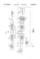
- FIG. 1is a block diagram of microwave power control apparatus in accordance with the present invention used to control the output energy of a linear accelerator;
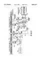
- FIG. 2is a schematic diagram of a preferred embodiment of the invention.
- FIG. 3Ais a graph of relative reflected power from the first accelerator guide section as a function of the difference in positions of the variable shorts;
- FIG. 3Bis a graph of the phase of the RF power supplied to the second accelerator guide section as a function of the positions of the variable shorts when they are moved together;
- FIG. 4is a block diagram of microwave control apparatus in accordance with the present invention used to control a phased array radar transmitter.
- FIG. 1A block diagram of a linear accelerator system incorporating an example of a microwave power control apparatus in accordance with the present invention is shown in FIG. 1.
- An electron linear accelerator 10includes an electron source 12, a first accelerator guide section 14 and a second accelerator guide section 16. Electrons generated by source 12 are accelerated in accelerator guide section 14 and are further accelerated in accelerator guide section 16 to produce an electron beam 20 having an output energy that is adjustable, typically over a range of a few million electron volts (MEV) to about 30 MEV for radiotherapy applications. In some cases, the second accelerator guide section 16 may decelerate the electrons received from accelerator guide section 14 to achieve the desired output energy.
- the construction of the linear accelerator 10is well known to those skilled in the art.
- Electrons passing through the accelerator guide sections 14 and 16are accelerated or decelerated by microwave fields applied to accelerator guide sections 14 and 16 by microwave power control apparatus 30.
- An RF source 32supplies RF power to a first port 34 of a symmetric hybrid junction 36.
- the RF source 32may be any suitable RF source, but is typically a magnetron oscillator or a klystron oscillator.
- microwave and RFare used interchangeably herein to refer to high frequency electromagnetic energy.
- a third port 38 of symmetric hybrid junction 36is connected to a dummy load 40.
- a second port 42 of symmetric hybrid junction 36is coupled to a microwave input 43 of first accelerator guide section 14, and a fourth port 44 of symmetric hybrid junction 36 is coupled to a first port 50 of a second symmetric hybrid junction 52.
- a third port 54 of symmetric hybrid junction 52is coupled to a microwave input 53 of second accelerator guide section 16.
- a fourth port 56 of symmetric hybrid junction 52is coupled to a first variable short 58, and a second port 60 of symmetric hybrid junction 52 is coupled to a second variable short 62.
- the variable shorts 58 and 62are adjusted by a controller 66 to provide RF power of a desired amplitude and phase to accelerator guide section 16 as described below as to result in electron beam 20 passing through the Beam Window (see FIG. 2) in position at the end of accelerator guide section 16 where the window also seals electron linear accelerator 10 from atmospheric conditions, as is well known in the art.
- control apparatus 30permits the amplitude and phase of the RF power supplied to accelerator guide section 16 to be adjusted independently by appropriate adjustment of variable shorts 58 and 62.
- the variable shorts 58 and 62can be adjusted by controller 66 to change the amplitude of the RF power supplied to accelerator guide section 16 and to maintain a constant phase shift between the RE power supplied to accelerator guide sections 14 and 16.
- controller 66adjusts the phase difference between the RF voltage supplied to accelerator guide sections 14 and 16 is changed, and the amplitudes remain constant.
- the reflected poweris partly dissipated in dummy load 40, and the rest of the reflected power is dissipated in the high power RF load of the isolation device 68 connected between port 34 of symmetric hybrid junction 36 and RF source 32 (see FIG. 2).
- FIG. 2A schematic diagram of a preferred embodiment of the control apparatus of the present invention is shown in FIG. 2. Like elements in FIGS. 1 and 2 have the same reference numerals which are not all described in the discussion herein of FIG. 2.
- the embodiment of FIG. 2has generally the same construction as shown in FIG. 1 and described above.
- Second port 42 of symmetric hybrid junction 36is connected through a directional coupler 70 to the microwave input 43 of first accelerator guide section 14.
- Third port 54 of symmetric hybrid junction 52is connected through a directional coupler 72 to the microwave input 53 of second accelerator guide section 16.
- the variable shorts 58 and 62are adjusted by linear stepping motors 76 and 78 of controller 66 respectively.
- Isolation device 68such as a four port ferrite circulator, is connected between RF source 32 and first port 34 of symmetric hybrid junction 36.
- a high power RF load and a low power RF loadare connected to the other two ports of the four port circulator.
- the embodiment shown in FIG. 2is designed for operation at 9.3 GHz and controls the output energy of electrons passing through accelerator guide sections 14 and 16 in a range of 4 MEV to 13 MEV.
- the symmetric hybrid junctions 36 and 52are type 51924, manufactured by Waveline, Inc.; variable shorts 58 and 62 are type SRC-VS-1, manufactured by Schonberg Research Corp.; the linear stepping motors 76 and 78 are type K92211-P2, manufactured by Airpax; and the directional couplers 70 and 72 are type SRC-DC-1, manufactured by Schonberg Research Corp.
- the above components of the control apparatusare given by way of example only, and are not limiting as to the scope of the present invention.
- One factor in the selection of components for the control apparatusis the frequency of operation of the accelerator guides 14 and 16. Suitable microwave components are selected for the desired operating frequency.
- the control apparatus of the inventionis expected to operate at frequencies in the L, S, X and V bands.
- Input RF power to port 34 of symmetric hybrid junction 36is divided equally between ports 42 and 44.
- half of the input RF poweris supplied through directional coupler 70 to first accelerator guide section 14, and half of the input RF power is supplied through port 44 to port 50 of symmetric hybrid junction 52.
- the RF power received through port 50 by symmetric hybrid junction 52is divided equally between ports 56 and 60.
- half of the RF power received through port 50is supplied to variable short 58
- half of the RF power received through port 50is supplied to variable short 62.
- Variable shorts 58 and 62each comprise a short circuit which is movable along a length of waveguide by the respective linear stepping motors 76 and 78.
- the short circuitreflects input RF energy with a phase that depends on the position of the short circuit.
- variable short 58reflects RF power back into port 56 of symmetric hybrid junction 52
- variable short 62reflects RF power back into port 60 of symmetric hybrid junction 52.
- the RF power received by symmetric hybrid junction 52 through ports 60 and 56is combined and, depending on the relative phases at ports 60 and 56, is output through port 54 to accelerator guide section 16 and through port 50 to port 44 of symmetric hybrid junction 36.
- the relative proportions of RF power directed by symmetric hybrid junction 52 to accelerator guide section 16 and to port 44depends on the phase difference between the RF power at ports 56 and 60.
- the relative proportions of RF power dissipated in dummy load 40 and directed toward the RF source 32 (which is isolated by isolation device 68) through port 34 of symmetric hybrid junction 36depends on the phase shift and amplitudes of the backward and reflected power flow in ports 42 and 44.
- symmetric hybrid junction 52are used to control the microwave power supplied to accelerator guide sections. 14 and 16.
- the RF power supplied to accelerator guide section 14remains constant in amplitude and phase as the variable shorts 58 and 62 are controlled by the linear stepping motors 76 and 78.
- the amplitude of the RF power supplied through port 54 to accelerator guide section 16changes.
- the phase difference between the RF power supplied to accelerator guide sections 14 and 16changes and is compensated by adjustment of the other variable short so as to maintain a constant phase difference.
- variable shorts 58 and 62are adjusted by linear stepping motors 76 and 78 by equal increments in the same direction, the phase shift between the RF power applied to accelerator guide sections 14 and 16 changes.
- the amplitude of the RF power supplied to accelerator guide section 16remains constant as its phase is changed with respect to the RF power supplied to accelerator guide section 14.
- phase and amplitudecan be controlled independently by appropriate adjustment of variable shorts 58 and 62.
- an equivalent of the symmetric hybrid junctionmust divide input RF power between two output ports in the forward direction. In the reverse direction, RF power received through the output ports is directed to the two input ports, with the proportion directed to each port depending on the phase difference between the RF power at the output ports.
- An example of a suitable symmetric hybrid junctionis a topwall hybrid.
- An equivalent of the variable shortmust reflect RF energy with a controllable phase.
- FIG. 3Ais a graph of relative reflected power (Ref) from, accelerator guide section 14 to port 42 of symmetric hybrid junction 36 as a function of the difference (Delta) in the positions of the variable shorts 58 and 62 (curve 90).
- FIG. 3Bis a graph of the phase of the RF power supplied through port 54 of symmetric hybrid junction 52 to accelerator guide section 16 as a function of the positions (Delta) of the variable shorts 58 and 62 when they are moved together (curve 92).
- the controller 66may include a control unit (not shown) for controlling the stepping motors 76 and 78.
- the positions of variable shorts 58 and 62 to obtain selected energies of electron beam 20are determined empirically. The required positions are preprogrammed into the control unit. During operation, the stored positions to obtain a desired energy are selected and are used to actuate stepping motors 76 and 78.
- a cross checkmay be provided by monitoring the forward and reflected power applied to the second accelerator guide section 16. The ratio of forward to reflected power can be compared with high and low limits for each energy of operation. When the ratio is outside the limits, operation can be terminated as a protective interlock mechanism.
- FIG. 4A general block diagram of the microwave power control apparatus of the present invention is shown in FIG. 4. Like elements in FIGS. 1 and 4 have the same reference numerals which are not all described in the discussion herein of FIG. 4.
- the microwave power control apparatusis used for supplying RF power to a first load 100 and a second load 102.
- second port 42 of symmetric hybrid junction 36supplies RF power to load 100
- third port 54 of symmetric hybrid junction 52supplies RF power to load 102.
- the amplitude of the RF power supplied to load 102 and the phase shift between the RF power supplied to loads 100 and 102can be changed. Amplitude and phase can be controlled independently as described above.
- the loads 100 and 102can be antennas in a phased array radar system.
- the control apparatusis used to control the amplitude and phase of the RF power supplied to the antennas.
Landscapes
- Physics & Mathematics (AREA)
- Engineering & Computer Science (AREA)
- Plasma & Fusion (AREA)
- Spectroscopy & Molecular Physics (AREA)
- Particle Accelerators (AREA)
- Non-Reversible Transmitting Devices (AREA)
- Waveguide Switches, Polarizers, And Phase Shifters (AREA)
Abstract
Description
Claims (16)
Priority Applications (6)
| Application Number | Priority Date | Filing Date | Title |
|---|---|---|---|
| US08/390,122US5661377A (en) | 1995-02-17 | 1995-02-17 | Microwave power control apparatus for linear accelerator using hybrid junctions |
| JP52515396AJP3730259B2 (en) | 1995-02-17 | 1996-02-16 | Microwave power control for linear accelerators |
| DE69634598TDE69634598T2 (en) | 1995-02-17 | 1996-02-16 | MICROWAVE POWER CONTROL DEVICE FOR LINEAR ACCELERATORS |
| PCT/US1996/002095WO1996025836A1 (en) | 1995-02-17 | 1996-02-16 | Microwave power control apparatus for linear accelerator |
| RU97115557/06ARU2163060C2 (en) | 1995-02-17 | 1996-02-16 | Linear accelerator microwave radiation power control device |
| EP96906476AEP0811307B1 (en) | 1995-02-17 | 1996-02-16 | Microwave power control apparatus for linear accelerator |
Applications Claiming Priority (1)
| Application Number | Priority Date | Filing Date | Title |
|---|---|---|---|
| US08/390,122US5661377A (en) | 1995-02-17 | 1995-02-17 | Microwave power control apparatus for linear accelerator using hybrid junctions |
Publications (1)
| Publication Number | Publication Date |
|---|---|
| US5661377Atrue US5661377A (en) | 1997-08-26 |
Family
ID=23541156
Family Applications (1)
| Application Number | Title | Priority Date | Filing Date |
|---|---|---|---|
| US08/390,122Expired - LifetimeUS5661377A (en) | 1995-02-17 | 1995-02-17 | Microwave power control apparatus for linear accelerator using hybrid junctions |
Country Status (6)
| Country | Link |
|---|---|
| US (1) | US5661377A (en) |
| EP (1) | EP0811307B1 (en) |
| JP (1) | JP3730259B2 (en) |
| DE (1) | DE69634598T2 (en) |
| RU (1) | RU2163060C2 (en) |
| WO (1) | WO1996025836A1 (en) |
Cited By (52)
| Publication number | Priority date | Publication date | Assignee | Title |
|---|---|---|---|---|
| US6459762B1 (en)* | 2001-03-13 | 2002-10-01 | Ro Inventions I, Llc | Method for producing a range of therapeutic radiation energy levels |
| US20070041500A1 (en)* | 2005-07-23 | 2007-02-22 | Olivera Gustavo H | Radiation therapy imaging and delivery utilizing coordinated motion of gantry and couch |
| US20070041499A1 (en)* | 2005-07-22 | 2007-02-22 | Weiguo Lu | Method and system for evaluating quality assurance criteria in delivery of a treatment plan |
| US20070046401A1 (en)* | 2005-08-25 | 2007-03-01 | Meddaugh Gard E | Standing wave particle beam accelerator having a plurality of power inputs |
| US20070158539A1 (en)* | 2003-08-27 | 2007-07-12 | Scantech Holdings, Llc | Radiation system |
| US20080043910A1 (en)* | 2006-08-15 | 2008-02-21 | Tomotherapy Incorporated | Method and apparatus for stabilizing an energy source in a radiation delivery device |
| US7567694B2 (en) | 2005-07-22 | 2009-07-28 | Tomotherapy Incorporated | Method of placing constraints on a deformation map and system for implementing same |
| US7574251B2 (en) | 2005-07-22 | 2009-08-11 | Tomotherapy Incorporated | Method and system for adapting a radiation therapy treatment plan based on a biological model |
| US7609809B2 (en) | 2005-07-22 | 2009-10-27 | Tomo Therapy Incorporated | System and method of generating contour structures using a dose volume histogram |
| US7639853B2 (en) | 2005-07-22 | 2009-12-29 | Tomotherapy Incorporated | Method of and system for predicting dose delivery |
| US7639854B2 (en) | 2005-07-22 | 2009-12-29 | Tomotherapy Incorporated | Method and system for processing data relating to a radiation therapy treatment plan |
| US7643661B2 (en) | 2005-07-22 | 2010-01-05 | Tomo Therapy Incorporated | Method and system for evaluating delivered dose |
| US20100034355A1 (en)* | 2008-08-11 | 2010-02-11 | Langeveld Willem G J | Systems and Methods for Using An Intensity-Modulated X-Ray Source |
| US20100169134A1 (en)* | 2008-12-31 | 2010-07-01 | Microsoft Corporation | Fostering enterprise relationships |
| US7786823B2 (en) | 2006-06-26 | 2010-08-31 | Varian Medical Systems, Inc. | Power regulators |
| EP1941533A4 (en)* | 2005-09-30 | 2010-09-29 | Hazardscan Inc | Multi-energy cargo inspection system based on an electron accelerator |
| US7839972B2 (en) | 2005-07-22 | 2010-11-23 | Tomotherapy Incorporated | System and method of evaluating dose delivered by a radiation therapy system |
| WO2011011222A1 (en) | 2009-07-22 | 2011-01-27 | Intraop Medical Corporation | Method and system for electron beam applications |
| US20110112351A1 (en)* | 2005-07-22 | 2011-05-12 | Fordyce Ii Gerald D | Method and system for evaluating quality assurance criteria in delivery of a treatment plan |
| US7957507B2 (en) | 2005-02-28 | 2011-06-07 | Cadman Patrick F | Method and apparatus for modulating a radiation beam |
| US8183801B2 (en) | 2008-08-12 | 2012-05-22 | Varian Medical Systems, Inc. | Interlaced multi-energy radiation sources |
| US8229068B2 (en) | 2005-07-22 | 2012-07-24 | Tomotherapy Incorporated | System and method of detecting a breathing phase of a patient receiving radiation therapy |
| US8232535B2 (en) | 2005-05-10 | 2012-07-31 | Tomotherapy Incorporated | System and method of treating a patient with radiation therapy |
| US20120200238A1 (en)* | 2009-08-21 | 2012-08-09 | Thales | Microwave Device for Accelerating Electrons |
| US8644442B2 (en) | 2008-02-05 | 2014-02-04 | The Curators Of The University Of Missouri | Radioisotope production and treatment of solution of target material |
| US8666015B2 (en)* | 2001-05-08 | 2014-03-04 | The Curators Of The University Of Missouri | Method and apparatus for generating thermal neutrons using an electron accelerator |
| US8767917B2 (en) | 2005-07-22 | 2014-07-01 | Tomotherapy Incorpoated | System and method of delivering radiation therapy to a moving region of interest |
| US8837670B2 (en) | 2006-05-05 | 2014-09-16 | Rapiscan Systems, Inc. | Cargo inspection system |
| US9052264B2 (en) | 2010-02-03 | 2015-06-09 | Rapiscan Systems, Inc. | Scanning systems |
| US9052403B2 (en) | 2002-07-23 | 2015-06-09 | Rapiscan Systems, Inc. | Compact mobile cargo scanning system |
| US9218933B2 (en) | 2011-06-09 | 2015-12-22 | Rapidscan Systems, Inc. | Low-dose radiographic imaging system |
| US9223050B2 (en) | 2005-04-15 | 2015-12-29 | Rapiscan Systems, Inc. | X-ray imaging system having improved mobility |
| US9223049B2 (en) | 2002-07-23 | 2015-12-29 | Rapiscan Systems, Inc. | Cargo scanning system with boom structure |
| US9224573B2 (en) | 2011-06-09 | 2015-12-29 | Rapiscan Systems, Inc. | System and method for X-ray source weight reduction |
| US9274065B2 (en) | 2012-02-08 | 2016-03-01 | Rapiscan Systems, Inc. | High-speed security inspection system |
| US9285498B2 (en) | 2003-06-20 | 2016-03-15 | Rapiscan Systems, Inc. | Relocatable X-ray imaging system and method for inspecting commercial vehicles and cargo containers |
| US9332624B2 (en) | 2008-05-20 | 2016-05-03 | Rapiscan Systems, Inc. | Gantry scanner systems |
| US20160193481A1 (en)* | 2013-09-11 | 2016-07-07 | The Board Of Trustees Of The Leland Stanford Junior University | Methods and systems for rf power generation and distribution to facilitate rapid radiation therapies |
| US9435752B2 (en) | 2010-02-03 | 2016-09-06 | Rapiscan Systems, Inc. | Systems and methods for scanning objects |
| US9443633B2 (en) | 2013-02-26 | 2016-09-13 | Accuray Incorporated | Electromagnetically actuated multi-leaf collimator |
| CN106231773A (en)* | 2016-07-27 | 2016-12-14 | 广州华大生物科技有限公司 | Twin-guide system and relevant apparatus for irradiation processing |
| CN106455288A (en)* | 2016-10-28 | 2017-02-22 | 中广核中科海维科技发展有限公司 | Adjustable-energy electron linear accelerator |
| WO2017151763A1 (en) | 2016-03-01 | 2017-09-08 | Intraop Medical Corporation | Low energy electron beam radiation system that generates electron beams with precisely controlled and adjustable penetration depth useful for therapeutic applications |
| US9791590B2 (en) | 2013-01-31 | 2017-10-17 | Rapiscan Systems, Inc. | Portable security inspection system |
| US9854662B2 (en) | 2016-03-11 | 2017-12-26 | Varex Imaging Corporation | Hybrid linear accelerator with a broad range of regulated electron and X-ray beam parameters includes both standing wave and traveling wave linear sections for providing a multiple-energy high-efficiency electron beam or X-ray beam useful for security inspection, non-destructive testing, radiation therapy, and other applications |
| US10015874B2 (en) | 2016-03-11 | 2018-07-03 | Varex Imaging Corporation | Hybrid standing wave linear accelerators providing accelerated charged particles or radiation beams |
| WO2018204649A1 (en) | 2017-05-04 | 2018-11-08 | Intraop Medical Corporation | Machine vision alignment and positioning system for electron beam treatment systems |
| US10576303B2 (en) | 2013-09-11 | 2020-03-03 | The Board of Trsutees of the Leland Stanford Junior University | Methods and systems for beam intensity-modulation to facilitate rapid radiation therapies |
| US10754057B2 (en) | 2016-07-14 | 2020-08-25 | Rapiscan Systems, Inc. | Systems and methods for improving penetration of radiographic scanners |
| CN112911785A (en)* | 2020-12-30 | 2021-06-04 | 湖南华创医疗科技有限公司 | Microwave power adjusting device, accelerator comprising same and adjusting method thereof |
| US12387900B2 (en) | 2022-02-03 | 2025-08-12 | Rapiscan Holdings, Inc. | Systems and methods for real-time energy and dose monitoring of an X-ray linear accelerator |
| US12420116B2 (en) | 2019-09-14 | 2025-09-23 | Intraop Medical Corporation | Methods and systems for using and controlling higher dose rate ionizing radiation in short time intervals |
Families Citing this family (12)
| Publication number | Priority date | Publication date | Assignee | Title |
|---|---|---|---|---|
| CN101862449A (en) | 2000-06-19 | 2010-10-20 | 亨特免疫有限公司 | Be used for the treatment of oidiomycotic compositions and method |
| CN1997256B (en)* | 2005-12-31 | 2010-08-25 | 清华大学 | A high and low power X ray output device |
| CN101076218B (en)* | 2006-05-19 | 2011-05-11 | 清华大学 | Apparatus and method for generating different-energy X-ray and system for discriminating materials |
| CN101163372B (en)* | 2006-10-11 | 2010-05-12 | 清华大学 | Multi-energy frequency doubling particle accelerator and method thereof |
| WO2013090342A1 (en)* | 2011-12-12 | 2013-06-20 | Muons, Inc. | Method and apparatus for inexpensive radio frequency (rf) source based on 2-stage injection-locked magnetrons with a 3-db hybrid combiner for precise and rapid control of output power and phase |
| CN102612251B (en)* | 2012-03-13 | 2015-03-04 | 苏州爱因智能设备有限公司 | Double-microwave-source electronic linear accelerator |
| CN103152972A (en)* | 2013-02-06 | 2013-06-12 | 江苏海明医疗器械有限公司 | Feedback type microwave system of medical linear accelerator |
| CN104470192B (en)* | 2013-09-22 | 2017-03-29 | 同方威视技术股份有限公司 | Electron linear accelerator system |
| DE102014118224A1 (en)* | 2014-12-09 | 2016-06-09 | AMPAS GmbH | Particle accelerator for producing a gebunchten particle beam |
| US10693464B2 (en) | 2018-05-18 | 2020-06-23 | Varex Imaging Corporation | Configurable linear accelerator |
| US11318329B1 (en)* | 2021-07-19 | 2022-05-03 | Accuray Incorporated | Imaging and treatment beam energy modulation utilizing an energy adjuster |
| CN114464514B (en)* | 2021-11-18 | 2023-04-07 | 电子科技大学 | Frequency-locking phase-locking structure and magnetron structure formed by same |
Citations (9)
| Publication number | Priority date | Publication date | Assignee | Title |
|---|---|---|---|---|
| US2925522A (en)* | 1955-09-30 | 1960-02-16 | High Voltage Engineering Corp | Microwave linear accelerator circuit |
| US3147396A (en)* | 1960-04-27 | 1964-09-01 | David J Goerz | Method and apparatus for phasing a linear accelerator |
| US3202942A (en)* | 1962-02-28 | 1965-08-24 | Robert V Garver | Microwave power amplitude limiter |
| US3582790A (en)* | 1969-06-03 | 1971-06-01 | Adams Russel Co Inc | Hybrid coupler receiver for lossless signal combination |
| SU533163A1 (en)* | 1975-03-11 | 1977-06-05 | Предприятие П/Я М-5631 | The stabilization system of the high-frequency floor in the cavity |
| US4118653A (en)* | 1976-12-22 | 1978-10-03 | Varian Associates, Inc. | Variable energy highly efficient linear accelerator |
| US4162423A (en)* | 1976-12-14 | 1979-07-24 | C.G.R. Mev | Linear accelerators of charged particles |
| JPS62131601A (en)* | 1985-12-03 | 1987-06-13 | Japan Radio Co Ltd | Microwave reversible gain phase shift method |
| US5321271A (en)* | 1993-03-30 | 1994-06-14 | Intraop, Inc. | Intraoperative electron beam therapy system and facility |
Family Cites Families (5)
| Publication number | Priority date | Publication date | Assignee | Title |
|---|---|---|---|---|
| US2920228A (en)* | 1954-12-13 | 1960-01-05 | Univ Leland Stanford Junior | Variable output linear accelerator |
| US4122373A (en)* | 1975-02-03 | 1978-10-24 | Varian Associates, Inc. | Standing wave linear accelerator and input coupling |
| GB2147150B (en)* | 1983-09-26 | 1987-01-07 | Philips Electronic Associated | Hybrid junction |
| RU2004082C1 (en)* | 1991-07-04 | 1993-11-30 | Научно-исследовательский институт электрофизической аппаратуры им.Д.В.Ефремова | Accelerating voltage generator of linear induction accelerator |
| RU2019921C1 (en)* | 1992-01-09 | 1994-09-15 | Лев Георгиевич Суходолец | Multi-section linear microwave accelerator |
- 1995
- 1995-02-17USUS08/390,122patent/US5661377A/ennot_activeExpired - Lifetime
- 1996
- 1996-02-16RURU97115557/06Apatent/RU2163060C2/ennot_activeIP Right Cessation
- 1996-02-16EPEP96906476Apatent/EP0811307B1/ennot_activeExpired - Lifetime
- 1996-02-16JPJP52515396Apatent/JP3730259B2/ennot_activeExpired - Fee Related
- 1996-02-16DEDE69634598Tpatent/DE69634598T2/ennot_activeExpired - Lifetime
- 1996-02-16WOPCT/US1996/002095patent/WO1996025836A1/enactiveIP Right Grant
Patent Citations (9)
| Publication number | Priority date | Publication date | Assignee | Title |
|---|---|---|---|---|
| US2925522A (en)* | 1955-09-30 | 1960-02-16 | High Voltage Engineering Corp | Microwave linear accelerator circuit |
| US3147396A (en)* | 1960-04-27 | 1964-09-01 | David J Goerz | Method and apparatus for phasing a linear accelerator |
| US3202942A (en)* | 1962-02-28 | 1965-08-24 | Robert V Garver | Microwave power amplitude limiter |
| US3582790A (en)* | 1969-06-03 | 1971-06-01 | Adams Russel Co Inc | Hybrid coupler receiver for lossless signal combination |
| SU533163A1 (en)* | 1975-03-11 | 1977-06-05 | Предприятие П/Я М-5631 | The stabilization system of the high-frequency floor in the cavity |
| US4162423A (en)* | 1976-12-14 | 1979-07-24 | C.G.R. Mev | Linear accelerators of charged particles |
| US4118653A (en)* | 1976-12-22 | 1978-10-03 | Varian Associates, Inc. | Variable energy highly efficient linear accelerator |
| JPS62131601A (en)* | 1985-12-03 | 1987-06-13 | Japan Radio Co Ltd | Microwave reversible gain phase shift method |
| US5321271A (en)* | 1993-03-30 | 1994-06-14 | Intraop, Inc. | Intraoperative electron beam therapy system and facility |
Non-Patent Citations (12)
| Title |
|---|
| C. J. Karzmark, "Advances in Linear Accelerator Design for Radiotherapy", Med. Phys. vol. 11, No. 2, Mar./Apr. 1984, pp. 105-128. |
| C. J. Karzmark, Advances in Linear Accelerator Design for Radiotherapy , Med. Phys. vol. 11, No. 2, Mar./Apr. 1984, pp. 105 128.* |
| C. J. Karzmark, et al, "Microwave Accelerator Structures", Medical Electron Accelerators, McGraw-Hill, Inc., 1993, pp. 67-87. |
| C. J. Karzmark, et al, "Multi-X-Ray Energy Accelerators", Medical Electron Accelerators, McGraw-Hill, Inc., 1993, pp. 189-199. |
| C. J. Karzmark, et al, Microwave Accelerator Structures , Medical Electron Accelerators, McGraw Hill, Inc., 1993, pp. 67 87.* |
| C. J. Karzmark, et al, Multi X Ray Energy Accelerators , Medical Electron Accelerators, McGraw Hill, Inc., 1993, pp. 189 199.* |
| D. Goer, "Linear Accelerator, Medical", Encyclopedia of Medical Devices and Instrumentation, 1988, John Wiley & Sons, vol. 3, pp. 1772-1800. |
| D. Goer, Linear Accelerator, Medical , Encyclopedia of Medical Devices and Instrumentation, 1988, John Wiley & Sons, vol. 3, pp. 1772 1800.* |
| J. A. Purdy, et al, "Dual Energy X-Ray Beam Accelerators in Radiation Therapy: An Overview", Nuclear Instruments and Methods in Physics Research, B 10/11, 1985, pp. 1090-1095. |
| J. A. Purdy, et al, Dual Energy X Ray Beam Accelerators in Radiation Therapy: An Overview , Nuclear Instruments and Methods in Physics Research, B 10/11, 1985, pp. 1090 1095.* |
| V. A. Vaguine, "Electron Linear Accelerator Structures and Design for Radiation Therapy Machines", IEEE Conf. Application of Accelerators in Research and Industry, Denton, Texas, Nov. 5, 1980, pp. 1-5. |
| V. A. Vaguine, Electron Linear Accelerator Structures and Design for Radiation Therapy Machines , IEEE Conf. Application of Accelerators in Research and Industry, Denton, Texas, Nov. 5, 1980, pp. 1 5.* |
Cited By (85)
| Publication number | Priority date | Publication date | Assignee | Title |
|---|---|---|---|---|
| WO2002071919A3 (en)* | 2001-03-13 | 2002-11-21 | Ro Inv S I Llc | Method for producing a range of therapeutic radiation energy levels |
| US6459762B1 (en)* | 2001-03-13 | 2002-10-01 | Ro Inventions I, Llc | Method for producing a range of therapeutic radiation energy levels |
| US8666015B2 (en)* | 2001-05-08 | 2014-03-04 | The Curators Of The University Of Missouri | Method and apparatus for generating thermal neutrons using an electron accelerator |
| US9223049B2 (en) | 2002-07-23 | 2015-12-29 | Rapiscan Systems, Inc. | Cargo scanning system with boom structure |
| US9052403B2 (en) | 2002-07-23 | 2015-06-09 | Rapiscan Systems, Inc. | Compact mobile cargo scanning system |
| US10007019B2 (en) | 2002-07-23 | 2018-06-26 | Rapiscan Systems, Inc. | Compact mobile cargo scanning system |
| US10670769B2 (en) | 2002-07-23 | 2020-06-02 | Rapiscan Systems, Inc. | Compact mobile cargo scanning system |
| US9285498B2 (en) | 2003-06-20 | 2016-03-15 | Rapiscan Systems, Inc. | Relocatable X-ray imaging system and method for inspecting commercial vehicles and cargo containers |
| US7952304B2 (en)* | 2003-08-27 | 2011-05-31 | Zavadlsev Alexandre A | Radiation system |
| US20070158539A1 (en)* | 2003-08-27 | 2007-07-12 | Scantech Holdings, Llc | Radiation system |
| US7957507B2 (en) | 2005-02-28 | 2011-06-07 | Cadman Patrick F | Method and apparatus for modulating a radiation beam |
| US9223050B2 (en) | 2005-04-15 | 2015-12-29 | Rapiscan Systems, Inc. | X-ray imaging system having improved mobility |
| US8232535B2 (en) | 2005-05-10 | 2012-07-31 | Tomotherapy Incorporated | System and method of treating a patient with radiation therapy |
| US20110112351A1 (en)* | 2005-07-22 | 2011-05-12 | Fordyce Ii Gerald D | Method and system for evaluating quality assurance criteria in delivery of a treatment plan |
| US7574251B2 (en) | 2005-07-22 | 2009-08-11 | Tomotherapy Incorporated | Method and system for adapting a radiation therapy treatment plan based on a biological model |
| US20070041499A1 (en)* | 2005-07-22 | 2007-02-22 | Weiguo Lu | Method and system for evaluating quality assurance criteria in delivery of a treatment plan |
| US7773788B2 (en) | 2005-07-22 | 2010-08-10 | Tomotherapy Incorporated | Method and system for evaluating quality assurance criteria in delivery of a treatment plan |
| US8767917B2 (en) | 2005-07-22 | 2014-07-01 | Tomotherapy Incorpoated | System and method of delivering radiation therapy to a moving region of interest |
| US8442287B2 (en) | 2005-07-22 | 2013-05-14 | Tomotherapy Incorporated | Method and system for evaluating quality assurance criteria in delivery of a treatment plan |
| US7839972B2 (en) | 2005-07-22 | 2010-11-23 | Tomotherapy Incorporated | System and method of evaluating dose delivered by a radiation therapy system |
| US7643661B2 (en) | 2005-07-22 | 2010-01-05 | Tomo Therapy Incorporated | Method and system for evaluating delivered dose |
| US7639854B2 (en) | 2005-07-22 | 2009-12-29 | Tomotherapy Incorporated | Method and system for processing data relating to a radiation therapy treatment plan |
| US7567694B2 (en) | 2005-07-22 | 2009-07-28 | Tomotherapy Incorporated | Method of placing constraints on a deformation map and system for implementing same |
| US7639853B2 (en) | 2005-07-22 | 2009-12-29 | Tomotherapy Incorporated | Method of and system for predicting dose delivery |
| US7609809B2 (en) | 2005-07-22 | 2009-10-27 | Tomo Therapy Incorporated | System and method of generating contour structures using a dose volume histogram |
| US8229068B2 (en) | 2005-07-22 | 2012-07-24 | Tomotherapy Incorporated | System and method of detecting a breathing phase of a patient receiving radiation therapy |
| US20070041500A1 (en)* | 2005-07-23 | 2007-02-22 | Olivera Gustavo H | Radiation therapy imaging and delivery utilizing coordinated motion of gantry and couch |
| US9731148B2 (en) | 2005-07-23 | 2017-08-15 | Tomotherapy Incorporated | Radiation therapy imaging and delivery utilizing coordinated motion of gantry and couch |
| US7400094B2 (en)* | 2005-08-25 | 2008-07-15 | Varian Medical Systems Technologies, Inc. | Standing wave particle beam accelerator having a plurality of power inputs |
| US20070046401A1 (en)* | 2005-08-25 | 2007-03-01 | Meddaugh Gard E | Standing wave particle beam accelerator having a plurality of power inputs |
| EP1941533A4 (en)* | 2005-09-30 | 2010-09-29 | Hazardscan Inc | Multi-energy cargo inspection system based on an electron accelerator |
| US9279901B2 (en) | 2006-05-05 | 2016-03-08 | Rapiscan Systems, Inc. | Cargo inspection system |
| US8837670B2 (en) | 2006-05-05 | 2014-09-16 | Rapiscan Systems, Inc. | Cargo inspection system |
| US7786823B2 (en) | 2006-06-26 | 2010-08-31 | Varian Medical Systems, Inc. | Power regulators |
| US20080043910A1 (en)* | 2006-08-15 | 2008-02-21 | Tomotherapy Incorporated | Method and apparatus for stabilizing an energy source in a radiation delivery device |
| US8644442B2 (en) | 2008-02-05 | 2014-02-04 | The Curators Of The University Of Missouri | Radioisotope production and treatment of solution of target material |
| US9332624B2 (en) | 2008-05-20 | 2016-05-03 | Rapiscan Systems, Inc. | Gantry scanner systems |
| US10098214B2 (en) | 2008-05-20 | 2018-10-09 | Rapiscan Systems, Inc. | Detector support structures for gantry scanner systems |
| US8781067B2 (en) | 2008-08-11 | 2014-07-15 | Rapiscan Systems, Inc. | Systems and methods for using an intensity-modulated X-ray source |
| US8437448B2 (en) | 2008-08-11 | 2013-05-07 | Rapiscan Systems, Inc. | Systems and methods for using an intensity-modulated X-ray source |
| US20100034355A1 (en)* | 2008-08-11 | 2010-02-11 | Langeveld Willem G J | Systems and Methods for Using An Intensity-Modulated X-Ray Source |
| US8054937B2 (en) | 2008-08-11 | 2011-11-08 | Rapiscan Systems, Inc. | Systems and methods for using an intensity-modulated X-ray source |
| US8183801B2 (en) | 2008-08-12 | 2012-05-22 | Varian Medical Systems, Inc. | Interlaced multi-energy radiation sources |
| US8604723B2 (en) | 2008-08-12 | 2013-12-10 | Varian Medical Systems, Inc. | Interlaced multi-energy radiation sources |
| US20100169134A1 (en)* | 2008-12-31 | 2010-07-01 | Microsoft Corporation | Fostering enterprise relationships |
| WO2011011222A1 (en) | 2009-07-22 | 2011-01-27 | Intraop Medical Corporation | Method and system for electron beam applications |
| US20110017920A1 (en)* | 2009-07-22 | 2011-01-27 | Intraop Medical Corporation | Method and system for electron beam applications |
| US8269197B2 (en) | 2009-07-22 | 2012-09-18 | Intraop Medical Corporation | Method and system for electron beam applications |
| US8716958B2 (en)* | 2009-08-21 | 2014-05-06 | Thales | Microwave device for accelerating electrons |
| US20120200238A1 (en)* | 2009-08-21 | 2012-08-09 | Thales | Microwave Device for Accelerating Electrons |
| US9052264B2 (en) | 2010-02-03 | 2015-06-09 | Rapiscan Systems, Inc. | Scanning systems |
| US9435752B2 (en) | 2010-02-03 | 2016-09-06 | Rapiscan Systems, Inc. | Systems and methods for scanning objects |
| US9218933B2 (en) | 2011-06-09 | 2015-12-22 | Rapidscan Systems, Inc. | Low-dose radiographic imaging system |
| US9224573B2 (en) | 2011-06-09 | 2015-12-29 | Rapiscan Systems, Inc. | System and method for X-ray source weight reduction |
| US11852775B2 (en) | 2012-02-08 | 2023-12-26 | Rapiscan Systems, Inc. | High-speed security inspection system |
| US11561321B2 (en) | 2012-02-08 | 2023-01-24 | Rapiscan Systems, Inc. | High-speed security inspection system |
| US11119245B2 (en) | 2012-02-08 | 2021-09-14 | Rapiscan Systems, Inc. | High-speed security inspection system |
| US12169264B2 (en) | 2012-02-08 | 2024-12-17 | Rapiscan Systems, Inc. | High-speed security inspection system |
| US10698128B2 (en) | 2012-02-08 | 2020-06-30 | Rapiscan Systems, Inc. | High-speed security inspection system |
| US9274065B2 (en) | 2012-02-08 | 2016-03-01 | Rapiscan Systems, Inc. | High-speed security inspection system |
| US10317566B2 (en) | 2013-01-31 | 2019-06-11 | Rapiscan Systems, Inc. | Portable security inspection system |
| US9791590B2 (en) | 2013-01-31 | 2017-10-17 | Rapiscan Systems, Inc. | Portable security inspection system |
| US11550077B2 (en) | 2013-01-31 | 2023-01-10 | Rapiscan Systems, Inc. | Portable vehicle inspection portal with accompanying workstation |
| US9443633B2 (en) | 2013-02-26 | 2016-09-13 | Accuray Incorporated | Electromagnetically actuated multi-leaf collimator |
| US10485991B2 (en)* | 2013-09-11 | 2019-11-26 | The Board Of Trustees Of The Leland Stanford Junior University | Methods and systems for RF power generation and distribution to facilitate rapid radiation therapies |
| US10576303B2 (en) | 2013-09-11 | 2020-03-03 | The Board of Trsutees of the Leland Stanford Junior University | Methods and systems for beam intensity-modulation to facilitate rapid radiation therapies |
| US10806950B2 (en) | 2013-09-11 | 2020-10-20 | The Board Of Trustees Of The Leland Stanford Junior University | Rapid imaging systems and methods for facilitating rapid radiation therapies |
| US20160193481A1 (en)* | 2013-09-11 | 2016-07-07 | The Board Of Trustees Of The Leland Stanford Junior University | Methods and systems for rf power generation and distribution to facilitate rapid radiation therapies |
| US11285341B2 (en) | 2016-03-01 | 2022-03-29 | Intraop Medical Corporation | Low energy electron beam radiation system that generates electron beams with precisely controlled and adjustable penetration depth useful for therapeutic applications |
| US10485993B2 (en) | 2016-03-01 | 2019-11-26 | Intraop Medical Corporation | Low energy electron beam radiation system that generates electron beams with precisely controlled and adjustable penetration depth useful for therapeutic applications |
| WO2017151763A1 (en) | 2016-03-01 | 2017-09-08 | Intraop Medical Corporation | Low energy electron beam radiation system that generates electron beams with precisely controlled and adjustable penetration depth useful for therapeutic applications |
| EP3838344A1 (en) | 2016-03-01 | 2021-06-23 | Intraop Medical Corporation | Electron beam radiation system useful for therapeutic applications |
| US10015874B2 (en) | 2016-03-11 | 2018-07-03 | Varex Imaging Corporation | Hybrid standing wave linear accelerators providing accelerated charged particles or radiation beams |
| US9854662B2 (en) | 2016-03-11 | 2017-12-26 | Varex Imaging Corporation | Hybrid linear accelerator with a broad range of regulated electron and X-ray beam parameters includes both standing wave and traveling wave linear sections for providing a multiple-energy high-efficiency electron beam or X-ray beam useful for security inspection, non-destructive testing, radiation therapy, and other applications |
| EP3427553A4 (en)* | 2016-03-11 | 2019-11-06 | Varex Imaging Corporation | STATIONARY / PROGRESSIVE WAVE HYBRID LINEAR ACCELERATORS TO PROVIDE ACCELERATED CHARGED PARTICLES OR RADIATION BEAMS |
| US10754057B2 (en) | 2016-07-14 | 2020-08-25 | Rapiscan Systems, Inc. | Systems and methods for improving penetration of radiographic scanners |
| US11397276B2 (en) | 2016-07-14 | 2022-07-26 | Rapiscan Systems, Inc. | Systems and methods for improving penetration of radiographic scanners |
| CN106231773A (en)* | 2016-07-27 | 2016-12-14 | 广州华大生物科技有限公司 | Twin-guide system and relevant apparatus for irradiation processing |
| CN106231773B (en)* | 2016-07-27 | 2018-05-11 | 广州华大生物科技有限公司 | Double wave guiding systems and relevant apparatus for irradiation processing |
| CN106455288A (en)* | 2016-10-28 | 2017-02-22 | 中广核中科海维科技发展有限公司 | Adjustable-energy electron linear accelerator |
| US11135449B2 (en) | 2017-05-04 | 2021-10-05 | Intraop Medical Corporation | Machine vision alignment and positioning system for electron beam treatment systems |
| WO2018204649A1 (en) | 2017-05-04 | 2018-11-08 | Intraop Medical Corporation | Machine vision alignment and positioning system for electron beam treatment systems |
| US12420116B2 (en) | 2019-09-14 | 2025-09-23 | Intraop Medical Corporation | Methods and systems for using and controlling higher dose rate ionizing radiation in short time intervals |
| CN112911785A (en)* | 2020-12-30 | 2021-06-04 | 湖南华创医疗科技有限公司 | Microwave power adjusting device, accelerator comprising same and adjusting method thereof |
| US12387900B2 (en) | 2022-02-03 | 2025-08-12 | Rapiscan Holdings, Inc. | Systems and methods for real-time energy and dose monitoring of an X-ray linear accelerator |
Also Published As
| Publication number | Publication date |
|---|---|
| JP3730259B2 (en) | 2005-12-21 |
| DE69634598D1 (en) | 2005-05-19 |
| EP0811307A4 (en) | 1998-04-29 |
| WO1996025836A1 (en) | 1996-08-22 |
| JPH11500260A (en) | 1999-01-06 |
| RU2163060C2 (en) | 2001-02-10 |
| DE69634598T2 (en) | 2005-09-15 |
| EP0811307A1 (en) | 1997-12-10 |
| EP0811307B1 (en) | 2005-04-13 |
Similar Documents
| Publication | Publication Date | Title |
|---|---|---|
| US5661377A (en) | Microwave power control apparatus for linear accelerator using hybrid junctions | |
| US5744919A (en) | CW particle accelerator with low particle injection velocity | |
| EP3427553B1 (en) | Hybrid standing wave/traveling wave linear accelerators for providing accelerated charged particles or radiation beams and method with the same | |
| US4629938A (en) | Standing wave linear accelerator having non-resonant side cavity | |
| US5483122A (en) | Two-beam particle acceleration method and apparatus | |
| US6060833A (en) | Continuous rotating-wave electron beam accelerator | |
| US8339071B2 (en) | Particle accelerator having wide energy control range | |
| CA2660221A1 (en) | Method and apparatus for stabilizing an energy source in a radiation delivery device | |
| US20080100236A1 (en) | Multi-section particle accelerator with controlled beam current | |
| US10015874B2 (en) | Hybrid standing wave linear accelerators providing accelerated charged particles or radiation beams | |
| CN106455288A (en) | Adjustable-energy electron linear accelerator | |
| US5821694A (en) | Method and apparatus for varying accelerator beam output energy | |
| TW200815062A (en) | Method and apparatus for stabilizing an energy source in a radiation delivery device | |
| CN220570712U (en) | Electron linac for radiation therapy and radiation therapy apparatus | |
| CN118283909B (en) | Medical proton accelerator and radiotherapy system | |
| CN116939943B (en) | Electron linear accelerator and radiotherapy equipment for radiotherapy | |
| US5291145A (en) | Microwave processing equipment | |
| CN222706682U (en) | Energy-adjustable electron linear acceleration structure | |
| CN115134985B (en) | High-power microwave switch for FLASH radiotherapy and X-ray source | |
| Begin et al. | Portable linac using CW magnetron as power source | |
| Warner | Fundamentals of electron linacs | |
| CN115811825A (en) | Microwave source time-sharing multiplexing ray generation device and use method and application thereof | |
| Mondelaers et al. | Optimisation of the output performance of a high intensity linear electron accelerator | |
| CN115802579A (en) | Ray generating device, using method and application | |
| HK1204203B (en) | A system for linear acceleration of electron |
Legal Events
| Date | Code | Title | Description |
|---|---|---|---|
| AS | Assignment | Owner name:INTRAOP, INC., CALIFORNIA Free format text:ASSIGNMENT OF ASSIGNORS INTEREST;ASSIGNORS:MISHIN, ANDREY V.;SCHONBERG, RUSSELL G.;DERUYTER, HANK;REEL/FRAME:008130/0466 Effective date:19960806 | |
| AS | Assignment | Owner name:INTRAOP MEDICAL, INC., CALIFORNIA Free format text:CHANGE OF NAME;ASSIGNOR:INTRAOP, INC.;REEL/FRAME:008412/0116 Effective date:19961120 | |
| STCF | Information on status: patent grant | Free format text:PATENTED CASE | |
| CC | Certificate of correction | ||
| AS | Assignment | Owner name:PACIFIC REPUBLIC CAPITAL CORP, CALIFORNIA Free format text:ASSIGNMENT OF ASSIGNORS INTEREST;ASSIGNOR:INTRAOP MEDICAL, INC.;REEL/FRAME:009833/0336 Effective date:19990310 | |
| FPAY | Fee payment | Year of fee payment:4 | |
| AS | Assignment | Owner name:SILICON VALLEY BANK, CALIFORNIA Free format text:SECURITY AGREEMENT;ASSIGNOR:INTRAOP MEDICAL, INC.;REEL/FRAME:012631/0124 Effective date:20010705 | |
| AS | Assignment | Owner name:INTRAOP MEDICAL, INC., CALIFORNIA Free format text:RELEASE BY SECURED PARTY;ASSIGNOR:SILICON VALLEY BANK;REEL/FRAME:013699/0843 Effective date:20030123 | |
| FPAY | Fee payment | Year of fee payment:8 | |
| AS | Assignment | Owner name:REGENMACHER HOLDINGS LTD., FLORIDA Free format text:SECURITY AGREEMENT;ASSIGNOR:INTRAOP MEDICAL CORPORATION;REEL/FRAME:016536/0775 Effective date:20050831 Owner name:ABS SOS-PLUS PARTNERS LTD., FLORIDA Free format text:SECURITY AGREEMENT;ASSIGNOR:INTRAOP MEDICAL CORPORATION;REEL/FRAME:016536/0775 Effective date:20050831 | |
| AS | Assignment | Owner name:LACUNA VENTURE FUND LLLP, AS AGENT, COLORADO Free format text:INTELLECTUAL PROPERTY SECURITY AGREEMENT;ASSIGNOR:INTRAOP MEDICAL CORPORATION;REEL/FRAME:021838/0162 Effective date:20080930 | |
| FPAY | Fee payment | Year of fee payment:12 |