US5661245A - Force sensor assembly with integrated rigid, movable interface for transferring force to a responsive medium - Google Patents
Force sensor assembly with integrated rigid, movable interface for transferring force to a responsive mediumDownload PDFInfo
- Publication number
- US5661245A US5661245AUS08/501,821US50182195AUS5661245AUS 5661245 AUS5661245 AUS 5661245AUS 50182195 AUS50182195 AUS 50182195AUS 5661245 AUS5661245 AUS 5661245A
- Authority
- US
- United States
- Prior art keywords
- force
- sensor assembly
- retainer
- force sensor
- housing
- Prior art date
- Legal status (The legal status is an assumption and is not a legal conclusion. Google has not performed a legal analysis and makes no representation as to the accuracy of the status listed.)
- Expired - Lifetime
Links
- 239000007787solidSubstances0.000claimsabstractdescription32
- 239000000758substrateSubstances0.000claimsabstractdescription18
- 239000000919ceramicSubstances0.000claimsabstractdescription13
- 238000009826distributionMethods0.000claimsdescription20
- 238000004891communicationMethods0.000claimsdescription8
- 239000000463materialSubstances0.000claimsdescription7
- 238000000034methodMethods0.000claimsdescription7
- 229920003023plasticPolymers0.000claimsdescription7
- 239000004033plasticSubstances0.000claimsdescription7
- 229920001296polysiloxanePolymers0.000claimsdescription6
- 238000006073displacement reactionMethods0.000claimsdescription5
- 239000012528membraneSubstances0.000claimsdescription4
- 229920001971elastomerPolymers0.000claimsdescription3
- 239000000806elastomerSubstances0.000claimsdescription3
- XUIMIQQOPSSXEZ-UHFFFAOYSA-NSiliconChemical compound[Si]XUIMIQQOPSSXEZ-UHFFFAOYSA-N0.000claimsdescription2
- 239000004744fabricSubstances0.000claimsdescription2
- 229910052710siliconInorganic materials0.000claimsdescription2
- 239000010703siliconSubstances0.000claimsdescription2
- 230000005540biological transmissionEffects0.000claims13
- 150000001875compoundsChemical class0.000claims1
- 230000001143conditioned effectEffects0.000abstractdescription4
- 239000000243solutionSubstances0.000description31
- 238000013459approachMethods0.000description8
- 229920004738ULTEM®Polymers0.000description5
- 239000007789gasSubstances0.000description4
- 239000007788liquidSubstances0.000description4
- 230000000712assemblyEffects0.000description3
- 238000000429assemblyMethods0.000description3
- 238000001802infusionMethods0.000description3
- 238000002347injectionMethods0.000description3
- 239000007924injectionSubstances0.000description3
- 230000002572peristaltic effectEffects0.000description3
- 230000007423decreaseEffects0.000description2
- 230000000994depressogenic effectEffects0.000description2
- 229940082652electrolytes and nutrients iv solution used in parenteral administration of fluidsDrugs0.000description2
- 238000003780insertionMethods0.000description2
- 230000037431insertionEffects0.000description2
- 230000014759maintenance of locationEffects0.000description2
- 238000005259measurementMethods0.000description2
- 230000009467reductionEffects0.000description2
- 239000000126substanceSubstances0.000description2
- 238000009966trimmingMethods0.000description2
- 229910018404Al2 O3Inorganic materials0.000description1
- 229920002449FKMPolymers0.000description1
- 239000000853adhesiveSubstances0.000description1
- 230000001070adhesive effectEffects0.000description1
- PNEYBMLMFCGWSK-UHFFFAOYSA-Naluminium oxideInorganic materials[O-2].[O-2].[O-2].[Al+3].[Al+3]PNEYBMLMFCGWSK-UHFFFAOYSA-N0.000description1
- 238000009530blood pressure measurementMethods0.000description1
- 229910010293ceramic materialInorganic materials0.000description1
- 230000006835compressionEffects0.000description1
- 238000007906compressionMethods0.000description1
- 238000011109contaminationMethods0.000description1
- 230000008602contractionEffects0.000description1
- 230000008878couplingEffects0.000description1
- 238000010168coupling processMethods0.000description1
- 238000005859coupling reactionMethods0.000description1
- 238000013461designMethods0.000description1
- 229920006332epoxy adhesivePolymers0.000description1
- 238000000605extractionMethods0.000description1
- 230000036512infertilityEffects0.000description1
- 238000001746injection mouldingMethods0.000description1
- 238000001990intravenous administrationMethods0.000description1
- 230000007774longtermEffects0.000description1
- 230000007246mechanismEffects0.000description1
- 239000002184metalSubstances0.000description1
- 238000012986modificationMethods0.000description1
- 230000004048modificationEffects0.000description1
- 235000015097nutrientsNutrition0.000description1
- 230000001681protective effectEffects0.000description1
- 238000005086pumpingMethods0.000description1
- 239000004065semiconductorSubstances0.000description1
- 239000011343solid materialSubstances0.000description1
- 230000003068static effectEffects0.000description1
Images


Classifications
- G—PHYSICS
- G01—MEASURING; TESTING
- G01L—MEASURING FORCE, STRESS, TORQUE, WORK, MECHANICAL POWER, MECHANICAL EFFICIENCY, OR FLUID PRESSURE
- G01L19/00—Details of, or accessories for, apparatus for measuring steady or quasi-steady pressure of a fluent medium insofar as such details or accessories are not special to particular types of pressure gauges
- G01L19/14—Housings
- G01L19/148—Details about the circuit board integration, e.g. integrated with the diaphragm surface or encapsulation
- A—HUMAN NECESSITIES
- A61—MEDICAL OR VETERINARY SCIENCE; HYGIENE
- A61M—DEVICES FOR INTRODUCING MEDIA INTO, OR ONTO, THE BODY; DEVICES FOR TRANSDUCING BODY MEDIA OR FOR TAKING MEDIA FROM THE BODY; DEVICES FOR PRODUCING OR ENDING SLEEP OR STUPOR
- A61M5/00—Devices for bringing media into the body in a subcutaneous, intra-vascular or intramuscular way; Accessories therefor, e.g. filling or cleaning devices, arm-rests
- A61M5/14—Infusion devices, e.g. infusing by gravity; Blood infusion; Accessories therefor
- A61M5/168—Means for controlling media flow to the body or for metering media to the body, e.g. drip meters, counters ; Monitoring media flow to the body
- A61M5/16831—Monitoring, detecting, signalling or eliminating infusion flow anomalies
- A61M5/16854—Monitoring, detecting, signalling or eliminating infusion flow anomalies by monitoring line pressure
- G—PHYSICS
- G01—MEASURING; TESTING
- G01L—MEASURING FORCE, STRESS, TORQUE, WORK, MECHANICAL POWER, MECHANICAL EFFICIENCY, OR FLUID PRESSURE
- G01L1/00—Measuring force or stress, in general
- G01L1/02—Measuring force or stress, in general by hydraulic or pneumatic means
- G—PHYSICS
- G01—MEASURING; TESTING
- G01L—MEASURING FORCE, STRESS, TORQUE, WORK, MECHANICAL POWER, MECHANICAL EFFICIENCY, OR FLUID PRESSURE
- G01L19/00—Details of, or accessories for, apparatus for measuring steady or quasi-steady pressure of a fluent medium insofar as such details or accessories are not special to particular types of pressure gauges
- G01L19/0007—Fluidic connecting means
- G01L19/0038—Fluidic connecting means being part of the housing
- G—PHYSICS
- G01—MEASURING; TESTING
- G01L—MEASURING FORCE, STRESS, TORQUE, WORK, MECHANICAL POWER, MECHANICAL EFFICIENCY, OR FLUID PRESSURE
- G01L19/00—Details of, or accessories for, apparatus for measuring steady or quasi-steady pressure of a fluent medium insofar as such details or accessories are not special to particular types of pressure gauges
- G01L19/06—Means for preventing overload or deleterious influence of the measured medium on the measuring device or vice versa
- G01L19/0627—Protection against aggressive medium in general
- G01L19/0645—Protection against aggressive medium in general using isolation membranes, specially adapted for protection
- G—PHYSICS
- G01—MEASURING; TESTING
- G01L—MEASURING FORCE, STRESS, TORQUE, WORK, MECHANICAL POWER, MECHANICAL EFFICIENCY, OR FLUID PRESSURE
- G01L19/00—Details of, or accessories for, apparatus for measuring steady or quasi-steady pressure of a fluent medium insofar as such details or accessories are not special to particular types of pressure gauges
- G01L19/14—Housings
- G01L19/142—Multiple part housings
- G01L19/143—Two part housings
Definitions
- This inventionrelates to force sensor assemblies and more particularly relates to force sensor assemblies for measuring pressure in flexible tubing.
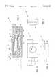
- FIG. 1labeled prior art, illustrates in cross-section an I.V. tube 102 compressively engaged between a solid surface 104 and a force sensor 106.
- One approach to measuring I.V. solution pressure within tube 102involves capturing and partially compressing I.V. tube 102 between force sensor 106 and solid surface 104.
- the force sensor 106detects a force on the tubal wall 108 corresponding to varying I.V. solution pressure exerted within tube 102.
- a force sensor output signal corresponding to the I.V. solution pressuremay be used to calculate, for example, I.V.
- FIG. 2labeled prior art, illustrates in a plan view another conventional approach ("bladder approach") to measuring I.V. solution pressure involving a bladder housing 200 (“bladder approach”) having flexible bladder 212 placed in series with I.V. tubes 204 and 208.
- bladder housing end 202connects to an I.V. tube 204 which is connected to a solution source (not shown), and bladder housing end 206 connects to an I.V. tube 208 which is connected to a solution destination (not shown).
- the bladder housing 200includes flexible pumping bladders 210 and 214. Bladders 210, 212, and 214 fill with I.V. solution as I.V. solution is pumped through the bladder housing 200.
- bladder housing 200having end regions positioned between solid surface 302, which is part of a pump housing, and pressure sensor 304.
- I.V. solutionfills the interior of bladder housing 200, and pump piston 312 impinges upon bladder 212.
- Bladder 212containing I.V. solution 314, transfers the pressure of the I.V. solution 314 to pressure sensor 304 through flexible bladder underside 316, protective membrane 308, and gel 310.
- Pressure sensor 304typically employs a piezoresistive silicon pressure sensor 306 which provides high reliability at a low cost.
- the tubing 204 and 208 and bladder housing 200must be disposable and periodically replaced which increase& the operating cost of the bladder approach. Additionally, the bladder approach requires a bladder housing 200 separate from the force sensor.
- the present inventionis directed to an economical force sensor assembly and a coupled solid interface that, in one embodiment, senses solution pressure in solutions transmitted via tubing.
- the force sensor assemblyincludes a pressure sensor housing having an integral solid interface for direct tubal impingement which avoids direct contact with tubal solution.
- the force sensor assembly pressure sensor housingutilizes a retainer having an opening to movably capture an integral solid interface structure.
- the solid interfaceincludes a flange positioned within the assembly below the retainer opening, and the flange dimensions are greater than the retainer opening to capture the solid interface structure within the assembly.
- the retaineris attached to the pressure sensor housing and separated from a gel-filled cavity underlying the retainer opening within the pressure sensor housing by a diaphragm on the gel.
- the geltransmits the force exerted on the diaphragm from the solid interface structure to a pressure sensor mounted at the base of the housing body cavity.
- a ceramic substrate having an integrated resistor networksupports the pressure sensor and an amplifier, and the pressure sensor and accompanying electronic components provide a conditioned electrical signal corresponding to the force applied to the solid interface structure.
- a force sensor assemblyhas a housing that includes a retainer and a cavity, the retainer having an opening in communication with the cavity.
- the force sensor assemblyfurther includes a pressure sensor at least partially disposed within the housing, a solid interface movably captured by the retainer and having a portion extending through the retainer opening away from the housing, and a pressure transmitter disposed within the cavity and in contact with the pressure sensor and the solid interface.
- FIG. 1labeled prior art, illustrates tubing compressed between a solid surface and a force sensor.
- FIG. 2labeled prior art, illustrates a bladder housing and connected tubing.
- FIG. 3labeled prior art, illustrates the bladder housing situated between a solid surface and a pressure sensor.
- FIG. 4illustrates a cross-sectional side view of a force sensor assembly with integrated plunger in accordance with the invention.
- FIG. 5illustrates a top view of the force sensor assembly of FIG. 4.
- FIG. 6illustrates a side view of the force sensor assembly of FIG. 4.
- FIG. 7illustrates a front view of the force sensor assembly of FIG. 4.
- FIG. 8illustrates a top view of an alternative force sensor assembly embodiment with mounting flanges.
- FIG. 9illustrates a side view of the force sensor assembly of FIG. 8.
- FIG. 10illustrates a side view of the force sensor assembly of FIG. 8 mounted to a solution dispensing control assembly and engaging a tube.
- FIG. 11illustrates a cross-sectional view of a force sensor assembly having flexible tabs for plunger snap insertion into a force sensor housing.
- FIG. 12illustrates a cross-sectional view of a force sensor assembly having a plunger within a housing directly impinging on a gel.
- FIG. 4illustrates a cross-sectional side view of a force sensor assembly 400 in one embodiment of the invention.
- the force sensor assembly housingconsists primarily of injection molded Ultem® plastic interface retainer 402 and injection molded Ultem® housing body 404. Ultem® is manufactured by G. E. Plastics, a Mount Vernon, Indiana company.
- the housing body 404includes a gel and electronic component cavity 406.
- Cavity 406has a 0.59 inch (15 mm) thick by 0.025 inch (0.64 mm) diameter cylindrical portion surrounding diaphragm 418.
- the diameter of cavity 406decreases to 0.445 inches (11.3 mm) and tapers to a 0.25 ⁇ 0.21 inch (6.35 ⁇ 5.33 mm) rectangular opening 430.
- the tapered portion 434 of cavity 406terminates with a 0.325 ⁇ 0.250 ⁇ 0.040 inch (8.26 ⁇ 6.35 ⁇ 1.02 mm) cavity portion.
- Ceramic substrate 408for example, an alumina (Al 2 O 3 96%) substrate, is recessed into plastic housing body 404 and attached with an epoxy adhesive.
- the ceramic substrate 408provides a boundary for cavity 406.
- the exposed underside of substrate 408beneficially allows laser trimming of an included conventional integrated trimmable resistor network (not shown) as needed to calibrate force sensor assembly 400.
- the substrate 408may be fabricated from a variety of ceramic and non-ceramic materials preferably having thermal expansion coefficients compatible with housing body 404.
- Metallic leads 410through thick film metal connections, electrically couple force sensor assembly 400 to external conventional electrical systems (not shown) such as a peristaltic pump or a syringe pump control system.
- micro-machined pressure sensor 412e.g. part no. P382A035SG from SenSym Inc., a Milpitas, Calif. company
- integrated circuit amplifier 414e.g., part no. LM324 from National Semiconductor Corp., a California company
- Ceramic substrate 408, pressure sensor 412, and amplifier 414form a well-known hybrid circuit for sensing pressure and providing a conditioned, calibrated output representing sensed pressure.
- Cavity 406is preferably filled with a gel 416, for example, silicone based gel such as deformable Sylgard 527 manufactured by Dow Corning Corp., a Midland, Mich. company.
- the 0.13 inch (0.330 mm) thick by 0.570 inch (14.5 mm) diameter interface diaphragm 418is preferably an elastomer, for example, a fabric reinforced Viton® membrane having a thickness of 0.13 inches (0.33 mm), that free floats on the surface of gel 416.
- diaphragm 418may free float to accommodate thermal expansion of gel 416, diaphragm 418 may be fastened to housing body 404 using, for example, clamps.
- diaphragm 418is less than the surrounding cavity 406 diameter, the viscosity of gel 416 forecloses leakage. Additionally, although force sensor assembly 400 interposes diaphragm 418 between gel 416 and plunger 420, plunger 420 may directly contact gel 416 by providing for example, a non-leaking seal between plunger 420 and retainer 402 or a close tolerance between plunger 420 and cavity 406 (FIG. 12).
- Ultem® plastic plunger 420preferably rests on diaphragm 418 but may alternatively be attached to diaphragm 418.
- Plunger 420includes a 0.020 inch (0.508 mm) thick by 0.365 inch (9.27 mm) diameter cylindrical diaphragm engagement portion 422, a 0.050 inch (1.27 mm) thick by 0.37 inch (9.4 mm) diameter cylindrical external interface portion 424, and a 0.017 inch (0.432 mm) thick by 0.485 inch (12.3 mm) diameter cylindrical flange portion 426 interposed between diaphragm portions 422 and 424.
- Retainer 402is fastened to body 404 preferably after filling cavity 406 with gel 416, placing diaphragm 418 on gel 416, and placing plunger 420 on diaphragm 418.
- Fastening retainer 402 to body 404involves using any suitable rigid attachment structure, for example, retainer 402 may be removably snapped to housing body 404 with hooks in retainer 402 (not shown) and corresponding indentions in housing body 404 (not shown). Alternatively, for example, retainer 402 may be permanently fastened to housing body 404 using an adhesive substance.
- Retainer 402 and housing body 404are preferably aligned using any suitable alignment structure, for example, inserting pins (not shown) in retainer 402 into corresponding holes (not shown) in housing body 404.
- retainer 402 and housing body 404are, for example, screwed together by providing corresponding threads.
- retainer 402may be fabricated as an integral feature of housing body 404.
- the retainer 402has a depth of 0.070 inches (1.78 mm) and includes a 0.020 inch (0.508 mm) thick retainer extension 428.
- Retainer extension 428is a lip that encircles plunger external interface portion 424 and defines a 0.420 inch (10.7 mm) diameter opening in retainer 402.
- Retainer relieved region 432has an inside diameter of 0.490 inches (12.5 mm).
- Retainer 402 in conjunction with retainer extension 428captures plunger 420 and retains plunger 420 within force sensor assembly 400 to form an integrated structure.
- This particular mechanical structure and its attachment methodsare illustrative and not limiting, equivalent structures and attachments may also be used.
- retainer 402not only retains plunger 420, retainer 402 also substantially prevents lateral displacement of plunger 420.
- plunger 420When depressed against gel 416 through diaphragm 418, plunger 420 creates force distributions within gel 416. Maintaining a consistent plunger lateral location provides consistent force distributions in gel 416 for a given plunger 420 depression and provides consistent corresponding force measurements. Failure to adequately restrict plunger 420 lateral displacement alters the force distribution in gel 416 which can result in inconsistent force measurements for a given plunger 420 depression.
- retainer 402preferably centers plunger 420 on diaphragm 418.
- a low tolerance between the inside diameter of retainer extension 428 of between 0 and approximately 0.006 inchesadequately maintains the lateral disposition of plunger 420.
- Integrating plunger 420 into the force sensor assembly 400advantageously allows calibration of force sensor assembly 400 as a unit prior to incorporating force sensor assembly 400 into a larger system.
- Calibration of force sensor assembly 400generally involves applying a known force to plunger external interface portion 424. This force depresses plunger 420 and creates force distributions within gel 416. The resulting data signals from pressure sensor 412 can be compared to the known force and the circuitry on substrate 408 is adjusted accordingly, for example, by laser trimming exposed resistors on substrate 408. The known force may be applied again to verify calibration.
- the calibrating forceis preferably applied to plunger 420 in a manner that generally simulates the expected force distribution within gel 416.
- a generally symmetric forceis applied to plunger 420 to simulate a generally symmetric force distribution representing a centered, impinging I.V. tube on plunger 420.
- the actual applied force locationmay vary from the calibrating force distribution, for example, the plunger 420 may be canted from an asymmetrical force application on plunger 420.
- a canted plunger 420could alter force distribution within gel 416 from force distribution resulting from an uncanted plunger 420, and force sensor assembly 412 could provide force information that differs from expected force information.
- a canted plunger 420can produce a force distribution in gel 416 that generally originates from the more depressed edge.
- the bottom edges of plunger 420may be chamfered to compensate for an I.V. tube impingement on plunger 420 that depresses plunger 420 into a canted position.
- the chamfered edgesprovide greater plunger 420 surface area contact with diaphragm 418 when canting plunger 420 which creates a force distribution within gel 416 that may more accurately represent the calibrating force sensor assembly 400 force distribution during plunger 420 canted conditions.
- force sensor assembly 400When utilized with a solution dispensing system, force sensor assembly 400 preferably does not directly contact the solution and, therefore, need not be periodically disposed for solution contamination reasons.
- FIG. 5illustrates a top view of the force sensor assembly 400.
- the external dimensions of force sensor assembly 400may be varied to accommodate connection and mounting features of devices incorporating force sensor assembly 400 such as peristaltic pump and syringe pump housings.
- the force sensor assembly 400has an overall length of 0.985 inches (25.53 mm), an overall width of 0.680 inches (17.27 mm), and a depth of 0.280 inches (7.11 mm).
- Leads 410have typical lengths of 0.260 inches (10.69 mm), widths of 0.025 inches, and depths of 0.025 inches.
- FIG. 6a side view of the force sensor assembly 400 is illustrated.
- Plunger 420is typically elevated 0.015 inches (0.38 mm) above retainer 402.
- the plunger 420 exposure depthwill vary depending on the expansion and contraction of gel 416 (FIG. 4).
- FIG. 7a front view of the force sensor assembly 400 is illustrated.
- FIG. 8illustrates a top view of force sensor assembly 800.
- a force sensor assembly 800may vary externally to comply with external considerations, for example, external mounting devices and varying environments, while retaining an integral solid interface.
- the internal configuration and components of force sensor assembly 800are identical to those of force sensor assembly 400; however, externally the force sensor assembly 800 configuration differs from force sensor assembly 400.
- Force sensor assembly 800includes opposing flanges 802 and 804 for securing force sensor assembly 800 to a pump door 1002 (FIG. 10).
- Flange 802includes holes 806 and 808, and flange 804 includes holes 810 and 812 for accommodating fastening devices such as screws or rivets.
- retainer 814is foreshortened opposite leads 410 corresponding to an opening (not shown) in door 1002 (FIG. 10).
- FIG. 9illustrates a side view of force sensor assembly 800 and, in hidden lines, retainer extension 428 which captures plunger 420. Additionally, housing body 902 is attached to retainer 814 in the same manner as the attachment of retainer 402 to housing body 404. Retainer 814 and housing body 902 are also fabricated by injection molding of Ultem® plastic.
- FIG. 10illustrates, in an illustrative application of force sensor assembly 800, a side view of the force sensor assembly 800 mounted to a door 1002 of a solution dispensing control assembly 1000.
- Plunger 420extends through an opening in pump door 1002.
- Leads 410connect to well-known data acquisition circuitry (not shown).
- a flexible tube 1004for example, an I.V. solution tube, extends through the solution dispensing control assembly 1000 and impinges on plunger 420 upon closure of pump door 1002.
- Tube 1004is compressed between plunger 420 and rigid surface 1006 and always exerts a force on plunger 420 when pump door 1002 is closed.
- the amount of force applied to plunger 420 by tube 1004corresponds to the compression of tube 1004 and to the pressure of solution within tube 1004.
- a rise in solution pressureincreases the impingement force of tube 1004 on plunger 420, and a solution pressure reduction decreases the impingement force of tube 1004 on plunger 420.
- Static solution pressure within tube 1004causes tube 1004 to exert a constant force on plunger 420.
- the force exerted on plunger 420causes plunger 420 to exert a force on diaphragm 418 which in turn exerts a force on gel 416.
- Gel 416converts the diaphragm 418 force exertion into a pressure exerted on pressure sensor 412.
- Pressure sensor 412provides an electronic signal corresponding to the detected force.
- Amplifier 414 and the integrated circuit network on ceramic substrate 408provide a conditioned signal to the data acquisition circuitry (not shown).
- FIG. 11illustrates a cross-sectional view of force sensor assembly 1100 having moveable tabs 1102 and 1104 that allow housing body 1108, in conjunction with an integral cylindrical retaining lip 1110, to retain plunger 1106.
- the moveable tabs 1102 and 1104contract to allow insertion of the lower portion of plunger 1106 into housing 1108 and expand within cavity 1118.
- the tabs 1102 and 1104remain substantially rigid when engaging the underside of retaining lip 1110 within cavity 1118 which prevents extraction of plunger 1106 from housing body 1108.
- the tabsmay be of any design which allows retention of plunger 1106 lower portion within housing 1108, for example, the tabs may be a flexible material or a spring loaded mechanism attached to the sidewall of plunger 1106. Additionally, additional tabs may be attached to the sidewall of plunger 1106.
- Housing 1108also includes diaphragm 1112, pressure sensor 1114, and gel 1116.
- An amplifier and accompanying circuitrymay be disposed within cavity 1116 and beneath pressure sensor 1114, respectively, substantially as shown in FIG. 4, the amplifier and accompanying circuitry may be coupled externally to the pressure sensor 1114, or the amplifier and accompanying circuitry may utilize a combination of external and internal coupling to the pressure sensor 1114 as will be evident to one of ordinary skill in the art after reading this description.
- the force sensor assemblyfunctions similarly and is made of similar materials as described in conjunction with force sensor assembly 400 (FIG. 4).
- FIG. 11also illustrates an alternative gel cavity 1120 configuration.
- FIG. 12illustrates a cross-sectional view of force sensor assembly 1200 having a plunger 1202 disposed within a housing 1204 that directly impinges on gel 1212.
- Plunger 1202includes flange 1206 positioned within a retainer cavity 1208.
- Retainer 1209may be an integral feature of housing 1204 with, for example, slots to allow passage of a correspondingly slotted flange 1206. A slight rotation of plunger 1202 prevents plunger 1202 escape from housing 1204 when the corresponding slots and flanges are used.
- retainer 1209may be a separate device and attached, as discussed in conjunction with retainer 402 (FIG. 4), to housing 1204 subsequent to positioning plunger 1202 in contact with gel 1212.
- Plunger 1202transmits forces applied to the plunger 1202 top to gel 1212.
- Pressure sensor 1214senses the corresponding pressure changes in gel 1212 and transmits pressure information in the form of an electronic output signal to circuitry such as, for example, amplifier 414 (FIG. 4), substrate 408 (FIG. 4), and leads 410 (FIG. 4), which, for example, amplify, filter, and temperature adjust the pressure sensor 1214 output signal.
- Force sensor assembly 1200is made of materials similar to those of force sensor assembly 400 (FIG. 4).
- the plungermay have various geometries that allow retention within a force sensor assembly and provide a solid interface.
- the plunger retainermay also have various geometries which effectively capture the plunger.
- the retainer extensionneed not be continuous to effectively capture the plunger.
- the arrangement of the pressure sensor and amplifiermay be varied, for example, the amplifier may be moved outside of the gel cavity.
- the force sensor assemblymay be used to measure both gas and liquid pressures.
- the force sensor assembly geometries, internally and externally,may be varied while continuing to incorporate an integrated solid interface.
- cavity 406may be filled with liquid, gas, solid materials, or a combination of liquid, gas, or solids to transmit force from the plunger 420 to the pressure sensor 412.
- the pressure sensor housingshould be sealed to prevent pressure transmitter leakage.
- the retainermay include a simple opening without an extension which captures the plunger in the same manner as the retainer extension. All dimensions herein are approximations.
- the force sensor assemblies of FIG. 4 and followingmay be made of any suitable materials. Accordingly, various other embodiments and modifications and improvements not described herein may be within the spirit and scope of the present invention, as defined by the following claims.
Landscapes
- General Physics & Mathematics (AREA)
- Physics & Mathematics (AREA)
- Health & Medical Sciences (AREA)
- Hematology (AREA)
- Biomedical Technology (AREA)
- Heart & Thoracic Surgery (AREA)
- Anesthesiology (AREA)
- Life Sciences & Earth Sciences (AREA)
- Animal Behavior & Ethology (AREA)
- General Health & Medical Sciences (AREA)
- Public Health (AREA)
- Veterinary Medicine (AREA)
- Engineering & Computer Science (AREA)
- Vascular Medicine (AREA)
- Measuring Fluid Pressure (AREA)
Abstract
Description
This invention relates to force sensor assemblies and more particularly relates to force sensor assemblies for measuring pressure in flexible tubing.
The acquisition of force data, often in the form of pressure measurement, is important for numerous applications. The automotive and medical industries utilize force sensor and pressure measuring systems to, for example, monitor and control a variety of substances and equipment. For example, in the medical industry precise and accurate information regarding the infusion into a patient of intravenous ("I.V.") solutions through I.V. tubing and of nutrients through tubing and a feeding pump can be critical to the patient's well being.
To properly control and monitor the infusion flow rate of I.V. solutions, force sensors may be positioned to measure the I.V. solution pressure. FIG. 1, labeled prior art, illustrates in cross-section an I.V.tube 102 compressively engaged between asolid surface 104 and aforce sensor 106. One approach to measuring I.V. solution pressure withintube 102 involves capturing and partially compressing I.V.tube 102 betweenforce sensor 106 andsolid surface 104. Theforce sensor 106 detects a force on thetubal wall 108 corresponding to varying I.V. solution pressure exerted withintube 102. A force sensor output signal corresponding to the I.V. solution pressure may be used to calculate, for example, I.V. solution flow rates or check for occlusions in the I.V. solution flow path. A variety of well known distribution systems, such as peristaltic pumps and syringe pumps, utilize force sensor acquired information to control and monitor the infusion of I.V. solutions. However, when used in pressure measuring applications,force sensor 106 is generally expensive and/or suffers from long term stability problems.
FIG. 2, labeled prior art, illustrates in a plan view another conventional approach ("bladder approach") to measuring I.V. solution pressure involving a bladder housing 200 ("bladder approach") havingflexible bladder 212 placed in series with I.V.tubes bladder housing end 202 connects to an I.V.tube 204 which is connected to a solution source (not shown), andbladder housing end 206 connects to an I.V.tube 208 which is connected to a solution destination (not shown). Thebladder housing 200 includesflexible pumping bladders bladder housing 200.
Referring to FIG. 3, labeled prior art, incross-section bladder housing 200 is illustrated having end regions positioned betweensolid surface 302, which is part of a pump housing, andpressure sensor 304. During operation, I.V. solution fills the interior ofbladder housing 200, andpump piston 312 impinges uponbladder 212.Bladder 212, containing I.V.solution 314, transfers the pressure of the I.V.solution 314 topressure sensor 304 throughflexible bladder underside 316,protective membrane 308, andgel 310.Pressure sensor 304 typically employs a piezoresistivesilicon pressure sensor 306 which provides high reliability at a low cost. However, to ensure sterility of the I.V. solution transported throughbladder housing 200, thetubing bladder housing 200 must be disposable and periodically replaced which increase& the operating cost of the bladder approach. Additionally, the bladder approach requires abladder housing 200 separate from the force sensor.
The present invention is directed to an economical force sensor assembly and a coupled solid interface that, in one embodiment, senses solution pressure in solutions transmitted via tubing. When used with a tubal solution distribution system, in another embodiment, the force sensor assembly includes a pressure sensor housing having an integral solid interface for direct tubal impingement which avoids direct contact with tubal solution.
In another embodiment the force sensor assembly pressure sensor housing utilizes a retainer having an opening to movably capture an integral solid interface structure. In this embodiment, the solid interface includes a flange positioned within the assembly below the retainer opening, and the flange dimensions are greater than the retainer opening to capture the solid interface structure within the assembly. The retainer is attached to the pressure sensor housing and separated from a gel-filled cavity underlying the retainer opening within the pressure sensor housing by a diaphragm on the gel. Furthermore, in this embodiment following force application to the solid interface structure, the gel transmits the force exerted on the diaphragm from the solid interface structure to a pressure sensor mounted at the base of the housing body cavity. In another embodiment, a ceramic substrate having an integrated resistor network supports the pressure sensor and an amplifier, and the pressure sensor and accompanying electronic components provide a conditioned electrical signal corresponding to the force applied to the solid interface structure.
In another embodiment a force sensor assembly has a housing that includes a retainer and a cavity, the retainer having an opening in communication with the cavity. The force sensor assembly further includes a pressure sensor at least partially disposed within the housing, a solid interface movably captured by the retainer and having a portion extending through the retainer opening away from the housing, and a pressure transmitter disposed within the cavity and in contact with the pressure sensor and the solid interface.
Reference numerals referring to the same feature appearing in multiple figures are the same.
FIG. 1, labeled prior art, illustrates tubing compressed between a solid surface and a force sensor.
FIG. 2, labeled prior art, illustrates a bladder housing and connected tubing.
FIG. 3, labeled prior art, illustrates the bladder housing situated between a solid surface and a pressure sensor.
FIG. 4 illustrates a cross-sectional side view of a force sensor assembly with integrated plunger in accordance with the invention.
FIG. 5 illustrates a top view of the force sensor assembly of FIG. 4.
FIG. 6 illustrates a side view of the force sensor assembly of FIG. 4.
FIG. 7 illustrates a front view of the force sensor assembly of FIG. 4.
FIG. 8 illustrates a top view of an alternative force sensor assembly embodiment with mounting flanges.
FIG. 9 illustrates a side view of the force sensor assembly of FIG. 8.
FIG. 10 illustrates a side view of the force sensor assembly of FIG. 8 mounted to a solution dispensing control assembly and engaging a tube.
FIG. 11 illustrates a cross-sectional view of a force sensor assembly having flexible tabs for plunger snap insertion into a force sensor housing.
FIG. 12 illustrates a cross-sectional view of a force sensor assembly having a plunger within a housing directly impinging on a gel.
The following description is intended to be illustrative only and not limiting.
FIG. 4 illustrates a cross-sectional side view of aforce sensor assembly 400 in one embodiment of the invention. The force sensor assembly housing consists primarily of injection molded Ultem®plastic interface retainer 402 and injection molded Ultem® housing body 404. Ultem® is manufactured by G. E. Plastics, a Mount Vernon, Indiana company. Thehousing body 404 includes a gel andelectronic component cavity 406.
Prior to attachingceramic substrate 408 tohousing body 404,micro-machined pressure sensor 412 e.g. part no. P382A035SG from SenSym Inc., a Milpitas, Calif. company, andintegrated circuit amplifier 414 e.g., part no. LM324 from National Semiconductor Corp., a California company, are conventionally mounted and electrically connected toceramic substrate 408.Ceramic substrate 408,pressure sensor 412, andamplifier 414 form a well-known hybrid circuit for sensing pressure and providing a conditioned, calibrated output representing sensed pressure.
Injection molded, Ultem®plastic plunger 420 preferably rests ondiaphragm 418 but may alternatively be attached todiaphragm 418.Plunger 420 includes a 0.020 inch (0.508 mm) thick by 0.365 inch (9.27 mm) diameter cylindricaldiaphragm engagement portion 422, a 0.050 inch (1.27 mm) thick by 0.37 inch (9.4 mm) diameter cylindricalexternal interface portion 424, and a 0.017 inch (0.432 mm) thick by 0.485 inch (12.3 mm) diametercylindrical flange portion 426 interposed betweendiaphragm portions
Theretainer 402 has a depth of 0.070 inches (1.78 mm) and includes a 0.020 inch (0.508 mm)thick retainer extension 428.Retainer extension 428 is a lip that encircles plungerexternal interface portion 424 and defines a 0.420 inch (10.7 mm) diameter opening inretainer 402. Retainer relievedregion 432 has an inside diameter of 0.490 inches (12.5 mm).Retainer 402 in conjunction withretainer extension 428 capturesplunger 420 and retainsplunger 420 withinforce sensor assembly 400 to form an integrated structure. This particular mechanical structure and its attachment methods are illustrative and not limiting, equivalent structures and attachments may also be used.
During operation,retainer 402 not only retainsplunger 420,retainer 402 also substantially prevents lateral displacement ofplunger 420. When depressed againstgel 416 throughdiaphragm 418,plunger 420 creates force distributions withingel 416. Maintaining a consistent plunger lateral location provides consistent force distributions ingel 416 for a givenplunger 420 depression and provides consistent corresponding force measurements. Failure to adequately restrictplunger 420 lateral displacement alters the force distribution ingel 416 which can result in inconsistent force measurements for a givenplunger 420 depression.
Referring to FIG. 4,retainer 402 preferably centersplunger 420 ondiaphragm 418. A low tolerance between the inside diameter ofretainer extension 428 of between 0 and approximately 0.006 inches adequately maintains the lateral disposition ofplunger 420.
Integratingplunger 420 into theforce sensor assembly 400 advantageously allows calibration offorce sensor assembly 400 as a unit prior to incorporatingforce sensor assembly 400 into a larger system. Calibration offorce sensor assembly 400 generally involves applying a known force to plungerexternal interface portion 424. This force depressesplunger 420 and creates force distributions withingel 416. The resulting data signals frompressure sensor 412 can be compared to the known force and the circuitry onsubstrate 408 is adjusted accordingly, for example, by laser trimming exposed resistors onsubstrate 408. The known force may be applied again to verify calibration.
Additionally, the calibrating force is preferably applied toplunger 420 in a manner that generally simulates the expected force distribution withingel 416. For example, a generally symmetric force is applied toplunger 420 to simulate a generally symmetric force distribution representing a centered, impinging I.V. tube onplunger 420.
During operation the actual applied force location may vary from the calibrating force distribution, for example, theplunger 420 may be canted from an asymmetrical force application onplunger 420. Acanted plunger 420 could alter force distribution withingel 416 from force distribution resulting from anuncanted plunger 420, and forcesensor assembly 412 could provide force information that differs from expected force information.
To provide a force distribution more representative of the calibrating force distribution when operating under variant conditions, various compensating approaches may be used to improvesensor assembly 400 accuracy. For example, acanted plunger 420 can produce a force distribution ingel 416 that generally originates from the more depressed edge. The bottom edges ofplunger 420 may be chamfered to compensate for an I.V. tube impingement onplunger 420 that depressesplunger 420 into a canted position. The chamfered edges providegreater plunger 420 surface area contact withdiaphragm 418 when cantingplunger 420 which creates a force distribution withingel 416 that may more accurately represent the calibratingforce sensor assembly 400 force distribution duringplunger 420 canted conditions.
When utilized with a solution dispensing system,force sensor assembly 400 preferably does not directly contact the solution and, therefore, need not be periodically disposed for solution contamination reasons.
FIG. 5 illustrates a top view of theforce sensor assembly 400. The external dimensions offorce sensor assembly 400 may be varied to accommodate connection and mounting features of devices incorporatingforce sensor assembly 400 such as peristaltic pump and syringe pump housings. Theforce sensor assembly 400 has an overall length of 0.985 inches (25.53 mm), an overall width of 0.680 inches (17.27 mm), and a depth of 0.280 inches (7.11 mm).Leads 410 have typical lengths of 0.260 inches (10.69 mm), widths of 0.025 inches, and depths of 0.025 inches.
Referring to FIG. 6, a side view of theforce sensor assembly 400 is illustrated.Plunger 420 is typically elevated 0.015 inches (0.38 mm) aboveretainer 402. Theplunger 420 exposure depth will vary depending on the expansion and contraction of gel 416 (FIG. 4).
Referring to FIG. 7, a front view of theforce sensor assembly 400 is illustrated.
FIG. 8 illustrates a top view offorce sensor assembly 800. FIG. 8 illustrates that aforce sensor assembly 800 may vary externally to comply with external considerations, for example, external mounting devices and varying environments, while retaining an integral solid interface. The internal configuration and components offorce sensor assembly 800 are identical to those offorce sensor assembly 400; however, externally theforce sensor assembly 800 configuration differs fromforce sensor assembly 400.Force sensor assembly 800 includes opposingflanges force sensor assembly 800 to a pump door 1002 (FIG. 10).Flange 802 includesholes flange 804 includesholes retainer 814 is foreshortened opposite leads 410 corresponding to an opening (not shown) in door 1002 (FIG. 10).
FIG. 9 illustrates a side view offorce sensor assembly 800 and, in hidden lines,retainer extension 428 which capturesplunger 420. Additionally,housing body 902 is attached toretainer 814 in the same manner as the attachment ofretainer 402 tohousing body 404.Retainer 814 andhousing body 902 are also fabricated by injection molding of Ultem® plastic.
FIG. 10 illustrates, in an illustrative application offorce sensor assembly 800, a side view of theforce sensor assembly 800 mounted to adoor 1002 of a solution dispensingcontrol assembly 1000.Plunger 420 extends through an opening inpump door 1002.Leads 410 connect to well-known data acquisition circuitry (not shown). Aflexible tube 1004, for example, an I.V. solution tube, extends through the solution dispensingcontrol assembly 1000 and impinges onplunger 420 upon closure ofpump door 1002.Tube 1004 is compressed betweenplunger 420 andrigid surface 1006 and always exerts a force onplunger 420 whenpump door 1002 is closed.
The amount of force applied toplunger 420 bytube 1004 corresponds to the compression oftube 1004 and to the pressure of solution withintube 1004. A rise in solution pressure increases the impingement force oftube 1004 onplunger 420, and a solution pressure reduction decreases the impingement force oftube 1004 onplunger 420. Static solution pressure withintube 1004 causestube 1004 to exert a constant force onplunger 420. The force exerted onplunger 420 causesplunger 420 to exert a force ondiaphragm 418 which in turn exerts a force ongel 416.Gel 416 converts thediaphragm 418 force exertion into a pressure exerted onpressure sensor 412.Pressure sensor 412 provides an electronic signal corresponding to the detected force.Amplifier 414 and the integrated circuit network onceramic substrate 408 provide a conditioned signal to the data acquisition circuitry (not shown).
FIG. 11 illustrates a cross-sectional view offorce sensor assembly 1100 havingmoveable tabs housing body 1108, in conjunction with an integralcylindrical retaining lip 1110, to retainplunger 1106. Themoveable tabs plunger 1106 intohousing 1108 and expand withincavity 1118. Thetabs lip 1110 withincavity 1118 which prevents extraction ofplunger 1106 fromhousing body 1108. The tabs may be of any design which allows retention ofplunger 1106 lower portion withinhousing 1108, for example, the tabs may be a flexible material or a spring loaded mechanism attached to the sidewall ofplunger 1106. Additionally, additional tabs may be attached to the sidewall ofplunger 1106.
FIG. 12 illustrates a cross-sectional view offorce sensor assembly 1200 having aplunger 1202 disposed within ahousing 1204 that directly impinges ongel 1212.Plunger 1202 includesflange 1206 positioned within aretainer cavity 1208.Retainer 1209 may be an integral feature ofhousing 1204 with, for example, slots to allow passage of a correspondingly slottedflange 1206. A slight rotation ofplunger 1202 preventsplunger 1202 escape fromhousing 1204 when the corresponding slots and flanges are used. Alternatively,retainer 1209 may be a separate device and attached, as discussed in conjunction with retainer 402 (FIG. 4), tohousing 1204 subsequent topositioning plunger 1202 in contact withgel 1212.
A close tolerance between the lower portion ofplunger 1202 andcavity 1210 sidewalls of approximately less than 0.010 inches (0.254 mm) and preferably as close to 0 inches (0 mm) as possible while allowinglateral plunger 1202 freedom of movement, allows direct contact betweenplunger 1202 andgel 1212 and preventsgel 1212 leakage. Additionally,higher gel 1212 viscosities allow tolerance reductions betweenplunger 1212 andcavity 1210 sidewalls while preventinggel 1212 leakage.
While the invention has been described with respect to the embodiments and variations set forth above, these embodiments and variations are illustrative and the invention is not to be considered limited in scope to these embodiments and variations. For example, the plunger may have various geometries that allow retention within a force sensor assembly and provide a solid interface. Accordingly, the plunger retainer may also have various geometries which effectively capture the plunger. Additionally, the retainer extension need not be continuous to effectively capture the plunger. Also, the arrangement of the pressure sensor and amplifier may be varied, for example, the amplifier may be moved outside of the gel cavity. Furthermore, the force sensor assembly may be used to measure both gas and liquid pressures. Additionally, the force sensor assembly geometries, internally and externally, may be varied while continuing to incorporate an integrated solid interface. Moreover,cavity 406 may be filled with liquid, gas, solid materials, or a combination of liquid, gas, or solids to transmit force from theplunger 420 to thepressure sensor 412. When low viscosity liquids or gases are used as pressure transmitters, the pressure sensor housing should be sealed to prevent pressure transmitter leakage. Also, the retainer may include a simple opening without an extension which captures the plunger in the same manner as the retainer extension. All dimensions herein are approximations. Furthermore, the force sensor assemblies of FIG. 4 and following may be made of any suitable materials. Accordingly, various other embodiments and modifications and improvements not described herein may be within the spirit and scope of the present invention, as defined by the following claims.
Claims (33)
1. A force sensor assembly comprising:
a housing having a retainer and a cavity, the retainer having an opening in communication with the cavity;
a pressure sensor at least partially disposed within the housing;
a rigid interface movably captured by the retainer and having a portion extending through the retainer opening away from the housing, the rigid interface portion extending through the retainer opening having a force receiving surface; and
a pressure transmitter filling the cavity and in contact with the pressure sensor and coupled to the rigid interface, the rigid interface having translational freedom to exert force, via the pressure transmitter, upon the pressure sensor corresponding to a force received on the force receiving surface of the rigid interface.
2. The force sensor assembly of claim 1 wherein the retainer is removably attached to the housing.
3. The force sensor assembly of claim 1 wherein the retainer opening has a diameter defined by an annular extension, and the rigid interface includes an annular flange disposed within the housing between the extension and the pressure transmitter, the flange having an outside diameter greater than the retainer opening diameter.
4. The force sensor assembly of claim 1 wherein the pressure transmitter includes a gel filling the cavity and in communication with and partially surrounding the pressure sensor, the force sensor assembly further includes:
a diaphragm interposed between the solid interface and the gel having a first surface in communication with the gel and a second opposing surface in contact with the rigid interface.
5. The force sensor assembly of claim 4 wherein the gel is a silicone based gel and the diaphragm is a fabric reinforced elastomer membrane.
6. The force sensor assembly of claim 4 wherein the diaphragm is free-floating.
7. The force sensor assembly of claim 1 further comprising:
an amplifier disposed within the cavity and electrically coupled to the pressure sensor.
8. The force sensor assembly of claim 1 wherein the housing includes a bottom surface comprised of a ceramic substrate, the ceramic substrate having a resistor network and a plurality of leads formed thereon, wherein the pressure sensor is mounted on the ceramic substrate.
9. The force sensor assembly of claim 1 wherein the retainer is removably attached to the housing.
10. The force sensor assembly of claim 1 wherein the pressure sensor is a micro-machined silicon pressure sensor.
11. The force sensor assembly of claim 1 wherein the rigid interface is a generally cylindrical plastic plunger.
12. The force sensor assembly of claim 1 wherein the housing is comprised of a rigid plastic.
13. A force sensor assembly for sensing externally applied force comprising:
a housing body having a first surface, a second surface, a first compartment, a second compartment in communication with the first compartment, and a third compartment in communication with the second compartment;
a platform coupled to the housing body first surface;
a pressure sensor disposed on the platform and in communication with the housing body third compartment;
a retainer body, coupled to the housing body second surface, and having an orifice opening to the housing body third compartment;
a pressure transmission material disposed in at least the second and third housing body compartments;
a diaphragm, disposed in the housing body first compartment, having a first surface in communication with the pressure transmission material and having a second surface opposite the first surface; and
a solid, rigid interface disposed through the retainer body orifice, the solid interface being movably captured by the retainer body, wherein the retainer body substantially restricts lateral displacement of the solid interface and permits captured, longitudinal movement, and the solid, rigid interface having a first surface to receive the externally applied force and a second surface in contact with the diaphragm second surface to exert force, corresponding to the externally applied force, through the diaphragm and the pressure transmission material to the pressure sensor.
14. The force sensor assembly as in claim 13 wherein the first compartment is cylindrical, the second compartment is a conical section tapering away from the first compartment and having a base diameter, the third compartment is a rectangular volume, and the first compartment has a diameter greater than the second compartment base diameter.
15. The force sensor assembly as in claim 13 wherein the diaphragm is free-floating.
16. The force sensor assembly as in claim 13 wherein the platform is a ceramic substrate having an integrated resistor network formed thereon.
17. The force sensor assembly as in claim 13 wherein the solid interface is a plunger having three cylindrical sections, and the retainer orifice is annular;
wherein the plunger first section has a diameter less than a diameter of the retainer orifice, is disposed within the orifice, and extends beyond the orifice away from the housing body;
wherein the plunger second section has a diameter greater than the retainer orifice diameter;
wherein the plunger third section has the surface in contact with the diaphragm; and
wherein the retainer orifice and the plunger are generally axially aligned.
18. The force sensor assembly as in claim 13 wherein the retainer orifice is defined by an annular continuous lip to longitudinally capture the solid interface.
19. The force sensor assembly as in claim 13 wherein the diaphragm is a cylindrical interface elastomer membrane.
20. The force sensor assembly as in claim 13 wherein the pressure transmission compound is a silicone based gel.
21. The force sensor assembly as in claim 13 wherein the pressure sensor is at least partially disposed in the housing body first compartment.
22. A method comprising the steps of:
retaining at least a portion of a rigid interface within a housing to substantially prevent lateral displacement of the rigid interface while allowing captured, longitudinal movement of the rigid interface;
applying a force to the rigid interface to translate the rigid interface;
generating a generally symmetric force distribution within a pressure transmission medium filling a chamber within the housing, wherein the generally symmetric force distribution corresponds to the force applied to the rigid interface;
transmitting a force corresponding to the force applied to the rigid interface, via the pressure transmission medium, to a pressure sensor disposed within the housing; and
providing an output from the pressure sensor corresponding to the applied force.
23. The force sensor assembly of claim 1 wherein the retainer substantially prevents lateral displacement of the rigid interface.
24. The force sensor assembly of claim 1 wherein the rigid interface is a plunger having chamfered edges to compensate for a nonuniform force application upon the plunger.
25. The force sensor assembly of claim 1 further comprising:
a solution dispensing control assembly having a flexible tube that impinges upon the rigid interface, wherein the flexible tube is capable of applying the force, corresponding to a pressure of a solution in the tube, which is received on the force receiving surface of the rigid interface.
26. The method of claim 22 further comprising the step of:
compensating for a nonsymmetrical force application in the force applying step.
27. The method as in claim 26 wherein the step of compensating further comprises the step of:
maintaining a generally consistent surface area contact of the rigid interface upon pressure transmission medium.
28. The method of claim 22 wherein the pressure transmission medium includes silicone based gel, and the step of transmitting comprises the step of:
distributing the applied force in the silicone based gel;
the method further comprising the step of:
sensing the applied force distributions in the silicone based gel with the pressure sensor.
29. The method of claim 22 wherein the step of transmitting comprises the step of:
transmitting the force applied to the rigid interface to the pressure transmission medium via a diaphragm disposed on a surface of the transmission medium.
30. A force sensor assembly for measuring a force applied through a flexible wall, the force sensor assembly comprising:
a housing having a cavity and a retainer;
a housing having a cavity and a retainer;
a pressure transmission solution filling the cavity;
a rigid interface captured by the retainer and having substantially restricted lateral freedom of movement, the interface having a rigid first surface to receive the force applied through the flexible wall, the interface further having a rigid second surface to provide a generally symmetric force distribution within the pressure transmission solution corresponding to the applied force; and
a pressure sensor in contact with the pressure transmission solution.
31. The force sensor assembly as in claim 30 wherein rigid interface includes chamfered edges to compensate for an asymmetrical application of force applied through the flexible wall.
32. The force sensor assembly as in claim 30 wherein the cavity includes a conical section tapering away from the rigid interface.
33. The force sensor assembly as in claim 30 further comprising:
a solution dispensing assembly having a tube impinging upon the rigid interface, wherein the tube includes the flexible wall.
Priority Applications (1)
| Application Number | Priority Date | Filing Date | Title |
|---|---|---|---|
| US08/501,821US5661245A (en) | 1995-07-14 | 1995-07-14 | Force sensor assembly with integrated rigid, movable interface for transferring force to a responsive medium |
Applications Claiming Priority (1)
| Application Number | Priority Date | Filing Date | Title |
|---|---|---|---|
| US08/501,821US5661245A (en) | 1995-07-14 | 1995-07-14 | Force sensor assembly with integrated rigid, movable interface for transferring force to a responsive medium |
Publications (1)
| Publication Number | Publication Date |
|---|---|
| US5661245Atrue US5661245A (en) | 1997-08-26 |
Family
ID=23995152
Family Applications (1)
| Application Number | Title | Priority Date | Filing Date |
|---|---|---|---|
| US08/501,821Expired - LifetimeUS5661245A (en) | 1995-07-14 | 1995-07-14 | Force sensor assembly with integrated rigid, movable interface for transferring force to a responsive medium |
Country Status (1)
| Country | Link |
|---|---|
| US (1) | US5661245A (en) |
Cited By (92)
| Publication number | Priority date | Publication date | Assignee | Title |
|---|---|---|---|---|
| US5808203A (en)* | 1997-05-12 | 1998-09-15 | Medrad, Inc. | Fluid pressure measurement devices |
| US5836886A (en)* | 1995-11-01 | 1998-11-17 | Kabushiki Kaisha Tokai Rika Denki Seisakusho | Catheter having a sensor |
| US5915281A (en)* | 1997-10-03 | 1999-06-22 | Delco Electronics Corporation | Silicon force and displacement sensor |
| US6089106A (en)* | 1998-09-04 | 2000-07-18 | Breed Automotive Technology, Inc. | Force sensor assembly |
| US6177727B1 (en)* | 1998-05-01 | 2001-01-23 | Motorola, Inc. | Saddle bracket for solid state pressure gauge |
| US6203759B1 (en) | 1996-05-31 | 2001-03-20 | Packard Instrument Company | Microvolume liquid handling system |
| US6347553B1 (en) | 2000-02-28 | 2002-02-19 | Alaris Medical Systems, Inc. | Force sensor assembly for an infusion pump |
| US6450038B1 (en)* | 1999-11-03 | 2002-09-17 | Gefran Sensori S.R.L. | High-precision pressure sensor |
| US6521187B1 (en) | 1996-05-31 | 2003-02-18 | Packard Instrument Company | Dispensing liquid drops onto porous brittle substrates |
| US6537817B1 (en) | 1993-05-31 | 2003-03-25 | Packard Instrument Company | Piezoelectric-drop-on-demand technology |
| DE20216822U1 (en)* | 2002-10-31 | 2003-08-14 | Keller AG für Druckmeßtechnik, Winterthur | Pressure transducer for indirect measurement of the liquid level in a tank, whereby the tank weight is transferred to the transducer via a pressure transfer medium, thus enabling precise measurements with an inexpensive device |
| US20030187370A1 (en)* | 2002-03-27 | 2003-10-02 | Kodama Roy K. | Uterine contraction sensing system and method |
| US20040074281A1 (en)* | 2002-10-16 | 2004-04-22 | Lobdell Donn D. | Testing of pressure sensor in surgical cassette |
| US20040074282A1 (en)* | 2002-10-16 | 2004-04-22 | Morgan Michael D. | Pressure sensing in surgical console |
| US6732592B1 (en) | 2001-10-31 | 2004-05-11 | Bgm Engineering, Inc. | Seat belt tension sensor package |
| US6782754B1 (en) | 2000-07-07 | 2004-08-31 | Rosemount, Inc. | Pressure transmitter for clean environments |
| US20040168521A1 (en)* | 2001-04-30 | 2004-09-02 | Martin Andersen | Method of mounting a sensor arrangement in a tubular member, and use of the method |
| US20040261534A1 (en)* | 2003-06-30 | 2004-12-30 | Mikhail Boukhny | Noninvasive pressure sensing assembly |
| US20060002799A1 (en)* | 2004-06-30 | 2006-01-05 | Millipore Corporation | Peristaltic pump comprising a bearing member and a counter-member adapted to cooperate with a tube |
| US20060010983A1 (en)* | 2004-07-16 | 2006-01-19 | Rosemount Inc. | Pressure transducer with external heater |
| US20060053895A1 (en)* | 2004-09-16 | 2006-03-16 | Infineon Technologies Ag | Pressure sensor apparatus and method of producing the same |
| EP1707931A1 (en) | 2005-03-31 | 2006-10-04 | STMicroelectronics S.r.l. | Analog data-input device provided with a microelectromechanical pressure sensor |
| US20060248957A1 (en)* | 2005-05-09 | 2006-11-09 | Vas Timothy A | Pressure transducer |
| US20060248958A1 (en)* | 2005-05-09 | 2006-11-09 | Betzner Timothy M | Pressure transducer for gaseous hydrogen environment |
| WO2007017301A1 (en)* | 2005-08-05 | 2007-02-15 | Robert Bosch Gmbh | Molded micromechanical force/pressure transducer, and corresponding production method |
| EP1762925A1 (en)* | 2005-09-09 | 2007-03-14 | STMicroelectronics S.r.l. | Analog input device with integrated pressure sensor and electronic apparatus equipped with said input device. |
| WO2007032032A1 (en)* | 2005-09-16 | 2007-03-22 | Stmicroelectronics S.R.L. | Pressure sensor having a high full-scale value with package thereof |
| US20070068922A1 (en)* | 2005-09-29 | 2007-03-29 | Westfield Brian L | Process fluid device temperature control |
| US20070251749A1 (en)* | 1995-06-07 | 2007-11-01 | Automotive Technologies International, Inc. | Vehicular Seats with Weight Sensing Capability |
| US20080042408A1 (en)* | 1995-06-07 | 2008-02-21 | Automotive Technologies International, Inc. | Vehicular Seats with Fluid-Containing Weight Sensing Sysem |
| US20080127743A1 (en)* | 2006-12-05 | 2008-06-05 | Werner Schadler | Force sensor |
| US20080189053A1 (en)* | 1995-06-07 | 2008-08-07 | Automotive Technologies International, Inc. | Apparatus and Method for Analyzing Weight of an Occupying Item of a Vehicular Seat |
| US20090114027A1 (en)* | 2007-11-06 | 2009-05-07 | Costin Sandu | Non-invasive system and method for measuring vacuum pressure in a fluid |
| US20090120195A1 (en)* | 2007-11-08 | 2009-05-14 | Willcox Charles R | Pressure sensor |
| CN100595541C (en)* | 2008-03-07 | 2010-03-24 | 合肥工业大学 | Air-floating Measuring Method of Force and Displacement |
| US20100160893A1 (en)* | 2008-12-23 | 2010-06-24 | Honeywell International Inc. | Method and system for measuring flow at patient utilizing differential force sensor |
| US7862521B1 (en) | 2002-03-27 | 2011-01-04 | Parker-Hannifin Corporation | Uterine contraction sensing system and method |
| US20110000313A1 (en)* | 2008-10-22 | 2011-01-06 | Honeywell International Inc. | Differential force sensor |
| US20110000318A1 (en)* | 2009-07-02 | 2011-01-06 | Honeywell International Inc. | Force sensor apparatus |
| CN101249569B (en)* | 2008-03-07 | 2011-03-16 | 合肥工业大学 | Air-float chief axis capable of independently measuring chief axis applied force and measurement method thereof |
| US20110107842A1 (en)* | 2008-04-18 | 2011-05-12 | Javad Dargahi | System for sensing and displaying softness and force |
| US8316725B2 (en) | 2010-12-15 | 2012-11-27 | Honeywell International Inc. | Force sensor |
| JP2013502949A (en)* | 2009-08-28 | 2013-01-31 | ハイブ・ディー・オー・オー | Medical pressure transducer and contact holder |
| WO2013115852A1 (en)* | 2012-02-01 | 2013-08-08 | Baxter Healthcare S.A. | Pressure sensing assembly for an infusion pump |
| EP2720017A1 (en)* | 2012-10-11 | 2014-04-16 | Honeywell International Inc. | Force sensor with mechanical over-force transfer mechanism |
| US8760637B2 (en) | 2010-08-30 | 2014-06-24 | Alcon Research, Ltd. | Optical sensing system including electronically switched optical magnification |
| US8806964B2 (en) | 2012-03-23 | 2014-08-19 | Honeywell International Inc. | Force sensor |
| US8858185B2 (en) | 2010-06-23 | 2014-10-14 | Hospira, Inc. | Fluid flow rate compensation system using an integrated conductivity sensor to monitor tubing changes |
| EP2837394A1 (en)* | 2009-08-18 | 2015-02-18 | CeQur SA | Medicine delivery device having detachable pressure sensing unit |
| US9003897B2 (en) | 2012-05-10 | 2015-04-14 | Honeywell International Inc. | Temperature compensated force sensor |
| US9003899B2 (en) | 2012-03-23 | 2015-04-14 | Honeywell International Inc. | Force sensor |
| US9022972B2 (en) | 2009-08-18 | 2015-05-05 | Cequr Sa | Medicine delivery device having detachable pressure sensing unit |
| WO2015149931A3 (en)* | 2014-04-02 | 2016-05-19 | Fresenius Medical Care Deutschland Gmbh | Method for sterilizing a measuring probe |
| WO2016182429A1 (en)* | 2015-05-08 | 2016-11-17 | Fugro Technology B.V. | Optical sensor device, sensor apparatus and cable comprising such device |
| US20170160163A1 (en)* | 2015-12-08 | 2017-06-08 | Empire Technology Development Llc | Sensor management based on surface type |
| JP2017187368A (en)* | 2016-04-05 | 2017-10-12 | 日本電産コパル電子株式会社 | Load sensor |
| NO20161579A1 (en)* | 2016-09-30 | 2018-04-02 | Spiro Medical As | Medical catheter for temperature and pressure sensing and production method thereof |
| US10022498B2 (en) | 2011-12-16 | 2018-07-17 | Icu Medical, Inc. | System for monitoring and delivering medication to a patient and method of using the same to minimize the risks associated with automated therapy |
| US10166328B2 (en) | 2013-05-29 | 2019-01-01 | Icu Medical, Inc. | Infusion system which utilizes one or more sensors and additional information to make an air determination regarding the infusion system |
| US10226565B2 (en)* | 2013-03-20 | 2019-03-12 | Fresenius Medical Care Deutschland Gmbh | Tube for extra-corporeal circuit with double connector |
| US10342917B2 (en) | 2014-02-28 | 2019-07-09 | Icu Medical, Inc. | Infusion system and method which utilizes dual wavelength optical air-in-line detection |
| US10430761B2 (en) | 2011-08-19 | 2019-10-01 | Icu Medical, Inc. | Systems and methods for a graphical interface including a graphical representation of medical data |
| US10463788B2 (en) | 2012-07-31 | 2019-11-05 | Icu Medical, Inc. | Patient care system for critical medications |
| US10549982B2 (en) | 2016-02-15 | 2020-02-04 | Stmicroelectronics S.R.L. | Pressure sensor encapsulated in elastomeric material, and system including the pressure sensor |
| US10578474B2 (en) | 2012-03-30 | 2020-03-03 | Icu Medical, Inc. | Air detection system and method for detecting air in a pump of an infusion system |
| US10596316B2 (en) | 2013-05-29 | 2020-03-24 | Icu Medical, Inc. | Infusion system and method of use which prevents over-saturation of an analog-to-digital converter |
| WO2020072234A1 (en)* | 2018-10-03 | 2020-04-09 | Baxalta GmbH | Detection assemblies for infusion pumps |
| US10635784B2 (en) | 2007-12-18 | 2020-04-28 | Icu Medical, Inc. | User interface improvements for medical devices |
| US10656894B2 (en) | 2017-12-27 | 2020-05-19 | Icu Medical, Inc. | Synchronized display of screen content on networked devices |
| US20200306447A1 (en)* | 2019-03-29 | 2020-10-01 | Honeywell International Inc. | Fluid flow sensor |
| US10850024B2 (en) | 2015-03-02 | 2020-12-01 | Icu Medical, Inc. | Infusion system, device, and method having advanced infusion features |
| US10874793B2 (en) | 2013-05-24 | 2020-12-29 | Icu Medical, Inc. | Multi-sensor infusion system for detecting air or an occlusion in the infusion system |
| US11135360B1 (en) | 2020-12-07 | 2021-10-05 | Icu Medical, Inc. | Concurrent infusion with common line auto flush |
| US11246985B2 (en) | 2016-05-13 | 2022-02-15 | Icu Medical, Inc. | Infusion pump system and method with common line auto flush |
| US11278671B2 (en) | 2019-12-04 | 2022-03-22 | Icu Medical, Inc. | Infusion pump with safety sequence keypad |
| US11324888B2 (en) | 2016-06-10 | 2022-05-10 | Icu Medical, Inc. | Acoustic flow sensor for continuous medication flow measurements and feedback control of infusion |
| US20220155171A1 (en)* | 2020-11-17 | 2022-05-19 | Robert Bosch Gmbh | Method for manufacturing a sensor and sensor |
| US11344668B2 (en) | 2014-12-19 | 2022-05-31 | Icu Medical, Inc. | Infusion system with concurrent TPN/insulin infusion |
| US11344673B2 (en) | 2014-05-29 | 2022-05-31 | Icu Medical, Inc. | Infusion system and pump with configurable closed loop delivery rate catch-up |
| US11406415B2 (en) | 2012-06-11 | 2022-08-09 | Tenex Health, Inc. | Systems and methods for tissue treatment |
| US11457937B2 (en) | 2014-09-02 | 2022-10-04 | Tenex Health, Inc. | Subcutaneous wound debridement |
| US20220373372A1 (en)* | 2021-05-19 | 2022-11-24 | Honeywell International Inc. | Fluid sensor for bubble and occlusion detection |
| US11517670B2 (en)* | 2019-05-10 | 2022-12-06 | Honeywell International Inc. | Fluid sensor |
| US11579028B2 (en) | 2017-10-17 | 2023-02-14 | Nextinput, Inc. | Temperature coefficient of offset compensation for force sensor and strain gauge |
| US11604104B2 (en) | 2017-02-09 | 2023-03-14 | Qorvo Us, Inc. | Integrated piezoresistive and piezoelectric fusion force sensor |
| US11609131B2 (en) | 2017-07-27 | 2023-03-21 | Qorvo Us, Inc. | Wafer bonded piezoresistive and piezoelectric force sensor and related methods of manufacture |
| RU2800893C2 (en)* | 2018-10-03 | 2023-07-31 | Такеда Фармасьютикал Компани Лимитед | Detector assembly for infusion pumps |
| US11874185B2 (en)* | 2017-11-16 | 2024-01-16 | Nextinput, Inc. | Force attenuator for force sensor |
| US11883361B2 (en) | 2020-07-21 | 2024-01-30 | Icu Medical, Inc. | Fluid transfer devices and methods of use |
| US11946817B2 (en) | 2017-02-09 | 2024-04-02 | DecaWave, Ltd. | Integrated digital force sensors and related methods of manufacture |
| US12350233B2 (en) | 2021-12-10 | 2025-07-08 | Icu Medical, Inc. | Medical fluid compounding systems with coordinated flow control |
| USD1091564S1 (en) | 2021-10-13 | 2025-09-02 | Icu Medical, Inc. | Display screen or portion thereof with graphical user interface for a medical device |
Citations (7)
| Publication number | Priority date | Publication date | Assignee | Title |
|---|---|---|---|---|
| US2488347A (en)* | 1945-09-12 | 1949-11-15 | Cox & Stevens Aireraft Corp | Electrical compression measuring device |
| US3439541A (en)* | 1967-06-09 | 1969-04-22 | North American Rockwell | Multi-range pressure measuring device |
| SU759876A1 (en)* | 1978-01-29 | 1980-08-30 | Boris Pivonenkov | Pressure sensor |
| US5209121A (en)* | 1990-07-24 | 1993-05-11 | Pfister Messtechnik Gmbh | Pressure sensor |
| US5218972A (en)* | 1988-04-29 | 1993-06-15 | Healthdyne, Inc. | Biomedical force measuring apparatus |
| US5392653A (en)* | 1992-06-03 | 1995-02-28 | Allergan, Inc. | Pressure transducer magnetically-coupled interface complementing minimal diaphragm movement during operation |
| US5438877A (en)* | 1994-06-13 | 1995-08-08 | Motorola, Inc. | Pressure sensor package for reducing stress-induced measurement error |
- 1995
- 1995-07-14USUS08/501,821patent/US5661245A/ennot_activeExpired - Lifetime
Patent Citations (7)
| Publication number | Priority date | Publication date | Assignee | Title |
|---|---|---|---|---|
| US2488347A (en)* | 1945-09-12 | 1949-11-15 | Cox & Stevens Aireraft Corp | Electrical compression measuring device |
| US3439541A (en)* | 1967-06-09 | 1969-04-22 | North American Rockwell | Multi-range pressure measuring device |
| SU759876A1 (en)* | 1978-01-29 | 1980-08-30 | Boris Pivonenkov | Pressure sensor |
| US5218972A (en)* | 1988-04-29 | 1993-06-15 | Healthdyne, Inc. | Biomedical force measuring apparatus |
| US5209121A (en)* | 1990-07-24 | 1993-05-11 | Pfister Messtechnik Gmbh | Pressure sensor |
| US5392653A (en)* | 1992-06-03 | 1995-02-28 | Allergan, Inc. | Pressure transducer magnetically-coupled interface complementing minimal diaphragm movement during operation |
| US5438877A (en)* | 1994-06-13 | 1995-08-08 | Motorola, Inc. | Pressure sensor package for reducing stress-induced measurement error |
Cited By (170)
| Publication number | Priority date | Publication date | Assignee | Title |
|---|---|---|---|---|
| US6537817B1 (en) | 1993-05-31 | 2003-03-25 | Packard Instrument Company | Piezoelectric-drop-on-demand technology |
| US20080189053A1 (en)* | 1995-06-07 | 2008-08-07 | Automotive Technologies International, Inc. | Apparatus and Method for Analyzing Weight of an Occupying Item of a Vehicular Seat |
| US7779956B2 (en)* | 1995-06-07 | 2010-08-24 | Automotive Technologies International, Inc.. | Vehicular seats with weight sensing capability |
| US7770920B2 (en) | 1995-06-07 | 2010-08-10 | Automotive Technologies International, Inc. | Vehicular seats with fluid-containing weight sensing system |
| US20070251749A1 (en)* | 1995-06-07 | 2007-11-01 | Automotive Technologies International, Inc. | Vehicular Seats with Weight Sensing Capability |
| US20080042408A1 (en)* | 1995-06-07 | 2008-02-21 | Automotive Technologies International, Inc. | Vehicular Seats with Fluid-Containing Weight Sensing Sysem |
| US5836886A (en)* | 1995-11-01 | 1998-11-17 | Kabushiki Kaisha Tokai Rika Denki Seisakusho | Catheter having a sensor |
| US6203759B1 (en) | 1996-05-31 | 2001-03-20 | Packard Instrument Company | Microvolume liquid handling system |
| US6422431B2 (en) | 1996-05-31 | 2002-07-23 | Packard Instrument Company, Inc. | Microvolume liquid handling system |
| US6521187B1 (en) | 1996-05-31 | 2003-02-18 | Packard Instrument Company | Dispensing liquid drops onto porous brittle substrates |
| US6592825B2 (en) | 1996-05-31 | 2003-07-15 | Packard Instrument Company, Inc. | Microvolume liquid handling system |
| US5808203A (en)* | 1997-05-12 | 1998-09-15 | Medrad, Inc. | Fluid pressure measurement devices |
| US5915281A (en)* | 1997-10-03 | 1999-06-22 | Delco Electronics Corporation | Silicon force and displacement sensor |
| US6177727B1 (en)* | 1998-05-01 | 2001-01-23 | Motorola, Inc. | Saddle bracket for solid state pressure gauge |
| EP1110068A1 (en)* | 1998-09-04 | 2001-06-27 | Breed Automotive Technology, Inc. | Force sensor assembly |
| US6089106A (en)* | 1998-09-04 | 2000-07-18 | Breed Automotive Technology, Inc. | Force sensor assembly |
| US6450038B1 (en)* | 1999-11-03 | 2002-09-17 | Gefran Sensori S.R.L. | High-precision pressure sensor |
| US6347553B1 (en) | 2000-02-28 | 2002-02-19 | Alaris Medical Systems, Inc. | Force sensor assembly for an infusion pump |
| US6782754B1 (en) | 2000-07-07 | 2004-08-31 | Rosemount, Inc. | Pressure transmitter for clean environments |
| US20040168521A1 (en)* | 2001-04-30 | 2004-09-02 | Martin Andersen | Method of mounting a sensor arrangement in a tubular member, and use of the method |
| US7024941B2 (en)* | 2001-04-30 | 2006-04-11 | Nkt Flexibles I/S | Method of mounting a sensor arrangement in a tubular member, and use of the method |
| US6732592B1 (en) | 2001-10-31 | 2004-05-11 | Bgm Engineering, Inc. | Seat belt tension sensor package |
| WO2003082112A1 (en)* | 2002-03-27 | 2003-10-09 | Ventrex, Inc. | Uterine contraction sensing system and method |
| US20030187370A1 (en)* | 2002-03-27 | 2003-10-02 | Kodama Roy K. | Uterine contraction sensing system and method |
| US7862521B1 (en) | 2002-03-27 | 2011-01-04 | Parker-Hannifin Corporation | Uterine contraction sensing system and method |
| US20040074281A1 (en)* | 2002-10-16 | 2004-04-22 | Lobdell Donn D. | Testing of pressure sensor in surgical cassette |
| US6955073B2 (en) | 2002-10-16 | 2005-10-18 | Alcon, Inc. | Pressure sensing in surgical console |
| US6868720B2 (en) | 2002-10-16 | 2005-03-22 | Alcon, Inc. | Testing of pressure sensor in surgical cassette |
| US20040074282A1 (en)* | 2002-10-16 | 2004-04-22 | Morgan Michael D. | Pressure sensing in surgical console |
| DE20216822U1 (en)* | 2002-10-31 | 2003-08-14 | Keller AG für Druckmeßtechnik, Winterthur | Pressure transducer for indirect measurement of the liquid level in a tank, whereby the tank weight is transferred to the transducer via a pressure transfer medium, thus enabling precise measurements with an inexpensive device |
| US6941813B2 (en) | 2003-06-30 | 2005-09-13 | Alcon, Inc. | Noninvasive pressure sensing assembly |
| US20040261534A1 (en)* | 2003-06-30 | 2004-12-30 | Mikhail Boukhny | Noninvasive pressure sensing assembly |
| US20060002799A1 (en)* | 2004-06-30 | 2006-01-05 | Millipore Corporation | Peristaltic pump comprising a bearing member and a counter-member adapted to cooperate with a tube |
| US7347099B2 (en) | 2004-07-16 | 2008-03-25 | Rosemount Inc. | Pressure transducer with external heater |
| US20060010983A1 (en)* | 2004-07-16 | 2006-01-19 | Rosemount Inc. | Pressure transducer with external heater |
| US7225678B2 (en)* | 2004-09-16 | 2007-06-05 | Infineon Technologies Ag | Housing structure of a pressure sensor apparatus and method of producing the same |
| US20060053895A1 (en)* | 2004-09-16 | 2006-03-16 | Infineon Technologies Ag | Pressure sensor apparatus and method of producing the same |
| US8044929B2 (en)* | 2005-03-31 | 2011-10-25 | Stmicroelectronics S.R.L. | Analog data-input device provided with a pressure sensor of a microelectromechanical type |
| US20060262088A1 (en)* | 2005-03-31 | 2006-11-23 | Stmicroelectronics S.R.L. | Analog data-input device provided with a pressure sensor of a microelectromechanical type |
| EP1707931A1 (en) | 2005-03-31 | 2006-10-04 | STMicroelectronics S.r.l. | Analog data-input device provided with a microelectromechanical pressure sensor |
| US7243552B2 (en) | 2005-05-09 | 2007-07-17 | Delphi Technologies, Inc. | Pressure sensor assembly |
| US7228744B2 (en) | 2005-05-09 | 2007-06-12 | Delphi Technologies, Inc. | Pressure transducer for gaseous hydrogen environment |
| EP1722209A1 (en)* | 2005-05-09 | 2006-11-15 | Delphi Technologies, Inc. | Pressure transducer for gaseous hydrogen environment |
| EP1722208A1 (en)* | 2005-05-09 | 2006-11-15 | Delphi Technologies, Inc. | Pressure transducer |
| US20060248958A1 (en)* | 2005-05-09 | 2006-11-09 | Betzner Timothy M | Pressure transducer for gaseous hydrogen environment |
| US20060248957A1 (en)* | 2005-05-09 | 2006-11-09 | Vas Timothy A | Pressure transducer |
| WO2007017301A1 (en)* | 2005-08-05 | 2007-02-15 | Robert Bosch Gmbh | Molded micromechanical force/pressure transducer, and corresponding production method |
| US20070068779A1 (en)* | 2005-09-09 | 2007-03-29 | Stmicroelectronics S.R.L. | Analog input device with integrated pressure sensor and electronic apparatus equipped with said input device |
| US7928960B2 (en)* | 2005-09-09 | 2011-04-19 | Stmicroelectronics S.R.L. | Analog input device with integrated pressure sensor and electronic apparatus equipped with said input device |
| EP1762925A1 (en)* | 2005-09-09 | 2007-03-14 | STMicroelectronics S.r.l. | Analog input device with integrated pressure sensor and electronic apparatus equipped with said input device. |
| WO2007032032A1 (en)* | 2005-09-16 | 2007-03-22 | Stmicroelectronics S.R.L. | Pressure sensor having a high full-scale value with package thereof |
| US20080223143A1 (en)* | 2005-09-16 | 2008-09-18 | Stmicroelectronics S.R.L. | Pressure sensor having a high full-scale value with package thereof |
| US8024977B2 (en) | 2005-09-16 | 2011-09-27 | Stmicroelectronics S.R.L. | Pressure sensor having a high full-scale value with package thereof |
| US7679033B2 (en) | 2005-09-29 | 2010-03-16 | Rosemount Inc. | Process field device temperature control |
| US20070068922A1 (en)* | 2005-09-29 | 2007-03-29 | Westfield Brian L | Process fluid device temperature control |
| US7559252B2 (en)* | 2006-12-05 | 2009-07-14 | Magna Powertrain Ag & Co Kg | Force sensor for the measurement of tensile force in a pulling means |
| US20080127743A1 (en)* | 2006-12-05 | 2008-06-05 | Werner Schadler | Force sensor |
| US20090114027A1 (en)* | 2007-11-06 | 2009-05-07 | Costin Sandu | Non-invasive system and method for measuring vacuum pressure in a fluid |
| US7845235B2 (en) | 2007-11-06 | 2010-12-07 | Costin Sandu | Non-invasive system and method for measuring vacuum pressure in a fluid |
| US20090120195A1 (en)* | 2007-11-08 | 2009-05-14 | Willcox Charles R | Pressure sensor |
| US7779698B2 (en) | 2007-11-08 | 2010-08-24 | Rosemount Inc. | Pressure sensor |
| US10635784B2 (en) | 2007-12-18 | 2020-04-28 | Icu Medical, Inc. | User interface improvements for medical devices |
| CN100595541C (en)* | 2008-03-07 | 2010-03-24 | 合肥工业大学 | Air-floating Measuring Method of Force and Displacement |
| CN101249569B (en)* | 2008-03-07 | 2011-03-16 | 合肥工业大学 | Air-float chief axis capable of independently measuring chief axis applied force and measurement method thereof |
| US8596111B2 (en)* | 2008-04-18 | 2013-12-03 | Concordia University | System for sensing and displaying softness and force |
| US20110107842A1 (en)* | 2008-04-18 | 2011-05-12 | Javad Dargahi | System for sensing and displaying softness and force |
| US20110000313A1 (en)* | 2008-10-22 | 2011-01-06 | Honeywell International Inc. | Differential force sensor |
| US8091436B2 (en) | 2008-10-22 | 2012-01-10 | Honeywell International Inc. | Differential force sensor |
| US20100274216A1 (en)* | 2008-12-23 | 2010-10-28 | Honeywell International Inc. | Method and system for measuring flow at patient utilizing differential force sensor |
| US8286505B2 (en) | 2008-12-23 | 2012-10-16 | Honeywell International Inc. | Method and system for measuring flow at patient utilizing differential force sensor |
| US7775127B2 (en)* | 2008-12-23 | 2010-08-17 | Honeywell International Inc. | Method and system for measuring flow at patient utilizing differential force sensor |
| US20100160893A1 (en)* | 2008-12-23 | 2010-06-24 | Honeywell International Inc. | Method and system for measuring flow at patient utilizing differential force sensor |
| US8327715B2 (en) | 2009-07-02 | 2012-12-11 | Honeywell International Inc. | Force sensor apparatus |
| US20110000318A1 (en)* | 2009-07-02 | 2011-01-06 | Honeywell International Inc. | Force sensor apparatus |
| EP2837394A1 (en)* | 2009-08-18 | 2015-02-18 | CeQur SA | Medicine delivery device having detachable pressure sensing unit |
| US10300196B2 (en) | 2009-08-18 | 2019-05-28 | Cequr Sa | Medicine delivery device having detachable pressure sensing unit |
| US9039654B2 (en) | 2009-08-18 | 2015-05-26 | Cequr Sa | Medicine delivery device having detachable pressure sensing unit |
| US9022972B2 (en) | 2009-08-18 | 2015-05-05 | Cequr Sa | Medicine delivery device having detachable pressure sensing unit |
| JP2013502949A (en)* | 2009-08-28 | 2013-01-31 | ハイブ・ディー・オー・オー | Medical pressure transducer and contact holder |
| US8858185B2 (en) | 2010-06-23 | 2014-10-14 | Hospira, Inc. | Fluid flow rate compensation system using an integrated conductivity sensor to monitor tubing changes |
| US8760637B2 (en) | 2010-08-30 | 2014-06-24 | Alcon Research, Ltd. | Optical sensing system including electronically switched optical magnification |
| US8316725B2 (en) | 2010-12-15 | 2012-11-27 | Honeywell International Inc. | Force sensor |
| US10430761B2 (en) | 2011-08-19 | 2019-10-01 | Icu Medical, Inc. | Systems and methods for a graphical interface including a graphical representation of medical data |
| US11599854B2 (en) | 2011-08-19 | 2023-03-07 | Icu Medical, Inc. | Systems and methods for a graphical interface including a graphical representation of medical data |
| US11004035B2 (en) | 2011-08-19 | 2021-05-11 | Icu Medical, Inc. | Systems and methods for a graphical interface including a graphical representation of medical data |
| US11972395B2 (en) | 2011-08-19 | 2024-04-30 | Icu Medical, Inc. | Systems and methods for a graphical interface including a graphical representation of medical data |
| US12346879B2 (en) | 2011-08-19 | 2025-07-01 | Icu Medical, Inc. | Systems and methods for a graphical interface including a graphical representation of medical data |
| US10022498B2 (en) | 2011-12-16 | 2018-07-17 | Icu Medical, Inc. | System for monitoring and delivering medication to a patient and method of using the same to minimize the risks associated with automated therapy |
| US11376361B2 (en) | 2011-12-16 | 2022-07-05 | Icu Medical, Inc. | System for monitoring and delivering medication to a patient and method of using the same to minimize the risks associated with automated therapy |
| WO2013115852A1 (en)* | 2012-02-01 | 2013-08-08 | Baxter Healthcare S.A. | Pressure sensing assembly for an infusion pump |
| GB2514068A (en)* | 2012-02-01 | 2014-11-12 | Baxter Healthcare Sa | Pressure sensing assembly for an infusion pump |
| GB2514068B (en)* | 2012-02-01 | 2018-08-29 | Baxter Healthcare Sa | Pressure sensing assembly for an infusion pump |
| US9003899B2 (en) | 2012-03-23 | 2015-04-14 | Honeywell International Inc. | Force sensor |
| US8806964B2 (en) | 2012-03-23 | 2014-08-19 | Honeywell International Inc. | Force sensor |
| US10578474B2 (en) | 2012-03-30 | 2020-03-03 | Icu Medical, Inc. | Air detection system and method for detecting air in a pump of an infusion system |
| US11933650B2 (en) | 2012-03-30 | 2024-03-19 | Icu Medical, Inc. | Air detection system and method for detecting air in a pump of an infusion system |
| US9003897B2 (en) | 2012-05-10 | 2015-04-14 | Honeywell International Inc. | Temperature compensated force sensor |
| US11406415B2 (en) | 2012-06-11 | 2022-08-09 | Tenex Health, Inc. | Systems and methods for tissue treatment |
| US11623042B2 (en) | 2012-07-31 | 2023-04-11 | Icu Medical, Inc. | Patient care system for critical medications |
| US12280239B2 (en) | 2012-07-31 | 2025-04-22 | Icu Medical, Inc. | Patient care system for critical medications |
| US10463788B2 (en) | 2012-07-31 | 2019-11-05 | Icu Medical, Inc. | Patient care system for critical medications |
| US9164003B2 (en)* | 2012-10-11 | 2015-10-20 | Honeywell International Inc. | Force sensor with mechanical over-force transfer mechanism |
| US20140102222A1 (en)* | 2012-10-11 | 2014-04-17 | Honeywell International Inc. | Force sensor with mechanical over-force transfer mechanism |
| CN103728068B (en)* | 2012-10-11 | 2018-09-18 | 霍尼韦尔国际公司 | The force snesor of excessive force transfer device with machinery |
| CN103728068A (en)* | 2012-10-11 | 2014-04-16 | 霍尼韦尔国际公司 | Force sensor with mechanical over-force transfer mechanism |
| AU2013231181B2 (en)* | 2012-10-11 | 2017-05-25 | Honeywell International, Inc. | Force sensor with mechanical over-force transfer mechanism |
| EP2720017A1 (en)* | 2012-10-11 | 2014-04-16 | Honeywell International Inc. | Force sensor with mechanical over-force transfer mechanism |
| AU2013231181C1 (en)* | 2012-10-11 | 2017-11-16 | Honeywell International, Inc. | Force sensor with mechanical over-force transfer mechanism |
| US10226565B2 (en)* | 2013-03-20 | 2019-03-12 | Fresenius Medical Care Deutschland Gmbh | Tube for extra-corporeal circuit with double connector |
| US10874793B2 (en) | 2013-05-24 | 2020-12-29 | Icu Medical, Inc. | Multi-sensor infusion system for detecting air or an occlusion in the infusion system |
| US12048831B2 (en) | 2013-05-24 | 2024-07-30 | Icu Medical, Inc. | Multi-sensor infusion system for detecting air or an occlusion in the infusion system |
| US10596316B2 (en) | 2013-05-29 | 2020-03-24 | Icu Medical, Inc. | Infusion system and method of use which prevents over-saturation of an analog-to-digital converter |
| US11596737B2 (en) | 2013-05-29 | 2023-03-07 | Icu Medical, Inc. | Infusion system and method of use which prevents over-saturation of an analog-to-digital converter |
| US11433177B2 (en) | 2013-05-29 | 2022-09-06 | Icu Medical, Inc. | Infusion system which utilizes one or more sensors and additional information to make an air determination regarding the infusion system |
| US12059551B2 (en) | 2013-05-29 | 2024-08-13 | Icu Medical, Inc. | Infusion system and method of use which prevents over-saturation of an analog-to-digital converter |
| US10166328B2 (en) | 2013-05-29 | 2019-01-01 | Icu Medical, Inc. | Infusion system which utilizes one or more sensors and additional information to make an air determination regarding the infusion system |
| US10342917B2 (en) | 2014-02-28 | 2019-07-09 | Icu Medical, Inc. | Infusion system and method which utilizes dual wavelength optical air-in-line detection |
| US12083310B2 (en) | 2014-02-28 | 2024-09-10 | Icu Medical, Inc. | Infusion system and method which utilizes dual wavelength optical air-in-line detection |
| WO2015149931A3 (en)* | 2014-04-02 | 2016-05-19 | Fresenius Medical Care Deutschland Gmbh | Method for sterilizing a measuring probe |
| US11344673B2 (en) | 2014-05-29 | 2022-05-31 | Icu Medical, Inc. | Infusion system and pump with configurable closed loop delivery rate catch-up |
| US11457937B2 (en) | 2014-09-02 | 2022-10-04 | Tenex Health, Inc. | Subcutaneous wound debridement |
| US11344668B2 (en) | 2014-12-19 | 2022-05-31 | Icu Medical, Inc. | Infusion system with concurrent TPN/insulin infusion |
| US10850024B2 (en) | 2015-03-02 | 2020-12-01 | Icu Medical, Inc. | Infusion system, device, and method having advanced infusion features |
| US12115337B2 (en) | 2015-03-02 | 2024-10-15 | Icu Medical, Inc. | Infusion system, device, and method having advanced infusion features |
| WO2016182429A1 (en)* | 2015-05-08 | 2016-11-17 | Fugro Technology B.V. | Optical sensor device, sensor apparatus and cable comprising such device |
| US10545166B2 (en) | 2015-05-08 | 2020-01-28 | Fugro Technology B.V. | Optical sensor device, sensor apparatus and cable comprising such device |
| US20180136250A1 (en)* | 2015-05-08 | 2018-05-17 | Fugro Technology B.V. | Optical sensor device, sensor apparatus and cable comprising such device |
| US20170160163A1 (en)* | 2015-12-08 | 2017-06-08 | Empire Technology Development Llc | Sensor management based on surface type |
| US10422714B2 (en)* | 2015-12-08 | 2019-09-24 | Empire Technology Development Llc | Sensor management based on surface type |
| US10549982B2 (en) | 2016-02-15 | 2020-02-04 | Stmicroelectronics S.R.L. | Pressure sensor encapsulated in elastomeric material, and system including the pressure sensor |
| US11254561B2 (en) | 2016-02-15 | 2022-02-22 | Stmicroelectronics S.R.L. | Pressure sensor encapsulated in elastomeric material, and system including the pressure sensor |
| JP2017187368A (en)* | 2016-04-05 | 2017-10-12 | 日本電産コパル電子株式会社 | Load sensor |
| US12201811B2 (en) | 2016-05-13 | 2025-01-21 | Icu Medical, Inc. | Infusion pump system and method with common line auto flush |
| US11246985B2 (en) | 2016-05-13 | 2022-02-15 | Icu Medical, Inc. | Infusion pump system and method with common line auto flush |
| US11324888B2 (en) | 2016-06-10 | 2022-05-10 | Icu Medical, Inc. | Acoustic flow sensor for continuous medication flow measurements and feedback control of infusion |
| US12076531B2 (en) | 2016-06-10 | 2024-09-03 | Icu Medical, Inc. | Acoustic flow sensor for continuous medication flow measurements and feedback control of infusion |
| NO344722B1 (en)* | 2016-09-30 | 2020-03-23 | Spiro Medical As | Medical catheter for temperature and pressure sensing and production method thereof |
| NO20161579A1 (en)* | 2016-09-30 | 2018-04-02 | Spiro Medical As | Medical catheter for temperature and pressure sensing and production method thereof |
| US11604104B2 (en) | 2017-02-09 | 2023-03-14 | Qorvo Us, Inc. | Integrated piezoresistive and piezoelectric fusion force sensor |
| US11808644B2 (en) | 2017-02-09 | 2023-11-07 | Qorvo Us, Inc. | Integrated piezoresistive and piezoelectric fusion force sensor |
| US11946817B2 (en) | 2017-02-09 | 2024-04-02 | DecaWave, Ltd. | Integrated digital force sensors and related methods of manufacture |
| US11609131B2 (en) | 2017-07-27 | 2023-03-21 | Qorvo Us, Inc. | Wafer bonded piezoresistive and piezoelectric force sensor and related methods of manufacture |
| US11946816B2 (en) | 2017-07-27 | 2024-04-02 | Nextinput, Inc. | Wafer bonded piezoresistive and piezoelectric force sensor and related methods of manufacture |
| US11898918B2 (en) | 2017-10-17 | 2024-02-13 | Nextinput, Inc. | Temperature coefficient of offset compensation for force sensor and strain gauge |
| US11579028B2 (en) | 2017-10-17 | 2023-02-14 | Nextinput, Inc. | Temperature coefficient of offset compensation for force sensor and strain gauge |
| US12203819B2 (en) | 2017-10-17 | 2025-01-21 | Nextinput, Inc. | Temperature coefficient of offset compensation for force sensor and strain gauge |
| US11874185B2 (en)* | 2017-11-16 | 2024-01-16 | Nextinput, Inc. | Force attenuator for force sensor |
| US11868161B2 (en) | 2017-12-27 | 2024-01-09 | Icu Medical, Inc. | Synchronized display of screen content on networked devices |
| US10656894B2 (en) | 2017-12-27 | 2020-05-19 | Icu Medical, Inc. | Synchronized display of screen content on networked devices |
| US12333201B2 (en) | 2017-12-27 | 2025-06-17 | Icu Medical, Inc. | Synchronized display of screen content on networked devices |
| US11029911B2 (en) | 2017-12-27 | 2021-06-08 | Icu Medical, Inc. | Synchronized display of screen content on networked devices |
| AU2019355801B2 (en)* | 2018-10-03 | 2025-05-15 | Takeda Pharmaceutical Company Limited | Detection assemblies for infusion pumps |
| RU2800893C2 (en)* | 2018-10-03 | 2023-07-31 | Такеда Фармасьютикал Компани Лимитед | Detector assembly for infusion pumps |
| WO2020072234A1 (en)* | 2018-10-03 | 2020-04-09 | Baxalta GmbH | Detection assemblies for infusion pumps |
| US11813431B2 (en)* | 2019-03-29 | 2023-11-14 | Honeywell International Inc. | Fluid flow sensor |
| US20200306447A1 (en)* | 2019-03-29 | 2020-10-01 | Honeywell International Inc. | Fluid flow sensor |
| US11517670B2 (en)* | 2019-05-10 | 2022-12-06 | Honeywell International Inc. | Fluid sensor |
| US11857760B2 (en) | 2019-05-10 | 2024-01-02 | Honeywell International Inc. | Fluid sensor |
| US12268843B2 (en) | 2019-12-04 | 2025-04-08 | Icu Medical, Inc. | Infusion pump with safety sequence keypad |
| US11278671B2 (en) | 2019-12-04 | 2022-03-22 | Icu Medical, Inc. | Infusion pump with safety sequence keypad |
| US11883361B2 (en) | 2020-07-21 | 2024-01-30 | Icu Medical, Inc. | Fluid transfer devices and methods of use |
| US12310921B2 (en) | 2020-07-21 | 2025-05-27 | Icu Medical, Inc. | Fluid transfer devices and methods of use |
| US11841283B2 (en)* | 2020-11-17 | 2023-12-12 | Robert Bosch Gmbh | Pressure sensor with improved diaphragm seal |
| US12196638B2 (en)* | 2020-11-17 | 2025-01-14 | Robert Bosch Gmbh | Pressure sensor with improved diaphragm seal |
| US20220155171A1 (en)* | 2020-11-17 | 2022-05-19 | Robert Bosch Gmbh | Method for manufacturing a sensor and sensor |
| US11135360B1 (en) | 2020-12-07 | 2021-10-05 | Icu Medical, Inc. | Concurrent infusion with common line auto flush |
| US12390586B2 (en) | 2020-12-07 | 2025-08-19 | Icu Medical, Inc. | Concurrent infusion with common line auto flush |
| US20220373372A1 (en)* | 2021-05-19 | 2022-11-24 | Honeywell International Inc. | Fluid sensor for bubble and occlusion detection |
| USD1091564S1 (en) | 2021-10-13 | 2025-09-02 | Icu Medical, Inc. | Display screen or portion thereof with graphical user interface for a medical device |
| US12350233B2 (en) | 2021-12-10 | 2025-07-08 | Icu Medical, Inc. | Medical fluid compounding systems with coordinated flow control |
Similar Documents
| Publication | Publication Date | Title |
|---|---|---|
| US5661245A (en) | Force sensor assembly with integrated rigid, movable interface for transferring force to a responsive medium | |
| AU609804B2 (en) | Pressure sensor assembly for disposable pump cassette | |
| US4778451A (en) | Flow control system using boyle's law | |
| US5595939A (en) | Liquid-sealed semiconductor pressure sensor and manufacturing method thereof | |
| US5763787A (en) | Carrier assembly for fluid sensor | |
| US6813964B1 (en) | Fluid flow measurement device | |
| CN102143775B (en) | MEMS fluid valve with integrated pressure sensor for malfunction detection | |
| US4779626A (en) | Method and apparatus for compensating for transducer position in blood pressure monitoring system | |
| US4875135A (en) | Pressure sensor | |
| US7197937B2 (en) | Hermetic pressure sensing device | |
| EP0853758B1 (en) | Pressure sensor module having non-contaminating body | |
| CA2005297C (en) | Gel-filled blood pressure transducer | |
| CN102197292B (en) | Measuring device | |
| US4923444A (en) | Negative pressure measurement system | |
| US5438877A (en) | Pressure sensor package for reducing stress-induced measurement error | |
| WO2000045143A1 (en) | Media compatible packages for pressure sensing devices | |
| AU2004320405A1 (en) | Combined flow rate, bubble and occlusion detector | |
| CN104220751B (en) | Devices for supplying and metering fluids for medical purposes | |
| EP0677727A2 (en) | Pressure sensor assembly and method of producing the pressure sensor assembly | |
| EP0197130A1 (en) | Pressure transducer | |
| CN111492216A (en) | Pressure sensor system with freeze resistant media protection | |
| JPH06507829A (en) | Pressure measuring instruments especially for injection devices | |
| JPS63289432A (en) | Method of assembling pressure sensor and pressure sensor | |
| CA2521076C (en) | Pressure sensor with flame arrester | |
| US20250283770A1 (en) | Pressure sensor |
Legal Events
| Date | Code | Title | Description |
|---|---|---|---|
| AS | Assignment | Owner name:SENSYM, INCORPORATED, CALIFORNIA Free format text:ASSIGNMENT OF ASSIGNORS INTEREST;ASSIGNORS:SVOBODA, EUGENE V.;COOK, JAMES T., SR.;CARTSONAS, CHRISTOS D.;REEL/FRAME:007583/0437 Effective date:19950713 | |
| STCF | Information on status: patent grant | Free format text:PATENTED CASE | |
| REMI | Maintenance fee reminder mailed | ||
| FPAY | Fee payment | Year of fee payment:4 | |
| SULP | Surcharge for late payment | ||
| FEPP | Fee payment procedure | Free format text:PAYOR NUMBER ASSIGNED (ORIGINAL EVENT CODE: ASPN); ENTITY STATUS OF PATENT OWNER: LARGE ENTITY | |
| FPAY | Fee payment | Year of fee payment:8 | |
| AS | Assignment | Owner name:HONEYWELL SENSORS LLC, NEW JERSEY Free format text:MERGER;ASSIGNOR:SENSYM INC.;REEL/FRAME:021985/0100 Effective date:20021204 | |
| AS | Assignment | Owner name:HONEYWELL INTERNATIONAL INC., NEW JERSEY Free format text:ASSIGNMENT OF ASSIGNORS INTEREST;ASSIGNOR:HONEYWELL SENSORS LLC;REEL/FRAME:021998/0288 Effective date:20081217 | |
| FPAY | Fee payment | Year of fee payment:12 |