US5660664A - Method of applying leg elastic - Google Patents
Method of applying leg elasticDownload PDFInfo
- Publication number
- US5660664A US5660664AUS08/617,411US61741196AUS5660664AUS 5660664 AUS5660664 AUS 5660664AUS 61741196 AUS61741196 AUS 61741196AUS 5660664 AUS5660664 AUS 5660664A
- Authority
- US
- United States
- Prior art keywords
- elastic bands
- elastic
- bands
- feeder head
- feeder
- Prior art date
- Legal status (The legal status is an assumption and is not a legal conclusion. Google has not performed a legal analysis and makes no representation as to the accuracy of the status listed.)
- Expired - Fee Related
Links
Images


Classifications
- A—HUMAN NECESSITIES
- A61—MEDICAL OR VETERINARY SCIENCE; HYGIENE
- A61F—FILTERS IMPLANTABLE INTO BLOOD VESSELS; PROSTHESES; DEVICES PROVIDING PATENCY TO, OR PREVENTING COLLAPSING OF, TUBULAR STRUCTURES OF THE BODY, e.g. STENTS; ORTHOPAEDIC, NURSING OR CONTRACEPTIVE DEVICES; FOMENTATION; TREATMENT OR PROTECTION OF EYES OR EARS; BANDAGES, DRESSINGS OR ABSORBENT PADS; FIRST-AID KITS
- A61F13/00—Bandages or dressings; Absorbent pads
- A61F13/15—Absorbent pads, e.g. sanitary towels, swabs or tampons for external or internal application to the body; Supporting or fastening means therefor; Tampon applicators
- A61F13/15577—Apparatus or processes for manufacturing
- A61F13/15585—Apparatus or processes for manufacturing of babies' napkins, e.g. diapers
- A61F13/15593—Apparatus or processes for manufacturing of babies' napkins, e.g. diapers having elastic ribbons fixed thereto; Devices for applying the ribbons
- A61F13/15609—Apparatus or processes for manufacturing of babies' napkins, e.g. diapers having elastic ribbons fixed thereto; Devices for applying the ribbons the ribbons being applied in an irregular path
- B—PERFORMING OPERATIONS; TRANSPORTING
- B65—CONVEYING; PACKING; STORING; HANDLING THIN OR FILAMENTARY MATERIAL
- B65H—HANDLING THIN OR FILAMENTARY MATERIAL, e.g. SHEETS, WEBS, CABLES
- B65H57/00—Guides for filamentary materials; Supports therefor
- B65H57/04—Guiding surfaces within slots or grooves
- B—PERFORMING OPERATIONS; TRANSPORTING
- B65—CONVEYING; PACKING; STORING; HANDLING THIN OR FILAMENTARY MATERIAL
- B65H—HANDLING THIN OR FILAMENTARY MATERIAL, e.g. SHEETS, WEBS, CABLES
- B65H57/00—Guides for filamentary materials; Supports therefor
- B65H57/16—Guides for filamentary materials; Supports therefor formed to maintain a plurality of filaments in spaced relation
- B—PERFORMING OPERATIONS; TRANSPORTING
- B65—CONVEYING; PACKING; STORING; HANDLING THIN OR FILAMENTARY MATERIAL
- B65H—HANDLING THIN OR FILAMENTARY MATERIAL, e.g. SHEETS, WEBS, CABLES
- B65H57/00—Guides for filamentary materials; Supports therefor
- B65H57/26—Supports for guides
- B—PERFORMING OPERATIONS; TRANSPORTING
- B65—CONVEYING; PACKING; STORING; HANDLING THIN OR FILAMENTARY MATERIAL
- B65H—HANDLING THIN OR FILAMENTARY MATERIAL, e.g. SHEETS, WEBS, CABLES
- B65H57/00—Guides for filamentary materials; Supports therefor
- B65H57/28—Reciprocating or oscillating guides
- B—PERFORMING OPERATIONS; TRANSPORTING
- B65—CONVEYING; PACKING; STORING; HANDLING THIN OR FILAMENTARY MATERIAL
- B65H—HANDLING THIN OR FILAMENTARY MATERIAL, e.g. SHEETS, WEBS, CABLES
- B65H2701/00—Handled material; Storage means
- B65H2701/30—Handled filamentary material
- B65H2701/31—Textiles threads or artificial strands of filaments
- B65H2701/319—Elastic threads
- Y—GENERAL TAGGING OF NEW TECHNOLOGICAL DEVELOPMENTS; GENERAL TAGGING OF CROSS-SECTIONAL TECHNOLOGIES SPANNING OVER SEVERAL SECTIONS OF THE IPC; TECHNICAL SUBJECTS COVERED BY FORMER USPC CROSS-REFERENCE ART COLLECTIONS [XRACs] AND DIGESTS
- Y10—TECHNICAL SUBJECTS COVERED BY FORMER USPC
- Y10T—TECHNICAL SUBJECTS COVERED BY FORMER US CLASSIFICATION
- Y10T156/00—Adhesive bonding and miscellaneous chemical manufacture
- Y10T156/10—Methods of surface bonding and/or assembly therefor
- Y10T156/1052—Methods of surface bonding and/or assembly therefor with cutting, punching, tearing or severing
- Y10T156/108—Flash, trim or excess removal
Definitions
- the present inventionis directed to apparatus and method for applying elastic to material, such as leg elastic on material for disposable diapers, training pants, and the like.
- Disposable absorbent garmentssuch as children's diapers and training pants, commonly incorporate elastic adjacent the leg openings of the garment for a snug fit that minimizes leakage from the garment leg region.
- the application of elastic along the leg openings in such garmentshas been the subject of a great deal of activity in the past.
- An object of the present inventionis to provide a machine that applies elastic in an improved, curved contour to garment material.
- Another object of the present inventionis to provide a machine suitable for application of elastic at high working speeds.
- a machine for applying elastic to garment materialincludes a conveyor for carrying garment material.
- the conveyormoves in one direction along a flow path.
- An elastic band storage with a plurality of elongate elastic bandsis provided for application to the garment material.
- An elastic feederhas a feeder head that feeds the plurality of elastic bands directly onto the garment material carried by the conveyor while the feeder head moves laterally across the flow path. The lateral movement of the feeder head across the moving conveyor applies the elastic bands to the material in a curved contour.
- the feeder headis further operable to feed the elastic bands onto the material while maintaining a selected spacing between individual elastic bands throughout the curved contour.
- a method for applying elastic to garment materialthat includes the steps of moving the material in one direction along a flow path, providing a source of a plurality of elongate elastic bands, guiding the elastic bands directly onto the material in a pattern moving laterally across said material relative to said one direction such that the elastic bands are applied to the material in a curved contour, and maintaining a selected side-to-side spacing between individual elastic bands throughout the curved contour.
- FIG. 1is a top plan view of a machine for applying leg elastic to garment material according to an embodiment of the present invention, having portions broken away to reveal underlying structure.
- FIG. 2is a side view of the embodiment of FIG. 1.
- FIG. 3is an enlarged exploded perspective view of a feeder head shown in FIGS. 1 and 2.
- FIG. 4is a top plan view of the feeder head shown in FIG. 3.
- FIG. 5is a side view of the feeder head shown in FIG. 3.
- FIG. 6is an enlarged end view of elastic grippers shown in FIGS. 1 and 2, with the drum conveyor on which the grippers are mounted shown cut-away.
- FIG. 7is an side view of one elastic gripper shown in FIG. 6.
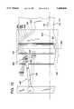
- FIG. 8is a cut-away top plan view of a machine for applying leg elastic to garment material according to an alternate embodiment of the present invention, showing a portion of the machine on one side of the longitudinal center line of the machine.
- FIG. 9is an enlarged top view of the feeder head of the embodiment shown in FIG. 8.
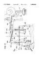
- FIG. 10is a cut-away top plan view of a machine for applying leg elastic to garment material according to yet another alternate embodiment of the present invention, showing a portion of the machine on one side of the longitudinal center line of the machine.
- FIG. 11is an enlarged elevational view of the feeder head and leading positioning fingers of FIG. 10.
- FIG. 12is an enlarged view taken along line 12--12 in FIG. 10.
- FIG. 13is a top plan view of the elastic gripper and cam shown in FIG. 12.
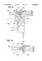
- FIG. 14is a cut-away top plan view of a machine for applying leg elastic to garment material according to another alternate embodiment of the present invention, showing a portion of the machine on one side of the longitudinal center line of the machine.
- FIG. 15is a cut-away top plan view of a machine for applying leg elastic to garment material according to an additional alternate embodiment of the present invention, showing a portion of the machine on one side of the longitudinal center line of the machine.
- FIG. 16is an enlarged top view of the feeder head of the embodiment shown in FIG. 15.
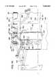
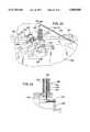
- FIG. 17is a partially cut-away top plan view of a machine for applying leg elastic to garment material according to another alternate embodiment of the present invention.
- FIG. 18is a view taken along line 18--18 in FIG. 17.
- FIG. 19is an enlarged perspective view of the top of the feeder head of the embodiment shown in FIG. 17.
- FIG. 20is an enlarged view taken along line 20--20 in FIG. 18.
- FIG. 21is an enlarged perspective view showing the bottom of the feeder head of the embodiment shown in FIG. 17.
- FIG. 22is an enlarged bottom view of the feeder head of the embodiment shown in FIG. 17.
- FIG. 23is an enlarged perspective view showing one gripper of FIG. 17.
- FIG. 24is an enlarged view of a portion of the gripper of FIG. 17, showing a cam extending a gripper spring.
- apparatus generally indicated at 10is constructed according to an embodiment of the invention.
- the apparatus illustratedis specifically adapted to produce disposable diapers or training pants, but it should be understood that it is not limited to such products.
- disposable diapers and training pantsgenerally include an outer, or backing, sheet of a liquid impervious material, onto which an absorbent pad is placed.
- a liquid pervious liner, or inner, sheetis placed thereon to encase the absorbent pad therebetween.
- an elongate sheet, or web, of backing material 14 having a selected widthis moved in one direction along a flow path 16 which extends in the machine direction.
- an elongate absorbent pad 15is placed on backing material 14, and an elongate sheet of inner liner material 17 is laid thereover.
- the liquid impervious back sheet 14may be of a thin thermoplastic material, such as a pigmented polyethylene film having a thickness in the range of 0.02-0.04 mm.
- the liquid pervious liner sheet 17may be a carded polyester fiber with a latex binder or a spun-bonded polypropylene having continuous fibers and thermally bonded by patterned calendar rolls.
- the liner sheetmay be impregnated with a surfactant to render it hydrophilic.
- the absorbent pad 15may be of wood fibers or other fibers, such as chemical wood pulp, or any other suitable moisture absorbing material such as commercially available fluff pulp or a fluffed bleached craft soft wood pump.
- a first and second set 20, 22 of elongate elastic elementseach set herein shown as including individual elastic bands 20a, 20b, 20c, and 22a, 22b, 22c, extending generally longitudinally along the flow path 16 and are adhered to the backing material 14.
- the first and second sets of bands 20, 22are arranged in a symmetric, curved contour, or pattern 21 that generally resembles a repeating hour-glass pattern, with inboard regions 25, diagonal regions 26, and outboard regions 27.
- a contoured dashed line 19 positioned along the sets of bands 20, 22indicate leg contour cut-out lines at which leg openings will be severed from the garment in the manufacturing process.
- the sets of bands 20, 22will elasticize the leg opening regions of the garments produced.
- a circular conveyer drum 28is supported on and driven about a central axle 29.
- the direction of rotationis indicated generally by arrow 29a.
- the peripheral face 30 of the drumsupports backing material 14 as it travels from the bottom side of the drum to the top side of the drum in FIG. 1.
- the drumis wider than the usual width of material to be carried thereon so that it can accommodate sheet material of different widths.
- An adhesive applicator for applying adhesive to the side of the backing material sheet 14 that receives the elasticis generally indicated at 31.
- the adhesive applicator 31preferably sprays adhesive onto the backing material upstream of the conveyor drum 28 to prevent accumulation of any possible overspray on the conveyor drum 28.
- the adhesivemay be applied over the entire outward width of the backing material sheet 14 to provide adhesion for the sets of bands 20, 22 and pads 15.
- a nip roller 32is mounted above the conveyor drum 28 for powered rotation about an axle 32a substantially parallel to drum axle 29.
- the nip rollercounter-rotates relative to the conveyor drum in the direction indicated by arrow 33 and presses against drum 28 at a nip 34.
- the roller 32carries liner material 17 adjacent and overlying backing material 14.
- the sets of bands 20, 22are pressed tightly between the drum 28 and the nip roller 32 at nip 34. This, as will be discussed later, serves to press the backing and liner materials 14, 17 tightly together over the sets of bands 20, 22.
- a pad conveyor 36is operable to carry longitudinally spaced pads 15 and insert them at the nip 34 into the space between backing sheet 14 and liner sheet 17, such that a pad will be carried by the backing and liner sheets through the nip between drum and roller 28, 32 and be captured between the two sheets.
- the combined backing and liner sheet with an absorbent pad encased therebetweenare carried downstream, to the right in FIGS. 1 and 2, and are supported on subsequent rollers 38a, 38b (FIG. 2) and other conveyor mechanism in the system as they are moved therealong.
- an elastic storage containeris generally indicated at 39.
- An elongate strip of elastic material 39bis drawn from container 39 and carried in the direction of arrow 40.
- the elastic strip materialalready has been scored during its manufacture such that it is easily split into two sets 20, 22 of three elastic bands each 20a, 20b, 20c, and 22a, 22b, 22c.
- the elasticused is 0.015 inch by 0.027 inch, three-end natural rubber obtained from Fulflex.
- the elasticmay be any form of elasticized material which may be found to be desirable for producing the product at hand. Examples of other materials which might be used are polyurethane, ribbon elastic, lycra strands, or others used in the industry.
- a splitter device which produces this function and also provides initial tensioning of the strandsis indicated generally at 41.
- This splitter deviceincludes a first pair of powered counter-rotating rollers 42a between which the elastic strip 20 is moved.
- a second set of powered counter-rotating rollers 42bare positioned downstream from rollers 42a with the elastic bands moving between the rollers 42b.
- Rollers 42bare driven at a speed slightly higher than rollers 42a, such that the elastic band are stretched in tension.
- a plurality of spaced pins 43are disposed between rollers 42a, 42b with the elastic bands being routed about the pins to separate the elastic strip 20 into six individual bands.
- an elastic feederis positioned above the conveyor drum 28 and generally indicated at 44.
- An elongate support member 48extends from a frame 46 laterally across a machine centerline 51 that extends along the center of the drum face 30 at the center of flow path 16.
- Elongate first and second swing arms 50, 52are pivotally mounted to the support member 48 at proximal swing arm ends 50a, 52a.
- the swing arms 50, 52are mounted symmetrically on either side of the machine centerline 51.
- the swing arms 50, 52extend generally in the flow path direction and support elastic feeder heads 53, 54 at the distal swing arm ends 50b, 52b.
- Arms 50, 52are mounted to swing in a reciprocating, simultaneous and symmetric fashion across the flow path 16. Accordingly, the feeder heads 53, 54 are swept in reciprocating, simultaneous and symmetric arcuate, mirror-image sweep paths 55, 56 that extend laterally across the flow path 16. Applying the sets of elastic bands 20, 22 from the reciprocating feeder heads directly to the moving sheet of backing material 14 produces the symmetric curved elastic "hour glass" contour 21.
- the sets of bands 20, 22, shown in FIG. 1are covered with liner material 17, they are shown in solid lines for clarity.
- the relatively small diameter of the nip roller 32permits the feeder heads 53, 54 to be positioned close to the nip 34 to promote the precise application of the elastic bands.
- the shape of the elastic contour 21is related to the ratio of the rate of lateral motion of the feeder head across the flow path 16 (feeder rate) and the rate of motion of the conveyor drum face 30 in the flow path direction 16 (conveyor rate).
- the elasticis applied at a maximum angle relative to the flow path 16 when the feeder rate is at its maximum speed. Accordingly, the maximum feeder rate corresponds to the contour diagonal portion 26.
- the elasticis applied parallel with the flow path when the feeder rate is zero, meaning the feeder head 53 is stationary.
- Arms 50, 52are swung by a cam mechanism 57.
- the mechanismincludes a cam mounting plate 57a that is mounted on the frame 46 and supports a horizontally rotating cam 58.
- the cam 58actuates a rocker plate 59, which has a top corner 59a and opposing base corners 59b, 59c that generally describe the corners of a triangle.
- the plate 59rocks about a vertical rocker post 60 received through the middle of the triangle base region.
- a roller at the plate top corner 59ais engaged by the cam 58 to rock the plate 59.
- a resilient biasing member 61extending from the frame 46 engages the top corner 59a of the plate 59 to urge the roller into snug engagement with the cam 58. The snug engagement yields a smooth rocking action for the plate 59.
- the shape of the curved elastic contour 21is varied by varying the shape of the cam 58.
- the camis shaped in a 6th order polynomial curve to obtain the complex curved contour 21 shown in FIG. 1.
- the preferred elastic contour 21yields garments with leg elastic having varying selected curvature from front to rear about the garment leg openings.
- any of a variety of elastic curves that are effective in retaining moisturemay be produced through application of the cam mechanism. If a simple smooth curved contour is desired, an eccentrically mounted circular cam could be used.
- the cam mechanism 57may be driven by a belt 62 and pulley 63a, 63b mechanism.
- a cam pulley 63ais mounted on cam shaft 63c beneath the cam 58 in planar registration with a drive pulley 63b that is mounted on a powered drive shaft 65.
- the belt 62is trained about the pulleys 63a, 63b to drive the cam 58.
- First and second connecting rods 64, 66extend from proximal pivot attachments 64a, 66a at the opposing base corners 59b, 59c of the rocker plate 59, to distal pivot attachments 64b, 66b on intermediate portions of the swing arms 50, 52.
- the first connecting rod 64is shorter than the second connecting rod 66.
- the rocker post 60is positioned slightly downstream along the flow path 16 relative to the distal pivot attachments 64b, 66b, such that the connecting rods 64, 66 swing their respective swing arms 50, 52 through substantially identical swing angles. In this way, the attached feeder heads 53, 54 move through substantially identical arcuate paths 55, 56.
- the feeder head 53 of FIGS. 1 and 2is shown enlarged in FIGS. 3-5.
- the feeder head 53is adapted to apply three elastic bands 20a, 20b, 20c with a constant, equi-distant spacing between adjacent elastic bands, throughout the curved elastic contour 21. Further details and alternative embodiments of the feeder will be discussed hereafter.
- the feeder heads 53, 54extend downward from the distal ends of swing arms 50, 52.
- the feeder headsare cylindrical and oriented generally perpendicular to the flow path 16.
- the feeder heads 53, 54are fixed relative to the swing arms 50, 52.
- a diagonal slot 82 in the swing arm 50guides the elastic bands 20a, 20b, 28c to the feeder head 53.
- the slot 82is cut into the inboard portion of the swing arm 50 adjacent the feeder head 53 and extends rearward (opposite the flow path 16) to the longitudinal center of the swing arm 50.
- the three bands 20a, 20b, 20care guided from above through the diagonal slot 82 to the feeder head.
- a central band 20bis guided through a central slot 84 in the feeder head 53.
- the central slot 84extends diagonally from the top edge of the feeder head to the center of the bottom surface 85 of the feeder head 53.
- the top of the central slot 84is positioned adjacent the terminus of the diagonal slot 82 at the swing arm centerline.
- the central band 20bextends through the central slot 84 for constant application from the center of the feeder head bottom.
- the outermost elastic bands 20a, 20care guided through a pair of opposing, L-shaped guides 86a, 86b around the circular periphery of the feeder head 53.
- the L-shaped guides 86a, 86bextend horizontally from a rear portion of the cylindrical feeder head 53.
- Each L-shaped guide 86a, 86bhas a distal leg directed inwardly toward the opposite L-shaped guide.
- the guides 86a, 86bare closely spaced such that the outer elastic bands 20a, 20c are constantly applied tangentially from the cylindrical feeder head 53.
- the feeder headhas a diameter equal to the selected spacing between the outermost individual elastic bands 20a, 20c.
- FIG. 1shows an overview of such an elastic contour 21.
- the cylindrical feeder head 53may also be utilized to apply a single elastic band through the central slot, or about the head periphery.
- the feeder head 53may apply a pair of elastic bands with constant equidistant spacing.
- one of the bandsmay be guided through the central slot 84 and one about the head periphery, or both bands may be guided about the head periphery.
- elastic grippers 88are fixed at intervals along the opposing outboard edges of the conveyer drum face 32, as shown in FIG. 1.
- the width of the material sheets 14, 17is selected such that the material is positioned between the grippers 88.
- the nip roller 32is longitudinally somewhat shorter than the drum conveyer 28, so that the nip roller 32 rotates between the opposing grippers 88.
- the grippersare adapted to hold the elastic bands 20a, 20b, 20c of the outboard contour region 27 in tension outboard of the material. As shown in FIG. 1, the feeder head 53 sweeps laterally to an outboard position adjacent the grippers 88 such that the elastic bands 20 are applied outboard of the material 14, 17, nip roller 32, and gripper 88. The elastic bands 20 applied outboard of the grippers 88 and nip roller 32 are not pinched at the nip 34 and thus contract inward into engagement with the gripper 88.
- the gripper 88is elongate and has a longitudinal slot 90, or holding bay, in the outboard face 91 that receives the contracting elastic bands 20.
- a locking pin 92 having a notch 96extends through a bore 93 in the gripper and is actuable to grip the elastic bands 20 within the slot 90.
- the pin 92is mounted upon a coil spring 94 to normally bias the pin upwardly to a lock position. In the lock position, the pin notch 96 moves into an upper portion of the bore 93, and the top 97 of the pin 92 protrudes from the top of the gripper 88.
- a stationary cam 98depresses the locking pin top 97 such that the pin notch 96 moves downwardly into alignment with the slot 90.
- the cam 98is fixed adjacent the nip 34 to depress the locking pin 92 as the elastic is applied outboard of the gripper 88.
- the cam 98releases the pin 92 downstream of the nip 34 to return the pin 92 to the lock position wherein the elastic is gripped between the bottom of the notch 96 and the top of the longitudinal slot 90.
- the elastic bands 20a, 20b, 20c gripped by the grippers 88extend outwardly in tension from opposing edges of the overlaid sheets 14, 17 of garment material.
- a cutting blade 100 mounted downstream of the nip 34severs the gripped outboard elastic bands adjacent the edges of the overlaid sheets 14, 17.
- the grippers 88release the severed lengths of elastic adjacent the bottom side of the drum 28.
- stationary release cams 102are positioned on either side of the bottom of the conveyor drum 28 to depress the locking pins 92 and permit the severed lengths of elastic to fall out of the grippers 88.
- a garmentis formed with elastic bands 20a, 20b, 20c extending about the leg openings, but not fully up the sides of the garment.
- FIGS. 8shows a machine embodiment with a pivotal feeder head 53c that permits selected spacing between a plurality of individual elastic bands.
- the feeder headis adapted to apply four bands 20a, 20b, 20c, 20d.
- the feeder head 53cis pivotally attached to the distal end of the swing arm 50c.
- the feeder head 53cis block-shaped, with four elastic outlet apertures 104 for applying the four elastic bands.
- the apertures 104extend vertically through the head in a fixed spatial relation to one another, and are aligned in an aperture line 107 extending across the bottom surface of the head 53c.
- the elastic bands 20a-20dare guided through the top of the apertures 104 and exit the bottom of the apertures along the aperture line 107.
- the feeder head 53cpivots about a vertical pivot pin 108 at the distal end of the swing arm 50c.
- the distal end of the swing arm 50chas an enlarged orientation surface 110 extending perpendicular to the length of the swing arm 50c.
- a biasing meanssuch as a torsion spring 112, biases the feeder head 53c against the orientation surface 110 to normally orient the aperture line 107 substantially perpendicular to the length of the swing arm 50c.
- the torsion spring 112has a coiled portion 114 that is centered about the pivot pin 108.
- First and second lever arms 116, 118extend from opposite ends of the coil 114.
- the first lever arm 116is held static by an anchor pin 120 extending from the top of the swing arm 50c.
- the second lever arm 118engages the feeder head 53c to pivotally bias it against the orientation surface 110.
- a cam 105is positioned adjacent the inboard portion of the arcuate path 55c (FIG. 8) traced out by feeder head 53c to selectively pivot the feeder head.
- the cam 105has a curved cam face 122 that is engaged by a roller 124 on the inboard downstream corner of the feeder head 53c.
- the elastic bands 20a-20dextend from the aperture line 107 beneath the cam 105 for application adjacent the nip 34c.
- the diagonal elastic portion 26cis applied when the swing arm 50c is substantially parallel to the flow path 16c.
- the aperture line 107is substantially perpendicular to the flow path 16c. Since the bands 20a, 20b, 20c, 20d extend diagonally from the aperture line 107, the spacing between the elastic bands of the diagonal portion 26c is narrower than the spacing between the apertures 104. The spacing becomes narrower as the angle (designated by arrow 125) between the contour diagonal portion 26c and the flow axis 16c increases.
- the spacing between the individual elastic bands 20a-20d(spacing between outlet apertures 104) ⁇ cos (angle 125).
- the feeder ratemomentarily becomes zero at each end of the arcuate path 55c.
- the swing arm 50cis slightly angled from the flow path 16c by one-half of the included angle (designated by arrow 126) of the arcuate path 55c.
- the aperture line 107is angled from the perpendicular to the flow path 16c by the same amount.
- the elasticis applied parallel to the flow path 16c so that the spacing between the individual elastic bands 20a-20d is slightly less than the spacing between the apertures 104 (but greater than the spacing between the bands of the diagonal portion 26c).
- the spacing between the elastic bands of the outboard region 27c(spacing between the outlet apertures 104) ⁇ cos (angle 126).
- the cam 105pivots the feeder head 53c to avoid the relatively wide spacing of the outboard region 27c.
- the cam 105pivots the feeder head 53c so that the elastic bands exit from the outlet line 107 at an angle generally equal to the angle of the diagonal region 26c relative to the flow axis 16c. Therefore, the spacing between the elastic bands 20 of the inboard region 25c and diagonal region 26c is substantially equal.
- the cam 105gradually pivots the feeder head 53c as the feeder rate decreases near the inboard end of the arcuate path 55c.
- the entire elastic contour 21cis encased between the overlaid backing sheet 14c and liner sheets 17c.
- the drum 28c and nip roller 32care as least as long as the width of the material 14, 17. No grippers are required.
- a cutting blade 130is fixedly positioned for this purpose downstream of the nip roller 32c.
- FIGS. 10-12show another alternative embodiment with a cam 105d and pivotable feeder head 53d similar to those shown in FIGS. 8 and 9.
- the feeder head 53dis pivoted by a cam 105d at the inboard end of the arcuate path 55d to maintain constant spacing between elastic bands at the inboard 25d and diagonal 26d contour portions.
- the outboard contour regions 27dextend laterally outboard of the edge of the material sheets 14d, 17d.
- the outboard extending elastic regions 27dare gripped in tension by elastic grippers 88d.
- the grippers 88dare mounted at intervals on a second conveyor 132 to receive the bands of each outboard elastic region 27d.
- the second conveyor 132runs parallel to one side of the flow path 16d at a speed equal to the conveyor speed.
- the conveyor 132may run about a pair of powered spaced rollers 135.
- the feeder head 53dmoves adjacent the gripper 88d when at the outboard end of the arcuate path 55d. When so positioned, the feeder head 53d applies the bands 20a, 20b, 20c, 20d to the gripper 88d.
- the gripperfirst receives the bands between a plurality of vertical positioning fingers 134a that extend in a row transversely across the second conveyor 132.
- the bottom surface of the feeder head 53dhas a plurality of protruding feeder fingers 136 through which the outlet apertures 104d extend.
- the moving positioning fingers 134ainterdigitate with the feeder fingers 136 such that the elastic bands 20a, 20b, 20c, 20d are fed between the positioning fingers 134a.
- the tension in the elastic bands 20causes the bands to move into position against the positioning fingers 134a.
- the fingershave substantially inverted conical shapes that securely urge the elastic bands 20a, 20b, 20c, 20d downwardly toward the second conveyor 132.
- the gripper 88dincludes a pair of gripper plates 138 that sandwich a slidable spring-biased locking plate 140 therebetween.
- a pin 148 fixed in both gripper plates 138extends through an elongate slot 150 in the locking plate to interconnect the plates 138, 140.
- the gripper plates and locking platerespectively, have a plurality of upwardly oriented gripper fingers 142, and locking fingers 144.
- the locking plate 140is ordinarily biased by the spring 139 to offset the gripper and locking fingers 142, 144 in a lock position (FIG. 12).
- the locking plate 140has a roller 145 that is engagable by a stationary cam 146 to slide the locking plate to an open position. As shown in FIG. 13, the gripper and locking fingers 142, 144 are aligned to interdigitate with the feeder fingers 136 in the open position. In this fashion, the feed head positions the bands 20a, 20b, 20c, 20d between the open fingers 142, 144 of the gripper 88d.
- the cam 146releases the locking plate to return the gripper 88d to the lock position wherein the bands are gripped between the offset fingers 142, 144 (FIG. 12).
- a trailing row of positioning fingers 134bsimilar to fingers 134a, next interdigitate with the feeder fingers 136 to position the trailing bands of the outboard contour region 27d.
- the feeder head 53dthen swings inboard to apply the diagonal elastic region 26d.
- the leading and trailing fingers 134a, 134bposition the elastic bands such that the diagonal contour region 26d relative to the flow axis 16d is at a selected angle.
- the outboard elastic region 27d gripped by the gripper 88dis severed at the edge of the assembled material sheets 14d, 17d.
- a stationary cutting blade 130dis positioned downstream from the roller 32d to first sever the leading bands of the outboard contour 27d.
- the trailing bands of the outboard contour region 27dremain held in tension by the gripper 88d until severed by cutter 130d.
- the embodiment shown in FIG. 14has a pair of cams 105e, 152e positioned at both ends of the arcuate feeder head path 55e to provide constant spacing between the individual elastic bands 20 throughout the inboard, diagonal, and outboard elastic regions 25e, 26e, 27e.
- Cam 105eis positioned adjacent the inboard end of arcuate path 55e to pivot the feeder head 53e as described in the first alternate embodiment (FIGS. 8 and 9). As shown in FIG. 14, opposing cam 152e is positioned adjacent the outboard end of arcuate path 55e to similarly pivot the feeder head 53e as the bands 20a, 20b, 20c, 20d of the outboard elastic region 27e are applied.
- the feeder head 53ehas rollers 124e at both ends for engaging the opposing cams 105e, 152e.
- Feeder head 53eis somewhat similar to feeder head 53c of FIGS. 8 and 9. However, feeder head 53e must be able to pivot on both sides of the distal end of swing arm 50e. Thus, as shown in FIG. 14, the swing arm 50e does not have an enlarged distal orientation surface.
- Feeder head 53emay be provided with resilient biasing means to normally urge the feeder head into a perpendicular position at the distal end of swing arm 50e.
- the opposing cams 105e, 152emay be extended to abut and form a unitary cam surface. Such a unitary cam may continuously position the feeder head if both rollers 124e continuously engage unitary cam surface, in which case no biasing means is needed.
- the material sheets 14e, 17ehave a selected width to encase the entire elastic contour 21e. Thus, there is no need for scrapping a margin portion of the material. In this way, a garment is produced with an elastic contour 21e having constant spacing between the bands 20a-20d, and extending completely up the sides of the garment.
- FIGS. 15 and 16has a feeder head 53f that is freely pivotable about a vertical pivot shaft 108f at the distal end of the swing arm 50f.
- the feeder head 53fis freely pivoted by the tension of the elastic bands 20a, 20b, 20c, 20d held at the nip 34f, as the feeder head 53f moves laterally across the flow path (FIG. 15).
- the pivotingis such that the elastic bands 20 generally always extend perpendicular to the aperture line 107f.
- the applied elastic bands 20a, 20b, 20c, 20dalways have a spacing equal to the spacing between the outlet apertures 104f.
- band spacingremains constant throughout the inboard 25f, diagonal 26f, and outboard contour regions 27f.
- FIG. 15shows materials 14f, 17f having a selected width to completely encase all regions 25f, 26f, 27f of the elastic contour. While no trimming of an material edge margin is shown, such trimming may be undertaken if desired.
- FIGS. 17-24shows another embodiment of a leg elastic applicator.
- swing arms 50g, 52gare pivotally reciprocated across the flow path 16g by first and second connecting rods 64g, 66g.
- First rod 64ginterconnects the rocker plate 59g and the swing arm 50g
- second rod 66ginterconnects the pair of swing arms 50g, 52g.
- Such a connecting configurationpermits a relatively short second rod 66g to help minimize connecting arm inertia during machine operation.
- Arm 50gpivots about a pivot shaft 250c extending from a support member 48g.
- the upstream end of arm 50gis pivotally attached to connecting rod 64g at a pivot shaft 250a, spaced a selected distance from pivot shaft 250c.
- Connecting rod 66gis pivotally attached to arm 50g at a pivot shaft 250d, which is spaced an equal selected distance downstream from the shaft 250c.
- Rod 66gextends to attach at a pivot shaft 252a on the upstream end of swing arm 52g.
- Swing arm 52gpivots on the support member 48g at pivot shaft 252c, which is spaced the selected distance downstream from shaft 252a.
- the equal selected spacings between pivot shaftspermit the swing arms 50g, 52g to pivot symmetrically through identical swing angles.
- Swing arms 50g, 52gare telescopic. As best seen in FIG. 18, buttons 252e supported by spring 252f protrude from the top and bottom of swing arm 52g to lock the arm in an extended position. The buttons 252e may be manually depressed into the arm so that a distal portion 252b of the arm 52g may be telescopically retracted into the arm.
- this embodimenthas a feeder head 53g that applies three elastic bands 20a, 20b, 20c from three platforms 254a, 254b, 254c having different elevational levels.
- the elastic bands 20a, 20b, 20care guided to the feeder head 53g around a guide bar 256 extending laterally across the top of the feeder head 53g.
- the elastic bands 20a, 20b 20care guided through band grooves 258a, 258b, 258c defined vertically through the back of feeder head 53g.
- the outside elastic bands 20a and 20care guided around vertical outer side guide surfaces 260a and 260c.
- the guide surfaces 260a, 260chave arcuate contours that together define a circular profile (see FIG. 22). The guide surfaces thus permit a selected constant spacing between the elastic bands 20a, 20b, 20c in a way similar to the cylindrical feeder head 53b shown in FIGS. 3-5.
- the feeder head 53gapplies the elastic bands from the three offset platforms to cooperate with an alternative elastic gripper 288.
- outboard extending elastic regions 27gare gripped in tension by grippers 288, which are mounted at intervals along the opposing outboard edges of the conveyor drum face 32g.
- the gripper 288engages the elastic bands 20a, 20b, 20c when the feeder head 53g is moved adjacent the gripper at the outboard end of arcuate path 55g.
- the gripper 288comprises an elongate coil spring 290 that receives the bands 20a, 20b, 20c between its contracted coils.
- the springis radially mounted on the drum and is extendable by an L-shaped extension rod 294.
- the vertical portion of the rod 294extends axially through the coil spring and is fixed to the spring top by a fitment 297. The spring coils abut tightly against one another when the spring is not extended.
- the lateral portion 295 of the L-shaped rod 294is positioned to engage the ramped upper surface of a fixed cam 292, which acts to extend spring 290, thereby producing openings between adjacent spring coils that act as holding bays to receive the elastic bands 20a, 20b, 20c at different levels.
- the cam 292is fixedly positioned adjacent the nip 34g to extend the spring before the feeder head 53g moves outside the gripper. As the gripper 288 moves by the feeder head 53g, the cam releases the rod 294 to permit retraction of the coil spring, thereby gripping the bands between the coils.
- a trailing row of positioning fingers 298a, 298b, 298care fixed along the length of the edge of the conveyor face 32g to receive the elastic bands 20a, 20b, 20c.
- the fingersmay be screws with heads to retain the individual elastic bands.
- the leading screw 298ahas a relatively high head elevation to receive the highest elevation elastic band 20a
- the intermediate screw 298bhas an intermediate head level to receive intermediate band 20b
- the trailing screw 298chas a relatively low head level to receive lowest band 20c.
- the positioning of the screws 298a, 298b, 298cguides the bands 20a, 20b, 20c through the trailing diagonal contour portion 26g with the selected spacing between the bands.
- a stationary cutting blade 300 positioned downstream of the nip 34gsevers the leading bands held by the coil spring 290.
- the trailing elastic bandsare held in tension by the retracted coil spring 290 until severed by blade 300.
- Another cam(not shown) is positioned adjacent a lower portion of the drum to extend the coil spring 290 so that the severed portions of the elastic bands fall from the spring 290 as scrap.
- feeder heads 53, 53c, 53d, 53e, 53f, 53g, grippers 88, 88d, 288, and edge margin portion trimmingare described. It is to be understood other combinations of particular feeder heads, grippers, and margin trimming treatments will work equally as well.
- the grippers 88, 88dare not necessary for the use of any particular feeder head. If feeder head 53 is used without the gripper 88 and with material and a nip roller of sufficient width, a garment may be produced encasing the entire curved elastic contour and having constant spacing between the elastic bands throughout the entire curved contour. If no cutter is used, the elastic contour will extend fully up the sides of the finished garment. If a garment edge margin is trimmed away, the elastic contour will only extend along the leg openings in the finished garment.
- garment backing material 14is moved in one direction along the flow path 16, which includes movement from bottom to top about drum 28. Prior to reaching the drum, adhesive is applied to the side of the backing material facing outward from the drum 28.
- a source 39 of a plurality of elongate elastic bands 39bis provided that are guided onto the material in first and second sets, each set including a plurality, of bands 20, 22.
- the first and second band setsare guided from first and second positions moving symmetrically and laterally across the backing material relative to the flow path direction such that the first and second sets of elastic bands are deposited on the material in a pair of symmetric curved contours 21.
- the elastic bandsare deposited on the backing material adjacent the nip 34 of the drum 24 and a counter-rotating nip roller 32.
- the bandsmay be held in tension as they are so deposited.
- Liner material 17may be laid over the backing material 14 and the sets of bands 20, 22 to encase the bands at the nip.
- the encasement stepincludes tightly pinching the sets of bands between the nip roller and drum.
- a selected spacingmay be maintained between individual elastic bands in the first and second sets of bands 20, 22 throughout the curved contour.
- the individual elastic bands of the first and second setsmay be guided onto the material from guide points, such as those established by cylindrical feeder head 53a.
- the guide pointsmay also be outlet apertures 104 arranged along line 107 in the feeder heads 53c, 53d, 53e, 53f. The line is pivoted relative to the one direction during the lateral movement of the first and second positions.
- the linemay be freely pivoted by the tension in the elastic bands (FIGS. 15 and 16).
- the linemay be normally biased toward a particular position, and a cam used to selectively pivot the line away from the particular position (FIGS. 8, 9, 10, and 14).
- a selected spacing between the outermost bands 20a, 20c in a setmay be accomplished by guiding those bands about the periphery of a feeder head 53a with a selected side-to-side dimension.
- Three elastic bands 20a, 20b, 20cmay be deposited with constant equidistant spacing between each band where the intermediate band 20b is guided through the center of the feeder head 53a.
- the methodmay also comprise providing material with a defined width such that the curved contour formed by the first and second sets of elastic bands extends at spaced intervals laterally outwardly beyond the edges of the material.
- the elastic bands so positioned outboard of the materialmay be gripped and held in tension prior to being severed adjacent the edge of the material.
- the methodmay include the step of trimming a side margin portion of the overlaid backing and liner material.
Landscapes
- Health & Medical Sciences (AREA)
- Engineering & Computer Science (AREA)
- Vascular Medicine (AREA)
- Epidemiology (AREA)
- Biomedical Technology (AREA)
- Heart & Thoracic Surgery (AREA)
- Manufacturing & Machinery (AREA)
- Life Sciences & Earth Sciences (AREA)
- Animal Behavior & Ethology (AREA)
- General Health & Medical Sciences (AREA)
- Public Health (AREA)
- Veterinary Medicine (AREA)
- Absorbent Articles And Supports Therefor (AREA)
Abstract
Description
Claims (7)
Priority Applications (1)
| Application Number | Priority Date | Filing Date | Title |
|---|---|---|---|
| US08/617,411US5660664A (en) | 1994-04-26 | 1996-03-18 | Method of applying leg elastic |
Applications Claiming Priority (2)
| Application Number | Priority Date | Filing Date | Title |
|---|---|---|---|
| US08/233,247US5500075A (en) | 1994-04-26 | 1994-04-26 | Leg elastic applicator which maintains the spacing between the elastics substantially constant |
| US08/617,411US5660664A (en) | 1994-04-26 | 1996-03-18 | Method of applying leg elastic |
Related Parent Applications (1)
| Application Number | Title | Priority Date | Filing Date |
|---|---|---|---|
| US08/233,247DivisionUS5500075A (en) | 1994-04-26 | 1994-04-26 | Leg elastic applicator which maintains the spacing between the elastics substantially constant |
Publications (1)
| Publication Number | Publication Date |
|---|---|
| US5660664Atrue US5660664A (en) | 1997-08-26 |
Family
ID=22876497
Family Applications (2)
| Application Number | Title | Priority Date | Filing Date |
|---|---|---|---|
| US08/233,247Expired - LifetimeUS5500075A (en) | 1994-04-26 | 1994-04-26 | Leg elastic applicator which maintains the spacing between the elastics substantially constant |
| US08/617,411Expired - Fee RelatedUS5660664A (en) | 1994-04-26 | 1996-03-18 | Method of applying leg elastic |
Family Applications Before (1)
| Application Number | Title | Priority Date | Filing Date |
|---|---|---|---|
| US08/233,247Expired - LifetimeUS5500075A (en) | 1994-04-26 | 1994-04-26 | Leg elastic applicator which maintains the spacing between the elastics substantially constant |
Country Status (2)
| Country | Link |
|---|---|
| US (2) | US5500075A (en) |
| WO (1) | WO1995028902A1 (en) |
Cited By (62)
| Publication number | Priority date | Publication date | Assignee | Title |
|---|---|---|---|---|
| KR20010000150A (en)* | 2000-07-01 | 2001-01-05 | 정해항 | Manufacturing Equipment of Diaper Use for Adult and Panty Type Diaper |
| US6284081B1 (en) | 1999-12-23 | 2001-09-04 | Kimberly-Clark Worldwide, Inc. | Methods and apparatus for applying an elastic material in a curvilinear pattern on a continuously moving substrate |
| US6287409B1 (en) | 1999-12-23 | 2001-09-11 | Kimberely-Clark Worldwide, Inc. | Methods and apparatus for applying an elastic material in a curvilinear pattern on a continuously moving substrate |
| US6387471B1 (en) | 1999-03-31 | 2002-05-14 | Kimberly-Clark Worldwide, Inc. | Creep resistant composite elastic material with improved aesthetics, dimensional stability and inherent latency and method of producing same |
| WO2002013746A3 (en)* | 2000-08-15 | 2002-06-13 | Kimberly Clark Co | Method of optimizing spacing between elastic members in applying leg elastics |
| US20020134491A1 (en)* | 2000-07-24 | 2002-09-26 | Illinois Tool Works Inc. | Variable spacing strand coating method |
| US6547915B2 (en) | 1999-04-15 | 2003-04-15 | Kimberly-Clark Worldwide, Inc. | Creep resistant composite elastic material with improved aesthetics, dimensional stability and inherent latency and method of producing same |
| US6569275B1 (en)* | 2000-08-15 | 2003-05-27 | Kimberly-Clark Worldwide, Inc. | Method of optimizing tension in applying leg elastics |
| US6569139B1 (en) | 2000-06-22 | 2003-05-27 | Kimberly-Clark Worldwide, Inc. | Disposable absorbent underpants for containing body fluid |
| US6572596B2 (en) | 2001-05-15 | 2003-06-03 | Paragon Trade Brands, Inc. | Convertible diaper |
| US20030116257A1 (en)* | 2001-12-20 | 2003-06-26 | Kimberly-Clark Worldwide, Inc. | Apparatus and method for applying an elongate member to a substrate |
| US20030120246A1 (en)* | 2001-12-20 | 2003-06-26 | Kimberly-Clark Worldwide, Inc. | Elastic composites for garments |
| US6589149B1 (en)* | 2000-08-15 | 2003-07-08 | Kimberly-Clark Worldwide, Inc. | Method and apparatus for applying a curved component to a moving web |
| US6610161B2 (en) | 2001-12-17 | 2003-08-26 | Paragon Trade Brands, Inc. | Elastic strand coating process |
| US20030236512A1 (en)* | 2002-06-19 | 2003-12-25 | Baker Andrew A. | Absorbent core with folding zones for absorbency distribution |
| US20040006323A1 (en)* | 2002-07-02 | 2004-01-08 | Hall Gregory K. | Garments using elastic strands to enhance performance of elastic barrier adhessive |
| US20040158217A1 (en)* | 2001-11-06 | 2004-08-12 | Wu Lanying Z. | Cloth-like laminate and absorbent garment |
| US6833179B2 (en) | 2000-05-15 | 2004-12-21 | Kimberly-Clark Worldwide, Inc. | Targeted elastic laminate having zones of different basis weights |
| US20050000628A1 (en)* | 2003-03-07 | 2005-01-06 | Sca Hygiene Products Ab. | Method for applying elastic members on a pant-shaped absorbent article |
| US20050013940A1 (en)* | 2003-07-18 | 2005-01-20 | Illinois Tool Works Inc. | Strand orientation alignment in strand coating systems and methods |
| US20050101929A1 (en)* | 2002-01-17 | 2005-05-12 | Andrew Waksmundzki | Absorbent core with three-dimensional sub-layer |
| US20050107759A1 (en)* | 2002-01-17 | 2005-05-19 | Andrew Waksmundzki | Absorbent article with three-dimensional extrudate forming sap containment wells |
| US6902796B2 (en) | 2001-12-28 | 2005-06-07 | Kimberly-Clark Worldwide, Inc. | Elastic strand bonded laminate |
| US6916750B2 (en) | 2003-03-24 | 2005-07-12 | Kimberly-Clark Worldwide, Inc. | High performance elastic laminates made from high molecular weight styrenic tetrablock copolymer |
| US6939334B2 (en) | 2001-12-19 | 2005-09-06 | Kimberly-Clark Worldwide, Inc. | Three dimensional profiling of an elastic hot melt pressure sensitive adhesive to provide areas of differential tension |
| US6967178B2 (en) | 2002-07-02 | 2005-11-22 | Kimberly-Clark Worldwide, Inc. | Elastic strand laminate |
| US6969441B2 (en) | 2000-05-15 | 2005-11-29 | Kimberly-Clark Worldwide, Inc. | Method and apparatus for producing laminated articles |
| US20050274318A1 (en)* | 2004-06-09 | 2005-12-15 | Illinois Tool Works Inc. | Strand guide implements or mechanisms for use in connection with material dispensing and coating nozzles |
| US6978486B2 (en) | 2002-07-02 | 2005-12-27 | Kimberly-Clark Worldwide, Inc. | Garment including an elastomeric composite laminate |
| US20060069375A1 (en)* | 2004-09-29 | 2006-03-30 | Andrew Waksmundzki | Absorbent article with C-folded moisture barrier and methods of manufacturing same |
| US20060069367A1 (en)* | 2004-09-29 | 2006-03-30 | Andrew Waksmundzki | Absorbent core having two or more types of superabsorbent |
| US20060151092A1 (en)* | 2005-01-07 | 2006-07-13 | Innovative Elastics Limited | Process for forming a laminate |
| US20060185135A1 (en)* | 2002-11-12 | 2006-08-24 | Hiroki Yamamoto | Process and apparatus to attach elastic members to disposable wearing article being continuously manufactured |
| US20060228969A1 (en)* | 2005-04-07 | 2006-10-12 | Erdman Edward P | Elastic laminate |
| GB2427003A (en)* | 2005-06-06 | 2006-12-13 | Steven Peace | Portable renewable energy apparatus |
| US7150731B2 (en) | 1997-11-17 | 2006-12-19 | Kimberly-Clark Worldwide, Inc. | Disposable absorbent underpants |
| US7316842B2 (en) | 2002-07-02 | 2008-01-08 | Kimberly-Clark Worldwide, Inc. | High-viscosity elastomeric adhesive composition |
| US7316840B2 (en) | 2002-07-02 | 2008-01-08 | Kimberly-Clark Worldwide, Inc. | Strand-reinforced composite material |
| US7335273B2 (en) | 2002-12-26 | 2008-02-26 | Kimberly-Clark Worldwide, Inc. | Method of making strand-reinforced elastomeric composites |
| US7344524B2 (en) | 1997-11-17 | 2008-03-18 | Kimberly-Clark Worldwide, Inc. | Disposable absorbent underpants |
| US20080105384A1 (en)* | 2006-11-06 | 2008-05-08 | The Procter & Gamble Company | Method and apparatus for nonlinear laying of material |
| US20090000545A1 (en)* | 2007-06-29 | 2009-01-01 | Illinois Tool Works Inc. | Strand positioning guide having reversely oriented V-shaped slots for use in connection with strand coating applicators |
| US7601657B2 (en) | 2003-12-31 | 2009-10-13 | Kimberly-Clark Worldwide, Inc. | Single sided stretch bonded laminates, and methods of making same |
| US7651653B2 (en) | 2004-12-22 | 2010-01-26 | Kimberly-Clark Worldwide, Inc. | Machine and cross-machine direction elastic materials and methods of making same |
| US20100078127A1 (en)* | 2008-11-11 | 2010-04-01 | Uni-Charm Corporation | Manufacturing method of absorbent article and manufacturing apparatus of absorbent article |
| US20100193138A1 (en)* | 2009-01-30 | 2010-08-05 | Joseph Allen Eckstein | System for High-Speed Continuous Application of a Strip Material to a Moving Sheet-Like Substrate Material at Laterally Shifting Locations |
| US20100193135A1 (en)* | 2009-01-30 | 2010-08-05 | Joseph Allen Eckstein | System and Method for High-Speed Continuous Application of a Strip Material to a Moving Sheet-Like Substrate Material at Laterally Shifting Locations |
| US20100193110A1 (en)* | 2009-01-30 | 2010-08-05 | Joseph Allen Eckstein | Method for High-Speed Continuous Application of a Strip Material to a Substrate Along an Application Path on the Substrate |
| US20120055613A1 (en)* | 2009-04-30 | 2012-03-08 | Sca Hygiene Products Ab | Method for providing an elasticated web |
| US8171972B2 (en) | 2009-01-30 | 2012-05-08 | The Procter & Gamble Company | Strip guide for high-speed continuous application of a strip material to a moving sheet-like substrate material at laterally shifting locations |
| US20120111485A1 (en)* | 2009-07-08 | 2012-05-10 | Uni-Charm Corporation | Method and apparatus for making disposable diaper |
| US8182457B2 (en) | 2000-05-15 | 2012-05-22 | Kimberly-Clark Worldwide, Inc. | Garment having an apparent elastic band |
| US8607959B2 (en) | 2012-04-16 | 2013-12-17 | The Procter & Gamble Company | Rotational assemblies and methods for transferring discrete articles |
| US20140041783A1 (en)* | 2011-02-23 | 2014-02-13 | Unicharm Corporation | Apparatus for manufacturing absorbent article and method for manufacturing absorbent article |
| US8720666B2 (en) | 2012-04-16 | 2014-05-13 | The Procter & Gamble Company | Apparatuses for transferring discrete articles |
| US8820513B2 (en) | 2012-04-16 | 2014-09-02 | The Procter & Gamble Company | Methods for transferring discrete articles |
| US8833542B2 (en) | 2012-04-16 | 2014-09-16 | The Procter & Gamble Company | Fluid systems and methods for transferring discrete articles |
| US9266314B2 (en) | 2012-10-23 | 2016-02-23 | The Procter & Gamble Company | Carrier members or transfer surfaces having a resilient member |
| US9463942B2 (en) | 2013-09-24 | 2016-10-11 | The Procter & Gamble Company | Apparatus for positioning an advancing web |
| US9511952B1 (en) | 2015-06-23 | 2016-12-06 | The Procter & Gamble Company | Methods for transferring discrete articles |
| US9511951B1 (en) | 2015-06-23 | 2016-12-06 | The Procter & Gamble Company | Methods for transferring discrete articles |
| US10059553B2 (en) | 2012-06-29 | 2018-08-28 | The Procter & Gamble Company | System and method for high-speed continuous application of a strip material to a moving sheet-like substrate material |
Families Citing this family (66)
| Publication number | Priority date | Publication date | Assignee | Title |
|---|---|---|---|---|
| SE513818C2 (en)* | 1994-12-21 | 2000-11-06 | Sca Hygiene Prod Ab | Flexible absorbent article comprising strips of elastic film and method of manufacturing the same |
| US20060064069A1 (en)* | 2000-04-12 | 2006-03-23 | Rajala Gregory J | Disposable undergarment and related manufacturing equipment and processes |
| US5745922A (en)* | 1995-01-31 | 1998-05-05 | Kimberly Clark Corporation | Disposable garment and related manufacturing equipment and methods |
| SE513314C2 (en) | 1998-12-29 | 2000-08-21 | Sca Hygiene Prod Ab | Method and apparatus for applying elastic to a running web of material |
| US20050106971A1 (en)* | 2000-05-15 | 2005-05-19 | Thomas Oomman P. | Elastomeric laminate with film and strands suitable for a nonwoven garment |
| US6375769B1 (en) | 2000-08-15 | 2002-04-23 | Kimberly-Clark Worldwide, Inc. | Method of applying curved leg elastics using pucks with curved surfaces |
| US6613033B1 (en) | 2000-08-15 | 2003-09-02 | Kimberly-Clark Worldwide, Inc. | Pant-like absorbent garments having curved leg cuffs |
| US6652504B1 (en) | 2000-08-15 | 2003-11-25 | Kimberly-Clark Worldwide, Inc. | Pant-like absorbent garments having curved leak guard flaps |
| US6540857B1 (en) | 2000-08-15 | 2003-04-01 | Kimberly-Clark Worldwide, Inc. | Method of applying curved leg elastics using curved pucks |
| US6635041B1 (en) | 2000-08-15 | 2003-10-21 | Kimberly-Clark Worldwide, Inc. | Absorbent garment with asymmetrical leg elastic tension |
| US6689115B1 (en) | 2000-08-15 | 2004-02-10 | Kimberly-Clark Worldwide, Inc. | Absorbent garment with asymmetrical leg elastic spacing |
| US6440246B1 (en) | 2000-08-15 | 2002-08-27 | Kimberly-Clark Worldwide, Inc. | Method of applying curved leg elastics using rotating disks |
| US20050010188A1 (en)* | 2003-07-10 | 2005-01-13 | Glaug Frank S. | Efficiently manufacturable absorbent disposable undergarment and method of manufacturing absorbent disposable article |
| US20050142339A1 (en)* | 2003-12-30 | 2005-06-30 | Price Cindy L. | Reinforced elastic laminate |
| US8417374B2 (en) | 2004-04-19 | 2013-04-09 | Curt G. Joa, Inc. | Method and apparatus for changing speed or direction of an article |
| US7638014B2 (en) | 2004-05-21 | 2009-12-29 | Curt G. Joa, Inc. | Method of producing a pants-type diaper |
| US20070048497A1 (en)* | 2005-08-31 | 2007-03-01 | Peiguang Zhou | Single-faced neck bonded laminates and methods of making same |
| US20070073262A1 (en)* | 2005-09-28 | 2007-03-29 | Kimberly Babusik | Absorbent article and method of making same |
| US9433538B2 (en) | 2006-05-18 | 2016-09-06 | Curt G. Joa, Inc. | Methods and apparatus for application of nested zero waste ear to traveling web and formation of articles using a dual cut slip unit |
| US7780052B2 (en)* | 2006-05-18 | 2010-08-24 | Curt G. Joa, Inc. | Trim removal system |
| US9622918B2 (en) | 2006-05-18 | 2017-04-18 | Curt G. Joe, Inc. | Methods and apparatus for application of nested zero waste ear to traveling web |
| US10456302B2 (en) | 2006-05-18 | 2019-10-29 | Curt G. Joa, Inc. | Methods and apparatus for application of nested zero waste ear to traveling web |
| US9550306B2 (en) | 2007-02-21 | 2017-01-24 | Curt G. Joa, Inc. | Single transfer insert placement and apparatus with cross-direction insert placement control |
| US9944487B2 (en) | 2007-02-21 | 2018-04-17 | Curt G. Joa, Inc. | Single transfer insert placement method and apparatus |
| EP2486904A3 (en) | 2007-02-21 | 2013-02-27 | Joa, Curt G., Inc. | Single transfer insert placement method and apparatus |
| US20080287898A1 (en)* | 2007-05-14 | 2008-11-20 | Tyco Healthcare Retail Services Ag | Absorbent article and method of making same |
| US20080287897A1 (en)* | 2007-05-14 | 2008-11-20 | Tyco Healthcare Retail Services Ag | Absorbent article and method of making same |
| US20080287899A1 (en)* | 2007-05-14 | 2008-11-20 | Tyco Healthcare Retail Services Ag | Absorbent article and method of making same |
| WO2008141658A1 (en)* | 2007-05-18 | 2008-11-27 | Concepts For Success-C4S E.K. | Process for the manufacturing of articles comprising a flipped leg hoop |
| US8398793B2 (en) | 2007-07-20 | 2013-03-19 | Curt G. Joa, Inc. | Apparatus and method for minimizing waste and improving quality and production in web processing operations |
| US9387131B2 (en) | 2007-07-20 | 2016-07-12 | Curt G. Joa, Inc. | Apparatus and method for minimizing waste and improving quality and production in web processing operations by automated threading and re-threading of web materials |
| US8182624B2 (en)* | 2008-03-12 | 2012-05-22 | Curt G. Joa, Inc. | Registered stretch laminate and methods for forming a registered stretch laminate |
| US8690851B2 (en)* | 2008-08-29 | 2014-04-08 | Kimberly-Clark Worldwide, Inc. | Disposable absorbent article having tailored leg edge |
| US8673098B2 (en)* | 2009-10-28 | 2014-03-18 | Curt G. Joa, Inc. | Method and apparatus for stretching segmented stretchable film and application of the segmented film to a moving web |
| US9089453B2 (en) | 2009-12-30 | 2015-07-28 | Curt G. Joa, Inc. | Method for producing absorbent article with stretch film side panel and application of intermittent discrete components of an absorbent article |
| US8460495B2 (en) | 2009-12-30 | 2013-06-11 | Curt G. Joa, Inc. | Method for producing absorbent article with stretch film side panel and application of intermittent discrete components of an absorbent article |
| US8663411B2 (en) | 2010-06-07 | 2014-03-04 | Curt G. Joa, Inc. | Apparatus and method for forming a pant-type diaper with refastenable side seams |
| US9603752B2 (en) | 2010-08-05 | 2017-03-28 | Curt G. Joa, Inc. | Apparatus and method for minimizing waste and improving quality and production in web processing operations by automatic cuff defect correction |
| US9566193B2 (en) | 2011-02-25 | 2017-02-14 | Curt G. Joa, Inc. | Methods and apparatus for forming disposable products at high speeds with small machine footprint |
| US8656817B2 (en) | 2011-03-09 | 2014-02-25 | Curt G. Joa | Multi-profile die cutting assembly |
| USD684613S1 (en) | 2011-04-14 | 2013-06-18 | Curt G. Joa, Inc. | Sliding guard structure |
| US8820380B2 (en) | 2011-07-21 | 2014-09-02 | Curt G. Joa, Inc. | Differential speed shafted machines and uses therefor, including discontinuous and continuous side by side bonding |
| TWI498866B (en)* | 2012-01-17 | 2015-09-01 | First Dome Corp | Multi-directional support structure of flat panel display device |
| EP2628472B1 (en) | 2012-02-20 | 2016-01-13 | Curt G. Joa, Inc. | Method of forming bonds between discrete components of disposable articles |
| US9039855B2 (en) | 2012-03-30 | 2015-05-26 | The Procter & Gamble Company | Apparatuses and methods for making absorbent articles |
| US8440043B1 (en) | 2012-03-30 | 2013-05-14 | The Procter & Gamble Company | Absorbent article process and apparatus for intermittently deactivating elastics in elastic laminates |
| US20130255861A1 (en) | 2012-03-30 | 2013-10-03 | Uwe Schneider | Apparatuses and Methods for Making Absorbent Articles |
| US9050213B2 (en) | 2012-03-30 | 2015-06-09 | The Procter & Gamble Company | Apparatuses and methods for making absorbent articles |
| US9028632B2 (en) | 2012-03-30 | 2015-05-12 | The Procter & Gamble Company | Apparatuses and methods for making absorbent articles |
| US9908739B2 (en) | 2012-04-24 | 2018-03-06 | Curt G. Joa, Inc. | Apparatus and method for applying parallel flared elastics to disposable products and disposable products containing parallel flared elastics |
| US9295590B2 (en) | 2012-11-27 | 2016-03-29 | The Procter & Gamble Company | Method and apparatus for applying an elastic material to a moving substrate in a curved path |
| US9265672B2 (en) | 2012-11-27 | 2016-02-23 | The Procter & Gamble Company | Methods and apparatus for applying adhesives in patterns to an advancing substrate |
| US9248054B2 (en) | 2012-11-27 | 2016-02-02 | The Procter & Gamble Company | Methods and apparatus for making elastic laminates |
| US9283683B2 (en) | 2013-07-24 | 2016-03-15 | Curt G. Joa, Inc. | Ventilated vacuum commutation structures |
| USD703712S1 (en) | 2013-08-23 | 2014-04-29 | Curt G. Joa, Inc. | Ventilated vacuum commutation structure |
| USD703247S1 (en) | 2013-08-23 | 2014-04-22 | Curt G. Joa, Inc. | Ventilated vacuum commutation structure |
| USD703711S1 (en) | 2013-08-23 | 2014-04-29 | Curt G. Joa, Inc. | Ventilated vacuum communication structure |
| USD704237S1 (en) | 2013-08-23 | 2014-05-06 | Curt G. Joa, Inc. | Ventilated vacuum commutation structure |
| USD703248S1 (en) | 2013-08-23 | 2014-04-22 | Curt G. Joa, Inc. | Ventilated vacuum commutation structure |
| US9289329B1 (en) | 2013-12-05 | 2016-03-22 | Curt G. Joa, Inc. | Method for producing pant type diapers |
| US9533483B2 (en) | 2014-09-26 | 2017-01-03 | Kimberly-Clark Worldwide, Inc. | Apparatus for and method of shaping and applying a segment to a moving web |
| CN104814832B (en)* | 2015-04-20 | 2017-10-31 | 福建溢泰科技有限公司 | S type elastic swinging mechanisms |
| PL3325387T3 (en) | 2015-07-24 | 2022-06-20 | Curt G. Joa, Inc. | Vacuum commutation apparatus and methods |
| US11707548B2 (en) | 2018-10-09 | 2023-07-25 | The Procter & Gamble Company | Absorbent article comprising a lotion resistant polymeric filler composition |
| US11737930B2 (en) | 2020-02-27 | 2023-08-29 | Curt G. Joa, Inc. | Configurable single transfer insert placement method and apparatus |
| WO2023008467A1 (en)* | 2021-07-27 | 2023-02-02 | 株式会社瑞光 | Manufacturing device and manufacturing method for elastic laminate |
Citations (20)
| Publication number | Priority date | Publication date | Assignee | Title |
|---|---|---|---|---|
| GB224838A (en) | 1924-07-25 | 1924-11-20 | Mergenthaler Linotype Gmbh | Improvements in or relating to the distributing mechanism of typographical composingmachines |
| US4507163A (en)* | 1981-08-27 | 1985-03-26 | Johnson & Johnson Baby Products Company | Imparting an inelastic and elastic character to predetermined portions of an elastic web for use in making disposable diapers |
| US4617082A (en)* | 1984-11-19 | 1986-10-14 | Kimberly-Clark Corporation | Method and apparatus for applying discrete strips to a web of material |
| US4626305A (en)* | 1982-04-14 | 1986-12-02 | Uni-Charm Corporation | Disposable diaper and method for incorporation of elastic member into such diaper |
| US4675068A (en)* | 1984-11-28 | 1987-06-23 | Mo Och Domsjo Aktiebolag | Arrangement for bonding an elastic ribbon to a plastics web with the aid of an adhesive |
| US4764242A (en)* | 1986-12-18 | 1988-08-16 | The Kendall Company | Adhesive applying apparatus |
| WO1989000189A2 (en)* | 1987-07-02 | 1989-01-12 | Baylor College Of Medicine | Culture bags |
| US4801345A (en)* | 1980-09-15 | 1989-01-31 | Boussac Saint Freres B.S.F. | Process for manufacturing disposable diapers and diaper briefs, and disposable diapers and diaper briefs obtained by application of this process |
| US4915767A (en)* | 1988-11-17 | 1990-04-10 | Kimberly-Clark Corporation | Apparatus for applying an elastic in a curved pattern to a moving web |
| US4917746A (en)* | 1982-06-21 | 1990-04-17 | Kons Hugo L | Apparatus and method for contouring elastic ribbon on disposable garments |
| US4938821A (en)* | 1986-04-10 | 1990-07-03 | Weyerhaeuser Company | Method and apparatus for manufacture of a diaper with elastic margins |
| US4995928A (en)* | 1988-10-31 | 1991-02-26 | Sabee Reinhardt N | Method and apparatus for forming and transporting elastic ribbons |
| JPH04122257A (en)* | 1990-09-13 | 1992-04-22 | Uni Charm Corp | Disposable habiliments |
| WO1992007531A1 (en)* | 1990-10-26 | 1992-05-14 | Peaudouce | Shaped nappy with elastic crutch elements and waistband, and process and plant for its continuous manufacture |
| US5147487A (en)* | 1989-06-29 | 1992-09-15 | Uni-Charm Corporation | Method of manufacturing disposable underpants by applying annular adhesive zones to the backsheet and top sheet for retaining elastic for leg holes |
| JPH04317649A (en)* | 1991-04-17 | 1992-11-09 | Uni Charm Corp | Method for mounting elastic member around leg put with disposable wearing articles |
| JPH04317650A (en)* | 1991-04-17 | 1992-11-09 | Uni Charm Corp | Method for mounting elastic member around leg put with disposable wearing articles |
| US5209801A (en)* | 1988-09-19 | 1993-05-11 | Weyerhaeuser Company | Method of forming a disposable elastic structure |
| US5275676A (en)* | 1992-09-18 | 1994-01-04 | Kimberly-Clark Corporation | Method and apparatus for applying a curved elastic to a moving web |
| US5389173A (en)* | 1992-12-02 | 1995-02-14 | Paper Converting Machine Company | Apparatus and process for making disposable diaper type products |
- 1994
- 1994-04-26USUS08/233,247patent/US5500075A/ennot_activeExpired - Lifetime
- 1995
- 1995-04-26WOPCT/US1995/005154patent/WO1995028902A1/enactiveApplication Filing
- 1996
- 1996-03-18USUS08/617,411patent/US5660664A/ennot_activeExpired - Fee Related
Patent Citations (20)
| Publication number | Priority date | Publication date | Assignee | Title |
|---|---|---|---|---|
| GB224838A (en) | 1924-07-25 | 1924-11-20 | Mergenthaler Linotype Gmbh | Improvements in or relating to the distributing mechanism of typographical composingmachines |
| US4801345A (en)* | 1980-09-15 | 1989-01-31 | Boussac Saint Freres B.S.F. | Process for manufacturing disposable diapers and diaper briefs, and disposable diapers and diaper briefs obtained by application of this process |
| US4507163A (en)* | 1981-08-27 | 1985-03-26 | Johnson & Johnson Baby Products Company | Imparting an inelastic and elastic character to predetermined portions of an elastic web for use in making disposable diapers |
| US4626305A (en)* | 1982-04-14 | 1986-12-02 | Uni-Charm Corporation | Disposable diaper and method for incorporation of elastic member into such diaper |
| US4917746A (en)* | 1982-06-21 | 1990-04-17 | Kons Hugo L | Apparatus and method for contouring elastic ribbon on disposable garments |
| US4617082A (en)* | 1984-11-19 | 1986-10-14 | Kimberly-Clark Corporation | Method and apparatus for applying discrete strips to a web of material |
| US4675068A (en)* | 1984-11-28 | 1987-06-23 | Mo Och Domsjo Aktiebolag | Arrangement for bonding an elastic ribbon to a plastics web with the aid of an adhesive |
| US4938821A (en)* | 1986-04-10 | 1990-07-03 | Weyerhaeuser Company | Method and apparatus for manufacture of a diaper with elastic margins |
| US4764242A (en)* | 1986-12-18 | 1988-08-16 | The Kendall Company | Adhesive applying apparatus |
| WO1989000189A2 (en)* | 1987-07-02 | 1989-01-12 | Baylor College Of Medicine | Culture bags |
| US5209801A (en)* | 1988-09-19 | 1993-05-11 | Weyerhaeuser Company | Method of forming a disposable elastic structure |
| US4995928A (en)* | 1988-10-31 | 1991-02-26 | Sabee Reinhardt N | Method and apparatus for forming and transporting elastic ribbons |
| US4915767A (en)* | 1988-11-17 | 1990-04-10 | Kimberly-Clark Corporation | Apparatus for applying an elastic in a curved pattern to a moving web |
| US5147487A (en)* | 1989-06-29 | 1992-09-15 | Uni-Charm Corporation | Method of manufacturing disposable underpants by applying annular adhesive zones to the backsheet and top sheet for retaining elastic for leg holes |
| JPH04122257A (en)* | 1990-09-13 | 1992-04-22 | Uni Charm Corp | Disposable habiliments |
| WO1992007531A1 (en)* | 1990-10-26 | 1992-05-14 | Peaudouce | Shaped nappy with elastic crutch elements and waistband, and process and plant for its continuous manufacture |
| JPH04317649A (en)* | 1991-04-17 | 1992-11-09 | Uni Charm Corp | Method for mounting elastic member around leg put with disposable wearing articles |
| JPH04317650A (en)* | 1991-04-17 | 1992-11-09 | Uni Charm Corp | Method for mounting elastic member around leg put with disposable wearing articles |
| US5275676A (en)* | 1992-09-18 | 1994-01-04 | Kimberly-Clark Corporation | Method and apparatus for applying a curved elastic to a moving web |
| US5389173A (en)* | 1992-12-02 | 1995-02-14 | Paper Converting Machine Company | Apparatus and process for making disposable diaper type products |
Cited By (111)
| Publication number | Priority date | Publication date | Assignee | Title |
|---|---|---|---|---|
| US7150731B2 (en) | 1997-11-17 | 2006-12-19 | Kimberly-Clark Worldwide, Inc. | Disposable absorbent underpants |
| US7344524B2 (en) | 1997-11-17 | 2008-03-18 | Kimberly-Clark Worldwide, Inc. | Disposable absorbent underpants |
| US6387471B1 (en) | 1999-03-31 | 2002-05-14 | Kimberly-Clark Worldwide, Inc. | Creep resistant composite elastic material with improved aesthetics, dimensional stability and inherent latency and method of producing same |
| US6547915B2 (en) | 1999-04-15 | 2003-04-15 | Kimberly-Clark Worldwide, Inc. | Creep resistant composite elastic material with improved aesthetics, dimensional stability and inherent latency and method of producing same |
| US6284081B1 (en) | 1999-12-23 | 2001-09-04 | Kimberly-Clark Worldwide, Inc. | Methods and apparatus for applying an elastic material in a curvilinear pattern on a continuously moving substrate |
| US6287409B1 (en) | 1999-12-23 | 2001-09-11 | Kimberely-Clark Worldwide, Inc. | Methods and apparatus for applying an elastic material in a curvilinear pattern on a continuously moving substrate |
| US8182457B2 (en) | 2000-05-15 | 2012-05-22 | Kimberly-Clark Worldwide, Inc. | Garment having an apparent elastic band |
| US6969441B2 (en) | 2000-05-15 | 2005-11-29 | Kimberly-Clark Worldwide, Inc. | Method and apparatus for producing laminated articles |
| US6833179B2 (en) | 2000-05-15 | 2004-12-21 | Kimberly-Clark Worldwide, Inc. | Targeted elastic laminate having zones of different basis weights |
| US6569139B1 (en) | 2000-06-22 | 2003-05-27 | Kimberly-Clark Worldwide, Inc. | Disposable absorbent underpants for containing body fluid |
| KR20010000150A (en)* | 2000-07-01 | 2001-01-05 | 정해항 | Manufacturing Equipment of Diaper Use for Adult and Panty Type Diaper |
| US6875296B2 (en)* | 2000-07-24 | 2005-04-05 | Illinois Tool Works Inc. | Variable spacing strand coating method |
| US6520237B1 (en)* | 2000-07-24 | 2003-02-18 | Illinois Tool Works Inc | Variable spacing strand coating system and method |
| US20020134491A1 (en)* | 2000-07-24 | 2002-09-26 | Illinois Tool Works Inc. | Variable spacing strand coating method |
| US7045031B2 (en) | 2000-08-15 | 2006-05-16 | Kimberly-Clark Worldwide, Inc. | Method of optimizing spacing between elastic members in applying leg elastics |
| US6808582B2 (en) | 2000-08-15 | 2004-10-26 | Kimberly-Clark Worldwide, Inc. | Method of optimizing tension in applying leg elastics |
| US6569275B1 (en)* | 2000-08-15 | 2003-05-27 | Kimberly-Clark Worldwide, Inc. | Method of optimizing tension in applying leg elastics |
| US20030183325A1 (en)* | 2000-08-15 | 2003-10-02 | Popp Robert Lee | Method of optimizing spacing between elastic members in applying leg elastics |
| US6589149B1 (en)* | 2000-08-15 | 2003-07-08 | Kimberly-Clark Worldwide, Inc. | Method and apparatus for applying a curved component to a moving web |
| US6585841B1 (en) | 2000-08-15 | 2003-07-01 | Kimberly-Clark Worldwide, Inc. | Method of optimizing spacing between elastic members in applying leg elastics |
| GB2383519A (en)* | 2000-08-15 | 2003-07-02 | Kimberly Clark Co | Method of optimizing spacing between elastic members in applying leg elastics |
| GB2383519B (en)* | 2000-08-15 | 2004-05-12 | Kimberly Clark Co | Method of optimizing spacing between elastic members in applying leg elastics |
| WO2002013746A3 (en)* | 2000-08-15 | 2002-06-13 | Kimberly Clark Co | Method of optimizing spacing between elastic members in applying leg elastics |
| US6572596B2 (en) | 2001-05-15 | 2003-06-03 | Paragon Trade Brands, Inc. | Convertible diaper |
| US20040158217A1 (en)* | 2001-11-06 | 2004-08-12 | Wu Lanying Z. | Cloth-like laminate and absorbent garment |
| US7118558B2 (en) | 2001-11-06 | 2006-10-10 | Tyco Healthcare Retail Services Ag | Cloth-like laminate and absorbent garment |
| US6610161B2 (en) | 2001-12-17 | 2003-08-26 | Paragon Trade Brands, Inc. | Elastic strand coating process |
| US6939334B2 (en) | 2001-12-19 | 2005-09-06 | Kimberly-Clark Worldwide, Inc. | Three dimensional profiling of an elastic hot melt pressure sensitive adhesive to provide areas of differential tension |
| US7442188B2 (en) | 2001-12-20 | 2008-10-28 | Kimberly-Clark Worldwide, Inc. | Elastic composites for garments |
| US6890630B2 (en) | 2001-12-20 | 2005-05-10 | Kimberly-Clark Worldwide, Inc. | Elastic composites for garments |
| US20030120246A1 (en)* | 2001-12-20 | 2003-06-26 | Kimberly-Clark Worldwide, Inc. | Elastic composites for garments |
| WO2003053302A3 (en)* | 2001-12-20 | 2004-05-06 | Kimberly Clark Co | Apparatus and method for applying an elongate member to a substrate |
| US20030116257A1 (en)* | 2001-12-20 | 2003-06-26 | Kimberly-Clark Worldwide, Inc. | Apparatus and method for applying an elongate member to a substrate |
| US7048991B2 (en) | 2001-12-20 | 2006-05-23 | Kimberly-Clark Worldwide, Inc. | Elastic composites for garments |
| US6902796B2 (en) | 2001-12-28 | 2005-06-07 | Kimberly-Clark Worldwide, Inc. | Elastic strand bonded laminate |
| US20050107759A1 (en)* | 2002-01-17 | 2005-05-19 | Andrew Waksmundzki | Absorbent article with three-dimensional extrudate forming sap containment wells |
| US20050101929A1 (en)* | 2002-01-17 | 2005-05-12 | Andrew Waksmundzki | Absorbent core with three-dimensional sub-layer |
| US20030236512A1 (en)* | 2002-06-19 | 2003-12-25 | Baker Andrew A. | Absorbent core with folding zones for absorbency distribution |
| US7316840B2 (en) | 2002-07-02 | 2008-01-08 | Kimberly-Clark Worldwide, Inc. | Strand-reinforced composite material |
| US7923505B2 (en) | 2002-07-02 | 2011-04-12 | Kimberly-Clark Worldwide, Inc. | High-viscosity elastomeric adhesive composition |
| US7015155B2 (en) | 2002-07-02 | 2006-03-21 | Kimberly-Clark Worldwide, Inc. | Elastomeric adhesive |
| US7316842B2 (en) | 2002-07-02 | 2008-01-08 | Kimberly-Clark Worldwide, Inc. | High-viscosity elastomeric adhesive composition |
| US6978486B2 (en) | 2002-07-02 | 2005-12-27 | Kimberly-Clark Worldwide, Inc. | Garment including an elastomeric composite laminate |
| US6967178B2 (en) | 2002-07-02 | 2005-11-22 | Kimberly-Clark Worldwide, Inc. | Elastic strand laminate |
| US20040006323A1 (en)* | 2002-07-02 | 2004-01-08 | Hall Gregory K. | Garments using elastic strands to enhance performance of elastic barrier adhessive |
| US20060185135A1 (en)* | 2002-11-12 | 2006-08-24 | Hiroki Yamamoto | Process and apparatus to attach elastic members to disposable wearing article being continuously manufactured |
| US8062454B2 (en)* | 2002-11-12 | 2011-11-22 | Uni-Charm Corporation | Process and apparatus to attach elastic members to disposable wearing article being continuously manufactured |
| US7335273B2 (en) | 2002-12-26 | 2008-02-26 | Kimberly-Clark Worldwide, Inc. | Method of making strand-reinforced elastomeric composites |
| US7754040B2 (en) | 2003-03-07 | 2010-07-13 | Sca Hygiene Products Ab | Method for applying elastic members on a pant-shaped absorbent article |
| US20050000628A1 (en)* | 2003-03-07 | 2005-01-06 | Sca Hygiene Products Ab. | Method for applying elastic members on a pant-shaped absorbent article |
| US7172669B2 (en)* | 2003-03-07 | 2007-02-06 | Sca Hygiene Products Ab | Method for applying elastic members on a pant-shaped absorbent article |
| US20070095460A1 (en)* | 2003-03-07 | 2007-05-03 | Sca Hygiene Products Ab | Method for applying elastic members on a pant-shaped absorbent article |
| US6916750B2 (en) | 2003-03-24 | 2005-07-12 | Kimberly-Clark Worldwide, Inc. | High performance elastic laminates made from high molecular weight styrenic tetrablock copolymer |
| US7771786B2 (en) | 2003-07-18 | 2010-08-10 | Illinois Tool Works Inc. | Strand orientation alignment in strand coating systems and methods |
| US20050158465A1 (en)* | 2003-07-18 | 2005-07-21 | Lessley M. S. | Strand orientation alignment in strand coating systems and methods |
| US7485187B2 (en) | 2003-07-18 | 2009-02-03 | Illinois Tool Works Inc. | Strand orientation alignment in strand coating systems and methods |
| US20050013940A1 (en)* | 2003-07-18 | 2005-01-20 | Illinois Tool Works Inc. | Strand orientation alignment in strand coating systems and methods |
| US7601657B2 (en) | 2003-12-31 | 2009-10-13 | Kimberly-Clark Worldwide, Inc. | Single sided stretch bonded laminates, and methods of making same |
| US8043984B2 (en) | 2003-12-31 | 2011-10-25 | Kimberly-Clark Worldwide, Inc. | Single sided stretch bonded laminates, and methods of making same |
| US7067009B2 (en) | 2004-06-09 | 2006-06-27 | Illinois Tool Works Inc. | Strand guide implements or mechanisms for use in connection with material dispensing and coating nozzles |
| US20050274318A1 (en)* | 2004-06-09 | 2005-12-15 | Illinois Tool Works Inc. | Strand guide implements or mechanisms for use in connection with material dispensing and coating nozzles |
| US20060069367A1 (en)* | 2004-09-29 | 2006-03-30 | Andrew Waksmundzki | Absorbent core having two or more types of superabsorbent |
| US20060069375A1 (en)* | 2004-09-29 | 2006-03-30 | Andrew Waksmundzki | Absorbent article with C-folded moisture barrier and methods of manufacturing same |
| US7651653B2 (en) | 2004-12-22 | 2010-01-26 | Kimberly-Clark Worldwide, Inc. | Machine and cross-machine direction elastic materials and methods of making same |
| US7905970B2 (en)* | 2005-01-07 | 2011-03-15 | The Moore Company | Apparatus and process for separation of multi-strand elastics |
| US20060151092A1 (en)* | 2005-01-07 | 2006-07-13 | Innovative Elastics Limited | Process for forming a laminate |
| US7465367B2 (en)* | 2005-01-07 | 2008-12-16 | Innovative Elastics Limited | Process for forming a laminate |
| US20080135671A1 (en)* | 2005-01-07 | 2008-06-12 | Innovative Elastics Limited An Irish | Apparatus And Process For Separation Of Multi-Strand Elastics |
| US20060228969A1 (en)* | 2005-04-07 | 2006-10-12 | Erdman Edward P | Elastic laminate |
| GB2427003A (en)* | 2005-06-06 | 2006-12-13 | Steven Peace | Portable renewable energy apparatus |
| GB2427003B (en)* | 2005-06-06 | 2010-09-29 | Steven Peace | Renewable energy power unit |
| US20080105384A1 (en)* | 2006-11-06 | 2008-05-08 | The Procter & Gamble Company | Method and apparatus for nonlinear laying of material |
| US7731815B2 (en) | 2006-11-06 | 2010-06-08 | The Procter & Gamble Company | Method and apparatus for nonlinear laying of material |
| US20090000545A1 (en)* | 2007-06-29 | 2009-01-01 | Illinois Tool Works Inc. | Strand positioning guide having reversely oriented V-shaped slots for use in connection with strand coating applicators |
| US8033243B2 (en) | 2007-06-29 | 2011-10-11 | Illinois Tool Works Inc. | Strand positioning guide having reversely oriented V-shaped slots for use in connection with strand coating applicators |
| EP2356959A4 (en)* | 2008-11-11 | 2013-01-09 | Unicharm Corp | Method of manufacturing absorptive article and device for manufacturing absorptive article |
| JP2010115284A (en)* | 2008-11-11 | 2010-05-27 | Uni Charm Corp | Method for manufacturing absorbent article and apparatus for manufacturing absorbent article |
| KR101478399B1 (en)* | 2008-11-11 | 2014-12-31 | 유니챰 가부시키가이샤 | Method of manufacturing absorptive article and device for manufacturing absorptive article |
| CN102209512B (en)* | 2008-11-11 | 2013-09-25 | 尤妮佳股份有限公司 | Method of manufacturing absorptive article and device for manufacturing absorptive article |
| US20100078127A1 (en)* | 2008-11-11 | 2010-04-01 | Uni-Charm Corporation | Manufacturing method of absorbent article and manufacturing apparatus of absorbent article |
| CN102209512A (en)* | 2008-11-11 | 2011-10-05 | 尤妮佳股份有限公司 | Method of manufacturing absorptive article and device for manufacturing absorptive article |
| US8147636B2 (en)* | 2008-11-11 | 2012-04-03 | Uni-Charm Corporation | Manufacturing method of absorbent article and manufacturing apparatus of absorbent article |
| US8171972B2 (en) | 2009-01-30 | 2012-05-08 | The Procter & Gamble Company | Strip guide for high-speed continuous application of a strip material to a moving sheet-like substrate material at laterally shifting locations |
| US8182627B2 (en) | 2009-01-30 | 2012-05-22 | The Procter & Gamble Company | Method for high-speed continuous application of a strip material to a substrate along an application path on the substrate |
| US20100193138A1 (en)* | 2009-01-30 | 2010-08-05 | Joseph Allen Eckstein | System for High-Speed Continuous Application of a Strip Material to a Moving Sheet-Like Substrate Material at Laterally Shifting Locations |
| US20100193135A1 (en)* | 2009-01-30 | 2010-08-05 | Joseph Allen Eckstein | System and Method for High-Speed Continuous Application of a Strip Material to a Moving Sheet-Like Substrate Material at Laterally Shifting Locations |
| US20100193110A1 (en)* | 2009-01-30 | 2010-08-05 | Joseph Allen Eckstein | Method for High-Speed Continuous Application of a Strip Material to a Substrate Along an Application Path on the Substrate |
| US20120055615A1 (en)* | 2009-04-30 | 2012-03-08 | Sca Hygiene Products Ab | Method and apparatus for manufacturing elasticated webs comprising discontinuous elastic threads |
| US20120055613A1 (en)* | 2009-04-30 | 2012-03-08 | Sca Hygiene Products Ab | Method for providing an elasticated web |
| US8764927B2 (en)* | 2009-04-30 | 2014-07-01 | Sca Hygiene Products Ab | Method and apparatus for providing a diaper |
| US8764926B2 (en)* | 2009-04-30 | 2014-07-01 | Sca Hygiene Products Ab | Method and apparatus for manufacturing elasticated webs comprising discontinuous elastic threads |
| US20120111485A1 (en)* | 2009-07-08 | 2012-05-10 | Uni-Charm Corporation | Method and apparatus for making disposable diaper |
| US8858749B2 (en)* | 2009-07-08 | 2014-10-14 | Unicharm Corporation | Method and apparatus for making disposable diaper |
| US20140041783A1 (en)* | 2011-02-23 | 2014-02-13 | Unicharm Corporation | Apparatus for manufacturing absorbent article and method for manufacturing absorbent article |
| US9095474B2 (en)* | 2011-02-23 | 2015-08-04 | Unicharm Corporation | Apparatus for manufacturing absorbent article and method for manufacturing absorbent article |
| US9221621B2 (en) | 2012-04-16 | 2015-12-29 | The Procter & Gamble Company | Apparatuses for transferring discrete articles |
| US9603751B2 (en) | 2012-04-16 | 2017-03-28 | The Procter & Gamble Company | Methods for transferring discrete articles |
| US8607959B2 (en) | 2012-04-16 | 2013-12-17 | The Procter & Gamble Company | Rotational assemblies and methods for transferring discrete articles |
| US8944235B2 (en) | 2012-04-16 | 2015-02-03 | The Procter & Gamble Company | Rotational assemblies for transferring discrete articles |
| US8820513B2 (en) | 2012-04-16 | 2014-09-02 | The Procter & Gamble Company | Methods for transferring discrete articles |
| US8720666B2 (en) | 2012-04-16 | 2014-05-13 | The Procter & Gamble Company | Apparatuses for transferring discrete articles |
| US9227794B2 (en) | 2012-04-16 | 2016-01-05 | The Procter & Gamble Company | Methods for transferring discrete articles |
| US8833542B2 (en) | 2012-04-16 | 2014-09-16 | The Procter & Gamble Company | Fluid systems and methods for transferring discrete articles |
| US9266684B2 (en) | 2012-04-16 | 2016-02-23 | The Procter & Gamble Company | Fluid systems and methods for transferring discrete articles |
| US9283121B1 (en) | 2012-04-16 | 2016-03-15 | The Procter & Gamble Company | Apparatuses for transferring discrete articles |
| US9999551B2 (en) | 2012-04-16 | 2018-06-19 | The Procter & Gamble Company | Methods for transferring discrete articles |
| US10059553B2 (en) | 2012-06-29 | 2018-08-28 | The Procter & Gamble Company | System and method for high-speed continuous application of a strip material to a moving sheet-like substrate material |
| US9266314B2 (en) | 2012-10-23 | 2016-02-23 | The Procter & Gamble Company | Carrier members or transfer surfaces having a resilient member |
| US9463942B2 (en) | 2013-09-24 | 2016-10-11 | The Procter & Gamble Company | Apparatus for positioning an advancing web |
| US9511951B1 (en) | 2015-06-23 | 2016-12-06 | The Procter & Gamble Company | Methods for transferring discrete articles |
| US9511952B1 (en) | 2015-06-23 | 2016-12-06 | The Procter & Gamble Company | Methods for transferring discrete articles |
Also Published As
| Publication number | Publication date |
|---|---|
| WO1995028902A1 (en) | 1995-11-02 |
| US5500075A (en) | 1996-03-19 |
Similar Documents
| Publication | Publication Date | Title |
|---|---|---|
| US5660664A (en) | Method of applying leg elastic | |
| US5429694A (en) | Apparatus and method for applying tensioned elastic to material | |
| EP0715572B1 (en) | Apparatus and method for applying transverse tensioned elastic | |
| US11147720B2 (en) | Elastic composite for having cross-directional elasticity and a system and method for making the elastic composite | |
| US5308345A (en) | System and method for manufacturing disposable diapers having elastic waistband | |
| CA3013597C (en) | Apparatus and method for applying parallel flared elastics to disposable products and disposable products containing parallel flared elastics | |
| US7533709B2 (en) | High speed vacuum porting | |
| US6562015B1 (en) | Garment with barrier device and apparatus and method for producing such garment | |
| US4479836A (en) | Method for effecting securement of alternating stretched and unstretched elastic ribbon to a moving web | |
| DE60302531T2 (en) | Apparatus and method for making an article | |
| US4464217A (en) | Method for effecting securment of alternating stretched and unstretched elastic ribbon to a moving web | |
| AU2009314982B2 (en) | Device for manufacturing absorptive article and method of manufacturing absorptive article | |
| US5525175A (en) | Apparatus and method for applying a curved elastic to a moving web | |
| EP1719484B1 (en) | Worn article and method for producing the same | |
| US5236539A (en) | Apparatus for laying elastic thread on a web of material | |
| WO1997000654A1 (en) | Leg elastic applicator | |
| US20040245069A1 (en) | Method of variable pitch-spacing and turning of work pieces | |
| JPS6211081B2 (en) | ||
| JPH02259158A (en) | Cutting apparatus for such material as non-woven material | |
| US6432242B1 (en) | Method for applying elastic to a moving web | |
| EP3533428B1 (en) | Apparatusfor applying elastics to disposable products | |
| JP2546678Y2 (en) | Grass seedling unraveling device |
Legal Events
| Date | Code | Title | Description |
|---|---|---|---|
| AS | Assignment | Owner name:CHASE MANHATTAN BANK, AS AGENT, THE, NEW YORK Free format text:SECURITY AGREEMENT;ASSIGNOR:PARAGON TRADE BRANDS, INC.;REEL/FRAME:008989/0159 Effective date:19980107 | |
| AS | Assignment | Owner name:CITICORP USA, INC., NEW YORK Free format text:SECURITY AGREEMENT;ASSIGNORS:PARAGON TRADE BRANDS, INC.;PTB INTERNATIONAL, INC.;PTB HOLDINGS, INC.;REEL/FRAME:010628/0096 Effective date:20000127 | |
| FEPP | Fee payment procedure | Free format text:PAYOR NUMBER ASSIGNED (ORIGINAL EVENT CODE: ASPN); ENTITY STATUS OF PATENT OWNER: LARGE ENTITY | |
| FPAY | Fee payment | Year of fee payment:4 | |
| FPAY | Fee payment | Year of fee payment:8 | |
| AS | Assignment | Owner name:CHASE MANHATTAN BANK, THE, AS AGENT, NEW YORK Free format text:RELEASE OF SECURITY AGREEMENT;ASSIGNOR:PARAGON TRADE BRANDS, INC.;REEL/FRAME:020817/0030 Effective date:20080417 | |
| AS | Assignment | Owner name:CITICORP USA, INC., NEW YORK Free format text:RELEASE OF SECURITY AGREEMENT;ASSIGNOR:PARAGON TRADE BRANDS, INC.;REEL/FRAME:020837/0021 Effective date:20080417 | |
| AS | Assignment | Owner name:JP MORGAN CHASE BANK, N.A., ILLINOIS Free format text:SECURITY AGREEMENT;ASSIGNOR:PARAGON TRADE BRANDS, INC.;REEL/FRAME:021205/0378 Effective date:20080418 Owner name:JP MORGAN CHASE BANK, N.A.,ILLINOIS Free format text:SECURITY AGREEMENT;ASSIGNOR:PARAGON TRADE BRANDS, INC.;REEL/FRAME:021205/0378 Effective date:20080418 | |
| AS | Assignment | Owner name:PARAGON TRADE BRANDS, LLC, NEW YORK Free format text:CONVERSION AND CHANGE OF NAME;ASSIGNOR:PARAGON TRADE BRANDS, INC.;REEL/FRAME:022177/0138 Effective date:20081219 Owner name:PARAGON TRADE BRANDS, LLC,NEW YORK Free format text:CONVERSION AND CHANGE OF NAME;ASSIGNOR:PARAGON TRADE BRANDS, INC.;REEL/FRAME:022177/0138 Effective date:20081219 | |
| REMI | Maintenance fee reminder mailed | ||
| LAPS | Lapse for failure to pay maintenance fees | ||
| STCH | Information on status: patent discontinuation | Free format text:PATENT EXPIRED DUE TO NONPAYMENT OF MAINTENANCE FEES UNDER 37 CFR 1.362 | |
| FP | Lapsed due to failure to pay maintenance fee | Effective date:20090826 | |
| AS | Assignment | Owner name:JPMORGAN CHASE, N.A., ILLINOIS Free format text:SECURITY AGREEMENT;ASSIGNORS:FIRST QUALITY BABY PRODUCTS, LLC;FIRST QUALITY ENTERPRISES, INC.;FIRST QUALITY NONWOVENS, INC.;AND OTHERS;REEL/FRAME:026994/0359 Effective date:20110629 |