US5659578A - High rate Reed-Solomon concatenated trellis coded 16 star QAM system for transmission of data over cellular mobile radio - Google Patents
High rate Reed-Solomon concatenated trellis coded 16 star QAM system for transmission of data over cellular mobile radioDownload PDFInfo
- Publication number
- US5659578A US5659578AUS08/344,156US34415694AUS5659578AUS 5659578 AUS5659578 AUS 5659578AUS 34415694 AUS34415694 AUS 34415694AUS 5659578 AUS5659578 AUS 5659578A
- Authority
- US
- United States
- Prior art keywords
- circuit
- trellis
- input
- values
- data
- Prior art date
- Legal status (The legal status is an assumption and is not a legal conclusion. Google has not performed a legal analysis and makes no representation as to the accuracy of the status listed.)
- Expired - Lifetime
Links
- 230000005540biological transmissionEffects0.000titledescription32
- 230000001413cellular effectEffects0.000titledescription5
- 125000004122cyclic groupChemical group0.000claimsabstractdescription38
- 238000011084recoveryMethods0.000claimsabstractdescription9
- 238000000034methodMethods0.000claimsdescription58
- 238000004891communicationMethods0.000claimsdescription56
- 230000007704transitionEffects0.000claimsdescription45
- 238000000605extractionMethods0.000claimsdescription22
- 238000003780insertionMethods0.000claimsdescription17
- 230000037431insertionEffects0.000claimsdescription17
- 230000008054signal transmissionEffects0.000claims1
- 238000001914filtrationMethods0.000abstractdescription6
- 230000007480spreadingEffects0.000abstractdescription2
- 230000010267cellular communicationEffects0.000abstract1
- 238000010586diagramMethods0.000description17
- 238000000638solvent extractionMethods0.000description17
- 230000000875corresponding effectEffects0.000description12
- 230000006870functionEffects0.000description12
- 238000005562fadingMethods0.000description11
- 230000002441reversible effectEffects0.000description11
- 239000013598vectorSubstances0.000description9
- 230000010363phase shiftEffects0.000description7
- 238000007493shaping processMethods0.000description7
- 238000001514detection methodMethods0.000description6
- 238000007476Maximum LikelihoodMethods0.000description5
- 230000000694effectsEffects0.000description5
- 238000013507mappingMethods0.000description5
- 108010076504Protein Sorting SignalsProteins0.000description4
- 238000012937correctionMethods0.000description4
- 230000006735deficitEffects0.000description4
- 238000005259measurementMethods0.000description4
- 238000005070samplingMethods0.000description3
- 239000000654additiveSubstances0.000description2
- 230000000996additive effectEffects0.000description2
- 230000003247decreasing effectEffects0.000description2
- 239000011159matrix materialSubstances0.000description2
- 230000008569processEffects0.000description2
- BYMZEXPKRSJSSO-UHFFFAOYSA-N4-azido-n-[2-[2-(4-azido-2-nitroanilino)ethylsulfonylsulfanyl]ethyl]-2-nitroanilineChemical compound[O-][N+](=O)C1=CC(N=[N+]=[N-])=CC=C1NCCSS(=O)(=O)CCNC1=CC=C(N=[N+]=[N-])C=C1[N+]([O-])=OBYMZEXPKRSJSSO-UHFFFAOYSA-N0.000description1
- 230000006978adaptationEffects0.000description1
- 230000003044adaptive effectEffects0.000description1
- 230000003466anti-cipated effectEffects0.000description1
- 230000009286beneficial effectEffects0.000description1
- 230000008901benefitEffects0.000description1
- 230000008859changeEffects0.000description1
- 239000012141concentrateSubstances0.000description1
- 230000002596correlated effectEffects0.000description1
- 230000001934delayEffects0.000description1
- 230000001066destructive effectEffects0.000description1
- 230000009977dual effectEffects0.000description1
- 238000011156evaluationMethods0.000description1
- 239000000284extractSubstances0.000description1
- 238000010295mobile communicationMethods0.000description1
- 230000010355oscillationEffects0.000description1
- 238000005192partitionMethods0.000description1
- 230000000063preceeding effectEffects0.000description1
- 238000012827research and developmentMethods0.000description1
- 230000035945sensitivityEffects0.000description1
- 230000001360synchronised effectEffects0.000description1
- 230000009897systematic effectEffects0.000description1
- 230000001131transforming effectEffects0.000description1
Images


Classifications
- H—ELECTRICITY
- H04—ELECTRIC COMMUNICATION TECHNIQUE
- H04L—TRANSMISSION OF DIGITAL INFORMATION, e.g. TELEGRAPHIC COMMUNICATION
- H04L1/00—Arrangements for detecting or preventing errors in the information received
- H04L1/004—Arrangements for detecting or preventing errors in the information received by using forward error control
- H04L1/0056—Systems characterized by the type of code used
- H04L1/0057—Block codes
- H—ELECTRICITY
- H04—ELECTRIC COMMUNICATION TECHNIQUE
- H04L—TRANSMISSION OF DIGITAL INFORMATION, e.g. TELEGRAPHIC COMMUNICATION
- H04L27/00—Modulated-carrier systems
- H04L27/32—Carrier systems characterised by combinations of two or more of the types covered by groups H04L27/02, H04L27/10, H04L27/18 or H04L27/26
- H04L27/34—Amplitude- and phase-modulated carrier systems, e.g. quadrature-amplitude modulated carrier systems
- H04L27/3405—Modifications of the signal space to increase the efficiency of transmission, e.g. reduction of the bit error rate, bandwidth, or average power
- H04L27/3416—Modifications of the signal space to increase the efficiency of transmission, e.g. reduction of the bit error rate, bandwidth, or average power in which the information is carried by both the individual signal points and the subset to which the individual points belong, e.g. using coset coding, lattice coding, or related schemes
- H04L27/3427—Modifications of the signal space to increase the efficiency of transmission, e.g. reduction of the bit error rate, bandwidth, or average power in which the information is carried by both the individual signal points and the subset to which the individual points belong, e.g. using coset coding, lattice coding, or related schemes in which the constellation is the n - fold Cartesian product of a single underlying two-dimensional constellation
- H—ELECTRICITY
- H04—ELECTRIC COMMUNICATION TECHNIQUE
- H04L—TRANSMISSION OF DIGITAL INFORMATION, e.g. TELEGRAPHIC COMMUNICATION
- H04L7/00—Arrangements for synchronising receiver with transmitter
- H04L7/04—Speed or phase control by synchronisation signals
Definitions
- the present inventionrelates to error-control techniques for mobile cellular data communication systems, and more specifically, to trellis coding of 16 Star Quadrature Amplitude Modulation (QAM).
- QAM16 Star Quadrature Amplitude Modulation
- wireless data transmissiontypically involves transmission of data with a carrier frequency.
- the carrier frequencyis modulated by the data so that a frequency bandwidth is occupied by the transmitted signal.
- the growing demand for access to mobile data and communication serviceshas placed a significant strain on the available bandwidth.
- An increase of the rate of the data used to modulate the carrier frequencytypically results in an increased bandwidth requirement, placing a further strain upon the available bandwidth for transmission of wireless signals.
- Quadrature Amplitude Modulationemploys both amplitude and phase modulation in order to encode more data within a given frequency bandwidth.
- Another modulation techniqueinvolves Multiple Phase Shift Keying (MPSK) to increase data capacity within a given bandwidth.
- MPSKMultiple Phase Shift Keying
- Trellis coded modulationis highly desirable since it combines the operations of modulation and error coding to provide effective error control coding without sacrificing power and bandwidth efficiency. Trellis codes have been developed for many of the high level, high rate modulation schemes, including well-known 8-PSK modulation and Square 16 QAM modulation.
- a mobile radio communication system constructed in accordance with the teachings of the present inventioncomprises a cyclic trellis encoder which receives data inputs and trellis encodes the data.
- a 16 Star QAM mapperconnects to the output of the cyclic trellis encoder. The 16 Star QAM mapper encodes data from the cyclic trellis encoder and maps the encoded data into a 16 Star QAM signal constellation.
- a radio frequency transmitteraccepts the encoded and mapped data and transmits the data over a communication channel.
- a radio frequency receiverreceives the transmitted data from the communication channel.
- a cyclic trellis decoderdecodes the received data.
- the cyclic trellis encoderis a rate 3/4 encoder
- the communication systemfurther comprises a Reed-Solomon encoder and a Reed-Solomon decoder.
- the communication systemfurther comprises an outer block interleaver connected between the Reed-Solomon encoder and the cyclic trellis encoder.
- the communication systemfurther comprises an inner interleaver connected between the cyclic trellis encoder and the 16 Star QAM mapper and an inner deinterleaver connected between the radio frequency receiver and the trellis decoder.
- the communication systemfurther comprises a frame synchronization insertion circuit between the inner interleaver and the 16 Star QAM mapper.
- the communication systemmay further comprise a pilot word insertion circuit between the frame synchronization insertion circuit and the 16 Star QAM mapper.
- the pilot word insertion circuitinserts a differential pilot word comprising at least two adjacent pilot channel symbols.
- the communication systemfurther comprises a feedback controlled equalizer filter and sampler circuit, as well as a pilot word extraction circuit and a frame synchronization extraction circuit between the radio frequency receiver and the inner deinterleaver.
- the communication systemcomprises a pilot word insertion circuit between the cyclic trellis encoder and the 16 Star QAM mapper.
- the pilot word insertion circuitinserts a differential pilot word comprising at least two adjacent pilot channel symbols.
- the present inventionfurther provides a method of transmitting data comprising the steps of accepting input data to be transmitted, trellis encoding the input data, mapping the trellis encoded data according to a 16 Star QAM communication constellation, and transmitting the trellis encoded, 16 Star mapped data.
- the method of transmittingfurther comprises the step of Reed-Solomon encoding the input data prior to transmission, and in a particularly preferred embodiment the method further comprises the step of interleaving the data prior to transmission.
- the method of transmitting datafurther comprises the step of filtering the data prior to transmission.
- the method of the present inventionfurther comprises the step of encoding synchronization and differential pilot word symbols within the data before transmission.
- the present inventionfurther provides a method of rate 3/4, cyclic trellis encoding a 16 star QAM signal by means of a 16-state cyclic trellis encoder.
- the encoderreceives a three-bit input signal which is to be encoded into a four-bit output signal.
- the three-bit input signalcorresponds to eight possible input values and the four-bit output signal corresponds to 16 possible output values.
- the encodercompiles an output look-up circuit wherein the 16 possible output values are defined as a function of the eight input values and 16 present states of the cyclic trellis encoder.
- the output tableis compiled in such a manner as to output consecutively increasing even output values upon the application of consecutively increasing input values while in an even present state, and consecutively increasing odd output values upon the application of consecutively increasing input values while in an odd present state.
- the encoderfurther compiles a state transition look-up circuit wherein 16 next state values of the cyclic trellis encoder are defined as a function of the eight input values and the 16 present states of the cyclic trellis encoder.
- the state transition circuitoutputs the first eight consecutive next state values upon consecutive application of the eight input values when in a first even present state.
- the state transition circuitthen outputs next state values which are cyclicly shifted by one value from the next state values defined for the immediately previous even present state value upon application of the eight consecutive input values for consecutively increasing even present state values.
- the state transition circuitoutputs the second eight consecutive next state values upon consecutive application of the eight input values when in a first odd present state.
- the state transition circuitoutputs next state values which are cyclicly shifted by one value from the next state values defined for the immediately previous odd present state value upon application of the eight consecutive input values for consecutively increasing odd present state values.
- the encoderstores the next state value over the duration of one input cycle until the stored next state value becomes a present state value.
- the encoderapplies the present state value to an input of the output look-up circuit while simultaneously applying the three-bit input signal to another input of the output look-up circuit, thereby generating one of the 16 possible output values.
- a mapperwhich amy be implemented within or external to the encoder, assigns a phase and amplitude coordinate in a 16 star QAM signal constellation to each of the output values generated by the output look-up circuit.
- FIGS. 1A and 1Bare graphical representations of signal constellations corresponding to Square 16 QAM and 16 Star QAM signals, respectively.
- FIG. 2Ais an exemplary convolutional encoder circuit.
- FIG. 2Bis a state table describing the operation of the convolutional encoder of FIG. 2A.
- FIG. 3is a trellis state transition diagram representing the operation of the convolutional encoder circuit of FIG. 2A.
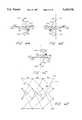
- FIGS. 4A-4Care 4-PSK signal constellations which illustrate the method used to determine trellis path probabilities according to Euclidean distances along a trellis diagram represented in FIG. 4D.
- FIG. 5is a trellis set partitioning tree for a 4-PSK signal constellation.
- FIG. 6is a schematic representation of a trellis coding tree which graphically depicts the signal constellation space for a conventionally encoded Square 16 QAM signal constellation at each level of trellis coding.
- FIG. 7is a schematic representation of a trellis coding tree which graphically depicts the signal constellation space for a 16 Star QAM signal constellation at each level of trellis coding in accordance with the method of the present invention.
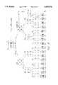
- FIG. 8is an output table for a rate 3/4, 16-state trellis encoder.
- FIG. 9is a next-state table for a rate 3/4, 16-state trellis encoder.
- FIG. 10illustrates the Gray coding assignments for a 16 Star QAM signal constellation.
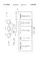
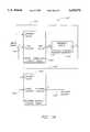
- FIGS. 11A and 11Bare schematic block diagrams which depict the transmitter and receiver, respectively, of a trellis coding modem constructed in accordance with the teachings of the present invention.
- FIG. 12is a schematic representation of the main elements of the forward channel signal stream transmitted from the transmitter of FIG. 11A to the receiver of FIG. 11B.
- FIG. 13is a schematic representation of the reverse channel frame format for the communication system of FIGS. 11A and 11B.
- FIG. 14is a schematic block diagram which shows the main structural and functional elements of a cyclic trellis encoder constructed in accordance with the teachings of the present invention.
- FIG. 15illustrates the 16 Star QAM constellation assignments for the busy/idle and decode status symbols transmitted over the forward channel.
- FIGS. 1A and 1Bgraphically depict signal constellations for a Square 16 QAM scheme and a 16 Star QAM scheme, respectively.
- the signal constellations depicted in FIGS. 1A and 1Bare represented in polar coordinate form wherein each point of the signal constellations represents the determinate phase and the amplitude of an information symbol.
- a point labeled "Q" in FIG. 1Bcorresponds to a signal having an amplitude defined as 1 and a phase of 45°
- a point labeled "P" in FIG. 1Bcorresponds to a signal having an amplitude defined as 2 which has a phase of 90°.
- the inner ring of signal pointsare amplitude value 1 points and the outer ring of signal points are amplitude value 2 points.
- Signal constellationsare a convenient way to graphically depict the binary data encoded by means of various phase and amplitude modulation schemes.
- FIGS. 1A and 1Bthere is a 4-bit binary word ("symbol") associated with each point on the 16-point signal constellations.
- a detectoris configured to assign a specified data word for a detected signal having a given amplitude and phase.
- the detectorwhen a detector (or decoder) detects a signal which has an amplitude closest to 1, and which has a phase closest to 45°, the detector will assign the data word 0011 (decimal 3) to that signal.
- FIGS. 1A and 1Bare merely exemplary. Other assignments are possible, as will be apparent from the discussion below.
- one or more error encoding techniquesare used in order to provide for accurate transmission and detection of data, especially when very high level modulation schemes are employed.
- both Reed-Solomon and trellis encoding techniquesare employed in the transmission of data.
- the combination of these two error coding techniques in the system of the present inventionis advantageous since the trellis decoder produces burst errors (i.e., errors which are typically bunched together in a sequence), while Reed-Solomon encoding is particularly useful for detecting and correcting burst errors.
- the concept of using multiple forward, error-correcting codes, such as trellis coded modulation together with Reed-Solomon encoding,is called concatenated coding.
- Reed-Solomon encodingis a block coding technique which is well known in the art. Briefly, block coding involves appending a series of parity bits onto a block of data. The parity bits contain parity information used for the detection and correction of errors in the data block. Depending upon the number of data bits in the data block, and the number of parity bits appended to each data block, a certain number of errors can be detected and/or corrected in that block at the receiver end. As is well known in the art, Reed-Solomon encoding provides a tradeoff between the number of errors that can be detected and the number of errors that can be corrected.
- n-k errors within the blockcan be detected while a maximum of (n-k)/2 errors can be corrected.
- the decodercannot both detect and correct the maximum numbers set forth above; the more errors which can be corrected, the fewer errors which can be detected by the receiver, and vice versa.
- seven symbol errorsmay be detected, and of those seven, three are correctable by means of the Reed-Solomon encoding. If in a given block of code more errors are detected than can be corrected, then the receiving element of the communication system requests a retransmission of that data block through an automatic repeat request scheme.
- Trellis codingis an error coding technique which is also well known in the art.
- Trellis codesare convolutional codes that are designed and optimized according to a specific modulation scheme.
- a convolutional encoderencodes information symbols based upon the present input symbol and the state of the encoder. The present state of the encoder is determined by the symbols which previously entered the encoder. That is, the encoded symbol is a function of the present input symbol and also symbols that entered the encoder before the present input symbol.
- a convolutional encoderhas memory.
- Convolutional codesare typically implemented by shift registers and summers.
- the next state and the output of the encoderare functions of the present state of the register or look-up table (i.e., the value of the bits presently stored within the register or look-up table memory), and the input to the register or look-up table.
- FIG. 2A and the accompanying table 230 shown in FIG. 2Billustrate an exemplary embodiment of a convolutional encoder 200 implemented by means of shift registers, and the corresponding state table.
- the encoder 200is simply shown here in order to illustrate the operation and implementation of a convolutional encoder, and is not to be construed as an implementation of the trellis encoder used in accordance with the present invention.
- the encoder 200includes shift register memory units 205, 210, 215, as well as summers 220, 225. A one-bit input is encoded into a two-bit output to provide rate 1/2 encoding.
- the encoder 200can be considered to have four possible present states and four possible next states, each two-bit values.
- the encoder 200to be in the present state 10 (i.e., the first two registers 205, 210 contain bits 1, 0, respectively).
- An input of 1will move the encoder 200 to a next state of 11 (i.e., the first two registers 205, 210 contain bits 1, 1, respectively) and generate an output of 01 (decimal 1).
- This processis repeated as each successive bit enters the encoder 200 so that a state diagram can be constructed which shows the possible state transitions of the encoder 200 with the accompanying input and output values which correspond to those transitions.
- FIG. 3is a state transition diagram which indicates the possible state transitions of the encoder 200 of FIG. 2, along with the input and output values corresponding to the possible transitions. Because the state transition diagram resembles a trellis in form, such diagrams are often called trellis diagrams, hence the name "trellis coding.” Each dot on the trellis diagram of FIG. 3 represents a state of the encoder 200. Dots in the same horizontal row correspond to the same state at different times. Dots in the same vertical column represent different states at the same time (i.e., within the duration of the same symbol). Branches between the dots represent possible state transition paths.
- the number pair along each of the branches depicted in FIG. 3indicate the [input, output] values which correspond to a given branch.
- the first numberrepresents the input which causes the transition, while the second number represents the output value resultant upon this transition.
- the possible state transitions for the encoder 200are the same for each successive symbol.
- the same patternrepeats over and over again for each symbol duration.
- the encoder 200begins in the state 0 (binary 00), represented by a dot 300 in FIG. 3.
- state 0binary 00
- the encoder 200goes from state 0 to state 2 (binary 10), represented by a dot 320, via a path 310.
- the encoder 200outputs a value 3 (binary 11). If the value of the next bit applied to the input is 0, then the encoder 200 transitions from state 2 to state 1, represented by a dot 340, via a path 330, while the output of the encoder 200 assumes a value of 2.
- the encoder 200moves from the state 1 to the state 0, represented by a dot 360, via a path 350.
- the encoder 200Upon entering the state 0, the encoder 200 outputs a value 3.
- input bits 1-0-0are encoded by the encoder 200 into output bits 11-10-11, or 3-2-3 in decimal.
- the encoder 200has transitioned from the state 0 to the state 2, to the state 1, and back to the state 0.
- convolutional encodingprovides for a reduced number of detected errors at the receiver.
- a three-bit data stream 1-0-0is properly encoded as 11-10-11 by the encoder 200 as described above.
- the receiverdetects the transmitted signal erroneously as 11-11-11.
- the decoderperforms a maximum likelihood decision based upon the possible state transition paths which the encoder 200 might have taken. Since the encoder is typically set to state 0 at initialization, the decoder assumes that the detected sequence of data bits began in state 0.
- the decoderthen examines all of the paths which began at state 0 and terminate at a state three symbols later as depicted in FIG. 3 for the purpose of illustration. For instance, for an ending point at the state 0, at the point 360, there are two possible paths which the encoder may have taken: the path 310, 330, 350, or the path 370, 380, 390. Of course, all the other paths of three symbol duration are also examined to determine the likelihood that the detected bit sequence followed these possible paths, but for the sake of simplicity of illustration, only the paths from state 0 to state 0 are considered here.
- the decoderdetermines the probability that the detected data sequence was produced by the first path (e.g., the path 310, 330, 350), the probability that the detected data sequence was generated by the second path (e.g., the path 370, 380, 390), and so on until a probability has been calculated for each possible path.
- the path having the highest probabilityis then selected as the actual path according to either hard or soft decision methods described in greater detail below.
- trellis decoding techniquescalculate path probabilities based upon either Hamming or Euclidean distances between the detected signal and the signals generated by the possible trellis paths.
- Euclidean distancesare used as the measure of path probability, as discussed in greater detail below.
- Hamming distanceis also provided,
- Hamming distanceis defined as the number of bits by which two binary sequences differ. For example, the hamming distance between the binary words 110 and 101 is two, while the hamming distance between the binary words 111 and 011 is one, etc. Based upon a Hamming distance evaluation of the possible paths, the probability that a given path has generated a detected data sequence can be determined as follows. Assuming, as stated above, that the detected data sequence is 11-11-11 (with a proper data sequence of 11-10-11), and the possible paths are the paths 310, 330, 350 and 370, 380, 390, the Hamming distance between the detected signal 11-11-11 and the path 310, 330, 350 is 1.
- the binary sequence generated by the path 310, 330, 350is 11-10-11.
- This sequencediffers from the detected sequence 11-11-11 by a Hamming distance of 1.
- the Hamming distance between the detected signal 11-11-11 and the signal generated by the path 370, 380, 390is 6 since the path 370, 380, 390 results in an output binary sequence of 00-00-00.
- Euclidean distanceis the length of a straight line between points on a signal constellation.
- probability measures based upon Euclidean distancesexhibit better accuracy than probability measures based upon Hamming distance. This is because probability measurements based upon Euclidean distance take into account the received signal phase and amplitude information which is discarded when using Hamming distance as a probability metric.
- FIGS. 4A-4Dillustrate a simple 4-PSK modulation signal constellation having four defined points 400, 410, 420, 430 equidistant from the origin and corresponding to output values 00, 01, 10, and 11, respectively.
- phase and amplitude valueswhich are represented by the vectors r1-r3 in FIGS. 4A-4C.
- the vectors r1-r3would simply be approximated as the data points 00, 10, and 00, respectively, so that valuable phase and amplitude information is lost about the actually detected signal sequence.
- the phase and amplitude of the received signalare factored into the determination of the path probability.
- the probability that the detected signal has been generated by the trellis path represented by the dashed line 450is a decreasing function of the sum of the squares of the Euclidean distances d01, d02, and d03, (depicted in FIGS. 4A-4C), while the probability that the detected signal has been generated by the trellis path represented by the dashed/dotted line 470 is a function of the sum of the squares of the Euclidean distances d31, d22, and d33.
- the greater the sum of the squares of the Euclidean distances along a given paththe less likely that path is to be the one which generated the detected signal sequence. In this manner, a more accurate estimation of the transmitted data sequence can be obtained.
- the selection of a given pathmay be made in accordance with block or symbol-by-symbol decision methods.
- a predetermined number of received signals forming a sete.g., 1,000 symbols
- the decoderthen starts with the first signal and constructs a trellis with associated metrics and path histories for the whole set of 1,000 symbols.
- the trellis transition path that is most probableis then selected as the path which generated the detected symbols.
- the data input which would have generated this pathis then determined as the decoded data sequence. Absent any uncorrected errors, this data sequence should correspond to the data sequence fed into the encoder on the transmitter side of the communication system.
- the processis then repeated with the next block of symbols, and so on.
- a predetermined number of received signalsare fed into the decoder. For example, assume 25 signals are fed into the decoder. Once the 25th symbol is entered, the trellis decoder determines what path was most probable. The input symbol which would have generated the first branch of the most probable path is then selected as the output of the decoder. The next (e.g., the 26th) received signal is then fed into the decoder and another determination is made of the most probable path for the last 25 symbols (i.e., excluding the first symbol). The input symbol which would have generated the first branch of the most probable path (i.e., the path for the most recently detected 25 symbols) is then selected as the next output of the decoder. This procedure is carried on symbol-by-symbol in real time so that only one symbol at a time is decoded for output as opposed to an entire block of data at a time.
- a 4-PSK signal constellationTake as a simple example a 4-PSK signal constellation as shown in FIG. 5.
- the possible outputs of the trellis encoder on the transmitter sideare represented as four points which are phase shifted from one another by phase differences of 90°.
- the possible output values, as represented in the signal constellation, as well as the states of the trellis decoderare both considered.
- the trellis diagram of FIG. 3which may, for example, describe state transitions for the 4-PSK signal constellation of FIG.
- FIG. 6graphically represents a trellis coding tree for set partitioning a more complicated Square 16 QAM signal constellation by the Ungerboeck method, which is well known in the art.
- a complex signal constellationis broken up into subsets. It is a requirement of Ungerboeck's set partitioning method that the minimum Euclidean distances measured between any of the points on the subset constellations exceed the minimum Euclidean distance between points on the constellation from which the subsets are derived.
- the minimum Euclidean distance between any two points on the original constellation at the top of the trellis coding treeis less than the minimum Euclidean distance between any points of the constellation shown in subsets B 0 or B 1 .
- the minimum Euclidean distances between any two points on the constellation subsets C 0 and C 2is greater than the minimum Euclidean distance between any two points in the subset B 0 , and so on.
- an increased minimum Euclidean distance between any two points in a signal constellationinsures that the probability of mistaking similar encoder output sequences is minimized.
- the error performance of the coded schemeis a function of the minimum Euclidean distance between any two given paths. To reduce the probability of error, the minimum Euclidean distance must be increased. Therefore, the mapping by set partitioning technique provides for optimum error performance.
- the 16 Star QAM signal constellationdoes not allow for division into subsets such that the minimum Euclidean distance between points increases significantly for each level of partitioning.
- FIG. 7illustrates the difficulty of set partitioning the 16 Star QAM signal constellation. For the first level of set partitioning there is no difficulty; the constellation divides symmetrically, and the minimum Euclidean distance between the point on the first subset is considerably greater than the minimum Euclidean distance between the points on the original constellation. However, at the second level of set partitioning, the minimum Euclidean distances are substantially the same as at the first level of set partitioning. Due to this characteristic of the 16 Star QAM signal constellation, it has been thought that it is not possible to effectively trellis code a 16 Star QAM signal using conventional Ungerboeck coding techniques.
- the present inventionincludes a specially designed trellis encoder/decoder within a transmit/receive communications system.
- the encoder/decoderis constructed to encode according to an inventive method called cyclic trellis coding which has been found to work advantageously for signal constellations such as 16 Star QAM or any arbitrary signal constellation. Cyclic trellis coding is described in detail below.
- Cyclic trellis codinginvolves a method of error encoding which may be adapted to the 16 Star QAM signal constellation, although it has been found that cyclic trellis coding can be applied to modulation schemes with any signal constellation that can be partitioned into two symmetric subsets. Moreover, it has been verified that error performance of a system using cyclic trellis coding, together with a 16 level modulation scheme, is as good or better than systems employing the previously used Ungerboeck codes for trellis encoders having up to 16 states.
- the signal constellationis first partitioned into two sets. This is the same as dividing the possible outputs into two sets of output values.
- the possible states of the encoderare also divided into two sets.
- the output and state partitioningis most readily represented in table form. Because a trellis code is entirely determined by four factors (i.e., the input, the present state, the next state, and the output) a trellis code can be represented by two tables as depicted in FIGS. 8 and 9.
- the table shown in FIG. 8presents the output values as a function of the input and the present state values, while the table shown in FIG. 9 presents the next state values as a function of the input and present state values.
- a rate 3/4 cyclic trellis encoderfor encoding a 16 Star QAM signal partitions the output values into even and odd sets, as represented in the table of FIG. 8.
- a rate 3/4 trellis encoderreceives 3 input lines (corresponding to 8 possible input values) and generates outputs on four lines (corresponding to 16 possible output values).
- a 16-state encoderis sufficient, so that there are 16 present state values and 16 next state values.
- each of the even present-state valuesresults in an even output value upon the application of an input value.
- each of the odd present-state valuesresults in an odd output value upon the application of an input value. For example, if the trellis encoder is presently in state 5 (binary 0101) and an input of 4 (binary 0100) is applied, the output value produced by the encoder is 9 (binary 1001).
- the output valuesare assigned to the 16 Star QAM constellation points according to well known Gray coding techniques.
- FIG. 10shows the Gray coding output assignments for 16 Star QAM constellation.
- the table of FIG. 9represents the next state of a rate 3/4 cyclic trellis encoder as a function of the input and present state values.
- the next state valueis cyclicly partitioned into multiple sets. That is, the first eight next state values (0-7) are assigned, in order, to the first present state value, while the last eight next state values (8-15) are assigned, in order, to the second present state value.
- the first eight next state valuesare then assigned again to the third present state value, but not in order from 0 to 7. Rather, the order is 7, 0, 1, 2, 3, 4, 5, 6.
- the third next state rowis like the first next state row, but cyclicly shifted to the right.
- Every next state rowtakes the last value from the row immediately preceding the previous next state row and places this value in the first position while shifting the other values by one position. This method is repeated until an entire next state table is defined.
- the method described above with reference to a rate 3/4, 16-state trellis encodercan be employed in accordance with other encoder forms as well, such as rate 2/3 trellis encoders, etc.
- the preferred embodiment of the present inventionis the rate 3/4 16-state trellis encoder defined by the tables in FIGS. 8 and 9.
- an encoder defined by the tables in FIGS. 8 and 9may be implemented as a look-up table, or an input/output state machine circuit.
- the system and method of the present inventionprovides trellis coding for 16 Star QAM format signals together with Reed-Solomon block coding to provide a low error communication link.
- the datais further encoded by means of cyclic trellis coding along with well known interleaving operations.
- the transmitterthen inserts synchronization frames and pilot words for purposes of synchronization and channel fading compensation at the receiver.
- the datais then 16 Star QAM mapped, filtered, and transmitted. In order to recover the transmitted data on the receiver side, filtering and synchronized sampling are performed. Deinterleaving, cyclic trellis decoding, and Reed-Solomon decoding are then performed to recover the original data.
- FIGS. 11A and 11Bare block diagrams depicting a specific implementation of one embodiment of a mobile cellular wireless communication system constructed in accordance with the teachings of the present invention.
- the wireless communication system 1100includes a transmitting side or circuit 1105 (FIG. 11A) and a receiving side or circuit 1108 (FIG. 11B).
- the transmitting side 1105 of the wireless communication systemcomprises a Reed-Solomon encoder 1110 which provides an input connection to an outer interleaver 1115.
- the outer interleaver 1115connects to a cyclic trellis coded modulator encoder 1120.
- the structure and operation of the cyclic trellis encoder 1120is described in greater detail below with reference to FIG. 14.
- the output of the trellis coded modulator encoder 1120serves as input to an inner interleaver 1122.
- the inner interleaver 1122connects to a frame synchronization inserter 1125 which connects to a pilot word inserter 1128.
- the output of the pilot word inserter 1128is provided as an input to a 16 Star QAM mapper 1130 which assigns a four-bit binary sequence to a point on the signal constellation by transforming the input symbol into a signal having an assigned phase and amplitude.
- the output of the 16 Star QAM mapper 1130is fed into a Nyquist pulse shaping filter 1133 which in turn connects to an RF transmitter 1135 having a transmitting antenna 1136.
- a modulated carrier signalis transmitted over a communications medium to the receiving side 1108 of the wireless communication system 1100.
- the communications mediumincludes the air between the transmitter base station and the mobile unit, as well as any structures or landscape from which the radio frequency signal may be reflected.
- a receiving antenna 1140connects to an RF receiver 1142, which in turn provides input to a complex multiplier 1144.
- the complex multiplier 1144also receives an input from a digital numerically controlled oscillator/automatic frequency controller (DNCO/AFC) 1158.
- the complex multiplier 1144connects to a nyquist pulse shaping filter 1145.
- the output of the nyquist pulse shaping filter 1145serves as input to an equalizing filter 1148.
- the output of the equalizer filter 1148connects to both a symbol timing recovery circuit 1150 and a sampler 1160.
- the symbol timing recovery circuit 1150connects to an equalizer estimator 1152 which in turn connects to the equalizer filter 1148.
- the sampler 1160also receives inputs from the symbol timing recovery circuit 1150 and provides output to a multiplier 1162, a pilot word extraction circuit 1164, and a frame synchronization extraction circuit 1166.
- the multiplier 1162also receives inputs from a channel estimator 1168.
- the channel estimator 1168receives inputs from the pilot word extraction circuit 1164 and provides outputs to both the equalizer estimator 1152 and the digital numerically controlled oscillator/automatic frequency control circuit 1158.
- the pilot word extraction circuit 1164also provides inputs to the equalizer estimator 1152.
- the multiplier 1162, the channel estimator 1168, and the frame synchronization extraction circuit 1166all provide inputs to an inner de-interleaver 1170.
- the inner de-interleaver 1170provides dual inputs to a trellis decoder 1175 which in turn connects to an outer de-interleaver 1180.
- the outer de-interleaver 1180provides inputs to a Reed-Solomon decoder 1185.
- Reed-Solomon encoder 1110During operation of the wireless communication system, data to be transmitted is input into the Reed-Solomon encoder 1110 wherein conventional Reed-Solomon encoding is performed.
- the purpose of the Reed Solomon encoder 1110is to compensate for burst errors made by the trellis encoder 1120. Burst errors are simply errors which occur close together in the transmission sequence.
- the trellis encoderis susceptible to producing burst errors because trellis encoders make decoding decisions over several symbols. Therefore, if the path is incorrect, several symbols along that path may be incorrectly decoded, so that when a trellis encoding error occurs, it is likely to result in a burst of errors.
- the present embodiment of the Reed-Solomon encoderallows for the detection of seven errors and the correction of three of those errors within each length of the block code.
- the suggested Reed-Solomon codeis the well known (63,53) code having a block length of 63 symbols.
- the encoded sequenceconsists of 53 Reed-Solomon symbols of data and 10 parity symbols produced by methods well known in the art.
- Each Reed-Solomon symbolcontains six information bits or two channel symbols.
- the Reed-Solomon encoded dataserves as the input for the outer interleaver 1115.
- the outer interleaver 1115is used to spread burst errors into adjacent code blocks. This helps the Reed-Solomon encoder to correct for burst errors associated with trellis decoding.
- one preferred embodiment of the inventionincludes a Reed-Solomon decoder which can correct up to three errors within a 63 Reed-Solomon symbol block of code. Thus, for example, if one block of 63 symbols has five errors, while the adjacent block has one error, spreading out the errors so that each block has three errors allows the Reed-Solomon decoder to correct both blocks.
- the outer interleaver 1115is a buffer with S columns and D rows where S stands for the span and D stands for the depth of the interleaver 1115.
- the Reed-Solomon encoded symbolsare written into a matrix by rows, (i.e., first row followed by the second row, etc.) and read out by columns (i.e., first column followed by the second column, etc.).
- this datais written into a row of the matrix having S memory locations (where each memory location contains one Reed-Solomon symbol of data).
- These dataare then read out of the outer interleaver 1115 by columns so that the Reed-Solomon encoded symbols which were once adjacent to one another are separated by D symbol spaces and spread across various Reed-Solomon blocks.
- the span of the outer interleaveris the same as the length of the Reed-Solomon block, 63 Reed-Solomon symbols in this case, or equivalently, 126 channel symbols since every Reed-Solomon symbol comprises two channel symbols.
- the depth of the outer interleavershould be chosen to overcome the burst errors out of the trellis decoder. In one actual embodiment, the interleaving depth is 5 channel symbols.
- the Reed-Solomon encoded and interleaved symbolsenter the cyclic trellis encoder 1120 three bits at a time.
- trellis encodingis used to protect the data against channel impairments.
- the trellis encoder 1120is implemented as a look-up table or as an input/output state machine circuit.
- the trellis encoder 1120also includes a 16 Star QAM mapper (see FIG. 14).
- the 16 Star QAM mappermaps the incoming data sequence into a 16 Star QAM constellation according to Gray coding, a technique which is well known in the art.
- Gray codinginvolves assigning the bit values with the greatest Hamming distance to the signal constellation points which are farthest apart by Euclidean measurements, while those symbols which are closer by Hamming measurements are assigned points in the signal constellation which are closer according to Euclidean measurements.
- 00 and 11would be assigned diametrically opposed points in a 4-PSK constellation, while 00 and 01 would be 90° from one another.
- a specific embodiment of a rate 3/4 cyclic trellis encoderwill be described in greater detail below with reference to FIG. 14.
- the rate of the convolutional encoderis 3/4 in a preferred embodiment. That is, for every three bits input into the encoder 1120, four bits are output, so that there is one parity bit for every three data bits.
- a 3/4 encoding ratein conjunction with a 16-level modulation scheme, provides a bandwidth efficiency of 3 bits per second per hertz. That is, if approximately 30 KHz of bandwidth is used, corresponding to 30 thousand symbols per second, then one symbol is transmitted per second for every one Hz of bandwidth. But each symbol contains four bits in 16 QAM format, of which three are data bits, so that a net transmitting efficiency of approximately 3 bits per second per hertz is achieved.
- the Trellis code used to encode the incoming data symbolsis designed for good error performance over the Rayleigh fading channel.
- the trellis codeis a cyclic trellis code with 16 states, as described in the section above entitled Cyclic Trellis Coding.
- the Trellis encoded symbolsare then block interleaved in the inner interleaver 1122 in much the same manner as described above with reference to the outer interleaver 1115.
- the inner interleaver 1122is used to reduce errors associated with trellis coding due to fading.
- the information signalis transmitted to the receiver over a channel that comprises multiple propagation paths or "multipaths" between the transmitter and the receiver. These multipaths are caused by the reflection of the transmitted signal from hills, buildings, airplanes, discontinuities in the atmosphere, and the like. As the result of multipaths, the signal received by the receiver consists of multiple components that vary in both phase and amplitude.
- the duration and rate of fading observed by a receiveris a function of the speed of the mobile receiver. This is because the landscape characteristics change as the mobile unit changes place, so that different reflections are observed.
- the inner interleaver 1122is used to separate several adjacent faded symbols. This method is particularly beneficial in trellis coded systems since the trellis decoder makes decisions based upon path probability over several symbols. When a deep fade occurs, the probability that an entire path length of symbols will be decoded erroneously is much higher. In order to prevent the erroneous detection of an entire path of symbols, interleaving is performed to spread the effects of fading.
- the depth of the inner interleaver 1122is chosen on the order of the anticipated maximum duration of fade.
- interleaving symbols according to this methoda group of symbols which are normally transmitted together over the duration of a single fade are separated so that the effect of the fade is less concentrated and pronounced in one portion of the signal sequence.
- the memory in the channeli.e., the systematic predictable effects such as Rayleigh fading which occur over a continuous duration
- One commonly employed rule of thumb for calculating the depth of the inner interleaver 1122requires that the maximum expected doppler frequency times the symbol duration times the depth of the inner interleaver 1122 is greater than 0.2.
- f d(V*f c )/C
- Vthe velocity of the mobile unit
- f cthe carrier frequency
- Cthe speed of light.
- the minimum speed at which the mobile unit is to operate with reasonable error performanceis assumed to be 8 Km/hr and the symbol duration is approximately 0.04 ms.
- the depth of the inner interleaver 1122must be greater than 810 channel symbols.
- delay constraint factorsare also considered when determining the dimensions of the inner interleaver 1122. Briefly, whenever interleaving is performed, a delay is produced in the transmission of data.
- the depth of the interleavercannot be indefinitely large.
- the depth of the inner interleaveris chosen to be 252 channel symbols to meet delay constraint criteria.
- the span of the inner interleaver 1122is related to the trellis decoder buffer size which is a function of the constraint length of the code.
- the interleaving spanis chosen to be 10 symbols.
- the resulting total interleaving delay for both the inner and outer interleavers 1115, 1122is approximately 100 milliseconds.
- FIGS. 12 and 13show the forward channel frame format
- FIG. 13shows the reverse channel frame format.
- the forward channelis defined as the channel used to transmit data from a base station to various mobile units.
- the reverse channelis the channel shared by many mobile units to transmit information to a base station.
- the frame synchronization sequenceoccurs at the beginning of the transmission, and includes a series of synchronization symbols.
- synchronizationmay be obtained by means of a sliding correlator circuit.
- one sub frame, together with 13 symbols of an additional sub-frame of synchronization data 1200is followed by a 19-symbol partial sub-frame of data 1205 and 88 full sub-frames of data 1210.
- Each data sub-frame 1210includes 32 symbols beginning with a differential pilot signal pair 1215. Every other sub-frame (i.e., every odd sub-frame) includes three busy/idle, decode status symbols 1220. After the initial pilot signal pair 1215 and the busy/idle, decode status symbols 1220, channel data follows.
- the differential pilot signal pair 1215allows for channel fading compensation and rapid synchronization of the data signal, while the busy/idle decode, status symbols 1220 provide information concerning the status of the reverse channel.
- the pilot signalshave a constant difference.
- the receiver side 1108is equipped with a differential detector which is set to detect the known difference between the pilot signal pair. Since the symbols are adjacent, these symbols undergo substantially the same distortions through the communication medium so that, although both pilot symbols may be distorted, the difference between the pilot symbols remains constant. Thus, this difference can be detected at the receiving end with little difficulty.
- the pilot signalscome at known periods (e.g., every 32 symbols in one embodiment), the detection of the pilot signal difference can be used as a means of synchronizing the timing rate of the data stream.
- the busy/idle symbolsare transmitted across the forward channel by the base station to indicate whether the reverse channel is busy.
- the decode status symbolis transmitted across the forward channel by the base station to indicate whether the last Reed-Solomon block received from the mobile unit was successfully decoded.
- FIG. 15illustrates the points on the 16 Star QAM signal constellation to which the busy/idle and decode status symbols 1120 are assigned.
- the busy/idle symbol(of the busy/idle/decode status symbols 1220 depicted in FIG. 12) is assigned to the signal represented by either the point 1510 or the point 1511 of the signal constellation depicted in FIG. 15. If the busy/idle symbol is assigned to the point 1510, this indicates that the reverse channel is busy; while if the busy/idle symbol is assigned to the point 1511, this indicates that the reverse channel is idle. It should be understood that in one preferred embodiment, two adjacent busy/idle symbols are transmitted having the same value to protect against channel errors. Since the busy/idle symbols are transmitted periodically, the receiver can locate the busy/idle symbols in the received signal sequence.
- the receiver at the mobile unitadds the two adjacently received busy/idle symbols (that is, adds the vectors corresponding to the received busy/idle symbols by means of well known vector addition methods).
- the x-componentalso called the in-phase component, which is the component along line 1530
- the mobile unitdecides that the reverse channel is busy. If the in-phase component of the sum of the received busy/idle vectors is negative (i.e., to the left of the line 1540 in FIG. 15) then the mobile unite decides that the reverse channel is idle.
- the decode status symbol of the forward channel transmission sequenceis assigned to either the point 1520 or the point 1521 on the signal constellation depicted in FIG. 15. If the decode status symbol is assigned to the point 1520, this indicates that the base station has failed to decode the information within the last Reed-Solomon block correctly. If the decode status symbol is assigned to the point 1521, this indicates that the base station has successfully decoded the information within the last Reed-Solomon block.
- the receiver at the mobile unitadds the vectors corresponding to two successively received decode status symbols.
- the y-componentalso called the quadrature component, which is the component along the line 1540
- the mobile unitdecides that the base station has successfully decoded the last Reed-Solomon block. If the quadrature component of the sum of the received decode status vectors is negative (i.e., below the line 1530 in FIG. 15) then the mobile unit determines that the base station has failed to correctly decode the information in the last Reed-Solomon block.
- a 38-symbol dotting sequence 1300is followed by a 22-symbol SYNC word 1310.
- the SYNC word 1310is followed by a series of Reed-Solomon encoded data blocks 1320 which each contain 128 symbols, as shown in the enlarged depiction of the first Reed-Solomon block 1320.
- Each block 1320comprises four 32-symbol segments which each begin with a differential pilot word.
- the differential pilot wordcomprises a pilot symbol 1325 and a frame SYNC symbol 1326.
- a continuity indicator symbol 1330is included at the beginning of every 32-bit segment.
- the 16 Star QAM mappermay be implemented as a signal mapping look-up table which assigns each of the 16 possible output values to a point on the 16 Star QAM signal constellation in accordance with the Gray coding scheme shown in FIG. 10. That is, the output symbol applied to the input of the 16 Star QAM mapper look-up table 1130 is used to determine the amplitude and phase of the encoded symbol. In this way the phase and amplitude coordinates corresponding to each channel symbol are assigned by the 16 Star QAM mapping look-up table 1130.
- the signalis filtered by the Nyquist pulse shaping filter 1133, which is a baseband filter.
- the filteringensures that the data transmission is limited to a 30 KHz bandwidth with no intersymbol interference.
- the pulse shapingis advantageously performed by a square root raised cosine pulse filter, as is commonly used in the art.
- the pulse filterhas a roll-off factor of 0.35. That is, if substantially all the transmission power is to be restricted to a 30 KHz bandwidth, the available transmission bandwidth is 30 KHz/(1+0.35), as will be understood in the art.
- the symbolsare then modulated and amplified in the RF transmitter 1135, and sent to the antenna 1136 for transmission over the communication medium to the receiver side 1108.
- the antenna 1140receives the radio signal sent by the transmitter side 1105 and forwards the received signal to the RF receiver 1142.
- the RF receiver 1142converts the RF signal to baseband frequency.
- the basband signalenters the complex multiplier 1144 where the signal is multiplied by a sinusoidal waveform generated by the oscillator/controller 1158.
- the signal from the oscillator/controller 1158is used to correct the phase shift introduced into the transmitted data signal over the communication medium.
- the waveform generated by the oscillator/controller 1158is the inverse of the average phase shift introduced in the carrier over the channel. The average phase shift is determined within the channel estimator 1168, as discussed further below.
- the complex multiplier 1144combines the incoming signal having a phase shifted carrier frequency with the inverse phase shift signal generated by the oscillator/controller 1158 to output a signal having the original carrier frequency. Once the baseband data signal and the generated sinusoidal waveform have been multiplied to correct for phase shifting errors, the phase compensated signal enters the Nyquist pulse shaping filter 1145.
- the pulse shaping filter 1145which is a baseband filter, removes high frequency noise and adjacent channel interference introduced over the communication medium.
- the filter 1145is also a square root raised cosine filter which, in one embodiment has a roll-off factor of 0.35.
- the filter 1145combines with the filter 1133 to form a first power (i.e., a half power combined with a half power) raised cosine filter.
- the filtered signalenters the equalizer filter 1148.
- the equalizer filter 1148is a standard adaptive linear equalizer which uses channel state and symbol timing feedback information for adaptation purposes. That is, the equalizer filter 1148 removes delay spread from multiple reflections of the same signal received by the receiver. Well known methods such as feed-back decision directed equalization, maximum likelihood equalization, etc. may be used in accordance with the teachings of the present invention. More specifically, the equalizer filter 1148 receives inputs from the equalizer estimator 1152. The equalizer estimator 1152 outputs information relating to the timing of the incoming data stream, which the equalizer estimator receives from the symbol timing recovery circuit 1150. The equalizer estimator 1152 also outputs information to the equalizer filter 1148 relating to the distortions observed over the communication medium. This information is received by the equalizer estimator 1152 as feedback from the pilot word extraction circuit 1164, as will be discussed in greater detail below. Finally, the equalizer estimator 1152 outputs information relating to the channel state to the equalizer filter 1148.
- the equalizer estimator 1152receives channel state information as feedback from the channel estimator 1168. Using the data input from the equalizer estimator 1152, the equalizer filter 1148 sets filtering parameters in order to compensate for distortion introduced to the signal during transmission over the communication medium.
- the equalized signalis output to both the symbol timing recovery circuit 1150 and the sampler 1160.
- the symbol timing recovery circuituses the filtered and equalized signal to extract signal timing from the incomming data signal. This signal timing is then used as input to the sampler circuit 1160 to extract data caried on the signal.
- the sampler 1160digitally samples the incoming signal at a frequency determined by the symbol timing recovery circuit 1150. This sampling rate is sufficient to satisfy Nyquist requirements (e.g., 4 samples are taken per channel symbol in one embodiment). This sampling rate is appropriate to recover the channel symbol with minimum inter-symbol interference.
- the sampled signalserves as inputs to both the pilot word extraction circuit 1164 and the frame synchronization extraction circuit 1166.
- Frame synchronization and pilot word extractionare performed by sliding correlators, a technique which is well known in the art.
- the sliding correlatorhas a memory which stores a reference frame synchronization pattern which matches the transmitted frame sync pattern.
- the reference pattern within the frame synchronization extraction circuit 1166is adjusted (or slid) so that it substantially has the same timing as the incoming synchronization pattern, a high correlation is observed between the incoming signal and the reference pattern. The maximum correlation between the reference pattern and the incoming signal is used to determine the frame synchronization.
- the sliding correlatorhas a memory which stores a reference differential signal which matches the difference between the pilot signals (see FIG. 12).
- the pilot signal extraction circuit 1164includes a differentiator which is able to detect the differences between pairs of symbols. As discussed above with reference to FIG. 12, the pilot signal pairs are chosen to have a constant difference between them. Therefore, since the pilot channel symbols are adjacent to one another during transmission and undergo substantially the same distortion during transmission, the difference between the pilot signal pair remains substantially unaffected during transmission. This determined difference between the incoming pairs of data symbols is compared to and correlated with the reference differential signal by adjusting (sliding) the reference signal along the incoming data stream. Once a high correlation is observed between the reference signal and the incoming data stream, this is an indication that the pilot signal pair has been detected. The pilot word extraction circuit 1164 then extracts the symbols identified as the pilot symbols.
- Information extracted from the pilot signalsis also fed as an input into the channel estimator 1168.
- the channel estimator 1168uses these symbols to interpolate the phase and amplitude distortions which the signal has experienced during transmission through the communication medium. Since the receiver has information relating to the exact expected phase and amplitude of the pilot symbol, and since the receiver has information relating to the phase and amplitude of the actually received signal, an estimation of the phase and amplitude distortions introduced over the communication channel can be made. The complex conjugate of this signal can then be used to multiply the incoming signal to compensate for distortions introduced over the communication medium.
- the channel estimator 1168outputs the phase distortion information to the digital numerically controlled oscillator/controller 1158.
- the oscillator/controller 1158uses these inputs to control the oscillation frequency by methods well understood in the art.
- the channel estimator 1168also outputs a signal which is the complex conjugate of the estimated channel phase (i.e., conjugate of the phase distortion introduced by the communication medium). This complex conjugate signal is multiplied by the received signal in the multiplier circuit 1162. Multiplying the received signal by the conjugate of the channel phase compensates for the phase distortions introduced by the channel phase, as described above.
- Information relating to the amplitude distortions introduced over the communication mediumis passed from the channel estimator 1168 to the trellis decoder 1175 via the inner deinterleaver 1170.
- the inner deinterleaver 1170deinterleaves the phase compensated in-phase and quadrature components of the baseband signal together with the corresponding channel state information provided by the channel estimator 1168.
- the trellis decoder 1175performs maximum likelihood decoding of the sequence through soft decision Viterbi decoding, as described above under the heading Maximum Likelihood Decoding.
- the structure and operation of the decoder 1175is determined from the look-up tables represented in FIGS. 8 and 9.
- the channel state amplitude distortion informationis used to construct the optimum Gaussian decoding metric.
- the Gaussian decoding metricdiffers from the Euclidean coding metric in that the Gaussian decoding metric takes into account the phase shift and amplitude distortion introduced over the communication medium.
- the only distortion factor which remains when calculating probability distances according to Gaussian Metricis the distortion introduced by the additive white Gaussian noise (AWGN), so that a truer probability distribution of the path of the detected signal may be determined.
- AWGNadditive white Gaussian noise
- the trellis decoded symbolsare then passed through the outer deinterleaver 1180 in order to restore their original order.
- the deinterleaved symbolsare then passed on to the Reed-Solomon decoder 1185 which, by methods known in the art, decodes the symbols output from the trellis decoder 1175 to reconstruct the original input data.
- the post trellis decoding information provided by the trellis decoder 1175can also be used by the Reed-Solomon decoder 1185 to perform error and erasure decoding in order to improve performance. Basically, this involves having the trellis decoder 1175 output a likelihood value associated with each symbol to the Reed-Solomon decoder 1185.
- the likelihood valueis a measure of the probability that each decoded symbol is correct.
- FIG. 14is a schematic block diagram which shows the main structural elements of the cyclic trellis encoder 1120 constructed in accordance with the teachings of the present invention.
- the encoder 1120includes a state transition look-up table 1400, which may, for example, be fabricated from a ROM IC chip, or other means.
- a next state output of the state transition look-up table 1400connects to a memory element 1410 via a line 1405.
- the memory element 1410may, in one embodiment, be implemented as a series of D flip-flops.
- the output of the memory element 1410connects to a present state input of the state transition look-up table 1400 via a line 1415 and to a present state input of an output look-up table 1420 via a line 1425.
- the output look-up table 1420outputs an encoded symbol via a line 1435.
- the state transition look-up table 1400 and the output look-up table 1420receive three-bit input symbols via lines 1440, 1445, respectively
- the three-bit input symbolenters the state transition look-up table 1400.
- the present state of the encoderwhich is supplied by the memory element 1410, is applied to the present state input of the state transition look-up table 1400.
- the state transition table 1400Given the present state and the three-bit input signal, the state transition table 1400 outputs a next state value over the line 1405.
- the state transition look-up table 1400is implemented so that the next state value generated by the state transition look-up table 1400 is determined in accordance with the next state table of FIG. 9.
- the next state valueenters the memory element 1410 where the next state value is stored for one input cycle. That is, upon application of the next three-bit input signal, the next state value which was applied to the input of the memory element 1410 is passed to the output of the memory element 1410. Thus, the output of the memory element 1410 corresponds to the present state of the trellis encoder 1120.
- the present state value at the output of the memory element 1410is applied to the inputs of both the state transition look-up table 1400 and the encoder output look-up table 1420.
- the output look-up table 1420receives the present state input via the line 1425 and the input symbol via the line 1445, and generates an encoded four-bit output symbol.
- the output table 1420is implemented so that the output value generated by the output look-up table 1420 is determined in accordance with the output table of FIG. 8. This output value is an encoded output symbol which serves as the output of the encoder 1120.
Landscapes
- Engineering & Computer Science (AREA)
- Computer Networks & Wireless Communication (AREA)
- Signal Processing (AREA)
- Error Detection And Correction (AREA)
- Digital Transmission Methods That Use Modulated Carrier Waves (AREA)
Abstract
Description
Claims (9)
Priority Applications (7)
| Application Number | Priority Date | Filing Date | Title |
|---|---|---|---|
| US08/344,156US5659578A (en) | 1994-11-23 | 1994-11-23 | High rate Reed-Solomon concatenated trellis coded 16 star QAM system for transmission of data over cellular mobile radio |
| CA002203903ACA2203903C (en) | 1994-11-23 | 1995-11-22 | High rate reed-solomon concatenated trellis coded 16 star qam system for transmission of data over cellular mobile radio |
| MX9703830AMX9703830A (en) | 1994-11-23 | 1995-11-22 | High rate reed-solomon concatenated trellis coded 16 star qam system for transmission of data over cellular mobile radio. |
| BR9509749ABR9509749A (en) | 1994-11-23 | 1995-11-22 | 16-star high-rate reed-solomon concatenation lattice qam system for data transmission via cellular mobile radio |
| PCT/US1995/015368WO1996016496A2 (en) | 1994-11-23 | 1995-11-22 | Trellis coded 16 star qam with reed-solomon coding |
| AU43699/96AAU4369996A (en) | 1994-11-23 | 1995-11-22 | High rate reed-solomon concatenated trellis coded 16 star qam system for transmission of data over cellular mobile radio |
| US08/852,151US5838728A (en) | 1994-11-23 | 1997-05-06 | High rate reed-solomon concatenated trellis coded 16 star QAM system for transmission of data over cellular mobile radio |
Applications Claiming Priority (1)
| Application Number | Priority Date | Filing Date | Title |
|---|---|---|---|
| US08/344,156US5659578A (en) | 1994-11-23 | 1994-11-23 | High rate Reed-Solomon concatenated trellis coded 16 star QAM system for transmission of data over cellular mobile radio |
Related Child Applications (1)
| Application Number | Title | Priority Date | Filing Date |
|---|---|---|---|
| US08/852,151ContinuationUS5838728A (en) | 1994-11-23 | 1997-05-06 | High rate reed-solomon concatenated trellis coded 16 star QAM system for transmission of data over cellular mobile radio |
Publications (1)
| Publication Number | Publication Date |
|---|---|
| US5659578Atrue US5659578A (en) | 1997-08-19 |
Family
ID=23349293
Family Applications (2)
| Application Number | Title | Priority Date | Filing Date |
|---|---|---|---|
| US08/344,156Expired - LifetimeUS5659578A (en) | 1994-11-23 | 1994-11-23 | High rate Reed-Solomon concatenated trellis coded 16 star QAM system for transmission of data over cellular mobile radio |
| US08/852,151Expired - LifetimeUS5838728A (en) | 1994-11-23 | 1997-05-06 | High rate reed-solomon concatenated trellis coded 16 star QAM system for transmission of data over cellular mobile radio |
Family Applications After (1)
| Application Number | Title | Priority Date | Filing Date |
|---|---|---|---|
| US08/852,151Expired - LifetimeUS5838728A (en) | 1994-11-23 | 1997-05-06 | High rate reed-solomon concatenated trellis coded 16 star QAM system for transmission of data over cellular mobile radio |
Country Status (6)
| Country | Link |
|---|---|
| US (2) | US5659578A (en) |
| AU (1) | AU4369996A (en) |
| BR (1) | BR9509749A (en) |
| CA (1) | CA2203903C (en) |
| MX (1) | MX9703830A (en) |
| WO (1) | WO1996016496A2 (en) |
Cited By (46)
| Publication number | Priority date | Publication date | Assignee | Title |
|---|---|---|---|---|
| US5796788A (en)* | 1996-04-19 | 1998-08-18 | Ericsson Inc. | Method and apparatus for interference decorrelation in time and space |
| US5838728A (en)* | 1994-11-23 | 1998-11-17 | At&T Wireless Services, Inc. | High rate reed-solomon concatenated trellis coded 16 star QAM system for transmission of data over cellular mobile radio |
| WO1999004516A1 (en)* | 1997-07-21 | 1999-01-28 | Globespan Semiconductor Inc. | Frameless reed-solomon coding system and method |
| US5875215A (en)* | 1995-08-25 | 1999-02-23 | Nec Corporation | Carrier synchronizing unit |
| US5920597A (en)* | 1996-09-16 | 1999-07-06 | Ericsson Inc. | Decoding technique for tail biting codes |
| US5931965A (en)* | 1994-11-23 | 1999-08-03 | At&T Wireless Services, Inc. | Cyclic trellis coded modulation |
| US5938787A (en)* | 1997-03-27 | 1999-08-17 | Ericsson Inc. | Communications systems and methods employing code rate partitioning with nonorthogonal modulation |
| US5946357A (en)* | 1997-01-17 | 1999-08-31 | Telefonaktiebolaget L M Ericsson | Apparatus, and associated method, for transmitting and receiving a multi-stage, encoded and interleaved digital communication signal |
| US5995548A (en)* | 1996-11-15 | 1999-11-30 | 3Com Corporation | Signaling method using multiple modulus shell mapping |
| US6031474A (en)* | 1998-03-10 | 2000-02-29 | Kay; Stanley E. | Half rate coded modulation schemes for Rayleigh fading channels |
| US6034996A (en)* | 1997-06-19 | 2000-03-07 | Globespan, Inc. | System and method for concatenating reed-solomon and trellis codes |
| US6058499A (en)* | 1996-12-20 | 2000-05-02 | Samsung Electronics, Co., Ltd. | Error correcting method and device |
| US6084915A (en)* | 1997-03-03 | 2000-07-04 | 3Com Corporation | Signaling method having mixed-base shell map indices |
| US6084883A (en)* | 1997-07-07 | 2000-07-04 | 3Com Corporation | Efficient data transmission over digital telephone networks using multiple modulus conversion |
| US6091784A (en)* | 1996-09-21 | 2000-07-18 | Daewoo Telecom Ltd. | Method and apparatus for constant envelope quadrature amplitude modulation |
| US6115427A (en)* | 1996-04-26 | 2000-09-05 | At&T Corp. | Method and apparatus for data transmission using multiple transmit antennas |
| US6259748B1 (en)* | 1996-12-31 | 2001-07-10 | Nokia Mobile Phones Limited | Signal offset elimination |
| US6301683B1 (en)* | 1997-06-09 | 2001-10-09 | Vocal Technologies, Ltd. | Trellis encoding technique for PCM modems |
| US20010031017A1 (en)* | 1999-12-15 | 2001-10-18 | Paradyne Corporation | Discrete multitone interleaver |
| US6460156B1 (en)* | 1997-07-18 | 2002-10-01 | Nokia Mobile Phones Ltd. | Data transmission method and system |
| US6542553B1 (en)* | 1996-12-23 | 2003-04-01 | Canon Kabushiki Kaisha | Device and method for transmitting digital data, device and method for receiving digital data and communication devices using them |
| US20030067991A1 (en)* | 2001-09-07 | 2003-04-10 | Communications Research Lab., Ind. Admin, Inst. | Multi-mode block-coded modulation/demodulation method |
| US6581179B1 (en)* | 1996-06-25 | 2003-06-17 | Ericsson Inc. | Methods for generating side information in the presence of time-selective fading |
| US6661856B1 (en) | 1997-11-11 | 2003-12-09 | At&T | Decoding for generalized orthogonal design for space-time codes for wireless communication |
| US6889356B1 (en)* | 1994-11-23 | 2005-05-03 | Cingular Wireless Ii, Llc | Cyclic trellis coded modulation |
| US20050160342A1 (en)* | 2003-12-09 | 2005-07-21 | Stmicroelectronics N.V. | Method and device of de-interleaving successive sequences of interleaved data samples |
| US20050157811A1 (en)* | 2001-12-03 | 2005-07-21 | Bjerke Bjorn A. | Iterative detection and decoding for a MIMO-OFDM system |
| US20050180332A1 (en)* | 2004-02-13 | 2005-08-18 | Broadcom Corporation | Low latency interleaving and deinterleaving |
| US20050195911A1 (en)* | 1999-10-13 | 2005-09-08 | Cellaxon Co. | Communication system |
| EP1108318A4 (en)* | 1998-08-28 | 2005-12-21 | Intersil Inc | A TRANSMISSION SYSTEM AND METHOD THEREFOR, FOR DIGITAL INTERCONNECTION WITH CONDITIONED ENGINES |
| US7054377B1 (en) | 1999-12-15 | 2006-05-30 | Paradyne Corporation | Space diversity trellis interleaver system and method |
| US7088781B2 (en) | 1999-12-15 | 2006-08-08 | Paradyne Corporation | Tone ordered discrete multitone interleaver |
| US20060176977A1 (en)* | 2005-01-14 | 2006-08-10 | Hamid Jafarkhani | Method and apparatus for use of space time trellis codes based on channel phase feedback |
| US20070198888A1 (en)* | 2006-02-23 | 2007-08-23 | Genesis Microchip Inc. | Hard-decision iteration decoding based on an error-correcting code with a low undecectable error probability |
| US20070206695A1 (en)* | 2005-01-12 | 2007-09-06 | Huanchun Ye | Selecting MCS in a MIMO system |
| US20080016431A1 (en)* | 2006-07-12 | 2008-01-17 | Peter Lablans | Error correction by symbol reconstruction in binary and multi-valued cyclic codes |
| US20080037612A1 (en)* | 2006-08-08 | 2008-02-14 | Bogdan Tudosoiu | Minimizing estimation time for rake fingers with help of a speed sensor |
| US20090092058A1 (en)* | 2006-03-07 | 2009-04-09 | The Governors Of The University Of Alberta | Non-Data-Aided Channel Estimators for Multipath and Multiple Antenna Wireless Systems |
| US20110214038A1 (en)* | 2007-07-11 | 2011-09-01 | Ternarylogic Llc | Methods and Systems for Rapid Error Correction of Reed-Solomon Codes |
| US8645803B2 (en) | 2010-05-10 | 2014-02-04 | Ternarylogic Llc | Methods and systems for rapid error correction by forward and reverse determination of coding states |
| US20140105202A1 (en)* | 2004-02-13 | 2014-04-17 | Broadcom Corporation | Encoding system and method for a transmitter in wireless communications |
| US20150188666A1 (en)* | 2013-12-17 | 2015-07-02 | Samsung Electronics Co., Ltd. | Computing system with polar processing mechanism and method of operation thereof |
| CN106797359A (en)* | 2014-10-09 | 2017-05-31 | 高通股份有限公司 | A kind of new modulation scheme for SC FDMA:Tone phase-shift keying (PSK) |
| US10476713B1 (en)* | 2013-04-12 | 2019-11-12 | Sun Patent Trust | Transmission method |
| US20230085866A1 (en)* | 2022-02-14 | 2023-03-23 | David E. Newman | Multiplexed Amplitude-Phase Modulation for 5G/6G Noise Mitigation |
| US20240333558A1 (en)* | 2022-02-14 | 2024-10-03 | David E. Newman | Selecting a Modulation Scheme Responsive to Fault Types in 5G/6G |
Families Citing this family (52)
| Publication number | Priority date | Publication date | Assignee | Title |
|---|---|---|---|---|
| DE69737554D1 (en)* | 1996-08-05 | 2007-05-16 | Matsushita Electric Industrial Co Ltd | DATA TRANSMITTER, RECEIVER, PROCESSOR, DEVICE AND SYSTEM FOR MANAGING EQUIPMENT, DATA ENTRY AND RECEIVING SYSTEM AND TRANSMISSION MEDIUM |
| US6151296A (en)* | 1997-06-19 | 2000-11-21 | Qualcomm Incorporated | Bit interleaving for orthogonal frequency division multiplexing in the transmission of digital signals |
| US6185258B1 (en) | 1997-09-16 | 2001-02-06 | At&T Wireless Services Inc. | Transmitter diversity technique for wireless communications |
| US6157679A (en)* | 1997-10-17 | 2000-12-05 | Motorola, Inc. | Method of adding encryption/encoding element to the modulation/demodulation process |
| EP1808969B1 (en) | 1997-10-31 | 2014-01-01 | AT & T Mobility II, LLC | Maximum likehood detection of concatenated space-time codes for wireless applications with transmitter diversity |
| JP3166705B2 (en)* | 1998-04-16 | 2001-05-14 | 松下電器産業株式会社 | Wireless device and transmission method |
| US6269131B1 (en)* | 1998-05-28 | 2001-07-31 | Glenayre Electronics, Inc. | Physical channel estimator |
| KR100377939B1 (en)* | 1998-09-01 | 2003-06-12 | 삼성전자주식회사 | Frame Composition Device and Method for Subframe Transmission in Mobile Communication System |
| US6608868B1 (en)* | 1999-01-19 | 2003-08-19 | Matsushita Electric Industrial Co., Ltd. | Apparatus and method for digital wireless communications |
| US7545890B1 (en)* | 1999-01-29 | 2009-06-09 | Texas Instruments Incorporated | Method for upstream CATV coded modulation |
| US6421400B1 (en)* | 1999-02-04 | 2002-07-16 | Lsi Logic Corporation | System and method using polar coordinate representation for quantization and distance metric determination in an M-PSK demodulator |
| US6356528B1 (en) | 1999-04-15 | 2002-03-12 | Qualcomm Incorporated | Interleaver and deinterleaver for use in a diversity transmission communication system |
| US6466569B1 (en)* | 1999-09-29 | 2002-10-15 | Trw Inc. | Uplink transmission and reception techniques for a processing satelliteation satellite |
| WO2001030003A1 (en)* | 1999-10-22 | 2001-04-26 | Nextnet Wireless Inc. | Fixed ofdm wireless man utilizing cpe having internal antenna |
| US6580705B1 (en)* | 1999-10-28 | 2003-06-17 | Lucent Technologies Inc. | Signal combining scheme for wireless transmission systems having multiple modulation schemes |
| US6634007B1 (en) | 1999-11-08 | 2003-10-14 | Codevector Technology | Algebraic soft decoding of reed-solomon codes |
| CA2393857A1 (en)* | 1999-12-24 | 2001-07-05 | Ensemble Communications, Inc. | Method and apparatus for concatenated channel coding |
| US6769089B1 (en)* | 1999-12-24 | 2004-07-27 | Ensemble Communicatioins, Inc. | Method and apparatus for concatenated channel coding in a data transmission system |
| US6944235B2 (en)* | 2000-07-12 | 2005-09-13 | Texas Instruments Incorporated | System and method of data communication using trellis coded modulation or turbo trellis coded modulation in combination with constellation shaping with or without precoding when using concatenated coding schemes or when working in a non-error free operation point |
| US6731878B1 (en) | 2000-08-17 | 2004-05-04 | At&T Corp | Free space optical communication link with diversity |
| US6804223B2 (en) | 2000-11-30 | 2004-10-12 | Ipr Licensing, Inc. | Reverse link pilot integrated with block codes |
| US6731700B1 (en)* | 2001-01-04 | 2004-05-04 | Comsys Communication & Signal Processing Ltd. | Soft decision output generator |
| US6807238B1 (en)* | 2001-02-01 | 2004-10-19 | Lsi Logic Corporation | Method and apparatus for decoding M-PSK turbo code using new approximation technique |
| US7020070B2 (en)* | 2001-04-10 | 2006-03-28 | Telefonaktiebolaget L M Ericsson (Publ) | Selectively controlled modulation distortion of an IQ-baseband signal |
| CN1443416A (en)* | 2001-05-17 | 2003-09-17 | 连宇通信有限公司 | A Method of Applying Quadrature Amplitude Modulation to Wireless Mobile Communication System |
| US7385949B1 (en) | 2001-06-05 | 2008-06-10 | Broadcom Corporation | System and method for de-interleaving data in a wireless receiver |
| CN1221113C (en)* | 2001-08-24 | 2005-09-28 | 连宇通信有限公司 | Method and device of chennel decoding based on reliability enhanced deleting convolution code and QAM modulated code |
| US7379509B2 (en)* | 2002-08-19 | 2008-05-27 | Lawrence Livermore National Security, Llc | Digital intermediate frequency QAM modulator using parallel processing |
| US7239672B2 (en)* | 2002-09-05 | 2007-07-03 | Silicon Integrated Systems Corp. | Channel estimator for WLAN |
| US7039004B2 (en)* | 2002-10-01 | 2006-05-02 | Atheros Communications, Inc. | Decision feedback channel estimation and pilot tracking for OFDM systems |
| US7277493B2 (en)* | 2003-01-28 | 2007-10-02 | Agere Systems Inc. | Equalization in orthogonal frequency domain multiplexing |
| KR20050008431A (en)* | 2003-07-15 | 2005-01-21 | 삼성전자주식회사 | Digital broadcasting transmission/reception capable of improving a receiving performance and a method signal processing thereof |
| KR101018381B1 (en)* | 2003-07-15 | 2011-03-02 | 삼성전자주식회사 | Digital broadcasting transmission / reception system with improved reception performance and signal processing method |
| JP4408446B2 (en)* | 2004-03-30 | 2010-02-03 | モデサト・コミュニケーションズ・オー・ユー | Method for transmitting and receiving QAM signals with low signal-to-noise ratio |
| KR20070011481A (en)* | 2004-04-13 | 2007-01-24 | 알자 코포레이션 | Apparatus and method for transdermal delivery of multiple vaccines |
| KR100849344B1 (en)* | 2005-03-07 | 2008-07-29 | 삼성전자주식회사 | Reed-Solomon Code and Decoding Method in Mobile Communication System and Its Apparatus |
| US8290031B1 (en)* | 2006-08-14 | 2012-10-16 | The Board Of Trustees Of The Leland Stanford Junior University | Arrangements and methods for providing compensation for non-idealities of components in communications systems |
| CN101141801A (en)* | 2006-09-06 | 2008-03-12 | 华为技术有限公司 | Channel resource block mapping method and device |
| US7978773B2 (en)* | 2006-12-29 | 2011-07-12 | Agere Systems Inc. | Multi-channel receiver with improved AGC |
| US7809343B2 (en)* | 2007-04-25 | 2010-10-05 | Agere Systems Inc. | Multi-channel receiver with improved AGC |
| US7769357B2 (en)* | 2007-04-25 | 2010-08-03 | Agere Systems Inc. | Multi-channel receiver with improved AGC |
| CN100558096C (en)* | 2007-07-25 | 2009-11-04 | 北京天碁科技有限公司 | A kind of quadrature amplitude modulation demodulation method and device that is applied to communication system |
| US8437431B1 (en)* | 2007-09-20 | 2013-05-07 | Gregory Hubert Piesinger | Sequential decoder fast incorrect path elimination method and apparatus for pseudo-orthogonal coding |
| US8193871B1 (en)* | 2007-10-12 | 2012-06-05 | Quintic Holdings | FM pulse shaping |
| US8782489B2 (en) | 2010-02-18 | 2014-07-15 | Hughes Network Systems, Llc | Method and system for providing Low Density Parity Check (LDPC) encoding and decoding |
| US8674758B2 (en)* | 2011-12-15 | 2014-03-18 | Hughes Network Systems, Llc | Method and apparatus for improved high order modulation |
| US8972834B2 (en) | 2012-08-28 | 2015-03-03 | Hughes Network Systems, Llc | System and method for communicating with low density parity check codes |
| US9294131B2 (en) | 2013-02-10 | 2016-03-22 | Hughes Network Systems, Llc | Apparatus and method for improved modulation and coding schemes for broadband satellite communications systems |
| US9246634B2 (en) | 2013-02-10 | 2016-01-26 | Hughes Network Systems, Llc | Apparatus and method for improved modulation and coding schemes for broadband satellite communications systems |
| US8887024B2 (en) | 2013-02-10 | 2014-11-11 | Hughes Network Systems, Llc | Apparatus and method for improved modulation and coding schemes for broadband satellite communications systems |
| EP2974037B1 (en) | 2013-03-15 | 2018-10-03 | Hughes Network Systems, LLC | Low density parity check (ldpc) encoding and decoding for small terminal applications |
| BR112017010692B1 (en) | 2014-12-04 | 2022-03-03 | Eddy Current Limited Partnership | Activation coupling between elements |
Citations (52)
| Publication number | Priority date | Publication date | Assignee | Title |
|---|---|---|---|---|
| US3988677A (en)* | 1975-06-23 | 1976-10-26 | Nasa | Space communication system for compressed data with a concatenated Reed-Solomon-Viterbi coding channel |
| US4503545A (en)* | 1980-02-19 | 1985-03-05 | Paradyne Corporation | System for evaluating transmission line impairments |
| US4571549A (en)* | 1983-01-07 | 1986-02-18 | Societe Anonyme De Telecommunications | 16-QAM Modulator with PLL amplification devices |
| US4627072A (en)* | 1983-06-10 | 1986-12-02 | Nec Corporation | Equalizer modifying a phase of a gain control signal to carry out equalization |
| US4788696A (en)* | 1986-06-18 | 1988-11-29 | Fujitsu Limited | Decision timing control circuit |
| US4817116A (en)* | 1984-04-17 | 1989-03-28 | Nec Corporation | Digital radio communication system utilizing quadrature modulated carrier waves |
| US4825457A (en)* | 1988-04-25 | 1989-04-25 | Lebowitz Mayer M | Cellular network data transmission system |
| US4835483A (en)* | 1986-09-30 | 1989-05-30 | Nec Corporation | QAM demodulator with rapid resynchronization function |
| US4882737A (en)* | 1987-07-31 | 1989-11-21 | Bbc Brown Boveri Ag | Signal transmission method |
| US4888778A (en)* | 1986-10-27 | 1989-12-19 | Thomson-Csf | Algebraic coder-decoder for Reed Solomon and BCH block codes, applicable to telecommunications |
| US4891823A (en)* | 1988-10-26 | 1990-01-02 | General Datacomm Inc. | Channel encoder for generating rotationally invariant trellis codes |
| US4899367A (en)* | 1988-02-02 | 1990-02-06 | Communications Research Laboratory Ministry Of Posts And Telecommunications | Multi-level quadrature amplitude modulator system with fading compensation means |
| US4905255A (en)* | 1989-01-03 | 1990-02-27 | American Telephone And Telegraph Company | Decision directed gain control |
| US4918437A (en)* | 1988-10-13 | 1990-04-17 | Motorola, Inc. | High data rate simulcast communication system |
| US4922507A (en)* | 1987-12-01 | 1990-05-01 | California Institute Of Technology | Multiple trellis coded modulation |
| US4939555A (en)* | 1987-05-13 | 1990-07-03 | At&T Bell Laboratories | Trellis coding arrangement |
| US4941154A (en)* | 1989-05-30 | 1990-07-10 | At&T Bell Laboratories | Trellis coding method and arrangement for fractional bit rates |
| US4945549A (en)* | 1986-11-13 | 1990-07-31 | The United States Of America As Represented By The Administrator Of The National Aeronautics And Space Administration | Trellis coded modulation for transmission over fading mobile satellite channel |
| US4965536A (en)* | 1988-05-28 | 1990-10-23 | Nec Corporation | Quadrature amplitude modulation system using digital filters |
| US4968966A (en)* | 1988-10-13 | 1990-11-06 | Motorola, Inc. | High data rate simulcast communication system |
| US4968955A (en)* | 1988-11-25 | 1990-11-06 | Nec Corporation | Carrier phase synchronizing circuit capable of recovering carrier phase synchronization at a short time |
| US4972506A (en)* | 1988-03-15 | 1990-11-20 | Telefonaktiebolaget L M Ericssson | Method of transmitting data information in a mobile, cellular radio communication system |
| US4993046A (en)* | 1988-06-24 | 1991-02-12 | Nippon Telegraph And Telephone Corporation | Coded modulation communication system |
| US5005186A (en)* | 1987-03-20 | 1991-04-02 | Fujitsu Limited | Digital demodulator apparatus |
| US5023889A (en)* | 1988-05-31 | 1991-06-11 | California Institute Of Technology | Trellis coded multilevel DPSK system with doppler correction for mobile satellite channels |
| US5023900A (en)* | 1989-12-07 | 1991-06-11 | Tayloe Daniel R | Cellular radiotelephone diagnostic system |
| US5054110A (en)* | 1989-12-29 | 1991-10-01 | Motorola, Inc. | Multi-site dispatching system cell registration |
| US5057786A (en)* | 1989-06-22 | 1991-10-15 | Sharp Kabushiki Kaisha | Quadrature amplitude modulation wave demodulator provided with band-pass filters for fixed equalizer |
| US5077790A (en)* | 1990-08-03 | 1991-12-31 | Motorola, Inc. | Secure over-the-air registration of cordless telephones |
| US5081649A (en)* | 1989-06-01 | 1992-01-14 | Northern Telecom Limited | Method of quadrature-phase amplitude modulation |
| WO1992003656A1 (en)* | 1990-08-16 | 1992-03-05 | Lundquist, Mona | Fluid-powered turbine with built-in floating elements and current direction intensifiers |
| US5095500A (en)* | 1989-12-07 | 1992-03-10 | Motorola, Inc. | Cellular radiotelephone diagnostic system |
| US5111483A (en)* | 1989-08-07 | 1992-05-05 | Motorola, Inc. | Trellis decoder |
| US5113411A (en)* | 1989-07-31 | 1992-05-12 | Nec Corporation | Modulator and demodulator for data transmission systems |
| US5113401A (en)* | 1989-07-07 | 1992-05-12 | International Business Machines Corporation | Block coding scheme for fractional-bit transmission |
| US5114644A (en)* | 1991-02-13 | 1992-05-19 | Corning Incorporated | Fabrication of cordierite bodies |
| US5115454A (en)* | 1987-05-12 | 1992-05-19 | Kucar Andy D | Method and apparatus for carrier synchronization and data detection |
| US5119375A (en)* | 1985-03-20 | 1992-06-02 | International Mobile Machines Corp. | Subscriber RF telephone system for providing multiple speech and/or data signals simultaneously over either a single or a plurality of RF channels |
| US5119401A (en)* | 1989-11-17 | 1992-06-02 | Nec Corporation | Decision feedback equalizer including forward part whose signal reference point is shiftable depending on channel response |
| US5128967A (en)* | 1989-07-24 | 1992-07-07 | Motorola, Inc. | Symbol state trellis maximum likelihood detection method |
| US5134634A (en)* | 1989-08-31 | 1992-07-28 | Nec Corporation | Multilevel quadrature amplitude demodulator capable of compensating for a quadrature phase deviation of a carrier signal pair |
| US5140615A (en)* | 1990-06-12 | 1992-08-18 | Motorola, Inc. | Maximal ratio diversity combining technique |
| US5168509A (en)* | 1989-04-12 | 1992-12-01 | Kabushiki Kaisha Toshiba | Quadrature amplitude modulation communication system with transparent error correction |
| US5175875A (en)* | 1989-04-02 | 1992-12-29 | Sony Corporation | Radio communication apparatus with programmable signal modulation |
| US5251236A (en)* | 1991-04-05 | 1993-10-05 | At&T Paradyne Corporation | Fractional rate modem with trellis |
| US5258987A (en)* | 1992-04-16 | 1993-11-02 | At&T Bell Laboratories | Multilevel coding using trellis-coded modulation and reed-solomon codes |
| US5263033A (en)* | 1990-06-22 | 1993-11-16 | At&T Bell Laboratories | Joint data and channel estimation using fast blind trellis search |
| US5311582A (en)* | 1991-08-06 | 1994-05-10 | International Teleservice Corporation | Integrated cocot and regulated paystation telephone system |
| US5331553A (en)* | 1992-04-15 | 1994-07-19 | Ugm Medical Systems, Inc. | Three dimensional image reconstruction for a positron emission tomograph |
| EP0623831A1 (en)* | 1993-05-03 | 1994-11-09 | AT&T Corp. | Method and apparatus for fusion splicing optical fibers |
| US5428631A (en)* | 1993-02-01 | 1995-06-27 | Qualcomm Incorporated | Method and apparatus for resolving phase ambiguities in trellis coded modulated data |
| US5475716A (en)* | 1994-01-18 | 1995-12-12 | Gi Corporation | Method for communicating block coded digital data with associated synchronization/control data |
Family Cites Families (9)
| Publication number | Priority date | Publication date | Assignee | Title |
|---|---|---|---|---|
| US4713817A (en)* | 1985-04-25 | 1987-12-15 | Codex Corporation | Multidimensional, convolutionally coded communication systems |
| US5144644A (en)* | 1989-10-13 | 1992-09-01 | Motorola, Inc. | Soft trellis decoding |
| US5134635A (en)* | 1990-07-30 | 1992-07-28 | Motorola, Inc. | Convolutional decoder using soft-decision decoding with channel state information |
| US5233630A (en)* | 1991-05-03 | 1993-08-03 | Qualcomm Incorporated | Method and apparatus for resolving phase ambiguities in trellis coded modulated data |
| US5311553A (en)* | 1992-06-15 | 1994-05-10 | General Electric Company | Trellis coding technique to increase adjacent channel interference protection ratio in land mobile radio systems under peak power constraints |
| US5311552A (en)* | 1992-06-15 | 1994-05-10 | General Electric Company | Trellis coding technique to improve adjacent channel interference protection ratio in land mobile radio systems |
| US5418798A (en)* | 1993-04-09 | 1995-05-23 | At&T Corp. | Multidimensional trellis-coded communication system |
| US5659578A (en)* | 1994-11-23 | 1997-08-19 | At&T Wireless Services, Inc. | High rate Reed-Solomon concatenated trellis coded 16 star QAM system for transmission of data over cellular mobile radio |
| US5675590A (en)* | 1994-11-23 | 1997-10-07 | At&T Wireless Services, Inc. | Cyclic trellis coded modulation |
- 1994
- 1994-11-23USUS08/344,156patent/US5659578A/ennot_activeExpired - Lifetime
- 1995
- 1995-11-22MXMX9703830Apatent/MX9703830A/enunknown
- 1995-11-22AUAU43699/96Apatent/AU4369996A/ennot_activeAbandoned
- 1995-11-22WOPCT/US1995/015368patent/WO1996016496A2/enactiveApplication Filing
- 1995-11-22BRBR9509749Apatent/BR9509749A/ennot_activeIP Right Cessation
- 1995-11-22CACA002203903Apatent/CA2203903C/ennot_activeExpired - Lifetime
- 1997
- 1997-05-06USUS08/852,151patent/US5838728A/ennot_activeExpired - Lifetime
Patent Citations (53)
| Publication number | Priority date | Publication date | Assignee | Title |
|---|---|---|---|---|
| US3988677A (en)* | 1975-06-23 | 1976-10-26 | Nasa | Space communication system for compressed data with a concatenated Reed-Solomon-Viterbi coding channel |
| US4503545A (en)* | 1980-02-19 | 1985-03-05 | Paradyne Corporation | System for evaluating transmission line impairments |
| US4571549A (en)* | 1983-01-07 | 1986-02-18 | Societe Anonyme De Telecommunications | 16-QAM Modulator with PLL amplification devices |
| US4627072A (en)* | 1983-06-10 | 1986-12-02 | Nec Corporation | Equalizer modifying a phase of a gain control signal to carry out equalization |
| US4817116A (en)* | 1984-04-17 | 1989-03-28 | Nec Corporation | Digital radio communication system utilizing quadrature modulated carrier waves |
| US5119375A (en)* | 1985-03-20 | 1992-06-02 | International Mobile Machines Corp. | Subscriber RF telephone system for providing multiple speech and/or data signals simultaneously over either a single or a plurality of RF channels |
| US5121391A (en)* | 1985-03-20 | 1992-06-09 | International Mobile Machines | Subscriber RF telephone system for providing multiple speech and/or data singals simultaneously over either a single or a plurality of RF channels |
| US4788696A (en)* | 1986-06-18 | 1988-11-29 | Fujitsu Limited | Decision timing control circuit |
| US4835483A (en)* | 1986-09-30 | 1989-05-30 | Nec Corporation | QAM demodulator with rapid resynchronization function |
| US4888778A (en)* | 1986-10-27 | 1989-12-19 | Thomson-Csf | Algebraic coder-decoder for Reed Solomon and BCH block codes, applicable to telecommunications |
| US4945549A (en)* | 1986-11-13 | 1990-07-31 | The United States Of America As Represented By The Administrator Of The National Aeronautics And Space Administration | Trellis coded modulation for transmission over fading mobile satellite channel |
| US5005186A (en)* | 1987-03-20 | 1991-04-02 | Fujitsu Limited | Digital demodulator apparatus |
| US5115454A (en)* | 1987-05-12 | 1992-05-19 | Kucar Andy D | Method and apparatus for carrier synchronization and data detection |
| US4939555A (en)* | 1987-05-13 | 1990-07-03 | At&T Bell Laboratories | Trellis coding arrangement |
| US4882737A (en)* | 1987-07-31 | 1989-11-21 | Bbc Brown Boveri Ag | Signal transmission method |
| US4922507A (en)* | 1987-12-01 | 1990-05-01 | California Institute Of Technology | Multiple trellis coded modulation |
| US4899367A (en)* | 1988-02-02 | 1990-02-06 | Communications Research Laboratory Ministry Of Posts And Telecommunications | Multi-level quadrature amplitude modulator system with fading compensation means |
| US4972506A (en)* | 1988-03-15 | 1990-11-20 | Telefonaktiebolaget L M Ericssson | Method of transmitting data information in a mobile, cellular radio communication system |
| US4825457A (en)* | 1988-04-25 | 1989-04-25 | Lebowitz Mayer M | Cellular network data transmission system |
| US4965536A (en)* | 1988-05-28 | 1990-10-23 | Nec Corporation | Quadrature amplitude modulation system using digital filters |
| US5023889A (en)* | 1988-05-31 | 1991-06-11 | California Institute Of Technology | Trellis coded multilevel DPSK system with doppler correction for mobile satellite channels |
| US4993046A (en)* | 1988-06-24 | 1991-02-12 | Nippon Telegraph And Telephone Corporation | Coded modulation communication system |
| US4968966A (en)* | 1988-10-13 | 1990-11-06 | Motorola, Inc. | High data rate simulcast communication system |
| US4918437A (en)* | 1988-10-13 | 1990-04-17 | Motorola, Inc. | High data rate simulcast communication system |
| US4891823A (en)* | 1988-10-26 | 1990-01-02 | General Datacomm Inc. | Channel encoder for generating rotationally invariant trellis codes |
| US4968955A (en)* | 1988-11-25 | 1990-11-06 | Nec Corporation | Carrier phase synchronizing circuit capable of recovering carrier phase synchronization at a short time |
| US4905255A (en)* | 1989-01-03 | 1990-02-27 | American Telephone And Telegraph Company | Decision directed gain control |
| US5175875A (en)* | 1989-04-02 | 1992-12-29 | Sony Corporation | Radio communication apparatus with programmable signal modulation |
| US5168509A (en)* | 1989-04-12 | 1992-12-01 | Kabushiki Kaisha Toshiba | Quadrature amplitude modulation communication system with transparent error correction |
| US4941154A (en)* | 1989-05-30 | 1990-07-10 | At&T Bell Laboratories | Trellis coding method and arrangement for fractional bit rates |
| US5081649A (en)* | 1989-06-01 | 1992-01-14 | Northern Telecom Limited | Method of quadrature-phase amplitude modulation |
| US5057786A (en)* | 1989-06-22 | 1991-10-15 | Sharp Kabushiki Kaisha | Quadrature amplitude modulation wave demodulator provided with band-pass filters for fixed equalizer |
| US5113401A (en)* | 1989-07-07 | 1992-05-12 | International Business Machines Corporation | Block coding scheme for fractional-bit transmission |
| US5128967A (en)* | 1989-07-24 | 1992-07-07 | Motorola, Inc. | Symbol state trellis maximum likelihood detection method |
| US5113411A (en)* | 1989-07-31 | 1992-05-12 | Nec Corporation | Modulator and demodulator for data transmission systems |
| US5111483A (en)* | 1989-08-07 | 1992-05-05 | Motorola, Inc. | Trellis decoder |
| US5134634A (en)* | 1989-08-31 | 1992-07-28 | Nec Corporation | Multilevel quadrature amplitude demodulator capable of compensating for a quadrature phase deviation of a carrier signal pair |
| US5119401A (en)* | 1989-11-17 | 1992-06-02 | Nec Corporation | Decision feedback equalizer including forward part whose signal reference point is shiftable depending on channel response |
| US5023900A (en)* | 1989-12-07 | 1991-06-11 | Tayloe Daniel R | Cellular radiotelephone diagnostic system |
| US5095500A (en)* | 1989-12-07 | 1992-03-10 | Motorola, Inc. | Cellular radiotelephone diagnostic system |
| US5054110A (en)* | 1989-12-29 | 1991-10-01 | Motorola, Inc. | Multi-site dispatching system cell registration |
| US5140615A (en)* | 1990-06-12 | 1992-08-18 | Motorola, Inc. | Maximal ratio diversity combining technique |
| US5263033A (en)* | 1990-06-22 | 1993-11-16 | At&T Bell Laboratories | Joint data and channel estimation using fast blind trellis search |
| US5077790A (en)* | 1990-08-03 | 1991-12-31 | Motorola, Inc. | Secure over-the-air registration of cordless telephones |
| WO1992003656A1 (en)* | 1990-08-16 | 1992-03-05 | Lundquist, Mona | Fluid-powered turbine with built-in floating elements and current direction intensifiers |
| US5114644A (en)* | 1991-02-13 | 1992-05-19 | Corning Incorporated | Fabrication of cordierite bodies |
| US5251236A (en)* | 1991-04-05 | 1993-10-05 | At&T Paradyne Corporation | Fractional rate modem with trellis |
| US5311582A (en)* | 1991-08-06 | 1994-05-10 | International Teleservice Corporation | Integrated cocot and regulated paystation telephone system |
| US5331553A (en)* | 1992-04-15 | 1994-07-19 | Ugm Medical Systems, Inc. | Three dimensional image reconstruction for a positron emission tomograph |
| US5258987A (en)* | 1992-04-16 | 1993-11-02 | At&T Bell Laboratories | Multilevel coding using trellis-coded modulation and reed-solomon codes |
| US5428631A (en)* | 1993-02-01 | 1995-06-27 | Qualcomm Incorporated | Method and apparatus for resolving phase ambiguities in trellis coded modulated data |
| EP0623831A1 (en)* | 1993-05-03 | 1994-11-09 | AT&T Corp. | Method and apparatus for fusion splicing optical fibers |
| US5475716A (en)* | 1994-01-18 | 1995-12-12 | Gi Corporation | Method for communicating block coded digital data with associated synchronization/control data |
Non-Patent Citations (60)
| Title |
|---|
| "Convolutional Encoding; Viterbi and Sequential Decoding", Chapter 12, pp. 353-443. |
| "Modems and Digital Modulation Techniques", Chapter 17, pp. 474-489, Digital Radio and Space Communication. |
| Chow, Y.C., Nix, A.R., and McGeehan, J.P., "Analysis of 16-APSK Modulation in AWGN and Rayleigh Fading Channel", Electronics Letters, Vo. 28, No. 17, pp. 1608-1610, Aug. 12, 1992. |
| Chow, Y.C., Nix, A.R., and McGeehan, J.P., Analysis of 16 APSK Modulation in AWGN and Rayleigh Fading Channel , Electronics Letters, Vo. 28, No. 17, pp. 1608 1610, Aug. 12, 1992.* |
| Convolutional Encoding; Viterbi and Sequential Decoding , Chapter 12, pp. 353 443.* |
| Dimakis, C.E., Prof. Kouris, S.S., Avramis, S.K., "Performance Evaluation of Concatenated Coding Schemes on Multilevel QAM Signalling in Non-Gaussian Products Environment", IEEE Proceedings-1, vol. 140, No. 4, Aug. 1993, pp. 269-276. |
| Dimakis, C.E., Prof. Kouris, S.S., Avramis, S.K., Performance Evaluation of Concatenated Coding Schemes on Multilevel QAM Signalling in Non Gaussian Products Environment , IEEE Proceedings 1, vol. 140, No. 4, Aug. 1993, pp. 269 276.* |
| Dimakis, et al., "Performance evaluation of concatenated coding schemes on multilevel QAM signalling in non-Gaussian products environment", IEE Proceedings-I, vol. 140, No. 4, pp. 269-276, Aug. 1993. |
| Dimakis, et al., Performance evaluation of concatenated coding schemes on multilevel QAM signalling in non Gaussian products environment , IEE Proceedings I, vol. 140, No. 4, pp. 269 276, Aug. 1993.* |
| Divsalar, D. and Simon, M.K., "The Design of Trellis Coded MPSK for Fading Channels: Performance Criteria", pp. 1004-1012, IEEE Transactions Communications, vol. 36, No. 9, Sep. 1988. |
| Divsalar, D. and Simon, M.K., The Design of Trellis Coded MPSK for Fading Channels: Performance Criteria , pp. 1004 1012, IEEE Transactions Communications, vol. 36, No. 9, Sep. 1988.* |
| Eyuboglu, et al., "Advanced Modulation Techniques for V.Fast", ETT, vol. 4, No. 3, May-Jun. 1993. |
| Eyuboglu, et al., Advanced Modulation Techniques for V.Fast , ETT, vol. 4, No. 3, May Jun. 1993.* |
| Eyuboglu, M. Vedat, Forney, G. David, Dong, Ping, Long Guozhu, "Advanced Modulation Techniques for V.Fast", European Transaction on Telecommunications, vol. 4, No. 3, May-Jun. 1993, pp. 243-256. |
| Eyuboglu, M. Vedat, Forney, G. David, Dong, Ping, Long Guozhu, Advanced Modulation Techniques for V.Fast , European Transaction on Telecommunications, vol. 4, No. 3, May Jun. 1993, pp. 243 256.* |
| Haccoun, et al., Digital Communications by Satellite, 7.8 "M-ARY Data Transmission Systems" pp. 569-574. |
| Haccoun, et al., Digital Communications by Satellite, 7.8 "Reception of Binary Data Using Different Signaling Techniques" pp. 550-562. |
| Haccoun, et al., Digital Communications by Satellite, 7.8 M ARY Data Transmission Systems pp. 569 574.* |
| Haccoun, et al., Digital Communications by Satellite, 7.8 Reception of Binary Data Using Different Signaling Techniques pp. 550 562.* |
| Hanzo, et al., "On QAM Speech Transmission Schemes for Microcellular Mobile PCNs", Telecommunication Systems, vol. 4, No. 5, pp. 495-510, Sep.-Oct. 1993. |
| Hanzo, et al., On QAM Speech Transmission Schemes for Microcellular Mobile PCNs , Telecommunication Systems, vol. 4, No. 5, pp. 495 510, Sep. Oct. 1993.* |
| Jain, Yogendra, Convolutional Codes Improve Bit Error Rate in Digital Systems, pp. 129 134, EDN, Aug. 20, 1990.* |
| Jain, Yogendra, Convolutional Codes Improve Bit-Error Rate in Digital Systems, pp. 129-134, EDN, Aug. 20, 1990. |
| Liu, et al., "Error Probability for Digital Transmission Over Nonlinear Channels with Application to TCM", IEEE, pp. 1101-1110, No. 5, Sep. 1990. |
| Liu, et al., Error Probability for Digital Transmission Over Nonlinear Channels with Application to TCM , IEEE, pp. 1101 1110, No. 5, Sep. 1990.* |
| Liu, Yow Jong, Biglieri, Ezio, Error Probability for Digital Transmission Over Nonlinear Channels with Application to TCM , IEEE Transactions on Information Theory, 36 (1990) Sep., No. 5.* |
| Liu, Yow-Jong, Biglieri, Ezio, "Error Probability for Digital Transmission Over Nonlinear Channels with Application to TCM", IEEE Transactions on Information Theory, 36 (1990) Sep., No. 5. |
| Modems and Digital Modulation Techniques , Chapter 17, pp. 474 489, Digital Radio and Space Communication.* |
| Reudink, D.O., "Large-Scale Variations of the Average Signal", pp. 79-307, Microwave Mobile Communications, Jakes, W.C., Mobile Radio Propagation, Chapter 2, IEEE Press, 1974. |
| Reudink, D.O., Large Scale Variations of the Average Signal , pp. 79 307, Microwave Mobile Communications, Jakes, W.C., Mobile Radio Propagation, Chapter 2, IEEE Press, 1974.* |
| Spenler, et al., "Differentially Coherent TC-PSK with Subset Dilation", IEICE Transactions, vol. E74, No. 8, pp. 2220-2229, Aug. 1991. |
| Spenler, et al., Differentially Coherent TC PSK with Subset Dilation , IEICE Transactions, vol. E74, No. 8, pp. 2220 2229, Aug. 1991.* |
| Spenler, Stephen J., Yongacoglu, Abbas, Falconer, David D., "Differentially Coherent TC-PSK with Subset Dilation", IEICE Transactions, vol. E 74, No. 8, Aug. 1991, pp. 2220-2229. |
| Spenler, Stephen J., Yongacoglu, Abbas, Falconer, David D., Differentially Coherent TC PSK with Subset Dilation , IEICE Transactions, vol. E 74, No. 8, Aug. 1991, pp. 2220 2229.* |
| Ungerboeck, G., "Channel Coding with Multilevel/Phase Signals", pp. 55-67, IEEE Communications Magazine, vol.-IT-28, No. 1, Jan. 1982. |
| Ungerboeck, G., Channel Coding with Multilevel/Phase Signals , pp. 55 67, IEEE Communications Magazine, vol. IT 28, No. 1, Jan. 1982.* |
| Ungerboeck, G., Trellis Coded Modulation with Redundant Signal Sets Part 1:Introduction. pp. 5 11, IEEE Communications Magazine, vol. 25, No. 2, Feb. 1987.* |
| Ungerboeck, G., Trellis Coded Modulation with Redundant Signal Sets Part 2: State of the Art, pp. 12 21, IEEE Communications Magazine, vol. 25, No. 2, Feb. 1987.* |
| Ungerboeck, G., Trellis-Coded Modulation with Redundant Signal Sets Part 1:Introduction. pp. 5-11, IEEE Communications Magazine, vol. 25, No. 2, Feb. 1987. |
| Ungerboeck, G., Trellis-Coded Modulation with Redundant Signal Sets Part 2: State of the Art, pp. 12-21, IEEE Communications Magazine, vol. 25, No. 2, Feb. 1987. |
| Ungerboeck, Gottfried, "Channel Coding with Multilevel/Phase Signals", IEEE Transactions on Information Theory, vol. IT-28, No. 1, Jan. 1982, pp. 55-66. |
| Ungerboeck, Gottfried, Channel Coding with Multilevel/Phase Signals , IEEE Transactions on Information Theory, vol. IT 28, No. 1, Jan. 1982, pp. 55 66.* |
| Viterbi, A.J., Wolf, J.K., Zehavi, E., and Padovani, R., "A Pragmatic Approach to Trellis-Coded Modulation", pp. 11-19, IEEE Communications Magazine, Jul. 1989. |
| Viterbi, A.J., Wolf, J.K., Zehavi, E., and Padovani, R., A Pragmatic Approach to Trellis Coded Modulation , pp. 11 19, IEEE Communications Magazine, Jul. 1989.* |
| Vucetic, B. and Du Jun, "Performance Bounds and New 16-QAM Trellis Codes for Fading Channels", pp. 353-363, Coded Modulation and Bandwith-Efficient Transmission, Biglieri, Luise, M. |
| Vucetic, B. and Du Jun, Performance Bounds and New 16 QAM Trellis Codes for Fading Channels , pp. 353 363, Coded Modulation and Bandwith Efficient Transmission, Biglieri, Luise, M.* |
| Webb, "Modulation Methods for PCNs: For optimal efficiency, macrocellular and microcellular personal communications systems may require different modulation schemes", IEEE Communications Magazine, pp. 90-95, Dec. 1992. |
| Webb, et al., "Does 16-QAM Provide an Alternative to a Half-Rate GSM Speech Codec?", IEEE, pp. 511-516, 1991. |
| Webb, et al., Does 16 QAM Provide an Alternative to a Half Rate GSM Speech Codec , IEEE, pp. 511 516, 1991.* |
| Webb, Modulation Methods for PCNs: For optimal efficiency, macrocellular and microcellular personal communications systems may require different modulation schemes , IEEE Communications Magazine, pp. 90 95, Dec. 1992.* |
| Webb, W.T. "Modulation Methods for PCN's", IEEE Communications Magazine, Dec. 1992, pp. 90-95. |
| Webb, W.T. Modulation Methods for PCN s , IEEE Communications Magazine, Dec. 1992, pp. 90 95.* |
| Webb, W.T., Hanzo, L., Steele, R., "Bandwidth Efficient QAM Schemes for Rayleigh Fading Channels, IEE Proceedings-1", vol. 138, No. 3, Jun. 1991, pp. 169-175. |
| Webb, W.T., Hanzo, L., Steele, R., Bandwidth Efficient QAM Schemes for Rayleigh Fading Channels, IEE Proceedings 1 , vol. 138, No. 3, Jun. 1991, pp. 169 175.* |
| Weber, W.J., III, "Differential Encoding for Multiple Amplitude and Phase Shift Keying Systems", pp. 385-391, IEEE Communications Magazine, vol. Com-26, No. 3, Mar. 1978. |
| Weber, W.J., III, Differential Encoding for Multiple Amplitude and Phase Shift Keying Systems , pp. 385 391, IEEE Communications Magazine, vol. Com 26, No. 3, Mar. 1978.* |
| Zein, et al., "Optimum erasure threshold in Reed-Solomon coded differential 16 star-QAM modulation", Electronics Letters, vol. 29, No. 20, pp. 1746-1748, Sep. 30, 1993. |
| Zein, et al., Optimum erasure threshold in Reed Solomon coded differential 16 star QAM modulation , Electronics Letters, vol. 29, No. 20, pp. 1746 1748, Sep. 30, 1993.* |
| Zein, N.F, Clarkson, T.G., "Optimum Erasure Threshold in Reed-Solomon Coded Differential 16-Star-QAM Modulation", Electronics Letters, vol. 29, No. 20, Sep. 30, 1993, pp. 1746-1747. |
| Zein, N.F, Clarkson, T.G., Optimum Erasure Threshold in Reed Solomon Coded Differential 16 Star QAM Modulation , Electronics Letters, vol. 29, No. 20, Sep. 30, 1993, pp. 1746 1747.* |
Cited By (88)
| Publication number | Priority date | Publication date | Assignee | Title |
|---|---|---|---|---|
| US5838728A (en)* | 1994-11-23 | 1998-11-17 | At&T Wireless Services, Inc. | High rate reed-solomon concatenated trellis coded 16 star QAM system for transmission of data over cellular mobile radio |
| US8037396B2 (en)* | 1994-11-23 | 2011-10-11 | At&T Mobility Ii Llc | Cyclic trellis coded modulation |
| US6889356B1 (en)* | 1994-11-23 | 2005-05-03 | Cingular Wireless Ii, Llc | Cyclic trellis coded modulation |
| US5931965A (en)* | 1994-11-23 | 1999-08-03 | At&T Wireless Services, Inc. | Cyclic trellis coded modulation |
| US20050254606A1 (en)* | 1994-11-23 | 2005-11-17 | Alamouti Siavash M | Cyclic trellis coded modulation |
| US5875215A (en)* | 1995-08-25 | 1999-02-23 | Nec Corporation | Carrier synchronizing unit |
| US5796788A (en)* | 1996-04-19 | 1998-08-18 | Ericsson Inc. | Method and apparatus for interference decorrelation in time and space |
| US8386898B2 (en) | 1996-04-26 | 2013-02-26 | At&T Intellectual Property Ii, L.P. | Method and apparatus for data transmission using multiple transmit antennas |
| US9780922B2 (en) | 1996-04-26 | 2017-10-03 | At&T Intellectual Property Ii, L.P. | Method and apparatus for data transmission using multiple transmit antennas |
| US7298794B2 (en) | 1996-04-26 | 2007-11-20 | At&T Corp. | Method and apparatus for data transmission using multiple transmit antennas |
| US8694876B2 (en) | 1996-04-26 | 2014-04-08 | At&T Intellectual Property Ii, L.P. | Method and apparatus for data transmission using multiple transmit antennas |
| US6115427A (en)* | 1996-04-26 | 2000-09-05 | At&T Corp. | Method and apparatus for data transmission using multiple transmit antennas |
| US9083508B2 (en) | 1996-04-26 | 2015-07-14 | At&T Intellectual Property Ii, L.P. | Method and apparatus for data transmission using multiple transmit antennas |
| US6889355B1 (en) | 1996-04-26 | 2005-05-03 | At&T Corp. | Method and apparatus for data transmission using multiple transmit antennas |
| US8352845B2 (en) | 1996-04-26 | 2013-01-08 | At&T Intellectual Property Ii, L.P. | Method and apparatus for data transmission using multiple transmit antennas |
| US6581179B1 (en)* | 1996-06-25 | 2003-06-17 | Ericsson Inc. | Methods for generating side information in the presence of time-selective fading |
| US5920597A (en)* | 1996-09-16 | 1999-07-06 | Ericsson Inc. | Decoding technique for tail biting codes |
| US6091784A (en)* | 1996-09-21 | 2000-07-18 | Daewoo Telecom Ltd. | Method and apparatus for constant envelope quadrature amplitude modulation |
| US5995548A (en)* | 1996-11-15 | 1999-11-30 | 3Com Corporation | Signaling method using multiple modulus shell mapping |
| US6058499A (en)* | 1996-12-20 | 2000-05-02 | Samsung Electronics, Co., Ltd. | Error correcting method and device |
| US6542553B1 (en)* | 1996-12-23 | 2003-04-01 | Canon Kabushiki Kaisha | Device and method for transmitting digital data, device and method for receiving digital data and communication devices using them |
| US6259748B1 (en)* | 1996-12-31 | 2001-07-10 | Nokia Mobile Phones Limited | Signal offset elimination |
| US5946357A (en)* | 1997-01-17 | 1999-08-31 | Telefonaktiebolaget L M Ericsson | Apparatus, and associated method, for transmitting and receiving a multi-stage, encoded and interleaved digital communication signal |
| US6084915A (en)* | 1997-03-03 | 2000-07-04 | 3Com Corporation | Signaling method having mixed-base shell map indices |
| US5938787A (en)* | 1997-03-27 | 1999-08-17 | Ericsson Inc. | Communications systems and methods employing code rate partitioning with nonorthogonal modulation |
| US6848073B2 (en) | 1997-06-09 | 2005-01-25 | Vocal Technologies, Ltd. | Trellis encoding technique for PCM modems |
| US6301683B1 (en)* | 1997-06-09 | 2001-10-09 | Vocal Technologies, Ltd. | Trellis encoding technique for PCM modems |
| US6034996A (en)* | 1997-06-19 | 2000-03-07 | Globespan, Inc. | System and method for concatenating reed-solomon and trellis codes |
| US6084883A (en)* | 1997-07-07 | 2000-07-04 | 3Com Corporation | Efficient data transmission over digital telephone networks using multiple modulus conversion |
| US6460156B1 (en)* | 1997-07-18 | 2002-10-01 | Nokia Mobile Phones Ltd. | Data transmission method and system |
| US6219386B1 (en) | 1997-07-21 | 2001-04-17 | Globespan, Inc. | Frameless reed-solomon coding system and method |
| WO1999004516A1 (en)* | 1997-07-21 | 1999-01-28 | Globespan Semiconductor Inc. | Frameless reed-solomon coding system and method |
| US6661856B1 (en) | 1997-11-11 | 2003-12-09 | At&T | Decoding for generalized orthogonal design for space-time codes for wireless communication |
| US6031474A (en)* | 1998-03-10 | 2000-02-29 | Kay; Stanley E. | Half rate coded modulation schemes for Rayleigh fading channels |
| USRE43963E1 (en) | 1998-08-28 | 2013-02-05 | Intersil Americas Inc. | Constrained-envelope digital-communications transmission system and method therefor |
| EP1108318A4 (en)* | 1998-08-28 | 2005-12-21 | Intersil Inc | A TRANSMISSION SYSTEM AND METHOD THEREFOR, FOR DIGITAL INTERCONNECTION WITH CONDITIONED ENGINES |
| USRE41380E1 (en) | 1998-08-28 | 2010-06-15 | Sicom, Inc. | Constrained-envelope digital-communications transmission system and method therefor |
| US20050195911A1 (en)* | 1999-10-13 | 2005-09-08 | Cellaxon Co. | Communication system |
| US7054377B1 (en) | 1999-12-15 | 2006-05-30 | Paradyne Corporation | Space diversity trellis interleaver system and method |
| US7099401B2 (en) | 1999-12-15 | 2006-08-29 | Paradyne Corporation | Discrete multitone interleaver |
| US7418048B2 (en) | 1999-12-15 | 2008-08-26 | Paradyne Corporation | Tone ordered discrete multitone interleaver |
| US7088781B2 (en) | 1999-12-15 | 2006-08-08 | Paradyne Corporation | Tone ordered discrete multitone interleaver |
| US20010031017A1 (en)* | 1999-12-15 | 2001-10-18 | Paradyne Corporation | Discrete multitone interleaver |
| US7190737B2 (en)* | 2001-09-07 | 2007-03-13 | National Institute Of Information And Communications Technology | Multi-mode block-coded modulation/demodulation method |
| US20030067991A1 (en)* | 2001-09-07 | 2003-04-10 | Communications Research Lab., Ind. Admin, Inst. | Multi-mode block-coded modulation/demodulation method |
| US20050157811A1 (en)* | 2001-12-03 | 2005-07-21 | Bjerke Bjorn A. | Iterative detection and decoding for a MIMO-OFDM system |
| US20080212657A1 (en)* | 2001-12-03 | 2008-09-04 | Qualcomm Incorporated | Iterative detection and decoding for a mimo-ofdm system |
| US20050160342A1 (en)* | 2003-12-09 | 2005-07-21 | Stmicroelectronics N.V. | Method and device of de-interleaving successive sequences of interleaved data samples |
| US7370246B2 (en)* | 2003-12-09 | 2008-05-06 | Stmicroelectronics N.V. | Method and device of de-interleaving successive sequences of interleaved data samples |
| US8996949B2 (en)* | 2004-02-13 | 2015-03-31 | Broadcom Corporation | Encoding system and method for a transmitter in wireless communications |
| US20050180332A1 (en)* | 2004-02-13 | 2005-08-18 | Broadcom Corporation | Low latency interleaving and deinterleaving |
| US20140105202A1 (en)* | 2004-02-13 | 2014-04-17 | Broadcom Corporation | Encoding system and method for a transmitter in wireless communications |
| US20070206695A1 (en)* | 2005-01-12 | 2007-09-06 | Huanchun Ye | Selecting MCS in a MIMO system |
| US7764727B2 (en) | 2005-01-12 | 2010-07-27 | Atheros Communications, Inc. | Selecting MCS in a MIMO system |
| WO2006076697A3 (en)* | 2005-01-12 | 2007-11-22 | Atheros Comm Inc | Selecting mcs in a mimo system |
| US20060176977A1 (en)* | 2005-01-14 | 2006-08-10 | Hamid Jafarkhani | Method and apparatus for use of space time trellis codes based on channel phase feedback |
| CN101427507B (en)* | 2005-01-14 | 2012-01-11 | 加利福尼亚大学董事会 | Method and apparatus for use of space time trellis codes based on channel phase feedback |
| US7599419B2 (en) | 2005-01-14 | 2009-10-06 | The Regents Of The University Of California | Method and apparatus for use of space time trellis codes based on channel phase feedback |
| WO2006076527A3 (en)* | 2005-01-14 | 2007-11-15 | Univ California | Method and apparatus for use of space time trellis codes based on channel phase feedback |
| US7617435B2 (en)* | 2006-02-23 | 2009-11-10 | Yuwei Zhang | Hard-decision iteration decoding based on an error-correcting code with a low undetectable error probability |
| US20070198888A1 (en)* | 2006-02-23 | 2007-08-23 | Genesis Microchip Inc. | Hard-decision iteration decoding based on an error-correcting code with a low undecectable error probability |
| US20090092058A1 (en)* | 2006-03-07 | 2009-04-09 | The Governors Of The University Of Alberta | Non-Data-Aided Channel Estimators for Multipath and Multiple Antenna Wireless Systems |
| US20080016431A1 (en)* | 2006-07-12 | 2008-01-17 | Peter Lablans | Error correction by symbol reconstruction in binary and multi-valued cyclic codes |
| US9203438B2 (en) | 2006-07-12 | 2015-12-01 | Ternarylogic Llc | Error correction by symbol reconstruction in binary and multi-valued cyclic codes |
| US20080037612A1 (en)* | 2006-08-08 | 2008-02-14 | Bogdan Tudosoiu | Minimizing estimation time for rake fingers with help of a speed sensor |
| US7848388B2 (en)* | 2006-08-08 | 2010-12-07 | Sony Ericsson Mobile Communications Ab | Minimizing estimation time for rake fingers with help of a speed sensor |
| US20130145237A1 (en)* | 2007-07-11 | 2013-06-06 | Ternarylogic Llc | Methods and Systems for Rapid Error Location in Reed-Solomon Codes |
| US8201060B2 (en)* | 2007-07-11 | 2012-06-12 | Ternarylocig LLC | Methods and systems for rapid error correction of Reed-Solomon codes |
| US20110214038A1 (en)* | 2007-07-11 | 2011-09-01 | Ternarylogic Llc | Methods and Systems for Rapid Error Correction of Reed-Solomon Codes |
| US8645803B2 (en) | 2010-05-10 | 2014-02-04 | Ternarylogic Llc | Methods and systems for rapid error correction by forward and reverse determination of coding states |
| US10742459B2 (en)* | 2013-04-12 | 2020-08-11 | Sun Patent Trust | Transmission method |
| US10476713B1 (en)* | 2013-04-12 | 2019-11-12 | Sun Patent Trust | Transmission method |
| US20150188666A1 (en)* | 2013-12-17 | 2015-07-02 | Samsung Electronics Co., Ltd. | Computing system with polar processing mechanism and method of operation thereof |
| US9602241B2 (en)* | 2013-12-17 | 2017-03-21 | Samsung Electronics Co., Ltd. | Computing system with polar processing mechanism and method of operation thereof |
| US20170346667A1 (en)* | 2014-10-09 | 2017-11-30 | Qualcomm Incorporated | Tone-phase-shift keying: a new modulation scheme for sc-fdma |
| JP2017531397A (en)* | 2014-10-09 | 2017-10-19 | クゥアルコム・インコーポレイテッドQualcomm Incorporated | Tone phase modulation: a new modulation scheme for SC-FDMA |
| US9762422B2 (en)* | 2014-10-09 | 2017-09-12 | Qualcomm Incorporated | Tone-phase-shift keying: a new modulation scheme for SC-FDMA |
| US10484219B2 (en)* | 2014-10-09 | 2019-11-19 | Qualcomm Incorporated | Tone-phase-shift keying: a new modulation scheme for SC-FDMA |
| CN106797359B (en)* | 2014-10-09 | 2020-06-05 | 高通股份有限公司 | A new modulation scheme for SC-FDMA: tone phase shift keying |
| CN106797359A (en)* | 2014-10-09 | 2017-05-31 | 高通股份有限公司 | A kind of new modulation scheme for SC FDMA:Tone phase-shift keying (PSK) |
| US11736320B2 (en)* | 2022-02-14 | 2023-08-22 | Ultralogic 6G, Llc | Multiplexed amplitude-phase modulation for 5G/6G noise mitigation |
| US20230085866A1 (en)* | 2022-02-14 | 2023-03-23 | David E. Newman | Multiplexed Amplitude-Phase Modulation for 5G/6G Noise Mitigation |
| US20230353428A1 (en)* | 2022-02-14 | 2023-11-02 | David E. Newman | Demodulation Using Two Modulation Schemes in 5G and 6G |
| US11811565B1 (en)* | 2022-02-14 | 2023-11-07 | David E. Newman | Demodulation using two modulation schemes in 5G and 6G |
| US20240031205A1 (en)* | 2022-02-14 | 2024-01-25 | David E. Newman | Modulation and Demodulation for Enhanced Noise Margins in 5G and 6G |
| US12034571B2 (en)* | 2022-02-14 | 2024-07-09 | David E. Newman | Modulation and demodulation for enhanced noise margins in 5G and 6G |
| US20240333558A1 (en)* | 2022-02-14 | 2024-10-03 | David E. Newman | Selecting a Modulation Scheme Responsive to Fault Types in 5G/6G |
| US12250100B2 (en)* | 2022-02-14 | 2025-03-11 | David E. Newman | Selecting a modulation scheme responsive to fault types in 5G/6G |
Also Published As
| Publication number | Publication date |
|---|---|
| US5838728A (en) | 1998-11-17 |
| WO1996016496A2 (en) | 1996-05-30 |
| MX9703830A (en) | 1997-12-31 |
| WO1996016496A3 (en) | 1996-08-08 |
| CA2203903C (en) | 2007-09-25 |
| CA2203903A1 (en) | 1996-05-30 |
| AU4369996A (en) | 1996-06-17 |
| BR9509749A (en) | 1997-12-23 |
Similar Documents
| Publication | Publication Date | Title |
|---|---|---|
| US5659578A (en) | High rate Reed-Solomon concatenated trellis coded 16 star QAM system for transmission of data over cellular mobile radio | |
| US5878085A (en) | Trellis coded modulation communications using pilot bits to resolve phase ambiguities | |
| CN1463525B (en) | Apparatus and method for decision feedback sequence estimation for reduction of error propagation in decision feedback equalizer | |
| US5675590A (en) | Cyclic trellis coded modulation | |
| US6160854A (en) | Concatenated trellis coded modulation and linear block codes | |
| US5511096A (en) | Quadrature amplitude modulated data for standard bandwidth television channel | |
| US4713829A (en) | Coded modulation system with a simplified decoder capable of reducing the effects of channel distortion | |
| CA2266108C (en) | Iterative demapping | |
| US6516037B1 (en) | Multilevel coding with time diversity | |
| EP2184864A2 (en) | Method and apparatus for data transmission using multiple transmit antennas | |
| US20040158798A1 (en) | Error correction circuit and error correction method | |
| WO1996016492A1 (en) | System and method for wireless transmission of digital data using differentially encoded pilot words | |
| US5910967A (en) | Pragmatic encoder and method therefor | |
| US8037396B2 (en) | Cyclic trellis coded modulation | |
| JP3979789B2 (en) | Digital signal receiver | |
| US20050008097A1 (en) | Coded modulation scheme for a wirelesss communication system and methods thereof | |
| JP2000315957A (en) | Decryption device | |
| US6781447B2 (en) | Multi-pass phase tracking loop with rewind of current waveform in digital communication systems | |
| KR101191176B1 (en) | Method for Selection of Symbol Mapping Scheme in BICM System | |
| US20030112899A1 (en) | Decision directed phase locked loops (DD-PLL) with excess processing power in digital communication systems | |
| Kekrt et al. | Low-complexity iterative soft-output demodulation for hierarchical quadrature amplitude modulation | |
| WO2002041550A1 (en) | Non-linear code-division multiple access technology with improved detection algorithms and error correction coding | |
| JP2003110468A (en) | Reception apparatus and method, transmission apparatus and method, communication system, record medium, and program | |
| Soyjaudah et al. | A modified trellis extracted synchronisation technique (TEST) for linear block codes |
Legal Events
| Date | Code | Title | Description |
|---|---|---|---|
| AS | Assignment | Owner name:MCCAW CELLULAR COMMUNICATIONS, INC., WASHINGTON Free format text:ASSIGNMENT OF ASSIGNORS INTEREST;ASSIGNOR:MPR TELTECH LTD.;REEL/FRAME:007241/0281 Effective date:19941118 Owner name:MPR TELTECH LTD., CANADA Free format text:ASSIGNMENT OF ASSIGNORS INTEREST;ASSIGNORS:ALAMOUTI, SIAVASH M.;HAYMOND, WILLIAM D.;WRIGHT, ANDREW S.;REEL/FRAME:007241/0278 Effective date:19941118 | |
| AS | Assignment | Owner name:AT&T WIRELESS SERVICES, INC, WASHINGTON Free format text:ASSIGNMENT OF ASSIGNORS INTEREST;ASSIGNOR:MCCAW CELLULAR COMMUNICATIONS, INC;REEL/FRAME:007725/0802 Effective date:19951108 | |
| STCF | Information on status: patent grant | Free format text:PATENTED CASE | |
| CC | Certificate of correction | ||
| FPAY | Fee payment | Year of fee payment:4 | |
| FPAY | Fee payment | Year of fee payment:8 | |
| AS | Assignment | Owner name:CINGULAR WIRLEESS II, LLC, GEORGIA Free format text:CERTIFICATE OF CONVERSION;ASSIGNOR:CINGULAR WIRELESS II, INC.;REEL/FRAME:017546/0612 Effective date:20041027 Owner name:CINGULAR WIRLEESS II, LLC,GEORGIA Free format text:ASSIGNMENT OF ASSIGNORS INTEREST;ASSIGNOR:CINGULAR WIRELESS II, INC.;REEL/FRAME:017546/0612 Effective date:20041027 Owner name:CINGULAR WIRELESS II, INC.,GEORGIA Free format text:ASSIGNMENT OF ASSIGNORS INTEREST;ASSIGNOR:NEW CINGULAR WIRELESS SERVICES, INC. F/K/A AT&T WIRELESS SERVICES, INC.;REEL/FRAME:017555/0711 Effective date:20041027 Owner name:CINGULAR WIRELESS II, INC., GEORGIA Free format text:ASSIGNMENT OF ASSIGNORS INTEREST;ASSIGNOR:NEW CINGULAR WIRELESS SERVICES, INC. F/K/A AT&T WIRELESS SERVICES, INC.;REEL/FRAME:017555/0711 Effective date:20041027 Owner name:CINGULAR WIRLEESS II, LLC, GEORGIA Free format text:ASSIGNMENT OF ASSIGNORS INTEREST;ASSIGNOR:CINGULAR WIRELESS II, INC.;REEL/FRAME:017546/0612 Effective date:20041027 | |
| AS | Assignment | Owner name:CINGULAR WIRELESS II, LLC,GEORGIA Free format text:CERTIFICATE OF CONVERSION;ASSIGNOR:CINGULAR WIRELESS II, INC.;REEL/FRAME:017696/0375 Effective date:20041027 Owner name:CINGULAR WIRELESS II, LLC, GEORGIA Free format text:CERTIFICATE OF CONVERSION;ASSIGNOR:CINGULAR WIRELESS II, INC.;REEL/FRAME:017696/0375 Effective date:20041027 | |
| AS | Assignment | Owner name:AT&T MOBILITY II, LLC, GEORGIA Free format text:CHANGE OF NAME;ASSIGNOR:CINGULAR WIRELESS II, LLC;REEL/FRAME:020863/0670 Effective date:20070420 | |
| AS | Assignment | Owner name:AT&T MOBILITY II LLC, GEORGIA Free format text:CHANGE OF NAME;ASSIGNOR:AT&T MOBILITY II, LLC;REEL/FRAME:020936/0370 Effective date:20070830 | |
| FPAY | Fee payment | Year of fee payment:12 |